

Page 1
Welch Allyn Connex
Monitor 6000 Series™
®
Vital Signs
Service manual
Software versions 2.0X – 2.4X
Page 2

© 2018 Welch Allyn. All rights are reserved. To support the intended use of the product described in this
publication, the purchaser of the product is permitted to copy this publication, for internal distribution
only, from the media provided by Welch Allyn. No other use, reproduction, or distribution of this
publication, or any part of it, is permitted without written permission from Welch Allyn. Welch Allyn
assumes no responsibility for any injury to anyone, or for any illegal or improper use of the product, that
may result from failure to use this product in accordance with the instructions, cautions, warnings, or
statement of intended use published in this manual.
Welch Allyn, Connex, SureTemp, and SureBP are registered trademarks of Welch Allyn.
Oridion is a registered trademark of Oridion Medical 1987 Ltd. No implied license. Possession or
purchase of this device does not convey any express or implied license to use the device with
unauthorized CO2 sampling products which would, alone, or in combination with this device, fall within
the scope of one or more of the patents relating to this device and/or CO2 sampling products.
RRa is a trademark of; and SET, SpHb, rainbow, and Masimo are registered trademarks of Masimo
Corporation. Possession or purchase of a Masimo-equipped device does not convey any express or
implied license to use the device with unauthorized sensors or cables which would, alone or in
combination with this device, fall within the scope of one or more of the patents relating to this device.
Nellcor is a registered trademark of Covidien, PLC.
Braun and ThermoScan are registered trademarks of Braun GmbH.
Nonin is a registered trademark of Nonin Medical, Inc.
Bluetooth is a registered trademark of Bluetooth SIG.
Welch Allyn has provided Clinical Dynamics of CT, LLC, the calibration tables (CALTables) for use in its
AccuPulse and AccuSim NIBP Simulators. For more information, visit http://www.clinicaldynamics.com/
contact.htm
Software in this product is Copyright 2018 Welch Allyn or its vendors. All rights are reserved. The
software is protected by United States of America copyright laws and international treaty provisions
applicable worldwide. Under such laws, the licensee is entitled to use the copy of the software
incorporated with this instrument as intended in the operation of the product in which it is embedded.
The software may not be copied, decompiled, reverse-engineered, disassembled, or otherwise reduced
to human-perceivable form. This is not a sale of the software or any copy of the software; all right, title,
and ownership of the software remain with Welch Allyn or its vendors.
This product may contain software known as “free” or “open source” software (FOSS). Welch Allyn
uses and supports the use of FOSS. We believe that FOSS makes our products more robust and secure,
and gives us and our customers greater flexibility. To learn more about FOSS that may be used in this
product, please visit our FOSS website at
FOSS source code is available on our FOSS website.
For patent information, please visit www.welchallyn.com/patents.
For information about any Welch Allyn product, contact your local Welch Allyn representative:
www.welchallyn.com/about/company/locations.htm.
DIR 80023124 Ver. A
Revision date: 2018-05
www.welchallyn.com/opensource. Where required, a copy of
Welch Allyn, Inc.
4341 State Street Road
Skaneateles Falls, NY 13153 USA
www.welchallyn.com
Regulatory Affairs Representative
Welch Allyn Limited
Navan Business Park
Dublin Road
Navan, County Meath
Republic of Ireland
Page 3

Contents
Symbols ................................................................................................... 1
Safety ....................................................................................................... 5
Overview .................................................................................................. 9
iii
Warnings and cautions ......................................................................................... 5
General safety considerations .............................................................................. 6
Electrostatic discharge (ESD) ............................................................................... 6
Purpose and scope .............................................................................................. 9
Technical support services ................................................................................. 10
Recommended service intervals ........................................................................ 14
The Welch Allyn Service Tool ............................................................................ 15
Battery performance .......................................................................................... 16
Controls, indicators, and connectors ................................................... 19
Service menu ......................................................................................... 23
Advanced settings and Service tabs .................................................................. 23
General tab ......................................................................................................... 23
Self-tests tab ...................................................................................................... 26
Logs tab ............................................................................................................. 27
Device tab .......................................................................................................... 27
Licensing tab ...................................................................................................... 27
Password tab ..................................................................................................... 28
Power-up sequence ............................................................................... 29
Troubleshooting .................................................................................... 31
Symptoms and solutions ................................................................................... 31
Technical alarm messages ................................................................................. 46
Disassembly and repair ........................................................................ 67
Required tools and equipment ........................................................................... 69
Disassembly overview ....................................................................................... 70
Section A ................................................................................................ 71
Power down the device ..................................................................................... 71
Remove the battery ........................................................................................... 71
Remove the rear housing ................................................................................... 72
Remove the communications door .................................................................... 75
Disassemble the rear housing ........................................................................... 78
Page 4

iv Contents Welch Allyn Connex® Vital Signs Monitor 6000 Series™
Disassemble the main chassis ........................................................................... 86
Disassemble the front housing ........................................................................ 112
Section B .............................................................................................. 127
Power down the device ................................................................................... 127
Remove the battery ......................................................................................... 128
Remove the rear housing ................................................................................. 129
Remove the communications door .................................................................. 132
Disassemble the rear housing ......................................................................... 135
Disassemble the main chassis ......................................................................... 145
Disassemble the front housing ........................................................................ 172
Functional verification and calibration .............................................. 187
Functional verification tests ............................................................................. 187
Basic functional verification checks ................................................................. 190
Electrical safety testing ....................................................................... 207
Ground stud connector .................................................................................... 208
Options, upgrades, and licenses ........................................................ 209
Available options, upgrades, and licenses ....................................................... 210
Install options ................................................................................................... 212
Host firmware requirements ............................................................................ 215
Masimo parameter upgrades ........................................................................... 215
Configure options ............................................................................................. 216
Wireless radio security credentials .................................................................. 216
Certification authority (CA) root certificates ..................................................... 220
Chinese fonts and input method editor (IME) tables ....................................... 221
Field replaceable units ........................................................................ 223
Rear housing .................................................................................................... 224
Bottom housing ............................................................................................... 231
Extended bottom housing ................................................................................ 234
Extended top housing ...................................................................................... 236
Top housing ..................................................................................................... 236
Side panels ....................................................................................................... 238
Front housing and midsection .......................................................................... 239
Miscellaneous parts ......................................................................................... 243
Combined kits .................................................................................................. 244
Options ............................................................................................................ 245
Braun ThermoScan PRO 6000 thermometer and dock ................................... 252
Braun ThermoScan PRO 4000 thermometer and dock ................................... 254
Service parts for Braun ThermoScan PRO thermometers and dock ............... 255
Licenses ........................................................................................................... 256
Partners in Care service and support agreements ........................................... 256
Service and repair training ................................................................................ 258
Service tools .................................................................................................... 259
Appendices .......................................................................................... 261
Decontamination and cleaning requirements for returns ................................. 261
Clean the CO2 input connector ........................................................................ 263
Identifying the monitor and subsystems ......................................................... 263
Page 5

Service manual Contents v
Factory defaults ............................................................................................... 266
Disassembly and repair reference ................................................................... 285
Interconnect diagram ....................................................................................... 294
Service and maintenance toolset ..................................................................... 297
Service record .................................................................................................. 300
Page 6

vi Contents Welch Allyn Connex® Vital Signs Monitor 6000 Series™
Page 7
Symbols
For information on the origin of these symbols, see the Welch Allyn symbols glossary:
www.welchallyn.com/symbolsglossary.
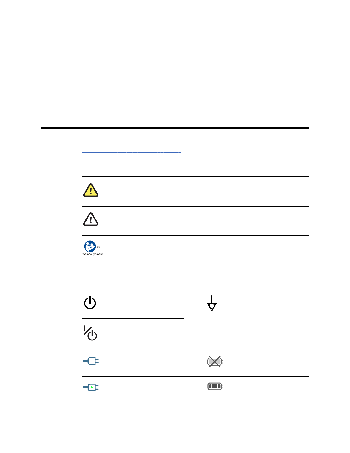
Documentation symbols
WARNING The warning statements in this manual identify conditions or practices that could
lead to illness, injury, or death.
1
Power symbols
CAUTION The caution statements in this manual identify conditions or practices that could
result in damage to the equipment or other property, or loss of data. This definition applies to
both yellow and black and white symbols.
Follow the operating instructions/directions for use (DFU) — mandatory action.
A copy of the DFU is available on this website.
A printed copy of the DFU can be ordered from Welch Allyn for delivery within 7 days.
Power on/Display power-saving
[recent models]
Power on/Display power-saving
[older models]
(on the display) monitor is plugged
into Alternating Current power
Equipotential terminal
Battery absent or faulty
(on the monitor, green indicator)
Alternating Current power present,
battery fully charged
Battery charge level
Page 8
2 Symbols Welch Allyn Connex® Vital Signs Monitor 6000 Series™
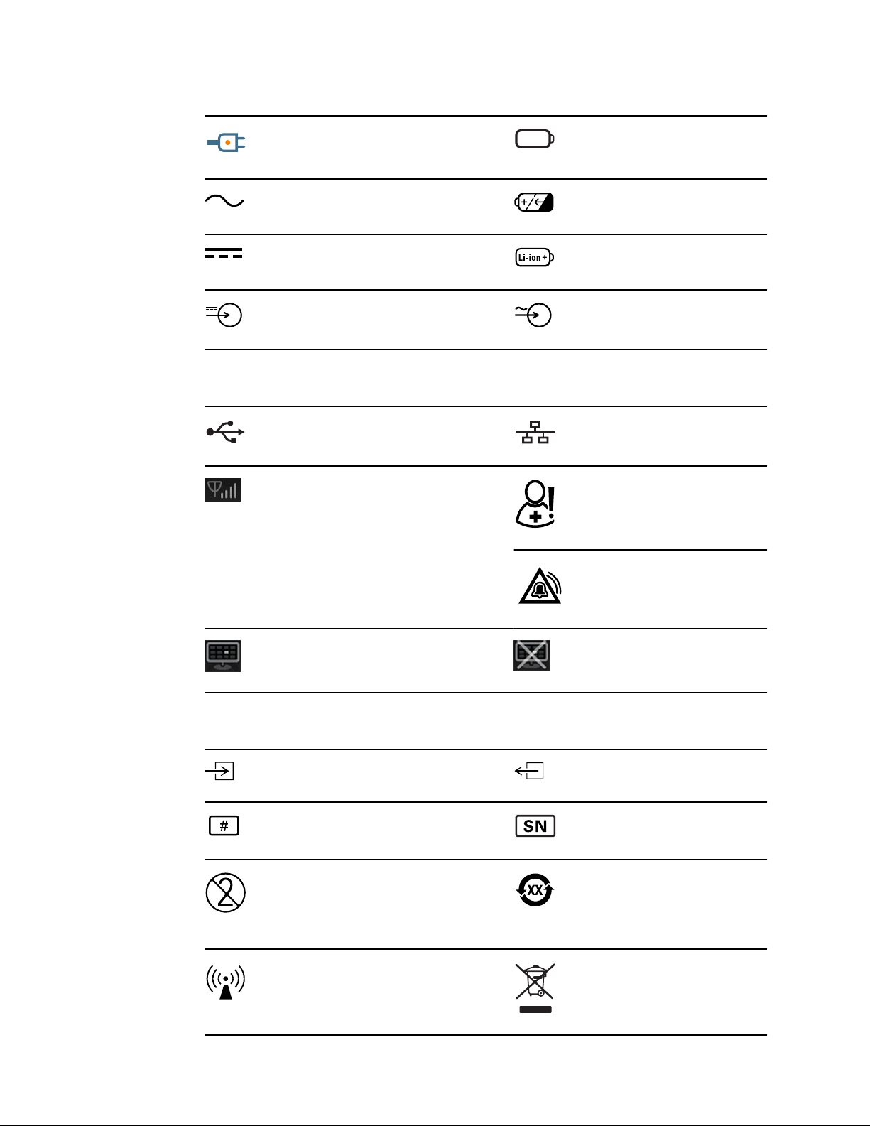
(on the monitor, amber indicator)
Alternating Current power present,
battery is charging
Alternating Current (AC) Rechargeable battery
Direct current (DC) Li-ion battery
Rated power input, DC Rated power input, AC
Connectivity symbols
USB
Wireless signal strength
• Best (4 bars)
• Good (3 bars)
• Fair (2 bars)
• Weak (1 bar)
• No signal (no bars)
• No connection (blank)
Battery cover
Ethernet RJ-45
Nurse call
[recent models]
Nurse call
[older models]
Connected to central station Disconnected from central station
Miscellaneous symbols
CO2 sampling input
Reorder number Serial number
Do not reuse China RoHS markings for control of
Nonionizing electromagnetic
radiation
CO2 sampling output/exhaust
pollution caused by electronic
information products. XX indicates
Environmentally Friendly Use
Period in years.
Recycle the product separate from
other disposables
Page 9
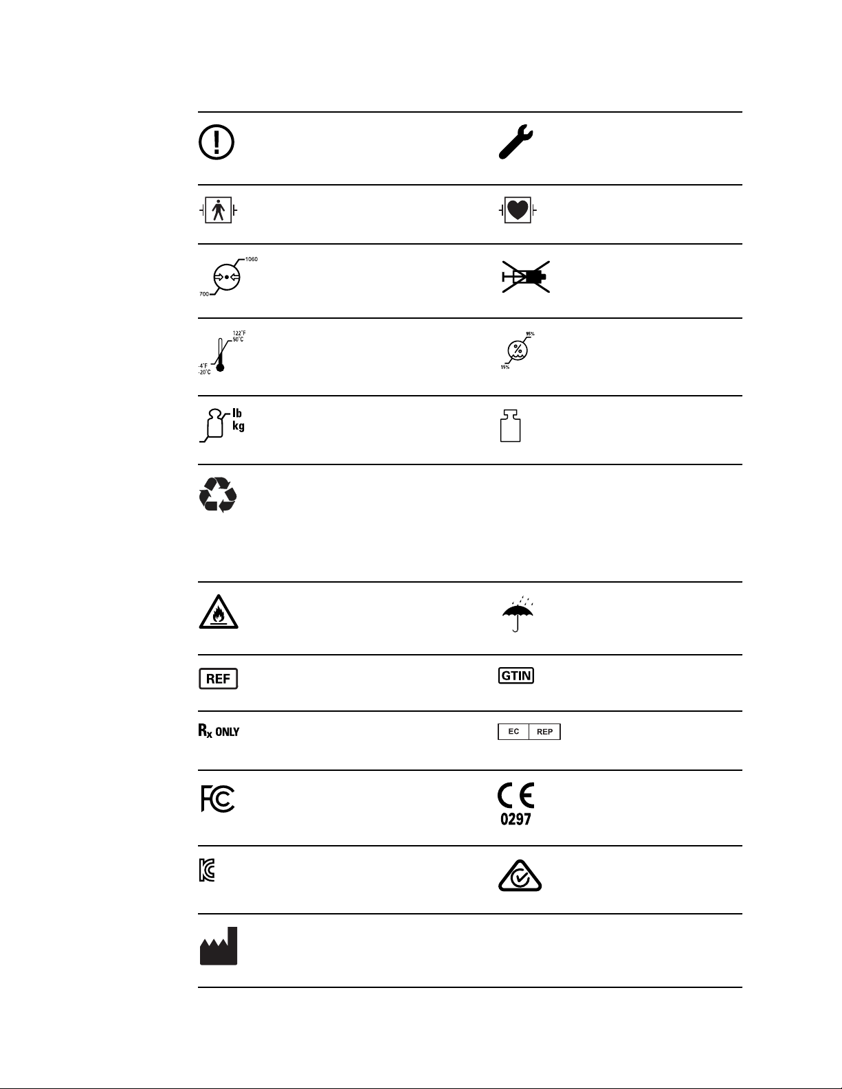
Service manual Symbols 3
Restrictions for use of wireless
device in Europe. European
Community's Class 2 radio
equipment.
Defibrillation-proof Type BF applied
parts
Atmospheric pressure limitation Not for injection
Transport and storage temperature
range
Maximum safe working load limits
(specific values presented with
symbol)
Recycle
IPX1
(Vital Signs
Monitor)
IPX0
(Integrated Wall
System)
Call for maintenance
Defibrillation-proof Type CF applied
parts
Humidity limitation
Mass in kilograms (kg)
Degree of protection provided by
the enclosure with respect to
harmful ingress of liquids
Do not expose to open flame Keep dry
Product identifier Global Trade Item Number
Prescription only or "For Use by or
on the order of a licensed medical
professional"
FCC logo Meets essential requirements of
KC mark Australian Communications and
Manufacturer
Authorized Representative of the
European Community
European Medical Device Directive
93/42/EEC
Media Authority (ACMA) Radio
Compliance Mark (RCM)
Page 10

4 Symbols Welch Allyn Connex® Vital Signs Monitor 6000 Series™
Page 11
Safety
5
All users of the monitor must read and understand all safety information presented in
this manual before using or repairing the monitor.
United States federal law restricts this device to sale, distribution, or use by or on the
order of a licensed medical practitioner.
Warnings and cautions
WARNING Safety risk. Make frequent electrical and visual checks on
cables, sensors, and electrode wires. All cables, sensors, and electrode
wires must be inspected and properly maintained and in proper working
order to allow the equipment to function properly and to protect patients.
WARNING Safety risk. Place the system and accessories in locations
where they cannot harm the patient should they fall from a shelf or mount.
WARNING Fire and explosion hazard. Do not operate the system in the
presence of a flammable anesthetic mixture with air, oxygen, or nitrous
oxide; in oxygen-enriched environments; or in any other potentially
explosive environment.
WARNING Inaccurate measurement risk. Dust and particle ingress can
affect the accuracy of blood pressure measurements. Use the system in
clean environments to ensure measurement accuracy. If you notice dust or
lint build-up on the system’s vent openings, have the system inspected and
cleaned by a qualified service technician.
WARNING Defective batteries can damage the device. If the battery
shows any signs of damage or cracking, replace it immediately, and only
with a battery approved by Welch Allyn.
CAUTION Before disassembling the device or installing options,
disconnect the patient from the system, power down the device, and
disconnect the AC power and any attached accessories (for example, SpO2
sensors, blood pressure hoses and cuffs, and temperature probes) from
the device.
CAUTION To ensure that the system meets its performance
specifications, store and use the system in an environment that maintains
the specified temperature and humidity ranges.
Page 12
6
Safety Welch Allyn Connex® Vital Signs Monitor 6000 Series™
CAUTION The system may not function properly if dropped or damaged.
Protect it from severe impact and shock. Do not use the system if you
notice any signs of damage.
CAUTION Do not connect more than one patient to a system or connect
more than one system to a patient.
CAUTION Do not operate the system in the presence of magnetic
resonance imaging (MRI) or hyperbaric chambers.
CAUTION Do not autoclave the system. Autoclave accessories only if the
manufacturer’s instructions clearly approve it.
General safety considerations
• If the monitor detects an unrecoverable problem, it displays an error message. For
more information see “Troubleshooting.”
• To ensure patient safety, use only accessories recommended or supplied by Welch
Allyn. (See the accessories list on the user documentation CD or
www.welchallyn.com.) Always use accessories according to your facility’s standards
and according to the manufacturer’s recommendations and instructions. Always
follow the manufacturer’s directions for use.
• Welch Allyn recommends that only Welch Allyn service personnel or an authorized
repair center perform warranty service. Performing unauthorized service on a device
that is within warranty may void the warranty.
Electrostatic discharge (ESD)
CAUTION Electrostatic discharge (ESD) can damage or destroy electronic
components. Handle static-sensitive components only at static-safe
workstation.
CAUTION Assume that all electrical and electronic components of the
monitor are static-sensitive.
Electrostatic discharge is a sudden current flowing from a charged object to another
object or to ground. Electrostatic charges can accumulate on common items such as
foam drinking cups, cellophane tape, synthetic clothing, untreated foam packaging
material, and untreated plastic bags and work folders, to name only a few.
Electronic components and assemblies, if not properly protected against ESD, can be
permanently damaged or destroyed when near or in contact with electrostatically
charged objects. When you handle components or assemblies that are not in protective
bags and you are not sure whether they are static-sensitive, assume that they are staticsensitive and handle them accordingly.
Page 13

Service manual Safety 7
• Perform all service procedures in a static-protected environment. Always use
techniques and equipment designed to protect personnel and equipment from
electrostatic discharge.
• Remove static-sensitive components and assemblies from their static-shielding bags
only at static-safe workstations—a properly grounded table and grounded floor mat—
and only when you are wearing a grounded wrist strap (with a resistor of at least 1
megohm in series) or other grounding device.
• Use only grounded tools when inserting, adjusting, or removing static-sensitive
components and assemblies.
• Remove or insert static-sensitive components and assemblies only with monitor
power turned off.
• Insert and seal static-sensitive components and assemblies into their original staticshielding bags before removing them from static-protected areas.
• Always test your ground strap, bench mat, conductive work surface, and ground
cord before removing components and assemblies from their protective bags and
before beginning any disassembly or assembly procedures.
Page 14

8 Safety Welch Allyn Connex® Vital Signs Monitor 6000 Series™
Page 15

Overview
Purpose and scope
This manual is a reference for periodic preventive maintenance and corrective service
procedures for the Welch Allyn Connex Vital Signs Monitor 6000 Series, firmware
versions 2.0X–2.4X. It is intended for use only by trained and qualified service personnel.
Corrective service is supported to the level of field-replaceable units. These include
circuit-board assemblies and some subassemblies, case parts, and other parts.
9
Find instructions for functional testing and performance verification in the Welch Allyn
Service Tool help files.
This manual applies only to this device. For servicing of any other device, see the service
manual for the specific device.
Service work not described in this manual must be performed by qualified service
personnel at the factory or at an authorized Welch Allyn service center.
Related documents
When using this manual, refer to the following:
•
Welch Allyn Connex® Devices Directions for use, Software version 2.4X
(on the user documentation CD)
• Welch Allyn Service Tool
http://www.welchallyn.com/en/service-support/service-center/service-tool.html
• Welch Allyn Service Tool Installation and configuration guide
http://www.welchallyn.com/en/service-support/service-center/service-tool.html
• Welch Allyn Braun ThermoScan® PRO 6000 Ear Thermometer, Service manual
click here to download the PDF
• Welch Allyn 9600 Plus Calibration Tester Directions for use
• Welch Allyn Radio Configuration guide click here to download the PDF
• Welch Allyn website: www.welchallyn.com
CAUTION No component-level repair of circuit boards and subassemblies
is supported. Use only the repair procedures described in this manual.
WARNING When performing a service procedure, follow the instructions
exactly as presented in this manual. Failure to do so could damage the
device, invalidate the product warranty, and cause serious personal injury.
Page 16

10 Overview Welch Allyn Connex® Vital Signs Monitor 6000 Series™
Technical support services
Welch Allyn offers the following technical support services:
• Telephone support
• Loaner equipment
• Service agreements
• Service training
• Replacement service parts
• Product service
For information on any of these services, go to www.welchallyn.com.
Service loaners
For warranty or non-warranty repairs not covered under a support agreement, loaners are
available for a nominal charge, subject to availability. Payment is required prior to
shipment for all loaners not covered under a support agreement.
Welch Allyn Service Centers that provide repair service for this product can, on request,
loan a device for use while the device is being repaired. Loaned devices are provided
free of charge for products repaired while under a support agreement that includes a
free loaner provision.
Loaner equipment for the individual component modules is not available.
Service options
Partners in Care service agreements
While product warranties provide basic assurance of Welch Allyn hardware quality, they
may not include the full range of services and support you need. Welch Allyn offers
premium service and support through our Partners in Care program. Whether you
service your own devices and require a minimum of support or rely on us to service your
device, Welch Allyn provides a program that will meet your needs. A list of available
service and support agreements is presented in the "Field replaceable units" section of
this manual.
For more information, call your sales representative or visit our website:
http://www.welchallyn.com/en/service-support.html.
Warranty service
All repairs on products under warranty must be performed or approved by Welch Allyn.
Refer all warranty service to Welch Allyn Product Service or another authorized Welch
Allyn Service Center. Obtain a Return Material Authorization (RMA) number for all returns
to Welch Allyn Product Service from our website:
http://www.welchallyn.com/en/service-support/submit-a-repair.html.
CAUTION Unauthorized repairs will void the product warranty.
Page 17

Service manual Overview 11
Non-warranty service
Welch Allyn product service and authorized service centers support non-warranty repairs.
Contact any Welch Allyn regional service center for pricing and service options.
Welch Allyn offers modular repair parts for sale to support non-warranty service. This
service must be performed only by qualified end-user biomedical/clinical engineers using
this service manual.
Service training is available from Welch Allyn for biomedical/clinical engineers. Follow
this link for more information.
Repairs
A Welch Allyn Service Center must perform all repairs on products under warranty,
unless you have purchased a Welch Allyn Partners in Care Biomed agreement allowing
you to service the device while under warranty.
CAUTION Unauthorized repairs will void the product warranty.
Qualified service personnel or a Welch Allyn Service Center should repair products out of
warranty.
If you are advised to return a product to Welch Allyn for repair or routine maintenance,
schedule the repair with the service center nearest you.
Welch Allyn Technical Support
If you have a problem with the device that you cannot resolve, call the Welch Allyn
Technical Support Center nearest you for assistance. A representative will assist you in
troubleshooting the problem and will make every effort to solve the problem over the
phone, potentially avoiding an unnecessary return.
To expedite response to your issue, be prepared to provide details on how (steps
executed) and when (time and date) the problem occurred. Also, log and configuration
files captured on the device can assist with diagnosis and troubleshooting. You can
easily save these files from the device to a flash drive using controls on the Service tab.
See the "Service menu" section of this manual for details.
If your product requires warranty, extended warranty, or non-warranty repair service, a
Welch Allyn Technical Support representative will record all necessary information to
issue an RMA number. The support representative will provide you with the address of
the Welch Allyn Service Center to send your device to.
Technical support is available during local business hours.
Returning products
When returning a product to Welch Allyn for service, ensure that you have the following
information:
Product name, model number, and serial number. This information may be found on
•
the product and serial number labels on the bottom of the device.
Page 18

12 Overview Welch Allyn Connex® Vital Signs Monitor 6000 Series™
• A complete return shipping address.
• A contact name and phone number.
• Any special shipping instructions.
• A purchase order number or credit card number if the product is not covered by a
warranty.
• A Partners in Care contract number if product is covered under a service agreement.
• A full description of the problem or service request.
1. Obtain an RMA number:
• Visit us on the web at www.welchallyn.com/customer-self-service.htm, or
• Contact Welch Allyn to make a request.
Note Welch Allyn does not accept returned products without an
RMA.
2. Ship the device to Welch Allyn, observing these rules:
a. Remove from the package the battery, all hoses, connectors, cables, sensors,
power cords, and other ancillary products and equipment, except those items
that might be associated with the problem.
b. Follow shipping and handling requirements regarding Lithium-ion batteries to
comply with new IATA regulations.
Requirements for returning Lithium-ion batteries
• Remove the Lithium-ion battery from the device. You cannot ship these
devices with batteries installed.
• Follow packaging requirements (presented next in this section).
• Do not ship any battery that has been physically damaged or shows signs of
leakage.
• Do not ship any battery that has been recalled by the supplier or
manufacturer.
• Do not ship any waste batteries that should be recycled or discarded.
• Do not ship multiple batteries together.
• Use ground transportation only to ship Lithium-ion batteries.
Packaging requirements for Lithium-ion batteries and associated devices
• Use packaging provided by Welch Allyn or the battery manufacturer to pack
the battery. Seal the battery in the anti-static bag and place it in the shipping
box. Return shipments without approved packing materials will not be
accepted.
Page 19

Service manual Overview 13
Note If the original shipping carton or replacement battery
shipping box is unavailable, consult the manufacturer
website for information regarding shipping Lithiumion batteries:
http://www.iata.org/lithiumbatteries
• If returning both the battery and the device, pack the battery and the device
separately.
• If returning multiple batteries, pack and ship each battery individually. Do not
consolidate multiple batteries in a single package.
c. Clean the device.
Note To ensure safe receipt of your device by the service
center and to expedite processing and return of the
device to you, thoroughly clean all residues from the
device before you ship it to Welch Allyn. For
decontamination and cleaning requirements, see the
appendices.
If a returned device is found to be contaminated with
bodily fluids, it will be returned at the owner’s expense.
United States federal regulations prohibit the processing
of any device contaminated with blood-borne pathogens.
Welch Allyn thoroughly cleans all returned devices on
receipt, but any device that cannot be adequately
cleaned cannot be repaired.
d. Pack the device. Put the device, enclosed in a plastic bag with a packing list,
into the original shipping carton with the original packing materials or into
another appropriate shipping carton, and seal appropriately for shipping.
Remember that batteries must be removed from devices before packing and
shipping them for return.
e. Write the Welch Allyn RMA number with the Welch Allyn address on the outside
of the shipping carton.
WARNING Safety risk. Do not ship any battery that has
been physically damaged or shows signs of leakage
unless you receive specific instructions which meet the
requirements for the shipment of Lithium batteries.
Dispose of damaged or leaking batteries in an
environmentally safe manner consistent with local
regulations.
WARNING Safety risk. Do not pack a defective battery
in checked or carry-on baggage if traveling by air.
Note In the United States, the applicable regulations can be
found in the Code of Federal Regulations (CFR). Refer to
49 CFR 173.185 for shipping lithium batteries by air or
ground. Use 49 CFR 172.102 sections 29, 188, 189, A54,
A55, A100, A101, A103, and A104 to find the special
provisions for shipping lithium batteries.
Page 20

14 Overview Welch Allyn Connex® Vital Signs Monitor 6000 Series™
Recommended service intervals
To confirm that the device is functioning within the design specifications, perform
periodic service as indicated in the following table. Customers who have the Standard
unlicensed edition of the Welch Allyn Service Tool can perform the basic functional
verification and calibration procedures referenced in the table by following the
instructions in this manual. If you have the Gold licensed edition of the service tool, use
the tool to perform a complete functional verification and calibration of the device in lieu
of performing the basic tests.
Component Service interval Service procedure
NIBP module Annually Basic functional verification
SpO2 module Annually Basic functional verification
SpHb parameter Annually Basic functional verification
EarlySense module N/A N/A
RRa parameter N/A N/A
CO2 module
SureTemp Plus Annually Basic functional verification
ECG N/A N/A
Braun ThermoScan PRO 6000 Annually Basic functional verification
Braun ThermoScan PRO 4000 Annually Basic functional verification
Battery 300 charge cycles Replace the battery
1
Initially calibrate the module after 1200 operating hours, then once a year or after 4000 operating hours,
whichever comes first. The initial calibration should not occur before 720 hours of use. If the initial calibration
is done before 720 hours of use, the module will reset to require its next calibration after 1200 hours, instead
of after 4000 hours.
1
Annually or 1200 hours (whichever
comes first)
Annually or 4000 hours (whichever
comes first)
30,000 hours Replace the module
Calibration (first time only)
Calibration
Use the service tool, Gold licensed edition, to perform a complete functional verification
and calibration of the device whenever any of the following conditions exist:
Based on the basic functional verification, the device does not meet specifications
•
• The device has been dropped or otherwise damaged
• The device is malfunctioning
• The case has been opened
• An internal part has been replaced (battery excluded)
Note For instructions on using the Gold licensed edition, see the service tool
help files.
Page 21

Service manual Overview 15
Maintenance
For device maintenance information, see “Maintenance and service” in the device’s
directions for use. Covered topics include the following:
• Replacing the printer paper
• Inspecting and cleaning the device and accessories
• Changing the battery
The Welch Allyn Service Tool
The Welch Allyn Service Tool is available in the following editions:
• Standard unlicensed: Download from http://www.welchallyn.com/service tool.
• Gold licensed: Required to perform complete functional verification and calibration.
This edition requires an additional license. For more information about acquiring this
license, contact Welch Allyn.
Note To qualify for the Gold license, you must attend the
Welch Allyn technical training course or complete online
training for the device.
Clinicians and technical service personnel can use the service tool to manage and
maintain supported Welch Allyn products. You can use the service tool to do the
following:
•
Review device information. When connected to the device, the service tool lists
installed modules, installed firmware and hardware versions, warranty and repair
information, status, and usage history.
• Receive notifications when periodic maintenance is needed. The service tool can
help you manage and maintain your entire inventory of supported Welch Allyn
products. Through the remote service function, the service tool can connect to
Welch Allyn Customer Service. With this functionality you can automatically receive
firmware updates and feature upgrades for your supported products, including
software upgrades for the service tool.
• Install updates and upgrades. The service tool can read the firmware version for
each module and check for available updates or upgrades.
• Create a work list. The work list provides information about service actions—
referred to as work orders—that are waiting for you to perform on your maintained
devices. Work orders may include periodic calibrations, upgrades, or license
installations.
• Schedule periodic maintenance. You can use the service tool to set the service
interval for each maintained device.
• View and save logs. You can download and save log files from the device for
analysis to help diagnose and identify reported issues.
• Create user accounts. Administrators can create user accounts and set permission
levels to control access to the features, allowing one group to perform administrative
tasks and another to perform service tasks. Restricting access prevents the service
tool from being used to make unauthorized changes on a connected device.
• Perform functional verification and calibration. The service tool can check any
device requiring calibration and, if necessary, calibrate the device to match the
design specifications. This feature is not supported for all products and requires the
service tool, Gold licensed edition, for each supported product.
Page 22

16 Overview Welch Allyn Connex® Vital Signs Monitor 6000 Series™
• Recover devices. In the rare case where a device can no longer boot because of
corrupted firmware, the service tool can connect the device to Welch Allyn Technical
Support to reinstall the firmware.
• Extensible. The service tool software accepts new plug-ins to support future Welch
Allyn products.
Some of these features are enabled for any user (Standard unlicensed edition). Others
require special user account privileges or a Welch Allyn service contract (Gold licensed
edition). If you require gold-level support for a Welch Allyn product, please contact
Welch Allyn technical support.
Battery performance
About the battery
The device uses a rechargeable Lithium-ion smart battery. Internal circuitry enables the
battery to report its condition to the device. The device displays the battery status via the
LED power indicator, icons on the screen, and status messages appearing in the Device
Status area of the display. Battery information may be collected using the service tool.
New batteries are shipped from the manufacturer with a 30 percent charge to extend
shelf life. When installing a new battery in the device, you must plug the device into AC
power to wake up the battery. If the AC power is not applied to the device, the new
battery will appear discharged.
The Device Status area displays a low-battery status message when 30 minutes of
power remain and again when 5 minutes remain.
Battery charging is provided by the device’s internal power supply.
For a complete list of battery specifications, see the device’s directions for use.
Best practices
The following practices help to extend the life of the battery and the device.
• Whenever possible, keep the monitor plugged in to charge the battery.
• Remove the battery when storing the device for an extended amount of time.
• Replace batteries that trigger a low battery status message when fully charged.
• Do not use damaged or leaking batteries.
• Store batteries with a 30 to 50 percent charge.
• Store batteries within the temperature range indicated for each period:
WARNING Safety risk. When handling and storing Lithium batteries: Avoid
mechanical or electrical abuse. Batteries may explode or cause burns, if
disassembled, crushed, or exposed to fire or high temperatures. Do not
short or install with incorrect polarity.
○
For storage less than 30 days: Maintain temperature between –4 °F and 122 °F
(–20 °C and 50 °C).
○
For storage between 30 days and 90 days: Maintain temperature between –4 °F
and 104 °F (–20 °C and 40 °C).
Page 23

Service manual Overview 17
○
For storage more than 90 days up to 2 years: Maintain temperature between –4
°F and 95 °F (–20 °C and 35 °C).
• Recycle batteries where ever possible. In the United States call 1-877-723-1297 for
information about recycling your Lithium-ion battery or go to the Call2Recycle
website at http://www.call2recycle.org for additional information.
• When recycling is not an option dispose of batteries in an environmentally safe
manner consistent with local regulations.
Factors affecting battery operating time
The following settings and conditions affect the battery operating time:
• The display brightness setting
• The display power-saver setting
• The device power-down setting
• Frequency and duration of alarms and alerts
• Amount of motion artifact during NIBP measurements
• Radio searching for an access point
Page 24

18 Overview Welch Allyn Connex® Vital Signs Monitor 6000 Series™
Page 25
Controls, indicators, and connectors
The following diagrams show a full-featured monitor. Your monitor, based on size or
configuration, might not contain all of these features.
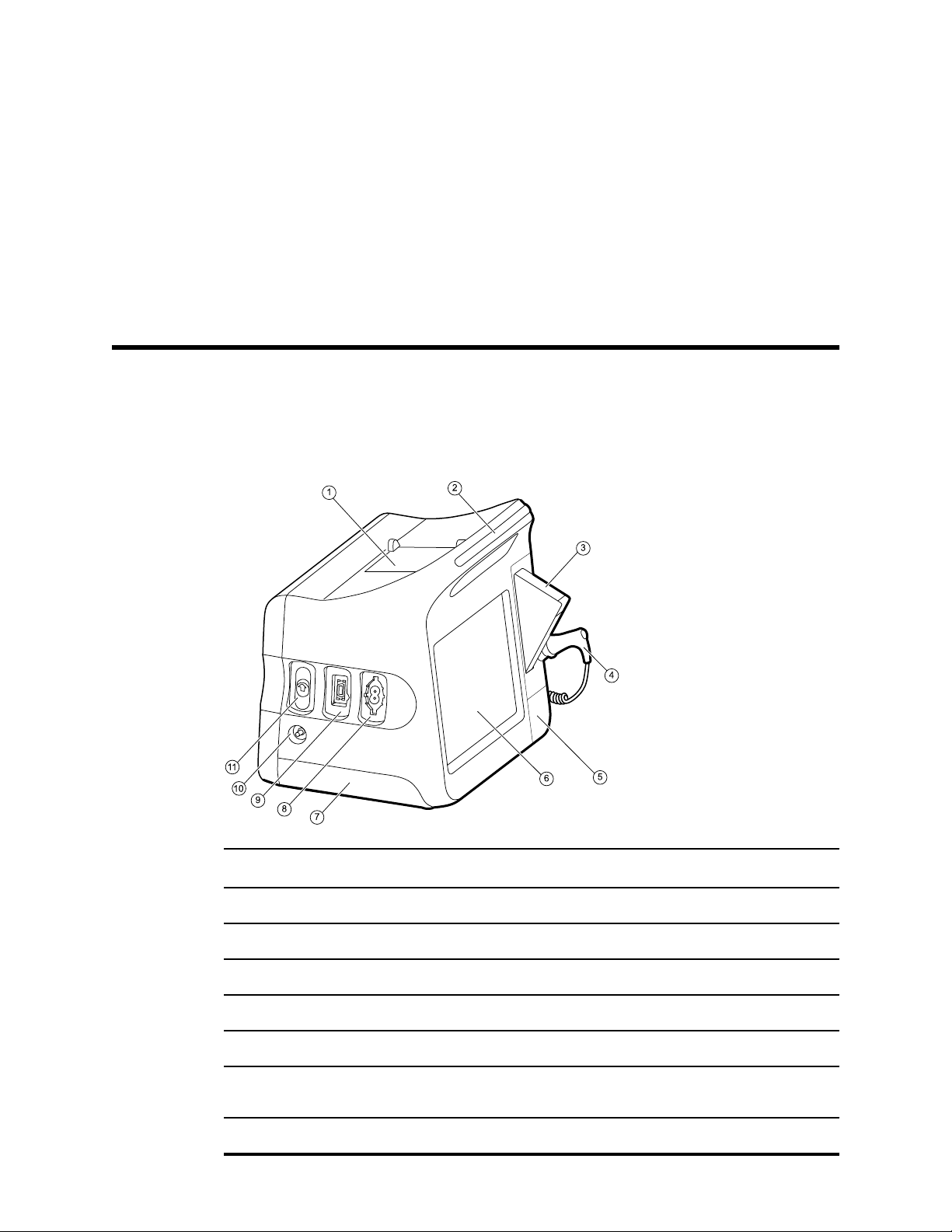
Top-Left-Front view
19
No. Feature Description
1 Printer Printer provides a printout of patient and device information.
2 Light bar Provides a visual alarm with red and amber LEDs.
3 Thermometry Temperature probe cover box.
4 Thermometry Temperature probe.
5 Thermometry (connector behind cover) Secures the probe connection to the monitor.
6 LCD screen 1024 x 600 pixels color touchscreen provides a graphical user
interface.
7 Battery compartment (behind cover) Houses the lithium-ion battery.
Page 26
11
7
10
1
2
3
4
5
6
8
9
13
12
20 Controls, indicators, and connectors Welch Allyn Connex® Vital Signs Monitor 6000 Series™
No. Feature Description
8 Blood pressure Supports dual-lumen or single-lumen hoses.
9 Pulse oximetry
10 CO2 CO2 sampling exhaust port.
11 CO2 CO2 sampling input connector (behind cover).
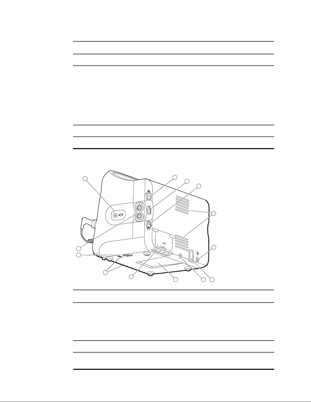
Right-Back-Bottom view
Nellcor or Masimo rainbow SET module.
The Nellcor module measures SpO2 and pulse rate.
The Masimo module measures SpO2, pulse rate, SpHb, and RRa.
Note
SpHb and RRa are optional parameters but
cannot be configured together.
Note
Monitors configured with RRa cannot be
configured with CO2.
No. Feature Description
1 Power switch and LED Power-on/Display power-saving button.
The LED indicates the charging status when the monitor is
connected to AC power:
• Green: The battery is charged.
• Amber: The battery is charging.
2 Ethernet RJ-45 Provides a hardwired connection to the computer network.
3 USB client Provides a connection to an external computer for testing and
software upgrades.
Page 27

Service manual Controls, indicators, and connectors 21
No. Feature Description
4 Nurse call Provides a connection to the hospital nurse call system. (Not
available on the 6300 model.)
5 Fan exhaust
6 Ground lug (equipotential terminal) Provided for electrical safety testing and as a means for
connection of a potential-equalization conductor.
7 Power connection Provides an external AC power connection.
8 Mobile stand mounting hardware Secures the mounting plate to the monitor.
9 Recess for mounting plate Secures the monitor when the monitor is mounted on the mobile
stand or wall.
10 USB connector door Provides access to host USB connections for optional
accessories.
11 Fan intake
12 Speaker Provides tones.
13 Patient movement
The EarlySense module monitors patient movement, respiration
(RR), and pulse rate.
Note
Monitors configured with RRa and CO2 cannot
be configured with EarlySense.
Page 28

22 Controls, indicators, and connectors Welch Allyn Connex® Vital Signs Monitor 6000 Series™
Page 29
Service menu
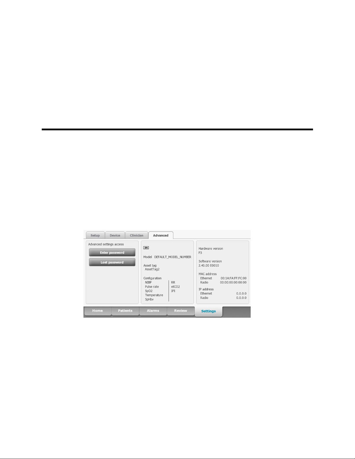
Advanced settings and Service tabs
The Advanced tab provides password-protected access to the monitor's Advanced
settings (or Admin mode), enabling nurse administrators, biomedical engineers, and/or
service engineers to configure specific features. The Advanced tab also presents readonly information about the monitor.
23
The password to enter Advanced settings is configurable and can also be set to expire.
See the "Password" topic at the end of this section for more details.
Note You cannot enter Advanced settings if sensors or physiological alarms are
active or if vital sign measurements are displayed.
General tab
Restore factory default settings
Note This process deletes the custom data file. All custom data will be lost.
1. Go to the Service tabs as described in “Access the Service tabs.”
2. Touch the General tab.
3. Restore factory default settings:
• To restore radio settings to factory default values, touch Radio settings.
• To restore all current settings to factory default values, touch All settings.
• To delete all root certificates currently installed, touch Root CA certificates.
Page 30

24 Service menu Welch Allyn Connex® Vital Signs Monitor 6000 Series™
A confirmation dialog appears.
4. Touch OK.
The factory default settings are restored.
If you selected Radio settings, the radio reboots, and the device remains powered
on.
If you selected All settings or Root CA certificates, the device reboots.
Save the device configuration or custom data to a drive
You can save the device configuration or custom data (custom modifiers and custom
scoring) to a USB flash drive. You can use the saved configuration to restore the device’s
configuration or to copy this configuration to use on other devices. You can use the
saved custom data to restore custom modifiers or custom scores, or you can copy them
to another device.
Note Not all flash drives are supported.
Note When saving the device configuration, the location ID and asset tag
information are not included in the configuration file.
Note Save to USB does not support saving root CA and wireless certificates.
1. Connect a flash drive to the USB port.
2. Go to the Service tabs as described in “Access the Service tabs.”
3. Touch the General tab.
4. Touch Save to USB.
A confirmation dialog appears. You can save the device configuration or custom data
if either custom scores or custom modifiers are present.
5. Touch OK.
If the selected file or files already exist on the USB flash drive, a popup dialog
appears with the message "Device configuration file already exists. Select OK to
continue with save and overwrite existing file or cancel."
6. Touch OK to save the data to the USB drive or touch Cancel to exit without saving.
A confirmation message appears.
Note If the USB drive is incompatible, the message "Unable to save configuration
to USB" appears. Touch OK to continue.
Note The configuration file is saved as CONFIG.PMP. The custom data file is
saved as CUSTOMDATA.XML.
Load a device configuration, custom data, and/or root CA certificates
You can load a configuration from a USB flash drive to the device.
Note
Note If your configuration includes radio parameters, make sure the radio is
Not all flash drives are supported.
enabled. The radio must be enabled before you can import radio
parameters.
Page 31

Service manual
Service menu 25
Note If a device setting is not available in the configuration file, the setting
returns to the factory default. This might be the case when the
configuration file was saved from a device with a different firmware
version.
Note Configuration files cannot be cloned between devices with different host
software, except where the version change is minor.
1. Connect a flash drive to the USB port.
2. Go to the Service tabs as described in “Access the Service tabs.”
3. Touch the General tab.
4. Touch Configure from USB.
A confirmation dialog appears.
5. Select Device configuration, Custom data XML, and/or Root CA certificates.
A confirmation dialog appears to confirm overwriting the existing configuration.
6. Select OK to proceed, or Cancel to quit.
The configuration from the USB flash drive overwrites the configuration on the
device, and the device reboots.
Note If device configuration data is not present on the USB drive, that option will
be disabled.
Note If custom modifiers are not present on the USB drive, that option will be
disabled.
Note If root CA certificates are not present on the USB drive, that option will be
disabled.
Note If the configuration file is incompatible, an "Unable to read configuration
from USB" message appears. This might be the case if the configuration
file was cloned from a device with different software version.
Note Configuration files can be edited or amended by loading the configuration
file onto the device, making changes to the configuration through the user
interface, and then saving the configuration file.
Note Lamarr radio configurations do not overwrite Newmar radio configurations,
and vice versa. A single configuration file can store configurations for both
Lamarr and Newmar radios. To create this file, first create the configuration
file on a device with one type of radio and save it. Then load the
configuration file on a second device with the other type of radio, configure
the radio, and save the file. The newly saved configuration file includes
both the Lamar and Newmar radio configurations, but the device activates
only the configuration matching the device's radio type.
Delete custom data
To delete custom data, you must restore the monitor to factory defaults. Restoring the
monitor to factory defaults also deletes all configuration settings.
To restore the custom configuration settings, save the configuration file to a drive and
reload the file after restoring factory defaults.
Page 32

26 Service menu Welch Allyn Connex® Vital Signs Monitor 6000 Series™
To determine if custom data is loaded on the device, complete these steps:
1. Go to the Service tabs as described in "Access the Service tabs."
2. Touch the Device tab.
A Custom file line displays the configuration name and the cyclical redundancy check
(CRC) in the Firmware version column.
Enter an asset tag
You can enter an alpha-numeric identifier in the data field to serve as an asset tag for
device identification.
1. Go to the Service tabs as described in “Access the Service tabs.”
2. Touch the General tab.
3. Touch and enter up to 20 characters.
4. Touch OK.
Note If the device language changes, the asset tag remains
unchanged.
Send device information to PartnerConnect
The device sends technical information, such as log files, to PartnerConnect periodically.
You can also manually send this information at any time by following this procedure.
1.
Go to the Service tabs as described in “Access the Service tabs.”
2. Touch the General tab.
3. Touch Sync with server.
Self-tests tab
Calibrate the touchscreen
This tab calibrates the touchscreen, if needed.
1.
Go to the Service tabs as described in “Access the Service tabs.”
2. Touch the Self-tests tab.
3. Touch Start.
a. Touch the location indicated by the device. The device checks the current
calibration. If the location coordinates and touched location match, a Calibration
Confirmation dialog appears. Touch OK to finish.
b. If the locations do not match, a calibration failure dialog appears. Touch
Calibrate, and then touch the screen as indicated. When calibration is complete,
a Calibration Confirmation dialog appears. Touch OK to finish.
Page 33

Service manual Service menu 27
Logs tab
View an error or event log
1. Go to the Service tabs as described in “Access the Service tabs.”
2. Touch the Logs tab.
3. View a log report.
• To view an error log, select Error.
• To view an event log, select Event.
Save error and event logs to a USB flash drive
This feature is available in software versions 1.71.03 and later.
You can save a copy of the error and event logs to a USB flash drive.
Note Not all flash drives are supported.
1. Connect a flash drive to the USB port.
2. Go to the Service tabs as described in “Access the Service tabs.”
3. Touch the Logs tab.
4. Touch Save to USB.
A confirmation dialog appears.
5. Touch OK.
Copies of both log files are saved to the drive.
Device tab
View device and module information
1. Go to the Service tabs as described in “Access the Service tabs.”
2. Touch the Device tab.
Device and module information appears for you to view.
Licensing tab
View device licenses
Note After activating a new license, restart the device to complete the activation
process.
1. Go to the Service tabs as described in “Access the Service tabs.”
2. Touch the Licensing tab.
A list of available licenses appears. Checks indicate installed licenses.
Page 34

28 Service menu Welch Allyn Connex® Vital Signs Monitor 6000 Series™
Password tab
Configure passwords
Note The keyboard for the Password tab is the English keyboard regardless of
the language configured on the device.
Note New passwords must meet length requirements to be accepted as valid.
Note The keyboard for the Password tab does not set the first character to upper
case.
Note If you forget or lose your password, you cannot access the Password tab.
See "Access the Service tabs" at the beginning of this section.
1. Go to the Service tabs as described in “Access the Service tabs.”
2. Touch the Password tab.
3. To change the current password, touch Change password.
a. Enter a new password.
Note The password must have between 8 and 32 characters.
A "Re-enter password" dialog appears.
b. Touch OK and re-enter the new password to confirm the change.
Either a "Successful password change" or "Failed password change" dialog
appears.
c. Touch OK and then proceed as needed. In the case of a failed password change,
either try again or cancel the operation.
4. To lock out a user after 10 consecutive incorrect passwords, touch Enable failed
attempt lockout.
Note The lockout period is 5 minutes.
5. To set an expiration for the current password, touch Enable password expiration,
and then enter the number of days after setting a password that it will expire.
Page 35

Power-up sequence
The system performs a power-on self test (POST) each time the device is powered on.
During power up, the device performs a comprehensive self test of the software. If
software testing is successful, the device then tests internal hardware. If all tests are
successful, the system completes power up and the Home tab appears.
To perform the POST:
1. Disconnect any patient cables connected to the device.
2. Insert a fully charged battery into the device.
3. Upon each power up, confirm the following:
a. The light bar flashes amber.
b. The Welch Allyn startup screen appears.
c. A beep sounds, followed by one chime.
29
Note If no chimes sound, replace the speaker as specified in
“Remove the speaker.”
d. The product line logo appears at the bottom of the screen.
e. If a printer is installed, the paper advances slightly.
f. The Home tab appears.
WARNING Equipment failure risk. The device includes a fan that circulates
air through the device. If the fan does not run when you power up the
device, remove it from use and inform qualified service personnel
immediately. Do not use the device until the problem is corrected.
If the internal self-check is successful, the device shows its normal functions with all
values blank and the device is ready for operation. If the self-check fails, an error
message appears in the Device status area at the top of the screen. If a fault that could
adversely affect the product is detected, the device enters a safe mode and stops
monitoring patients. The device remains in safe mode until it is turned off or until it shuts
down automatically after a period of inactivity.
If a system error is detected, the device becomes inactive until you press or until the
device shuts down automatically. The device displays a system fault message that
contains a wrench icon( ) and a system fault code to aid service personnel and
engineers in diagnosing the problem.
While in safe mode, the red LED bar and the piezo buzzer cycle on and off.
Page 36

30 Power-up sequence Welch Allyn Connex® Vital Signs Monitor 6000 Series™
Page 37

Troubleshooting
This section provides the following tables to help troubleshoot the device.
• Symptoms and solutions: These tables list symptoms you might observe, list
possible causes, and suggest actions that may eliminate the problem.
• Technical alarm messages: These tables list messages generated by the device
software when a problem is detected. The tables explain possible causes and
suggest actions that can resolve the problem.
31
These tables can help you diagnose and fix a problem. They do not replace basic
troubleshooting skills. You must still trace the source of the problem to the board or
module level to decide the best course of action. Welch Allyn does not support
component-level repair to the board or module. For available replacement parts, see
“Field Replaceable Units.”
WARNING Do not perform troubleshooting on a device that is emitting
smoke or exhibits other signs of excessive overheating. Disconnect the
device from AC power and call Welch Allyn Technical Support immediately.
CAUTION Replace parts, components, or accessories only with parts
supplied or approved by Welch Allyn. The use of any other parts can lead to
inferior device performance and will void the product warranty.
Symptoms and solutions
Power
Symptom Possible cause Suggested action
The device does not power up A new battery was installed Connect AC power to wake up
the battery.
The AC power is disconnected Connect AC power.
The power cord is defective Replace the power cord.
The battery is discharged Charge the battery.
The power button is defective Replace the power button.
Page 38

32 Troubleshooting Welch Allyn Connex® Vital Signs Monitor 6000 Series™
Symptom Possible cause Suggested action
An internal connection is faulty Check the power-flex cable
connection at J6 on the main
board.
Check the AC power harness
connections from the IEC
connector to the power supply.
Check the power harness from
the power supply J2 to J30 on
the main board.
Check the battery power harness
from J2 on the battery connector
board to J29 on the main board.
The power supply is defective Check the output voltage on the
power supply. The voltage should
be 15 V ± 0.45V DC. If it is not,
replace the power supply.
Hardware
The battery is defective Charge the battery for 5 hours. If
the battery icon on the display
still shows an empty battery
symbol, replace the battery.
The main board is defective Replace the main board.
The battery doesn’t charge or run
time is low
The battery is defective Charge the battery for 5 hours. If
the battery icon on the display
still shows an empty battery
symbol, replace the battery.
The battery connector board is defective Check the battery connector
board for an open short or broken
connector and replace if
necessary.
The battery has reached the end of its useful life Use the service tool to check
cycle count. If the cycle count
exceeds 300, replace the battery.
Mechanical Symptom Possible cause Suggested action
Noisy fan Dust build up Use canned air to blow dust out
of fan.
Fan is out of balance Replace fan.
Page 39

Service manual Troubleshooting 33
Mechanical Symptom Possible cause Suggested action
Cracks in housing Non-approved cleaning agents Replace plastic housing as
necessary.
Use only approved cleaning
agents.
Display
Symptom Possible cause Suggested action
The touchscreen does not respond Software error Reboot the device. Press and
hold the power button until the
device shuts down.
Note Any configuration settings
not saved as default will be lost.
Press the power button to restart.
The display is blank when the
power is on
The touchscreen is out of calibration In Advanced Settings, touch the
Service > Self-tests tabs, then
recalibrate the screen.
The touchscreen lock is activated To unlock the touchscreen, touch
at the bottom of the screen.
To disable the touchscreen lock,
touch the Settings > Device
tabs, then uncheck Allow
display lock timeout.
An internal connection is faulty Check the connection at J48 on
the main board with display flex
cable.
A display flex cable is broken Replace the touchscreen and
display assembly.
The main board has a faulty touchscreen
controller
Excessive force or prolonged rubbing in an area
of the touchscreen
The device is in Power-Saver mode Wake the display by touching the
Replace the main board.
Replace the touchscreen.
screen or the power button.
The device powered down after a period of
inactivity
An internal connection is faulty Check the display harness
Turn on the device by pressing
the power button. In Advanced
Settings, touch the General >
Display tabs, then set Device
power down to the desired
interval.
connections at the display and
Page 40

34 Troubleshooting Welch Allyn Connex® Vital Signs Monitor 6000 Series™
Symptom Possible cause Suggested action
J19 on the main board. Replace
the cable if damaged.
A cable is damaged Replace the cable.
The display is dim The brightness setting is too low Increase the brightness setting.
Touch the Settings > Device
tabs, touch Defaults, then set
Display brightness to the
desired level.
The display has reached the end of its useful life Replace the display.
User interface
Symptom Possible cause Suggested action
Unable to access advanced
settings or enter the advanced
settings code
Desired profile does not appear in
the Profiles tab
Communication
Symptom Possible cause Suggested action
Cannot communicate through the
USB client connection
Patient monitoring is active or being simulated Discontinue patient monitoring or
stop the simulation.
The parameter alarm is on Dismiss the alarm.
Intervals are turned on Stop intervals.
The profile license is not installed In Advanced settings, touch the
Service > Licensing tabs.
Verify that the profile license box
is checked. If not, purchase the
license and install it using the
service tool.
The profile is not enabled In Advanced settings, touch the
Device tab, then check the
profile(s) you want to enable.
The battery charge is low Connect the device to AC power
and allow the battery to fully
charge.
The communications board does not receive
power
The USB client is defective Test the connection by
Check the voltage from J49 on
the main board for +5.0, ±0.5V
DC. Replace the main board if
necessary.
connecting a PC running the
service tool. Verify that the
service tool is configured
properly on the PC to
Page 41

Service manual Troubleshooting 35
Symptom Possible cause Suggested action
communicate with the device.
See the service tool help files.
Replace the power cable to the
communications board.
USB accessories do not
communicate with the monitor
The device does not communicate
via Ethernet with the computer
network
The accessory is defective Replace with a known good
accessory.
The communications board is not receiving power Check the voltage from J49 on
the main board for +5.0, ±0.5V
DC. Replace the main board if
necessary.
One or more USB host connections are defective Test the connection with a USB
thumb drive. If no power or
enumeration is present, such as
an LED on a thumb drive, replace
the communications board.
A USB connection from the communications
board to the main board is faulty
The device is not configured properly Check the settings with your
The communications board is not receiving power Check the voltage from J49 on
Verify that the USB cables are
connected correctly.
Replace the USB cables.
network administrator.
the main board for +5.0, ±0.5V
DC. Replace the main board if
necessary.
The radio does not connect to the
network
The Ethernet connection from the main board is
faulty
The network Ethernet switches are not set to the
correct speed to work with the device
The cable run to the switch is too long Use a shorter patch cable.
The device is out of range of the access point Check the network status
The device is not configured properly Check the settings with your
The antenna is defective Check the antenna cable and
Test the internal Ethernet cable.
Replace if necessary.
Verify that the shim is installed,
if required, on the Ethernet cable
connector at J11. See the
reassembly notes for the main
board.
Set the switches to 10 Mbps full
duplex.
screen’s RSSI value.
network administrator.
antenna connection. Replace the
cable and antenna if necessary.
Page 42

36 Troubleshooting Welch Allyn Connex® Vital Signs Monitor 6000 Series™
Symptom Possible cause Suggested action
The communications board is not receiving power Check the voltage from J49 on
the main board for +5.0, ±0.5V
DC. Replace the main board if
necessary.
Alarms
Symptom Possible cause Suggested action
The light bar does not turn on No alarm was triggered Verify that the light bar flashes
when the system starts.
Verify that the alarm is triggered
by a visual indicator in the
message status area and an
audio alarm occurs.
There is a faulty connection Check the light-bar harness and
connections at the light bar and
J46 on the main board. Replace
the defective cable if necessary.
The light-bar board is defective Apply +3.3V to pin 1 of the
harness and ground to pin 2.
Verify that the amber LEDs
illuminate. Connect the ground to
pin 3. Verify that the red LEDs
illuminate. If one or both do not
illuminate, replace the LED light
bar.
The main board is defective Verify that there are +3.3V at pin
1 of J46 on the main board.
No audible alarm occurs No alarm was triggered Verify that the alarm is triggered
by a visual indicator in the
message status area and light
bar. Listen for audible sounds on
start up.
The alarm audio is set to Off
The alarm audio is set too low
Touch the Alarms > General
tabs, then select Alarm audio
on.
In Advanced settings, touch the
General > Alarms tabs, then
disable Allow user to turn off
general audio.
Touch the Alarms > General
tabs, then set Volume to the
desired level.
In Advanced settings, touch the
General > Alarms tabs, then
Page 43

Service manual Troubleshooting 37
Symptom Possible cause Suggested action
set Minimum alarm volume to
the desired level.
There is a faulty connection Check the speaker harness and
connections at the speaker and
J12 on the main board. Replace
the defective cable if needed.
The speaker is defective Replace the speaker.
The main board is defective Test speaker output using an
oscilloscope on J12.
NIBP
Symptom Possible cause Suggested action
The NIBP frame on the display is
blank
Patient movement messages
Symptom Possible cause Suggested action
The Movement frame on the
display is unavailable.
The USB cable is defective Replace the USB cable.
The NIBP module is not connected Check the internal USB
connection.
The NIBP module is not functional Check the error logs for NIBP
errors. See the service tool help
files for details on specific errors
and suggested actions.
Check with Welch Allyn for
software updates.
If no NIBP error is logged, the main board might
be defective
A USB cable is defective Replace the USB cable.
The EarlySense module is not connected Check the internal USB
Replace the main board if
necessary.
connection.
The EarlySense module is not functional. Check the error logs for
EarlySense errors. See the
service tool help files for details
on specific errors and suggested
actions
Connect device to a computer
with the Service Tool installed
and an active internet
connection. Search for any
available software updates.
Page 44

38 Troubleshooting Welch Allyn Connex® Vital Signs Monitor 6000 Series™
Symptom Possible cause Suggested action
SpO2
If no error is logged, the main board might be
defective
The selected profile does not support patient
movement monitoring.
Replace the main board if
necessary.
Change the profile to Continuous
Monitoring.
Symptom Possible cause Suggested action
The SpO2 frame on the display is
blank
The USB cable is defective Replace the USB cable.
The SpO2 module is not connected Check the internal USB
connection.
The SpO2 module is not functional Check the error logs for SpO2
errors. See the service tool help
files for details on specific errors
and suggested actions.
Check with Welch Allyn for
software updates.
If no SpO2 error is logged, the main board might
be defective
Replace the main board if
necessary.
SpHb
Symptom Possible cause Suggested action
The SpHb frame on the display is
blank
The SpHb frame is unavailable The selected profile does not support SpHb. Change the profile to Intervals
The UI license is not installed. Purchase a license and install the
license using the service tool.
The wrong sensor is connected. Use a sensor that supports the
SpHb parameter.
The sensor or cable expired. Replace the sensor or cable.
The sensor or cable is defective. Replace the sensor or cable.
The Masimo SpO2 module does not have the
SpHb parameter enabled.
Purchase the parameter and
install using the service tool.
Monitoring or Continuous
Monitoring.
Page 45

Service manual Troubleshooting 39
RRa
Symptom Possible cause Suggested action
CO2
The RRa frame on the display
is blank
The RRa frame is not available. The selected profile does not support RRa. Change the profile to Continuous
The RRa sensor is not connected. Connect an RRa sensor.
The sensor or cable is defective. Replace the sensor or cable.
The UI license is not installed. Purchase a license and install it
using the service tool.
The Masimo module does not have the RRa
parameter enabled.
Purchase the parameter and
install it using the service tool.
Monitoring.
Symptom Possible cause Suggested action
The CO2 frame on the display
is blank
A USB cable is defective Replace the internal USB cable.
The CO2 module is not connected Check the internal USB
connections.
The CO2 module is not functional Check the error logs for CO2
errors. See the service tool help
files for details on specific errors
and suggested actions.
The pump does not activate when
the sampling line is attached
The etCO2 and RR frames are
unavailable.
Check with Welch Allyn for
software updates.
If no CO2 error is logged, the main board might
be defective
The sampling line is not securely attached Screw the sampling line
The input connector is dirty Clean the input connector. See
The selected profile does not support CO2 Change the profile to Continuous
Replace the main board if
necessary.
connector clockwise into the CO2
input connector on the monitor
until it can no longer be turned.
the appendices for instructions.
Monitoring.
Page 46

40 Troubleshooting Welch Allyn Connex® Vital Signs Monitor 6000 Series™
ECG
Symptom Possible cause Suggested action
No LTA alarm associated with
patient injury or death
No LTA or ECG tile shows
Arrhythmia detection off
No ECG pane Module not connected Check ECG module LED.
LTA license not installed Remove device from service,
contact Welch Allyn Technical
V-Tach, V- Fib, Asystole detection disabled
invalid data
Alarms off in advanced settings Turn on alarms.
No license Install license.
ECG module unable to detect arrhythmias Contact Welch Allyn Technical
Faulty patient cable Check cable.
Faulty module cable
CVSM software does not support ECG Update software.
Profile not set to Continuous Monitoring Set profile to Continuous
Support, and return to Welch
Allyn for service.
Support.
Replace the module if necessary.
Monitoring.
ECG tile disabled Patient type set to Neonate Change patient type to Adult or
No waveform Start button not activated
ECG gain too high Reduce ECG gain.
Patient type set to Neonate Change patient type to Adult or
Noisy waveform 50 or 60 Hz filter disabled Enable filter.
Wrong mains filter value selected (50 Hz versus
60 Hz)
Poor lead placement See DFU for proper placement.
Pediatric.
Touch Start on ECG tile to begin
waveform streaming.
Pediatric.
Set the filter to the correct mains
frequency for your location.
Page 47

Service manual Troubleshooting 41
Symptom Possible cause Suggested action
No pacer or ECG tile shows pacer
detection off
No alarming snapshot was autoprinted
Printed waveform is too small ECG gain and/or sweep speed is set too low Increase gain and/or sweep
Snapshot button is disabled An alarming snapshot is in progress Wait for up to one minute for the
Module LED off Module is not receiving power Replace cable.
Pacer detection Off
ECG module unable to detect pacer Contact Welch Allyn Technical
Automatic print on ECG alarm disabled In Advanced settings, touch the
Less than one minute has elapsed between
snapshots
Touch the Settings > Setup
tabs, then touch the ECG vertical
tab. Enable Patient has a
pacemaker.
Support.
Replace the module if necessary.
Parameters tab, then touch the
ECG vertical tab. Enable
Automatic print on ECG alarm.
See printer section for print
failures.
speed and reprint.
button to enable.
Module LED yellow Internal error Power cycle device or disconnect
Module LED steady green Module powered on Working as designed.
Module LED flashing green Sending data Working as designed.
Weight scale
Symptom Possible cause Suggested action
Weight does not appear in manual
parameter frame
and then reconnect cable.
The weight was not selected in Advanced
settings
The weight scale is not licensed Purchase a license and install the
The weight scale is not connected Check cables and connections.
In Advanced settings, touch the
Parameters tab, then select
Weight.
Note You can select only four
manual parameters.
license using the service tool.
Use the service tool to test
connectivity. Replace cables.
The weight scale is not configured Consult the scale directions for
use.
Page 48

42 Troubleshooting Welch Allyn Connex® Vital Signs Monitor 6000 Series™
Temperature
Symptom Possible cause Suggested action
The temperature frame on the
display is blank
The USB cable is defective Replace the USB cable.
The temperature module is not connected Check the internal USB
The temperature module is not functional Check the error logs for
If no temperature error is logged, the main board
might be defective
Braun ThermoScan PRO 4000 thermometer
Symptom Possible cause Suggested action
The thermometer batteries don’t
charge
The dock LED is green, but the
battery is low or depleted
The rechargeable battery pack no longer takes a
charge
Primary AA batteries are installed in the
thermometer
Primary AA batteries are installed in the
thermometer
connection.
temperature errors. See the
service tool help files for details
on specific errors and suggested
actions.
Replace the main board if
necessary.
Replace the rechargeable battery
pack.
Replace the batteries with a
rechargeable battery pack.
Replace the batteries with a
rechargeable battery pack.
The dock is defective Replace the dock.
Thermometer readings do not
transfer to the device
The external USB cable is unplugged Check the external USB
The USB bus has stopped communicating with
the Braun dock. (The device displays wrench error
#00000014.)
Note For additional troubleshooting tips for the thermometer, see the
manufacturer’s product documentation.
Braun ThermoScan PRO 6000 thermometer
Symptom Possible cause Suggested action
Braun measurements are inaccurate Probe lens is displaced Examine lens for displacement. If you
connection.
Reboot the host device.
observe a gap in the seam between the
bezel and the lens, replace the
thermometer.
Page 49

Service manual Troubleshooting 43
Symptom Possible cause Suggested action
Use inconsistent with DFU See DFU for proper operation. Perform
the Braun functional verification test
using the service tool or the manual
test described in this manual. Replace
as necessary.
Ingress of cleaning solutions has
corroded the electronics
Temperature tile displays ++
Braun displays HI
Temperature tile displays - -
Braun displays LO
Braun displays “POS” error The infrared monitor cannot find a
Temperature taken is not within typical
human temperature range. HI will be
displayed when temperature is higher
than 108°F (42.2°C).
Temperature taken is not within typical
human temperature range. LO will be
displayed when temperature is lower
than 68°F (20°C).
temperature equilibrium and allows no
measurement.
Replace the thermometer. Review
cleaning procedures in the DFU.
Change probe cover to reset. Then,
make sure thermometer is properly
inserted and take a new temperature.
Change the probe cover to reset.
Restrict patient movement and ensure
that the positioning of the probe is
correct and remains stable while taking
new temperature.
Braun displays “Err” error Ambient temperature is not within the
allowed operating range (50 – 104 °F
or 10 – 40 °C) or changing too rapidly.
Braun display is blank or displays all
icons
Braun displays Alert icon with “1” in
lower right corner
System error
Technique Compensation (PerfecTemp)
technology is not functioning or
disabled
Wait 20 seconds until thermometer
turns off automatically, then turn on
again. Ensure thermometer and patient
are in an environment for 30 minutes
where the temperature is between 50
°F and 104 °F or 10 °C and 40 °C.
Wait 20 seconds until the thermometer
turns off automatically, then turn on
again. If error persists, reset the
thermometer by removing the batteries
and putting them back in.
If error still persists, batteries are dead.
Insert new batteries.
If error still persists, contact local
Welch Allyn Service Center or
representative.
Open the temperature tab in Advanced
settings to configure PerfecTemp*.
Page 50

44 Troubleshooting Welch Allyn Connex® Vital Signs Monitor 6000 Series™
Symptom Possible cause Suggested action
Braun displays Alert icon with “U” in
lower right corner
C/F button is not functional Celsius only enabled Open the temperature tab in Advanced
Pulse timer button is not functional Pulse timer disabled Open the temperature tab in Advanced
Braun displays lock icon and is
unresponsive
Braun display is blank after performing
upgrade
*Host device Braun 6000 settings override configuration settings from Welch Allyn Service Tool.
Unadjusted Operating Mode is enabled
Security mode enabled and anti-theft
timer has expired
Software upgrade was interrupted Remove and replace the battery while
Open the temperature tab in Advanced
settings to configure Unadjusted
Operating Mode*.
settings to disable Celsius only
selection*.
settings to enable pulse timer*.
Return Braun thermometer to dock to
unlock. Security mode is set on
temperature tab in Advanced settings.
holding the C/F button or return to the
dock while holding the C/F button.
Retry upgrade.
Note For additional troubleshooting tips for the thermometer, see the
Manual parameters
Symptom Possible cause Suggested action
The manual parameter frame does
not appear on the Home tab
BMI is not displayed The BMI parameter is not selected Select the BMI parameter in the
manufacturer’s product documentation.
No manual parameters are selected in Advanced
settings
Height or weight was changed Adjusting the height or weight
Weight scale not connected BMI is available only from a
In Advanced settings, touch the
Parameters tab, then select the
desired manual parameters.
Note You can select only four
manual parameters.
advanced settings.
clears BMI.
weight scale with height.
Page 51

Service manual Troubleshooting 45
Printer
Symptom Possible cause Suggested action
The printer does not print The reactive side of the thermal paper does not
face the print head
The thermal paper is wet Clean and dry the inside of the
The USB cable is defective Replace the USB cable.
The printer module is not connected Check the internal USB and
The printer does not have power Check J17 on the main board. For
The printer module does not function Replace the printer module.
The power harness is defective Test the power harness. Replace
If no printer error is logged, the main board may
be defective
The printer fuse has blown; check MCE printer
fuse F5
Reverse the printer paper.
printer housing and replace the
printer paper.
power harness connection.
more information, see
“Interconnect diagram.”
if necessary.
Check the error logs for printer
errors. Replace the main board if
necessary.
Replace the MCE PCBA.
Barcode reader
Symptom Possible cause Suggested action
The barcode reader powers on but
does not transfer data
The patient ID or clinician ID do not
match
No license is installed Purchase a license and install
the license using the service
tool.
The barcode reader is not programmed to use USB
Com Port Emulation mode
The barcode reader is not supported For Honeywell model 4600g
The barcode scanner did not enumerate properly Power cycle the Connex
The barcode scanner is not programmed to properly
interpret the barcode
Refer to the manufacturer's
documentation to program
the barcode reader to USB
COM Port Emulation mode.
barcode readers, verify that
the PID is set to 020A.
device.
Program the barcode scanner
to turn on required symbology
and to also add or delete
characters to form correct ID.
Page 52

46
Troubleshooting Welch Allyn Connex® Vital Signs Monitor 6000 Series™
Errors
Symptom Possible cause Suggested action
#000000001 An internal software error Power down and restart. If the
error persists, call Welch Allyn
#000000002 An unclassified hardware error
#000000003 Graphics RAM POST
#000000004 System RAM POST
#000000005 Watchdog POST
#000000006 FLASH initiation failed
#000000007 A display system error
#000000008 A real-time clock error
#000000009 An audio system error
Technical Support for service.
#000000010 An Ethernet system error
#000000011 The touchscreen controller failed
#000000012 Five or more SMBUS errors over a 1-minute period
occurred
#000000013 The communications module or main board failed
#000000014 Main board USB hub failure
#000000015 Software watchdog timer reset
Technical alarm messages
This section presents tables of technical alarm and information messages to help you
troubleshoot issues on the device. For information about physiological, dialog, or
informational messages, see the device’s directions for use.
When the device detects certain events, a message appears in the Device Status area at
the top of the screen. Message types include the following:
•
Information messages appear on a blue background.
• Very low-priority alarms appear on a cyan background.
• Low- or medium-priority alarms appear on an amber background.
• High-priority alarms appear on a red background.
Technical alarm messages are low priority or very low priority unless noted in the
Message column.
You can dismiss a message by touching the message on the screen, or, for some
messages, you can wait for the message to time out.
Page 53

Service manual Troubleshooting 47
To use these tables, locate the message that appears on the device in the left column of
the table. The remainder of the row explains possible causes and suggests actions that
can resolve the issue.
If you cannot resolve the issue, use the service tool to read the error log files or use the
service tool to perform a functional test1 on the module reporting the message.
CO2 messages
Message Possible cause Suggested action
CO2 not functional. Call for service. A nonrecoverable communications error has
occurred
Filter line disconnected. The sampling line is not connected to the monitor Connect a sampling line to the
The sampling line is defective Replace the sampling line.
The input connector is dirty Clean the input connector. See
The sampling line detection switch is faulty Replace the module.
Occlusion in gas line. (High-priority
alarm)
The purge cycle failed to clear a blockage in the
sampling line
The purge cycle failed to clear a blockage inside
the module
Check the error logs for CO2
errors. See the service tool help
files for details on specific errors
and suggested actions.
Check with Welch Allyn for
software updates.
monitor.
Check to ensure that the
sampling line plug is tightly
connected to the monitor.
the appendices for instructions.
Replace the sampling line.
Replace the module.
CO2 temperature out of range. CO2
is not calibrated.
Connect or clear filter line. Calibration failed because sampling line is
1
Requires the service tool, Gold licensed edition.
CO2 module temperature is out of range Wait for the module temperature
blocked or kinked
Module is not ready for calibration because the
sampling line is not connected to the monitor
to return to normal and the
module to reset before
calibrating CO2.
Move to a location where the
ambient temperature enables the
module temperature to return to
normal and the module to reset
before calibrating CO2.
Check sampling line for
obstruction or kinks. Replace the
sampling line if necessary.
Check to ensure that the
sampling line plug is tightly
connected to the monitor.
Page 54

48 Troubleshooting Welch Allyn Connex® Vital Signs Monitor 6000 Series™
Message Possible cause Suggested action
Purging filter line. An occlusion was detected in the sampling line,
which automatically initiated a purge cycle
Check calibration gas
concentration.
Check calibration gas flow. The calibration gas flow is unstable Check the sampling line for kinks
Check exhaust port for obstruction. The exhaust port is blocked Verify that the exhaust port is
Calibration overdue. CO2 might not
be accurate.
The calibration gas is not flowing Check that the calibration gas is
The calibration gas has the wrong CO2
concentration
Internal flow problem Replace the module.
The due date for calibration has passed Perform CO2 calibration.
Wait for the purge cycle to clear
the blockage and the module to
be reset.
turned on.
Check that the calibration gas
has the correct concentration.
or obstructions.
Check all tubing connections for
leaks.
Check that the gas source is not
running out.
unobstructed.
Factory service overdue. CO2 might
not be accurate.
Calibration failed. The calibration failed for the reason named in the
Calibration completed successfully. An uninterrupted, error-free calibration took
Calibration aborted. You or some other user interrupted the
Patient movement messages
Message Possible cause Suggested action
Replace the bed sensor. The sensor is faulty or expired. Replace the bed sensor.
The bed sensor is disconnected. The bed sensor is disconnected from the monitor. Check the bed sensor cable to
The due date for factory service has passed Replace the module.
error message
place
calibration
The cable is faulty or expired. Replace the cable.
The bed sensor is disconnected from the
extension cable
Check the error message and
take corrective action presented.
Resume using the monitor.
Resume or retry calibration.
ensure that connections to the
monitor and the extension cable
are tight.
The bed sensor is upside down.
The bed sensor was not placed properly underthe
mattress, mattress cover, or mattress pad
Turn the sensor right-side up.
Page 55

Service manual Troubleshooting 49
Message Possible cause Suggested action
Cannot measure patient. Lost or
unstable signal.
Cannot measure respiration The sensor is not under the patient's chest (Low
The sensor is not under the patient's chest (Low
confidence condition)
The sensor is turned 90 degrees, placed vertically
(Low confidence condition)
There is excessive patient movement (Low
confidence condition)
An unqualified mattress type is in use
confidence condition)
The sensor is turned 90 degrees, placed vertically
(Low confidence condition)
There is excessive patient movement (Low
confidence condition)
An unqualified mattress type is in use Switch to a qualified mattress
The sensor is not under the
patient's chest (Low confidence
condition)
Place the sensor horizontally
under the patient's mattress,
with the cable extending toward
the head of the bed.
Check the patient.
Replace the bed sensor.
Adjust the position of the sensor
under the patient's chest.
Place the sensor horizontally
under the patient's mattress,
with the cable extending toward
the head of the bed.
Check the patient. Replace the
bed sensor. Use an alternative
sensor to monitor respiration.
type.
Cannot measure pulse rate. The sensor is not under the patient's chest (Low
confidence condition)
The sensor is turned 90 degrees, placed vertically
(Low confidence condition)
There is excessive patient movement (Low
confidence condition)
An unqualified mattress type is in use Switch to a qualified mattress
EarlySense is not functional. A module error occurred. Call for service.
Bed sensor expires in… The bed sensor expires soon. Replace the bed sensor before it
The sensor has expired. The bed sensor has expired. Replace the sensor.
The sensor is defective. A sensor error occurred Replace the sensor.
Trend change detected. Review
patient history.
Patient measurements have changed enough to
require attention
Adjust the position of the sensor
under the patient's chest.
Place the sensor horizontally
under the patient's mattress,
with the cable extending toward
the head of the bed.
Check the patient. Replace the
bed sensor. Use an alternative
sensor to monitor pulse rate.
type.
expires.
Check the patient and patient
history.
Page 56

50 Troubleshooting Welch Allyn Connex® Vital Signs Monitor 6000 Series™
RRa messages
Message Possible cause Suggested action
Respiratory freshness timeout
expired.
Replace RRa probe. The sensor is faulty Replace the sensor.
RRa patient interference detected. Poor sensor placement on the patient Remove the sensor from the
Excessive ambient or environmental noise Reduce the level of noise in the
room.
Poor sensor placement on the patient Remove the sensor from the
patient and reapply.
The patient cable or sensor is defective
No sensor is connected Connect the sensor.
The cable is faulty Replace the cable.
The patient is talking
The patient is snoring Gently adjust the patient's
Replace the patient cable or
sensor.
patient and reapply.
Ask the patient to limit talking.
position to reduce snoring.
Awaken and ask the patient to
adjust their position to reduce
snoring.
RRa background interference
detected.
NIBP messages
Message Possible cause Suggested action
Alarm
NIBP air leak; check cuff and tubing
connections.
NIBP not functional. Call for
service.
Excessive ambient or environmental noise Reduce the level of noise in the
room.
The NIBP module has an air leak Check the cuff, tubing, and
connections for leaks. If no leaks
are found, retake the
measurement. If the message
reappears, replace the NIBP
module.
Internal errors or messaging errors occurred Check the error logs for NIBP
errors. See the service tool help
files for details on specific errors
and suggested actions.
Check with Welch Allyn for
software updates.
Page 57

Service manual Troubleshooting 51
Message Possible cause Suggested action
The ambient temperature is out of range Use the monitor in the specified
temperature range.
Unable to determine NIBP; check
connections; limit patient
movement.
Unable to determine NIBP; check
connections and tubing for kinks.
Incorrect NIBP cuff size; check
patient type.
Inflation too quick; check NIBP cuff
and tubing connections.
Unable to determine NIBP; check
inflation settings.
Pressure exceeded the maximum limit for this
patient mode
NIBP tubing on the outside of the device is kinked Check the connections and tubing
The NIBP module needs to be calibrated Perform NIBP calibration.
Tubing inside the NIBP module is kinked Replace the NIBP module.
A neonate cuff is in use with the monitor in adult
or pediatric mode
NIBP inflation was too quick Check the connections and tubing
Target pressure was too low Check inflation settings and
Check connections; limit patient
movement.
Clear the alarm and retry NIBP.
for kinks.
Clear the alarm and retry NIBP.
Check the patient type and cuff
size.
Clear the alarm and retry NIBP.
for kinks.
Clear the alarm and retry NIBP.
change as necessary.
Clear the alarm and retry NIBP.
Change the inflation setting.
Too many attempts Change the inflation setting.
Information
User cancelled NIBP reading. Blood pressure reading cancelled by user
Tube type does not match device
configuration.
(NIBP measurement is available)
Excessive patient movement. The NIBP reading was deemed not precise
The tube type connected to the monitor does not
match the NIBP configuration.
The single lumen switch on the NIBP connection
is stuck
Touch OK to dismiss.
Touch NIBP Start button to
dismiss and restart the NIBP
reading.
Touch OK to dismiss.
Configure the NIBP advanced
settings to match the tube type,
patient type, and algorithm.
Use a small screw driver to press
the switch in and release until
the spring returns the switch to
the dual-lumen position.
Touch OK to dismiss.
Limit patient movement and
restart the NIBP measurement.
Page 58

52 Troubleshooting Welch Allyn Connex® Vital Signs Monitor 6000 Series™
SpO2 and SpHb messages
Message Possible cause Suggested action
Alarm
SpO2 not functional. Call for
service.
Attach SpO2 sensor to monitor. The sensor was not detected Check the sensor connection.
Replace the SpO2 sensor. The sensor is faulty Replace the sensor.
The sensor is defective Replace the SpO2 sensor with a
known good sensor.
An internal error occurred Update the host software to the
current version.
Check the error logs for SpO2
errors. See the service tool help
files for details on specific errors
and suggested actions.
Check with Welch Allyn for
software updates.
Replace the sensor.
The sensor expired (applies only to SpO2 / SpHb
sensors)
No sensor is connected Connect the sensor.
The patient cable is faulty Replace the cable.
Replace the sensor.
Searching for SpO2. (High-priority
alarm)
Low SpO2 signal quality. Check
sensor.
Low SpHb signal quality. Check
sensor.
Low perfusion. Check sensor.
The SpO2 module is faulty Verify module functionality by
replacing the sensor with the
applicable SpO2 tester. If the
message persists after you have
installed the SpO2 tester, replace
the module.
The SpO2 sensor is not attached to the patient’s
finger
Poor sensor placement on the patient. Remove the sensor from the
The patient cable or sensor is defective Replace the patient cable or
The SpO2 module is faulty Verify module functionality by
Touch the alarm icon or the SpO2
frame to dismiss the alarm.
Set the SpO2 Alarm limits to Off.
Reattach the SpO2 sensor to the
patient's finger.
patient and reapply.
sensor.
replacing the sensor with the
applicable SpO2 tester. If the
message persists after you have
Page 59

Service manual Troubleshooting 53
Message Possible cause Suggested action
installed the SpO2 tester, replace
the module.
SpO2 mode only. Check sensor or
cable.
SpO2 sensor expires in...
Note This message appears only
on devices configured with SpHb.
Replace the SpO2 cable. The cable is not functioning properly Replace the cable.
The sensor is operating as an SpO2-only sensor
because it failed to calibrate properly
The sensor will expire soon Replace the sensor.
The SpO2 module is faulty Verify module functionality by
Temperature messages (SureTemp)
Message Possible cause Suggested action
Alarm
Reattach the cable to the
monitor.
Remove the sensor from the
patient and reapply.
replacing the sensor with the
applicable SpO2 tester. If the
message persists after you have
installed the SpO2 tester, replace
the module.
Connect temperature probe. No probe is connected Connect a temperature probe and
retry.
The probe is faulty Replace the temperature probe.
The temperature module returned a connect
probe message
The SureTemp temperature module is faulty Verify module functionality by
Insert correct color-coded probe
well.
Replace temperature probe. The probe is faulty Replace the temperature probe.
The probe well is missing Insert a temperature probe well.
The SureTemp temperature module is faulty Verify that the lever arm on the
Connect a temperature probe and
try again. If a probe is already
connected, replace the probe.
replacing the temperature probe
with the CAL-KEY assembly. If
the message persists after you
have installed the CAL-KEY
assembly, replace the module.
back of the probe well housing is
engaging switch SW1 on the
temperature PCBA. If the problem
persists, replace the module.
Page 60

54 Troubleshooting Welch Allyn Connex® Vital Signs Monitor 6000 Series™
Message Possible cause Suggested action
The SureTemp temperature module is faulty Verify module functionality by
replacing the temperature probe
with the CAL-KEY assembly. If
the message persists after you
have installed the CAL-KEY
assembly, replace the module.
Retry temperature measurement.
Note This message often
accompanies other temperature
messages.
Temperature time limit exceeded.
Retry temperature measurement.
Information
Tissue contact lost. Lost tissue contact while attempting to acquire
A probe heater or data error occurred Retry the temperature
User settings require adjustment Adjust the user settings and
The ambient temperature is out of range Operate the monitor within the
The SureTemp temperature module is faulty Verify module functionality by
The direct mode timed out Return the temperature probe to
temperature reading or acquired reading was
performed with limited tissue contact
measurement. If the problem
persists, replace the probe.
retry.
specified temperature range.
Retry patient temperature
measurement.
replacing the temperature probe
with the CAL-KEY assembly. If
the message persists after you
have installed the CAL-KEY
assembly, replace the module.
the probe well and retry
measurement.
Touch OK to dismiss the
message. Start a new
temperature reading.
Temperature messages (Braun ThermoScan PRO)
Message Possible cause Suggested action
Alarm
Unable to detect temperature.
Retry measurement.
Measurement was not taken
Measurement recalled from memory
Loose or broken USB cable
Dead battery
Braun display is blank or battery icon shows one
bar
Braun displays “POS” error
Retry measurement.
Check USB connection and cable.
Replace as necessary.
Recharge or replace battery.
Change the probe cover to reset.
Page 61

Service manual Troubleshooting 55
Message Possible cause Suggested action
Restrict patient movement and
ensure that the positioning of the
probe is correct and remains
stable while taking new
temperature.
Thermometer might be docked
improperly.
Braun temperature not functional.
Call for service.
Braun displays “Err” error
Ambient temperature is outside the allowed
operating range (50–104°F or 10–40°C) or
changes too rapidly
Thermometer is not properly docked Re-dock thermometer.
Thermometer has dirty contacts Clean dock and thermometer
Communication timeout
BDD transfer took longer than expected
POST did not complete or failed within the
expected time period
POST failure
Braun display is all icons or blank
Wait 20 seconds until
thermometer turns off
automatically, then turn on again.
Ensure thermometer and patient
are in an environment for 30
minutes where the temperature
is between 50ºF and 104ºF or
10ºC and 40ºC.
contacts with 70 percent
isopropyl alcohol. See Cleaning
Instructions for Braun
ThermoScan PRO 6000.
Remove and replace battery to
reset, then return thermometer to
dock. If error persists, return for
service.
Temperature is not functional. Call
for service.
Unsupported parameter
Sensor data definition error (occurs when the
proxy is unable to set parameters to the sensor
using local DDS)
WACP serialization failure
Braun maximum battery voltage exceeded
Battery voltage is too high
Braun BDD compatibility
Braun BDD unexpected compatibility
Braun send message failure
Braun bridge failure
An internal error occurred
Check the error logs for
temperature errors. See the
service tool help files for details
on specific errors and suggested
actions.
Page 62

56 Troubleshooting Welch Allyn Connex® Vital Signs Monitor 6000 Series™
Message Possible cause Suggested action
Check with Welch Allyn for
software updates.
The USB cable is disconnected Check the USB cable.
The battery is depleted or missing Replace the batteries.
ECG messages
Message Possible cause Suggested action
Alarm
Electrodes off: Device is configured for 5 leads, but
you are using 3 leads
IEC electrodes (N, F, R, L, C) (N, F, R, L, C) disconnected Connect (N, F, R, L, C) lead.
AHA electrodes (RA, LA, LL, V) (RA, LA, LL, V) disconnected Connect (RA, LA, LL, V)
Electrode x off. One lead is disconnected Check the connections of
ECG not functional. ECG module error, WACP error, Data
failure
ECG module has not transmitted ECG
data for the past 30 seconds
Ensure that the device is
configured for the
appropriate number of
leads in Advanced
settings.
lead.
all leads.
Check the USB cable and
connections.
Perform functional test. If
the test fails, contact
Customer Care and replace
the ECG module if
necessary.
Check the USB cable and
connections.
Perform functional test. If
the test fails, contact
Customer Care and replace
the ECG module if
necessary.
ECG module disconnected Check the ECG module
connection to Connex
device.
Unexpected alarm compatibility bits Restart the Connex device
and the ECG module; if the
error persists, contact
Customer Care.
Page 63

Service manual Troubleshooting 57
Message Possible cause Suggested action
Perform functional test. If
the test fails, contact
Customer Care and replace
the ECG module if
necessary.
Cannot analyze ECG. Module unable to analyze the ECG
signal for V-Tach, V-Fib, and/or asystole
Cannot measure ECG. ECG module has been unable to detect
and ECG waveform for the past 30
seconds
Check electrodes and
leads, and replace as
needed.
Check the patient cable
connection to the ECG
module.
Perform functional test. If
the test fails, contact
Customer Care and replace
the ECG module if
necessary.
Check electrodes and
leads, and replace as
needed.
Check the patient cable
connection to the ECG
module.
Perform functional test. If
the test fails, contact
Customer Care and replace
the ECG module if
necessary.
Searching for respiration. ECG unable to measure patient
respirations
You are not using Lead II to view
respiration
Attempting to acquire ECG/Impedance
respiration
Check electrodes and
leads, and replace as
needed.
Check the patient cable
connection to the ECG
module.
Perform functional test. If
the test fails, contact
Customer Care and replace
the ECG module if
necessary.
Ensure that you are
viewing Lead II for
respiration.
Check electrodes and
leads, and replace as
needed.
Check the patient cable
connection to the ECG
module.
Page 64

58 Troubleshooting Welch Allyn Connex® Vital Signs Monitor 6000 Series™
Message Possible cause Suggested action
Perform functional test. If
the test fails, contact
Customer Care and replace
the ECG module if
necessary.
Respiration alarm limits changed. Respiration physiological alarm limits
Weight scale messages
Message Possible cause Suggested action
Weight scale not functional. Call
for service.
Printer messages
Message Possible cause Suggested action
Alarm
Reset alarm limits.
were modified because the respiration
source changed
The weight scale is not operating properly Check the scale.
Use the service tool to check
connectivity with adapter.
Replace cables.
Replace adapter.
Low battery, unable to print; plug
into outlet.
Printer door is open; close to
continue
Out of paper. The paper is not properly loaded Align the paper with the print
Printer too hot; wait to retry. The print head overheated Wait for the print head to cool
Printer not functional. Call for
service.
The monitor’s battery voltage is too low to
support printing
The printer door is open Close the printer door.
The paper sensor does not detect paper Replace the paper.
The printer motor is broken Replace the printer.
The detection switch malfunctioned Replace the printer.
A hardware failure occurred in the power supply Check printer voltage.
Connect the monitor to AC power
to recharge the battery.
head.
Check the paper sensor.
down.
Page 65

Service manual Troubleshooting 59
Message Possible cause Suggested action
The printer does not identify itself correctly Check the jumper setting at J8 on
the printer board. Replace the
printer if necessary.
The printer does not enumerate Replace the printer.
The printer door is ajar Close the printer door.
Information
Fonts files missing. Landscape
print unavailable.
Printing records:
Note The number of records
requested appears in the message
and counts down during printing.
Printing report; please wait. The Automatic print on interval control is enabled Wait for printing to complete. If
Chinese fonts not installed. Obtain Chinese fonts from Welch
Printing records Allows the user to cancel printing
Communications module messages
Message Possible cause Suggested action
Communications module did not
power on properly. Power down
the device. (High-priority alarm)
The communications board is not connected
properly to the main board
Allyn Use the service tool to
install Chinese fonts
if desired.
you would prefer not to print
reports automatically, touch the
Settings > Setup tabs, then
disable Automatic print on
interval on the Intervals vertical
tab.
Check the USB connection at J4.
Check the Power connection at
J50. Check the voltage from J49
on the main board for +5.0V
±0.5V DC. Replace the main
board if necessary.
Radio messages (Lamarr)
Message Possible cause Suggested action
Alarm
Radio not functional. Call for
service.
The communications board malfunctioned Replace the communications
board.
A hardware failure occurred Replace the radio.
The radio has the wrong software Update the radio software.
Page 66

60 Troubleshooting Welch Allyn Connex® Vital Signs Monitor 6000 Series™
Message Possible cause Suggested action
Radio error. Power down and
restart.
Unable to establish network
communications. Radio out of
network range.
Unable to establish network
communications. Call for service.
The monitor and the radio failed to establish
communication with each other
The radio is no longer communicating with the
access point
Unable to get an IP address from the DHCP server Verify that a DHCP sever is
Power down and restart the
monitor.
If the problem persists, check the
following:
• The USB and power
connections from the main
board to the
communications board.
• The connection from the
radio board to the
communications board.
• Monitor and radio software
compatibility.
Replace the radio if necessary.
Verify that the monitor is within
the radio coverage area. Verify
that the radio is correctly
configured to the network. If this
message appears intermittently,
check the RSSI value.
available on the network. The
monitor requires an IP address
from a DHCP server.
Radio Software upgrade failed. The connection with the host was broken Re-establish the connection and
Information
Radio software upgrade in
progress. Do not shut down.
Radio card rebooting; please wait. The radio is restarting as part of the software
Radio messages (Newmar)
Message Possible cause Suggested action
Alarm
Radio not functional. Call for
service.
try again.
The radio was not provisioned correctly Reset radio to factory defaults
and try again.
Hardware error Replace the radio.
Radio software is being written to the radio Do not interrupt the upgrade until
complete.
Do not interrupt the upgrade until
upgrade
Internal radio/communication error Reboot radio. If error persists,
complete.
reinstall software.
Page 67

Service manual Troubleshooting 61
Message Possible cause Suggested action
If error persists after reinstalling
software, check for a software
update and apply it.
If error persists after updating
software, replace the radio.
Unable to establish network
communications.
Radio card DHCP timeout. Unable to establish communications between
Invalid radio configuration.
Reconfigure and try again.
Unable to associate with access point after 30
seconds
Unable to authenticate after 30 seconds Check radio configuration.
radio and DHCP server (network)
DHCP request timed out before obtaining DHCP
address
Radio configuration error Consult IT to verify that wireless
Check radio configuration.
Consult IT and check network.
Consult IT and check network.
If using FIPS, verify that
authentication types are
compatible with FIPS.
Check DHCP server.
Check radio configuration
settings.
radio settings match network
settings.
If using FIPS, verify that
authentication types are
compatible with FIPS.
If problem persists, reset to
factory defaults.
Lost network communications.
Radio out of network range.
Radio was communicating but is out of range,
lost power, or for some other reason is no longer
able to continue communications with the access
point
If problem persists after factory
reset, check for a software
update and apply it.
If problem persists after updating
software, replace the radio.
Move device into network
coverage area.
Check access point and ensure it
is powered on.
Verify that RSSI value is greater
than -65 dbi.
Verify wireless radio settings.
Check network configuration.
Page 68

62 Troubleshooting Welch Allyn Connex® Vital Signs Monitor 6000 Series™
Message Possible cause Suggested action
Configuration invalid without
certificates. Install certificates and
try again.
Information
Certificate load failed. Radio customer certificate did not load Check that certificate includes all
Radio configuration certificate error Verify that certificate settings are
correct and not expired.
Load certificates.
Verify radio configuration
settings and authentication
types.
If problem persists, reset to
factory defaults and reload
certificates.
If problem persists after factory
reset, check for a software
update and apply it.
If problem persists after updating
software, replace the radio.
required items.
Check certificate server log.
Certificate load successful. Radio customer certificates loaded successfully
Ethernet messages
Message Possible cause Suggested action
Alarm
Network not found; check network
cable connection.
USB messages
Message Possible cause Suggested action
Alarm
External device not recognized. An unrecognized external device is connected Reconfigure the external device.
No action required.
from the host
A network cable is unplugged Check the network cable
connection.
A network connection is broken elsewhere Check network wiring.
Replace the external device.
Page 69

Service manual Troubleshooting 63
Message Possible cause Suggested action
Disconnect the unsupported
device.
USB Communication failure. Call
for service
Information
External device not licensed for
use.
Unable to save configuration to
USB.
Unable to read configuration from
USB.
USB accessory disconnected. The USB cable between an external device and
An internal or external device is connected but
failed enumeration
A device requiring a license has been connected
to the USB connection
There was a problem writing the configuration
file to the USB flash drive
There was a problem reading the configuration
file to the USB flash drive
the monitor is disconnected
Power down and restart.
Check the external device.
Check external and internal USB
connections.
Obtain an authorization code
from Welch Allyn to activate the
license.
Use a Welch Allyn approved
flash drive.
Verify that the flash drive is not
locked.
Verify that there is space
available on the flash drive.
Restart and try again.
Confirm that the USB cable is
connected to the device and the
monitor.
System messages
Message Possible cause Suggested action
Alarm
Set date and time. The date or time is not set Set the date and time.
Incompatible Welch Allyn device. A known USB device enumerates, but fails The device may be faulty. Test a
Unexpected restart occurred. Call
for service.
Information
Device shutdown is not available
at this time.
The date or time is not set properly Reset the date or time.
known good device.
A system error caused the monitor to restart Check Event and Error logs. Run
the service tool verification test.
The device cannot perform an immediate
shutdown
Touch OK to dismiss message.
If any process is active, wait for
it to complete before attempting
shutdown.
Page 70

64 Troubleshooting Welch Allyn Connex® Vital Signs Monitor 6000 Series™
Message Possible cause Suggested action
If the device is unresponsive,
hold down the power button until
device shuts down.
Note Any configuration changes
not saved as default are lost.
Battery power manager messages
Message Possible cause Suggested action
Alarm
Low battery 5 minutes or less
remaining. (High-priority alarm)
Battery is absent or faulty. There is no battery in the monitor Insert a battery.
Battery is absent or faulty. Call for
service.
Low battery 30 minutes or less
remaining.
Information
Device is operating in battery
mode.
Battery power is extremely low Plug the monitor into AC power.
The battery is faulty Replace the battery.
The battery power is low Touch the alarm icon to dismiss
The AC power cord has been disconnected Touch the alarm icon to dismiss
Configuration Manager messages
Message Possible cause Suggested action
Alarm
Unable to load configuration; using
factory defaults.
A configuration load error occurred Restore factory defaults. If the
If not plugged in, the monitor
automatically powers off.
or plug the monitor to AC power.
or plug the monitor to AC power.
error persists, replace the main
board.
Functional error. Call for service. A critical configuration load error occurred Replace the main board.
Information
No connection for send. The monitor is not configured to the network
In Advanced settings, touch the
Data Management > Clinical
Data tabs, then disable
Automatically send on
manual save if you only want to
store readings on the device.
Page 71

Service manual Troubleshooting 65
Message Possible cause Suggested action
If your want to send readings,
then configure the device to the
network.
Patient data management messages
Message Possible cause Suggested action
Alarm
Maximum number of patient
records saved. Oldest record
overwritten.
Information
No data saved. No patient data is available Take or enter vital signs before
Patient ID required to save data. The configuration requires a patient ID to save
Clinician ID required to save data. The configuration requires a clinician ID to save
Patient ID required to send data. The configuration requires a patient ID to send
Patient list is full. Delete some
patients to add more.
Stop intervals to select new
patient.
The maximum number of patient records has
been saved on the device
data
data
data
The maximum number of patients was exceeded Delete a patient from the list to
The device is set to take interval readings Stop intervals before changing
Go to the Review tab and delete
old records to prevent the alarm
from appearing when new
records are saved.
saving.
In Advanced settings, touch the
Data management > Patient
tabs, then disable Require
patient ID to save readings.
In Advanced settings, touch the
Data management > Clinician
tabs, then disable Require
clinician ID to save readings.
Add a patient ID.
add a new patient.
the patient.
No connection for send. No connectivity is available to support sending
data manually or automatically sending data on
manual save
Unable to identify clinician. The clinician ID or password is incorrect Confirm the clinician ID and
Unable to retrieve list. The device is unable to retrieve a patient list
from the network
Check the network connection.
Check the Radio Configuration
settings.
password (if applicable), and
retry.
Check the network connection.
Check the Radio Configuration
settings.
Verify that the server is available.
Page 72

66 Troubleshooting Welch Allyn Connex® Vital Signs Monitor 6000 Series™
Network messages
Message Possible cause Suggested action
Lost connectivity with host. The central station or other host
application has stopped running or
is not operating properly
Failed to authenticate to server. Device is configured for server
authentication, but server
authentication failed for one of the
following reasons:
• the domain name of the
server does not match the
one reported in the server
certificate
• the certificate is expired (no
longer within the validity
period)
• the certificate has not been
verified
• the certificate has been
revoked
The server is not configured for
authentication
Confirm that the host application
is running properly.
Make sure server certificates are
valid.
Make sure the correct CA
certificate file exists on the device
to authenticate the server
certificate.
Check the server configuration.
Make sure authentication is
configured correctly.
Disable the server authentication
option on the device.
Page 73

Disassembly and repair
This chapter is divided into two major subsections, defined in the table below.
Section A Section B
67
(IEC 60601 3rd-edition compliant)
Devices meeting these criteria:
• Manufactured before 12/2017*
• MCE hardware version P3 or earlier
(see the right pane on the Settings tab)
• Built before serial number* 100043244817
* See "Monitor serial number and model label" in the Appendix for serial number format and meaning.
Examine your device to determine which subsection you should follow to complete
disassembly and repair procedures.
This overview includes exploded views of the rear housing and main chassis that include
callouts referencing the parts. These exploded views apply to both Section A and Section
B, though certain parts are labeled as specific to one section or set of devices and not
the other. In the instructions, numbers in parentheses refer to callouts in the exploded
drawings. Except where otherwise noted, the reassembly procedure is the reverse of
the disassembly procedure.
Each part’s disassembly instructions may include one or both of the following
subsections:
•
Reassembly notes: This contains information specific to reassembly not addressed
in the disassembly instructions, especially when reassembly is not a simple reverse
of disassembly.
• When replacing the component: This contains information specific to installing a
new option or replacement part.
Devices meeting these criteria:
• Manufactured after 12/2017*
• MCE hardware version P5 or later
(see the right pane on the Settings tab)
• Built after serial number* 100043244817
WARNING Electrical shock hazard. Disconnect AC power before opening
the device. Disconnect and remove the battery before proceeding with
disassembly. Failure to do this can cause serious personal injury and
damage to the device.
WARNING Risk of fire, explosion and burns. Do not short-circuit, crush,
incinerate, or disassemble the battery pack.
Page 74

Disassembly and repair Welch Allyn Connex® Vital Signs Monitor 6000 Series™
68
WARNING Safety risk. Do not attempt to service the device when the
device is connected to a patient.
CAUTION Before disassembling the device or installing options,
disconnect the patient from the monitor, power down the device,
disconnect the AC power cord and any attached accessories (SpO2
sensors, blood pressure hoses and cuffs, temperature probes, ECG
modules, Braun docks, and barcode scanners) from the device.
CAUTION Remove the probe well in the temperature module prior to
disassembly.
CAUTION Perform all repair procedures at a static-protected station.
CAUTION When the device case is opened, regard all parts as extremely
fragile. Execute all procedure steps with care and precision.
CAUTION Observe screw torque specifications, especially with screws
that secure directly into plastic standoffs.
CAUTION To avoid mismatching screws and holes, keep the screws for
each piece with that piece as you remove modules and circuit assemblies.
It is possible to mistakenly install machine screws in locations intended for
plastite screws. Plastite screws in this device have a Torx-pan head.
CAUTION After performing any of these procedures and prior to returning
the device to service, you must use the service tool, Gold licensed edition,
to complete the full suite of functional tests to ensure that all systems are
operating within the design specifications. For more information about
these tests and the service tool, see “Functional verification and
calibration.”
If you do not have the service tool, contact Welch Allyn Technical Support.
Note EarlySense and CO2 can be installed only on the extended chassis.
For information about screws or connectors used in the device, see the Appendix.
Page 75

Service manual Disassembly and repair 69
Required tools and equipment
• #1 Phillips bit
• #2 Phillips bit
• #10 Torx bit
• 5/16-inch socket
• Torque driver calibrated for 6.0 in-lb ±1.0 in-lb
• Torque driver calibrated for 7.5 in-lb ±0.5 in-lb
• Torque driver calibrated for 12.0 in-lb ±1.0 in-lb
• Slotted screwdriver
• Tweezers
• Needle-nose pliers
• Spudger
• Tie-wrap tool calibrated for torque specification 5 INT
• Tie-wrap cutter
• Soft lens wipes
• Scissors or other cutting device
• Canned air
• A coin to open the battery door. Select a size that comfortably fits the slot.
• Pro Gaff tape
For information about screws and connectors used in the device, see the Appendix.
Page 76

70 Disassembly and repair Welch Allyn Connex® Vital Signs Monitor 6000 Series™
Disassembly overview
The following chart provides an overview of the complete disassembly of the device.
Most disassembly activities require that you complete a subset of the steps detailed
here. The flow chart indicates the steps that must be completed in sequence to remove
a particular component. Because a different sequence of preliminary steps might be
required to remove certain components, you should use this flow chart as a reference at
the start of every disassembly and component replacement procedure. A list of
preliminary steps presented at the start of each disassembly topic provides the
prerequisites for that disassembly task. (Some tasks in the flowchart are optional,
depending on the scope of disassembly.)
Page 77

Section A
This section applies to devices manufactured before 12/2017, serial numbers before
100043244817, and MCE hardware version P3 or earlier.
Note If your device does not meet these criteria, see Section B for the correct
If the MCE hardware version is P2 or P3, DO NOT replace any components with service
kits with the "3rd Ed" suffix. IEC 3rd Edition service kits are not compatible with
hardware versions P2 and P3.
71
disassembly and repair instructions.
Power down the device
You can power down the device as follows: 1) on devices with 2.X software, briefly
press the power button on the housing and then following the onscreen prompts, or 2)
on all devices, use onscreen controls alone.
Option 1. After the device is powered up, briefly press of the power button to open an
onscreen dialog with the following options:
•
Power down. Device behavior varies based on the active profile, whether or not
patient trend data is stored, and whether or not patient context is established. While
servicing the device, you need not be concerned about these details. They only
matter to clinicians who are monitoring patients and storing patient data.
• Sleep. The Sleep button clears the display and puts the device into Display power-
saving mode.
• Cancel. The Cancel button dismisses the dialog.
Touch Power down and complete the power-down procedure.
Option 2. To use onscreen controls alone to power down the device, follow these steps:
1.
Touch the Settings tab.
2. Touch the Device tab.
3. Touch Power down.
Remove the battery
Before removing the battery, power down the monitor as described in this manual and
disconnect the AC power cord.
Turn the monitor upside down to access the battery cover.
1.
Page 78

72 Section A Welch Allyn Connex® Vital Signs Monitor 6000 Series™
2. Locate the battery cover, indicated by .
3. Insert a coin into the slot and push to open. Choose a coin that fits comfortably into
the slot.
4. Pull the battery out by pulling the battery label, which is visible when you open the
battery cover.
Remove the rear housing
Page 79

Service manual Section A 73
No. Item No. Item
1 Rear housing 6 Communications door
2a USB label 4 USB host 7 Communications door captive screw
2b USB label 1 USB host (model 6300 only) 8 IEC connector
3a Nurse call label 14 Screw, M4 X 10 pan head with NYLOC
3b No nurse call label (model 6300 only)
Before you begin, power down the device, disconnect the AC power cord, and remove
the battery as described in this manual.
1. Lay the monitor face down on the antistatic mat.
2. Loosen the screw (7) to open the communications door (6).
3. Open the communications door (6) to access the rear housing screw.
4. Remove the four rear housing screws (14).
5. Stand the monitor on its feet with the display facing away from you.
6. Pull the top of the rear housing away from the monitor to access the rear housing
cable connections.
7. While supporting the rear housing, disconnect the following from the
communications module:
a. The Ethernet cable from J9.
b. The small USB connector from J4.
c. The large USB connector from J8.
d. The communications power cable from J50.
8. Continuing to support the rear housing, do the following at the power-supply cover:
a. Free the power supply and fan cable from the wire guide on the side of the
power-supply cover.
b. Disconnect the power supply cable from the power supply board at J2.
Page 80

74 Section A Welch Allyn Connex® Vital Signs Monitor 6000 Series™
c. Disconnect the fan cable (A) from the main harness.
d. Separate the rear housing (1) from the monitor.
Once the rear housing is removed, choose which part of the monitor to work on:
• Rear housing components. For details, see “Disassemble the rear housing.”
• Main chassis. For details, see “Disassemble the main chassis.”
Reassembly notes
• Route the power cable and fan harness cables in the channel on the side of the
power-supply cover.
• Some communications boards have two large USB connectors. The large USB
connector J8 is the one closest to the mini USB connector J4. For reference, see the
communications board diagram in the appendices.
• When closing the case, verify that no wires are crushed or pinched before securing
with screws. After tightening the screws, examine the seam between the rear
housing and the main chassis to verify that there is no bulging. Bulging indicates that
something is preventing the mating surfaces from seating properly.
When replacing the rear housing
Note The rear housing replacement service kit is assembled with the comms
door, ground stud, ground lug plate, IEC connector, and AC power harness.
It is unnecessary to transfer these components from the old rear housing.
1. Follow the procedures to disassemble the rear housing and remove any components
that you intend to transfer to the replacement housing.
2. Connect the AC power harness to the IEC connector (8). See the reassembly notes
for the power supply.
3. Install the rear housing gasket (15), included in the rear housing service kit, into the
slot in the outer edge of the rear housing. To ease installation, use a small flat-blade
screwdriver to assist in pushing the seal into the channel.
4. Install any components removed from the old rear housing in the reverse order of
the disassembly instructions.
5. After reassembling the rear housing, install the USB client cover (40) as follows:
a. Place the USB client cover on a USB mini B cable with the tape facing out.
b. Peel off the tape to expose the adhesive.
Page 81

Service manual Section A 75
c. Insert the USB cable into the client USB connection, press and remove the cable
to adhere the cover to the rear housing.
6. Install these labels:
• USB label (2a for models 6400, 6500, 6700, and 6800; 2b for model 6300) in the
communications door opening.
• Nurse call label (3a for models 6400, 6500, 6700, and 6800; 3b for model 6300)
over the nurse call connection.
Remove the communications door
Note If the communications door is missing or already removed from the device,
proceed to "When replacing the communications door."
WARNING Personal injury risk. Because removing the door might propel
the pin and spring into the air, wear safety glasses to complete these
steps.
Before removing the communications door, power down the monitor, remove the
battery, and remove the rear housing as described.
1. Position the rear housing with the Ethernet connection side down on an antistatic
mat.
2. Open the communications door perpendicular to the rear housing.
3. Use a spudger to push the pin upward until the pin clears the hinge.
Page 82

76 Section A Welch Allyn Connex® Vital Signs Monitor 6000 Series™
4. Carefully remove the door from the rear housing.
When replacing the communications door
WARNING Personal injury risk. Because attaching the door might propel
the pin and spring into the air, wear safety glasses to complete these
steps.
1. Insert a spring and two pins into the communications door as shown.
2. With the bottom of the door on the antistatic mat, insert the pin on the right side of
the door into the hinge of the rear housing.
Page 83

Service manual Section A 77
3. Press the pin into the left side of the door and slide the door into the hinge of the
rear housing until it snaps into place.
Page 84

78 Section A Welch Allyn Connex® Vital Signs Monitor 6000 Series™
Disassemble the rear housing
No. Item No. Item
1 Rear housing 20c Communications board for Newmar radio (Models
6400, 6500, 6700, and 6800)
8 IEC connector 21a Radio board, Lamarr, 802.11a/b/g
10 Screw, plastite #4-20 X 0.500 Torx-pan head 21b Radio board, Newmar, 802.11a/b/g/n
15 Rear housing gasket (Norprene tubing) 22 Screw, M3 X 0.5, Phillips pan head
16 Antenna board 23 Power supply board
17 AC power harness 24 Antenna mounting foam block
18 Power supply cover 39 Antenna cable
19 Fan 40 USB client cover
20a Communications board (Model 6300) 97 Screw, M3x0.5x8, Pan Phillips (Small
Phillips screw)
20b Communications board (Models 6400, 6500, 6700,
and 6800)
Page 85

Service manual Section A 79
Remove the communications board
Before you begin, remove the following as described in this manual:
• Battery
• Rear housing
1. Lay the rear housing on its back on the antistatic mat.
2. Remove the four Torx screws (10) that secure the communications board (20a or
20b) to the rear housing.
3. Remove the communications board by doing the following:
a. Lift the inside edge of the board until the USB connector clears the wire channel
on the power-supply cover.
b. Slide the board slightly toward the power supply and lift until the board contacts
the wire channel on the power-supply cover.
c. Lift the outside edge of the board until the side connectors clear the rear
housing.
d. For monitors with a radio: rotate the board (without pulling on the antenna cable)
slightly counter-clockwise, pivoting on the upper left-hand corner. Turn the board
over and set it down outside the top of the case.
4. If replacing the communications board, remove the radio board (21) as described in
“Remove the radio board and antenna.”
Reassembly notes
• If the radio board was removed, reinstall it before reinstalling the communications
board.
• To install the communications board, do the following:
1. Position the board over the standoffs with the inside edge of the board under
the wire channel on the power-supply cover until the outer edge drops into the
rear housing.
2. Align the mini-USB external connector with the opening in the side of the rear
housing.
3. Slide the mini-USB connector into the opening until the board rests on the
standoffs.
When replacing the communications board
Install the radio board on the new communications board before installing the
communications board on the rear housing.
Page 86

80 Section A Welch Allyn Connex® Vital Signs Monitor 6000 Series™
Remove the radio board and antenna
CAUTION Do not remove the radio antenna from the rear housing unless
replacing the radio and antenna or the rear housing.
Before you begin, remove the following as described in this manual:
• Battery
• Rear housing
• Communications board
1. If the monitor has a radio:
a. Turn the communications board over to access the radio board, taking care to
avoid straining the antenna cable.
b. If the original Lamarr radio (a/b/g band) is installed, remove the four small Phillips
(machine) screws securing the radio board to the communications board, as
shown on the left. If the Newmar radio (a/b/g/n band) is installed, remove the
three small Phillips (machine) screws securing the radio board to the
communications board, as shown on the right.
c. Hold the communications board with one hand while grasping the radio board at
the opposite end from the antenna connection and pull the radio board away
from the communications board.
2. (Perform this step only if you are replacing the radio or antenna.) Disconnect the
radio antenna cable from the radio board.
3. Remove the four Torx screws (10) securing the power-supply cover.
4. Remove the power-supply cover (18).
5. Use a soft tool such as a spudger to separate the foam block (24) from the inside of
the rear housing.
Page 87

Service manual Section A 81
Reassembly notes
Route the antenna cable in the channel located at the top of the rear housing.
When replacing the radio board and antenna
1. If the antenna is removed, clean the rear housing and mounting surface with
isopropyl alcohol.
2. The following illustration shows both Lamarr and Newmar radio and antenna boards.
Attach the antenna cable to terminal G on the radio board. Attach the other end of
the cable to the antenna on terminal PG.
3. Peel the backing off the foam block (24) and affix the foam block to the rear housing.
4. Expose the adhesive on the foam block. Mount the antenna (16) on the foam block
with the antenna cable (39) oriented under the board and in the wire channel above
the power supply.
5. Route the antenna cable in the channel located at the top of the rear housing.
Page 88

82 Section A Welch Allyn Connex® Vital Signs Monitor 6000 Series™
Remove the fan
Before you begin, remove the following as described in this manual:
• Battery
• Rear housing
1. Press the flanges on the sides of the fan harness connector and separate the fan
connector from the power-supply cover (18).
2. Depress the tab on the power-supply cover and slide the fan (19) over the tab and
out of the housing.
Reassembly notes
Note If the fan is dirty, use canned air to remove dust. Do not bend the fan
• With the label facing down, slide the fan into the housing on top of the power-supply
cover until the tab on the cover holds it in place.
• Clip the fan harness into the power-supply cover so that the connector is oriented
toward the fan, as shown in the following figure.
CAUTION Ensure that the fan is properly oriented. Air must flow toward
the power supply.
blades or otherwise damage the fan. If the fan is noisy and cleaning does
not reduce the noise, replace the fan.
Page 89

Service manual Section A 83
Remove the power supply
Before you begin, remove the following as described in this manual:
• Battery
• Rear housing
1. Remove the four Torx screws (10) securing the power-supply cover.
2. Remove the power-supply cover (18).
3. Disconnect the following from the power supply:
• The (green) ground cable
• The AC power harness (17)
Note See "Remove the AC power harness" for instructions.
4. Remove the power supply.
Page 90

N
GND
L
84 Section A Welch Allyn Connex® Vital Signs Monitor 6000 Series™
Remove the AC power harness
Note Do not disconnect the AC power harness from the IEC connector unless
you are replacing it. Once you disconnect the AC power harness, you
cannot reuse it.
Before you begin, remove the following as described in this manual:
• Battery
• Rear housing
• Power supply
Disconnect the AC power harness from the IEC connector and grounding plate.
Reassembly notes
When replacing the rear case or AC power harness, route the wiring as follows:
• Connect blue to neutral (N), green to ground (GND), and brown to line (L).
Note The power supply harness to IEC connector is rated for a single
connection. Replace the power supply harness if it has been disconnected
from the IEC connector.
Note In older devices, color coding of the line and neutral wires was reversed.
The color of the wiring has no impact on the functionality of the device and
does not require reversing the connection to the IEC connector. Reversing
the connection to the IEC harness would also require replacement of the
power harness.
The risk of not replacing the harness is considered minimal as the manual
contains a warning to disconnect the device from AC power before
opening the case.
• Plug the ground cable from the IEC connector onto the ground plate in the position
closest to the IEC connector.
• Ensure that the green ground wires are routed over the blue and brown wires.
• Ensure that the grommet on the AC power harness is in the slot in the power supply
cover.
Page 91

Service manual Section A 85
• When replacing the power supply cover, ensure that the antenna cable is routed in
the channel located at the top of the rear housing.
• Ensure that the green ground wires are underneath the power-supply cover, as
shown in the next figure.
Page 92

86 Section A Welch Allyn Connex® Vital Signs Monitor 6000 Series™
Disassemble the main chassis
Disassembly and reassembly procedures are the same for the standard chassis and
extended chassis, unless otherwise noted.
Configuration options
Standard chassis (left side)
Supports a maximum of two modules
Components (back to front):
SpO2, NIBP
Blank, NIBP (6300, 6400, and 6500 only)
Extended chassis (left side)
Supports a maximum of three modules
Components (back to front):
CO2, SpO2, NIBP
Blank, SpO2, NIBP
Page 93

Service manual Section A 87
Extended chassis (right side) Supports a maximum of one module
Note The standard chassis is the same as extended chassis minus space for an EarlySense module, so it is
not presented here.
Components (front to back):
Power button, EarlySense, Ethernet RJ-45, USB client, Nurse call
Power button, Blank, Ethernet RJ-45, USB client, Nurse call
Note Monitors configured with RRa, SpHb, or CO2 cannot be configured with EarlySense.
Note Ethernet RJ-45 provides a hardwired connection to the computer network. USB client provides a
connection to an external computer for testing and software upgrades. Nurse call provides a
connection to the hospital nurse call system. (Not available on the 6300 model.)
Page 94

88 Section A Welch Allyn Connex® Vital Signs Monitor 6000 Series™
Main chassis exploded view
More detailed views of main chassis components and tables identifying specific parts
appear later in this section preceding the associated disassembly and repair instructions.
No. Item No. Item
10
Screw, plastite #4-20 X 0.500 Torx-pan head
14
Screw, M4 X 10 pan head with NYLOC
25
Bottom housing metal chassis
53
Temperature housing
54
Probe well seal
55
Horizontal struts
Page 95

Service manual Section A 89
No. Item No. Item
26
Speaker
27
Bottom housing
28
Battery connector board
30
Battery door
31
Handle insert
32
Top housing
33
Light bar
34
Light-bar board
35
Printer door
37
Right side panel
38
Power button and flex cable
56
Temperature mounting cover
60
HSG clamp
62
LCD frame
63
Grommet, ear - G411-1
64
Shoulder screw, ear G-411-1 metric
65
Clamp, cable 3/16 X 3/8 wide X 3/4 long
66
Washer, M3
67
Left insert
68
Paper-feed roller
69
Printer
71
Temperature connection access cover
42
Front housing
44
Temperature blanking panel
45
Thermal shield
46
Main board
47
Screw, M3 x 5 pan head
48
LCD bezel (1st generation displays)
48b
LCD bezel (2nd generation displays)
49
LCD with touchscreen (1st generation dispalys)
49b
LCD with touchscreen (2nd generation displays)
50
Foam pad
51
Foam pad
72
Screw, M2.2X8, THRDFORM, PNH, TRX
73
Extended bottom housing
74
M4 standoff
75
Housing top extension
79
Top housing gasket
83
CO2 module assembly
84
EarlySense module assembly
85
Blank faceplate
86
SpO2 module assembly
87
USB cable retaining clip
88
NIBP module assembly
52
Temperature module
Page 96

90 Section A Welch Allyn Connex® Vital Signs Monitor 6000 Series™
Remove the CO2 module
Before you begin, remove the following as described in this manual:
• Battery
• Rear housing
1. Disconnect the two USB cables from the CO2 module.
2. Slide the CO2 module out of the case.
Reassembly notes
• Do the following before installing the CO2 module:
○
Install the NIBP module (the module closest to the display).
○
Install the SpO2 module.
• Insert the CO2 module into the housing with the serial number label facing up.
• Connect the two USB cables to the CO2 module.
Note You may connect the CO2 USB cables in any order in either
CO2 FSS USB socket.
Replace the CO2 module faceplate
Before you begin, remove the following as described in this manual:
Battery
•
• Rear housing
• CO2 module
1. Remove the two blank labels securing the clear housing cover to the module
housing.
Page 97

Service manual Section A 91
2. Using a slotted screwdriver, release the three plastic clips from the module rear
housing, and remove the clear housing cover.
3. Disconnect the exhaust tube from the exhaust port on the faceplate.
4. Remove the spring clip from the input port, and slide the input port away from the
faceplate.
5. Remove the faceplate:
a. Disengage one plastic clip on the module rear housing from the faceplate.
b. Remove the faceplate by pivoting it away from the rear housing.
Page 98

92 Section A Welch Allyn Connex® Vital Signs Monitor 6000 Series™
6. Inspect the new faceplate before installing it:
a. Verify that the spring is attached to the door latch.
b. Verify that the door opens and closes freely.
7. Slide the new faceplate onto the module rear housing until both plastic clips lock in
place.
8. Install the input port and spring clip:
a. Slide the input port into the faceplate receptacle until the port is flush with the
faceplate.
b. While holding the port in place, install the spring clip over the port and receptacle
as shown in the figure below. The spring clip is secured by pushing on the clip
from the direction of the exhaust fitting towards the faceplate door. Make sure
the spring clip is fully seated.
Note Do not reuse the spring clip. Replace the spring clip with the
new one provided in the kit.
9. Connect the exhaust tube to the exhaust port.
10. Verify that all hoses and wires are routed as shown in the figure below. Also verify
that the tubing is free of kinks.
Page 99

Service manual Section A 93
Note The exhaust tube runs along the back of the module and
gradually bends to the exhaust fitting. The inlet tube and
wire run around the molded feature and boss to the large
connector.
11. Install the clear housing cover onto the module rear housing, and press the cover
into place until the three plastic clips lock.
12. Apply the two new blank labels to the locations shown in the figure below.
Remove the EarlySense module
Before you begin, remove the following as described in this manual:
•
Battery
• Rear housing
1. Disconnect the USB cable from the EarlySense module.
Page 100

94 Section A Welch Allyn Connex® Vital Signs Monitor 6000 Series™
2. Slide the EarlySense module out of the case.
Reassembly notes
Insert the EarlySense module into the housing with the serial number label facing down.
When replacing the EarlySense module or adding an EarlySense module
• Insert the EarlySense module into the housing with the serial number label facing
down.
• Connect the USB cable to the EarlySense module.
• When adding an EarlySense module, the bottom housing and SureTemp cover must
have ventilation holes. Use the bottom housing from service kit 105504 and the
SureTemp cover from service kit 103542.
Remove the SpO2 module
Before you begin, remove the following as described in this manual:
•
Battery
• Rear housing
• CO2 module or blank faceplate
• EarlySense module (optional)
1. Disconnect the USB cable from the SpO2 module.
2. Remove the USB cable from the retaining clip on the SpO2 module.
3. Slide the SpO2 module out of the case.
 Loading...