

Page 1
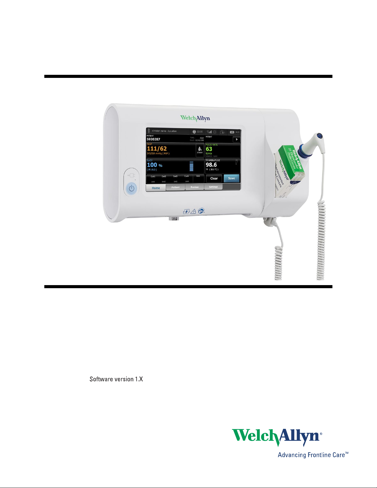
Connex
®
Spot Monitor
Directions for use
Page 2

© 2017 Welch Allyn. All rights are reserved. To support the intended use of the product described in this publication,
the purchaser of the product is permitted to copy this publication, for internal distribution only, from the media
provided by Welch Allyn. No other use, reproduction, or distribution of this publication, or any part of it, is permitted
without written permission from Welch Allyn. Welch Allyn assumes no responsibility for any injury to anyone, or for
any illegal or improper use of the product, that may result from failure to use this product in accordance with the
instructions, cautions, warnings, or statement of intended use published in this manual.
Welch Allyn, Connex, SureTemp, FlexiPort, and SureBP are registered trademarks of Welch Allyn.
EcoCuff is a trademark of Welch Allyn.
LNCS, ReSposable , SET, LNOP, and Masimo are registered trademarks of Masimo Corporation. Possession or
purchase of a Masimo SpO2-equipped device does not convey any express or implied license to use the device with
unauthorized sensors or cables which would, alone or in combination with this device, fall within the scope of one or
more of the patents relating to this device.
For Masimo patent information, please visit
www.masimo.com/patents.htm.
NellcorTM SpO2 Patient Monitoring System with OxiMaxTM Technology and NellcorTM SpO2 OxiMaxTM Technology
are registered trademarks of COVIDIEN LP Covidien Holdings Inc.
Braun and ThermoScan are registered trademarks of Braun GmbH.
Nonin is a registered trademark of Nonin Medical, Inc.
The Bluetooth® word mark and logos are registered trademarks owned by BluetoothSIG, Inc. and any use of such
marks by Welch Allyn is under license.
Software in this product is Copyright 2017 Welch Allyn or its vendors. All rights are reserved. The software is
protected by United States of America copyright laws and international treaty provisions applicable worldwide. Under
such laws, the licensee is entitled to use the copy of the software incorporated with this instrument as intended in
the operation of the product in which it is embedded. The software may not be copied, decompiled, reverseengineered, disassembled, or otherwise reduced to human-perceivable form. This is not a sale of the software or
any copy of the software; all right, title, and ownership of the software remain with Welch Allyn or its vendors.
This product may contain software known as “free” or “open source” software (FOSS). Welch Allyn uses and
supports the use of FOSS. We believe that FOSS makes our products more robust and secure, and gives us and our
customers greater flexibility. To learn more about FOSS that may be used in this product, please visit our FOSS
website at
www.welchallyn.com/opensource. Where required, a copy of FOSS source code is available on our FOSS
website.
For patent information, please visit www.welchallyn.com/patents.
For information about any Welch Allyn product, contact your local Welch Allyn representative: www.welchallyn.com/
about/company/locations.htm.
DIR 80019224 Ver. N
Revision date: 2017-04
Welch Allyn, Inc.
4341 State Street Road
Skaneateles Falls, NY 13153 USA
www.welchallyn.com
This manual applies to 901058 Vital Signs Monitor Core.
Regulatory Affairs Representative
Welch Allyn Limited
Navan Business Park
Dublin Road
Navan, County Meath
Republic of Ireland
Page 3

Contents
Introduction ............................................................................................. 1
Symbols and definitions ......................................................................... 3
About warnings and cautions ................................................................ 7
iii
Intended use ........................................................................................................ 1
Contraindications ................................................................................................. 1
General warnings and cautions ............................................................................ 7
Controls, indicators, and connectors ................................................... 13
Setup ...................................................................................................... 19
Supplies and accessories ................................................................................... 19
Connect the battery ........................................................................................... 19
Mount the monitor ............................................................................................. 20
Attach the probe well and temperature probe ................................................... 22
Remove the temperature probe and probe well ................................................ 22
Connect the NIBP hose ..................................................................................... 22
Disconnect the NIBP hose ................................................................................. 22
Connect the SpO2 cable .................................................................................... 23
Disconnect the SpO2 cable ............................................................................... 23
Attach an accessory ........................................................................................... 23
Detach an accessory .......................................................................................... 23
Disconnect AC power ........................................................................................ 23
Startup .................................................................................................... 25
Power ................................................................................................................. 25
Login methods ................................................................................................... 30
Profiles ............................................................................................................... 32
Common screen functionality ............................................................................ 36
Primary screens ................................................................................................. 37
Pop-up screens .................................................................................................. 40
Navigation .......................................................................................................... 40
Patient data management .................................................................... 43
Load patient data with the barcode scanner ...................................................... 43
Add a patient ...................................................................................................... 43
Manage patient records ..................................................................................... 44
Modifiers ............................................................................................................ 45
Patient list .......................................................................................................... 45
Page 4

iv Contents Connex® Spot Monitor
Alarms .................................................................................................... 47
Vital sign summary view .................................................................................... 47
Alarm limits ........................................................................................................ 47
Alarm reminder signal ........................................................................................ 47
Alarm types ........................................................................................................ 47
Alarm notification locations ................................................................................ 48
Icons on the Home tab ...................................................................................... 48
Reset (pause or turn off) audio alarms ............................................................... 50
Adjust vital sign alarm limits .............................................................................. 51
Modify audio alarm notification .......................................................................... 51
Alarm messages and priorities ........................................................................... 52
Nurse Call ........................................................................................................... 53
Patient monitoring ................................................................................ 55
Required parameters ......................................................................................... 55
Intervals ............................................................................................................. 56
NIBP ................................................................................................................... 59
Temperature ...................................................................................................... 63
SpO2 .................................................................................................................. 72
Modifiers and manual parameters ..................................................................... 77
Configuration tool ............................................................................................... 78
Custom scoring .................................................................................................. 78
Advanced settings ............................................................................................. 79
Maintenance and service ...................................................................... 81
Perform periodic checks .................................................................................... 81
Replace the monitor battery .............................................................................. 81
Replace the APM work surface battery ............................................................. 82
Cleaning requirements ....................................................................................... 84
Troubleshooting .................................................................................... 89
NIBP messages ................................................................................................. 89
SpO2 messages ................................................................................................. 95
Temperature messages ................................................................................... 106
Patient and clinician data messages ................................................................ 115
Radio messages ............................................................................................... 117
Connectivity messages .................................................................................... 122
System messages ........................................................................................... 123
Software update messages ............................................................................. 126
Bluetooth® messages ..................................................................................... 127
APM messages ................................................................................................ 127
Specifications ...................................................................................... 131
Physical specifications ..................................................................................... 131
Environmental specifications ........................................................................... 138
Monitor radio .................................................................................................... 138
Bluetooth® module .......................................................................................... 139
Configuration options ....................................................................................... 140
Standards and compliance ................................................................. 141
General compliance and standards .................................................................. 141
Regulatory radio compliance ............................................................................ 142
Page 5

Directions for use Contents v
Guidance and manufacturer's declaration ........................................ 147
EMC compliance .............................................................................................. 147
Emissions and immunity information ............................................................... 147
Appendices .......................................................................................... 151
Approved accessories ...................................................................................... 151
Warranty .......................................................................................................... 159
Page 6

vi Contents Connex® Spot Monitor
Page 7

Introduction
This manual describes the capabilities and operation of the Connex Spot Monitor
(monitor). The information, including the illustrations, pertains to a monitor configured
with noninvasive blood pressure (NIBP), body temperature, pulse oximetry (SpO2), and
pulse rate. If your monitor configuration lacks any of these options, some information in
this manual might not apply.
Before using the monitor, read the sections of the manual that pertain to your use of the
monitor.
1
Intended use
The Connex Spot Monitors (monitor) are intended to be used by clinicians and medically
qualified personnel for monitoring of noninvasive blood pressure, pulse rate, noninvasive
functional oxygen saturation of arteriolar hemoglobin (SpO2), and body temperature in
normal and axillary modes of neonatal, pediatric and adult patients.
The most likely locations for patients to be monitored are general medical or surgical
floors and general hospital and alternate care environments.
This product is available for sale only upon the order of a physician or licensed health
care professional.
Contraindications
This system is not intended to be used:
•
on patients connected to heart/lung machines
• on patients being transported outside a healthcare facility
• near an MRI machine
• in a hyperbaric chamber
• near flammable anesthetics
• near electro-cauterization devices
For contraindications of SpO2 sensors, consult the sensor manufacturer's directions for
use.
Page 8

2 Introduction Connex® Spot Monitor
Page 9
Symbols and definitions
Documentation symbols
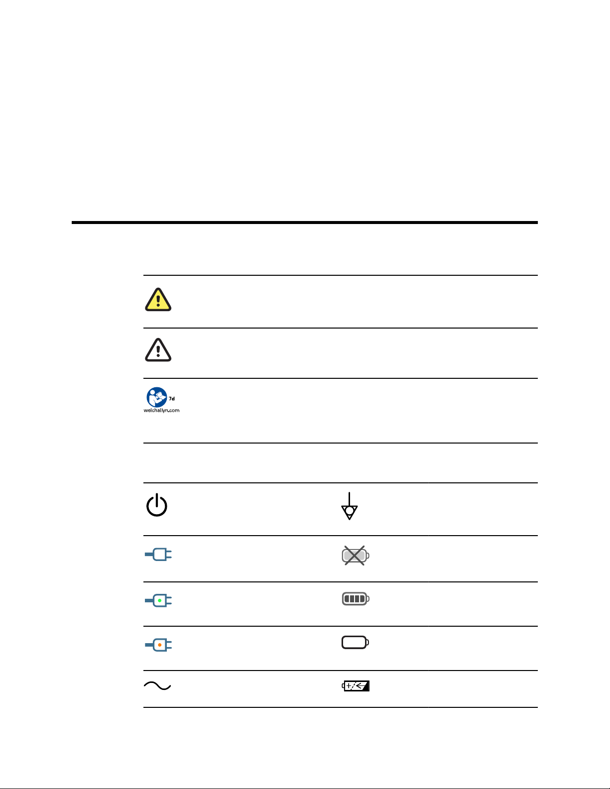
WARNING The warning statements in this manual identify conditions or practices that
could lead to illness, injury, or death. Warning statements appear with a grey background in
a black and white document.
3
Power symbols
CAUTION The caution statements in this manual identify conditions or practices that could
result in damage to the equipment or other property, or loss of data. This definition applies
to both yellow and black and white symbols.
Follow instructions/directions for use (DFU) -- mandatory action.
A copy of the DFU is available on this website.
A printed copy of the DFU can be ordered from Welch Allyn for delivery within 7 calendar
days.
Stand-By
Power plug Battery absent or faulty
Alternating Current power
present, battery fully charged
Equipotential Ground
Battery charge level
Alternating Current power
present, battery is charging
Alternating current (AC) Rechargeable battery
Battery
Page 10
4 Symbols and definitions Connex® Spot Monitor
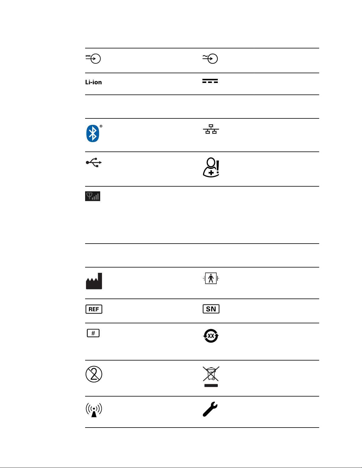
Rated power input, DC Rated power input, AC
Lithium-ion battery Direct current (DC)
Connectivity symbols
Bluetooth
USB Nurse call
Wireless signal strength
• Best (4 bars)
• Good (3 bars)
• Fair (2 bars)
• Weak (1 bar)
• No signal (no bars)
• No connection (blank)
Miscellaneous symbols
Manufacturer
®
Ethernet
Defibrillation-proof Type BF
applied parts
Product Identifier Serial Number
Reorder Number China RoHS markings for control
of pollution caused by electronic
information products. XX
indicates Environmentally
Friendly Use Period in years.
Do not reuse, Single use device Separate collection of Electrical
and Electronic Equipment. Do not
dispose as unsorted municipal
waste.
Non-ionizing electromagnetic
radiation
Call for maintenance
Page 11
Directions for use Symbols and definitions 5
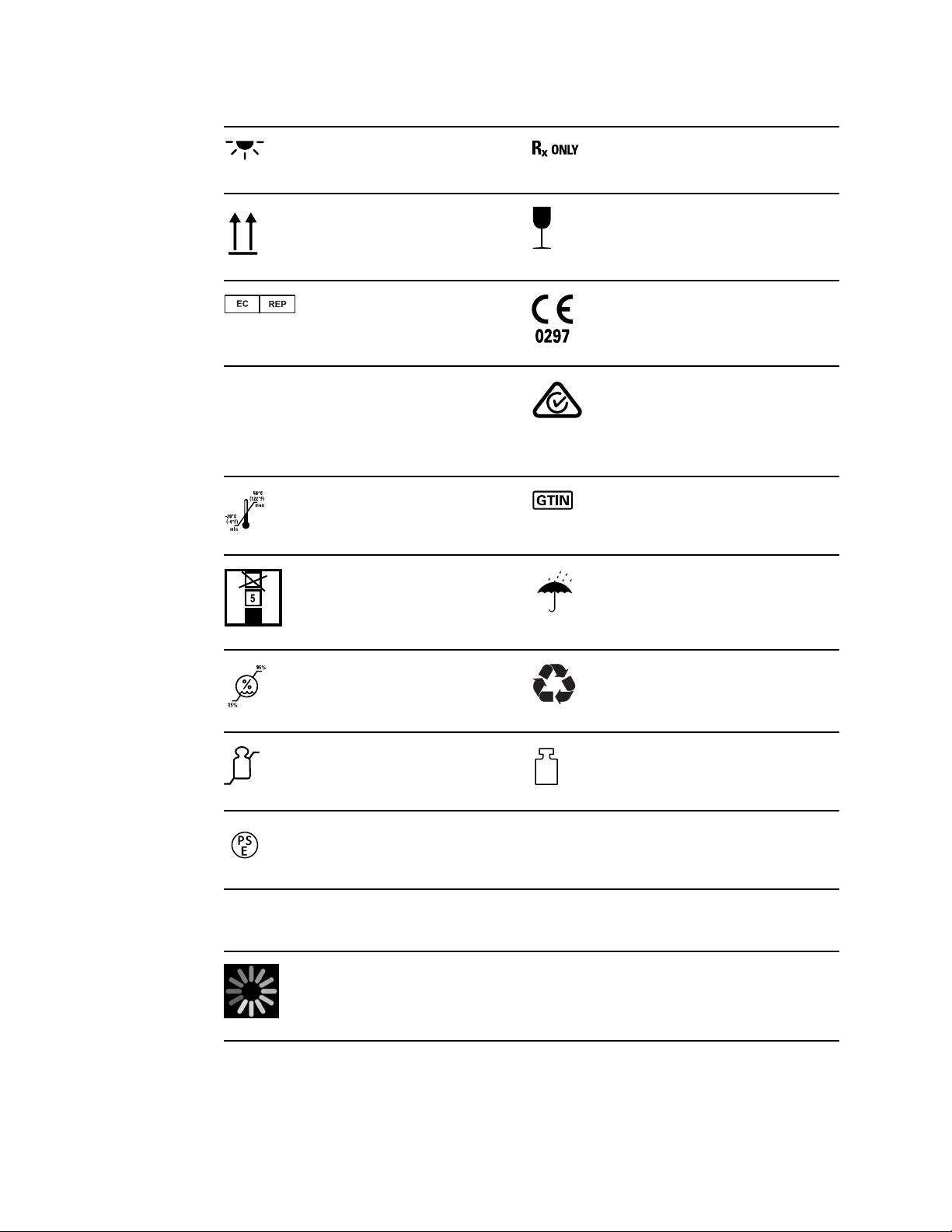
Task Light Prescription only or "For Use by or
on the order of a licensed
medical professional"
This way up Fragile
Authorized Representative in the
European Community
IPX1 IP = International Protection
Marking
X = No object ingress rating
1 = Protected against vertically
dripping water
Temperature limit Global Trade Item Number
Stacking limit by number Keep dry
Humidity limitation Recyclable
Meets essential requirements of
European Medical Device
Directive 93/42/EEC
Australian Communications and
Media Authority (ACMA) Radio
Compliance Mark (RCM).
Screen symbol
Maximum safe working load
limits
Japan's PSE approval symbol for
Category A
Process indicator for activities like acquiring measurements and
connecting to a laptop
Mass in kilograms (kg)
Page 12

6 Symbols and definitions Connex® Spot Monitor
Page 13

About warnings and cautions
Warning and caution statements can appear on the monitor, on the packaging, on the
shipping container, or in this document.
The monitor is safe for patients and clinicians when used in accordance with the
instructions and the warning and caution statements presented in this manual.
Before using the monitor, familiarize yourself with the sections of this directions for use
that pertain to your use of the monitor.
7
WARNING The warning statements in this manual identify conditions or
practices that could lead to illness, injury, or death.
CAUTION The caution statements in this manual identify conditions or
practices that could result in damage to the equipment or other property, or
loss of patient data.
General warnings and cautions
WARNING Patient injury risk. Many environmental variables, including
patient physiology and clinical application, can affect the accuracy and
performance of the monitor. Therefore, you must verify all vital signs
information, especially NIBP and SpO2, before treating the patient. If there
is any question about the accuracy of a measurement, verify the
measurement using another clinically accepted method.
WARNING Patient injury risk. To ensure data integrity and patient
confidentiality, save readings and clear the monitor's display between
patients.
WARNING Personal injury risk. The power cord is the disconnect device to
isolate this equipment from supply mains. Position the equipment so that it
is not difficult to reach or disconnect the cord.
WARNING Patient injury risk. Damaged cords, cables, and accessories can
affect patient and operator safety. Never lift the monitor by the power
supply cord or patient connections. Routinely inspect the AC power cord,
blood pressure cuff, SpO2 cable, and other accessories for strain relief
wear, fraying, or other damage. Replace as necessary.
WARNING Patient injury risk. During defibrillation, keep discharge paddles
away from monitor sensors and other conductive parts in contact with the
patient.
Page 14

8 About warnings and cautions Connex® Spot Monitor
WARNING Patient injury risk. Any external compression of the blood
pressure hose or cuff may cause patient injury, system errors, or inaccurate
measurements.
WARNING Patient injury risk. Wash hands to reduce the risk of crosscontamination and nosocomial infection.
WARNING Patient injury risk. Do not place the monitor in any position that
might cause it to fall on the patient.
WARNING Patient injury risk. Verify patient identity on the monitor after
manual or barcode entry and before printing or transferring patient records.
Failure to identify the correct patient can result in patient injury.
WARNING Patient injury risk. If you use Stat mode repeatedly, periodically
observe the patient's limb to ensure that circulation is not impaired and that
the cuff remains in place. Prolonged impairment of circulation or improper
cuff position can cause bruising.
WARNING Patient injury risk. Do not place the cuff on the arm on the
same side of a mastectomy. If necessary, use the femoral artery in the
thigh to take a measurement.
WARNING Inaccurate measurement risk. Do not place the cuff where it
can disturb proper circulation. Do not place the cuff on any area where
circulation is compromised or on any extremity used for intravenous
infusions. Do not use an SpO2 finger clip sensor and a blood pressure cuff
simultaneously on the same limb. Doing so may cause a temporary loss of
pulsatile flow, resulting in either no reading or an inaccurate SpO2 or pulse
rate until the flow returns.
WARNING Do not apply cuff to areas on patient where skin is delicate or
damaged. Check cuff site frequently for irritation.
WARNING Equipment failure and patient injury risk. Do not cover the air
intake or exhaust vents on the rear and base of the monitor. Covering
these vents could cause overheating of the monitor or muffling of alarms.
WARNING This equipment is not suitable for use in the presence of
electro-surgery.
WARNING For operator and patient safety, peripheral equipment and
accessories that can come in direct patient contact must comply with all
applicable safety, EMC, and regulatory requirements.
WARNING Equipment damage and personal injury risk. When transporting
the monitor on a mobile stand, properly secure all patient cables and cords
to keep them clear of the wheels and to minimize trip hazards.
WARNING Equipment damage and personal injury risk. No modifications
to the monitor are allowed by anyone other than a qualified Welch Allyn
service representative. Modification of the monitor could be hazardous to
patients and personnel.
WARNING Fire and explosion hazard. Do not operate the monitor in the
presence of a flammable anesthetic mixture with air, oxygen, or nitrous
oxide; in oxygen-enriched environments; or in any other potentially
explosive environment.
Page 15

Directions for use About warnings and cautions 9
WARNING Fire and shock hazard. Only connect LAN cables contained
within the perimeter of a single building. Conductive LAN cables spanning
multiple buildings may introduce fire or shock hazards unless they are fitted
with fiber optic cables, lightning arresters, or other applicable safety
features.
WARNING Electric shock hazard. This equipment must only be connected
to a supply mains with protective earth.
WARNING Electric shock hazard. Do not open the monitor or attempt
repairs. The monitor has no user-serviceable internal parts. Only perform
routine cleaning and maintenance procedures specifically described in this
manual. Inspection and servicing of internal parts shall only be performed
by qualified service personnel.
WARNING Electric shock hazard. All signal input and output (I/O)
connectors are intended for connection of only devices complying with IEC
60601-1, or other IEC standards (for example, IEC 60950), as applicable to
the monitor. Connecting additional devices to the monitor may increase
chassis or patient leakage currents. To maintain operator and patient
safety, consider the requirements of IEC 60601-1-1. Measure the leakage
currents to confirm that no electric shock hazard exists.
WARNING Explosion or contamination hazard. Improper disposal of
batteries may create an explosion or contamination hazard. Never dispose
of batteries in refuse containers. Always recycle batteries according to local
regulations.
WARNING Use the monitor only as described in this directions for use. Do
not use the monitor on patients as described in the Contraindications.
WARNING Alarm limits are patient- or facility-specific. The clinician must
set or verify alarm limits appropriate for each patient. Each time the
monitor is powered on, you must check that the alarm settings are
appropriate for your patient before you start monitoring.
WARNING Inaccurate measurement risk. The monitor is not intended for
use during patient transport outside of the medical facility. Do not use the
monitor to take measurements on any patient in transit.
WARNING Inaccurate measurement risk. Do not connect more than one
patient to a monitor.
WARNING Inaccurate measurement risk. Dust and particle ingress can
affect the accuracy of blood pressure measurements. Use the monitor in
clean environments to ensure measurement accuracy. If you notice dust or
lint build-up on the monitor's vent openings, have the monitor inspected
and cleaned by a qualified service technician.
WARNING Inaccurate measurement risk. Do not expose to temperatures
higher than 122º F (50º C).
WARNING Inaccurate measurement risk. Do not use the monitor on
patients who are on heart-lung machines.
WARNING Inaccurate measurement risk. Do not use the monitor on
patients who are experiencing convulsions or tremors.
Page 16

10 About warnings and cautions Connex® Spot Monitor
WARNING Liquids can damage electronics inside the monitor. Prevent
liquids from spilling on the monitor.
If liquids are spilled on the monitor:
1. Power down the monitor.
2. Disconnect the power plug.
3. Remove battery pack from the monitor.
4. Dry off excess liquid from the monitor.
Note If liquids possibly entered the monitor, remove the monitor
from use until it has been properly dried, inspected, and
tested by qualified service personnel.
5. Reinstall battery pack.
6. Reconnect the power plug.
7. Power on the monitor and verify that the monitor functions normally before
using it.
WARNING The monitor may not function properly if dropped or damaged.
Protect it from severe impact and shock. Do not use the monitor if you
notice any signs of damage. Qualified service personnel must check any
monitor that is dropped or damaged for proper operation before putting the
monitor back into use.
WARNING Defective batteries can damage the monitor. If the battery
shows any signs of damage or cracking, it must be replaced immediately
and only with a battery approved by Welch Allyn.
WARNING Personal injury risk. Improper handling of the battery can lead
to heat generation, smoke, explosion or fire. Do not short-circuit, crush,
incinerate, or disassemble the battery. Never dispose of batteries in refuse
containers. Always recycle batteries according to national or local
regulations.
WARNING Use only Welch Allyn approved accessories, and use them
according to the manufacturer’s directions for use. Using unapproved
accessories with the monitor can affect patient and operator safety and can
compromise product performance and accuracy, and void the product
warranty.
WARNING Wall mounted equipment and accessories must be installed in
accordance with accompanying instructions. Welch Allyn is not responsible
for the integrity of any installation not performed by authorized Welch Allyn
service personnel. Contact an authorized Welch Allyn service
representative or other qualified service personnel to ensure professional
installation for safety and reliability of any mounting accessory.
WARNING Welch Allyn is not responsible for the integrity of a facility's
power. If the integrity of a facility's power or protective earth conductor is
in doubt, always operate the monitor on battery power alone when it is
attached to a patient.
CAUTION Electric shock hazard. Do not sterilize the monitor. Sterilizing
the monitor could damage the device.
Page 17

Directions for use About warnings and cautions 11
CAUTION United States Federal law restricts this monitor to sale,
distribution, or use by or on the order of a physician or licensed healthcare
professional.
CAUTION Electromagnetic interference risk. The monitor complies with
applicable domestic and international standards for electromagnetic
interference. These standards are intended to minimize medical equipment
electromagnetic interference. Although this monitor is not expected to
present problems to other compliant equipment or be affected by other
compliant devices, interference issues still may occur. As a precaution,
avoid using the monitor in close proximity to other equipment. In the event
that equipment interference is observed, relocate the equipment as
necessary or consult manufacturer's directions for use.
CAUTION Do not move the stand while the power source is plugged into
the mains outlet.
CAUTION Do not sterilize the monitor. Sterilizing the monitor could harm
the device.
CAUTION Use only a Class I (grounded) AC power cord to charge the
power source for the monitor.
CAUTION Do not use a long press of to power down the monitor when
it is functioning normally. You will lose patient data and configuration
settings.
CAUTION Never move the monitor or mobile stand by pulling on any of
the cords. This may cause the monitor to tip over or damage the cord.
Never pull on the power cord when disconnecting the cord from the mains
outlet. When disconnecting the power cord, always grasp the attachment
plug. Keep the cord away from liquids, heat, and sharp edges. Replace the
power cord if the strain relief, cord insulation, or metal prongs are damaged
or begin to separate from the attachment plug.
CAUTION Use only the Welch Allyn USB client cable to connect a laptop
computer to the USB client port. Any laptop connected to the monitor must
be running on a battery, a 60601-1 compliant power supply, or a 60601-1
compliant isolation transformer.
CAUTION If the touchscreen is not responding properly, refer to the
troubleshooting section. If the problem cannot be resolved, discontinue use
of the monitor and contact an authorized Welch Allyn service center or
qualified service personnel.
Page 18

12 About warnings and cautions Connex® Spot Monitor
Page 19
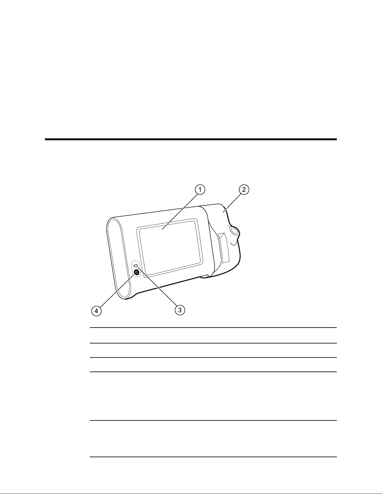
Controls, indicators, and connectors
Note Your model might not contain all of these features.
Front-Left view
13
No. Feature Description
1 LCD screen 7" color touchscreen provides a graphical user interface.
2 Thermometry Secures the SureTemp unit to the monitor
3 Battery charge and power-up status indicator
4 Power button
The LED indicates the charging and power-up status when
connected to AC power:
• Green: The battery is charged.
• Amber: The battery is charging.
• Flashing: the monitor is powering up.
Blue button on lower-left corner of the monitor.
• Powers on the monitor
• Places the monitor into Sleep mode, except when an alarm
condition is active (brief press)
Page 20

14 Controls, indicators, and connectors Connex® Spot Monitor
No. Feature Description
• Wakes up the monitor from Sleep mode
Page 21
1
4
3
2
6
7
5
8
9
Directions for use Controls, indicators, and connectors 15
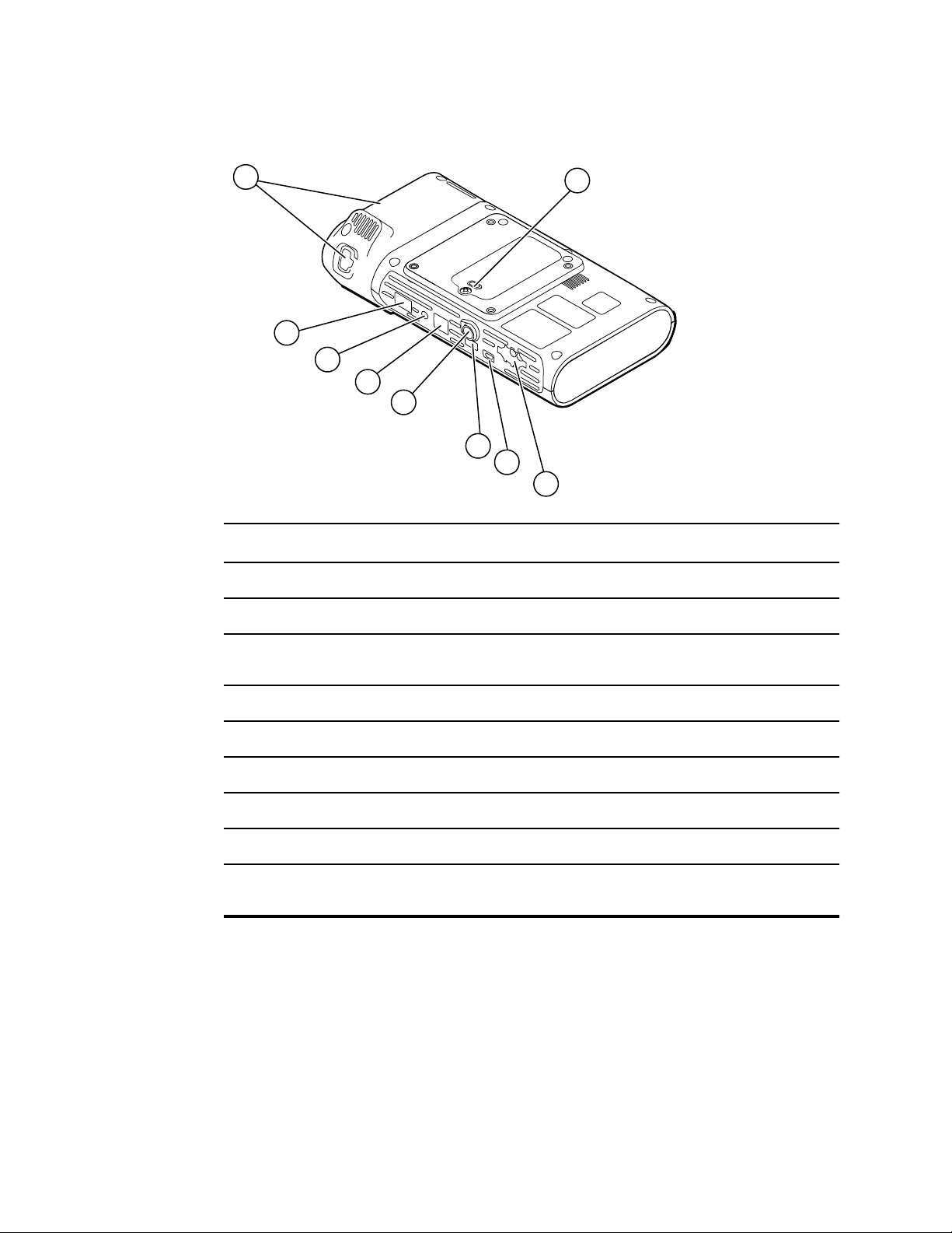
Back-Bottom-Left view
No. Feature Description
1 Battery compartment (behind cover) Houses the battery (captive screw secures cover to monitor)
2 NIBP Connects NIBP cable to monitor
3 USB client port Provides a connection to an external computer for testing and
software upgrades
4 USB port Connects APM work surface to monitor
5 Power connection Connects APM work surface or any accessory to the monitor
6 Ethernet RJ-45 Provides a hardwired connection to the computer network
7 Nurse call Provides a connection to a hospital nurse call system
8 SpO2 Connects chosen SpO2 system to monitor
9 Thermometry Configuration shown features SureTemp module and probe
connection port
Page 22
3
1
2
16 Controls, indicators, and connectors Connex® Spot Monitor
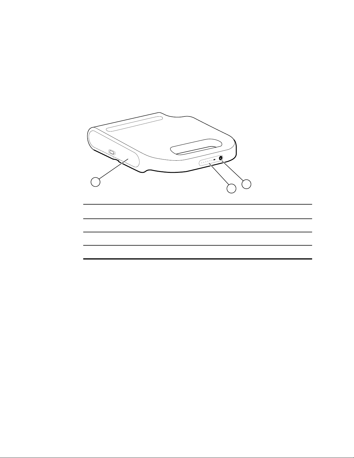
APM
This section applies only to devices with an Accessory Power Management (APM) stand.
The APM is an accessory stand with work surface, power supply for enhanced device
run time, and organizational bins to arrange sensors and cables for available parameters.
Front-Top-Left view
No. Feature Description
1 Battery compartment (behind cover) Houses the battery
2 Battery charge status indicator Indicates charge level of battery
3 Light power switch Powers light under APM work surface
Page 23

6
7
4
1 2
5
9
8
3
Directions for use Controls, indicators, and connectors 17
Back-Bottom-Right view
No. Feature Description
1 Printer port Connect a printer (future use)
2 USB ports (2) Connect optional accessories
3 USB cable Connects APM work surface to monitor
4 APM power cable Connects APM work surface to monitor
5 Power connection Provides an external AC power connection
6 Ground lug (equipotential terminal) Provided for electrical safety testing and for connecting a
potential-equalization conductor
7 Recess for mounting Secures the APM work surface when it is mounted on the APM
stand (with 4 screws)
8 Battery cover screw Secures APM work surface battery cover
9 APM light Illuminates accessory bins and path for APM stand
Page 24

18 Controls, indicators, and connectors Connex® Spot Monitor
Page 25

Setup
Supplies and accessories
19
For a list of all approved supplies and accessories, see
Appendices.
WARNING Patient injury risk. Clean all accessories, including cables and
tubes, before storing the accessories on the device or cart. This helps
reduce the risk of cross contamination and nosocomial infection. Refer to
'Clean the equipment' in "Maintenance and service" for directions.
Connect the battery
This procedure applies to first-time setup of the monitor. The battery is inserted in the
battery compartment when you receive a new monitor. However, it is not connected.
WARNING Personal injury risk. Improper handling of the battery can lead
to heat generation, smoke, explosion, or fire. Do not short-circuit, crush,
incinerate, or disassemble the battery. Never dispose of batteries in refuse
containers. Always recycle batteries according to national or local
regulations.
WARNING Use only Welch Allyn approved accessories, and use them
according to the manufacturer’s directions for use. Using unapproved
accessories with the monitor can affect patient and operator safety and can
compromise product performance and accuracy, and void the product
warranty.
Approved Accessories in the
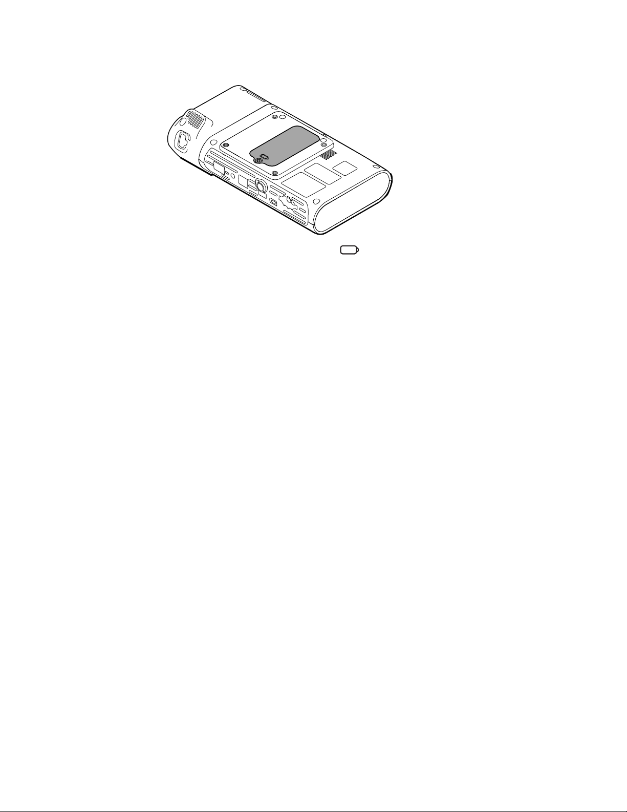
1. Set the monitor on a flat surface with the screen facing downward to access the
battery cover.
Page 26
20 Setup Connex® Spot Monitor
2. Locate the battery cover, indicated by on the back of the monitor.
3. Using a double-slotted screwdriver, loosen the captive screw at the base of the
battery cover, and then remove the cover.
4. Remove the battery to access the battery connection port on the monitor.
5. Insert the battery connector into the battery connection port on the monitor.
6. Insert the battery into the battery compartment.
7. Replace the battery cover, and then tighten the captive screw at the bottom of the
battery cover.
Note Do not over-tighten the screw.
Mount the monitor
The Connex Spot Monitor can be mounted on either the MS3 Connex Spot Classic
Mobile Stand, Accessory Power Management (APM) stand, or wall mount. When
mounted on an MS3 stand, a separate power supply is required. This power supply
connects directly to the mains outlet. Follow the assembly instructions or directions
for use included with your stand or wall mount. If you have an APM stand, follow all
instructions regarding the equipotential terminal.
Connect AC power to a power source
You can use the monitor with power from the mains outlet. Battery power can be used
after charging the battery.
Refer to the AC power directions in the
stand to which you are mounting your monitor.
Connect AC power to APM and monitor
To connect the monitor to the APM stand, refer to the APM Assembly instructions.
Instructions for use that accompanied the
Page 27

Directions for use Setup 21
Connect AC power to MS3 Classic stand and monitor
This section applies only to devices with Classic (MS3) stands.
1. Thread the power cable from the power supply through one of the spaces next to
the pole to reach the monitor.
2. Attach the power supply to the underside of the basket using the 2 Phillips screws
provided.
3. Connect the power cable to the monitor.
4. Connect the power cord to the mains outlet.
5. Power up the monitor.
Page 28
22 Setup Connex® Spot Monitor
Attach the probe well and temperature probe
1. Align the slots on the monitor and probe well, and slide the probe well onto the
monitor.
The probe well snaps into place when it is fully seated.
2. Attach the SureTemp probe connector to the bottom of the monitor.
3. Insert the SureTemp probe into the probe well.
4. In the compartment to the left of the probe well, insert a Welch Allyn probe cover
carton.
Additional cartons of probe covers can be stored in the lower compartments of the
cart if a cart is used.
Remove the temperature probe and probe well
Follow these steps to disconnect the probe cable and remove the probe well.
1.
Press the spring tab on the SureTemp probe connector and pull it out of the
connection port. The probe connector port is located on the bottom of the monitor.
2. Remove the SureTemp probe from the probe well.
3. Grasp the probe well and pull it up to remove it from the monitor.
Connect the NIBP hose
1. Place your thumb and forefinger on the hose connector spring tabs and squeeze
firmly.
2. Align the hose connector with the hose connector port on the bottom of the monitor.
3. Insert the hose connector, pressing firmly until both of the spring tabs click into
place.
Disconnect the NIBP hose
1. Place your thumb and forefinger on the hose connector spring tabs.
Page 29

Directions for use Setup 23
Note Always grasp the hose by the connector spring tabs. Do not
pull on the hose itself.
2. Squeeze and pull the spring tabs until the connector releases.
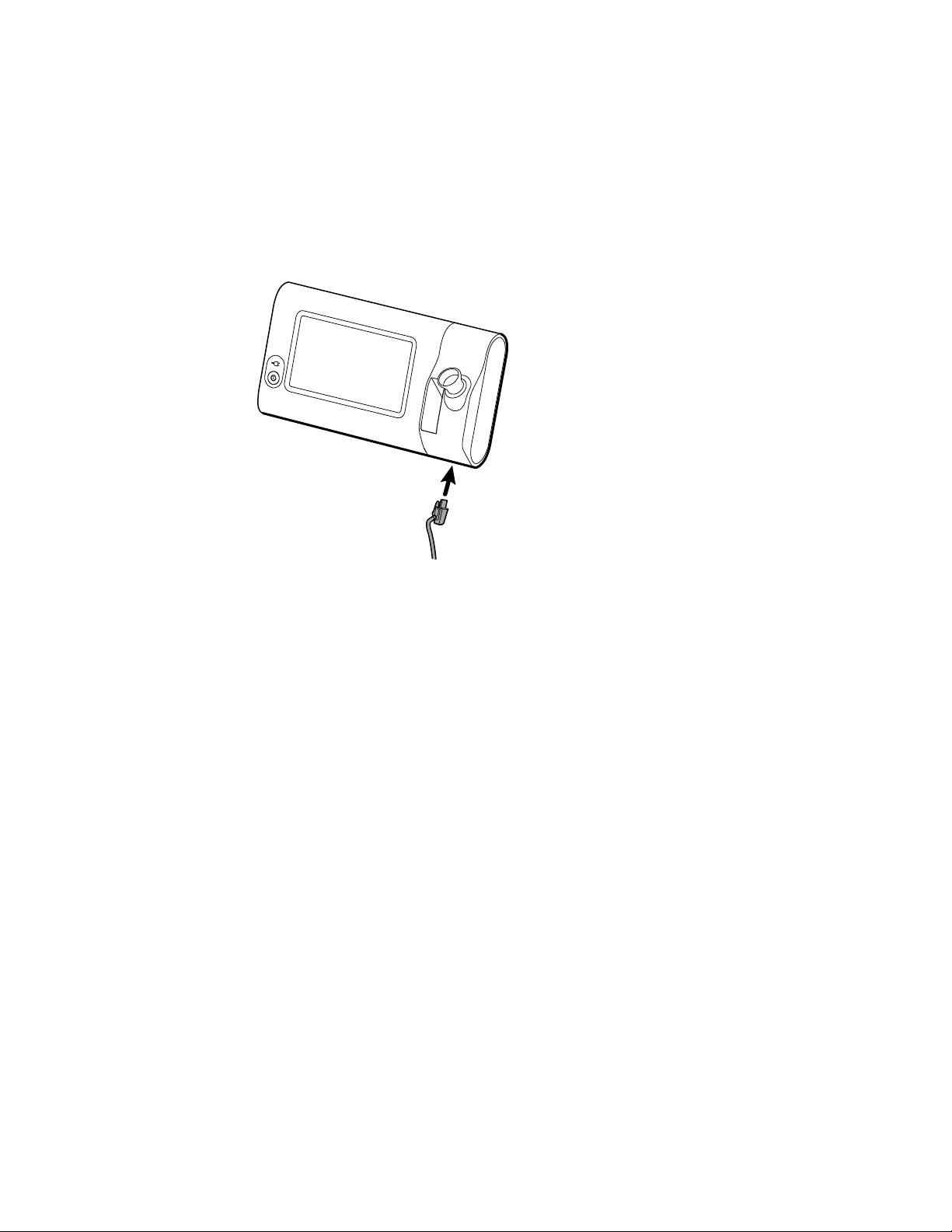
Connect the SpO2 cable
WARNING Patient injury risk. Do not use a damaged sensor or pulse
oximetry cable or a sensor with exposed electrical or optical components.
1. On the bottom of the monitor, align the SpO2 cable connector with the cable
connector port.
2. Insert the cable connector, pressing firmly until the connector is seated.
Disconnect the SpO2 cable
1. Place your thumb and forefinger on the Sp02 cable connector. Do not grasp the
cable.
2. Pull the Sp02 cable connector out of the connector port.
Attach an accessory
CAUTION Accessories attached to this monitor must run on battery
power. Do not use any accessory's external power supply when it is
attached to the monitor.
To attach an accessory to the monitor, follow the Directions for use that
accompanied the accessory.
CAUTION Connect cables in a manner that minimizes
entangling.
Detach an accessory
To detach an accessory from the monitor, follow the instructions that accompanied
the accessory.
Disconnect AC power
CAUTION Never move the monitor or mobile stand by pulling on any of
the cords. This may cause the monitor to tip over or damage the cord.
Never pull on the power cord when disconnecting the cord from the mains
outlet. When disconnecting the power cord, always grasp the attachment
plug. Keep the cord away from liquids, heat, and sharp edges. Replace the
power cord if the strain relief, cord insulation, or metal prongs are damaged
or begin to separate from the attachment plug.
1. Grasp the power line cord.
2. Pull the power line cord from the mains outlet.
Page 30

24 Setup Connex® Spot Monitor
Page 31

Startup
Power
25
The Power button, located on the lower-left corner of the monitor, performs multiple
functions.
• Powers up the monitor
• Wakes the monitor from Sleep mode
• Opens a pop-up dialog with controls to sign out, power down, and enter Sleep mode
(except when an alarm condition is active)
The LED in the center of the power plug symbol indicates the battery charging status.
•
Green indicates that AC power is present and that the battery is fully charged.
• Amber indicates that AC power is present and that the battery is charging.
Power up the monitor
The monitor runs a brief diagnostic self-test each time it powers up. If an alarm situation
occurs, the alert appears in the Status area.
Type of alert Color
CAUTION Do not use a long press of the Power button to power down
the monitor when it is functioning normally. You will lose patient data and
configuration settings. Touch the Settings > Device tabs to power down
the monitor.
WARNING To ensure patient safety, listen for two audible indicators (a
beeper and a speaker tone) and watch for visual alerts at power-up at least
once daily. Correct any system errors before using the monitor. In addition
to the audible indicators, the screen Status area displays color coding,
icons, and messages that help you to distinguish clinical priority and
actions, if needed.
High Alarm
Medium Alarm
Red
Flashing amber
Page 32

26
Startup Connex® Spot Monitor
Type of alert Color
Low Alarm
Very Low Alarm
Information message
WARNING Steady amber indicates a low-level alarm. Flashing amber
indicates a medium-level alarm. Flashing red indicates a high-level alarm.
WARNING Always observe the monitor during power-up. If any display
fails to illuminate properly, or if a system fault code or message displays,
inform qualified service personnel immediately, or call your nearest Welch
Allyn Customer Service or Technical Support facility. Do not use the
monitor until the problem is corrected.
CAUTION Always use the monitor with an adequately charged and
properly functioning battery.
CAUTION During intervals monitoring, keep the monitor connected to AC
power at all times.
CAUTION Use only a Class I (grounded) AC power cord to charge the
battery for this monitor.
Steady amber
Cyan
Blue
Press to power up the monitor.
When the device is powering up, the LED flashes until the monitor displays the
Welch Allyn logo and a power-up tone sounds.
A pop-up screen appears, depending on your configuration and functionality.
•
On initial power-up, the monitor prompts you to set the language, date, and time.
See “Change the language” and “Set the date and time” for directions.
• If your facility has chosen a login format, then the first image you see is the login
screen.
• If your facility has not chosen a login format, then the first image you see is the
Home tab.
•
If Bluetooth® is enabled, a list of paired devices and the option to add a new device
is available.
Bluetooth® wireless technology
Note Your model might not contain all of these features.
Bluetooth wireless technology is available in the Office profile.
Page 33

Directions for use Startup 27
Bluetooth status
A monitor with Bluetooth wireless technology displays the status between the monitor
and the laptop in the Status area.
Image Description
No image Bluetooth radio is OFF
Bluetooth icon appears in Status area Bluetooth radio is ON
Bluetooth icon is blinking on / off slowly The monitor is pairing with the laptop
Bluetooth icon is blinking on / off quickly The monitor is connecting with the laptop
Bluetooth icon appears with a border around the icon in
the Status area
In order to transmit data, you must first pair and then connect the monitor and the
laptop.
Pair devices with Bluetooth wireless technology
When a monitor with Bluetooth wireless technology powers on and there are laptops
already paired with the monitor, a pop-up screen appears showing the laptops available
for connection with the monitor. Follow the directions below to pair an additional device
with the monitor.
1.
Touch .
2. Touch Add new device.
3. In your Bluetooth program manager on your laptop task bar, select the monitor from
the list of available devices.
A message appears indicating that the monitor has been discovered and displays a
confirmation number on both the laptop and monitor screens.
4. Confirm that the numbers match on the laptop and on the monitor, and then touch
Accept.
A message appears indicating that the monitor and laptop are paired.
5. Touch OK.
The monitor and the laptop are connected and the
monitor is ready to transmit data
A screen appears that allows you to change the laptop name to a preferred name.
6. Enter the preferred name, and then touch Save.
The new name appears in the list of paired devices.
Connect devices with Bluetooth wireless technology and download data
In the Bluetooth connection screen, select a laptop from the list of paired devices.
1.
The Bluetooth icon in the Device Status area quickly blinks on and off as the monitor
and laptop are connecting.
When the monitor and the laptop connect, an information message briefly appears
that names the connected laptop. When the message disappears, the name of the
connected laptop appears on the top left of the screen, and the Bluetooth connected
icon appears in the connection area.
Page 34

28 Startup Connex® Spot Monitor
2. As the laptop downloads data, the progress indicator spins in the connection area.
The Bluetooth connection remains active until the download is complete. After a
successful download, the system clears data from the monitor and disconnects the
monitor from the laptop.
3. Repeat the process as needed, or touch Cancel to dismiss the Bluetooth connection
screen.
Rename a laptop
You can rename a paired laptop from a system or generic name to a specific name.
1. Select the arrow button to the right of the laptop name you want to edit in the paired
list.
A screen appears that allows you to change the laptop name to a preferred name.
2. Enter the name, and then touch Save.
The new name appears in the list of paired devices.
Set the date and time
Depending on your facility's configuration, the date and time may already be set. If the
time is set in the network configuration, the network time overrides any manual time
that is set.
1.
Touch the Settings tab.
2. Touch the Date / Time vertical tab.
3. Touch either the ▲ or ▼ keys or the the key pad, set the date and time.
Note The date and time stamps on saved patient measurements
Change the language
Refer to “Advanced Settings” in the Service manual for instructions on how to change
the language.
Power down the monitor
If you power down the monitor using the button, patient measurements are retained
in the monitor memory for a maximum of 24 hours. These saved measurements are
available for recall or electronic transmission to the network. This method also ensures
that any configuration settings you have changed and saved will be maintained at the
next startup.
Press .
1.
If there is a software update available, then a system message asks if you want to
upgrade the software.
2. If you want to upgrade the software, touch OK.
will adjust when you change the date and time settings.
3. If there is no system message, a dialog box appears with options.
• Sign out (if you signed in with a Clinician ID)
• Power down
Page 35

Directions for use Startup 29
• Sleep
• Cancel
4. Touch one of the options.
The monitor will either sign you out as a clinician so that another clinician can sign in,
power down, go into Sleep mode, or return to the prior screen, depending on the
option you choose. The battery continues to charge when in Sleep mode.
Reset the monitor
1. If the monitor stops functioning, press and hold , located on the lower-left corner
of the monitor, to reset the monitor.
2. If there is a prompt with options to power down, Sleep, or Cancel, continue to press
.
The monitor performs a power reset.
CAUTION Do not use a long press of to power down the monitor when
it is functioning normally. You will lose patient data and configuration
settings. See “Power down the monitor” to power down the monitor.
Sleep mode
After a configurable amount of time, the monitor enters sleep mode. Different types of
inactivity have different time delays.
•
When a configurable amount of time has passed since the last screen press
• The sensor modules are not being used to capture vitals
• If the monitor does not have an active alarm
The monitor does not enter sleep mode when it is in Intervals monitoring.
Three situations cause the monitor to leave sleep mode.
•
The power button is pressed.
• The screen is tapped.
• An alarm occurs.
Enter Sleep mode
1. Press .
2. If there is no system message, a dialog box appears with options.
• Sign out (if you signed in with a Clinician ID)
• Power down
• Sleep
• Cancel
3. Touch Sleep.
The monitor enters Sleep mode.
Page 36

30 Startup Connex® Spot Monitor
Exit Sleep mode
1. Press either or tap the screen.
The Login dialog box appears.
2. If you are the current user and are in a facility-specific login format, use the scanner
or keypad to enter your ID and password.
If you are logging back into the monitor, the monitor returns to the screen that
previously was visible, keeps the patient's context, and maintains the vital signs that
could have been previously captured.
3. If you are a new user, use the barcode scanner or keypad to enter your ID and
password.
Login methods
You can sign in to the monitor in two ways:
• By signing in on the login screen if your facility has chosen a login format.
• By signing in on the Clinician tab if your facility has not chosen a login format.
Sign in using the login screen
1. Using the keyboard or the barcode scanner, enter your ID and password in the
respective fields, and then touch Sign in.
The Profile selection area becomes active and contains from one to three profiles.
2. From the profiles displayed for your level of permissions, select the desired profile.
The Home tab for the chosen profile appears.
Sign in using the Clinician tab
1. Touch the Settings > Clinician tabs.
2. Using the keyboard or the barcode scanner, enter your ID and password in the
respective fields, and then touch Sign in.
Page 37

Directions for use Startup 31
The Clinician ID appears in the Clinician ID field on this tab and in the Status area on
the Home tab.
Use a barcode scanner
The monitor enables the scanning of patient and clinician barcodes to enter ID
information. The barcode scanner (scanner) supports linear and two-dimensional
barcodes.
If you have not done so previously, use the instructions provided with the scanner to
attach the scanner to the monitor.
Note Refer to the manufacturer's instructions to ensure that the scanner is set
to USB Com Emulation mode. Confirm the type of EMR version being used
by your facility.
1. Remove the scanner from its holder.
2. Hold the scanner approximately 6 inches (15.4 cm) from the barcode and squeeze
the scanner trigger so that the light from the scanner appears on the barcode.
Once the scanner completes a successful barcode reading, the ID appears in the
targeted area (Patient frame, data field, or Device Status area). See the additional
notes below.
If the scanner has difficulty reading the barcode, slowly adjust the distance and the
angle between the scanner and the barcode while squeezing the scanner trigger. If it
continues to have difficulty, verify that the barcode is as flat as possible.
Note You can scan a patient's barcode from the Home tab. The scanned ID
appears in the Patient frame on the Home tab.
Note Scanning a clinician ID while the Clinician ID pane is open places the
scanned ID into the Clinician ID section of the Device Status area. Touch
OK to return to the Home tab and to begin obtaining patient
measurements.
Page 38

32 Startup Connex® Spot Monitor
Profiles
The monitor offers multiple profiles, including Spot, Office, and Intervals.
Note Your model might not contain all of these features.
Spot profile
The Spot profile is optimized for rapid multi-patient vitals capture with custom and
additional parameters, facility-specific login format, vital sign capture, and multiple
patient review.
The Spot profile Home tab displays the following parameters and features:
• NIBP
• Pulse rate
• Respiration rate
• Temperature
• SpO2
• Custom scores
• Additional parameters
• WiFi and ethernet capability
Configurable parameters can be accessed in the Spot profile on the Home tab by
touching the relative parameter.
Office profile
The Office profile is optimized for ambulatory vitals capture with external patient context
and optional Bluetooth® functionality.
The Office profile Home tab displays the following parameters and features:
NIBP
•
• Pulse rate
Page 39

Directions for use
• Temperature
• SpO2
• BMI
• Height, weight, pain
•
USB and Bluetooth® capability
Startup 33
Intervals profile
The Intervals profile is optimized for unattended episodic interval monitoring of a single
patient with single patient review and alarms.
The Intervals profile Home tab displays the following parameters and features:
•
NIBP
• Pulse rate
• Respiration rate
• Temperature
• SpO2
• Alarms
• Custom scores
• Additional parameters
• WiFi and ethernet capability
Configurable parameters can be accessed in the Intervals profile on the Home tab by
touching the relative parameter.
Page 40

34 Startup Connex® Spot Monitor
Page 41

Directions for use Startup 35
Profile feature comparison
The monitor offers multiple profiles, including Spot, Office, and Interval.
Note Your model might not contain all of these features.
Profile feature comparison
The following table compares the features of the profiles.
Feature Spot Office Intervals
Configure and use interval
timing setting
Observe and configure alarm
limits
Observe and respond to
physiological alarms
Access Alarms tab X
Take NIBP, SpO2,
temperature, and pulse rate
readings
Change patient type (adult,
pediatric, neonate)
View and enter manual
parameters (height, weight,
pain, respiration,
temperature and BMI)
Save currently displayed data
to device memory
Save patient data X X X
X X X
X X X
X X X
1
X X X
X
X
X
Review patient data X X X
Access Patients tab X X X
Access Review tab X X X
Access Settings tab X X X
1
Braun IR thermometers configured to work with the monitor transfer temperature data automatically to the
temperature frame. You can enter the temperature manually if you take a patient temperature with a
thermometer that is not connected to the monitor, and you have selected temperature as one of the four
manual parameters to display.
Page 42

36 Startup Connex® Spot Monitor
Select a profile from the log in area
If your facility has configured the Connex Spot Monitors with a facility-specific format,
the Log in screen appears when the monitor is powered up.
1. Sign in to the monitor.
The Profile selection screen appears and displays up to three profiles.
2. Touch the desired profile.
The Home tab appears for the chosen profile.
If you change the profile while acquiring patient measurements or while unsaved patient
measurements are displayed, the measurements are deleted.
Change a profile
1. Touch the Settings tab.
2. Touch the Profiles vertical tab.
3. Touch the desired profile.
4. Touch the Home tab to navigate to the Home screen and to begin using the selected
profile.
Profiles cannot be changed while acquiring patient measurements or while unsaved
patient measurements are on the screen.
Common screen functionality
Many parameter areas on the screen allow you to enter data. Touch an icon to perform
the function noted.
Icon
Description
Numeric keypad for entering numeric information.
Alphanumeric keyboard for entering both alpha and
numeric information.
Shift key enters the next letter touched as uppercase.
Data field in which data is entered.
Back key to delete data starting at the right side of the
data being entered.
Next key captures the data entered, clears the data field,
and advances to the next data field for data entry.
Page 43

Directions for use Startup 37
Icon Description
OK key captures entered data and closes keypad or
keyboard being used to enter data.
Cancel key closes the keypad or keyboard without
capturing entered data.
Alpha key in the upper-left corner returns the keyboard to
the basic alpha layout.
Symbol key in the upper-left corner changes the keyboard
from the basic alpha layout to the symbols and special
characters layout.
Diacritical marks key in the upper-left corner changes
the keyboard from the basic alpha layout and displays
diacritical marks for the selected language.
Primary screens
The monitor has primary screens and pop-up screens.
The primary screens have three sections:
Item
1 Status Status area appears at the top of the screen and includes information regarding system-wide
Description
features.
2 Content The Content area displays information determined by the primary — or global — navigation
tab chosen at the bottom of the screen. The content area also might have vertical tabs on the
left side of the screen that relate to the primary navigation tab chosen. It also can display
summary information on current vital signs.
Page 44

38
Startup Connex® Spot Monitor
Item Description
3 Primary navigation Based on which profile is in use, the primary navigation tabs for that profile appear at the
bottom of the screen.
Battery status
The battery status indicator displays the state of the battery.
The battery status is represented by icons in the upper-right corner of the monitor
display. The status represents several possible situations.
• The monitor is connected to a power source and the battery is charging or is fully
charged. The estimated charge rate is displayed as a percentage of capacity.
• The monitor is not connected to a power source and is running on battery power.
The estimated charge time remaining, representing all available batteries in the
monitor and stand, is shown by a series of 1–4 bars and hours/minutes:
• The monitor is connected to a power source but the battery does not maintain a
charge (or has been removed).
Bars Description
4 Running on battery, battery charge is high; 76% - 100%; display time remaining (HH:MM)
3 Running on battery, battery charge is medium; 51% - 75%; display time remaining (HH:MM)
2 Running on battery, battery charge is low; 26% - 50%; display time remaining (HH:MM)
1 Running on battery, battery charge is very low; 11% - 25%; display time remaining (HH:MM)
When the battery is not being recharged and power becomes low, an amber, low-priority
alarm appears in the Status area.
Note Monitor the remaining battery charge in the battery status indicator and
plug the monitor into a power outlet as soon as you are able.
If the low-priority alarm is dismissed or if you take no action to charge the battery, a red,
high-priority alarm appears and sounds when battery power is critically low. Plug the
monitor into a power outlet immediately to prevent the monitor from powering down.
Page 45

Directions for use
Alarm and information messages
The Device Status area provides alarm and information messages that are either
temporary or exist as long as the condition to which the message applies remains. Alarm
or information messages may also include controls or behavior that you can use to
manage alarm and information messages.
When the monitor detects an alarm condition, the vitals frame relating to the alarm
flashes and an alarm message appears. When multiple alarms occur, the highest priority
message appears first. You can cycle through each alarm message by touching the
multiple alarm toggle.
Information messages instruct you to interact with the monitor in a specific way or
provide information that does not require action. You can dismiss an information
message by selecting the control associated with the message or waiting for the
message to time out.
Screen lock mode
The screen lock blocks the display of patient information and prevents any input, which
may be useful when cleaning the display.
Startup 39
The screen locks when any of the following occur:
•
You touch Display lock.
• There is no interaction with the monitor for the period specified in the Settings tab.
An authorized person can access the Advanced Settings tab to set or change the
time specified for the screen lock to be triggered.
Lock the screen
Follow these steps to touch the screen without activating the controls.
1.
Touch the battery icon in the Status area or touch the Settings tab.
2. Touch the Device vertical tab.
3. Touch Display lock.
The screen can also be configured to automatically lock after a pre-determined time of
inactivity. See “Configuration Settings” for further directions.
Unlock the screen
If a Clinician ID login format has been configured for your site, follow the
steps below. Otherwise, simply touch the lock icon to unlock the screen.
Using the barcode scanner or keypad, enter your ID or scan your ID and password.
1.
2. Follow the onscreen prompts to unlock the screen.
A user logs on to the device, by either scanning or manually entering their ID and
password. When a new user attempts to log onto the device, a dialog box appears:
"Would you like to log the current user, XXX, out?"
If the new user selects No, then the initial user remains logged on. The new user can
use the device, but the initial user is shown as logged on. If the new user selects OK,
then the initial user is logged out, and the new user is logged on and taken to the Home
screen.
Page 46

40 Startup Connex® Spot Monitor
Manual entry and parameter modifiers
You can change parameters manually by toggling between parameter values or using a
pop-up screen to enter specific values.
Change a parameter unit
The units of measure for NIBP can be manually changed on the Home tab.
Touch the NIBP frame.
The NIBP changes between SYS/DIA and MAP.
Note An authorized person can change the temperature unit of
measure in Advanced settings.
Change a frame manually
1. Press and hold a frame, such as NIBP.
A pop-up dialog box appears.
2. Manually enter the value.
3. Touch OK.
The manual value appears in the frame on the screen.
Pop-up screens
When a pop-up screen appears, you cannot access any buttons or controls on the screen
behind the pop-up. The specified action on the pop-up screen must be accomplished or,
if allowed, actively dismissed or canceled, before other screens become active.
There are instances when multiple, layered pop-up screens occur. In these instances,
only the top pop-up screen is accessible. The specified action on the top pop-up screen
must be accomplished or, if allowed, actively dismissed or canceled, before the pop-up
screen behind becomes active.
Navigation
There are four types of navigation in the monitor:
•
Primary tabs
• Vertical tabs
• Command buttons
• Shortcuts
Primary tabs
The primary tabs at the bottom of the screen enable you to switch between tabs and
change the controls in the content area on the monitor. The profile you choose
determines which tabs are available. The tab you choose determines what information
appears on the screen. The five primary tabs are
•
Home
Page 47

Directions for use Startup 41
• Patient
• Alarms
• Review
• Settings
Vertical tabs
The vertical tabs on the left side of the screen enable you to navigate to additional areas
of a primary tab. The vertical tabs displayed are determined by the primary tab chosen.
Command buttons
Command buttons, such as the Start Intervals button, enable you to navigate and
perform actions.
Shortcuts
Home tab
Patient tab
Shortcuts provide an efficient means of navigation. For example, touching the battery
area in the status bar enables you to navigate to Settings [Settings > Device > Date/
Time] and displays more information about that portion of the monitor.
The Home tab displays patient information.
•
Status area, including alarm status and battery status
• Patient area, including name and ID
• NIBP
• SpO2
• Pulse rate
• Temperature
• Action area, including Clear and Save
The Patient tab may contain the Patient Summary screen or the Patient List.
•
Patient name
• Patient location
• Patient ID
• Patient type
• Action area, including OK and Cancel.
Page 48

42 Startup Connex® Spot Monitor
Alarms tab
The Alarms tab contains vertical tabs.
• General
• NIBP
• Pulse rate
• SpO2
• Temperature.
The General tab contains parameter controls for alarm limits, volume controls, audio
controls, and alarm reset.
Review tab
The Review tab displays patient data that has been previously captured. Data can be
viewed for a single patient or for multiple patients. The Review tab displays both core
and custom parameters and also provides controls.
• Patient name
• Date / Time
• Core vital signs
• Custom parameters
• Controls, including View, Send and Delete
Settings tab
The Settings tab enables you to edit certain device functions. It contains vertical
navigation tabs.
•
Intervals
• Profiles
• Device
• Date / Time
• Clinician
• Advanced (this vertical tab is password protected and available only to authorized
personnel)
Adjust screen brightness
The screen can be adjusted to 10 levels of brightness. Adjust screen brightness in the
Device tab in Settings.
On the Settings tab, touch Device.
1.
2. In the Brightness area, touch ▲ or ▼ to brighten or dim the screen.
Page 49

Patient data management
Patient data is managed through the Patient tab.
From the Patient tab, you can do the following:
• Scan a patient ID with the barcode scanner and return an Admit/Discharge/Transfer
(ADT) patient name match.
• Enter additional patient information.
• Retrieve and use a patient list.
43
WARNING Patient injury risk. To ensure data integrity and patient
confidentiality, save readings and clear the monitor's display between
patients.
WARNING Verify patient identity on the monitor after manual or barcode
entry and before saving or transferring patient records. Failure to identify
the correct patient can result in patient injury.
Load patient data with the barcode scanner
You can use a barcode scanner to query existing patient records and perform an ADT
patient name match.
Note If the monitor is connected to the network, the monitor can receive a
patient name from patient records associated with a scanned ID number.
WARNING Patient injury risk. Verify patient identity on the monitor after
manual or barcode entry and before printing or transferring patient records.
Failure to identify the correct patient can result in patient injury.
1. Confirm that you are on the Home tab.
2. Scan the patient's barcode with the barcode scanner.
The Patient ID appears in the Patient frame.
If a barcode scanner is not available or not functional, manually enter the patient
information using the screen keyboard.
Add a patient
Note This option is available in the Spot and Intervals profiles.
Page 50

44 Patient data management Connex® Spot Monitor
1. Touch the Patient tab.
2. Touch in any field and then enter patient information.
3. Touch Next to cycle through the patient data fields.
Note You can use a barcode scanner to enter a patient ID in the
Patient ID field. Touch in the Patient ID field, scan
the barcode, and touch OK.
4. Touch OK to save and return to the Home tab.
Manage patient records
Patient records can be sent to the network or deleted.
1.
Touch the Review tab.
Note Measurements that triggered a physiological alarm are
highlighted on this tab.
2. Select patients by touching the check box next to their names.
3. Touch Send to transmit the records to the network or Delete to permanently
remove the records as desired.
CAUTION Verify patient identity on the monitor after
manual or barcode entry and before transferring patient
records.
Note The icon indicates the records have been sent to the
network.
Note You can configure the Intervals profile, to automatically send
measurements to the network.
Note Patient measurements older than 24 hours are automatically
deleted from the patient records list on the Review tab.
Page 51

Directions for use Patient data management 45
Note Modifying the date and time on the device modifies the date
and time on all saved readings on the device.
Modifiers
The Modifiers tab enables you to enter additional information for current measurements.
Set modifiers
1. On the Home tab, press and hold the parameter desired.
The Modifiers screen appears.
2. Touch the desired parameter on the Modifiers screen and use the keypad for manual
entry of NIBP, SpO2, Pulse Rate, Temperature, or Additional parameters.
3. Touch OK to accept the entry.
4. Touch OK to accept the changes and return to the Home tab or touch Cancel to
delete all entries.
The Modifier settings clear after a power cycle, after you clear or save the Home tab,
or after you select a new patient.
Patient list
From the Patient List screen, you can do the following:
•
Retrieve a patient list from the network (for example, electronic medical records
(EMR) or a central station).
• Select a patient from the list.
• Manually create a patient record.
• Search Patient List
Select a patient
The options for selecting previously stored patients from the List tab vary based on the
following conditions:
•
Active profile
• Established patient context
• Connection to a network
• Connection to a central station
Warning Patient injury risk. Verify patient identity on the monitor after
manual or barcode entry and before printing or transferring patient records.
Failure to identify the correct patient can result in patient injury.
Based on the boldface text presented, follow the steps below that apply to your patient
and the device.
In all profiles but Office, when patient context has not been established on the
1.
device:
a. Touch the Patient tab.
Page 52

46 Patient data management Connex® Spot Monitor
The Patient List screen appears.
b. If the monitor is connected to the network, touch Retrieve list to update the
onscreen patient list.
The monitor retrieves the patient list from the network.
c. Touch the patient's identifier (name, ID number, or location) you want to select.
Note Patient data can be sorted in ascending or descending
order by selecting the heading row and touching ▲ or
▼. If a sort marker does not appear in a column, touch
the heading, and the ▲ appears.
d. On the Patient Summary screen, touch OK .
The selected patient's identifier appears on the Home tab.
Note The Patient Summary screen is not editable; however,
the patient type can be changed.
Note Patients can be filtered using the search field by entering
a patient identifier (name, ID number, or location).
2. In all profiles but Office, to establish a onetime patient context:
a. Touch the Patient tab.
The List tab appears.
b. Touch New Patient to view patient summary screen.
c. Touch in any field, and then enter patient information.
d. Touch Next to cycle through the patient data fields.
e. Touch OK to save and return to the Home tab.
3. In all profiles but Office, when patient context has been established on the
device and you want to select a different patient (change patient context):
a. Touch the Patient tab.
The Summary screen appears.
b. Touch the List button.
c. If the monitor is connected to the network, touch Retrieve list to update the
onscreen patient list.
The monitor retrieves the patient list from the network.
d. Touch the patient identifier (name, ID number, or location) you want to select.
Note Patient data can be sorted in ascending or descending
order by selecting the heading row and touching ▲ or
▼. If a sort marker does not appear in a column, touch
the heading, and the ▲ appears.
e. Touch OK on the Patient Summary screen.
The selected patient's identifier appears on the Home tab.
Note All displayed patient measurements and configuration
settings are cleared.
Page 53

Alarms
47
The monitor presents physiological alarms and technical alarms. Physiological alarms
occur when vital sign measurements fall outside of set alarm limits, but they occur only
in the Intervals profile. Technical alarms occur in all profiles.
If the alarm system is powered down, the alarm log is maintained on the monitor for 14
days.
Note The three modes of data communication—USB, Ethernet, and IEEE 802.11
—are not intended for real-time alarms.
Vital sign summary view
At the top of the Alarms tab is a summary view of the core vital signs.
You cannot control any of the core vital sign parameters from the summary view.
Alarm limits
Default alarm limits are determined by the facility and are incorporated in the
configuration file. Only authorized facility personnel can edit these limits.
Alarm reminder signal
An alarm reminder signal appears for all alarms if the global alarm audio has been paused
or turned off. The reminder signal interval is the same as the alarm interval with which it
appears.
Alarm types
Type Priority Color Alarm audio tone
• NIBP or SpO2 limit exceeded
• Some technical alarms
• Pulse rate limit exceeded
• Some technical alarms
• Temperature limit exceeded
High Red 10-pulse tone
Medium Amber 3-pulse tone
Low Amber 2-pulse tone or 1-pulse tone
Page 54

48
Alarms Connex® Spot Monitor
Type Priority Color Alarm audio tone
• Some technical alarms
Alarm notification locations
WARNING Patient injury risk. If you are relying on visual alarm
notifications, maintain a clear line of sight with the monitor and/or Nurse
Call. Set the volume as needed considering the environment and ambient
noise levels.
WARNING Patient injury risk. Do not set the alarm parameters to extreme
levels. Setting extreme parameters could render the alarm system useless,
causing the potential for patient injury.
Nurse Call
When the Nurse Call cable is connected and Nurse Call has been enabled, the monitor
immediately notifies the Nurse Call system when an alarm occurs. Nurse Call notification
settings are specified in the configuration settings.
Home tab
Home tab notifications
Notification Description
Device Status area The area changes color and displays a message with an accompanying status icon or
button. If the alarm tone is in a pause interval, a timer countdown appears.
If multiple alarms and information messages are active, the Device Status area shows the
highest priority alarm. If the alarms are equal in priority, the most recent alarm message
appears. You can cycle through the messages for each active alarm.
Parameter frame The frame of the parameter brick flashes in the color of the alarm priority. Touch this area
to pause or turn off an alarm audio tone. Visual indicators and Nurse Call notification will
persist during an audio paused condition.
Alarm Limit control The icon in this control indicates the status of the alarm limit settings. Red and amber
icons indicate measurements that have exceeded alarm limits.
Touch this control to navigate to a parameter-specific tab where you can modify alarm
limit settings.
Icons on the Home tab
Icons on the Home tab
Icons in parameter frames
The icons in the parameter frames indicate alarm notification settings. When alarm limits
are on, the icons will be gray until an alarm occurs. Then, the icons will change color to
indicate the priority of the alarm. Red icons represent high priority alarms, and amber
icons represent medium or low priority alarms.
Page 55

Directions for use Alarms 49
Icons in parameter frames
Icon Name and status
Alarm off.
No visual or audio alarms or Nurse Call notification will occur for this parameter.
Alarm on.
Audio and visual notifications and Nurse Call are enabled.
Alarm audio off.
Only visual notifications, including Nurse Call, will occur.
Alarm audio paused.
The default audio pause alarm duration is 1 minute. The icon remains until the paused time counts
down to 0. Authorized personnel can configure this parameter.
Icons in the Device Status area
The icons in the Device Status area are black and white, but the background area
changes color to indicate the alarm priority. Messages accompany these icons. These
icons can be controls or status indicators.
Icons in the Device Status area
Icon Name and status
Alarm active.
One or more alarms are active. Touch this icon to pause or turn off the audio tone.
Alarm audio off.
Audio signals are disabled, but alarm limits and visual alarm signals remain active.
Multiple alarms toggle.
Touch this icon to cycle through the messages for each active alarm.
Alarm audio paused.
The audio tone is paused for a period ranging from 90 seconds to 15 minutes. The icon remains
until the paused time counts down to 0. Touch this icon to reset the pause interval. The pause
interval is determined by settings in the Advanced tab.
Page 56

50 Alarms Connex® Spot Monitor
Reset (pause or turn off) audio alarms
Audio alarm characteristics
• After you reset an audio alarm, some tones do not return, but others return after a
pause interval if the condition that caused the alarm persists. Settings in the
Advanced tab determine the length of the pause interval.
• If a new alarm condition occurs during a pause interval, a new audio tone occurs.
Pause or turn off an audio alarm
1. In the Device Status area, touch .
• Visual indications remain in the parameter frame until the condition is corrected
or until the next measurement is taken.
• In the Device Status area, if the icon changes to and the message
remains, the timer counts down and the audio tone returns after a pause
interval. You can touch
If you responded to an NIBP alarm and multiple NIBP limits have been
exceeded, the first audio tone and message go away, but another NIBP limit
message shows with a countdown timer. A new NIBP audio tone sounds after
the countdown unless you touch to dismiss each remaining NIBP limit
message.
2. If multiple alarms are active, a multiple alarm toggle will appear in the Device Status
area. Respond to multiple alarms as follows:
a. Touch in the Device Status area. (See note below.)
b. Read the alarm message for the second alarm.
c. Touch .
d. Continue to touch multiple alarm toggle buttons and to reset tones until you
have read all of the messages.
Note The multiple alarm toggle button will display the number
of active alarms inside the alarm icon. A set of dots
indicating the display order of alarms from highest (left)
to lowest (right) priority (as well as the most recent in
the case of multiple alarms of the same priority) will
appear below it.
again to restart the timer.
Page 57

Directions for use Alarms 51
Adjust vital sign alarm limits
You can adjust vital sign alarm limits or turn off alarm limit checking for individual
parameters.
WARNING Alarm limits are user adjustable. All alarm limit settings should
take into account the patient's condition and acute care needs. Appropriate
alarm limits should be set accordingly for each patient.
CAUTION Loss of power will cause the monitor to return to default
settings. Each time you power up the monitor, you must set alarm limits
appropriate for your patient.
1. On the Home tab, touch the alarm limits control in the selected parameter frame. For
example, to adjust the NIBP alarm limits, touch .
2. Adjust vital sign alarm limits.
• To adjust a limit: Touch ▲ or ▼ or touch the keypad to set the desired upper and
lower alarm limits.
• To turn alarm limits off or on for the vital sign: Touch or . This
button toggles to display the current alarm state.
If you turn off alarm limit checking for a vital sign, no visual or audio alarm signals
will occur for those limits. If alarm limit checking is off, the icon changes to
on the Home tab in the parameter frame.
Modify audio alarm notification
You can modify the volume of all audio alarms.
WARNING The alarm volume should be loud enough for you to hear it
from where you are. Set the volume considering the environment and
ambient noise levels.
As you set parameters on the Alarms tab, measurements appear across the top of the
tab.
1.
Touch the Alarms tab. The vertical the General tab appears.
2. From the General tab, modify audio alarm notifications for each parameter.
• To adjust a limit, touch ▲ or ▼ or touch the keypad to set the desired upper and
lower alarm limits.
• To turn audio alarms on or off, select the Alarm audio on or Alarm audio off
button.
If you turn off audio alarms, visual alarm signals still occur in the Device Status
area and on the Home tab in parameter frames.
Page 58

52 Alarms Connex® Spot Monitor
The in the Device Status area indicates alarm audio turned off, and a
similar bell will appear in the parameter frames . If an alarm condition
occurs, the bell will be red or amber in the alarming frame, according to the
priority of the alarm, as shown here:
• To modify the volume of audio alarms: Select the volume button next to either
High, Medium, or Low.
An audio tone sounds briefly to indicate the volume level.
Note Periodically test the speaker by selecting different
speaker volumes and listening for the different tones.
3. To reset alarm settings to the original configuration, touch Alarm reset.
Alarm messages and priorities
The following table lists the physiological alarm messages and their priorities.
See “Troubleshooting” for technical alarm messages.
Physiological alarms
Alarm messages Priority
Alarm limit exceeded. NIBP systolic HIGH. High
Alarm limit exceeded. NIBP systolic LOW. High
or .
Alarm limit exceeded. NIBP diastolic HIGH. High
Alarm limit exceeded. NIBP diastolic LOW. High
Alarm limit exceeded. NIBP MAP HIGH. High
Alarm limit exceeded. NIBP MAP LOW. High
Alarm limit exceeded. Pulse rate HIGH. High
Alarm limit exceeded. Pulse rate LOW. High
Alarm limit exceeded. SpO2 HIGH. High
Alarm limit exceeded. SpO2 LOW. High
Alarm limit exceeded. Temperature HIGH. High
Page 59

Directions for use Alarms 53
Alarm messages Priority
Alarm limit exceeded. Temperature LOW. High
Nurse Call
The monitor can be connected to a Nurse Call system through a cable that connects to
the Nurse Call connector.
When the Nurse Call cable is connected and Nurse Call is enabled, the monitor
immediately notifies the Nurse Call system when any alarm condition occurs that
exceeds the preset threshold. The Nurse Call system is also synchronized with the alarm
frame and audible alerts on the monitor.
Nurse Call thresholds are set in the configuration settings.
To connect the monitor to a Nurse Call system, you must have a cable that has been
adapted to your Nurse Call system (REF 6000-NC), rated 25V AC or 60V DC maximum at
1A maximum. For ordering information, see Approved Accessories in the Appendix.
WARNING Do not rely exclusively on Nurse Call for patient monitoring.
Although the Nurse Call option enables remote notification of an alarm
condition, it is not intended to replace appropriate bedside patient
monitoring by trained clinicians.
Note When a patient alarm occurs, touching the alarm icon in the Device Status
area pauses the alarm tone for 1 minute, as specified in the default settings
in Advanced Settings, but the visual alarm indicator(s) on the monitor and
Nurse Call continue.
Page 60

54 Alarms Connex® Spot Monitor
Page 61

Patient monitoring
Required parameters
If a parameter is required, a Skip button appears at the bottom of the parameters, and a
Next button appears in the lower-right corner of the screen. Parameters may require
three types of inputs.
• Numerics
• Drop-down lists
• Parameter option buttons
55
If you choose not to record information for the parameter, a dialog box appears to
confirm that the parameter is not being recorded.
If you have a required modifier, such as height, weight, or pain, it will take priority over
other defined modifiers.
Once all parameters have been completed or skipped all required parameters, optional
parameters may appear. Once these have been completed or skipped, touching the Next
button returns you to the Home tab.
WARNING Patient injury risk. Many environmental variables, including
patient physiology and clinical application, can affect the accuracy and
performance of the monitor. Therefore, you must verify all vital signs
information, especially NIBP and SpO2, before treating the patient. If there
is any question about the accuracy of a measurement, verify the
measurement using another clinically accepted method.
WARNING Patient injury risk. During defibrillation, keep discharge paddles
away from monitor sensors, and other conductive parts in contact with the
patient.
Complete required parameters
Required parameters appear before optional parameters.
From the Home tab, touch the parameter.
1.
The additional parameter screen appears.
2. Touch the first parameter and either manually enter the required information or enter
the data with the format presented.
The data is captured.
Page 62

56
Patient monitoring Connex® Spot Monitor
3. Proceed to the additional parameter and enter the required information either
manually or enter the data with the format presented.
4. If there is a required parameter that you choose not to complete, then touch Skip.
An override dialog box appears explaining that it is a required parameter and the
EMR will note that it was not captured.
5. Touch Cancel, return and complete the parameter, or touch OK to continue to the
next parameter.
6. Once all parameters on the screen are completed or skipped, touch Next to proceed
to the next screen.
There may be several screens with required parameters.
7. Once all required parameters have been completed or skipped, optional parameters
may appear. Since optional parameters are not required, the Next button is active on
each screen with optional parameters. Complete the optional parameters as
appropriate for your patient.
8. When you are finished, touch Next.
A screen appears that gives you the option of sending data to a laptop, if it is
Bluetooth® enabled, or saving the data to the monitor.
9. Touch Save to save the data to the monitor. If you are connected to a laptop, the
data is downloaded automatically.
Intervals
The monitor can capture NIBP and SpO2 measurements automatically, based on
intervals you choose on the Settings tab.
In Settings, the Intervals tab provides all intervals features. You can access this tab from
the Office and Intervals profiles.
In the Intervals profile, you can set three types of intervals:
•
Automatic
• Program
• Stat
In the Office profile, you can set Averaging intervals.
You can do the following from the Intervals tab.
•
Configure intervals
• Turn off intervals
When the measurement is complete, the frame for that parameter displays the
measurement until the next measurement is complete.
Note
During intervals, each automatic and manual save of patient measurements
clears all measurements from the Manual parameters frame.
The Intervals button changes to a timer, which counts down to the next automatic
measurement.
Automatic measurements continue until you turn off intervals.
Page 63

Directions for use Patient monitoring 57
WARNING Patient harm risk. Do not use intervals on neonates out of your
hearing range. Verify that the audio can be heard from where you intend to
be.
Automatic intervals
You can configure the monitor to take automatic NIBP measurements at consistent
intervals.
Note An alarm does not turn off intervals. Subsequent automatic measurements
continue to occur as scheduled.
Start Automatic intervals
1. Place the proper cuff around the patient’s bare upper arm.
2. On the Home tab, touch .
The vertical Intervals tab on the Settings tab appears.
3. Select Automatic.
4. Use either the keypad or ▲ or ▼ to enter the length of time between NIBP
measurements.
5. Touch Start intervals.
Program intervals
The monitor comes with six custom programs. One program is always available for you
to customize to meet your specific needs. If your facility does not configure all of the
remaining five programs, you can customize the remaining programs at any time.
The numbers below the program names indicate the length of time between each
interval in the cycle.
Start program intervals
You must be in either the Intervals or Office profile to access intervals.
1.
Place the proper cuff around the patient’s bare upper arm.
2. On the Home tab, touch .
The vertical Intervals tab on the Settings tab appears.
3. Select Program.
The preconfigured Program screen appears with the available programs and the
interval between measurements displayed to the right of the program.
4. Touch the program you want to use.
5. If you want to change the interval for the program selected, use the keypad to the
right of the program to enter the new interval.
6. Touch Start intervals.
Page 64

58 Patient monitoring Connex® Spot Monitor
Stat intervals
You can configure the monitor to take NIBP measurements continuously.
When you select Stat on the Intervals tab in Settings, the monitor takes repeated NIBP
measurements for 5 minutes, starting a new cycle each time the cuff deflates below
safe venous return pressure (SVRP) for 2 seconds.
WARNING Patient injury risk. If you use Stat mode repeatedly, periodically
observe the patient's limb to ensure that circulation is not impaired and that
the cuff remains in place. Prolonged impairment of circulation or improper
cuff position can cause bruising.
Current cuff pressures are not dynamically displayed during a Stat reading. The Home
tab displays the NIBP reading from the previous cycle until the current cycle finishes.
Note Touch STOP to stop intervals. To restart intervals, go back to the Stat
intervals screen.
Start Stat intervals
1. Place the proper cuff around the patient’s bare upper arm.
2. On the Home tab, touch .
The Intervals screen on the Settings tab appears.
3. Select Stat.
4. Touch Start intervals.
Averaging intervals
The averaging interval program enables you to record the patient's average NIBP
readings over a set period of time.
Start Averaging intervals
Note You must be in the Office profile to access Averaging intervals.
Note Authorized personnel can configure the Averaging intervals in Advanced
settings.
1. Place the proper cuff around the patient’s bare upper arm.
2. On the Home tab, touch .
The vertical Intervals tab on the Settings tab appears.
3. Select the desired program. Touch the program you want to use. For example, touch
Program 2.
4. Touch Start intervals.
The Program name appears on the Home tab, along the averaged reading as the
readings occur.
5. Touch Save after the Averaging intervals completes.
Page 65

Directions for use Patient monitoring 59
NIBP
NIBP measurements
WARNING Patient injury risk. Do not install luer connectors on blood
pressure tubing. Using luer connectors in manual or automated blood
pressure systems creates the risk of inadvertent connection to intravenous
(IV) tubing, which can introduce air into the patient’s circulatory system.
WARNING Patient injury risk. Any external compression of the blood
pressure hose or cuff may cause patient injury, system errors, or inaccurate
measurements.
WARNING Inaccurate measurement risk. Do not place the cuff where it
can disturb proper circulation. Do not place the cuff on any area where
circulation is compromised or on any extremity used for intravenous
infusions. Do not use an SpO2 finger clip sensor and a blood pressure cuff
simultaneously on the same limb. Doing so may cause a temporary loss of
pulsatile flow, resulting in either no reading or an inaccurate SpO2 or pulse
rate until the flow returns.
WARNING Do not apply cuff to areas on patient where skin is delicate or
damaged. Check cuff site frequently for irritation.
WARNING NIBP readings may be inaccurate for patients experiencing
moderate to severe arrhythmia.
WARNING Inaccurate measurement risk. Pulse rate measurements
generated through the blood pressure cuff or through SpO2 are subject to
artifact and might not be as accurate as heart rate measurements
generated through ECG or through manual palpation.
WARNING Use caution when measuring blood pressure using
oscillometric blood pressure devices in severely ill neonates and pre-term
infants because these devices tend to measure high in this patient
population.
WARNING Patient injury risk. Inaccurate measurement risk. Do not place
the cuff where it can disturb proper circulation. Do not place the cuff on
any area where circulation is compromised or on any extremity used for
intravenous infusions.
WARNING Patient injury risk. Do not place the cuff on the arm on the
same side of a mastectomy. If necessary, use the femoral artery in the
thigh to take a measurement.
WARNING Possible measurement error. Use only Welch Allyn blood
pressure cuffs and accessories; substitution may result in measurement
error.
WARNING Inaccurate measurement risk. Ensure an airtight seal at all
connection points before use. Excessive leaking may affect readings.
WARNING Inaccurate measurement risk. Minimize cuff movement and
arm motion during readings. Excessive movement may alter readings.
Page 66

60 Patient monitoring Connex® Spot Monitor
WARNING Inaccurate measurement risk. Properly position the blood
pressure cuff to ensure blood pressure accuracy.
WARNING Inaccurate measurement risk. Only use the cuff when the
artery index marker falls within the printed range indicated on the cuff;
otherwise, erroneous readings will result.
CAUTION Inaccurate measurement risk. Any external compression of the
blood pressure hose or cuff may cause system errors or inaccurate
measurements.
Located in the upper-left corner of the Home tab, the NIBP frame contains data and
features relevant to noninvasive blood pressure measurement. The frame provides
different features, based on the profile you are using.
For information about obtaining blood pressure measurements, refer to Blood pressure
guidelines at https://www.welchallyn.com/en/products/categories/patient-monitoring/
vital-signs-devices/connex-spot-monitor/documents.html.
NIBP measurement display
In all profiles, the frame can display systolic and diastolic measurements, and MAP
calculations. Authorized personnel can configure the default view in Advanced settings.
The last NIBP measurement remains on the screen unless you touch Save or Clear, or
until a new measurement is taken.
If any NIBP measurement is out of range or cannot be determined, the NIBP frame
shows a “++” or “- -” in front of the measurement. All other NIBP parameters display no
values.
View indicator
Touch the NIBP frame to toggle between views.
Buttons
Use the buttons on the right side of the frame to perform different tasks, depending on
the profile you are using. The availability of functions depends on which profile you
select. See the Profiles section for more information.
Technical alarms and NIBP measurements
A technical alarm stops any NIBP measurement. Once the alarm is resolved, the start
button appears and you can start a new NIBP measurement.
NIBP cuffs
Warning Patient injury risk. Use only blood pressure cuffs and hoses listed
as approved accessories to ensure safe and accurate NIBP measurements.
Warning Patient injury risk. Never use an adult or pediatric monitor setting
or cuff for an NIBP measurement on a neonatal patient. Adult and pediatric
inflation limits can be excessive for neonatal patients, even if a neonatal
cuff is used.
Warning Patient injury risk. The decision to use the device on pregnant or
pre-eclamptic patients is at the discretion of the trained clinician using the
equipment.
Page 67

Directions for use Patient monitoring 61
CAUTION Correct sizing of the blood pressure cuff is important for
accurate blood pressure readings. A cuff that is too small might provide
false high readings, while a cuff that is too large might provide false low
readings.
The monitor uses the oscillometric method to determine blood pressure; therefore, if the
cuff extends to the antecubital fossa (bend in the elbow), you can still acquire an
accurate blood pressure reading.
If you use a single tube NIBP cuff, you can take only a step blood pressure
measurement. The monitor will automatically default to Step BP.
Page 68

62 Patient monitoring Connex® Spot Monitor
Obtain a single NIBP measurement
1. Touch START to begin a single measurement.
The START button becomes an orange STOP button. NIBP always displays the
current inflation rate. When complete, the NIBP parameter displays the completed
NIBP measurement.
2. Touch Save to save the displayed measurement in the patient's record
The measurement will continue to be displayed until you save it or you start another
NIBP measurement.
Interval NIBP measurement
You must be in either the Intervals or Office profile to set intervals. Refer to the
“Intervals” section for directions on setting intervals.
While you are in the Intervals profile, touch Start on the Home tab to acquire a spot
NIBP measurement.
The default interval for NIBP measurements is 15 minutes. You can adjust this interval as
needed.
Stop automatic measurements
You must be in either the Intervals or Office profile to access intervals.
1.
On the Home tab, touch .
2. Touch Stop intervals.
Cancel a NIBP measurement
In the NIBP parameter, touch STOP.
The monitor cancels the NIBP measurement and an information message appears
informing you that the NIBP reading was stopped and that no reading was captured.
If intervals are turned on, the timer icon counts down to the next automatic
measurement.
Configure NIBP alarms
1. Verify that you are using the Intervals profile, which contains the Alarms tab.
2. Touch the Alarms tab.
3. Touch the NIBP vertical tab.
4. Using either the keypad or ▲ or ▼, enter the desired upper and lower alarm limits
for systolic and diastolic measurements, and MAP calculation.
5. Touch the Home tab.
The new alarm settings display in the Alarm Limit control button.
Page 69

Directions for use
Temperature
Configure temperature alarms
You must be in the Intervals profile to set alarm limits.
1. Touch the Alarms tab.
2. Touch the Temperature vertical tab.
3. Using either the keypad or ▲ or ▼, enter the desired upper and lower alarm limits.
4. Touch the Home tab.
The new alarm settings appear in the Alarm Limit control button.
General temperature warnings and cautions
WARNING Patient injury risk: The decision to use this device with
children, or pregnant or nursing women is at the discretion of the trained
clinician using the equipment.
Patient monitoring 63
Temperature frame
From the temperature frame you can measure patient temperature.
WARNING Inaccurate measurement risk. To ensure optimal accuracy,
always confirm that the correct mode and site are selected.
WARNING Patient injury risk. Do not exceed the recommended
temperature measurement durations in Direct mode. Continuous
measurement durations of 3 minutes at the oral and rectal sites and 5
minutes at the axillary site are recommended for accurate measurement.
Do not continuously measure beyond 10 minutes in any mode.
WARNING Patient injury risk. Always take a temperature measurement
with a single-use probe cover securely attached. Failure to use a probe
cover can cause patient cross-contamination and inaccurate temperature
readings.
WARNING Patient injury risk. Always remain with patient while measuring
temperature.
WARNING Patient injury risk. Inaccurate measurement risk. Do not use
the thermometer if you notice any signs of damage to the probe or the
instrument. If the thermometer probe is dropped or damaged, remove it
from service and have it inspected by a qualified service person.
Located in the lower right corner of the Home tab, the temperature frame contains data
and features relevant to temperature measurement. The frame provides different
features based on the profile you are using.
Temperature measurement display
In all profiles, the frame displays the temperature in Celsius and Fahrenheit. You can
configure the default view in Advanced settings.
Page 70

Patient monitoring Connex® Spot Monitor
64
Site selection
Remove the temperature probe and touch the Temperature site control to toggle
between sites.
Icon Description
Pediatric axillary
Adult axillary
Oral
Rectal. Monitors configured with the temperature module
and the red rectal probe well and probe default to the rectal
mode.
Ear mode. The monitor displays the ear mode when it
receives a temperature measurement from the ear
thermometer.
If a rectal probe is used, The rectal icon appears in the temperature brick and the Site
Selection feature is not available.
Page 71

Directions for use Patient monitoring 65
Temperature buttons
The buttons on the right side of the frame enable you to perform different tasks,
depending on the profile you are using. The profile you choose determines which
functions are available.
Icon Button name Description
Temperature alarm Displays alarm limits and status.
Touch the button to display the Alarms
tab.
Direct mode Touch the button to enter Direct mode.
SureTemp® Plus temperature module
The temperature module uses a thermistor thermometer design and a predictive
algorithm to calculate patient temperatures in the Predictive mode.
WARNING Patient injury risk. Do not exceed the recommended
temperature measurement durations in Direct mode. Continuous
measurement durations of 3 minutes at the oral and rectal sites and 5
minutes at the axillary site are recommended for accurate measurement.
Do not continuously measure beyond 10 minutes in any mode.
WARNING Patient injury risk. Inaccurate measurement risk. Oral/axillary
probes (blue ejection button at top of probe) and blue removable probe
wells are used for taking oral and axillary temperatures only. Rectal probes
(red ejection button) and red removable probe wells are used for taking
rectal temperatures only. Use of the incorrect removable probe well could
result in patient cross-contamination. Use of the probe at the wrong site
will result in temperature errors.
WARNING Patient injury risk. When taking rectal temperatures, insert the
probe tip a maximum of 5/8 inch (approximately 1.5 cm) inside the rectum
of adults and a maximum of 3/8 inch (approximately 1 cm) inside the
rectum of children to avoid the risk of bowel perforation.
WARNING Inaccurate measurement risk. Always take an axillary
temperature with direct contact between the probe cover and the skin.
Carefully place the probe in the axilla, avoiding contact with other objects or
material.
WARNING Patient injury risk. Always take a temperature measurement
with a Welch Allyn single-use probe cover securely attached. Failure to use
a probe cover can cause patient discomfort from a heated probe, patient
cross-contamination, and inaccurate temperature readings.
WARNING Inaccurate measurement risk. To ensure optimal accuracy,
always confirm that the correct mode and site are selected.
Page 72

66
Patient monitoring Connex® Spot Monitor
WARNING Never use a damaged temperature probe. The thermometer
consists of high-quality precision parts and should be protected from
severe impact or shock. Do not use the thermometer if you notice any
signs of damage to the probe or monitor. If the thermometer probe is
dropped or damaged, remove it from use and have it inspected by qualified
service personnel.
WARNING Inaccurate measurement risk. For rectal measurements, apply
a thin layer of lubricant to probe cover, if necessary, for patient comfort.
Use of excessive lubricant may affect reading accuracy.
CAUTION Inaccurate measurement risk. Patient activities such as
strenuous exercise, ingesting hot or cold liquids, eating, chewing gum or
mints, brushing teeth, or smoking may affect oral temperature
measurements for up to 20 minutes.
CAUTION Inaccurate measurement risk. Always use new probe covers
taken from the monitor's probe cover box holder to ensure accurate
temperature measurements. Probe covers taken from other places or that
haven't stabilized in temperature may result in inaccurate temperature
measurements.
CAUTION Probe covers are disposable, nonsterilized, and single-use.
Probes are also nonsterilized. Do not autoclave probes and probe covers.
Ensure that probe covers are disposed of according to facility requirements
or local regulations.
Temperature mode selection
The monitor with the temperature module takes a patient temperature in either
Predictive (Normal) or Direct mode. The default setting is the Predictive mode.
Predictive mode
WARNING Inaccurate measurement risk. To ensure optimal accuracy,
always confirm that the correct mode and site are selected.
WARNING Patient injury risk. Do not exceed the recommended
temperature measurement durations in Direct mode. Continuous
measurement durations of 3 minutes at the oral and rectal sites and 5
minutes at the axillary site are recommended for accurate measurement.
Do not continuously measure beyond 10 minutes in any mode.
Predictive mode is a one-time measurement that takes a temperature in approximately
6-15 seconds. Removing the probe from the probe well, loading a probe cover, and
holding the probe tip in place at the measurement site initiates a Predictive mode
measurement. The monitor sounds a tone to indicate the end of a predictive
measurement.
Direct mode
Direct mode provides continual temperature measurements. For oral and rectal
measurements, it is recommended to measure temperature until the temperature
stabilizes or for 3 minutes. For axillary measurements, it is recommended to measure
temperature until the temperature stabilizes or for 5 minutes. The monitor changes to
Direct mode approximately 60 seconds after the probe is removed from the probe well.
Page 73

Directions for use Patient monitoring 67
CAUTION The monitor does not retain Direct mode temperatures in
memory unless there is a physiological temperature alarm condition. If
there is a physiological temperature alarm condition, the monitor
automatically saves the measurement in the patient record. For
temperature measurements that are within normal range, it is important to
note the temperature before removing the thermometer probe from the
measurement site and then manually record it in the patient record. Once
the temperature probe is returned to the well, the temperature
measurement is removed from the Home tab
After 10 minutes of using the Direct mode, the monitor stops updating the
measurement, generates a technical alarm condition, and clears the measurement.
Take a temperature in the Predictive mode
WARNING Inaccurate measurement risk. To ensure optimal accuracy,
always confirm that the correct mode and site are selected.
CAUTION Probe covers are disposable, nonsterilized, and single-use.
Probes are also nonsterilized. Do not autoclave probes and probe covers.
Ensure that probe covers are disposed of according to facility requirements
or local regulations.
1. Remove the temperature probe from the probe well.
The monitor sounds a tone as it enters the ready state.
2. Insert the probe into a new probe cover and press the probe handle down firmly.
3. Touch Temperature site control to select the measurement site: oral, pediatric
axillary, or adult axillary.
4. Hold the probe tip in place at the measurement site.
While the measurement is being obtained, the temperature frame displays the
process indicator.
The monitor sounds a tone when the final temperature is obtained (in approximately
6 to 15 seconds). The temperature frame continues to display the temperature in
degrees Fahrenheit and degrees Celsius even after the probe is returned to the
probe well.
5. To switch to the Direct mode, touch Direct mode after you acquire the Predictive
mode measurement. The temperature frame in the lower-left corner changes to
"MODE: Direct..." as it switches to Direct mode.
The monitor sounds a tone at the start of a Direct mode measurement.
Take a temperature in the Direct mode
Direct mode displays the temperature of the probe as long as the probe tip remains in
place at the measurement site and remains within the operating patient temperature
range. The patient’s temperature will reach final equilibrium in approximately 3 minutes
at the oral and rectal measurement sites and approximately 5 minutes at the axillary site.
The monitor enters Direct mode by the following methods.
After you complete a Predictive mode measurement, touch to change from
•
Predictive to Direct mode. The temperature frame in the lower-left corner changes to
"MODE: Direct..." as it switches to the Direct mode.
Page 74

68 Patient monitoring Connex® Spot Monitor
• Remove the probe from the probe well, load a probe cover, select a temperature
site, and expose the probe to ambient air for more than 60 seconds. The
temperature frame changes to "MODE: Direct...".
• If you have a patient whose body temperature is below the normal temperature
range and you follow the previous step, the probe sensor identifies this condition
and turns off the probe preheater in order to accommodate the lower body
temperature measurement.
WARNING Inaccurate measurement risk. To ensure optimal accuracy,
always confirm that the correct mode and site are selected.
WARNING Patient injury risk. Do not exceed the recommended
temperature measurement durations in Direct mode. Continuous
measurement durations of 3 minutes at the oral and rectal sites and 5
minutes at the axillary site are recommended for accurate measurement.
Do not continuously measure beyond 10 minutes in any mode.
CAUTION Probe covers are disposable, nonsterilized, and single-use.
Probes are also nonsterilized. Do not autoclave probes and probe covers.
Ensure that probe covers are disposed of according to facility requirements
or local regulations.
1. Remove the temperature probe from the probe well.
The monitor sounds a tone as it enters the ready state.
2. Insert the probe into a new probe cover and press the probe handle down firmly.
3. Touch Temperature site control to choose from the measurement site: oral,
pediatric axillary, or adult axillary.
The temperature frame changes to Direct mode approximately 60 seconds after the
probe is removed from the probe well.
The monitor sounds a tone to indicate the start of a Direct mode measurement.
4. Hold the probe tip in place at the oral or rectal measurement site for a total of 3
minutes and at the axillary site for 5 minutes.
5. While the measurements are being obtained, the temperature frame displays the
patient's continuous temperature measurements in degrees Fahrenheit and degrees
Celsius.
Note The monitor does not retain Direct mode temperatures in
memory. Therefore, it is important to note the temperature
before removing the probe from the measurement site and
then manually record it in the patient record.
6. Remove the probe after the temperature measurement is obtained and firmly press
the eject button on the top of the probe to release the probe cover.
7. Return the probe to the probe well to continue taking temperatures in the Predictive
mode.
Page 75

Directions for use Patient monitoring 69
Take a temperature at the rectal site
WARNING Patient injury risk. When taking rectal temperatures, insert the
probe tip only 5/8 inch (approximately 1.5 cm) inside the rectum of adults
and only 3/8 inch (approximately 1 cm) inside the rectum of children to
avoid the risk of bowel perforation.
WARNING Cross-contamination or nosocomial infection risk. Thorough
hand-washing greatly reduces the risk of cross-contamination and
nosocomial infection.
WARNING Patient injury risk. Do not exceed the recommended
temperature measurement durations in Direct mode. Continuous
measurement durations of 3 minutes at the oral and rectal sites and 5
minutes at the axillary site are recommended for accurate measurement.
Do not continuously measure beyond 10 minutes in any mode.
WARNING Inaccurate measurement risk. To ensure optimal accuracy,
always confirm that the correct mode and site are selected.
CAUTION Probe covers are disposable, nonsterilized, and single-use.
Probes are also nonsterilized. Do not autoclave probes and probe covers.
Ensure that probe covers are disposed of according to facility requirements
or local regulations.
1. Remove the rectal temperature probe from the rectal probe well.
The monitor sounds a tone as it enters the ready state. The Temperature Site
Control defaults to the rectal site.
2. Insert the rectal probe into a new probe cover and press the probe handle down
firmly.
3. Perform a rectal temperature measurement using medical best practices. While the
measurement is taking place, the temperature frame displays the process indicator.
4. The monitor sounds a tone when the final temperature is reached (in approximately
10 to 13 seconds). The temperature frame continues to display the temperature in
degrees Fahrenheit and degrees Celsius even after the probe is returned to the
probe well.
Note To switch to the Direct mode, touch Direct mode after the
Predictive mode measurement is acquired. The temperature
frame (in the lower-left corner) changes to "MODE: Direct..."
as it switches to the Direct mode. The monitor sounds a
tone to indicate the start of a Direct measurement.
Note The monitor does not retain Direct mode temperatures in
memory. Therefore, it is important to note the temperature
before removing the probe from the measurement site and
then manually record it in the patient record.
5. Remove the probe after the temperature measurement is complete and firmly press
the eject button on the top of the probe to release the probe cover.
6. Return the probe to the probe well.
Page 76

70 Patient monitoring Connex® Spot Monitor
Braun ThermoScan® PRO 6000 thermometer
The Braun ThermoScan Pro 6000 thermometer enables you to transfer an ear
temperature measurement to the monitor.
Read the thermometer manufacturer's directions for use before attempting to configure,
use, troubleshoot, or maintain the thermometer.
WARNING Liquids can damage electronics inside the thermometer.
Prevent liquids from spilling on the thermometer. If liquids are spilled on
the thermometer, dry off the thermometer with a clean cloth. Check for
proper operation and accuracy. If liquids possibly entered the thermometer,
remove the thermometer from use until it has been properly dried,
inspected, and tested by qualified service personnel.
CAUTION Probe covers are disposable, nonsterilized, and single-use. The
thermometer is also nonsterilized. Do not autoclave the thermometer and
probe covers. Ensure that probe covers are disposed of according to facility
requirements or local regulations.
CAUTION The thermometer has no user-serviceable parts. If service is
required, call your nearest Welch Allyn Customer Service or Technical
Support facility.
CAUTION Store the thermometer and probe covers in a dry location, free
from dust and contamination and away from direct sunlight. Keep the
ambient temperature at the storage location fairly constant and within the
range of 50°F to 104°F (10°C to 40°C).
Take a temperature at the ear site
WARNING Probe covers are single-use only. Re-use of a probe cover may
result in spread of bacteria and cross-contamination.
WARNING Inaccurate measurement risk. Use only Braun ThermoScan
probe covers with this thermometer.
WARNING Inaccurate measurement risk. Frequently inspect the probe
window and keep it clean, dry, and undamaged. Fingerprints, cerumen,
dust, and other contaminants reduce the transparency of the window and
result in lower temperature measurements. To protect the window, always
keep the thermometer in the accessory dock when the thermometer is not
in use.
CAUTION Inaccurate measurement risk. Before taking a temperature
measurement, make sure that the ear is free from obstructions and excess
cerumen build-up.
CAUTION Inaccurate measurement risk. The following factors can affect
ear temperature measurements for up to 20 minutes:
• The patient was lying on his or her ear.
• The patient's ear was covered.
• The patient was exposed to very hot or very cold temperatures.
• The patient was swimming or bathing.
• The patient was wearing a hearing aid or an ear plug.
Page 77

Directions for use
Patient monitoring 71
CAUTION Inaccurate measurement risk. If ear drops or other ear
medications have been placed in one ear canal, take the temperature in the
untreated ear.
Note A temperature measurement taken in the right ear might differ from a
measurement taken in the left ear. Therefore, always take the temperature
in the same ear.
Note When the monitor receives an ear temperature measurement, it displays
the measurement on the Home tab. If the Home tab already contains a
temperature measurement, the new measurement overwrites it.
To take a measurement and transfer it to the monitor:
1. Make sure that the monitor is powered on.
2. Remove the ear thermometer from the accessory dock.
3. Locate the probe cover box in the accessory dock.
4. Firmly push the probe tip into the probe cover box.
When the probe cover is in place, the thermometer turns on automatically.
5. Wait for the ready beep and three dashes to appear on the thermometer display.
6. Fit the probe snugly into the ear canal and then push and release Start.
• If the probe is positioned correctly in the ear canal the ExacTemp light flashes.
When the thermometer detects an accurate measurement, the ExacTemp light
is continuously on, a long beep signals the end of the measurement, and the
display shows the result.
• If the probe is positioned incorrectly in the ear canal or is moved during the
measuring process, the ExacTemp light goes out, a sequence of short beeps
sounds, and the error message POS (position error) appears.
7. When you are finished taking the temperature, press the ejector button to eject the
used probe cover.
8. Return the thermometer to the accessory dock.
The LED on the dock flashes while the measurement is being transferred.
After the transfer is complete, the temperature and the temperature scale appear on
the Home tab according to the monitor settings.
Note Only the latest measurement is transferred to the monitor.
Note Measurements that have already been transferred to the
monitor cannot be transferred again.
For more information about thermometer functionality, refer to the thermometer
manufacturer's directions for use.
Change the temperature scale on the ear thermometer
Refer to the thermometer manufacturer's directions for use to change between Celsius
and Fahrenheit.
Charge the ear thermometer battery
To charge the battery pack:
Page 78

72
Patient monitoring Connex® Spot Monitor
1. Place the thermometer in the accessory dock.
2. Make sure that the monitor is connected to AC power.
3. Make sure that the monitor is powered on.
The LED on the dock indicates the charging status of the battery pack:
• Orange: The battery pack is charging.
• Green: The battery pack is charged.
• Not illuminated: The battery pack is not charging.
Note The battery pack continues to charge while the monitor is in Display power
saving mode.
Note It is strongly recommended that you use only the Welch Allyn rechargeable
battery pack in the thermometer because the dock cannot charge other
batteries.
SpO2
SpO2 and pulse rate monitoring continuously measures functional oxygen saturation of
arteriolar hemoglobin as well as the pulse rate in a patient through a pulse oximeter.
SpO2 measurements are updated each second ± 0.5 seconds.
The SpO2 sensors provided by Nonin, Masimo, and Nellcor for use with the monitor
have been tested for biocompatibility in accordance with ISO 10993.
SpO2 frame
The SpO2 frame displays data and the controls used in pulse oximetry measurements.
The frame provides a numeric view and a waveform view of SpO2 data. You can toggle
between views by touching the left side of the frame.
The SpO2 frame remains blank if no SpO2 measurement has been acquired.
SpO2 numeric view
The numeric view indicates the SpO2 saturation percentage and the pulse amplitude.
Features of this view differ, based on the type of sensor enabled and the profile
selected.
The SpO2 saturation percentage ranges between zero and 100. The SpO2 reading is
updated each second +/- 0.5 seconds.
Pulse amplitude
The pulse amplitude bar, shown when you are in the Spot profile, indicates the pulse
beat and shows the relative pulse strength. More bars illuminate as the detected pulse
gets stronger.
Level of perfusion
The level of perfusion (LofP) is a relative reading of pulse strength at the monitoring site.
The LofP is a numerical value that indicates the strength of the infrared (IR) signal
returning from the monitoring site. The LofP display ranges from .02 percent (very weak
pulse strength) to 20 percent (very strong pulse strength). The LofP is a relative number
Page 79

Directions for use Patient monitoring 73
and varies between monitoring sites and from patient to patient, as physiological
conditions vary.
Masimo displays the LofP as a numeric value and refers to it as Perfusion Index. Nonin
displays the LofP as a color value (yellow or red) only when the LofP is low, based on the
sensor's algorithm.
During sensor placement, the LofP can be used to evaluate the appropriateness of an
application site by looking for the site with the highest LofP number. Placing the sensor
at the site with the strongest pulse amplitude (the highest LofP number) improves
performance during motion. Monitor the trend of the LofP for changes in physiological
conditions.
SatSeconds™ alarm management
The SatSeconds feature is an SpO2 alarm management system available only with
monitors that are equipped with NellcorTM SpO2 OxiMaxTM Technology.
The SatSeconds feature is the product of the time and magnitude that a patient falls
outside of the SpO2 alarm limits. For example, three points below the alarm limit for 10
seconds equals 30 SatSeconds. An alarm is triggered only when a desaturation event
reaches the SatSeconds limit. The SatSeconds feature is clinician controlled and can be
set to 0, 10, 25, 50, or 100 SatSeconds. If a desaturation event resolves on its own
within the preset time, the clock will automatically reset and the monitor will not alarm.
Note The SatSeconds feature has a built-in safety protocol that sounds an alarm
whenever three SpO2 violations of any amount or duration occur within a
1-minute period.
Interval SpO2 measurement
You must be in either the Intervals or Office profile to set intervals. Refer to the
“Intervals” section for directions on setting intervals. For a description of the effect on
displayed and transmitted SpO2 pulse rate values, refer to the SpO2 manufacture's
directions for use.
Measure SpO2 and pulse rate
The SpO2 sensor measures oxygen saturation and pulse rate. Oxygen saturation is
displayed as a percentage from zero (0) to 100%. The oxygen saturation and pulse rate
are updated and refreshed each second, ± 0.05 seconds.
WARNING Inaccurate measurement risk. Use only Masimo sensors and
accessories on Masimo-equipped monitors.
WARNING Inaccurate measurement risk. Use only Nellcor sensors and
accessories on Nellcor-equipped monitors.
WARNING Inaccurate measurement risk. Severe anemia may cause
erroneous SpO2 readings.
WARNING Inaccurate measurement risk. The pulse oximeter can be used
during defibrillation, but the readings may be inaccurate for up to 20
seconds.
Page 80

74 Patient monitoring Connex® Spot Monitor
WARNING Inaccurate measurement risk. Misapplied sensors or sensors
that become partially dislodged may cause either over or under reading of
actual arterial oxygen saturation.
WARNING Inaccurate measurement risk. Venous congestion may cause
under reading of actual arterial oxygen saturation. Therefore, assure proper
venous outflow from monitored site. Sensor should not be below heart
level (e.g. sensor on hand of a patient in a bed with arm dangling to the
floor).
WARNING Inaccurate measurement risk. Use only Nonin sensors and
accessories on Nonin-equipped monitors.
WARNING The pulsations from intra-aortic balloon support can increase
the pulse rate displayed on the monitor. Verify the patient's pulse rate
against the ECG heart rate.
WARNING Patient injury risk. Do not attempt to reprocess, recondition, or
recycle any sensors or patient cables. Doing so might damage electrical
components.
WARNING Patient injury risk. The pulse oximeter is NOT intended for use
as an apnea monitor.
WARNING Patient injury risk. To avoid cross contamination only use
Masimo single use sensors on the same patient.
WARNING Patient injury risk. Do not use tape to secure the sensor to the
site; this can restrict blood flow and cause inaccurate readings. Use of
additional tape can cause skin damage or damage the sensor.
WARNING Unless otherwise specified, do not sterilize sensors or patient
cables by irradiation, steam, autoclave or ethylene oxide. See the cleaning
instructions in the Directions for use for the Masimo re-useable sensors.
WARNING Patient injury risk. Loss of pulse signal can occur when the
patient has severe anemia or hypothermia.
WARNING SpO2 is empirically calibrated in healthy adult volunteers with
normal levels of carboxyhemoglobin (COHb) and methemoglobin (MetHb).
WARNING High-intensity extreme lights, such as pulsating strobe lights,
directed on the sensor may not allow the pulse oximeter to obtain vital sign
readings.
WARNING Pulse rate measurement might not detect certain arrhythmias
because it is based on the optical detection of a peripheral flow pulse. Do
not use the pulse oximeter as a replacement or substitute for ECG-based
arrhythmia analysis.
WARNING Use the pulse oximeter as an early warning device. As you
observe a trend toward patient hypoxemia, use laboratory instruments to
analyze blood samples to better understand the patient's condition.
Page 81

Directions for use Patient monitoring 75
WARNING The accuracy of SpO2 measurements can be affected by any
of the following:
• elevated levels of total bilirubin
• elevated levels of Methemoglobin (MetHb)
• elevated levels of Carboxyhemoglobin (COHb)
• hemoglobin synthesis disorders
• low perfusion at the monitored site
• the presence of concentrations of some intravascular dyes, sufficient to
change the patient's usual arterial pigmentation
• patient movement
• patient conditions such as shivering and smoke inhalation
• motion artifact
• painted nails
• poor oxygen perfusion
• hypotension or hypertension
• severe vasoconstriction
• shock or cardiac arrest
• venous pulsations or sudden and significant changes in pulse rate
• proximity to an MRI environment
• moisture in the sensor
• excessive ambient light, especially fluorescent
• the use of the wrong sensor
• a sensor applied too tightly
CAUTION If using pulse oximetry during full body irradiation, keep the
sensor out of the irradiation field. If the sensor is exposed to the irradiation,
the reading might be inaccurate or the unit might read zero for the duration
of the active irradiation period.
CAUTION The instrument must be configured to match your local power
line frequency to allow for the cancelation of noise introduced by
fluorescent lights and other sources.
CAUTION Exercise caution when applying a sensor to a site with
compromised skin integrity. Applying tape or pressure to such a site may
reduce circulation and/or cause further skin deterioration.
CAUTION If the Low Perfusion message is frequently displayed, find a
better perfused monitoring site. In the interim, assess the patient and, if
indicated, verify oxygenation status through other means.
CAUTION Circulation distal to the sensor site should be checked routinely.
CAUTION Do not modify or alter the sensor in any way. Alterations or
modification may affect performance and/or accuracy.
1. Verify that the sensor cable is connected to the monitor.
Page 82

76
Patient monitoring Connex® Spot Monitor
WARNING Patient injury risk. The sensor and extension
cable are intended only for connection to pulse oximetry
equipment. Do not attempt to connect these cables to a PC
or any similar device. Always follow the sensor
manufacturer's directions for care and use of the sensor.
2. Clean the application site. Remove anything, such as nail polish, that could interfere
with sensor operation.
Note Do not use disposable sensors on patients who have allergic
reactions to the adhesive.
3. Attach the sensor to the patient according to the manufacturer's directions for use,
observing all warnings and cautions.
Note If a sterile sensor is required, select a sensor that has been
validated for sterilization, and follow the sensor
manufacturer's directions for sterilizing the sensor.
Place the sensor and the NIBP cuff on different limbs to reduce unnecessary alarms
when you monitor these parameters at the same time.
Note Consult the sensor manufacturer's instructions for selecting
4. Confirm that the monitor displays SpO2 and pulse rate data within 6 seconds after
connecting the sensor to the patient.
While SpO2 is being measured, the displayed pulse rate is acquired from the sensor. If
SpO2 is not available, the pulse rate is acquired from NIBP. The monitor identifies SpO2
or NIBP as the pulse rate source.
An alarm sounds If you detach the sensor during a measurement in intervals mode.
If SpO2 is being measured continuously on a patient for an extended period, change the
sensor location at least every three hours or as indicated by the sensor manufacturer's
instructions.
Pulse rate frame
The pulse rate frame is located in the upper right of the Home tab. The pulse rate frame
displays data, information, and the controls used in reading pulse rates.
the correct sensor.
WARNING Patient injury risk. Incorrect sensor application or
excessive duration of sensor use can cause tissue damage.
Inspect the sensor site periodically as directed in the sensor
manufacturer's instructions.
Typically, the pulse rate is derived from the SpO2 sensor. If SpO2 is not available, the
pulse rate is derived from NIBP or manually obtained.
The source of the pulse rate is displayed beneath the numeric representation of the
pulse rate.
Page 83

Directions for use
WARNING Inaccurate measurement risk. Pulse rate measurements
generated through the blood pressure cuff or through SpO2 are subject to
artifact and might not be as accurate as heart rate measurements
generated through ECG or manual palpation.
Configure pulse rate alarms
You must be in the Intervals profile to configure the pulse rate alarms.
1. Touch the Alarms tab.
2. Touch the Pulse rate vertical tab.
3. Using either the keypad or ▲ or ▼, enter the desired upper and lower alarm limits.
4. Touch the Home tab.
The new alarm settings appear in the Pulse Rate Alarm Limit control button.
SpO2 alarms
SpO2 alarm signal delays
Alarm signal delays are built into the system and are not accessible by clinicians.
Patient monitoring 77
The lower range of signal delays is 50–98%. The upper range of signal delays is 52–
100%.
Refer to the SpO2 manufacturer's directions for use for additional information on alarm
signal delays.
Configure SpO2 alarms
1.
Verify that you are using the Intervals profile, which contains the Alarms tab.
2. Touch the Alarms tab.
3. Touch the SpO2 vertical tab.
4. Using the keypad or ▲ or ▼, enter the desired upper and lower alarms limits.
5. Touch the Home tab.
The new alarm settings appear in the Alarm Limit control button.
Modifiers and manual parameters
Modifiers enable you to save additional information for the measurements for a specific
patient:
•
Standard modifiers are the same on all devices
• Custom modifiers are specific to a facility or a unit; custom modifiers are set up
during the initial configuration requested by your facility.
Manual parameters are core measurements that you can enter physically on the monitor,
such as height, weight, temperature, and pain.
Page 84

78
Patient monitoring Connex® Spot Monitor
Enter manual parameters
CAUTION Weight scales attached to this monitor must be running on
battery power (battery type is specified in the weight scale manufacturer's
directions for use). Do not use the weight scale's external power supply.
Note If an approved, battery-powered weight scale is attached to the monitor,
measurements from the weight scale populate fields in the Manual
parameter section. You can adjust weight and height measurements in this
section. BMI will remain the same until you return to the Home screen.
Note Ensure that the current patient ID is correct before saving.
Note Authorized personnel can select and configure Manual parameters with the
online configuration tool. Only five parameter types appear in Manual
parameters.
1. On the Home tab, touch the parameter desired.
2. Using either the keypad or ▲ or ▼, manually enter information for the parameter
chosen.
Note Ensure that the current patient ID is correct before saving.
3. Touch OK on the numeric keypad to capture the parameter that you entered.
4. Touch Next to return to the Home tab.
5. Touch Save to save the data.
Note During intervals, each automatic and manual save of patient measurements
clears all measurements from the Manual parameters frame.
Configuration tool
The configuration tool is a web-based tool on the Welch Allyn website. The configuration
tool enables you to set the device settings for your facility. For more information, visit
the Connex Spot Monitor page on the Welch Allyn website.
Custom scoring
WARNING Risk to patient safety. Custom scores and messages serve as
guides to your facility's protocols; do not substitute custom scores for
patient physiological alarms. Appropriate alarms settings must be set
and maintained to ensure patient safety.
Custom scoring is defined through the Configuration tool on the Welch Allyn web site.
The order in which the custom score parameters are entered in the Configuration tool is
the order in which they will appear in the custom scoring.
Custom scoring enables you to configure specific parameters, based on your institution’s
practice standards, that calculate scores for patient monitoring. These scores generate
messages regarding the patient status, based on the parameters chosen. These
messages are provided only as reminders.
Page 85

Directions for use Patient monitoring 79
Advanced settings
Consult the Connex Spot Monitor Service manual for Advanced settings.
Page 86

80 Patient monitoring Connex® Spot Monitor
Page 87

Maintenance and service
Perform periodic checks
1. Verify the following at least daily.
• The audio speaker tone, especially at startup
• The touchscreen alignment
• The date
• The time
2. Visually inspect the following at least weekly.
• The monitor for any damage or contamination
• All cables, cords, and connector ends for damage or contamination
• All mechanical parts, including covers, for integrity
• All safety-related labeling for legibility and adhesion to the monitor
• All accessories (cuffs, tubing, probes, sensors) for wear or damage
• Documentation for current revision of the monitor
3. Visually inspect the following at least monthly
• The mobile stand wheels for wear and faulty operation
• The mounting screws on wall units or carts for looseness and wear
81
Update settings, replace items, or call for service as necessary, based on results from a
visual inspection. Do not use the monitor if you see any signs of damage. Qualified
service personnel must check any monitor that is damaged for proper operation before
putting the monitor back into operation.
Replace the monitor battery
WARNING Personal injury risk. Improper handling of the battery can lead
to heat generation, smoke, explosion or fire. Do not short-circuit, crush,
incinerate, or disassemble the battery. Never dispose of batteries in refuse
containers. Always recycle batteries according to national or local
regulations.
WARNING Use only Welch Allyn approved accessories, and use them
according to the manufacturer’s directions for use. Using unapproved
accessories with the monitor can affect patient and operator safety and can
compromise product performance and accuracy, and void the product
warranty.
Page 88

82 Maintenance and service Connex® Spot Monitor
1. Set the monitor on a flat surface with the screen facing downward to access the
battery cover.
2. Locate the battery cover, indicated by .
3. Using a double-slotted screwdriver, loosen the captive screw at the base of the
battery cover, and then remove the cover.
4. Remove the old battery from the battery compartment.
5. Disconnect the battery connector from the battery connection port on the monitor.
6. Insert the battery connector for the new battery into the battery connection port on
the monitor.
7. Insert the new battery into the battery compartment.
8. Replace the battery cover, and then tighten the captive screw at the bottom of the
battery cover.
Note Do not overtighten the screw.
Replace the APM work surface battery
Before removing the APM work surface battery, power down the monitor and
disconnect the power cord from the mains outlet.
Note You do not have to remove the APM work surface from the stand to
remove the APM work surface battery.
1. Loosen the captive screw on the bottom of the APM work surface that secures the
battery cover.
Page 89

Directions for use Maintenance and service 83
2. Remove the battery cover and put it aside.
3. Gently lift the latch with one hand and pull the tab on the top of the battery with your
other hand to remove the battery from its slot.
4. Slide the new battery into the slot.
Note Ensure that the tab is facing you on the top of the battery.
5. Replace the battery cover and tighten the captive screw on the bottom of the APM
work surface.
Page 90

84
Maintenance and service Connex® Spot Monitor
Cleaning requirements
This section presents procedures for cleaning the Connex Spot Monitor (including the
monitor, stand, APM work surface, accessories, and accessory basket and bins).
Welch Allyn has validated these instructions to be capable of preparing your Connex
Spot Monitor devices and above accessories for re-use. Clean on a routine basis
according to your facility's protocols and standards or local regulations. If the monitor is
on, lock the display.
WARNING Patient injury risk. Clean all accessories, including cables and
tubes, before storing the accessories on the device or stand. This helps
reduce the risk of cross contamination and nosocomial infection.
WARNING Electric shock hazard. Before cleaning the monitor, disconnect
the AC power cord from the mains outlet and the power source.
WARNING Electric shock hazard. DO NOT immerse or autoclave the
monitor or accessories. The monitor and the accessories are not heatresistant.
WARNING Liquids can damage electronics inside the monitor. Prevent
liquids from spilling on the monitor.
CAUTION Do not sterilize the monitor. Sterilizing the monitor could harm
the device.
If liquids are spilled on the monitor:
1.
Power down the monitor.
2. Disconnect the power cord from the mains outlet and the power source.
3. Remove battery pack from the monitor.
4. Dry off excess liquid from the monitor.
Note If liquids possibly entered the monitor, remove the monitor
from use until it has been properly dried, inspected, and
tested by qualified service personnel.
5. Reinstall battery pack.
6. Reconnect the power cord.
7. Power on the monitor and verify that the monitor functions normally before using it.
Prepare to clean the equipment
CAUTION Some cleaning agents are not appropriate for all components of
the device. Use only approved cleaning agents, and observe restrictions
noted for some components in the following table. Using unapproved
cleaning agents may cause damage to components.
CAUTION Do not use bleach solutions of any kind when cleaning metal
electrical contacts. They will damage the device.
Select a cleaning agent from the following table.
Section 1. Approved for all Connex Spot Monitor components
Page 91

Directions for use Maintenance and service 85
Cleaning agent Additional information
Accel INTERVention
Accel TB
CaviWipes
Clinell® Universal Wipes
Oxiver TB
Sani-Cloth® Plus
Super Sani-Cloth
70 percent isopropyl alcohol solution Applied to a clean cloth
®
Section 2. Not approved for all Connex Spot Monitor components
Note The following cleaning agents are NOT approved for cleaning Connex Spot
Monitors equipped with the Braun ThermoScan PRO 6000
Cleaning agent Additional information
Cleancide
Clorox HealthCare Bleach Germicidal Cleaner
Sani-Cloth® Bleach
Super HDQ® L10
Tuffie5 Cleaning Wipes
Virex II (256) Dilution rate of ½ oz per gallon of water (1:256) applied to a
Not approved for cleaning the display
Dilution rate of ½ oz per gallon of water (1:256) applied to a
clean cloth
clean cloth
10 percent bleach solution (.5% - 1% sodium hypochlorite) applied to a clean cloth
Remove liquid spills from the monitor
Liquids can damage electronics inside the monitor. Follow these steps if liquids spill on
the monitor.
Power down the monitor.
1.
2. Disconnect the power cord from the mains outlet and the power source.
3. Remove battery pack from the monitor.
4. Dry excess liquid from the monitor.
5. Reinstall battery pack.
6. Reconnect the power cord.
Page 92

86
Maintenance and service Connex® Spot Monitor
7. Power on the monitor and verify that the monitor functions normally before using it.
If liquids possibly entered the monitor, remove the monitor from use until it has been
properly dried, inspected, and tested by qualified service personnel.
Clean the equipment
The screen lock blocks the display of patient information and prevents any input, which
may be useful when cleaning the display.
Follow the cleaning agent manufacturer's instructions to prepare solution, if applicable,
and clean all exposed surfaces of the monitor, APM work surface, accessory bin(s) and
basket, cords and cables, and stand. Wipe all surfaces until no visible soil remains.
Change the wipe or cloth throughout the cleaning procedure as needed.
WARNING Electric shock hazard. Do not open the monitor or attempt
repairs. The monitor has no user-serviceable internal parts. Only perform
routine cleaning and maintenance procedures specifically described in this
manual. Inspection and servicing of internal parts shall only be performed
by qualified service personnel.
1. Disconnect the AC power cord from the mains outlet.
2. Wipe the top of the monitor.
3. Wipe the sides, front, and rear of the monitor.
4. Avoid residual film buildup on the LCD screen. After cleaning and disinfecting, wipe
the LCD screen with a clean cloth dampened with water, and then wipe the screen
dry with a dry clean cloth.
5. Wipe the bottom of monitor.
6. Wipe the APM work surface.
7. Wipe the accessory bins or basket.
8. Wipe the AC power cord and the APM work surface power/USB cable assembly.
9. Wipe the stand from top to bottom.
Dry the equipment
1. Allow all components except the LCD screen to air dry.
2. Wipe the LCD screen dry with a clean cloth.
Store the device
CAUTION Sterlizing the monitor could damage the device.
Store the device according to facility guidelines to keep the device clean, dry, and
ready for service.
Cleaning accessories
Accessories include components like blood pressure cuffs and hoses, SpO2 sensors and
cables, thermometers, and the barcode scanner. Follow accessory manufacturer’s
instructions for cleaning and disinfection.
Page 93

Directions for use Maintenance and service 87
For cleaning the wallboard and VESA mount use only 70 percent isopropyl alcohol
solution applied to a clean cloth.
For the Braun ThermoScan PRO 6000 thermometer, use only the approved cleaning
agents published in the manufacturer's instructions for cleaning. Unapproved
cleaning agents can damage the device and interfere with data transmission.
Clean the Braun ThermoScan PRO 6000 contacts
Debris that accumulates on the Braun ThermoScan PRO 6000 electrical contacts can
interfere with data transmission. Welch Allyn recommends cleaning the contacts on the
thermometer and the dock once every 4 months to maintain optimal performance.
CAUTION Do not use bleach solutions of any kind when cleaning metal
electrical contacts. They will damage the device.
1. Slightly dampen a cotton swab with 70% isopropyl alcohol.
2. Remove the thermometer from the dock and clean the metal electrical contacts on
the thermometer with the cotton swab.
3. Place the thermometer aside for 1 minute, allowing the contacts to air dry.
4. Clean the metal electrical contacts on the device dock with the cotton swab.
Page 94

88 Maintenance and service Connex® Spot Monitor
5. Allow the contacts to air dry for 1 minute.
6. Optional step to improve performance: On the dock only, apply DeoxIT Gold® to
the tip of each electrical contact. Do not apply DeoxIT Gold to the thermometer.
No drying time is required.
7. Return the Braun thermometer to the dock.
Page 95

Troubleshooting
This section presents tables of technical alarm and information messages, as well as
problem descriptions that do not generate messages, to help you troubleshoot issues on
the monitor.
Note Problem descriptions without messages appear at the end of this section.
When the monitor detects certain events, a message appears in the Device Status area
at the top of the screen. Below are the message types.
• Information messages, which appear on a blue background.
• Very low-priority alarms, which appear on a cyan background.
• Low- and medium-priority alarms, which appear on an amber background.
• High-priority alarms, which appear on a red background.
89
Technical alarm messages are low or very low priority unless noted in the Message
column.
Alarm logs are not viewable by clinicians. However, all logs are transferred to Welch
Allyn on a regularly scheduled basis. In the event of an unplanned power failure, all
information, including device logs and patient data, are retained on the system.
You can dismiss a message by touching the message on the screen or, for some
messages, you can wait for the message to time out.
To use these tables, locate the message that displays on the monitor in the left column
of the table. The remainder of the row explains possible causes and suggests actions
that can resolve the issue.
Note Instructions to "Call for service" in the following tables mean that you
NIBP messages
Message Possible cause Suggested action Alarm priority
User cancelled NIBP
reading.
NIBP not functional.
050002
should contact qualified service personnel in your facility to investigate the
issue.
The NIBP measurement was
cancelled by user
The NIBP measurement is not
available
Clear the alarm and retry NIBP. Information
Internal malfunction. If the problem
persists, replace the module.
Medium
Page 96

90 Troubleshooting Connex® Spot Monitor
Message Possible cause Suggested action Alarm priority
Unable to determine
NIBP; check
connections; limit
patient movement.
050003
Unable to determine
NIBP; check
connections; limit
patient movement.
050004
Unable to determine
NIBP; check inflation
settings. 050005
Unable to determine
NIBP; check connections
and tubing for kinks.
050006
Unable to determine
NIBP; check
connections; limit
patient movement.
050007
Unable to determine
NIBP; check
connections; limit
patient movement.
050008
The NIBP measurement may be
inaccurate, patient motion
occurred, or the settings for
patient readings obtain might not
be accurate
Excessive artifact, no blood
pressure parameters could be
calculated
Low inflation on blood pressure
measurement attempt
The NIBP tubing has a kink, or
there is a NIBP transducer
calibration failure
The blood pressure measurement
dumped too soon
There were not enough steps on
the measurement attempt
Make sure the NIBP settings/patient
mode is appropriate. If the problem
persists, replace the module.
Unable to determine blood pressure.
Check connections; restrict patient
movement. If problem persists,
replace module
Make sure the NIBP settings/patient
mode is appropriate. If the problem
persists, replace the module.
Internal malfunction. If the problem
persists, replace the module.
Make sure the NIBP settings/patient
mode is appropriate. If the problem
persists, replace the module.
Unable to determine blood pressure.
Check connections; restrict patient
movement.
Medium
Medium
Medium
Medium
Medium
Medium
Unable to determine
NIBP; check inflation
settings. 050009
Unable to determine
NIBP; check
connections; limit
patient movement.
05000A
Unable to determine
NIBP; check inflation
settings. 05000B
Unable to determine
NIBP; check connections
and tubing for kinks.
05000C
No display The safety check failed on the
Unable to determine
NIBP; check
connections; limit
There is invalid patient
information for the selected mode
The re-inflation was too late on
the measurement attempt
There were many re-inflate
attempts on the measurement
attempt
Couldn’t bleed pressure below
safe venous return pressure
measurement attempt
The NIBP pressure is not stable
and the transducer zero value
cannot be set
Make sure the NIBP settings/patient
mode is appropriate. If the problem
persists, replace the module.
Unable to determine blood pressure.
Check connections; restrict patient
movement.
Unable to determine blood pressure.
Check connections; restrict patient
movement.
Unable to release cuff pressure.
Check tubing for kinks and
connection integrity.
Internal malfunction. If the problem
persists, replace the module.
The NIBP pressure is not stable and
the transducer zero value cannot be
set. If problem persists, replace
module.
Medium
Medium
Medium
Medium
Medium
Page 97

Directions for use Troubleshooting 91
Message Possible cause Suggested action Alarm priority
patient movement.
05000F
NIBP not functional.
050105
NIBP not functional.
050201
NIBP not functional.
050202
NIBP not functional.
050203
NIBP not functional.
050205
NIBP not functional.
050206
NIBP not functional.
050207
NIBP not functional.
050208
WACP message CRC mismatch on
NIBP module
This message is not implemented
by the NIBP module
This message is not supported by
the NIBP module
The NIBP module has run out of
memory
The NIBP module has received a
invalid parameter
The parameter provided by the
NIBP module is outside of the
allowable range for the specified
message
The NIBP module message
requires an object, but did not
contain one
The NIBP module object provided
with the message could not be
deserialized
Internal malfunction. If the problem
persists, replace the module.
Internal malfunction. If the problem
persists, replace the module.
Internal malfunction. If the problem
persists, replace the module.
Internal malfunction. If the problem
persists, replace the module.
Internal malfunction. If the problem
persists, replace the module.
Internal malfunction. If the problem
persists, replace the module.
Internal malfunction. If the problem
persists, replace the module.
Internal malfunction. If the problem
persists, replace the module.
Very low
Very low
Very low
Very low
Very low
Very low
Very low
Very low
NIBP not functional.
050209
NIBP not functional.
05020A
NIBP not calibrated.
050503
NIBP not functional.
050504
NIBP not functional.
050505
NIBP not calibrated.
Calibrate the module.
050509
The NIBP module object could not
be serialized
The NIBP module message is
performing a request or action
when the module state prohibits
the request or action.
Factory EEPROM checksum error
on NIBP. Units internal
configuration was corrupted
User EEPROM checksum error.
Configuration data which can be
set in the user's configuration
menu was damaged or lost on
NIBP
Post failure of A/D convertor Internal malfunction. If the problem
NIBP module calibration failure,
the calibration signature is zero
Internal malfunction. If the problem
persists, replace the module.
Internal malfunction. If the problem
persists, replace the module.
Internal malfunction. If the problem
persists, replace the module.
Calibrate the NIBP Module. If
problem persists, replace module.
persists, replace the module.
Calibrate the NIBP module. Very low
Very low
Very low
Very low
Very low
Very low
Page 98

92 Troubleshooting Connex® Spot Monitor
Message Possible cause Suggested action Alarm priority
Invalid algorithm. Select
correct algorithm and
retry. 05050A
NIBP not functional.
050513
Invalid patient mode.
Select correct patient
mode and retry. 050514
NIBP not functional.
050515
NIBP not functional.
050516
Ambient temperature
out of range. Clear error
and retry. 050517
Low battery. Plug into
outlet. 050518
Battery overcharged.
Disconnect from outlet.
050519
Invalid NIBP Algorithm. NIBP
component software tried to
configure the sensor in an illegal
manner
Invalid NIBP initiation code Internal malfunction. If the problem
Invalid patient mode on NIBP. The
NIBP component software tried to
configure the sensor in an illegal
manner
Invalid module configuration for
NIBP
NIBP module malfunction Internal malfunction. If the problem
Ambient temp out of range on
NIBP
The NIBP module power rail is too
low
The NIBP module power rail is too
high.
Verify the algorithm. If the problem
persists, replace the module.
persists, replace the module.
Verify correct patient mode. If the
problem persists, replace the
module.
Internal malfunction. If the problem
persists, replace the module.
persists, replace the module.
Restore device to normal
temperature ranges and try again.
Plug device into an AC outlet to
charge the battery.
Battery is overcharged. Remove from
charging source.
Very low
Very low
Very low
Very low
Very low
Very low
Very low
Very low
NIBP not calibrated.
Calibrate the module.
050601
NIBP not functional.
050602
NIBP not calibrated.
Calibrate the module.
050603
Cuff pressure limits
exceeded. 050604
Premature auto cycle
skipped. 050605
Cuff pressure too high.
Clear error to retry.
050606
NIBP not functional.
050607
NIBP not functional.
050608
NIBP failed to load safety
processors calibration record from
EEPROM
NIBP safety processor failed ROM
checksum
NIBP safety processor not
calibrated, missing calibration
signature
NIBP system failure. Overpressure Restrict patient movement. Medium
NIBP auto cycle skipped, SVRP
requirement not satisfied
NIBP cuff pressure above SVRP for
to long
NIBP cannot clear the failsafe
alerts
NIBP safety processor has stopped
responding
Calibrate the NIBP module. If the
problem persists, replace the
module.
Internal malfunction. If the problem
persists, replace the module.
Calibrate the NIBP module. If the
problem persists, replace the
module.
Cuff pressure is not below safety
return pressure long enough to allow
a cycle to occur.
Verify cuff connections. If the
problem persists, replace the
module.
Internal malfunction. If the problem
persists, replace the module.
Internal malfunction. If the problem
persists, replace the module.
Very low
Very low
Very low
Very low
Medium
Very low
Very low
Page 99

Directions for use Troubleshooting 93
Message Possible cause Suggested action Alarm priority
Stat mode requested too
soon. Clear to retry.
050609
Unable to determine
NIBP; check connections
and tubing for kinks.
05060A
NIBP not calibrated.
Calibrate the module.
05060B
NIBP not functional.
05060C
NIBP not functional.
05060D
NIBP not functional.
05060E
NIBP excessive stat mode time.
The time between readings is less
than one minute and the readings
plus time between readings result
in the device taking over 15
minutes to complete the averaging
cycle.
NIBP transducers are not matched The transducer are above 5 mmHg
Factory EEPROM checksum error
on NIBP. Units internal
configuration was corrupted
NIBP command not implemented Internal malfunction. If the problem
NIBP wrong data count Internal malfunction. If the problem
NIBP data range error Internal malfunction. If the problem
Internal malfunction. If the problem
persists, replace the module.
and the difference in pressure is
greater than 40 mmHg. Check cuff
for pinched or obstructed tubing. If
the problem persists, replace the
module.
Calibrate the NIBP module. If the
problem persists, replace the
module.
persists, replace the module.
persists, replace the module.
persists, replace the module.
Very low
Medium
Very low
Very low
Very low
Very low
NIBP not functional.
05060F
NIBP not functional.
050610
NIBP not functional.
050611
NIBP not functional.
050612
NIBP not functional.
050613
NIBP not functional.
050614
NIBP not functional.
050615
NIBP not functional.
050616
NIBP not functional.
050617
NIBP no POST error to clear Internal malfunction. If the problem
persists, replace the module.
NIBP cannot clear this POST error Internal malfunction. If the problem
persists, replace the module.
NIBP command not command type Internal malfunction. If the problem
persists, replace the module.
NIBP communication timeout Internal malfunction. If the problem
persists, replace the module.
NIBP response header wrong Internal malfunction. If the problem
persists, replace the module.
NIBP response checksum wrong Internal malfunction. If the problem
persists, replace the module.
Too much NIBP data was received Internal malfunction. If the problem
persists, replace the module.
NIBP FPROM erase error Internal malfunction. If the problem
persists, replace the module.
NIBP FPROM programming error Internal malfunction. If the problem
persists, replace the module.
Very low
Very low
Very low
Very low
Very low
Very low
Very low
Very low
Very low
NIBP not functional.
050618
Invalid NIBP target pressure Internal malfunction. If the problem
persists, replace the module.
Very low
Page 100

94 Troubleshooting Connex® Spot Monitor
Message Possible cause Suggested action Alarm priority
Check cuff inflation
settings.
Tube type does not
match device
configuration.
NIBP not functional.
05FF01
NIBP not functional.
05FF02
NIBP not functional.
05FF03
NIBP not functional.
05FF04
NIBP not functional.
05FF05
NIBP not functional.
05FF06
Cuff inflation target was
overridden due to max pressure
being too low
Switching to step BP Change tube type to dual lumen or
Unrecognized WACP parameter
received from sensor
Timeout waiting for sensor
response
Error deserializing the WACP
message received from the sensor
WACP stack send message failure Internal malfunction. If the problem
Timeout waiting for asynchronous
sensor message
One or more undetermined
numerics when reading status
indicates OK
Change cuff inflation target or
maximum pressure so that the cuff
inflation target is at least 20 mmHg
lower than maximum pressure.
change the algorithm configuration
to step BP
Internal malfunction. If the problem
persists, replace the module.
Internal malfunction. If the problem
persists, replace the module.
Internal malfunction. If the problem
persists, replace the module.
persists, replace the module.
Internal malfunction. If the problem
persists, replace the module.
Check connections. Restrict patient
movement.
Information
Information
Very low
Very low
Very low
Very low
Very low
Very low
NIBP not functional.
05FF07
NIBP not functional.
05FF08
NIBP not functional.
05FF09
NIBP not functional.
05FF0A
NIBP not functional.
05FF0B
NIBP not functional.
05FF0C
Device configuration
issue. 05FF0D
NIBP not functional.
05FF0E
NIBP not functional.
05FF0F
Unrecognized sensor reading
status code
Sensor power up failure Internal malfunction. If the problem
WACP rendezvous failure Internal malfunction. If the problem
Application firmware retrieval
error during POST
Upgrade .pim file is corrupt Internal malfunction. If the problem
Configured upgrade firmware
directory cannot be accessed
Configured parameter (NIBP or
SpO2) used in Intervals is missing
The NIBP sensor unexpectedly
reset
The NIBP sensor firmware failed
to upgrade
Internal malfunction. If the problem
persists, replace the module.
persists, replace the module.
persists, replace the module.
Internal malfunction. If the problem
persists, replace the module.
persists, replace the module.
Internal malfunction. If the problem
persists, replace the module.
Use configured parameters for
Intervals
Clear the error and try again Very low
Internal malfunction. If the problem
persists, replace the module.
Very low
Very low
Very low
Very low
Very low
Very low
Very low
Very low
 Loading...