

Page 1
SERVICE MANUAL
Women's Health
Operation Manual
Part No. 880220 1-800-535-6663
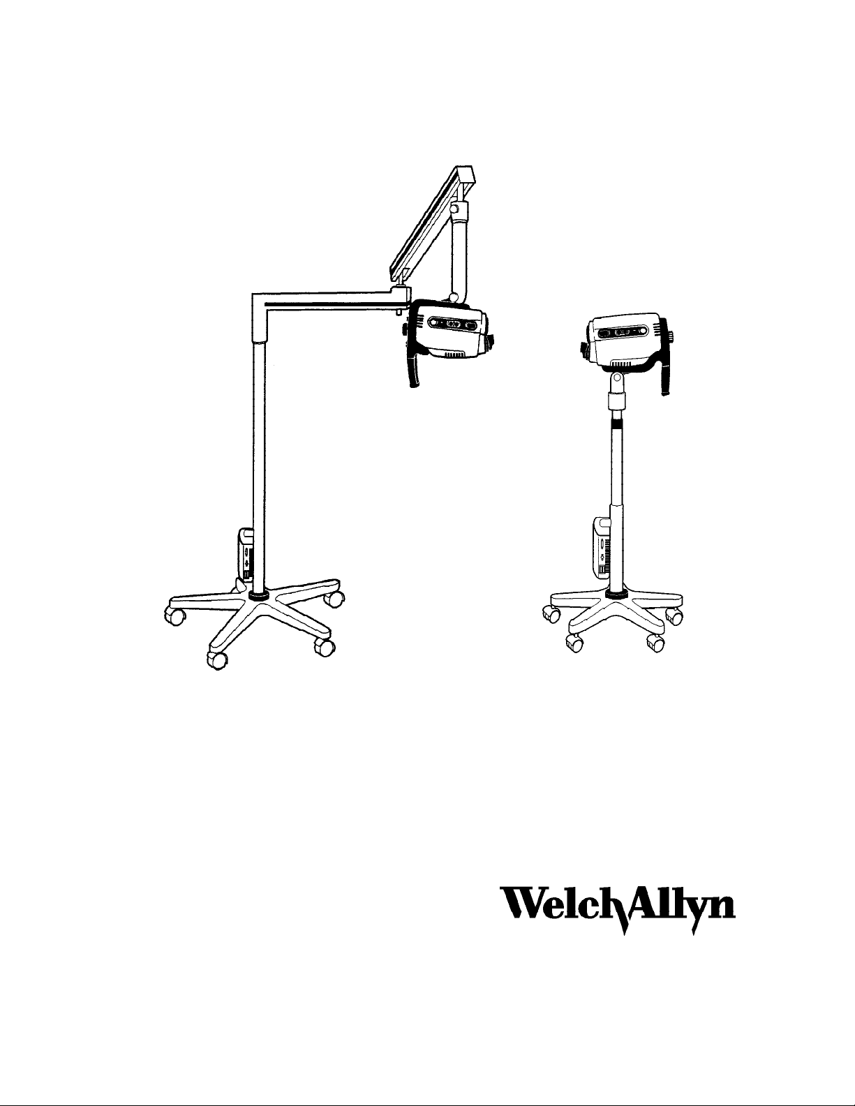
Video Colposcope
Models:
Vertical Pole: 880000, 88002, 88004, 88006
Swing Arm: 89000, 89002, 89004, 89006
™
Welch Allyn, Inc.
4341 State Street Road
P.O. Box 220
Skaneateles Falls, NY 13153-0220
Telephone: 315-685-4100
Page 2

Part No Rev Description ECN # Date Initiator
880220 A New Release 5-35922 7/97 R.Settembre
DRAWINGS AND/OR ILLUSTRATIONS AND/OR PART NUMBERS CONTAINED IN
THIS DOCUMENT ARE FOR REFERENCE PURPOSES ONLY! FOR CURRENT
REVISIONS CALL WELCH ALLYN.
i
Page 3

Table of Contents
Help Information ...........................................................................................................iii
Section 1: General Information ................................................................................ 1-1
1.1 General Precautions and Symbols ................................................................ 1-2
1.2 Summary of Warnings and Cautions ............................................................. 1-3
1.3 Basic System Description.............................................................................. 1-4
1.4 Product and Repair Bill Numbers .................................................................. 1-5
1.5 Recommended Initial Settings for Monitor.............................................. 1-6, 1-7
1.6 Cleaning ........................................................................................................ 1-8
Section 2: Service...................................................................................................... 2-1
2.1 Bench Test.............................................................................................. 2-2, 2-3
2.2 Required Tools............................................................................................... 2-4
2.3 Camera Alignment Information........................................................ 2-5, 2-6, 2-7
2.4 Hipot and Leakage Current Testing ............................................................... 2-8
Section 3: Problem Solving ...................................................................................... 3-1
3.1 Troubleshooting ............................................................................................. 3-2
Section 4: Disassembly and Repair ......................................................................... 4-1
4.1 Stand Alone Colposcope Disassembly Sequence......................... Photos 1- 37
4.2 Reference Photos for Reassembly ................................................ Photos 38-46
4.3 Handle Disassembly...................................................................... Photos 47-49
4.4 Pole Clutch Replacement .............................................................. Photos 50-52
4.5 Camera Alignment Procedure ....................................................... Photos 53-58
4.6 Power Supply ................................................................................ Photos 59-60
Section 5: Repair Parts Reference Drawings and Interconnect Diagrams
5.1 Stand Alone Colposcope Repair Parts and Drawing References. (5 pages)
5.2 Drawings
5.3 Interconnect Diagrams
ii
Page 4

Help Information:
¡ All service and repairs must be performed by authorized Welch Allyn personnel or agents,
using Welch Allyn replacement parts. Failure to do so will invalidate the product warranty.
¡ Customers in North America should return instruments requiring service to the Welch Allyn
Technical Service Department list below, or to an authorized Welch Allyn distributor.
Technical Service Department
Welch Allyn, Inc.
4341 State Street Road
Skaneateles Falls, NY 13153-0220
U.S.A.
Telephone: 800-535-6663
Fax: 315-685-4653
¡ Customers outside of North America should return their units to a local, authorized
Welch Allyn distributor, or to their nearest Welch Allyn service center. The part and
serial numbers are located on the housing of the colposcope near the fan. Remove
the colposcope from the handle to locate these numbers.
¡ Troubleshooting assistance is contained in Section 3 of this manual.
¡ Please read and understand Colposcope Users Manual P/N 880136, and all peripheral
equipment users manuals.
iii
Page 5

Thank you for purchasing the Welch Allyn Video Colposcope. Follow the operation
and maintenance instructions found in this manual and your video colposcope will
provide you with many years of reliable service. Please read these instructions thoroughly before attempting to use your new video colposcope.
CAUTION: Federal law restricts sale of this device to, or to the order of,
!
!
IMPORTANT: The material outlined in this manual should be reviewed and understood
prior to operation of the equipment.
NOTE: This equipment has been tested and complies with emissions standard
EN60601-1-2: 1993, CISPR Publication 11:1990/EN55011: 1991 for Radiated and
Conducted Emissions, Group 1, Class B.
a physician or other appropriately licensed medical professional.
WARNING: Users of this equipment should be thoroughly trained in the
appropriate medical procedures. Furthermore, they should take the
time to read and understand these instructions before performing any
procedure. They should also read and understand the instructions for
any other equipment used in conjunction with the video colposcope
(i.e. electrosurgical generators). Failure to do so may result in injury to
the patient and/or damage to the video colposcope.
This equipment also has been tested and complies with susceptibility standards to
electrostatic discharge (ESD), radiated electromagnetic fields, fast transient bursts, and
conducted surge interference. The procedures and criteria for conformance are contained in IEC801-2, 801-3, 801-4, 801-5, and EN60601-1-2: 1993.
In addition, this equipment has been tested and complies with EN6000-3-2 (1st Edition)
covering harmonic disturbances in supply systems caused by household appliances and
similar electrical equipment, Part 2, and EN 6000-3-3 (1st Edition) covering voltage
fluctuation disturbances in supply caused by household appliances and similar electrical
equipment Part 3.
INDICATIONS FOR USE: For examination of the tissues of the vagina, cervix, and
external genitalia, to investigate, by means of magnification, abnormal cervical cytology
or suspicious lesions of the lower female genital tract. Also used for corresponding
biopsy and treatment, when indicated.
NOTE: This device complies with the guidelines of the American Conference of Governmental Industrial Hygienists threshold limits values for ultraviolet radiation for exposure
time and distance consistent with the intended use of this device.
iv
Page 6

General Information
1.1 General Precautions and Symbols
1.2 Summary of Warnings and Cautions
1.3 Basic System Description
1.4 Product Numbers and Descriptions
1.5 Recommended Initial Settings for Monitor
1.6 Cleaning
Section 1
Stand Alone Colposcope Service Manual Page 1 - 1
Page 7
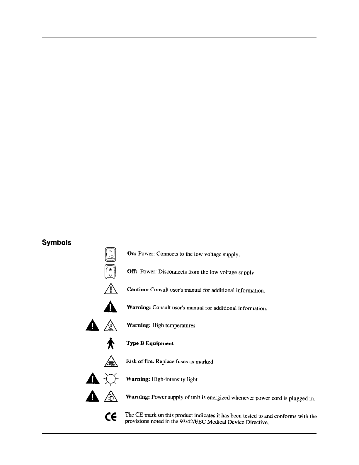
1.1 General Precautions and Symbols
General Precautions
For safety, the video colposcope should only be coupled to a grounded 110-120VAC hospital-grade outlet (220-240
volt, 50 cycle international).
The video colposcope should not be operated in the presence of flammable or explosive gases or chemicals, or
installed in areas where these materials are commonly used.
To avoid overheating, the video colposcope should not be positioned closer than 6" to any wall.
Keep all liquids away from electrical equipment to avoid the possibility of shock and instrument damage.
Occasionally inspect the power cord for signs of cuts, abrasions or dents.
The video colposcope should never be stored or operated in areas where it could get wet or could be exposed to any
environmental conditions like extreme temperature or humidity, direct sunlight, dust, etc.
The lamp is extremely bright. DO NOT stare directly into illumination lens when the lamp is lit.
All service to the video colposcope must be performed by Welch Allyn or by an authorized repair center.
Video colposcope user should adhere to the operating conditions found in this manual. Otherwise, instrument
damage may occur and/or operator/patient safety may be comprised.
There are no user serviceable parts (other than the lamp and fuses) in this unit or in its accessories. Any attempt to
disassemble and/or repair this unit will result in voiding of the warranty.
Stand Alone Colposcope Service Manual Page 1 - 2
Page 8

1.2 Summary of Cautions and Warnings
Stand Alone Colposcope Service Manual Page 1 - 3
Page 9

1.3 Basic System Description
The Stand Alone version is not a Video Path product and does not require a light source.
It is a camera and light source in one compact housing mounted on either a vertical pole
stand or a swing arm stand as shown in Figure 1. The table on Page 1- 6 is a list of
product numbers and repair bill numbers. It also lists the product numbers for the camera units only.
Fig. 1
Stand Alone Colposcope Service Manual Page 1 - 4
Page 10

1.4 Product Numbers and Descriptions
Product Number Repair Bill # Description/Format Market
(Burned-in & aligned camera)
88000 (88021 Camera/Pole 88021 Repair Vertical Stand with RS232 NTSC U.S.
with a 49555 Base) (Camera/Pole repair Camera Unit is PN 880080-501
bill)
88002 (88022 Camera/Pole 88022 Repair Vertical Stand with RS232 PAL Europe
with a 49555 Base) (Camera/Pole repair Camera Unit is PN 880080-502
bill)
88004 (88024 Camera/Pole 88024 Repair Vertical Stand with RS232 Pal United
with a 49555 Base) (Camera/Pole repair Camera Unit is PN 880080-502 Kingdom
bill)
88006 (88026 Camera/Pole 88026 Repair Vertical Stand with RS232 PAL Australia
with a 49555 Base) (Camera/Pole repair Camera Unit is PN 880080-502
bill)
89000 (89021 89021 Repair Swing Arm with RS232 NTSC U.S.
Camera/Swing Arm with a (Camera/Swing Arm Camera Unit is PN 880080-501
89050 Pole and a 89555 repair bill) (reposition toe clip for swing arm
Base) (3 cartons) attachment)
89002 (89022 89022 Repair Swing Arm with RS232 PAL Europe
(Camera/Swing Arm with a (Camera/Swing Arm Camera Unit is PN 880080-502
89050 Pole and a 89555 repair bill) (reposition toe clip for swing arm
base) (3 cartons) attachment)
89004 (89024 89024 Repair Swing Arm with RS 232 PAL United
Camera/Swing Arm with a (Camera/Swing Arm Camera Unit is PN 880080-502 Kingdom
89050 Pole and a 89555 repair bill) (reposition toe clip for swing arm
base) (3 cartons) attachment)
89006 (89026 89026 Repair Swing Arm with RS232 PAL Australia
Camera/Swing Arm with a (Camera/Swing Arm Camera Unit is PN 880080-502
89050 Pole and a 89555 repair bill) (reposition toe clip for swing arm
base) (3 cartons) attachment.)
89050 Repair Pole, Swing Arm Packaged
(repair bill for the
swing arm pole)
Stand Alone Colposcope Service Manual Page 1 - 5
Page 11
1.5 Recommended initial settings and connections for
Sony PVM-1350 Monitor
Stand Alone Colposcope Service Manual Page 1 - 6
Page 12

Factory “Default” Settings of Monitor:
Refer to PG 5 of Sony PVM-1350 Operating Instructions for complete details.
Menu Item Number:
1 Main Menu follow instructions
2 Chroma Set up menu Setting is OFF
3 Caption Vision menu Setting is OFF
4 User Config 1 menu follow instructions
5 User Config 2 menu follow instructions
6 Auto Adjust screen follow instructions
7 Color System Display menu setting is AUTO
8 V Hold Screen adjust only if necessary
9 RGB SYNC menu setting is SYNC ON G
10 NTSC Setup Level menu setting is 7.5
11 Language Menu setting is ENGLISH
Stand Alone Colposcope Service Manual Page 1 - 7
Description: Default Factory Setting:
Page 13
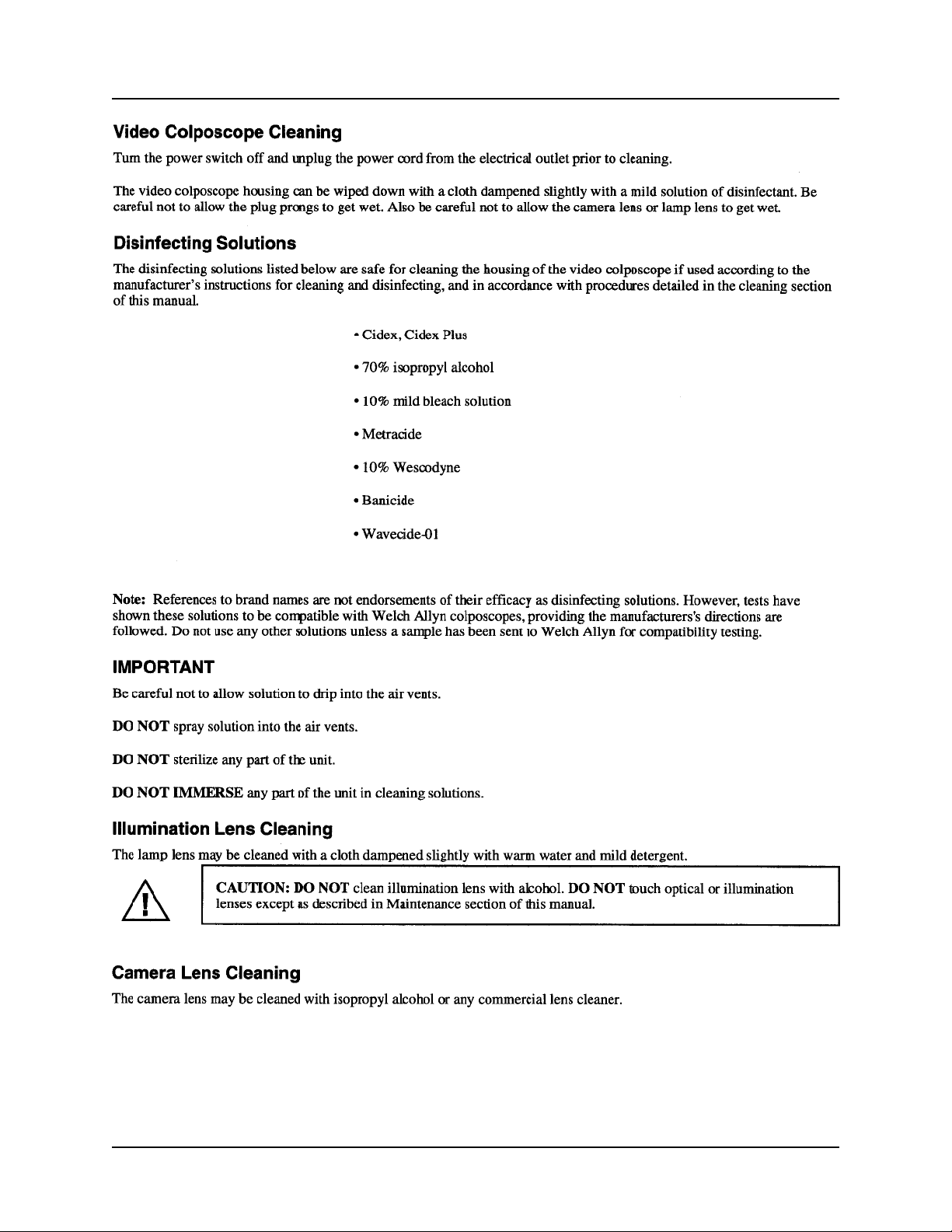
1.6 Cleaning
Stand Alone Colposcope Service Manual Page 1 - 8
Page 14

Service
2.1 Bench Test
2.2 Required Tools
2.3 Camera Alignment Procedure
2.4 Hi-Pot and Leakage Current Testing
Section 2
Stand Alone Colposcope Service Manual Page 2 - 1
Page 15

2.1 Bench Test
Bench Checks of the Stand Alone Video Colposcope
Perform the following functional checks of the colposcope when it is received for service
and after repair: Perform Video Colposcope cleaning per page 16 of Welch Allyn Video
Colposcope User’s Manual pn 880136 (reprinted in this service manual in Section 1.)
1 Perform physical examination of returned colposcope and accessory cables,
cords etc.
A) Make record of what components were received. Note serial numbers
where applicable.
B) Check the physical and electrical condition of all items including S-video
cables, power cords, RS232 cables, all pins and sockets.
C) Check the lamp connector. The lamp has a small and a large pin. Make
sure the lamp socket has not been ruined by someone connecting the
connector in reverse. This would damage the connector and make lamp
operation intermittent.
Connectors must fit lamp pins securely.
2 Connect Colposcope to monitor, and or other system components such as Video
Printerand perform test of colposcope functions listed below:
A Lamp
B Fan
C Lamp door micro switch safety function.
door. If lamp lights, then micro switch(s) are stuck or defective.
D Colposcope attachment
E Colposcope functions
unit to stabilize and focus. The camera will stabilize at zoom (-).
F Focus:
G Check video picture quality:
colors on the monitor are (visual reference) the same as the bar chart.
Verify that the image is free from any visible video noise.
H Check green filter operation:
into an out of the green filter mode. It will stay slighted while the green filter is on.
I Check the Light Director movement.
in three positions: 45 degrees left, right and back to center. Check the
projected spot for uniformity and no dark spots.
Stand Alone Colposcope Service Manual Page 2 - 2
operation
operation
Try to run unit without lamp
to pole or swing arm.
...allow approximately 10 seconds for the camera
Check focus, zoom
view a color bar chart and verify that the
the green filter led should flash as it changes
It should move freely and detent
Page 16

3 Check all mechanical fasteners for tightness.
Check all cords and cables for solid connections, (wiggle the connectors and
cords while the colposcope is operating and look for any breaks or static on the
monitor.)
4 Check the printer functions of the colposcope handle.
Verify
that the “F” button will freeze the live image as displayed on the monitor or
three beeps from the printer and “No Paper” text appears on the monitor and printer.
Verify
that the “C” button will print the frozen image displayed on the monitor.
Verify
that the “V” button will cause the monitor to alternately display the live
video then the still “frozen” image.
5 Check the stands (swing arm, and vertical pole, casters) for function and smooth
operation. Check the brakes...(Do they hold?)
6 Check lenses for scratches, fingerprints, smudges, dust, moisture.
Stand Alone Colposcope Service Manual Page 2 - 3
Page 17

2.2 Required List of Tools
1) Torx T-15 Driver for housing screws.
2) English Hex Key set for various hex head fasteners
3) One extra hex key
4) RS232 Interface Cable Welch Allyn order number 88500
5) Strap Wrench T-10913
6) Achromatic Lens Assembly Tool - T-14716
You must order the following to check out the Colposcope
Monitor: Service Equipment should include a monitor for your standard. This is
a Sony PVM 1350 (NTSC) or a Sony PVM-1450 QM (PAL).
Note: this is not an underscan monitor as is the Sony PVM-1351Q
AC120V 50/60Hz (NTSC/PAL/SECAM)
Printer:
1800MD (NTSC) or a Sony VP-1800 EPM (PAL).
Standard electronic hand tools and Digital Volt Ohm Meter will be required for basic
troubleshooting such as checking output voltages and continuity.
To check the RS232 functioning of the Colposcope. This is a Sony VP-
Stand Alone Colposcope Service Manual Page 2 - 4
Page 18

2.3 Camera Alignment Information
The information below is intended for those who wish to know how the camera is calibrated:
Sony Cameras Welch Allyn PN 880057 (NTSC) and PN 880057-1 (PAL) are processed
during manufacturing as follows:
Photo 1:
1. Camera is received from Sony with accessory connectors in a bag (background).
2. Camera has a small circuit board (upper left) attached by two small metric screws.
Camera as received from Sony
Before installing Sony Cameras Welch Allyn PN 880057 (NTSC) and PN 880057-1
(PAL) into a Colposcope camera chassis perform the following steps:
● Discard bag of connectors and remove and discard circuit board.
● Camera is now ready to be installed in chassis and have calibration (vignetting)
checked.
● Follow camera vignetting checking / calibration process described in Section 4
Photos 53 through 58.
Stand Alone Colposcope Service Manual Page 2 - 5
Page 19
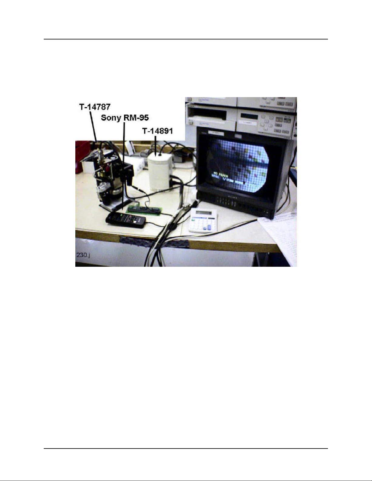
The test equipment required for checking and adjusting camera calibration (vignetting)
is shown below:
Call Welch Allyn for ordering details.
Camera Calibration (Vignetting) Equipment including: “Sony RE-95
Remote Commander for Adjustment,” suitable printers, and a Sony
PVM-1351Q AC 120 V 50/60 Hz Color Monitor
Stand Alone Colposcope Service Manual Page 2 -6
Page 20

2.3 Camera Alignment Information
Calibration of the Stand Alone Colposcope Camera:
A convenient service strategy regarding camera calibration is to stock one or two Colposcope Sub Assemblies (NTSC Colposcope Sub Assembly PN 880080-501, or PAL
Colposcope Sub Assembly PN 880080-502.) These Colposcope Sub Assemblies are
used as exchange units if a camera failure occurs. Exchange a failed Colposcope Sub
Assembly with a factory calibrated Colposcope Sub Assembly which has had Camera
Alignment Procedure performed at the factory.
This eliminates the need for calibration equipment at your facility. The camera alignment
procedure itself takes only six minutes, but requires additional equipment such as the
handheld remote control called a “Sony Remote Commander for Adjustment” and a
Sony Underscan monitor (for example, a Sony PVM-1351Q AC 120V 50/60 Hz Color
Monitor.) To switch vertical pole type mount to swing arm type mount, simply re-position
the toe piece. There is enough information in this manual to elect to equip your service
center with the necessary equipment and training to perform the alignment procedure.
But an Underscan monitor would have to be purchased instead of a non-Underscan
monitor.
The exchange process:
If a colposcope fails due to a failed camera follow the steps below:
● Your technician tests/diagnoses returned colposcope and determines failure is
due to bad camera.
● Technician removes the camera assembly (camera and chassis assembly) from
the customer’s housings and installs the factory aligned/burned-in camera
assembly from the exchange unit.
● The original housings maintain serialization for repaired colposcope. The unit is
tested and returned to owner.
● The failed Colposcope Sub Assembly is returned to Welch Allyn Medical Division
Technical Service Department, State Street, where the camera will be replaced
and calibrated. It will be returned to your depot parts inventory.
Stand Alone Colposcope Service Manual Page 2 - 7
Page 21

2.4 Hi-Pot and Leakage Current Testing
Hi-Pot and current leakage tests:
When electrical components have been changed, or if there is any reason
to believe that the unit will not meet safety specifications for HI-POT and
Leakage current, it is advisable to check HI-POT and Leakage current. If the
unit fails these tests, replace the faulty component(s) and re-test.
HI-POT Mains to ground specifications.
With the power switch to the “ON” position, the unit must withstand:
1.5KVAC for 1 second.
Leakage current test specifications.
Input voltage: 115 +/- 5 vac 60Hz
Turn the colposcope unit power switch to the “ON” position.
Verify lamp function- lamp is on.
Touch leakage probe of the tester to the following parts of the stands:
-Vertical pole model: Phillips screw on vertical pole (aluminum pole).
-Swing arm model: socket head cap screw at connection of horizontal arm to pole.
The leakage current shall not exceed 100 micro Amperes. ( .0001 Amps)
When testing in 230 volt countries, the unit must still adhere to the 100
micro Ampere limit on leakage current.
Stand Alone Colposcope Service Manual Page 2 - 8
Page 22

Problem Solving
3.1 Troubleshooting
Section 3
Stand Alone Colposcope Service Manual Page 3 - 1
Page 23

3.2 Troubleshooting Stand Alone Colp
Condition Check Action
Power does not come on Power Cord Check connections at power supply and
Fuses Remove fuse panel and replace blown
Attachment of unit to handle Check colposcope unit’s alignment with
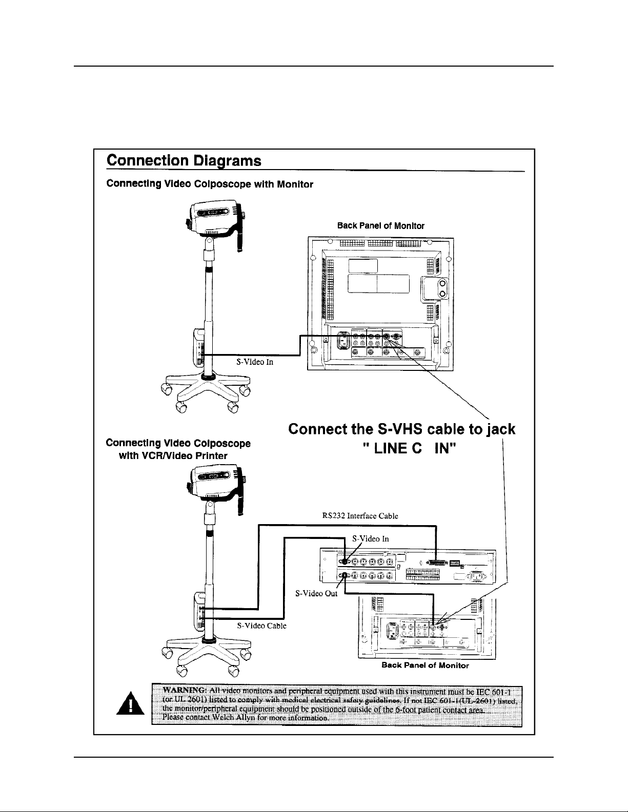
No image on monitor Attachment of unit to handle and door to Make sure lamp access door and handle
unit. are properly attached.
(Refer to Color Video Monitor Operating
Instructions) Monitor/other peripheral devices Make sure power is on for all devices.
Monitor input selection Make sure correct input selection is
Cable connections Make sure all video cables are
Lamp will not light Lamp Housing Make sure lamp assembly is installed
Lamp Replace lamp.
Lamp access door Make sure lamp access door is properly
wall outlet.
Plug the power cord into a wall outlet
known to work.
fuse with T1.00L 250 1A time lag.
handle.
made on the front panel. Make sure
Channel “C” is selected.
connected properly.
properly.
closed.
Lamp connector loose. Check socket for tight fit.
Printer does not respond properly to Power cord and printer Unplug power cord from wall outlet, then
handle buttons. plug cord back into outlet. At the same
(Refer to Color Video Printer Operating Printer Make sure printer is on and is properly
Instructions) connected.
Printer not set up properly Set Dip Switches to 9,600 Baud Rate
Black and White Image only Monitor of one video standard with Order correct standards
camera of another video standard.
Defective “S” Video Cable Replace with known good cable
Bent pin at camera, power supply or Replace connector.
cable connector.
S video cable not plugged in all the way. Restore good fit.
Wrong settings on monitor. Make sure Blue Only is not selected on
Rolling picture. S video cable connector damaged.
time, turn printer off and then on again.
Make sure correct input selection is
selected.
Switches 3 & 4 are “On”, all others are
“Off”
Reset printer by turning off then on again.
Sony VP 1800
monitor.
Have wall outlet checked “properly
grounded”
Note: For monitor default settings, refer to the Owners Manual included the monitor.
Stand Alone Colposcope Service Manual Page 3 - 2
Page 24

Disassembly and Repair
4.1 Stand Alone Colposcope Disassembly Sequence
4.2 Reference Photos for Reassembly
4.3 Handle Disassembly
4.4 Pole Clutch Replacement
4.5 Camera Alignment Procedure
4.6 Power Supply
Section 4
Stand Alone Colposcope Service Manual Page 4 - 1
Page 25

Photo 1:
1.1 Disconnect from Mains.
1.2 Unscrew knob
1.3 Separate camera from handle.
Photo 2:
Lamp area will be hot immediately after lamp
operation!!
Slide lamp access door away from the housing
and remove it.
Section 4
Photo 1
Photo 2
Photo 3:
Remove lamp.
Photo 3
Stand Alone Colposcope Service Manual Page 4 - 2
Page 26

Photo 4:
Carefully cut label at gap.
Photo 5:
Remove 4 torx screws using T-15
torx screwdriver.
Section 4
Photo 4
Photo 5
Photo 6:
Open covers first near lens. Then spread covers
apart from other side as in Photo 7.
Photo 6
Stand Alone Colposcope Service Manual Page 4 - 3
Page 27

Photo 7:
Open unit up this way to avoid stress on ribbon cables.
Photo 8:
Disconnect locking connector of left switch assembly.
(Left-switch ribbon cable attaches to the logic board
rear connector. The Right-switch ribbon cable attaches
to the logic board front connector.)
Section 4
Photo 7
Photo 8
Photo 9:
Gently pull light director from focusing sleeve.
Photo 9
Stand Alone Colposcope Service Manual Page 4 - 4
Page 28

Photo 10:
Unscrew Focusing sleeve from lamp housing.
Photo 11:
The glass rod/ferrule assembly may come
out with the focusing sleeve.
Section 4
Photo 10
Photo 11
Photo 12:
Do not lose the UV filter in the end of the
brass ferrule.
Photo 12
Stand Alone Colposcope Service Manual Page 4 - 5
Page 29

Photo 13:
Note: Replacement focusing sleeves
must be pre-focused as shown.
First: Rotate and measure gap.
Second: Apply Loctite 495 around
inner sleeve (except in the large rotating
slot area) to fix gap measurement shown.
Photo 14:
At this point, the Right Side Control Pad (switch)
assembly is accessible. It is held in place by six
screws.
The Left Side Control Pad will be accessible once
the camera assembly is removed in a later Photo.
Section 4
Photo 13
Photo 14
Photo 15:
To convert a vertical pole Colposcope to a
Swing Arm Colposcope: Move toe piece to
the alternate position.
Heat the screws with the tip of soldering iron
to loosen threadlocking glue.
Photo 15
Stand Alone Colposcope Service Manual Page 4 - 6
Page 30

Photo 16 & 17:
Unfasten camera by removing three Torx
screws. Two rear screws shown.
Section 4
Photo 16
Photo 17
Photo 18:
Remove third screw under ferrite bead.
Photo 18
Stand Alone Colposcope Service Manual Page 4 - 7
Page 31

Photo 19:
Before lifting camera out of housing,
disconnect the Left Control Pad assembly
connector from logic board front connector.
Photo 20:
Lift camera from Left Housing.
Note: the camera wiring harness, consisting
of pre-wired: fan, thermal cut out, DB-9
connector, and microswitches, can be replaced now if necessary. See photo 21 below
regarding thermal cut out removal.
Section 4
Photo 19
Photo 20
Photo 21:
Important: Do not lose the fiber washer during
removal of thermal cut out. This washer
prevents the head of the screw from breaking
the epoxy on the thermal cut out which would
create a circuit from the thermal cut out
directly to ground via the screw. This fault will
damage the power supply.
During reassembly make sure the fiber
washer is properly positioned over the thermal cut out as shown. Use threadlocker
Locktite 222 on the screw. Do not overtighten.
Photo 21
Stand Alone Colposcope Service Manual Page 4 - 8
Page 32

Photo 22:
Remove four screws. Do not lose 4 board
spacers.
Photo 23:
Remove board, spacers, and insulator.
Section 4
Photo 22
Photo 23
Photo 24:
The lens is accessible when the camera is
free of the housing as shown in previous Photo
20. Unscrew lens.
Photo 24
Stand Alone Colposcope Service Manual Page 4 - 9
Page 33

Photo 25:
Optical characteristics are identical for either of the
lenses used in production colposcopes to date.
Photo 26:
This lens adapter is required when the lens on
the left in Photo 25 is used.
Section 4
Photo 25
Photo 26
Photo 27:
Both lenses in Photo 25 use the same Achromatic Lens assembly (on left).
It is made up of:
PN880018 lens holder (outer shell)
PN880059 achromatic lens
PN880019-1 Ring, lens (retaining ring)
Tool T-14716 hand tightens the retaining ring.
Photo 27
Stand Alone Colposcope Service Manual Page 4 - 10
Page 34

Photo 28:
For Logic board access, remove two camera
shield screws......
Photo 29:
......lift camera shield straight up.
Section 4
Photo 28
Photo 29
Photo 30:
Logic board is now accessible.
Disconnect connectors.
Photo 30
Stand Alone Colposcope Service Manual Page 4 - 11
Page 35

Photo 31:
Remove Logic board.
Camera is now accessible.
Photo 32:
To remove camera unit:
Disconnect connector with ferrite bead.
Section 4
Photo 31
Photo 32
Photo 33:
Remove three camera holding screws.
Photo 33
Stand Alone Colposcope Service Manual Page 4 - 12
Page 36

Photo 34:
Disconnect 3-wire connector (foreground).
Disconnect 2-wire connector (background).
NOTE: When reassembling the camera shield
(Photo 29) to camera chassis, do not dislodge the
2 wire connector.
Photo 35:
Press tab (see inset) and hold down.
(attach lens to aid with pulling camera.)
Photo 35 Inset
Section 4
Photo 34
Photo 35
Photo 36:
Gently pull camera from chassis.
Photo 36
Stand Alone Colposcope Service Manual Page 4 - 13
Page 37

Section 4
Photo 37:
Colposcope disassembly is complete.
Photo 37
The Colposcope can be reassembled in reverse order. Reference photos are included to assist in
reassembly and clearly show critical position and placement of wiring within the colposcope housings.
Reference Photos: Techniques for Reassembly:
Reassembly reference Photo 38:
Camera ribbon cable placement.
Photo 38
Reassembly reference Photo 39:
Microswitch wiring and ferrite bead.
(focusing sleeve is removed in this photo)
Photo 39
Stand Alone Colposcope Service Manual Page 4 - 14
Page 38

Reassembly reference Photo 40:
This four step process makes it easy to install the ballast board
onto the spacers and insulator.
Lay parts out as shown.
Assemble as shown in photos 41 through 43.
Reassembly reference Photo 41:
Lower ballast board onto spacers and insulator.
Section 4
Photo 40
Reassembly reference Photo 42:
Grasp insulator and lift parts up.
Reassembly reference Photo 43:
Lower parts onto chassis and tighten screws.
Photo 41
Photo 42
Photo 43
Stand Alone Colposcope Service Manual Page 4 - 15
Page 39

Reassembly reference Photo 44:
Make sure the camera shield is placed underneath the camera chassis during reassembly.
Do not dislodge 2 wire connector (see Photo 34)!
If it comes loose all video will be lost (black
screen).
Reassembly reference Photo 45:
Wire path for lamp socket.
Section 4
Photo 44
Photo 45
Reassembly reference Photo 46:
Right housing: Ribbon cable fold and correct path.
Photo 46
Stand Alone Colposcope Service Manual Page 4 - 16
Page 40

Photo 47:
Carefully cut old cover and discard
Photo 48:
Remove: 4 Torx screws, 2 Phillips screws.
Section 4
Photo 47
Photo 48
Photo 49:
Open handle carefully. Switches are now accessible.
Photo 49
Stand Alone Colposcope Service Manual Page 4 - 17
Page 41

Photos 50/51:
Vertical Pole Clutch Removal/ Replacement:
If height adjustment does not hold or is jammed,
replace the clutch.
Remove old clutch with explorer or suitable tool.
Photo 51:
Do not scratch pole!
Section 4
Photo 50
Photo 51
Photo 52:
Remove flashing (if any) from long edges of
clutch material by edge sanding.
Put new clutch into ring.
Photo 52
Stand Alone Colposcope Service Manual Page 4 - 18
Page 42

Camera Alignment Procedure:
Photo 53:
Replacement camera units should be checked
before reassembly. The fixtures shown are
available from Welch Allyn.
53.1 Place Camera/Frame assembly
overposts of Camera Alignment Fixture in
Photo 53 inset.
Do not overtighten knob!
Photo 53i
53.2 Set the Sony Trinitron Color Video
Monitor (T-14891) as follows:
contrast - detent position, underscan
setting, aperture-center position, volume
- n/a, bright - detent position, chromadetent position, C/SDI - on position, all
other - off position
Section 4
Photo 53
53.3 Connect the S-video cord from Camera
Test Power Supply to the monitor.
Photo 54:
Connect the Test Power Supply (T-14891) D9
Connector to the test Camera Assembly
Allow approx. 10 seconds for the camera unit to
stabilize and focus. (the camera will stabilize at
zoom ( - ))
Photo 54
Stand Alone Colposcope Service Manual Page 4 - 19
Page 43

Photo 55:
Plug the test keypad (see inset photo 55i) into
one of the two keypad connectors on the logic
board as shown.
Photo 56:
56.1 Use the focus button to adjust the focus
so that the achromat lens ring ( black )
and the alignment grid are both in crisp
focus.
Section 4
Photo 55Photo 55i
56.2 If image appears centered on the monitor
and symmetrical as shown in photo 56 (9
boxes on each side), no adjustment of the
camera is necessary. See explanation
below.
Photo 56
DETERMINING IF ADJUSTMENT IS NECESSARY:
If the image has more boxes on one side than the other, the vignetting might not meet the specifi-
cation ratio of “Less than 1:2.25”. To determine the ratio of your camera unit, count the number of boxes
on each side of the image and divide the greater number by the smaller number. For example, Photo 56
shows 9 grid boxes on the left and right sides. This is a ratio of 1:1 which meets the specification. Our
example requires no “vignetting” adjustment.
If the right side had 3 boxes and the left side had 14 boxes, (14 divided by 3) the ratio would be
1:4.666 which does not meet specifications. LEFT RIGHT vignetting must be adjusted. Follow proce-
dure starting at Photo 57 to adjust LEFT RIGHT vignetting. There is no UP DOWN vignetting adjustment. If the camera can not be brought into specifications, it is defective and must not be used.
Stand Alone Colposcope Service Manual Page 4 - 20
Page 44

Photo 57:
Disconnect the 3 wire connector (camera to Logic
board).
Photo 58:
58.1 Attach the RM-95 remote commander to
the 3 pin connector on Logic board.
58.2 Set the remote commander Norm-adj
button to the adj. position. (button located
in the upper left corner)
58.3 The RM - 95 will display some value as
soon as you connect it to the camera. In
this example, (Photo 58) the RM-95
displays a Page “F”, a Data value “3E”,
and an address “0c”. It looks like this:
“F:3E:0c”
Section 4
Photo 57
58.4 You must re-set it as follows before
making adjustments:
Use edit search (+) button to set “page”
to “01”
58.5 Press the “play” button to set “data” to
“01” (Use “stop” button to count down if you go past “01”)
58.6 Use edit search (+) button to set “page” to “0D”
58.7 Use the “FF” button to set the “address” to “04”
58.8 Record the initial/original camera data settings.
58.9 Use the “PLAY” button to increase data value and the “STOP” button to decrease data value
while watching the picture move. Find the optimum data value which centers the image
horizontally using one or both of the following:
58.10 Adjust the white area along the left/right side of the monitor to be as close to equal in sizeand
symmetrical as possible.
58.11 Calculate the white ratio (length of the white area)
Example: LSW = 12 divisions, RSH = 16 divisions, 16/12 = 1.34
58.12 Compare the adjusted value to the acceptable value range of 1: 2.25
58.13 If the adjusted value is acceptable - save the data PRESS “ORANGE PAUSE” button. If the
value is not acceptable - readjust if possible, otherwise do not use the camera unit. Record the
data value displayed.
58.14 Disconnect the RM-95 unit from the camera and reconnect the camera harness cable to the
camera board.
Calibration (vignetting adjustment) is complete.
Photo 58
Stand Alone Colposcope Service Manual Page 4 - 21
Page 45

Power Supply Repair
Photo 59:
Remove four screws on the back of the power supply.
Note: The pole itself is not repairable. If the internal
cord is defective, replace the pole assembly.
Photo 60:
Replace the Svideo Jack if defective or if it has all
green wires. Unscrew jack and disconnect Molex
connector.
Section 4
Photo 59
Photo 60
Stand Alone Colposcope Service Manual Page 4 - 22
Page 46

Section 5
Repair Parts Reference Drawings and Interconnect
Diagrams
5.1 Stand Alone Colposcope Repair Parts and Drawing References. 5 pgs.
(Recommended Inventory per ten units in your customer base is column
“Inv./10”.)
5.1 Drawings
5.3 Interconnect Diagrams
Stand Alone Colposcope Service Manual Page 5 - 1
Page 47

5.2 Drawings
Drawing Number Drawing Description
D-8800198 Interconnect Diagram, Vert.
D-8900058 Interconnect Diagram, Swing Arm
880000 Colposcope Vert. Dom
880039 Colposcope Vert. UK, AUS, EUR
880045 Vertical Pole Assembly
880080 Colposcope Sub Assembly PAL & NTSC
880091 Assembly Wire Harness
880140 Colp & Vert Pole Assembly PAL & NTSC
890015 Arm Assembly
890018 Assembly Pole and Swing Arm
890038 Colp. & Swing Arm - PAL
890055 Pole Swing Arm Packaged
890056 Colp and Swing Arm NTSC
890057 Colp Swing Arm AUS, EUR, UK
Stand Alone Colposcope Service Manual Page 5 - 2
Page 48

Stand Alone Colposcope Service Manual Page 5 - 3
Page 1
098100 880080 2 3 LAMP ASSY (20W) 5 ✔ ✔ ✔ ✔ ✔ ✔ ✔ ✔
106100-11 880080 2 5 PHPS 4-40 X.312 6 ✔ ✔ ✔ ✔ ✔ ✔ ✔ ✔
106100-17 880080 2 4 PHPS 2-56 X.312 6 ✔ ✔ ✔ ✔ ✔ ✔ ✔ ✔
106101-1 880045 2 4 RETAINING RING 6 ✔ ✔ ✔ ✔ ✔ ✔ ✔ ✔
106101-19 880045 2 5 LOCK RING 6 ✔ ✔ ✔ ✔
106102-21 880045 2 6 FHPS #8-32 X .375 6 ✔ ✔ ✔ ✔ ✔ ✔ ✔ ✔ ✔
106102-22 880045 2 7 #2-56 FHPS (BLK) X .250 6 ✔ ✔ ✔ ✔ ✔ ✔ ✔ ✔
106102-24 880045 2 8 6-32 X .250 6 ✔ ✔ ✔ ✔ ✔ ✔ ✔ ✔
106102-26 880140 1 1 6-32 X .75 6 ✔ ✔ ✔ ✔ ✔ ✔ ✔
106102-4 880140 1 2 FHPS 6-32 X .375 LG 6 ✔ ✔ ✔ ✔ ✔ ✔ ✔ ✔
106102-7 880045 2,3 9 FLAT HEAD SCREW 6 ✔ ✔ ✔ ✔
106103-11 THERMAL WASHER 6 ✔
106103-21 880045 3 10 WASHER 6 ✔ ✔ ✔ ✔ ✔
106103-28 880045 2 11 WASHER, PIVOT 6 ✔ ✔ ✔ ✔ ✔ ✔ ✔ ✔
106103-34 880045 2 12 FLAT WASHER 6 ✔ ✔ ✔ ✔ ✔ ✔ ✔ ✔
106103-35 880045 3 13 WASHER, PIVOT 6 ✔ ✔ ✔ ✔ ✔ ✔ ✔
106103-42 880080 2 64 WASHER, FLAT .120 X .250 X .035 6 ✔ ✔ ✔ ✔ ✔ ✔ ✔ ✔
106105-3 880080 2 62 #4 LOCKWASHER, HEL 6 ✔ ✔ ✔ ✔ ✔
106106-2 880080 2 7 #4 INTRNL TOOTH LOCKWASHER 6 ✔ ✔ ✔ ✔ ✔ ✔ ✔ ✔
106106-4 890015 3 9 EXTRNL LOCKWASHER 6 ✔ ✔ ✔ ✔
106108-26 880045 3 14 O-RING 6 ✔ ✔ ✔ ✔
106108-27 O-RING 6 ✔ ✔ ✔ ✔
106108-3 880045 3 15 O-RING 6 ✔ ✔ ✔ ✔ ✔ ✔ ✔
106109-12 890015 3 11 HEX NUT 6 ✔ ✔ ✔ ✔
106113-19 880045 2 17 SET SCREW, 8-32 X.187 CONE 12 ✔ ✔ ✔ ✔ ✔ ✔ ✔ ✔
106113-6 880080 2 9 #4-40 SOCKET SET SCREW 12 ✔ ✔ ✔ ✔ ✔ ✔ ✔ ✔
106115-10 890015 2 13 SPRING, COMPRESSION 6 ✔ ✔ ✔ ✔
106119-18 890018 1 4 8-32 X .375 LG SHCS-SS 12 ✔
106119-24 SHCS 4-40 X .500 12 ✔ ✔ ✔ ✔
106120-5 880140 1 3 6-32 X.375 FLSTR HD PLASTIC 6 ✔ ✔ ✔ ✔ ✔ ✔ ✔ ✔
106120-6 880045 2 18 6-32 X.250 FILL; HD-BLK 6 ✔ ✔ ✔ ✔ ✔ ✔ ✔ ✔
106120-7 880045 3 19 #4-40 X.375 FILHD PHPS 6 ✔ ✔ ✔ ✔ ✔
106121-18 880045 2,3 20 .062 SHRINK TUBING 6 ✔ ✔ ✔ ✔ ✔ ✔ ✔ ✔ ✔
106121-19 880045 2 21 .187 SHRINK TUBING 6 ✔ ✔ ✔ ✔ ✔ ✔ ✔ ✔ ✔
106123-18 880080 2 11 SCREW M2 X 6MM 6 ✔ ✔ ✔ ✔ ✔ ✔ ✔ ✔
106124-18 880045 3 22 #8 X 1.25 SELF TAPPING SCREW 6 ✔ ✔ ✔ ✔ ✔
106124-21 #4X.375 PLASTITE SCREW 6 ✔
106124-26 880080 1 12 #6 X 2.00 PLASTITE TORX 6 ✔ ✔ ✔ ✔ ✔ ✔ ✔ ✔
106124-27 880045 1,3 23 #6 X .375 PLASTITE TORX 6 ✔ ✔ ✔ ✔ ✔ ✔ ✔ ✔ ✔
106126-21 880045 2 24 DOWEL PIN .062 X .375 6 ✔ ✔ ✔ ✔ ✔ ✔ ✔
106126-24 880045 2 25 DOWEL PIN .094 X.312 6 ✔ ✔ ✔ ✔
106126-25 PIN, DETENT 6 ✔ ✔ ✔ ✔
Part # Drawing# Page Bubble# Part Description Inv. /10 88021 88022 88024 88026 89021 89022 89024 89026 89050 49555 89555
Stand Alone Colposcope Repair Parts and Drawing Reference
Page 49

Stand Alone Colposcope Service Manual Page 5 - 4
Page 2
106126-26 880045 2 26 DOWEL PIN 6 ✔ ✔ ✔ ✔ ✔ ✔ ✔
106128-8 880080 2 15 1/4 SPACER 6 ✔ ✔ ✔ ✔ ✔ ✔ ✔ ✔
106129-8 880045 3 27 RING TERMINAL 12 ✔ ✔ ✔ ✔
106140-2 880045 3 28 4-40 W/EXT WASHER 6 ✔ ✔ ✔ ✔ ✔ ✔ ✔ ✔ ✔
106140-3 4-40 X .25 W/EXT WASHER 6 ✔ ✔ ✔ ✔ ✔ ✔ ✔ ✔ ✔
106148-1 880080 2 17 2-56 X .437 W/INT WASHER 6 ✔ ✔ ✔ ✔ ✔ ✔ ✔ ✔
236614-1 880045 2 96 WIRE, 20AWG,BROWN 6 ✔ ✔ ✔ ✔
23670-3117 FUSE 24 ✔
236729-6 880045 3 94 WIRE, 24AWG,BROWN 6 ✔ ✔ ✔ ✔
236729-7 880045 3 95 WIRE, 24AWG 6 ✔ ✔ ✔ ✔
265007 880045 3 29 2-56 X 1/8 LG SET SCREW 6 ✔ ✔ ✔ ✔ ✔
441113 880045 3 31 MOUNT SPACER 1 ✔ ✔ ✔ ✔ ✔
483017 880045 3 32 PHPS 6-32 X 5/16 2 ✔ ✔ ✔ ✔ ✔
485642 890060 1 1 CASTER WITH BRAKE 3 ✔ ✔
485642-1 890060 1 1 CASTER WITHOUT BRAKE 3 ✔ ✔
488307-9 880045 3 97 FUSE-1000 MA 24 ✔ ✔ ✔ ✔
488400-501 880080 2,3 18 FOCUSING SLEEVE ASS’Y 2 ✔ ✔ ✔ ✔ ✔ ✔ ✔ ✔
495075 880080 2 19
BALLAST SIDE CONN ASSY C12A003
4 ✔ ✔ ✔ ✔ ✔ ✔ ✔ ✔
495734 495555 1 CARTON INSERT 1 ✔
745070 880045 2 33 CLOSED END CONNECTOR 12 ✔ ✔ ✔ ✔
745150 880045 3 34 STRAIN RELIEF 4 ✔ ✔ ✔ ✔ ✔
761076-0 880000 1 4
POWER CORD, DETACH.(DOM/JAPAN)
4 ✔ ✔
761076-2 890057 1 2
POWER CORD-DETCHBL (EUROPEAN)
4 ✔ ✔
761076-4 890057 1 2 POWER CORD-DETCHBL(U.K) 4 ✔ ✔
761076-6 890039 1 2
POWER CORD DETACH. (AUSTRALIA)
4 ✔ ✔
761077-1 880045 2 35 TIE WRAP 24 ✔ ✔ ✔ ✔ ✔ ✔ ✔ ✔ ✔
785012-1 880045 3 36 SELF TAPPING SCREW .37 4 ✔ ✔ ✔ ✔ ✔
790043 880045 3 37 4-40 X .250 HEX NUT 6 ✔ ✔ ✔ ✔ ✔ ✔ ✔ ✔ ✔
880006 PIVOT, PITCH 2 ✔ ✔ ✔
880006-1 880045 2 42 PIVOT, PITCH FINISHED 6 ✔ ✔ ✔ ✔ ✔ ✔ ✔ ✔
880007-1 880045 2 43 HUB, POWDER COATED 2 ✔ ✔ ✔ ✔ ✔ ✔ ✔ ✔
880008 880045 2 44 COLLAR, FRICTION 6 ✔ ✔ ✔ ✔ ✔ ✔ ✔ ✔
880009-4 890045 2 45 MOUNT, CLIP, PAINTED 2 ✔ ✔ ✔ ✔ ✔ ✔ ✔ ✔
880010 880045 2 46 SHAFT, PITCH BRAKE 2 ✔ ✔ ✔ ✔ ✔ ✔ ✔ ✔
880011 880045 2 47 BRAKE PAD 4 ✔ ✔ ✔ ✔ ✔ ✔ ✔ ✔
880012 880045 2 48 BRAKE, STATIONARY 4 ✔ ✔ ✔ ✔ ✔ ✔ ✔ ✔
880013 880045 2 49 SLEEVE, BRAKE 6 ✔ ✔ ✔ ✔ ✔ ✔ ✔ ✔
880015-1 880045 2 50 SLEEVE, HUB FINISHED 2 ✔ ✔ ✔ ✔ ✔ ✔ ✔ ✔
880016-1 880045 2 51 SHAFT, POWDER COATED 1 ✔ ✔ ✔ ✔
880018 880080 2,3 22 LENS HOLDER 2 ✔ ✔ ✔ ✔ ✔ ✔ ✔ ✔
880019 RING, LENS 1 ✔ ✔ ✔ ✔
880019-1 880080 2,3 23 RING, LENS FINISHED 1 ✔ ✔ ✔ ✔ ✔ ✔ ✔ ✔
Part # Drawing# Page Bubble# Part Description Inv. /10 88021 88022 88024 88026 89021 89022 89024 89026 89050 49555 89555
Stand Alone Colposcope Repair Parts and Drawing Reference
Page 50

Stand Alone Colposcope Service Manual Page 5 - 5
Page 3
880021 880045 3 52
PWR SUPPLY MOUNT W/PEM STNDOFF
0.0 ✔ ✔ ✔ ✔ ✔
880022 880045 2 53 SHAFT, COLP ATTACHMENT 0.0 ✔ ✔ ✔ ✔ ✔ ✔ ✔ ✔
880023 890019 2 19 STOP, STAND, ROTATION 0.0 ✔
880023-1 880045 3 54 STOP, BLK ANODIZED 1 ✔ ✔ ✔ ✔
880028 880080 2,3 24 FERRULE, GLASS ROD 1 ✔ ✔ ✔ ✔ ✔ ✔ ✔ ✔
880029 880140 1 4 TOE, COLP 4 ✔ ✔ ✔ ✔ ✔ ✔ ✔ ✔
880030 880080 2 25 LAMP MOUNT 0.0 ✔ ✔ ✔ ✔ ✔ ✔ ✔ ✔
880031 880045 3 59 POWER SUPPLY 40 WATT 2 ✔ ✔ ✔ ✔ ✔
880034 880045 3 60
WIRE HARNESS, RECPT TO PWR SUPP
1 ✔ ✔ ✔ ✔ ✔
880041-1 880045 2 62 COLLAR, BLK ANODIZE 1 ✔ ✔ ✔ ✔
880042 880045 2 63 CLUTCH, NYLON 6 ✔ ✔ ✔ ✔
880045-501 880140 1 5 VERTICAL POLE ASSY 0.0 ✔ ✔ ✔ ✔
880046 880045 2 64 KNOB W/CAP 1 ✔ ✔ ✔ ✔ ✔ ✔ ✔ ✔
880049 880045 1,2,3 65 ON/OFF SWITCH 2 ✔ ✔ ✔ ✔
880051 880045 2 66 CONNECTOR, D9 FEMALE 1 ✔ ✔ ✔ ✔
880055 880080 2 26 FRAME 0.0 ✔ ✔ ✔ ✔ ✔ ✔ ✔ ✔
880057 880080 2 27 CAMERA (NTSC) 0.0 ✔ ✔
880057-1 880080 2 27 CAMERA (PAL) 0.0 ✔ ✔ ✔ ✔ ✔ ✔
880058 880080 2 28 2X CONVERTER 1 ✔ ✔ ✔ ✔ ✔ ✔ ✔ ✔
880059 880080 2,3 29 ACHROMAT LENS 1 ✔ ✔ ✔ ✔ ✔ ✔ ✔ ✔
880060 880080 2,3 32 GLASS ROD 1 ✔ ✔ ✔ ✔ ✔ ✔ ✔ ✔
880061 880080 2 33 LAMP SPRING 4 ✔ ✔ ✔ ✔ ✔ ✔ ✔ ✔
880062 880080 2 34 21W BALLAST (JR43205119-01) 4 ✔ ✔ ✔ ✔ ✔ ✔ ✔ ✔
880064 880080 2 35 INSULATOR, BALLAST 4 ✔ ✔ ✔ ✔ ✔ ✔ ✔ ✔
880068-501 880080 2 36 LOGIC BOARD 2 ✔ ✔ ✔ ✔ ✔ ✔ ✔ ✔
880070 880140 1 6 TOE CAP 2 ✔ ✔ ✔ ✔ ✔ ✔ ✔ ✔
880073-1 880080 3 37 HOUSING, LEFT PRINTED 0.0 ✔ ✔ ✔ ✔ ✔ ✔ ✔
880074-1 880080 3 38 HOUSING, RIGHT PRINTED 0.0 ✔ ✔ ✔ ✔ ✔ ✔ ✔ ✔
880075-503
880080 3 39 LEFT CONTROL PAD ASSY 1 ✔ ✔ ✔ ✔ ✔ ✔ ✔
880075-504
880080 3 40 RIGHT CONTROL PAD ASSY 1 ✔ ✔ ✔ ✔ ✔ ✔ ✔ ✔
880079 880080 3 41 LAMP DOOR 3 ✔ ✔ ✔ ✔ ✔ ✔ ✔ ✔
880080-501 880000 1 8 COLPOSCOPE SUB ASSY (NTSC) 2 ✔ ✔
880080-502
880140 1 7 COLPOSCOPE SUB ASSY (PAL) 2 ✔ ✔ ✔ ✔ ✔ ✔
880083 880080 2,3 42 UV FILTER 4 ✔ ✔ ✔ ✔ ✔ ✔ ✔ ✔
880084 880045 2 67 KNOB, COLP ATTACHMENT 2 ✔ ✔ ✔ ✔ ✔ ✔ ✔ ✔
880086 880045 2 68 SHAFT, YAW BRAKE 1 ✔ ✔ ✔ ✔ ✔ ✔ ✔ ✔
880087-1 880045 3 69 FLANGE, FINISHED 2 ✔ ✔ ✔ ✔
880089 880080 3 43 WIRE HARNESS RT CONTROL PAD 1 ✔ ✔ ✔ ✔ ✔ ✔ ✔ ✔
880090 880080 3 44 WIRE HARNESS, LEFT CONTROL 1 ✔ ✔ ✔ ✔ ✔ ✔ ✔ ✔
880091 880080 2 45 WIRE HARNESS, CAMERA 1 ✔ ✔ ✔ ✔ ✔ ✔ ✔ ✔
880094 880045 1 70 GRIP 6 ✔ ✔ ✔ ✔ ✔ ✔ ✔ ✔
880099 880045 3 71 IRC POWER ENTRY MODULE 1 ✔ ✔ ✔ ✔ ✔
Part # Drawing# Page Bubble# Part Description Inv. /10 88021 88022 88024 88026 89021 89022 89024 89026 89050 49555 89555
Stand Alone Colposcope Repair Parts and Drawing Reference
Page 51

Stand Alone Colposcope Service Manual Page 5 - 6
Page 4
880102 890015 3 35 HOUSING,DUAL ROW 1 ✔ ✔ ✔ ✔
880102-1 880045 3 72 CONNECTOR, 4PIN 6 ✔ ✔ ✔ ✔ ✔ ✔ ✔ ✔
880103 880045 3 73 TERMINAL CRIMP 6 ✔ ✔ ✔ ✔ ✔ ✔ ✔ ✔
880104 880045 3 74 CRIMP TERMINAL HOUSING 6 ✔ ✔ ✔
880105 880045 3 75 TERMINAL,CRIMP 12 ✔ ✔ ✔ ✔
880106-501 880045 3 76 PC BOARD, RS232 2 ✔ ✔ ✔ ✔ ✔
880107 880045 3 77 WIRE HARNESS,RESISTOR 1 ✔ ✔ ✔ ✔ ✔
880108 880045 2 78 STIFFENER, HANDLE (VERT) 1 ✔ ✔ ✔ ✔
880109-1 880045 3 79 HOUSING, 4PIN 2 ✔ ✔ ✔ ✔
880109-2 880045 3 80 HOUSING, 2PIN 2 ✔ ✔ ✔ ✔
880110 880045 2,3 81 CONTACT PIN 12 ✔ ✔ ✔ ✔
880120 880045 3 82 SHIELD, POWER SUPPLY 0.0 ✔ ✔ ✔ ✔ ✔
880121 880045 3 83 LATCH BLOCK KIT 1 ✔ ✔ ✔ ✔ ✔
880122 880080 2 46 CAMERA SHIELD 0.0 ✔ ✔
880130-501 880045 3 84 ASY, LIGHT DIRECTOR 1 ✔ ✔ ✔ ✔ ✔ ✔ ✔ ✔
880131-1 890018 2 26 COVER, FERRITE FINISHED 1 ✔ ✔ ✔ ✔ ✔
880133-1 890015 3 38 BEAD FERRITE 1 ✔ ✔ ✔ ✔
880133-2 880045 3 85 BEAD FERRITE 1 ✔ ✔ ✔ ✔
880134 880045 2 86 PIN, CONNECTOR 12 ✔ ✔ ✔ ✔
880135 880039 1 4 WARRANTY CARD 4 ✔ ✔ ✔ ✔ ✔ ✔ ✔
880136 880000 1 10 INSTRUCTION MANUAL 4 ✔ ✔ ✔
880137-501 880039 1 6 CARTON, W/INSERTS, VERT 1 ✔ ✔ ✔
880141-501 880039 1 7 HARDWARE KIT 4 ✔ ✔ ✔ ✔
880144-10 880039 1 10 LABEL, COLP,VERT,NTSC 2 ✔ ✔ ✔ ✔
880158-501 880045 3 87 SET, TRANSFORMER HSGS,MACH 0.0 ✔ ✔ ✔ ✔ ✔
880159-501 880045 88 SET, HANDLES, VERT POLE 0.0 ✔ ✔ ✔ ✔
880164-501 880045 2 89 TELEMED KEYPAD ASSY 2 ✔ ✔ ✔ ✔ ✔ ✔ ✔ ✔
880170 880045 3 90 WIREHARNESS, R232-D9 2 ✔ ✔ ✔ ✔ ✔
880171-1 LABEL, BRIGHTNESS 2 ✔ ✔ ✔ ✔ ✔ ✔ ✔ ✔
880172 880045 3 30 SVHS - WIRE HARNESS 2 ✔ ✔ ✔ ✔ ✔
880174 880045 3 91 INSULATOR, POWER SUPPLY 0.0 ✔ ✔ ✔ ✔ ✔
880181 880039 1 1 S-VIDEO CABLE 6 ✔ ✔ ✔ ✔ ✔ ✔ ✔ ✔
880188 SPACER, FOAM 0.0 ✔ ✔ ✔ ✔
880191 880080 2 60 STOP, MICROSWITCH 3 ✔ ✔ ✔ ✔ ✔ ✔ ✔ ✔
880202 880045 3 101 WASHER 6 ✔
880204 INSTRUCTION MANUAL 1 ✔ ✔ ✔ ✔ ✔ ✔
880227 COIL CORD 1 ✔ ✔ ✔ ✔
890001-1 890015 2 40 SHAFT, SUPPORT FINISHED 1 ✔ ✔ ✔ ✔
890002 890015 3 41 SHAFT, STOP 1 ✔ ✔ ✔ ✔
890003 890015 3 42 PIN, STOP SHAFT 2 ✔ ✔ ✔ ✔
890004-3 890018 1 31 ADAPTER,SWING ARM FINISHED 0.0 ✔
890005-1 890018 1 32 SLEEVE, ADAPTER,SWING ARM 0.0 ✔
Part # Drawing# Page Bubble# Part Description Inv. /10 88021 88022 88024 88026 89021 89022 89024 89026 89050 49555 89555
Stand Alone Colposcope Repair Parts and Drawing Reference
Page 52

Stand Alone Colposcope Service Manual Page 5 - 7
Page 5
890008-1 890018 1 33 POLE, SWING ARM (FINISHED) 0.0 ✔
890012 890018 1,2 34 ASSY HARNESS,SWING ARM POLE 1 ✔
890013 890018 1 35 PLUG, BASE ATTACHMENT 2 ✔
890015-501 890056 1 12 ARM ASSEMBLY 0.0 ✔ ✔ ✔ ✔
890016 890015 2,3 43 WIRE HARNESS ARM 1 ✔ ✔ ✔ ✔
890017 890015 3 44 SWING ARM 0.0 ✔ ✔ ✔ ✔
890018-501 890055 1 1 ASSY,POLE, SWING ARM 0.0 ✔
890025 890015 2 45 STIFFENER, HANDLE(SWING ARM) 1 ✔ ✔ ✔ ✔
890026-3 890018 1 44 FLANGE, SWING ARM FINISHED 0.0 ✔
890028 890018 1 36 FEMALE CONNECTOR 8PIN 4 ✔
890028-1 890018 1 37 CONNECTOR, FEM 4 PIN 4 ✔
890029 890018 1 38 TERMINAL PIN 12 ✔
890035-501 890056 1 13 CARTON W/INSERTS, SWING ARM 0.0 ✔ ✔ ✔ ✔
890037-501 890056 1 14 HARDWARE KIT 1 ✔ ✔ ✔ ✔
890039-501 890015 1 46 SET, HANDLES, SWING ARM 1 ✔ ✔ ✔ ✔
890047 890055 1 2
PACKAGING, SWING ARM POLE, BOX
0.0 ✔
890048 890055 1 3 FOAM INSERT, SWING ARM POLE 0.0 ✔
890041-1 890060 1 4 INSERT PACKAGING, BOTTOM 1 ✔
890041-2 890060 1 5 INSERT PACKAGING, TOP 1 ✔
890049 890060 1 6 CARTON, SWING ARM BASE 1 ✔
900248-47 495555 1 CARTON 1 ✔
D880116-1 KEYPAD CONTROL, LEFT (DWG) 1 ✔ ✔
D880161 SCHEMATIC, LOGIC (DWG) 1 ✔
D880198
INTERCONNECT DIAGRAM,VERT (DWG)
1 ✔ ✔ ✔ ✔
D890058
INTERCONNECT DIAGRAM,SWING ARM (DWG)
1 ✔ ✔ ✔ ✔
M11041 880045 2,3 1 MOLYKOTE 33 GREASE MED CON. 1 ✔ ✔ ✔ ✔ ✔ ✔ ✔
M13163 ELECTROSTATIC POWDER 1 ✔ ✔
M13168 1 ENAMEL BENJAMIN RUSH TAN 1 ✔ ✔ ✔ ✔ ✔ ✔ ✔ ✔
M30328 880045 103 LOCTITE 262-31 1 ✔ ✔ ✔ ✔ ✔ ✔ ✔ ✔
M30333 880045 2,3 93 LOCTITE 495 SUPER BONDER 1 ✔ ✔ ✔ ✔
M30345 880045 2,3 16 LOCTITE RC/680 50 ML BOTTLE 1 ✔ ✔ ✔ ✔ ✔ ✔ ✔ ✔ ✔
M30372 880080 3 56 LOCTITE 403 1 ✔ ✔ ✔ ✔ ✔ ✔ ✔ ✔
M30373 880045 2,3 99 LOCTITE 425 ASSURE THDLOCKER 1 ✔ ✔ ✔ ✔ ✔ ✔ ✔ ✔
M30375 880045 2,3 3 LOCTITE-222 1 ✔ ✔ ✔ ✔ ✔ ✔ ✔ ✔ ✔
M30383 880080 3 2 MASTERBOND EP42HT EPOXY 1 ✔ ✔ ✔ ✔ ✔ ✔ ✔ ✔
M30385 880045 2,3 100 ACCELERATOR 1 ✔ ✔ ✔ ✔ ✔
M31426 880080 2 31 ENERGIZED RESIN SOLDER 1 ✔ ✔ ✔ ✔ ✔ ✔ ✔ ✔
M40173 880045 2 102
DOW CORNING 1122 GEAR GREASE
1 ✔ ✔ ✔ ✔ ✔
880220 VIDEO COLP SERVICE MANUAL 1 ✔ ✔ ✔ ✔ ✔ ✔ ✔ ✔
Part # Drawing# Page Bubble# Part Description Inv. /10 88021 88022 88024 88026 89021 89022 89024 89026 89050 49555 89555
Stand Alone Colposcope Repair Parts and Drawing Reference
Page 53

Page 54

Page 55

Page 56

Page 57

Page 58

Page 59

Page 60

Page 61

Page 62

Page 63

Page 64

Page 65

Page 66

Page 67

Page 68

Page 69

Page 70

Page 71

Page 72

 Loading...