

Page 1
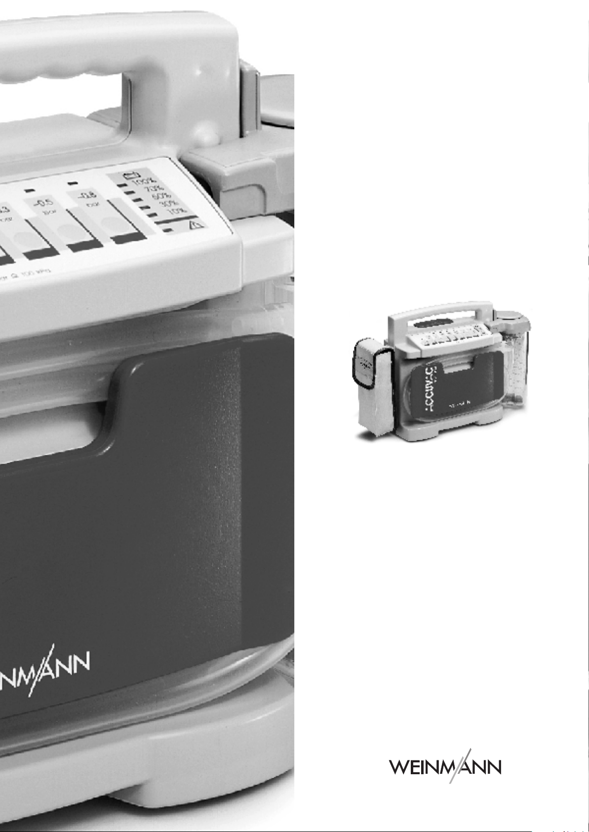
Service and
Repair Instructions
ACCUVAC Rescue
Aspirator
WM 10600
Page 2

Contents
Introduction
1.
Overview
2.
Safety instructions
2.1
Special symbols on the appliance
3.
Description
3.1
Purpose
3.2
Function
4.
Operation
5.
Operating and Display Elements
5.1
Operation
5.2
Service
6.
Maintenance
6.1
Disposal
7.
Function checks
7.1
Intervals
7.2
Performing the function check
8.
Troubleshooting
. . . . . . . . . . . . . . . . . . . . . . . . .
. . . . . . . . . . . . . . . . . . . . . . . . . . .
. . . . . . . . . . . . . . . . . . . . .
. . . . . . . . . . . . . . . . . . . . . . . . . .
. . . . . . . . . . . . . . . . . . . . . . . .
. . . . . . . . . . . . . . . . . . . . . . . .
. . . . . . . . . . . . . . . . . . . . . . . . . .
. . . . . . . . . . . . . . . . . . . . . .
. . . . . . . . . . . . . . . . . . . . . . . .
. . . . . . . . . . . . . . . . . . . . . . . . .
. . . . . . . . . . . . . . . . . . . . . . . .
. . . . . . . . . . . . . . . . . . . . . . .
. . . . . . . . . . . . . . . . . . . . . . . .
. . . . . . . . . . . . . . . . . . . . .
. . . . . . .
. . . . . . . . . .
. . . . . . . . .
10
12
3
4
5
5
6
6
6
7
8
8
8
9
9
9
9
9.
Repairs: Information and Instructions
9.1
General
9.2
Opening the device
9.3
Closing the device
9.4
Replacing release catch
9.5
Replacing membrane keyboard
9.6
Changing the power pack
9.7
Initializing the power pack
9.8
Changing fuse F1 or F2
9.9
Checking connector between circuit
board and power pack
9.10
9.11
9.12
9.13
9.14
10.
Spare Parts
10.1
11.
Tools and Test Equipment
12.
Technical Changes
13.
Technical Data
13.1
14.
Repair and Test Report
. . . . . . . . . . . . . . . . . . . . . .
. . . . . . . . . . . . . .
. . . . . . . . . . . . . . .
Fitting new circuit board WM 10680
Fitting new pump
Changing fuse in vehicle plug
Changing the muffler
Electrical circuit diagram
. . . . . . . . . . . . . . . . . . . . . . . . .
Spare parts list
Safe distances
. . . . . . . . . . . . . . .
. . . . . . . . . . . . .
. . . . . . . . . . . . . . . . .
. . . . . . . . . . . . . .
. . . . . . . . . . . . . . . . . . .
. . . . . . . . . . . . . . . . . . . . . .
. . . . . . . . . . . . . . . . .
. . . . . . . . . . . . . . . .
. . . . . .
. . . . . . . . . . .
. . . . . .
. . . . . . . . . .
. . . . . . . . . .
. . . . . . . . . . .
. . . . . . . . . . . .
. .
. . . . . . .
. . . . . . . . . .
15
15
15
16
16
17
19
20
21
21
22
24
25
25
26
27
27
29
29
30
31
32
© Copyright Weinmann GmbH & Co. KG.
The content and presentation are copyright protected and may only be used by authorised Weinmann Service Partners in the
course of their service operations. The content must not be reproduced or passed on to third parties. The complete documents
must be returned on termination of the cooperation with Weinmann.
2
Page 3

Introduction
For decades Weinmann has been developing,
manufacturing and marketing appliances for emer
gency medical treatment,
inhalation
In 1986 Weinmann launched the first
aspirator on the market.
The improved
provides users with an appliance that is an
indispens
situations. The
to clear the airways, as when preparing for intuba
tion, for example, but also for removing
material.
In stable positioning of injured patients the
ACCUVAC Rescue
flating vacuum mattresses and inflatable splints.
Using the
user more time to look after the patient and perform
other measures.
The purpose of these Service and Repair Instruc
tions is to make sure you as an
familiar with the
functionality and technology and how to repair it.
Combined with training you have already re
therapy.
ACCUVAC Rescue
able aid in many emergency health care
ACCUVAC Rescue
ACCUVAC Rescue
ACCUVAC Rescue
oxygen therapy and
ACCUVAC
aspirator
is used not only
vomited
aspirator can be used for de
aspirator gives the
expert specialist
aspirator: its
are
-
-
ceived
from Weinmann, this makes you a member
-
-
-
of the “authorized expert personnel”
which means you can give your customers proper
instruction, remedy faults independently,
the final checks specified in the Operating Instruc
tions,
and carry out any repairs in accordance with
these Service and Repair Instructions.
In the event of a warranty claim the
aspirator is to be sent to Weinmann
So that we can process warranty claims or requests for generous treatment of complaints,
please send the purchase receipt (invoice) with the
appliance.
Repairs may only be carried out by Weinmann or
by expert personnel.
You are responsible for any repairs you make and for
the relevant warranty!
Only original Weinmann spare parts must be used
for repairs.
Please remember:
Your customer trusts you and relies on your quality,
just as you rely on Weinmann.
category,
perform
-
ACCUVAC Rescue
.
Note:
For the following information, please consult the
ACCUVAC Rescue Operating Instructions:
• Safety information
• Assembly with wall bracket,
Fitting accessories
• Operation
• Hygienic preparation
• Warranty
Introduction
3
Page 4
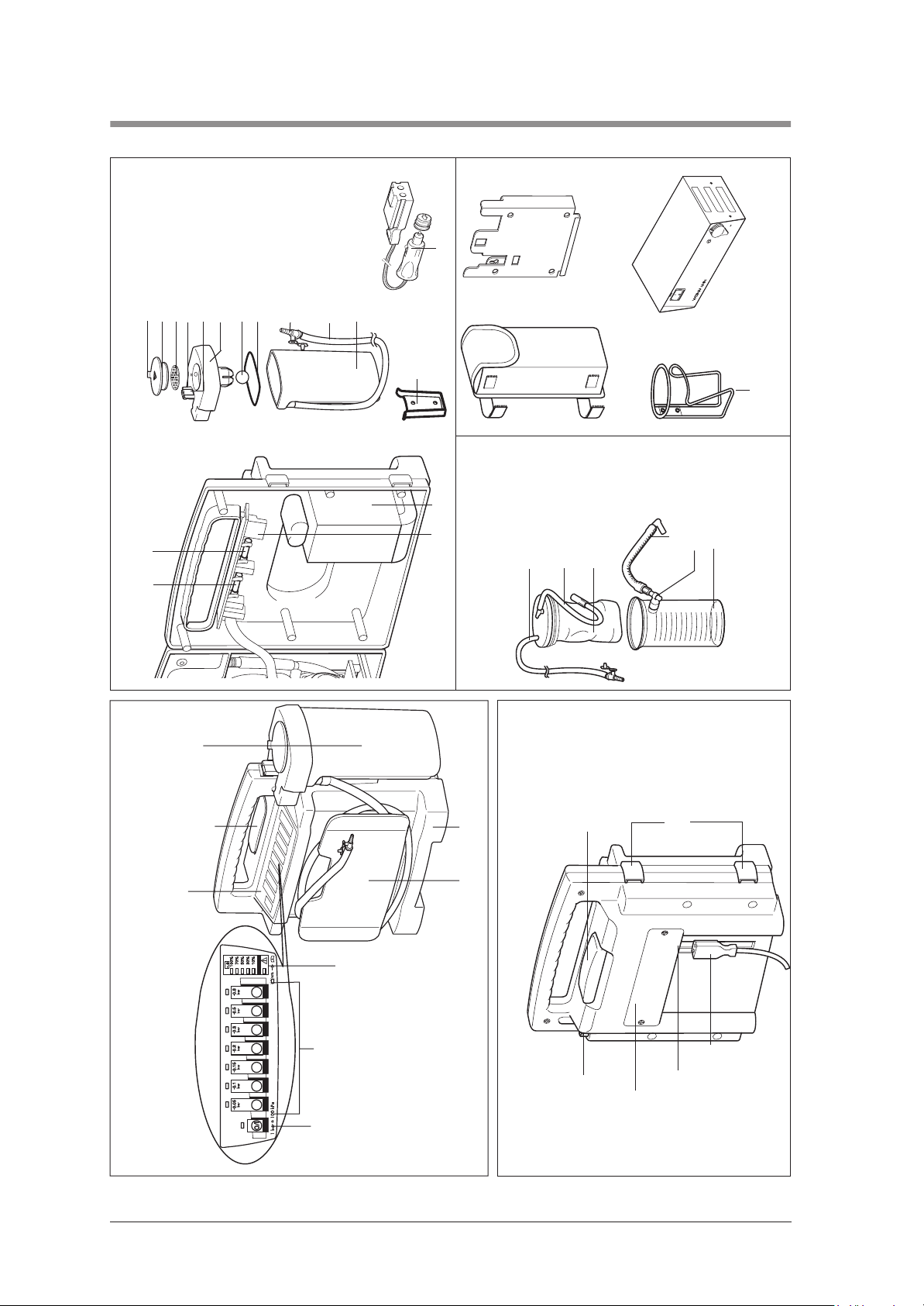
1. Overview
13,8 V
Wall bracket
WM 15208
fingertip
18 Vent tab
19 Filter cover
20 Bacteria filter
21 Locking tab
23 Secretion cover
24 Ball (overfill guard)
22 Bracing clip
25 Sealing ring
26 Nozzle with
27 Aspiration tube
Re-usable collection canister
14 Fuse F1 15 Fuse F2
ACCUVAC Rescue - interior
28 Collection canister
29 Support
10 Connection cable
17 Plug X3 16 Power pack
Accessories
30 Disposable bag container WM 15268
Accessory bag
nozzle and fingertip
31 Aspiration tube with
33 Disposable bag
32 Intermediate tube
WM 10655
34 Vacuum tube
36 Collection
35 T-piece
canister
Mains/charger unit
WM 2645
WM 15172
37 Holder set
ACCUVAC Rescue from front with
disposable collection canister
4 Overview
tion canister
6 Re-usable collec-
5 Release catch
4 Membrane keyboard
3 Capacity indicator
2 Vacuum control
switch
1 On/Off
7 Motor unit
8 Tube holder plate
ACCUVAC Rescue from rear without collection canister
5 Release catch
12 Muffler
13 Suction port
(hidden)
11 Power socket
9 Loops for
(hidden)
accessory bag
10 Connection cable
Page 5
2. Safety instructions
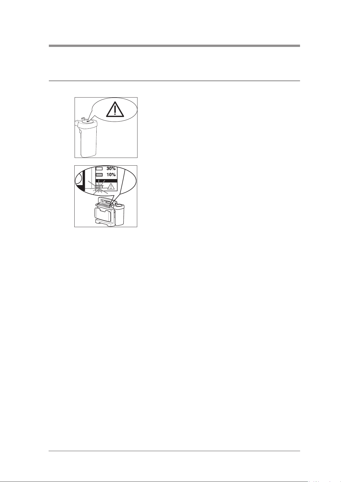
2.1 Special symbols on the appliance
The symbol on the filter cover 19 draws attention to
the built-in bacteria filter 20. This must be changed
or sterilized after use to prevent the risk of infection
(see “5. Cleaning and disinfecting” in the operation manual).
The warning symbol in the capacity indicator 3
draws attention to the risk of complete discharging,
which could damage the power pack 16. If the
10% LED lights up, it is time to recharge the
ACCUVAC Rescue immediately (see “4.4 Charging the ACCUVAC Rescue” in the operation
manual).
Safety instructions 5
Page 6
3. Description
3.1 Purpose
ACCUVAC Rescue is a mobile and portable electrically powered aspirator (suction pump).
It is used for:
• aspirating accumulations of blood, secretions
and food from the oral cavity, the nose and
throat region and the bronchial system;
• deflating vacuum mattresses and inflatable
splints.
ACCUVAC Rescue:
• can when used by a skilled operator eliminate
obstruction of the respiratory tract and hence
the risk of respiratory failure;
• cuts energy consumption by reducing power
output on reaching the necessary vacuum;
3.2 Function
An electrically powered diaphragm pump generates the vacuum necessary for aspiration.
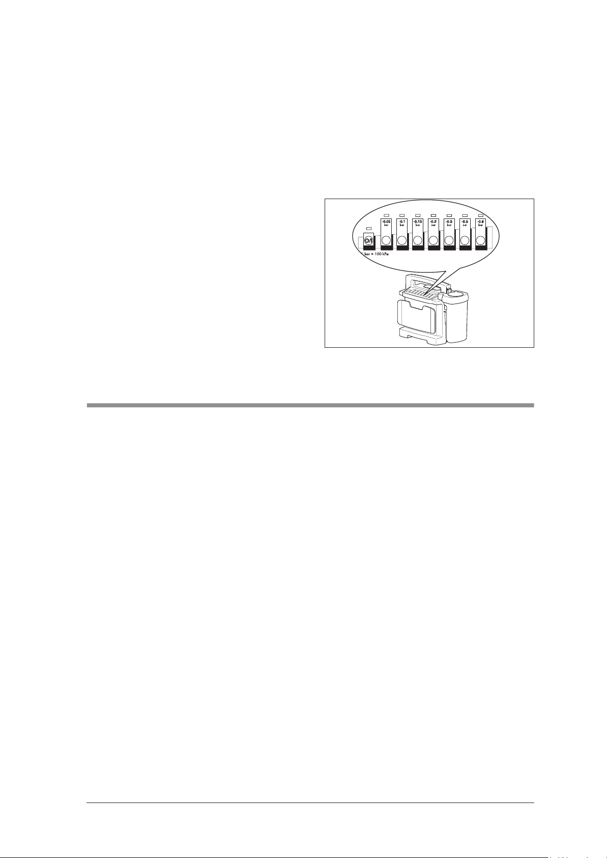
Use the vacuum control 2 to preselect the desired
vacuum between –0.05 bar and –0.8 bar. The
membrane keyboard 4 is illuminated so that you
can see the operating status even after dark.
• can optionally be powered
– by a rechargeable internal power pack;
– or by an external DC source supplying
12.0 - 13.8 V;
• is also suitable for use in wards.
The ACCUVAC Rescue must not be used:
• in medical rooms where potential
equalization is necessary
(e.g. heart surgery);
• in explosion-risk areas.
Note
Once the preselected vacuum is reached, the pump
switches to standby. If the vacuum changes, the pump
starts up again to restore the vacuum to the preselected level.
The aspirated material passes through the aspiration tube 27 into the collection canister.
Re-usable collection canister
The re-usable collection canister 6 is fixed to the
side of the motor unit and directly connected to the
suction port 13 of the motor unit 7. There is thus no
need for an intermediate tube.
A replaceable hydrophobic bacteria filter 20 in the
secretion cover 23 prevents bacteria and droplets
of moisture from finding their way into the motor
unit 7 and passing into the environment via the
muffler 12.
The bacteria filter is designed for multiple re-use
and sterilisation.
6 Description
Page 7
Important: Do not immerse the bacteria filter in dis-
infectant liquid, as this adversely affects its hydrophobic properties.
An overfill system prevents secretions from entering
the motor unit. The ball 24 floats on the surface of
the secretion until it blocks the exit.
Power supply
Power can be drawn from:
• the built-in power pack 16.
• a 12-volt vehicle electrical system, using the
connecting cable.
• the mains and charger unit available as an
accessory.
The capacity indicator 3 shows the charge status
of the power pack in percent.
Charging of the power pack starts automatically
as soon as the appliance is switched off and connected to an external power supply (see ”13.
Technical Data“ on page 30).
4. Operation
ACCUVAC Rescue may only be used by trained staff
instructed in aspiration techniques. Incorrect use can
cause serious bodily harm.
Operation is described in the operating
instructions.
Operation 7
Page 8
5. Operating and Display Elements
5.1 Operation
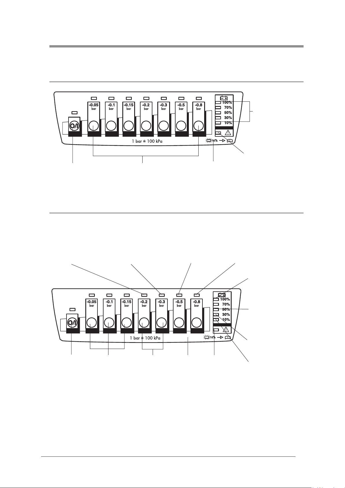
Main switch Keys for desired
suction level
Membrane
keyboard
Capacity
indicator
Adequate external
voltage available
5.2 Service
Bring up service display by pressing keys –0.2 and –0.3 simultaneously.
Charging was
terminated due to
power pack
overvoltage.
Main switch Press
simultaneously
Charging was
terminated due to
incorrect temperature
of power pack.
to initialize
power pack.
Press
simultaneously
for service
display.
Charging was
terminated due to
maximum charging
time being exceeded.
Membrane
keyboard
Adequate
external voltage
available.
Power pack was
discharged down to
discharging limit
voltage.
Charging was
terminated.
A new power pack
was installed. Its
capacity is unknown.
The last charging
operation was
successfully completed.
Initialize power pack
(if LED flashing).
8 Operating and Display Elements
Page 9

6. Maintenance
The ACCUVAC Rescue needs no maintenance,
but please be sure to observe the intervals specified for regular final checks (see ”7.1 Intervals“ on
page 9).
To maintain battery operation and service life we
recommend performing calibration every 8 weeks
according to item 7.1.2 of the description and
6.1 Disposal
Do not dispose of the unit with domestic waste. For proper waste disposal of the equipment, please
contact an approved and certified waste disposal site for electronic goods. Ask your Environmental
Officer or town council for the address.
7. Function checks
operating instructions. This process involves the
necessary specific battery discharging and
recharging.
We recommend that you have any servicing, such
as inspections and repair work, carried out by the
manufacturer – Weinmann – or by expert
personnel.
If the final check reveals defects or deviations from
the specified values, the ACCUVAC Rescue must
not be used again until the faults have been rectified.
7.1 Intervals
To ensure that a properly functioning
ACCUVAC Rescue is always available, it is essential to observe the following intervals.
Before every use
• Perform a function check (see ”7.2 Performing
the function check“ on page 10).
After every use
• Clean, disinfect and/or sterilize the unit and
its parts (see operating instructions “5.
Cleaning and disinfecting”);
• Perform a function check (see ”7.2 Performing
the function check“ on page 10).
Every 6 weeks
• Check the power pack charge level by switching on the ACCUVAC Rescue and reading the
We recommend that you always keep a stock of
the following:
• Aspiration tube 27, WM 10662
• Nozzle with fingertip 26, WM 10666
• Filter 20, WM 10675
capacity indicator. If the capacity is 50% or
less, you should recharge the power pack (see
operating instructions “4.4 Charging the
ACCUVAC Rescue”).
At least every 6 months
• Perform a function check (see ”7.2 Performing
the function check“ on page 10).
• Make a visual inspection of the muffler for
clogging. If it is clogged, fit a new muffler (see
”9.13 Changing the muffler“ on page 25).
After all repairs
• Clean, disinfect and/or sterilize the unit and
its parts (see operating instructions “5. Cleaning and disinfecting”);
• Perform a function check (see ”7.2 Performing
the function check“ on page 10).
Maintenance 9
Page 10
7.2 Performing the function check
1. Assemble ACCUVAC Rescue ready for use.
2. Check that all tubes, the collection canister 28,
secretion cover 23 and filter cover 19 are in
perfect condition. Any damaged and/or worn
parts must be replaced.
4. Switch on the ACCUVAC Rescue.
All LEDs light up for one second after switching
on. After that, only those LEDs that indicate the
operating status stay on. Check the charge
level of the power pack by reading the
capacity indicator 3. If necessary, recharge
the power pack (see operating instructions
“4.4 Charging the ACCUVAC Rescue”).
5. Battery test
A battery test should always be performed
when there are doubts about the performance
of the rechargeable battery, however at the
latest two years after the battery was last
changed.
Procedure:
Charge the ACCUVAC Rescue for 8 hours using the WM 2645 mains charger or for 14
hours using the WM 10750 plug-in power
supply unit. Set a short interval timer to 20 minutes and start the ACCUVAC. After an operating time of 20 minutes the red LED should not
be lit up and the ACCUVAC should be in operation.
If the red LED lights up after 20 minutes, or the
ACCUVAC is no longer working, the battery
is spent and must be replaced. In this case
please replace the battery as described in
section 9.6.
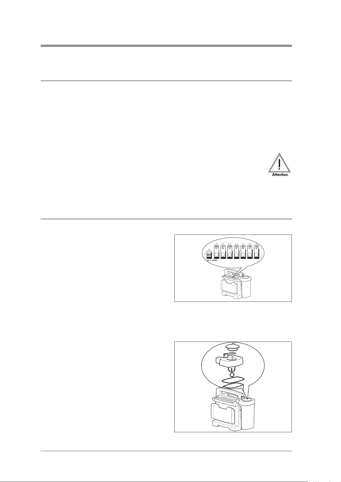
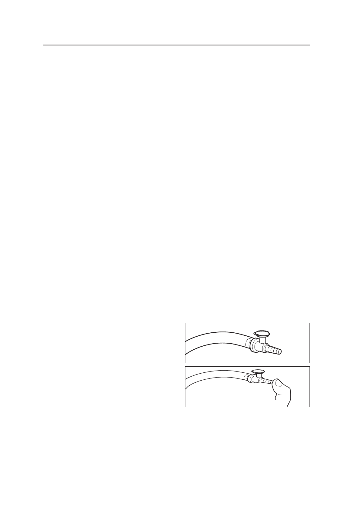
6. Insert the stopper in the fingertip.
3. Check that all tubes are securely connected
and that the secretion cover 23 is firmly in
place.
stopper
7. Use your thumb to hold the nozzle
8. Switch on the aspirator and preselect the maximum vacuum of –0.8 bar. The
ACCUVAC Rescue must reach this vacuum in
not more than 20 seconds. You can tell that
this is the case because the pump stops.
If it takes more than 20 seconds before the
pump stops, the suction capacity is reduced.
Check for possible faults (see ”8. Troubleshooting“ on page 12).
10 Function checks
26 closed.
Page 11

9. Open the suction opening of the nozzle 26.
The aspirator must start running again.
10. Preselect a vacuum of –0.3 bar.
11. Close the end of the nozzle 26 again.
12. As soon as the pump stops, select a vacuum of
–0.2 bar without opening the fingertip.
The vacuum must not fall to –0.2 bar within 10
seconds.
You can tell that the vacuum is falling off by the
fact that the LED above the –0.2 bar button
starts flashing and the pump starts up. This
means there is a leak. In this case check all
tube connections and the re-usable collection
canister 6.
13. Connect the test pressure gage 0 to –1 bar to
the fingertip.
14. Check the accuracy of all suction levels with
the test pressure gage. Start at –0.05 bar. The
tolerance of the individual suction levels must
not exceed +/– 0.04 bar (5% of end value on
scale).
15. Remove the test pressure gage from the fingertip.
-0,4
-0,6
-0,2
-0,8
bar
0
O
2
-1,0
16. Switch off the ACCUVAC Rescue.
Function checks 11
Page 12

8. Troubleshooting
Clear blockage in tube system.
Disconnect external power supply and power
pack from circuit board for at least 2 minutes.
First check the connection between the circuit
board and the front membrane. Otherwise fit
new front membrane.
… fit new circuit board (9.10, page 22)
… fit new pump (9.11, page 24)
Disconnect external power supply and power
pack from circuit board for at least 2 minutes.
Fit new fuse (9.8, page 21)
Perform several charge/discharge cycles. If
unsuccessful, fit new power pack (9.6,
page 19)
Correct polarity and if necessary replace fuse
F1 (9.8, page 21)
Make sure connection snaps in
Detach tube from pressure sensor. Switch
appliance off and on again. Pump must now
run.
Vacuum in system
Controller hanging. Perform reset.
Fault Cause Localize fault Remedy
If display test functions on switching on and the
appropriate set value LED flashes when the
relevant set value key is pressed, the front
membrane is in order. If not, the cause of the
fault may be either the front membrane or the
circuit board.
Connect circuit board to functioning pump and
switch on. If pump does not run, …
Connect pump to functioning circuit board and
Front membrane faulty
Circuit board defective
switch on. If pump does not run, …
Pump defective
If Rescue does not charge up, fuse F1 is
Controller hanging Perform reset
Fuse F1 or F2 in appliance defective
probably defective.
Fuse in vehicle plug defective Fit new fuse (9.12, page 25)
Power pack fully discharged
If an external power supply with incorrect
polarity is connected, a protective diode
ensures that fuse F1 blows to protect the
electronic system.
Incorrect polarity of vehicle power socket
Snap-in connection between circuit board and
power pack not properly engaged
12 Troubleshooting
Appliance does not start. O/I indicator and
capacity indicator show ready for operation
Appliance does not start. O/I indicator does
not show ready for operation
Page 13

Check that all tubes are securely connected and
that filter cover and secretion cover are firmly
installed
Disconnect secretion container from pump unit.
Switch on pump and run at a setting of 0.8 bar.
Hold thumb over suction port. The maximum
vacuum is reached within 5 sec. and the pump
stops. If the pump starts up again within 10 to
… charge power pack (9.6, page 19)
20 sec., the leak is in the pump unit.*
Connect charger WM 2645. If the pump now
runs much more “powerfully” than with the
power pack, you must …
… fit new pump (9.11, page 24)
Connect pump to functioning circuit board and
switch on. If pump does not run …
External power supply must be between 12.0
and 13.8 V.
Allow appliance to cool below +40° C
Check service display (2.1, page 5). If the x-
LED lights up, the external power supply is in
order.
Check service display (2.1, page 5). If the 0.3
bar LED lights up, the power pack temperature
Warm appliance to above +5° C
is not in the operating range 5°C to 45°C
Check service display (2.1, page 5). If the 0.3
bar LED lights up, the power pack temperature
Fit new fuse (9.8, page 21)
is not in the operating range 5°C to 45°C
Check service display (2.1, page 5). If the 0.2
bar LED lights up (power pack overvoltage),
fuse F2 may have blown.
Make sure connection snaps in (9.9, page 21)
Check service display (2.1, page 5). if the 0.2
bar LED lights up (power pack overvoltage), the
connector to the power pack may be loose.
Fault Cause Localize fault Remedy
Leak in suction side of appliance
Power pack not sufficiently charged
Filter clogged Fit new filter (operating instructions 5.3)
Fault in pump
Appliance does not reach maximum vacuum of
–0.8 bar in 20 seconds, but capacity indicator
shows ready for operation
Muffler clogged Fit new muffler (9.13, page 25)
Pump keeps on starting up Leak on suction side of appliance. see above*
External power supply too weak.
Temperature of power pack too high.
No charging possible above +40° C
Temperature of power pack too low.
No charging possible below +5° C
Not charging
Fuse F1 or F2 defective
Fuse in vehicle plug defective Fit new fuse (9.12, page 25)
Snap-in connection between power pack and
circuit board not properly engaged
Troubleshooting 13
Page 14

Initialize (see ”9.7 Initializing the power pack“
on page 20)
Check service display. If the 50% LED lights up,
the software has detected an “unknown” power
pack. This happens when changing the power
pack, fitting a new fuse F2, and sometimes if
power pack is fully discharged, i.e. whenever
the power pack is disconnected from the circuit
board. The software sets the capacity counter to
0% (red LED is on during pumping and
charging) if it detects a power pack voltage of
<10 V during pump operation.
Check vehicle electrical system
… initialize (see ”9.7 Initializing the power
pack“ on page 20)
Check service display (2.1, page 5). If the 30%
LED lights up, the power pack was fully charged
during the last charging operation. Tip: it may
be that the capacity counter is on 99%, with the
result that the 100% LED does not light up.
Switch on pump for approx. 30 sec. and then
charge again. After a few minutes the 100%
LED should light up. If not, the capacity counter
is completely out of adjustment. In that case you
must …
Perform several charge/discharge cycles
(operating instructions 4.4, page 17). If
Charge appliance, switch on and set to 0.8
bar. If the pump power falls off after a few
minutes, the power pack is damaged.
Check service display (2.1, page 5). If the 0.2
unsuccessful, fit new power pack (9.6,
page 19).
bar LED lights up (power pack overvoltage), the
internal resistance of the power pack may be
very high due to age.
Capacity counter cleared.
Charging and aspiration continue to work
Fault Cause Localize fault Remedy
Green 10% LED flashing.
14 Troubleshooting
properly despite this message
Charger does not meet specifications Use mains/charger unit WM 2645
Vehicle electrical system is not supplying 12.0 –
13.8 V
Capacity counter out of adjustment
100% LED does not light up on completion of
charging
Power pack damaged by being fully
discharged
Power pack at end of service life
Page 15

9. Repairs: Information and Instructions
9.1 General
An ESD workplace is essential for making repairs to
the ACCUVAC Rescue.
No work should be performed on the appliance
without a thorough knowledge of the Operating Instructions and the Service and Repair Instructions,
which must always be complied with.
ACCUVAC Rescue is only intended for the purpose described (see ”3.1 Purpose“ on page 6).
9.2 Opening the device
Tools and equipment required:
• Phillips screwdriver size 2.
1. Switch off the ACCUVAC Rescue.
2. Disconnect the aspirator from the external
power supply.
3. Remove the collection canister 28 and any
accessories.
When replacing components or individual parts,
be sure to use only original Weinmann parts.
A function check (see ”7.2 Performing the function
check“ on page 10) must be performed after every
repair.
When ordering the rear part of the case, please
state the appliance type, appliance number and
year of manufacture.
4. Unscrew the holder 29 for the collection
canister.
5. Open the case by unscrewing the 6 crosshead screws 46. When opening the case, be
careful not to damage the silicone sealing
cord.
6. Carefully pull the front and rear case elements
apart.
46
Repairs: Information and Instructions 15
Page 16

9.3 Closing the device
Tools and equipment required:
• Phillips screwdriver size 2
1. Carefully put the front and rear case elements
together again.
2. Screw the case together again, making sure
that the silicone sealing cord is correctly
inserted and is not jammed or otherwise
damaged.
3. Perform a function check (see ”7.2 Performing
the function check“ on page 10).
9.4 Replacing release catch
Tools and equipment required:
46
• Phillips screwdriver size 2;
• Screwdriver, size 1;
• Flat or pointed pliers.
1. Open the device (see ”9.2 Opening the device“ on page 15).
2. Place the ACCUVAC Rescue on its front.
3. Push out retaining pins 63 from release catch
62 and remove them.
4. Remove the old or defective release catch 62.
To do so, use a flat / blunt object to press
down snap lock 65, which is located below
release catch 62.
5. Take the new release catch 62 and insert it in
the rear wall of the case.
6. Take O-ring 64 and locate it in the rear wall of
the case between the loops of the release
catch and the rear wall attachment point.
7. Take the retaining pins 63 and insert them in
the bushing from outside to inside until you
hear them click into place.
62
63
64
8. Close the device (see ”9.3 Closing the device“ on page 16).
9. Perform a function check (see ”7.2 Performing
the function check“ on page 10).
16 Repairs: Information and Instructions
Page 17

9.5 Replacing membrane keyboard
X4
Tools and equipment required:
• Phillips screwdriver size 1;
• 7mm open-end wrench.
1. Open the device (see ”9.2 Opening the device“ on page 15).
2. Carefully detach electrical power pack connector X3 from the circuit board.
3. Unscrew power pack holder (4 cross-head
screws 40).
4. Remove power pack.
40X3
5. Carefully detach electrical connectors X1 and
X2 of internal wiring harness from circuit
board.
6. Carefully detach electrical connector X4 to
motor from circuit board.
7. Carefully detach pressure measurement tube 47
from pressure sensor on circuit board.
8. Carefully open up cable grip of ribbon cable
connector X5. Then carefully remove ribbon
cable (do not touch the ribbon cable contacts
with your fingers, as this can cause oxidation.)
9. Unscrew 4 retaining screws 46 from the circuit
board. Remove the circuit board.
10. Detach the front keyboard 4 from inside
through the front of the case, by pressing the
membrane keyboard out upwards and carefully pulling it off.
X2 X147
X4
X5
46
11. Clean the old adhesive area until no adhesive
residues are left.
12. Take the new membrane keyboard and remove the protective layer from the adhesive
surface. Run the ribbon cable through the
opening in the case front.
Take care when inserting the ribbon cable
through the opening in the housing; it must be
properly routed without any kinks.
13. Stick the new membrane keyboard in the correct position on the case.
Repairs: Information and Instructions 17
Page 18

14. Pull the protective film off the new membrane
40
keyboard.
15. Insert the circuit board again and screw it up
firmly.
16. Carefully restore electrical connections X1, X4
and X5.
X4
X5
X1
46
17. Carefully attach electrical connector X2.
18. Fit tube 47 onto the board again.
19. Insert the power pack again and screw it firmly
in place.
20. Make the electrical connection X3 to the power pack.
21. Close the device (see ”9.3 Closing the device“ on page 16).
22. Perform initialization (see ”9.7 Initializing the
power pack“ on page 20).
23. Perform a function check (see ”7.2 Performing
the function check“ on page 10).
X247
X3
18 Repairs: Information and Instructions
Page 19

9.6 Changing the power pack
The ACCUVAC Rescue is fitted with a high-grade nickel-cadmium power pack.
Tools and equipment required:
• Phillips screwdriver size 2.
1. Open the device (see ”9.2 Opening the device“ on page 15).
2. Carefully disconnect the power pack connector X3 from the circuit board.
3. Unscrew the power pack holder (4 cross-head
screws).
4. Remove the faulty power pack 16.
Help protect the environment!
Don’t throw the old power pack in the garbage can – take it to a local collection point
for environment-friendly disposal.
5. Wait half a minute before fitting the new
power pack. This will allow the capacitors on
the circuit board to discharge.
6. Fit the new power pack with its holder.
7. Carefully push power pack connector X3 onto
the circuit board until it snaps into place.
8. Close the device (see ”9.3 Closing the device“ on page 16).
9. Perform initialization (see ”9.7 Initializing the
power pack“ on page 20).
Note:
The green 10% LED of the capacity indicator 3
continues to flash until the electronic control
system is synchronized with the power pack.
Although the ACCUVAC Rescue will function
when the power pack is charged, the indicator
will not show the charge status of the power pack
unless the system is initialized.
10. Perform a function check (see ”7.2 Performing
the function check“ on page 10).
X3
Repairs: Information and Instructions 19
Page 20

9.7 Initializing the power pack
Initialization matches the capacity indicator 3 to
the energy content of the power pack.
The power pack must be initialized:
• every time a new power pack is fitted;
• every time fuse F2 is changed;
• if the 10 % LED is flashing.
Perform initialization as follows:
1. Charge the ACCUVAC Rescue for about 5
minutes.
2. Disconnect the ACCUVAC Rescue from the external power supply.
3. Press the O/I button to switch on the
ACCUVAC Rescue.
4. Press the following three buttons simultaneously:
-0.05 bar, -0.1 bar, -0.15 bar.
The power pack is now being initialized. All
the LEDs in the capacity indicator strip are
flashing.
5. Press the -0.8 bar button.
The pump now runs at the highest speed and
the power pack discharges until it is completely empty without suffering any damage. Once
the power pack is discharged, the pump stops
automatically. With an empty power pack the
initialization process takes about 5 minutes,
with a full power pack up to 45 minutes.
6. Now connect the ACCUVAC Rescue to an external power supply in order to recharge it.
The charging process takes about 2 hours.
If the pump ran for a long time when discharging because of substantial residual
capacity in the power pack, this may have
heated up the power pack. In this case
charging will not start until the power pack has
cooled down below 40 °C. Depending on
residual capacity this may take up to
45 minutes.
20 Repairs: Information and Instructions
Page 21

9.8 Changing fuse F1 or F2
Important
Never touch the circuit board, as this can damage the
electronic system.
Tools and equipment required:
• Phillips screwdriver size 2.
1. Open the device (see ”9.2 Opening the device“ on page 15).
2. Remove the faulty fuse 14/15. The fuses are
identified on the circuit board.
3. Insert a new fuse. Always use approved fuses
(see ”13. Technical Data“ on page 30).
4. Close the device (see ”9.3 Closing the device“ on page 16).
5. Perform initialization if you have removed fuse
15 (F2) from its holder (see ”9.7 Initializing the
power pack“ on page 20).
6. Perform a function check (see ”7.2 Performing
the function check“ on page 10).
14 15
9.9 Checking connector between circuit board and power pack
Tools and equipment required:
• Phillips screwdriver size 2.
1. Open the device (see ”9.2 Opening the device“ on page 15).
2. Check connector X3.
3. Close the device (see ”9.3 Closing the device“ on page 16).
4. Perform initialization (see ”9.7 Initializing the
power pack“ on page 20).
5. Perform a function check (see ”7.2 Performing
the function check“ on page 10).
X3
Repairs: Information and Instructions 21
Page 22

9.10 Fitting new circuit board WM 10680
40
Important!
For this operation it is essential to use an ESD workplace because of the risk of damage to the circuit
board by static electricity.
Tools and equipment required:
• Phillips screwdriver size 2.
1. Open the device (see ”9.2 Opening the device“ on page 15).
2. Carefully detach electrical power pack connector X3 from the circuit board.
X4
X2 X1
X3
3. Unscrew power pack holder (4 cross-head
screws 40).
4. Remove power pack.
5. Carefully detach electrical connectors X1 and
X2 of internal wiring harness from circuit
board.
6. Carefully detach electrical connector X4 to
motor from circuit board.
7. Carefully detach pressure measurement tube 47
from pressure sensor on circuit board.
X3
X4 X2 X147
22 Repairs: Information and Instructions
Page 23

8. Carefully open up cable grip of ribbon cable
connector X5. Then carefully remove ribbon
cable (do not touch the ribbon cable contacts
with your fingers, as this can cause oxidation.)
9. Unscrew 4 retaining screws 46 from the circuit
board.
10. Insert the new circuit board in reverse order.
Then route connecting cable so it cannot come
into contact with the pump.
• Attention!
Do not connect electrical power pack
connector X3 yet.
• Wait half a minute to allow the capacitors on the
circuit board to discharge.
11. Carefully connect electrical power pack
connector X3.
12. Close the device (see ”9.3 Closing the device“ on page 16).
X3
X4
46
X5
13. Perform initialization (see ”9.7 Initializing the
power pack“ on page 20).
The green 10% LED of the capacity indicator continues flashing until the electronic control system
has been synchronized with the power pack.
Although the fully charged ACCUVAC Rescue can
be used, the power pack charge status is not displayed.
14. Perform a function check (see ”7.2 Performing
the function check“ on page 10).
Repairs: Information and Instructions 23
Page 24

9.11 Fitting new pump
56
The pump is only available as a complete replacement unit.
Tools and equipment required:
• Phillips screwdriver size 2.
1. Open the device (see ”9.2 Opening the device“ on page 15).
2. Carefully detach electrical power pack connector X3 from the circuit board.
3. Open the cable clamp and use a diagonal
cutter to cut through the cable binder. Then remove the motor cable.
4. Remove the O-ring.
X3
5. Unscrew 4 screws 40 from support.
6. Detach silicone fabric tube 57 from inlet port of
pump.
7. Unwind the rolled-up silicone fabric tube 56
from the motor.
8. Detach tube 56 from faulty vacuum pump,
attach it to outlet of new pump 42 and wind it
round motor.
9. Finish fitting the new vacuum pump in reverse
order. To prevent damage, pressure measurement tube 47 must be routed between the inlet
and outlet tubes of the pump.
10. Close the device (see ”9.3 Closing the device“ on page 16).
11. Perform a function check (see ”7.2 Performing
the function check“ on page 10).
47
42
57
40
24 Repairs: Information and Instructions
Page 25

9.12 Changing fuse in vehicle plug
Tools and equipment required:
• Phillips screwdriver size 2.
1. Use a screwdriver to open the vehicle plug.
Note: The central contact of the plug is the plus
pole. The plus lead of the cable has either a
square cross-section or colored markings.
The outer contact of the plug is the minus pole.
The minus lead of the cable is round and
black.
2. Change the faulty fuse 58. Use only approved
fuses (see ”13. Technical Data“ on page 30).
3. Screw the vehicle plug together again.
4. Perform a function check (see ”7.2 Performing
the function check“ on page 10).
9.13 Changing the muffler
Tools and equipment required:
• Phillips screwdriver size 2.
1. Use a screwdriver to unscrew the cover plate
(2 cross-head screws 41).
58
2. Remove the old muffler 12.
3. Insert a new muffler 12.
41
12
Repairs: Information and Instructions 25
Page 26

4. Refit the cover plate 59.
Note that there is a projecting lug on the back
of the cover plate. Be sure to fit the cover plate
so that this lug locates the muffler in position.
5. Perform a function check (see ”7.2 Performing
the function check“ on page 10).
9.14 Electrical circuit diagram
X1
+
red
59
projecting lug
X1
-
black
X2
Power pack, NiCad
Charging/operating contacts
WM 10647
Vacuum pump
WM 10694
Membrane keypad,
Rescue
red
black
X2
X3
X4
X5
Printed circuit board
Accuvac Rescue
WM 10680
26 Repairs: Information and Instructions
Page 27

10. Spare Parts
10.1 Spare parts list
Note:
The item numbers in the following table are identical with the numbers used in these Service and Repair
Instructions and the Operating Instructions.
Item No. Spare Part Order No.
4 Membrane keyboard ACCUVAC Rescue WM 10645
6
19
20
22
23
24
25
26
27
28
8 Tube holder plate, red WM 10623
12 Muffler WM 10665
14 Fuse, external power supply (F1) WM 2692
15 Fuse, power pack (F2) WM 2692
16 NiCad power pack WM 10647
29
30
36
33
31
35
34
Re-usable canister, complete
consisting of:
– Filter cover
– Bacteria filter
– Bracing clip
– Secretion cover
– Ball
– Sealing ring
– Nozzle with fingertip
– Aspiration tube
– Collection canister 900 ml
Holder set for re-usable canister
consisting of:
– Holder
– Fixing elements
Set, disposable bag container, complete
consisting of:
– disposable bag container, complete
– Collection canister
– Disposable bag
– Aspiration tube with nozzle and fingertip
– T-piece
– Vacuum tube
WM 10630
WM 10632
WM 10675
WM 10641
WM 10636
WM 10643
WM 10635
WM 10666
WM 10662
WM 10631
WM 15271
WM 10640
WM 53053
WM 15268
WM 10730
WM 10731
WM 10732
WM 10733
WM 10738
WM 10740
37 Holder set
WM 15172
consisting of:
– Holder
– Fixing elements
38 Front case element, Rescue, assembled, reconditioned* WM 10606
39 Rear case element, Rescue, assembled, reconditioned* WM 10607
40 Oval head screw KB 40x14 WM 23158
41 Countersunk screw KB 40x12 WM 58360
42 Vacuum pump, complete (new)* WM 10694
WM 10735
WM 51091
Spare Parts 27
Page 28

Item No. Spare Part Order No.
43 Vacuum pump, complete (exchange unit)* WM 10605
44 PCB Rescue WM 10680
45 PCB Rescue, exchange unit WM 10604
46 Oval head screw M3x14 WM 53032
47 Pressure measurement tube
WM 10661
consisting of:
– Tube, silicone fabric 3x3; 220 mm long
– Tube nozzle
48 Washer DIN 125 WM 50235
49 Spring washer DIN 127 WM 50350
50 Internal wiring harness, Rescue WM 10686
51 Oval head screw for clip, KB 35x8 WM 58350
52 Washer 4.3 DIN 125 WM 50240
53 Tube, silicone 7x2.5; 690 mm long WM 10668
54
Tube system, internal
WM 10761
WM 10658
WM 10660
consisting of:
55
56
57
58 Fuse, vehicle plug WM 10673
59 Cover plate, red WM 10625
– T reducer 8-4-8
– Tube, silicone fabric 8x3.5; 210 mm long
– Tube, silicone fabric 8x3.5; 70 mm long
WM 10663
WM 10669
WM 10664
60 Round cord 930 mm long WM 10612
61 Cable tie WM 4668
5
Set release catch, red
consisting of:
62
63
64
65
– Release catch, red *
– Retaining pin
– O-ring 2.9 x 1.78
– Snap lock
Tube, silicone fabric 6x3.5; 50 mm long
Tube, silicone fabric 6x3.5; 200 mm long
Operating instructions WM 16136
* When ordering, please state type, appliance no. and year of manufacture
WM 15396
WM 10624
WM 10697
WM 1145/80
WM 10627
WM 10766
WM 10765
28 Spare Parts
Page 29

11. Tools and Test Equipment
Following is a list of tools and test equipment mentioned in these Service and Repair Instructions.
See the relevant chapter for details of the tools and
test equipment needed in each case.
Special tools can be obtained from the
manufacturer, Weinmann.
• Cross-head screwdriver, size 1
• Cross-head screwdriver, size 2
• Pliers
• Vacuum test pressure gage set WM 15294
12. Technical Changes
Technical change From Device No. Date
Reinforced release catch 2117 09.11.98
Software update Version 3.0 4500 22.08.00
New holder for release catch 6730 16.07.01
Case reinforced, use of washers discontinued 8105 20.11.01
Printed circuit board with radio suppression 9145 07.06.02
Vacuum pump without side walls 10048 22.10.02
Appliance plate with e1 mark 13445 28.06.04
Tools and Test Equipment 29
Page 30

13. Technical Data
ACCUV
AC Rescue
Product category according
to 93/42/EEC
Dimensions
WxHxD in mm
Weight approx. 5.1 kg
Canister volume 900 ml
Suction capacity at 12 V
with free flow
Max. vacuum at 12 V 0.8 bar (80 kPa)
Aspiration tube
Hydrophobic bacteria filter
Motor output 50 W
Rated voltage 12 V
Maximum current
consumption
Temperature range
Operation
Charging
Storage
Electromagnetic
compatibility:
Radio interference
suppression
Radio interference resistance
Classification according to EN 60601-1:
Protection against electric shock: class II; with charger: class I
Degree of protection against electric shock: BF
Degree of protection against water: IPX 1 (drip water)
Classification according to
EN ISO 10079-1
II b
370x280x140
> 20 l/min
diam. 10 mm,
length 1300 mm
size rating 1 µm,
water breakthrough
pressure 0.3 bar
3.5 A
–18 °C to +40 °C
+ 5 °C to +40 °C
–40 °C to +70 °C
EN60601-1-2
EN 55011
IEC 1000-4 Parts 2–5 & 11
high vacuum/high flow
ACCUVAC Rescue
Norms complied with
Vehicle plug fuse
Internal fuse F1
external power supply
Internal fuse F2
power pack
Power pack type Nickel cadmium 2.8 Ah
Charging voltage 12.0 to 13.8 V
Operating time after
charging for 2 hours
Operating mode S2 60 min
Service life of power pack
Collection canister APEC
Secretion cover Silicone
Ball PVDF
Filter cover Silicone
Filter holder APEC
EN 60601-1, EN ISO 100791, EN 1789
8 A, DIN 72581,
identification color white
4 A slow-acting,
low breaking capacity
G fuse links 5x20 mm,
conforms to IEC 127
4 A slow-acting,
low breaking capacity
G fuse links 5x20 mm,
conforms to IEC 127
45 min at maximum suction
400 charge/discharge cycles in
approx. 3 years
Materials
From serial no. 13445/2004
(Subject to technical change without notice)
30 Technical Data
Page 31

13.1 Safe distances
The ACCUVAC Rescue is intended for operation in an electromagnetic environment in which high-frequency
interference variables are controlled. The customer or user of the ACCUVAC Rescue can help avoid electromagnetic interference by maintaining the minimum safe distance between portable and mobile high-frequency telecommunication devices (transmitters) and the ACCUVAC Rescue depending on the rated output of the
transmitter as given below.
Recommended safe distances between portable or mobile HF telecommunication
devices (e.g. mobile phones) and the ACCUVAC Rescue
Rated output of
HF device
in W
150 kHz - 80 MHz
d=(3,5/V1) x √√√√P
0.01 0.12 0.12 0.23
0.1 0.37 0.37 0.74
1 1.17 1.17 2.33
10 3.69 3.69 7.38
100 11.67 11.67 23.33
Safe distance depending on transmission frequency
in m
80 MHz - 800 MHz
d=(3,5/V1) x √√√√P
800 MHz – 2,5 GHz
d=(3,5/V1) x √√√√P
Technical Data 31
Page 32

14. Repair and Test Report
Device master data
Keep a record of all tests or repairs performed (please copy attached form for use).
Service performed in
accordance with ACCUVAC-
Service and Repair Instructions
Company
Date Signature
___________ ________________
Company
Date Signature
___________ ________________
Company
Date Signature
___________ ________________
maintenance / repair / comments
Maintenance and repair work carried out in accordance with service document
Company
Date Signature
___________ ________________
32 Repair and Test Report
22525 Hamburg
WM 10600 ACCUVAC Rescue
Manufacturers: Weinmann GmbH + Co.
Device mode: ACCUVAC
WM 10700 ACCUVAC Rescue
Device no.: _______________________
Production date: ___________________
Page 33

Page 34

Page 35

Page 36

WM 16293b - 07/06 · Printed on 100% recycled paper
For decades Weinmann has been
developing, producing and marketing
medical devices for markets around
the world. In cooperation with our
partners we design economic health
systems for diagnosis and therapy in
Sleep Medicine, Home Mechanical
Ventilation, Oxygen Medicine
and Emergency Medicine.
Weinmann
Geräte für Medizin GmbH + Co. KG
P.O. Box 540268 · D-22502 Hamburg
Phone +49/40/5 47 02-0
Fax +49/40/5 47 02-461
E-mail int.sales@weinmann.de
Internet www.weinmann.de
 Loading...