


Weil-McLain Ultra 80, Ultra 105, Ultra 155, Ultra 230, Ultra 299 Manual
...®
Gas-fired water boilers – Series 4
Featuring |
® |
|
|
|
Flexibility |
|
|
Boiler Manual |
ss)NSTALLATION ss-AINTENANCE |
|
|
|
ss3TARTUP ss0ARTS |
®
3ERIES
This manual must only be used by a qualified heating installer/service technician. Read all instructions, including this manual and all other information shipped with the boiler, before installing. Perform steps in the order given. Failure to comply could result in severe personal injury, death or substantial property damage.
Part number 550-100-400/0717
 ® SERIES 4 GAS-FIRED WATER BOILER
Contents
Hazard definitions & Ultra at-a-glance . . . . . . . . . . . . . . 2 Please read before proceeding . . . . . . . . . . . . . . . . . . 4
Prepare boiler location . . . . . . . . . . . . . . . |
. . . . . . . 5 |
||
Prepare boiler . . . . . . . . . . . . . . . . . . . . |
. . . . . . . 7 |
||
Install water piping . . . . . . . . . . . . . . . . . |
. . . . . . . 9 |
||
Using with Weil-McLain AQUA PLUS water heaters . . . . . . |
14 |
||
Venting/air piping — general . . . . . . . . . . . . . . . . . . |
16 |
||
Sidewall vent/air termination: Separate pipes . . . . . . . . . |
20 |
||
DIRECT VENT . . . . . . . . . . . . . . . . . . . . . . . . . |
25 |
||
Install condensate line . . . . . . . . . . . . . . . |
. . . . . . |
27 |
|
Gas piping . . . . . . . . . . . . . . . . . . . . . |
. . . . . . |
29 |
|
Field wiring — basic system . . . . . . . . . . . . |
. . . . . . |
30 |
|
U-Control operation and setup . . . . . . . . . . . |
. . . . . . |
32 |
|
Startup — fill the system . . . . . . . . . . . . . . |
. . . . . . |
35 |
|
Startup — final checks . . . . . . . . . . . . . . . |
. . . . . . |
37 |
|
Check-out/startup verification . . . . . . . . . . . . |
. . . . . . |
42 |
|
The |
Gas-fired water boiler, Featuring |
Flexibility . |
44 |
Prepare boiler — convert for propane . . . . . . . |
. . . . . . |
48 |
|
Placing boiler — wall-mounting option . . . . . . . |
. . . . . . |
50 |
|
Install water piping — advanced . . . . . . . . . . |
. . . . . . |
52 |
|
Direct-connected DHW piping . . . . . . . . . . . |
. . . . . . |
56 |
|
Multiple boiler installations . . . . . . . . . . . . . |
. . . . . . |
58 |
|
Venting/air piping — Massachusetts installations. . |
. . . . . . |
65 |
|
Vent/air piping — options . . . . . . . . . . . . . . |
. . . . . . |
66 |
|
Sidewall vent/air termination: Weil-McLain cap. . . |
. . . . . . |
67 |
|
Sidewall vent/air termination: 3” or 4” concentric . . |
. . . . . . |
72 |
|
Vertical vent/air termination: 3” or 4” concentric . . |
. . . . . . |
75 |
|
Concentric vent/air termination assembly. . . . . . |
. . . . . . |
78 |
|
DIRECT VENT: Vertical vent / sidewall air . . . . . |
. . . . . . |
79 |
|
Install vent/air piping — boiler to termination . . . . |
. . . . . . |
82 |
|
DIRECT EXHAUST venting — general . . . . . . . |
. . . . . . |
83 |
|
DIRECT EXHAUST — Boiler room air openings . . |
. . . . . . |
84 |
|
DIRECT EXHAUST — Sidewall . . . . . . . . . . |
. . . . . . |
86 |
|
DIRECT EXHAUST — Vertical . . . . . . . . . . . |
. . . . . . |
89 |
|
Install vent — from boiler to termination . . . . . . |
. . . . . . |
91 |
|
Gas piping — sizing gas lines . . . . . . . . . . . |
. . . . . . |
93 |
|
Field wiring — advanced . . . . . . . . . . . . . . |
. . . . . . |
94 |
|
U-Control operation and setup — advanced . . . . |
. . . . . . |
99 |
|
Annual startup and general maintenance. . . . . . |
. . . . . . 108 |
||
Annual startup . . . . . . . . . . . . . . . . . . . |
. . . . . . 109 |
||
Troubleshooting . . . . . . . . . . . . . . . . . . . |
. . . . . . 115 |
||
Maintenance . . . . . . . . . . . . . . . . . . . . |
. . . . . . 125 |
||
Replacement parts . . . . . . . . . . . . . . . . . |
. . . . . . 128 |
||
Dimensions . . . . . . . . . . . . . . . . . . . . . |
. . . . . . 136 |
||
Ratings — Ultra Series 4 boilers . . . . . . . . . . . . . . . . 137 Installation and Service Certificate . . . . . . . . . . . . . . . 140
Hazard definitions
The following defined terms are used throughout this manual to bring attention to the presence of hazards of various risk levels or to important information concerning the life of the product.
Indicates presence of hazards that will cause severe personal injury, death or substantial property damage.
Indicates presence of hazards that can cause severe personal injury, death or substantial property damage.
Indicates presence of hazards that will or can cause minor personal injury or property damage.
Indicates special instructions on installation, operation or maintenance that are important but not related to personal injury or property damage.
2
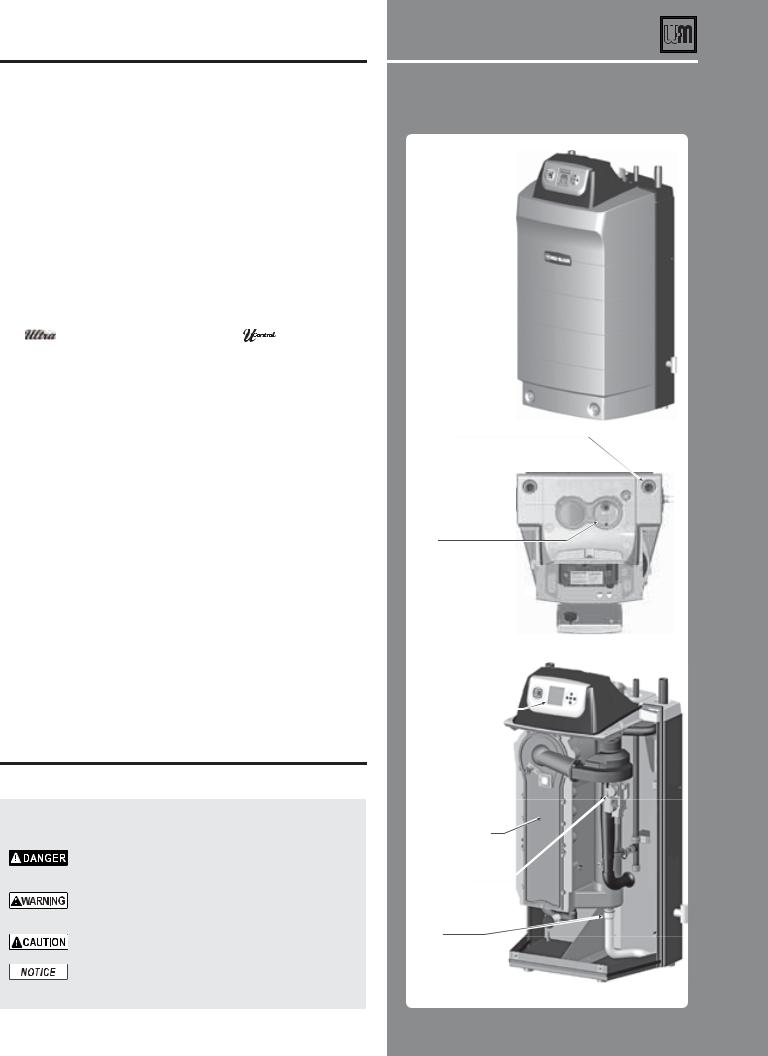
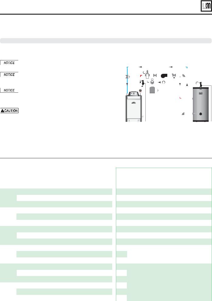
Ultra at-a-glance
(see page 44 and page 46 for details of all models)
'SPOU
'SPOU EPPS 
4VQQMZ
3FUVSO 
"JS JOUBLF  'MVF
'MVF
5PQ
DPOUSPM QBOFM TXVOH PQFO
&MFDUSPOJD EJTQMBZ CVUUPOT
*OUFSJPS
UZQJDBM
"MVNJOVN DPOEFOTJOH IFBU FYDIBOHFS
(BT WBMWF CMPXFS BOE WFOUVSJ
$POEFOTBUF ESBJO
6
Part number 550-100-090/1113

"!3)# ).34!,,!4)/.
Quick view . . .
Pages |
0ROCEDURE |
|
|
4 |
0LEASE READEBEFORERPROCEEDING |
r 3FBE TBGFUZ JOGPSNBUJPO CFGPSF QSPDFFEJOH |
|
|
|
|
0REPAREPBOILER LOCATION |
5–6 |
r $MFBSBODFT ëPPS BOE GPVOEBUJPO |
|
r "JS PQFOJOHT UP SPPN GPS WFOUJMBUJPO |
|
|
|
0REPAREPBOILER |
|
r .BLF TVSF WFOU BJS QJQJOH DBO CF DPOOFDUFE |
7–8 |
r 3FNPWF GSPN DSBUF |
|
r $POWFSU GPS QSPQBOF JG SFRVJSFE |
|
r )ZESPTUBUJD UFTU |
|
r 1MBDF CPJMFS JO QPTJUJPO |
|
|
|
)NSTALLTWATERLPIPING |
9–15 |
r *OTUBMM CPJMFS USJN BOE OFBS CPJMFS QJQJOH |
|
r $PNQMFUF TZTUFN QJQJOH BOE DPOOFDUJPOT |
|
|
|
!PPLIANCES LEFTCON AN EXISTINGTVENT SYSTEM |
16 |
r 'PS BQQMJBODFT SFNBJOJOH PO B WFOU TZTUFN BѫFS PME |
|
CPJMFS JT EJTDPOOFDUFE WFSJGZ UIBU UIF WFOU TZTUFN |
|
XPSLT GPS SFNBJOJOH BQQMJBODFT |
|
6ENT AIR PIPING |
|
r -PDBUFBJSJOUBLFQJQJOHUPQSFWFOUDPOUBNJOBOUTGSPN |
16-26 |
FOUFSJOH CPJMFS |
|
r *OTUBMM WFOU BJS UFSNJOBUJPO |
|
r *OTUBMM WFOU BOE BJS QJQJOH VTJOH BDDFQUBCMF |
|
NBUFSJBMT |
|
)NSTALLTCONDENSATE PIPING |
27–28 |
r $POOFDU DPOEFOTBUF IPTF |
|
r *OTUBMM DPOEFOTBUF QVNQ BOE êMUFS JG SFRVJSFE |
|
|
|
'ASAPIPING |
29 |
r 7FSJGZ HBT QJQF TJ[F |
|
r $POOFDU CPJMFS UP HBT MJOF |
|
|
30-31 |
&IELDEWIRING |
r $POOFDU XJSJOH UP CPJMFS BOE DPNQPOFOUT |
|
|
|
32–34 |
5 #ONTROL OPERATION AND SETUP |
r 6 $POUSPM PQFSBUJPO BOE TFUVQ JOGPSNBUJPO |
|
|
|
|
3TART UP |
|
r $MFBO TZTUFN UIFO êMM BEE JOIJCJUPS |
|
r 7FSJGZ XBUFS DIFNJTUSZ |
35–42 |
r 1VSHF BJS GSPN TZTUFN |
|
r 1FSGPSN êOBM DIFDLT |
|
r 4UBSU BOE PQFSBUF CPJMFS |
|
r 1FSGPSN êOBM WFSJêDBUJPO UFTUT |
|
r 'JMM PVU *OTUBMMBUJPO BOE 4FSWJDF $FSUJêDBUF |
|
|
"!3)# ).34!,,!4)/. |
<![if ! IE]> <![endif]>.34!,,!4)/.) |
|
conventional systems and to sidewall vent/air |
||
0AGES n |
|
|
This section covers basic installation and |
|
|
start-up for most applications. It is limited to |
<![if ! IE]> <![endif]>"!3)# |
|
piping using the Weil-McLain termination cap. |
||
|
||
For applications not covered in this section, |
|
|
see the ADVANCED INSTALLATION section. |
|
|
|
|
!$6!.#%$#).34!,,!4)/.
0AGES n
Read and follow the instructions in the BASIC INSTALLATION section first. Then use the ADVANCED section for additional information.
This section covers multiple boiler systems and additional system types not covered under the BASIC section. It also includes alternative vent/air piping methods, water and gas pipe sizing guidelines and advanced, detailed information on the U-Control.
-!).4%.!.#%% .
30%#)&)#!4)/.3/
0AGES n
This section covers maintenance requirements for all boilers, repair parts lists, boiler dimensions and speci fications.
Part number 550-100-090/1113 |
3 |
 ® SERIES 4 GAS-FIRED WATER BOILER — Boiler Manual
Please read before proceeding
)NSTALLER— Read all instructions, including this manual and all other information shipped with the boiler, before installing. Perform steps in the order given.
5SER — This manual is for use only by a qualified heating installer/service technician. Refer to User’s Information Manual for your reference.
5SER — Have this boiler serviced/inspected by a qualified service technician, at least annually.
Failure to comply with the above could result in severe personal injury, death or substantial property damage.
If any part of a boiler, burner or its controls has been sprayed with or submerged under water, either partially or fully, DO NOT attempt to operate the boiler until the boiler has been either replaced or completely repaired, inspected, and you are sure that the boiler and all components are in good condition and fully reliable.
Otherwise, by operating this boiler, you will cause a fire or explosion hazard, and an electrical shock hazard, leading to serious injury, death, or substantial property damage. See the instructions at right.
Write in the CP number in the space provided on the Installation certificate on page 140 if not already shown.
When calling or writing about the boiler— Please have the boiler model number from the boiler rating label and the CP number from the boiler jacket.
Consider piping and installation when determining boiler location.
Any claims for damage or shortage in shipment must be filed immediately against the transportation company by the consignee.
3ALTWATERW$AMAGE — The exposure of boiler components to saltwater can have both immediate and long-term effects.While the immediate effects of saltwater damage are similar to those of freshwater (shorting out of electrical components,washing out of critical lubricants,etc.),the salt and other contaminants left behind can lead to longer term issues after the water is gone due to the conductive and corrosive nature of the salt residue. Therefore, Weil-McLain equipment contaminated with saltwater or polluted water will no longer be covered under warranty and should be replaced.
%LECTRICAL $AMAGE — If any ELECTRICAL COMPONENT or WIRING came into contact with water, or was suspected to have come into contact with water,replace the boiler with a new Weil-McLain boiler.
Failure to adhere to the guidelines below can result in severe personal injury, death or substantial property damage.
When servicing boiler —
ssTo avoid electric shock, disconnect all electrical supplies to the boiler before performing maintenance.
ssTo avoid severe burns, allow boiler to cool before performing maintenance.
ssThis boiler contains ceramic fiber and fiberglass materials. Refer to the WARNING and instructions on page 109.
"OILER OPERATION
ssDo not block flow of combustion or ventilation air to boiler.
ssShould overheating occur or gas supply fail to shut off, do not turn off or disconnect electrical supply to pump. Instead, shut off the gas supply at a location external to the appliance.
#OMBUSTION AIR
ssDO NOT install combustion air intake where there is a risk of combustion air contamination.
#ARBON MONOXIDE DETECTORE
ssA carbon monoxide detector that is wired on the same electrical circuit as the boiler is strongly recommended.
352'%202/4%#4/2
ssProvide surge protection in the boiler power supply. This will reduce the possibility of damage to the boiler control.
Boiler water —
ssThe Ultra heat exchanger is made of aluminum, and requires that system pH always be between 7.0 and 8.5 and water chemistry be checked. Chemical treat-
ment may be necessary. !$$)4)/.!,
#(%-)#!,42%!4-%.4%-!99"%.%#%3 3!29. See page 35 for details.
ssThoroughly flush the system ("%&/2% connecting boiler) to remove sediment. The high-efficiency heat exchanger can be damaged by build-up or corrosion due to sediment.
ssDo not use petroleum-based cleaning or sealing compounds in boiler system. Gaskets and seals in the system may be damaged. This can result in substantial property damage.
ssContinual fresh make-up water will reduce boiler life. Mineral buildup in eat exchanger reduces heat transfer, overheats the aluminum heat exchanger, and causes failure. Addition of oxygen carried in by make-up water can cause internal corrosion. Leaks in boiler or piping must be repaired at once to prevent make-up water. Use this boiler ONLY in a closed-loop system.
ssDo not add cold water to a hot boiler. Thermal shock can cause heat exchanger to crack.
Freeze protection fluids —
ssNEVER use automotive or standard glycol antifreeze. Use only freeze-protec- tion fluids made for hydronic systems. Use only freeze-protection fluids recommended in this manual (see page 35). Follow all guidelines given by the antifreeze manufacturer. Thoroughly clean and flush any replacement boiler system that has used glycol before installing the new Ultra boiler
Frozen Water Damage
Hazard
Residences or buildings that are unattended in severely cold weather, boiler system components failures, power outages, or other electrical system failures could result in frozen plumbing and water damage in a matter of hours. For your protection, take preventative actions such as having a security system installed that operates during power outages, senses low temperature, and initiates an effective action. Consult with your boiler contractor or a home security agency.
Commonwealth of
Massachusetts
4
When the boiler is installed within the Commonwealth of Massachusetts: ss This product must be installed by a licensed plumber or gas fitter.
ss If antifreeze is used, a reduced pressure back-flow preventer device shall be used. ss Sidewall vent air installations — see instruction on page 65.
Part number 550-100-400/0717

 ® SERIES 4 GAS-FIRED WATER BOILER — Boiler Manual
Prepare boiler location
Installations must comply with:
ssLocal, state, provincial, and national codes, laws, regulations and ordinances.
ss National Fuel Gas Code, ANSI Z223.1 /NFPA 54 – latest edition.
ssStandard for Controls and Safety Devices for Automatically Fired Boilers, ANSI/ASME CSD-1, when required.
ss National Electrical Code.
ssFor Canada only: Natural Gas and Propane Installation Natural Gas and Propane Installation CAN/CSA B149.1 or B149.2 Installation Code, CSA C22.1 Canadian Electrical Code Part 1 and any local codes.
The Ultra boiler gas manifold and controls met safe lighting and other performance criteria when boiler underwent tests specified in ANSI Z21.13 — latest edition.
Before locating the boiler, check:
1. Check for nearby connection to: ss System water piping
ss Venting connections ss Gas supply piping
ss Electrical power
ss Condensate drain
2.Check area around boiler. Remove any combustible materials, gasoline and other flammable liquids.
Failure to keep boiler area clear and free of combustible materials, gasoline and other flammable liquids and vapors can result in severe personal injury, death or substantial property damage.
3.The Ultra boiler must be installed so that gas control system components are protected from dripping or spraying water or rain during operation or service.
4.If new boiler will replace existing boiler, check for and correct system problems, such as:
ssSystem leaks causing oxygen corrosion or heat exchanger cracks from hard water deposits.
ss Incorrectly-sized expansion tank.
ssLack of freeze protection in boiler water causing system and boiler to freeze and leak.
&IGURE Clearances required
$LU YHQWLODWLRQ RSHQLQJV ZKHQ UHTXLUHG ² VHH ³3URYLGH DLU RSHQLQJV WR URRP´
PD[LPXP EHORZ FHLOLQJ RI HQFORVXUH
PD[LPXP DERYH IORRU RI HQFORVXUH
$LU YHQWLODWLRQ RSHQLQJVVHH LQVWUXFWLRQV LQ WKLV PDQXDO
8
)/8( 3,3( &RPEXVWLEOH VXUIDFHV ²´ PLQ ² 2SHQLQJ LQ FRPEXVWLEOH ZDOO IORRU FHLOLQJ RU URRIODUJHU WKDQ IOXH SLSH GLDPHWHU ILWWHG ZLWK JDOYDQL]HG VWHHO WKLPEOH
723  6HUYLFH ²
 PLQ
PLQ
&RPEXVWLEOH VXUIDFHV ² ò PLQ
5LJKW 6,'( 6HUYLFH RU FRPEXVWLEOH VXUIDFHV ²PLQ
/HIW 6,'( 6HUYLFH ²PLQ &RPEXVWLEOH VXUIDFHV ² ò PLQ
%27720 6HUYLFH ²  PLQ
PLQ
&RPEXVWLEOH VXUIDFHV ²PLQ
)5217 6HUYLFH ²PLQ
&RPEXVWLEOH VXUIDFHV ² ò PLQ
Clearances for service access
1.See Figure 1 for recommended service clearances. If you do not provide minimum clearances shown, it might not be possible to service the boiler without removing it from the space.
Provide clearances:
Clearances from combustible materials
1.Hot water pipes — at least ½” from combustible materials.
2.Vent pipe — at least 3/16” from combustible materials.
3.See Figure 1 for other clearance minimums.
Wall mounting option
1.Ultra boilers can be wall mounted (using special wall mount kit) or floor mounted. .O CLEARANCE IS RE QUIRED AT THEHREAR OF THEHUNIT, either for service or for clearance to combustible surfaces.
2.Boilers can be wall mounted ONLY if using the optional wall-mount kit available from Weil-McLain. See page 50 for instructions.
Part number 550-100-400/0717 |
5 |
<![endif]>"!3)# ).34!,,!4)/.
 ® SERIES 4 GAS-FIRED WATER BOILER — Boiler Manual
Prepare boiler location (continued)
Flooring and foundation |
Provide air openings to room |
Flooring
1.The Ultra boiler is approved for installation on combustible flooring, but must never be installed on carpeting.
Do not install boiler on carpeting even if foundation is used. Fire can result, causing severe personal injury, death or substantial property damage.
Foundation
1.Provide a solid foundation pad, at least 2 inches above the floor, if any of the following is true:
ss floor can become flooded.
ss the floor is dirt, sand, gravel or other loose material.
ssthe boiler mounting area is severely uneven or sloped.
2.The minimum foundation size is:
ssUltra-80 to -230: 24 inches wide x 20 inches deep.
ss Ultra-299/310 to -399: 24 inches wide x 23 inches deep.
3.Foundation may be of wood, brick or concrete (minimum 2 inches thick) construction.
4.If flooding is possible, elevate boiler sufficiently to prevent water from reaching boiler.
Residential garage installation
Precautions
1.Take the following special precautions when installing the boiler in a residential garage. If the boiler is located in a residential garage:
ssMount the boiler at a height above the floor as specified in the National Fuel Gas Code, ANSI Z223.1 NFPA 54 for U. S. installations, or Natural Gas and Propane Installation CAN/ CSA B149.1 and B149.2 for Canadian installations.
ssLocate or protect the boiler so it cannot be damaged by a moving vehicle.
ssEnsure that the installation complies with all applicable codes.
Air openings — Ultra boiler alone in boiler room
1.No air ventilation openings into boiler room are needed when clearances around Ultra boiler are at least equal to the SERVICE clearances shown in Figure 1, page 5.
2.For spaces that do NOT supply this clearance, provide two openings as shown in Figure 1, page 5. Each opening must provide 1 square inch free area per 1,000 Btuh of boiler input.
Air openings — Ultra boiler in same space with other gas or oil-fired appliances
1.Follow the National Fuel Gas Code (U. S.) or Natural Gas and Propane Installation CAN/CSA B149.1 and B149.2 (Canada) to size/verify size of the combustion/ ventilation air openings into the space.
The space must be provided with combustion/ventilation air openings correctly sized for all other appliances located in the same space as the Ultra boiler.
Reinstall boiler jacket front door after servicing. The boiler front door must be securely fastened to the boiler to prevent boiler from drawing air from inside the boiler room. This is particularly important if the boiler is located in the same room as other appliances.
Failure to comply with the above warnings could result in severe personal injury, death or substantial property damage.
2.Size openings only on the basis of the other appliances in the space. No additional air opening free area is needed for the Ultra boiler because it takes its combustion air from outside (direct vent installation).
6 |
Part number 550-100-400/0717 |

 ® SERIES 4 GAS-FIRED WATER BOILER — Boiler Manual
Prepare boiler
Vent and air piping (page 16)
1.The Ultra boiler requires a special vent system, designed for pressurized venting. Ultra boilers are rated ANSI Z21.13 Category IV (pressurized vent, likely to condense in the vent). See instructions beginning on page 16.
2.You must also install air piping from outside to the boiler air intake adapter. The resultant installation is categorized as direct vent (sealed combustion). Note prevention of combustion air contamination on page 16 when considering vent/air termination.
3.Vent and air must terminate near one another and may be vented vertically through the roof or out a side wall. You may use any of the vent/air piping methods covered in this manual. Do not attempt to install the Ultra boiler using any other means.
4.Be sure to locate the boiler such that the vent and air piping can be routed through the building and properly terminated. The vent/air piping lengths, routing and termination method must all comply with the methods and limits in instructions beginning on page 16.
Prepare boiler for propane (when required)
Propane operation
5LTRATBOILERSSMUSTSBE CONVERTED FOR PROPANEAOPERATIONAUNLESS SPE CIlCALLYYMANUFACTUREDTFOR PROPANE. Propane-ready boilers have suffix “LP” after the model number. All other boilers require conversion for propane operation.
Refer to propane conversion instructions beginning on page 48.
Failure to comply could result in severe personal injury, death or substantial property damage.
Remove boiler from crate
Cold weather handling — If boiler has been stored in a very cold location (below 0°F) before installation, handle with care until the plastic components come to room temperature.
1.The Ultra boiler is generally easier to handle and maneuver after removing from crate.
2.After removing outer shipping carton from boiler, REMOVE jacket front door by loosening two (2) screws at lower front. Removing the door will prevent possible damage to the door during handling.
3.To remove boiler from pallet (after removing jacket front door):
a.Remove the lag screws securing the shipping brackets.
b.Unscrew the two rear boiler legs and remove the shipping brackets.
c.Replace legs.
d.Discard the cardboard protector insert on the rear of the boiler.
Do not drop boiler or bump jacket on floor or pallet. Damage to boiler can result.
Placing floor-mounted boilers
1.Set boiler in place and check level.
a. Adjust legs, if necessary to level boiler.
Wall-mounted boilers
1.Boilers can be wall mounted ONLY if using the optional wall-mount kit available from Weil-McLain. See page 50 for instructions.
Part number 550-100-400/0717 |
7 |
<![endif]>"!3)# ).34!,,!4)/.
 ® SERIES 4 GAS-FIRED WATER BOILER — Boiler Manual
Prepare boiler (continued)
$/ ./44INSTALLTAARELIEF VALVE WITH AAPRESSURE HIGHER THAN 03)'. This is the maximum allowable relief valve setting for the Ultra boiler.
Perform hydrostatic pressure test
Pressure test boiler before permanently attaching water or gas piping or electrical supply.
Prepare boiler for test
1.See Figure 2 for reference in following steps.
2.Remove supply line tees* and 3/4” elbow from accessory bag. Pipe to boiler supply connection as shown. Use pipe dope sparingly. (* 1”x1”x1/4” and *1”x1”x3/4” tees with Ultra-80 to -230 or * 1-1/4”x1-1/4”x1/4” and *1-1/4”x1-1/4”x3/4” tees with Ultra 299/310/399.
3.Temporarily plug the ¾” relief valve tapping in the street elbow with a ¾” NPT pipe plug.
4.Connect a hose to the boiler drain valve, the other end connected to a fresh water supply. Make sure the hose can also be used to drain the boiler after test.
5.Connect a nipple and shutoff valve to system supply connection on the supply tee. This valve will be used to bleed air during the fill. (Valve and nipple are not included with boiler.)
6.Connect a shutoff valve to system return connection. (Valve is not included with boiler.)
7.To avoid getting water on boiler, you may want to pipe street elbows on top of shutoff valves and attach catch-buckets beneath.
8.If convenient, install the boiler circulator and any other piping compatible with Figure 2 that would still allow bleeding air from shutoff valves.
9.Follow guidelines in this manual for piping components, locations and sizing.
Fill and pressure test
1.Open the shutoff valves you installed on supply and return connections.
2.Slowly open boiler drain valve and fresh water supply to fill boiler with water. The boiler will fill quickly because of its low water content.
3.When water reaches shutoff valves, close boiler drain valve.
4.Close shutoff valves.
5.Slowly reopen boiler drain valve until test pressure on the pressure/temperature gauge reaches at least 45 psig, but no higher than 55 psig.
6.Hold at test pressure for 10 minutes.
Do not leave boiler unattended. A cold water fill could expand and cause excessive pressure, resulting in severe personal injury, death or substantial property damage.
7.Make sure constant gauge pressure has been maintained throughout test. Check for leaks. Repair if found.
,EAKSAMUSTSBE REPAIREDRAT ONCE Failure to do so can damage boiler, resulting in substantial property damage.
8
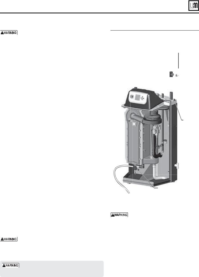
&IGURE Hydrostatic test piping connections
3FNPWF Ñ QMVH GSPN TUSFFU FMCPX BOE JOTUBMM SFMJFG WBMWF BGUFS IZESPTUBUJD UFTUJOH JT DPNQMFUFE 'PMMPX JOTUSVDUJPOT JO UIJT NBOVBM
5FNQPSBSZ TIVU PGG WBMWF PO CPJMFS TVQQMZ
|
/JQQMF PS |
|
|
|
/15 |
Ñ QMVH |
|
|
Y YÑ PS |
SFNPWF BGUFS |
|
|
UFTUJOH |
||
|
Y YÑ UFF |
||
|
|
||
|
TVQQMJFE XJUI |
Ñ TUSFFU |
|
|
CPJMFS MPPTF |
||
5FNQPSBSZ |
/JQQMF PS |
FMCPX TVQQMJFE |
|
XJUI CPJMFS MPPTF |
|||
TIVU PGG WBMWF PO |
/15 |
||
|
|||
CPJMFS SFUVSO |
|
Y Y PS |
|
|
|
Y Y UFF |
|
|
|
TVQQMJFE XJUI |
|
|
|
CPJMFS MPPTF |
|
|
|
1SFTT 5FNQFS |
|
|
|
HBVHF TVQQMJFE |
|
|
|
XJUI CPJMFS MPPTF |
|
|
|
4VQQMZ QJQF |
|
|
|
/15 PO |
|
|
|
6MUSB UP |
|
|
|
6MUSB |
|
|
|
/15 PO |
|
|
|
6MUSB |
6
%SBJO WBMWF
$POOFDU IPTF GSPN CPJMFS ESBJO WBMWF UP GSFTI XBUFS TVQQMZ
Do not use petroleum-based cleaning or sealing compounds in boiler system. Gaskets and seals in the system may be damaged. This can result in substantial property damage.
Drain and remove fittings
1.Disconnect fill water hose from water source.
2.Drain boiler through drain valve. Remove hose after draining.
3.Remove nipples and valves unless they will remain for use in the system piping.
4.Remove plug from relief valve street elbow. See page 9 to install relief valve.
Part number 550-100-400/0717
 ® SERIES 4 GAS-FIRED WATER BOILER — Boiler Manual
Install water piping
Use two wrenches when tightening water piping at boiler, using one of the wrenches to prevent the boiler interior piping from turning. Failure to support the boiler piping connections to prevent them from turning could cause damage to boiler components.
General piping information
Additional controls, when required
The U-Control module uses temperature sensors to provide both high limit protection and modulating temperature control. The U-Control module also provides low water protection by sensing the temperature of the heat exchanger. Some codes/jurisdictions may require additional external controls for high limit and/or low water cutoff protection.
Additional limit controls
Following standard industry practices, if installation is to comply with ASME or Canadian requirements, an additional high temperature limit may be needed. Consult local requirements for other codes/standards to determine if needed.
1.Install a manual reset high temperature limit constructed to prevent a temperature setting above 200°F in system supply piping between boiler and isolation valve. (Note that the U-Control module operating limit function shuts the boiler down at 195°F, or lower if set to a lower value.)
-ULTI TEMPERATUREMSYSTEMS — If the heating system includes circuits that require lower temperature water (radiant slab circuits, for example) as well as higher temperature circuits, it is recommended to protect lowtemperature circuits with limit controls that are wired to a U-Control external limit circuit (P13 terminals 1 and 2 for manual reset, or P13 terminals 3 and 4 for automatic reset).
2.See instructions beginning on page 30 for wiring information.
a.Manual reset operation: If external limit controls are to cause MANUALARESET of the U-Control module, connect series-wired isolated contacts to P13 terminals 1 and 2 (see page 30 for wiring information).
b.Automatic reset operation: If external limit controls are to cause AUTOMATICMRESET of the U-Control module, connect series-wired isolated contacts to P13 terminals 3 and 4 (see page 30 for wiring information).
c.If using a manual reset limit control or wiring in the manual reset circuit, set U-Control boiler limit at least 20°F less than the external manual reset limit (i.e., set U-Control no higher than 180°F for a 200°F external limit, for example).
Separate low water cutoff
1.A low water cutoff device is recommended when the boiler is installed above piping level, and may be required by certain state or local codes or insurance companies. Consult local requirements to determine. See the NOTICE above regarding the inherent protection provided by the U-Control module.
2.The U-Control’s integral protection is accepted in many jurisdictions as meeting the requirement for low water protection. See page 95 for details.
Part number 550-100-400/0717
3.When required, use a low water cutoff designed for water installations. Electrode probe-type is recommended. See Replacement parts section at the end of this manual for the Weil-McLain low water cut-off kit.
4.Purchase low water cutoff and install in a tee in the supply piping above boiler.
5.See field wiring instructions beginning on page 30 for wiring additional limit controls.
Backflow preventer
1.Use backflow check valve in cold water supply as required by local codes.
Install relief valve
1.Install relief valve in ¾” street elbow piped from boiler supply piping tee (Figure 2, page 8). Pipe the relief valve only as shown, in the location shown.
2.Connect discharge piping to safe disposal location, following guidelines in the 7!2.).' below.
4O AVOIDIWATERTDAMAGE OR SCALDING DUEUTO RELIEF VALVE OPERATION AS PERE LOCALCOR STATE CODES:
Discharge line must be connected to relief valve outlet and run to a safe place of disposal. Terminate the discharge line in a manner that will prevent possibility of severe burns or property damage should the valve discharge.
Discharge line must be as short as possible and be the same size as the valve discharge connection throughout its entire length.
Discharge line must pitch downward from the valve and terminate at least 6” above the floor drain where any discharge will be clearly visible.
The discharge line shall terminate plain, not threaded, with a material serviceable for temperatures of 375 °F or greater.
Do not pipe the discharge to any place where freezing could occur.
No shutoff valve shall be installed between the relief valve and boiler, or in the discharge line. Do not plug or place any obstruction in the discharge line.
Test the operation of the valve after filling and pressurizing system by lifting the lever. Make sure the valve discharges freely. If the valve fails to operate correctly, replace it with a new relief valve.
Failure to comply with the above guidelines could result in failure of the relief valve to operate, resulting in possibility of severe personal injury, death or substantial property damage.
9
<![endif]>"!3)# ).34!,,!4)/.
 ® SERIES 4 GAS-FIRED WATER BOILER — Boiler Manual
Install water piping (continued)
System water piping methods
All piping methods shown in this manual use primary/ secondary connection to the boiler loop. These designs ensure proper flow through the Ultra boiler, for the most efficient and reliable operation of the boiler and the heating system. For other piping methods, consult your local Weil-McLain representative or see separate Ultra boiler piping guides.
Circulators
The boiler circulator (Taco 007 for Ultra-80 and -105; Taco 0014 for Ultra-155, -230, and -299/310; Taco 0013 for Ultra-399) is shipped loose. Locate it in the return piping, as shown in the appropriate piping diagram in this manual.
$/ ./4 use the boiler circulator in any location other than the ones shown in this manual. The boiler circulator is selected to ensure adequate flow through the Ultra boiler.
Install the boiler circulator only on the boiler return piping. This ensures the pressure drop through the boiler will not cause low pressure in the circulator intake.
Failure to comply could result in unreliable performance and nuisance shutdowns from insufficient flow.
Circulator flow rate
Size circulators based on the flow rate required to achieve the temperature change needed. You can closely estimate temperature rise (or drop) through a circuit by using the following formula, where TD is temperature rise (or drop), FLOW is flow rate (in gpm), and BTUH is the heat load for the circuit:
"45( &,/7 = n n n n
4$ X
%XAMPLES:
Consider a system loop for a system with total heating load equal to 210,000 Btuh. The desired temperature drop through the system piping is 20°F. Then the required flow rate is:
&,/7 = n n n n = GPMX
3)-0,)&)%$ &OR& RTEMPERATURETDROP &,/77 -"( -
Circulator head requirement
The circulator must be capable of delivering the required flow against the head loss that will occur in the piping. Determine the pipe size needed and the resultant head loss using accepted engineering methods. The simplified pipe sizing here is limited to residential systems, and does not include systems with fan coil units or radiant tubing.
The following simplified method for pipe and circulator sizing must be limited to residential applications using baseboard (finned or cast iron), cast iron radiators or convectors. DO NOT apply for radiant heating, fan coil units or commercial installations.
10
Simplified pipe/circulator selection
1.Install the boiler and piping using the recommended piping layouts beginning on page 12 and in the ADVANCED section of this manual.
2.Size the piping and components for each circuit in the space heating system using Figure 3. !T THEHmOWWRATEST
LISTED THEHHEAD LOSS IN ALLLPIPING WILL BE FEETE PEREFOOTOOF PIPE
a.Determine the heating load (Btuh) for each circuit.
b.Calculate the flow rate for each circuit using its load.
To use a 20°F temperature drop, just divide the MBH (1,000’s of Btuh) by 10.
Example — Flow for 20°F temp drop with 35,000 Btuh: FLOW = 35 MBH / 10 = 3.5 gpm
c.Find the pipe size in Figure 3 that has a max flow rate just larger than that required for the circuit.
d.Find the total equivalent length (TEL) of the circuit.
TEL accounts for losses through fittings and valves by using the equivalent length of pipe that would cause the same head loss. Add these numbers to the measured length of the circuit to find TEL in feet.
TEL is usually close to 1.5 times the length of the circuit for residential baseboard, radiator or convector applications.
e.Measure the length of each circuit from the circulator outlet back to its inlet. Then multiply this length times 1.5 to get the approximate TEL of the circuit.
f.Find the head loss for each circuit:
4%,% , 8 #IRCUIT ,ENGTH (feet)
(%!$ 4%,%8, (feet water column)
g.NOTE: Size system header piping for the total flow of all connected zones.
3.Example:
a.For a circuit with heating load = 45,000 Btuh (= 45 MBH). Measured length of circuit is 88 feet.
b.Flow = 45 MBH / 10 = 4.5 gpm.
c.TEL = 1.5 x 88 feet = 132 feet.
d.From Figure 3, select 1" pipe (max flow = 7.1 gpm).
e.Head loss = TEL x 0.04 = 132 x 0.04 = 5.28 feet.
f.Select a circulator that can deliver at least 4.5 gpm at a head of 5.28 feet. (Read the NOTICE below.)
To use this method, limit the flow through ¾" finned-tube baseboard to 3.9 gpm, or use 1" baseboard and limit flow to 7.1 gpm. If the total load of the circuit requires more flow, split the circuit into two or more.
Also see Figure 9, page 15 for quick-selection information for applications using Taco 007 circulators or equivalent for zone piping.
&IGURE Flow rates for 0.04 feet head loss per foot of pipe
Pipe size |
MAX Flow rate (GPM) |
Pipe size |
MAX Flow rate (GPM) |
(inches) |
@ 0.04 feet per foot |
(inches) |
@ 0.04 feet per foot |
|
|
|
|
¾ |
3.9 |
|
45 |
|
|
|
|
|
7.1 |
|
75 |
|
|
|
|
|
16 |
|
140 |
|
24 |
|
290 |
Part number 550-100-400/0717
 ® SERIES 4 GAS-FIRED WATER BOILER — Boiler Manual
Install water piping (continued)
Expansion tank and make-up water |
&IGURE Expansion tank piping |
1.Ensure expansion tank size will handle boiler and system water volume and temperature. Allow 3 gallons for boiler and its piping.
Undersized expansion tanks cause system water to be lost from relief valve and make-up water to be added through fill valve. Eventual boiler failure can result due to excessive make-up water addition.
2.Tank must be located as shown in this manual, or following recognized design methods. See tank manufacturer’s instructions for details. When installing air vents and expansion tanks, refer to manufacturer’s instructions.
3.Connect the expansion tank to the air separator only if the separator is on the suction side of the circulator. Always install the system fill connection at the same point as the expansion tank connection to the system.
4.Most piping drawings in this manual show diaphragm expansion tanks. See Figure 4 for piping from air separator to expansion tank and make-up water line using a closed-type expansion tank.
5.Most chilled water systems are piped using a closed-type tank, as shown in Figure 51, page 55.
Diaphragm (or bladder) expansion tank
1.(Figure 4) Always install an automatic air vent on top of the air separator to remove residual air from the system.
When using diaphragm or bladder tanks only — when the boiler is installed above the system main piping, install an automatic air vent in the top of the outgoing boiler piping to prevent air pocketing.
Closed-type expansion tank
1.See Figure 4, Alternate, for piping connections when using a closedtype expansion tank.
2.Pitch any horizontal piping up towards tank 1 inch per 5 feet of piping. Connect to tank with at least ¾” piping to allow room for air to rise.
DO NOT install automatic air vents on closed-type expansion tank systems. Air must remain in the system and return to the tank to provide its air cushion. An automatic air vent would cause air to leave system, resulting in water-logging the expansion tank.
DO NOT use a closed-type expansion tank on a system with a Weil-McLain AQUA PLUS water heater. The water heater must use an automatic air vent. Operation of the automatic air vent will deplete air in the piping, causing the expansion tank to waterlog.
Use AT LEAST the -).)-5- pipe size shown in Figure 4 on all boiler loop piping (connecting boiler to and from the primary/secondary connection, item 9). 5SESONLYYPRIMARY SECONDARYYPIPING AS SHOWN Failure to follow these guidelines could result in system problems.
-).)-5-
Boiler loop pipe size
Ultra-80, 105 |
1” |
|
Ultra-155, 230 |
||
1¼” |
||
Ultra-299/310, |
1½” |
|
399 |
||
|
||
|
|
See CAUTION at left.
-).)-5-
Boiler loop pipe size
Ultra-80, 105 |
1” |
|
Ultra-155, 230 |
||
1¼” |
||
Ultra-299/310, |
1½” |
|
399 |
||
|
||
|
|
See CAUTION at left.
Part number 550-100-400/0717 |
11 |
<![endif]>"!3)# ).34!,,!4)/.
 ® SERIES 4 GAS-FIRED WATER BOILER — Boiler Manual
Install water piping — typical systems
Zoning with zone valves
1.Connect boiler to system as shown in Figure 5 when zone valve zoning. The primary/secondary piping shown ensures the boiler loop will have sufficient flow. It also avoids applying the high head of the boiler circulator to the zone valves. Also see the information on page 14 and page 15 for suggested piping and sizing.
Use AT LEAST the -).)-5- pipe size shown in Figure 5 on all boiler loop piping (connecting boiler to and from the primary/secondary connection, item 21). 5SESONLYY PRIMARY SECONDARYYPIPING AS SHOWN Failure to follow these guidelines could result in system problems.
2.When using a closed-type expansion tank, connect the expansion tank and make-up water piping as shown in Figure 4, page 11. (DO NOT use a closed-type tank with a AQUA PLUS water heater.)
3.Connect DHW (domestic hot water) piping to indirect storage water heater as shown.
By default, the U-Control Module turns off space heating during DHW heating (if DHW input is priority 1). The boiler circulator will turn off, preventing hot water from circulating to the system (optional time out setting can be used to override). The flow/check valve shown on the boiler outlet piping prevents gravity circulation in the boiler loop during DHW heating.
Overriding the Outdoor Reset function by setting control to DHW mode when system is intended for space heating may violate Section 303 of the 2007 Energy Act. See page 137 for
compliance information and exemptions.
4.Controlling the circulators
a.The U-Control can control up to three circulators (boiler circulator and two others). Refer to Field wiring, beginning on page 30, for instructions on wiring to circulators.
b.The factory default settings are: DHW circulator as Circulator 1, boiler circulator as Circulator 2 and system circulator as Circulator 3. See Field wiring instructions, beginning on page 30, for details.
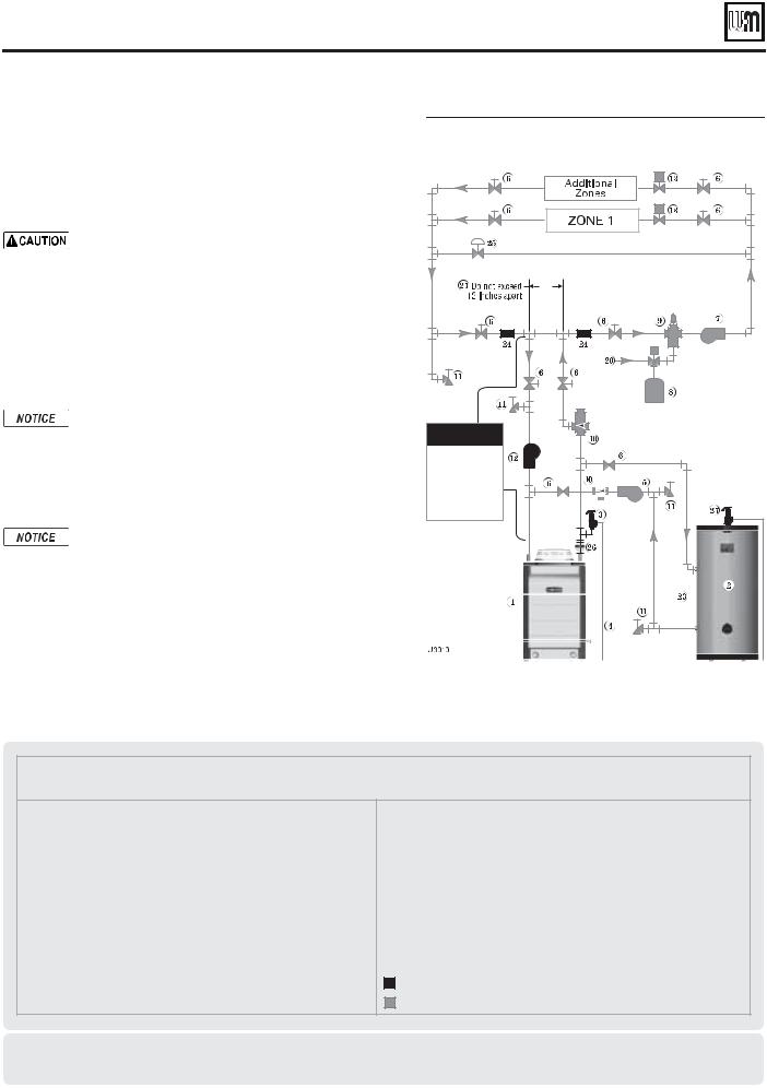
&IGURE Zone valve zoning plus optional DHW piping
-).)-5- |
Boiler loop pipe size
Ultra-80, 105 |
1” |
|
|
|
|
|||||
|
|
|
||||||||
Ultra-155, 230 |
1¼” |
|
|
|
||||||
Ultra-299/310, |
1½” |
|
|
|
|
|
|
|
|
|
399 |
|
|
|
|
|
|
|
|||
|
|
|
|
|
|
|
|
|
|
|
See CAUTION at left.
Legend — Figure 5
1Ultra boiler
2Indirect water heater (DHW), if used
3Boiler relief valve (see page 9 for piping details)
4 Relief valve discharge piping (see page 9 for details) 5 DHW circulator (see page 56 for suggested sizing)
6Isolation valves
7System circulator (see information above for wiring)
8Diaphragm (or bladder) type expansion tank (see page 56 for piping of closed-type expansion tank, if used)
9Air separator [with automatic air vent only on systems using diaphragm (or bladder) type expansion tank]
10Flow/check valves
11Purge/drain valves
12Boiler circulator
13Zone valves, typical
20Make-up water supply
21Primary/secondary connection
23DHW connections — see water heater manual for piping
24Strap system supply and return sensors to lines as shown, at least 6 pipe diameters (but no more than 3 feet) from boiler connection tees.
25Systems using high-head pumps may require a bypass pressure regulator to prevent damage to control valves.
26Temperature/Pressure gauge
27DHW relief valve, if used
Items supplied with boiler
Items supplied by others
Other piping alternatives
See page 14 and page 15 and ADVANCED INSTALLATION section for additional piping suggestions.
12 |
Part number 550-100-400/0717 |
 ® SERIES 4 GAS-FIRED WATER BOILER — Boiler Manual
Install water piping — typical systems (continued)
Zoning with circulators
1.Connect boiler to system as shown in Figure 6 when circulator zoning. The boiler circulator cannot be used for a zone. It must supply only the boiler loop. Also see the information on page 14 and page 15 for suggested piping and sizing.
Use AT LEAST the -).)-5- pipe size shown in Figure 6 on all boiler loop piping (connecting boiler to and from the primary/secondary connection, item 21). 5SESONLYY PRIMARY SECONDARYYPIPING AS SHOWN Failure to follow these guidelines could result in system problems.
2.Install a separate circulator for each zone.
3.When using a closed-type expansion tank, connect the expansion tank and make-up water piping as shown in Figure 4, page 11. (DO NOT use a closed-type tank with a AQUA PLUS water heater.)
4.Connect DHW (domestic hot water) piping to indirect storage water heater as shown.
By default, the U-Control Module turns off space heating during DHW heating (if DHW input is priority 1). The boiler circulator will turn off, preventing hot water from circulating to the system (optional timeout setting can be used to override). The flow/check valve shown on the boiler outlet piping prevents gravity circulation in the boiler loop during DHW heating.
Overriding the Outdoor Reset function by setting control to DHW mode when system is intended for space heating may violate Section 303 of the 2007 Energy Act. See page 137 for
compliance information and exemptions.
5.Controlling the circulators
a.The U-Control can control up to three circulators (boiler circulator and two others). Refer to Field wiring, beginning on page 30, for instructions on wiring to circulators.
b.The factory default settings are: DHW circulator as Circulator 1, boiler circulator as Circulator 2. See Field wiring instructions, beginning on page 30, for details.
c.The zone circulators in Figure 6 must be controlled by circulator relays activated by the zone thermostats or zone controller.
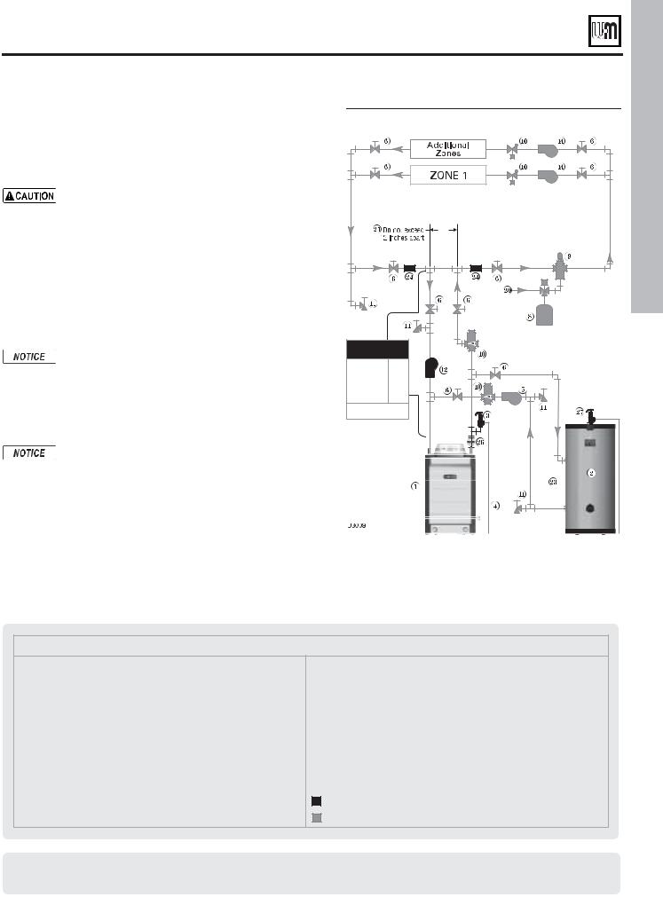
&IGURE Circulator zoning plus optional DHW piping |
||
-).)-5- |
||
Boiler loop pipe size |
||
Ultra-80, 105 |
1” |
|
Ultra-155, 230 |
||
1¼” |
||
Ultra-299/310, |
||
399 |
1½” |
|
|
||
See CAUTION at left. |
||
Legend — Figure 6
1Ultra boiler
2 Indirect water heater (DHW), if used (see page 56)
3Boiler relief valve (see page 9 for piping details)
4 Relief valve discharge piping (see page 9 for details)
5 DHW circulator (see page 56 for suggested sizing)
6Isolation valves
7System circulator (see information above for wiring)
8Diaphragm (or bladder) type expansion tank (see page 56 for piping of closed-type expansion tank, if used)
9Air separator [with automatic air vent only on systems using diaphragm (or bladder) type expansion tank]
10 Flow/check valves
11Purge/drain valves
12Boiler circulator
14 Zone circulators, typical
20Make-up water supply
21Primary/secondary connection (tees no more than 12 inches apart)
23DHW connections — see water heater manual for piping
24Strap system supply and return sensors to lines as shown, at least 6 pipe diameters (but no more than 3 feet) from boiler connection tees.
26Temperature/Pressure gauge
27DHW relief valve, if used
Items supplied with boiler
Items supplied by others
<![endif]>"!3)# ).34!,,!4)/.
Other piping alternatives
See page 14 and page 15 and ADVANCED INSTALLATION section for additional piping suggestions.
Part number 550-100-400/0717 |
13 |
 ® SERIES 4 GAS-FIRED WATER BOILER — Boiler Manual
Using with Weil-McLain AQUA PLUS water heaters
See !15!!0,53 - Product Manual for typical water piping.
See ADVANCED INSTALLATION section for additional piping information and applications.
AQUA PLUS DHW installation — quick- |
|
|
|
|
|
|
|
|
&IGURE Ultra boiler with Ultra PLUS or AQUA |
||||||||
selection |
||||||||
|
|
|
PLUS water heater — dedicated water |
|||||
The information in this section is for usage of Ultra boilers |
|
|
|
heating application, typical piping |
||||
|
|
|
schematic |
|||||
with Weil-McLain AQUA PLUS indirect water heaters. |
|
|
|
|
|
|
|
|
For dedicated DHW applications, use the circulator supplied with the boiler to circulate to the water heater as shown in this section.
By default, the U-Control Module turns off space heating during DHW heating (if DHW input is priority 1). The boiler circulator will turn off, preventing hot water from circulating to the system (optional timeout setting can be used to override).
DO NOT use a closed-type expansion tank on a system with a Weil-McLain AQUA PLUS water heater. The water heater must use an automatic air vent. Operation of the automatic air vent will deplete air in the piping, causing the expansion tank to waterlog. Always use a diaphragmor bladder-type expansion tank with AQUA PLUS water heaters.
1.Follow the guidelines on this page and page 15 to connect the water heater to the boiler. Use Figure 8 for dedicated water heating-only applications. Use Figure 9 and Figure 10, page 15 for combined space heating/water heating applications.
|
|
|
|
|
|
|
|
|
|
|
|
|
|
|
|
|
|
|
|
||||||||
|
|
|
|
|
|
|
|
|
|
|
|
|
|
|
|
|
|
|
|
|
|
|
|
||||
|
|
|
|
|
|
|
|
|
|
|
|
|
|
|
|
|
|
|
|
|
|
||||||
|
|
|
|
|
|
|
|
|
|
|
|
|
|
|
|
|
|
|
|
|
|
||||||
|
|
|
|
|
|
|
|
|
|
|
|
|
|
|
|
|
|
|
|
|
|
||||||
|
|
|
|
|
|
|
|
|
|
|
|
|
|
|
|
|
|
|
|
|
|||||||
|
|
|
|
|
|
|
|
|
|
|
|
|
|
|
|
|
|
|
|
||||||||
|
|
|
|
|
|
|
|
|
|
|
|
|
|
|
|
|
|
|
|
|
|
|
|
|
|
|
|
|
|
|
|
|
|
|
|
|
|
|
|
|
|
|
|
|
|
|
|
|
|
|
|
|
|
||
|
|
|
|
|
|
|
|
|
|
|
|
|
|
|
|
|
|
|
|
|
|
|
|
|
|||
|
|
|
|
|
|
|
|
|
|
|
|
|
|
||||||||||||||
|
|
|
|
|
|
|
|
|
|
|
|
|
|
|
|
|
|
|
|
|
|
|
|
|
|
|
|
6
2.The AQUA PLUS water heater can also be installed as one of the zones in the system. This method, however, requires flow through the main system even during the summer (non-space heating) months. Piping as shown in Figure 9 and Figure 10, page 15 allows isolation of flow to just the water heater piping during non-heating periods.
&IGURE Use the table below to size DHW loop piping and select a circulator (see ADVANCED section for other DHW tanks)
"OILER |
|
0ARTIAL LOAD SEE &IGUREA |
AND &IGURE PAGEE |
||||||
5LTRA |
COMBINEDBSPACEEHEATING WATEREHEATINGAAPPLICATION |
||||||||
|
|
|
|
|
|
|
|
||
|
0,53 |
|
'0- |
-"( |
'0( |
(EAD |
$(7 |
#)2# |
|
|
MODEL |
|
|
|
|
LOSS FT |
PIPE SIZE |
|
|
|
|
|
|
|
|
|
|
|
|
|
40 |
|
6.5 |
71/71 |
160/124 |
8.5 |
1 |
007 |
|
-"( |
|
|
|
|
|
|
|
|
|
60 |
|
6.5 |
71/71 |
168/132 |
8.5 |
1 |
007 |
||
|
|
||||||||
|
|
|
|
|
|
|
|
|
|
|
80 |
|
6.5 |
71/71 |
176/140 |
8.5 |
1 |
007 |
|
|
|
|
|
|
|
|
|
|
|
|
40 |
|
10.1 |
94/94 |
217/154 |
17.0 |
1¼ |
0014 |
|
-"( |
|
|
|
|
|
|
|
|
|
60 |
|
6.4 |
94/94 |
211/162 |
8.6 |
1 |
007 |
||
|
|
||||||||
|
|
|
|
|
|
|
|
|
|
|
80 |
|
6.4 |
94/94 |
219/170 |
8.6 |
1 |
007 |
|
|
|
|
|
|
|
|
|
|
|
|
40 |
|
12.1 |
119/98 |
248/160 |
15.9 |
1¼ |
0014 |
|
-"( |
|
|
|
|
|
|
|
|
|
60 |
|
12.1 |
139/120 |
295/220 |
15.9 |
1¼ |
0014 |
||
|
|
||||||||
|
|
|
|
|
|
|
|
|
|
|
80 |
|
12.1 |
139/139 |
305/230 |
15.9 |
1¼ |
0014 |
|
|
|
|
|
|
|
|
|
|
|
|
40 |
|
13.5 |
120/100 |
251/162 |
15.2 |
1¼ |
0014 |
|
-"( |
|
|
|
|
|
|
|
|
|
60 |
|
18.4 |
169/128 |
350/207 |
23.7 |
1½ |
1400-20 |
||
|
|
||||||||
|
|
|
|
|
|
|
|
|
|
|
80 |
|
13.5 |
207/207 |
430/325 |
15.2 |
1¼ |
0014 |
|
|
|
|
|
|
|
|
|
|
|
|
40 |
|
13.1 |
120/100 |
250/162 |
9.7 |
1¼ |
0010 |
|
-"( |
|
|
|
|
|
|
|
|
|
60 |
|
19.3 |
170/129 |
351/208 |
11.7 |
1½ |
0014 |
||
|
|
||||||||
|
|
|
|
|
|
|
|
|
|
|
80 |
|
24.9 |
252/252 |
510/381 |
18.4 |
1½ |
1400-20 |
|
|
|
|
|
|
|
|
|
|
|
|
40 |
|
13.1 |
120/100 |
250/162 |
9.7 |
1¼ |
0010 |
|
-"( |
|
|
|
|
|
|
|
|
|
60 |
|
19.3 |
170/129 |
351/208 |
11.7 |
1½ |
0014 |
||
|
|
||||||||
|
|
|
|
|
|
|
|
|
|
|
80 |
|
24.9 |
320/253 |
636/382 |
18.4 |
1½ |
1400-20 |
|
|
|
|
|
|
|
|
|
|
|
$EDICATEDCBOILER SEEB&IGURE
WATER HEATING ONLY
0,53 |
'0- |
-"( |
|
'0( |
(EAD |
$(7 |
|
#)2# |
MODEL |
|
|
|
|
LOSS FT |
PIPE SIZE |
|
|
|
|
|
|
|
|
|
|
|
40 |
6.5 |
71/71 |
|
160/124 |
8.5 |
1 |
|
007 |
|
|
|
|
|
|
|
|
|
60 |
6.5 |
71/71 |
|
168/132 |
8.5 |
1 |
|
007 |
|
|
|
|
|
|
|
|
|
80 |
6.5 |
71/71 |
|
176/140 |
8.5 |
1 |
|
007 |
|
|
|
|
|
|
|
|
|
40 |
6.4 |
94/86 |
|
203/141 |
8.6 |
1 |
|
007 |
|
|
|
|
|
|
|
|
|
60 |
6.4 |
94/94 |
|
211/162 |
8.6 |
1 |
|
007 |
|
|
|
|
|
|
|
|
|
80 |
6.4 |
94/94 |
|
219/170 |
8.6 |
1 |
|
007 |
|
|
|
|
|
|
|
|
|
40 |
12.1 |
119/98 |
|
248/160 |
15.9 |
1¼ |
|
0014 |
|
|
|
|
|
|
|
|
|
60 |
12.1 |
139/120 |
|
295/220 |
15.9 |
1¼ |
|
0014 |
|
|
|
|
|
|
|
|
|
80 |
12.1 |
139/139 |
|
305/230 |
15.9 |
1¼ |
|
0014 |
|
|
|
|
|
|
|
|
|
40 |
|
Not recommended — boiler capacity |
|
|||||
|
|
|
||||||
60 |
|
exceeds maximum output of water heater |
|
|||||
|
|
|
|
|
|
|
|
|
|
|
|
|
|
|
|
|
|
80 |
13.5 |
207/207 |
|
430/325 |
15.2 |
1¼ |
|
0014 |
|
|
|
|
|
|
|
|
|
40 |
|
|
|
|
|
|
|
|
|
|
|
|
|
|
|
|
|
60 |
|
|
|
|
|
|
|
|
|
|
|
|
Not recommended — |
|
|||
80 |
|
|
|
|
||||
|
|
|
boiler capacity exceeds |
|
||||
40 |
|
|
|
|||||
|
maximum output of water heater |
|
||||||
|
|
|
|
|
|
|
|
|
60 |
|
|
|
|
|
|
|
|
|
|
|
|
|
|
|
|
|
80 |
|
|
|
|
|
|
|
|
|
|
|
|
|
|
|
|
|
14 |
Part number 550-100-400/0717 |

 ® SERIES 4 GAS-FIRED WATER BOILER — Boiler Manual
Using with Weil-McLain AQUA PLUS water heaters (cont.)
See !15!!0,53 - Product Manual for typical water piping.
&IGURE Ultra boiler with Ultra PLUS or AQUA PLUS-40, -60 or -80 water heater, zone valve zoning, typical piping
"OILER LOOPRPIPE SIZE |
3YSTEM ZONEMPIPE SIZING |
||
"ASEBOARD CONVECTOR OROCAST IRON |
|||
|
|
||
80, -105 |
1” or larger |
RADIATORSS/.,9 |
|
155, -230 |
1¼” or larger |
For residential space heating appli- |
|
299/310, 399 |
1½ or larger |
cations (other than radiant heating |
|
or unit heaters) ONLY, you can use: |
|||
|
|
||
$(7(LOOP PIPEOSIZE
See Figure 7, page 14
|
5LTRAT-ODEL |
|
3YSTEM HEADER |
||||
|
|
|
|
|
|
|
|
|
-80 |
|
|
1” or larger |
|||
|
-105, -155 |
|
1¼” or larger |
||||
|
-230 |
|
|
1½” or larger |
|||
|
-299/310, 399 |
|
2” or larger |
||||
|
Recommendations are based on a 20°F temp |
||||||
|
drop through the system. |
|
|
||||
|
|
|
|
|
|
||
|
Zone piping selection for series loops |
||||||
|
with finned-tube baseboard — general |
||||||
|
|
|
|
|
|
||
|
Copper pipe and |
|
Max recommended |
||||
|
baseboard size |
|
feet of baseboard |
||||
|
|
|
|
|
|
|
|
|
¾" |
|
|
|
106 |
||
|
1" |
|
|
|
179 |
||
|
Contact your supplier to size the system and zone |
||||||
|
circulators needed. See below for zone piping |
||||||
|
using Taco 007 or equivalent circulators. |
||||||
|
|
|
|
|
|||
|
Limits for series loop zones with |
||||||
|
finned-tube baseboard using |
||||||
|
Taco 007 (or equivalent) circulators |
||||||
|
|
|
|
|
|
|
|
|
Copper |
|
Max |
|
Max feet of |
Max total |
|
|
pipe and |
|
load |
|
length of |
||
|
|
|
baseboard |
||||
|
baseboard |
|
MBH |
|
circuit (feet) |
||
|
|
|
|
|
|||
|
|
|
|
|
|
|
|
|
¾" |
|
50 |
82 |
|
93 |
|
|
1" |
|
79 |
104 |
|
123 |
|
&IGURE Ultra boiler with Ultra PLUS or AQUA PLUS water heater, typical piping |
,EGENDNfor Figure 9 and Figure 10 |
schematics |
DHW circulator (see page 56 for suggested |
|
sizing) |
|
|
|
|
|
|
|
|
|
|
|
|
|
|
|
|
|
|
|
|
|
|
"EEJUJPOBM |
|
|
|
|
|
|
|
|
|
|
|
|
|
|
|
|
|
;POFT |
|
|
|
|
|
|
|
|
|
"EEJUJPOBM |
|
|
|
|
|
|
|
|
|
|
|
|
|
|
|
|
;POFT |
|
|
|
|
|
;0/& |
|
|
|
|
|
|
|
|
|
|
;0/& |
|
|
;0/& |
|
|
|
|
|
|
|
|
|
|
|
|
|
|
|
|
|
||
|
|
|
|
|
;0/& |
|
%P OPU FYDFFE |
:ONE VALVE ZONING |
JODIFT BQBSU |
#IRCULATORAZONING |
|||
|
|
|
|
%P OPU FYDFFE |
|
|
JODIFT BQBSU |
|
|
|
|
|
|
|
|
|
|
|
|
|
|
|
|
|
|
|
|
|
|
|
|
|
|
|
|
|
|
|
|
|
|
|
|
|
|
|
|
|
|
||||||||||||||||||||||||
|
|
|
|
|
|
|
|
|
|
|
|
|
|
|
|
|
|
|
|
|
|
|
|
|
|
|
|
|
|
|
|
|
|
|
|
|
|
|
|
|
|
|
|
|
|
|
|
|
|||
|
|
|
|
|
|
|
|
|
|
|
|
|
|
|
|
|
|
|
|
|
|
|
|
|
|
|
|
|
|
|
|
|
|
|
|
|
|
|
|
|
|
||||||||||
|
|
|
|
|
|
|
|
|
|
|
|
||||||||||||||
|
|
|
|||||||||||||||||||||||
6 |
|
|
|
|
|
|
|
|
|
|
|
|
|
6 |
|
|
|
|
|
|
|
|
|
|
|
|
|
|
|
|
|
|
|
|
|
|
|
|
|
|
|
|
|
|
|
|
|
|
|
||
Part number 550-100-400/0717
System circulator (provided by installer)
Diaphragm type expansion tank ONLY
— DO NOT use a closed-type tank with AQUA PLUS water heaters, because the automatic air vent will deplete the air from the system, causing the expansion tank to waterlog.
Air separator with automatic air vent Flow/check valves
Boiler circulator — provided with boiler Zone valves, typical
Make-up water supply Primary/secondary connection
DHW connections — see water heater manual for piping
Strap system supply and return sensors to lines as shown, at least 6 pipe diameters (but no more than 3 feet) from boiler connection tees.
Systems using high-head pumps may require a bypass pressure regulator to prevent damage to control valves.
DHW relief valve must be installed in the tapping on top of the AQUA PLUS water heater.
Items supplied with boiler Items supplied by others
15
<![endif]>"!3)# ).34!,,!4)/.
 ® SERIES 4 GAS-FIRED WATER BOILER — Boiler Manual
Venting/air piping — general
Do not install the Ultra boiler into a common vent with any other appliance. This will cause flue gas spillage or appliance malfunction, resulting in possible severe personal injury, death or substantial property damage.
Existing common vent systems may be too large for the appliances remaining connected after the existing boiler is removed.
Failure to follow all instructions can result in flue gas spillage and carbon monoxide emissions, causing severe personal injury or death.
When removing a boiler from an existing common vent system
4HEH5LTRATBOILER CANNOT BE COMMON VENTED WITH ANYYOTHERHAPPLI ANCE. When an existing boiler is replaced with an Ultra boiler, the Ultra boiler CANNOT use the existing common vent. The Ultra boiler requires its own vent and air piping, as specified in this manual. This may cause a problem for the appliances that remain on the old common vent, because the vent may be too large. The following test is intended to check for proper operation of the appliances remaining on the old common vent system.
Vent system verification
At the time of removal of an existing boiler, the following steps shall be followed with each appliance remaining connected to the common venting system placed in operation, while the other appliances remaining connected to the common venting system are not in operation. Seal any unused openings in the common venting system.
Existing vent test procedure
(The following is intended to test whether the appliances remaining on an existing vent system will operate satisfactorily.)
1.Visually inspect the venting system for proper size and horizontal pitch and determine there is no blockage or restriction, leakage, corrosion or other deficiencies which could cause an unsafe condition.
2.Test vent system — Insofar as is practical, close all building doors and windows and all doors between the space in which the appliances remaining connected to the common venting system are located and other spaces of the building. Turn on clothes dryers and any appliance not connected to the common venting system. Turn on any exhaust fans, such as range hoods and bathroom exhausts, so they will operate at maximum speed. Do not operate a summer exhaust fan. Close fireplace dampers.
3.Place in operation the appliance being inspected. Follow the lighting instructions. Adjust thermostat so appliance will operate continuously.
4.Test for spillage at draft hood relief opening after 5 minutes of main burner operation. Use the flame of a match or candle, or smoke from a cigarette, cigar, or pipe.
5.After it has been determined that each appliance remaining connected to the common venting system properly vents when tested as outlined herein, return doors, windows, exhaust fans, fireplace dampers, and any other gas-burning appliance to their previous conditions of use.
Any improper operation of common venting system should be corrected so the installation conforms with the National Fuel Gas Code, ANSI Z223.1
— latest edition. Correct by re-sizing to approach the minimum size as determined using the appropriate tables in Part 11 of that code. Canadian installations must comply with B149.1 or B149.2 Installation Code.
16
99OU MUSTS PROVIDE COMBUSTION AIR.
$IRECT VENT — Install air inlet piping for the Ultra boiler as described in the Boiler manual and this addendum. The air termination fitting must be installed with the clearances and geometry relative to the vent outlet depicted in this manual to ensure that flue products do not enter the air intake.
$IRECT EXHAUST— Provide combustion air openings to boiler room/building as specified in this addendum and as required by all applicable codes.
%NSURE THAT THEHCOMBUSTION AIRIWILL NOTOCONTAIN ANYYOF THEHCONTAMINANTS IN &IGURE . $/ ./4 place combustion air supply opening or intake near a swimming pool, for example. Avoid areas subject to exhaust fumes from laundry facilities. These areas will always contain contaminants.
Contaminated combustion air will damage the boiler, resulting in possible severe personal injury, death or substantial property damage.
&IGURE Corrosive contaminants and sources
Products to avoid
Spray cans containing chloro/fluorocarbons
Permanent wave solutions
Chlorinated waxes/cleaners
Chlorine-based swimming pool chemicals
Calcium chloride used for thawing
Sodium chloride used for water softening
Refrigerant leaks
Paint or varnish removers
Hydrochloric acid/muriatic acid
Cements and glues
Antistatic fabric softeners used in clothes dryers
Chlorine-type bleaches, detergents, and cleaning solvents found in household laundry rooms
Adhesives used to fasten building products and other similar products
Excessive dust and dirt
Areas likely to have contaminants
Dry cleaning/laundry areas and establishments
Swimming pools
Metal fabrication plants
Beauty shops
Refrigeration repair shops
Photo processing plants
Auto body shops
Plastic manufacturing plants
Furniture refinishing areas and establishments
New building construction
Remodeling areas
Garages with workshops
Buildings under construction (where air is contaminated with particulates)
Part number 550-100-400/0717
 ® SERIES 4 GAS-FIRED WATER BOILER — Boiler Manual
Venting/air piping — general (continued)
5LTRAT"OILERSSMUSTSBE VENTED ANDNSUPPLIED WITH COMBUSTION ANDNVENTILATIONLAIRIUSINGI PIPING ANDNMETHODSHDESCRIBEDRIN THIS MANUAL.
%VERYYBOILER MUSTSHAVE ITSTOWN VENT. $/
./4 common vent with any other appliance. See page 16.
Inspect finished vent and air piping thoroughly to ensure all are airtight and comply with the instructions provided and with all requirements of applicable codes.
Failure to provide a properly-installed vent and air system will cause severe personal injury or death.
Combustion air piping
1.Combustion air must be piped from outside to the boiler, following the instructions in this manual, and compliant with all applicable codes. Read the warning in Figure 11, page 16, and ensure the air intake will not be likely to draw in contaminated air.
2.Combustion air can be piped individually for each boiler, or it can be manifolded as shown in Figure 59, page 59. Air piping must always terminate on the same side (or roof ) of the building as the vent.
Vent piping
1.Boiler flue gases must be piped from the boiler to outside, following the instructions in this manual, and compliant with all applicable codes. The vent pipe must terminate either through the sidewall or through the roof, located with the correct separation from the air termination. See Figure 14, page 18, and the associated instructions referenced.
2.Each Ultra boiler requires a separate vent. Do not common vent.
Venting/combustion air piping - Installations must provide provisions for combustion and ventilation air in accordance with the section “Air for Combustion and Ventilation,” of the National Fuel Gas Code - ANSI Z223.1/ NFPA54 – latest edition, or Sections 8.2, 8.3, or 8.4 of Natural Gas and Propane Installation Code - CAN/CSA B149.1, or applicable provisions of the local building codes.
Use only the materials listed in this manual for vent and air pipe and fittings. Failure to comply could result in severe personal injury, death or substantial property damage.
If used, a masonry chimney can ONLY be used as a PIPE CHASE for vent and air pipes — The vent and air piping must be installed as instructed in this manual and all joints must be sealed. The chimney must be used only for Ultra boilers. NO OTHER appliance or fireplace can be connected to the chimney.
The chimney must be straight, with no offsets, and the vent and air piping materials must comply with this instruction manual.
The chimney must be fitted with a sealed access opening, through which the interior of the chimney can be inspected.
The chimney and liner must be inspected at least once annually to verify condition.
Failure to comply could result in severe personal injury, death or substantial property damage.
Vent and air piping materials
1.See Figure 13, page 19 for approved vent and air piping materials.
Part number 550-100-400/0717 |
17 |
<![endif]>"!3)# ).34!,,!4)/.
 ® SERIES 4 GAS-FIRED WATER BOILER — Boiler Manual
Venting & air — general (cont.)
&IGURE Vent and air pipe options and maximum allowable piping lengths
| <![if ! IE]> <![endif]>Ultra model |
<![if ! IE]> <![endif]>Vent or air pipe size |
2” *
-80/105
3”
-155 3”
3”
-230
4”
-299 4”
-310 4”
-399 4”
Note 1:
Additional
notes
t .BYJNVN FRVJWBMFOU GFFU PG QJQJOH t /VNCFS PG FMCPXT BMMPXFE BU UIFTF MFOHUIT
(All applications include allowance for the terminations.)
Direct vent |
Direct vent |
3” Concentric |
4” Concentric |
Direct vent |
Direct vent |
||||||||||||
Sidewall |
Sidewall with |
Sidewall or Vertical |
Sidewall or Vertical |
Vertical |
Vertical exhaust |
||||||||||||
with |
|
separate pipes |
DO NOT use CPVC |
DO NOT use CPVC |
with separate |
Sidewall air |
|||||||||||
Weil-McLain |
— or — |
|
or ABS |
|
or ABS) |
|
pipes |
|
|
|
|
||||||
vent/air cap |
%JSFDU FYIBVTU |
|
[Note 1] |
|
[Note 1] |
|
|
|
|
|
|
|
|||||
|
|
|
(sidewall or vertical) |
|
|
|
|
|
|
|
|
|
|
|
|
|
|
|
|
|
|
|
|
|
|
|
|
|
|
|
|||||
Direct vent |
Direct vent or |
|
Direct vent |
Direct vent |
Direct vent |
Direct vent |
|||||||||||
only |
|
Direct exhaust |
|
only |
|
only |
|
only |
|
only |
|
||||||
|
|
|
|
|
|
|
|
|
|
|
|
|
|
|
|
|
|
Length |
|
Ells |
Length |
Ells |
Length |
|
Ells |
Length |
|
Ells |
Length |
|
Ells |
Length |
|
Ells |
|
100 (ab) |
|
|
100 (a) |
|
|
(ab) |
|
|
|
|
|
100 (a) |
|
|
100 (a) |
|
|
|
2 |
2 |
100 |
|
1 |
NA |
|
|
1 |
|
1 |
||||||
|
|
|
|
|
|
|
|
|
|
|
|
|
|
|
|
||
100 |
|
2 |
100 |
2 |
100 |
|
1 |
NA |
|
100 |
|
1 |
100 |
|
1 |
||
|
|
|
|
|
|
|
|
|
|
|
|
|
|
|
|
||
100 |
|
2 |
100 |
2 |
100 |
|
1 |
NA |
|
100 |
|
1 |
100 |
|
1 |
||
|
|
|
|
|
|
|
|
|
|
|
|
|
|
|
|
||
30 (c) |
|
2 |
30 (c) |
2 |
30 (c) |
|
1 |
30 (c)(d) |
|
1 |
30 (c) |
|
1 |
30 (c) |
|
1 |
|
|
|
|
|
|
|
|
|
|
|
|
|
|
|
|
|
|
|
100 (d) |
|
2 |
100 |
2 |
70 |
(d) |
|
1 |
100 |
|
1 |
100 |
|
1 |
100 |
|
1 |
|
|
|
|
|
|
|
|
|
|
|
|
|
|
|
|
|
|
100 |
|
2 |
100 |
2 |
70 |
(d) |
|
1 |
100 |
|
1 |
100 |
|
1 |
100 |
|
1 |
|
|
|
|
|
|
|
|
|
|
|
|
|
|
|
|
|
|
100 |
|
2 |
100 |
2 |
70 |
(d) |
|
1 |
100 |
|
1 |
100 |
|
1 |
100 |
|
1 |
|
|
|
|
|
|
|
|
|
|
|
|
|
|
|
|
|
|
100 |
|
2 |
100 |
2 |
|
NA |
|
100 |
|
1 |
100 |
|
1 |
100 |
|
1 |
|
|
|
|
|
|
|
|
|
|
|
|
|
|
|
|
|
|
|
IPEX 3” and 4” PVC concentric vent kits can be used with standard PVC pipe, fittings and cement (ANSI/ASTM D1785) except where ULC S636 compliance is required. For ULC S636 compliance, all pipe, fittings and cement must be IPEX System 636. When using IPEX kits, use only IPEX product code 196006 for 3” venting or IPEX product code 196021 for 4” venting.
Contact Weil-McLain for ordering information and availability of Weil-McLain venting kits.
Polypropylene - Separate pipe and concentric termination by respective manufacturers.
a — Use 3”x2” reducer at boiler |
c — Use 4”x3” reducer at boiler |
b — Use 3”x2” reducers at termination |
d — Use 4”x3” reducers at termination |
|
|
* Ultra-80 and 105 boilers installed with 2-inch vent piping automatically derate due to the pressure loss in the vent and air piping. The derate ranges up to 10% for the Ultra-80 at 100 feet or 15% for the Ultra-105 at 100 feet.
Equivalent feet for elbows — deduct from maximum equivalent length of piping:
PVC ss FEETPEREFORTEACHH INCHHELBOWW OR INCHH LONG RADIUSOR RELBOW
|
ss FEETFOREACHH OR INCHHSHORT RADIUSIELBOW |
|
||
PP |
ssCentrotherm 3” = 6’ |
4” = 20’ |
Duravent 3” = 17’ |
4” = 22’ |
Stainless steel (AL29-4C) vent pipe
install an adapter at the boiler for all applications. Also install an adapter at the termination unless using separate-pipe termination.
18 |
Part number 550-100-400/0717 |
 ® SERIES 4 GAS-FIRED WATER BOILER — Boiler Manual
Venting & air — general (cont.)
&IGURE Vent and air piping materials — Use only the materials listed below, ensuring that all materials meet local codes
)TEM |
-ATERIAL |
3TANDARDS FOR INSTALLATIONS IN |
||
|
|
|||
5NITED 3TATES |
#ANADA |
|||
|
|
|||
|
|
|
|
|
|
0LASTICSPIPING MATERIALS |
|
||
|
|
|
|
|
|
PVC schedule 40 |
ANSI/ASTM D1785 |
|
|
6ENTNOR AIR PIPEA |
|
|
|
|
PVC-DWV (Note 1) |
ANSI/ASTM D2665 |
Plastic vent pipe must be |
||
|
|
|
||
|
|
|||
lTTINGS |
CPVC schedule 40 (Note 1) |
ANSI/ASTM F441 |
certified to ULC S636 when |
|
|
|
|
required. (Note 2) |
|
|
ABS-DWV schedule 40 (Note 1) |
ANSI/ASTM D2661 |
||
|
Air pipe can be any of those |
|||
|
|
|
||
|
PVC |
ANSI/ASTM D2564 |
||
|
listed at left if acceptable for |
|||
06#6 #!"3 PIPE |
|
|
local codes. |
|
CPVC (Note 1) |
ANSI/ASTM F493 |
|||
|
||||
CEMENT PRIMER |
|
|||
|
|
|
||
|
ABS (Note 1) |
ANSI/ASTM D2235 |
|
|
|
|
|
|
|
Polypropylene |
3IMPSON $URAVENT Obtain all materials from |
See manufacturer’s literature for detailed |
|
|
vent pipe, |
M&G Simpson-Duravent |
information |
|
|
|
#ENTROTHERM %CO 3YSTEMS )NNO&LUE® 3INGLE |
MUST USE LOCKING COLLAR ON |
ULC S636 |
|
terminations |
WALL Obtain all materials from Centrotherm |
EVERY JOINT |
||
|
||||
|
|
|
|
|
|
!, # PIPING MATERIALS |
|
||
|
|
|
|
|
6ENTNPIPE |
Heat Fab, Inc. — Saf-T-Vent® |
|
Certified for Category IV and |
|
!, # |
|
Certified for Category IV and direct vent |
||
Z-Flex, Inc. — Z-Vent II |
direct vent |
|||
STAINLESS |
appliance venting |
|||
|
appliance venting |
|||
STEEL |
Simpson Dura-Vent — FasNSeal™ |
|
||
|
|
|||
|
|
|
|
|
7EIL -C,AIN BIRDDSCREENSR(purchase separately)
7EIL -C,AIN |
For 2” or 3” vent or air termination |
For 3” or 4” vent or air termination |
(cut to size if necessary) |
(cut to size if necessary) |
|
BIRD |
3” vent screen: |
4” vent screen: |
SCREENS |
||
|
W-M part number 383-500-105 |
W-M part number 383-500-110 |
|
|
|
Note 1: DO NOT use DWV, CPVC or ABS when using concentric vent termination. Use ONLY PVC schedule 40.
Note 2: IPEX PVC concentric terminations utilize PVC pipe/fittings certified to ULC S636. Where ULC S636 compliance is required, use only IPEX System 636 pipe, fittings and cement.
AL29-4C vent piping — Install a PVC-to-stainless adapter supplied by the vent pipe manufacturer at the boiler vent connection and at the termination (when using Weil-McLain plate or concentric PVC termination). DO NOT mix piping from different vent pipe manufacturers unless using adapters specifically designed for the purpose by the manufacturer.
Plastic piping — Do not attempt to connect different types of plastic piping together.
DO NOT use cellular core pipe.
All vent and air pipes require a BIRDDSCREEN AT EACHHTERMINATION where specified in the manual or vent supplement. Purchase bird screens separately from Weil-McLain or vent kit supplier. Note that most kits do not include the screens.
<![endif]>"!3)# ).34!,,!4)/.
Part number 550-100-400/0717 |
19 |
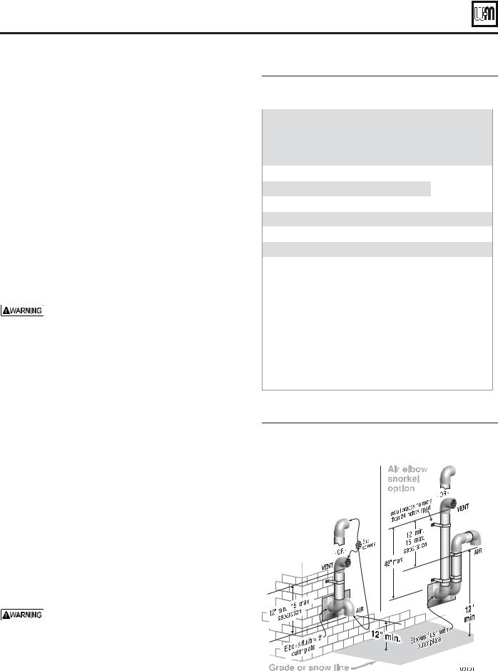
 ® SERIES 4 GAS-FIRED WATER BOILER — Boiler Manual
Sidewall vent/air termination: Separate pipes
Allowable vent/air pipe materials
1.Use only the materials listed in Figure 13, page 19.
2.The Weil-McLain vent termination kit includes inside and outside wall plates, bird screens, and mounting hardware to secure the plates (kit included with boiler).
Maximum piping length
1.Locate the terminations such that the total air piping and vent piping from the boiler to the termination will not exceed the maximum length given in Figure 14.
2.Maximum lengths listed in Figure 14 allow for 2 elbows. Additional elbows required a reduction in maximum length as explained in the table notes.
Connecting from termination to boiler
1.Install the terminations as instructed in the following. Then proceed to page 82 to complete the air and vent piping between the termination and the boiler.
Determine location — separate elbows
A gas vent extending through an exterior wall shall not terminate adjacent to the wall or below building extensions such as eaves, parapets, balconies or decks. Failure to comply could result in severe personal injury, death or substantial property damage.
1.Locate the vent/air terminations using the following guidelines.
2.The air piping must terminate in a down-turned elbow as shown in Figure 15. This arrangement avoids recirculation of flue products into the combustion air stream.
a.Apply the configuration on the left side of Figure 15 unless the terminations would fail to meet minimum clearance to grade or snow line.
b.Apply the configuration on the right side of Figure 15 when the terminations need to be raised higher to meet clearance to grade or snow line.
c.The vent and air pipes may run up as high as 4 feet, as shown in Figure 15 right side with no enclosure. The vent and air pipes must be secured with braces, and all clearances and lengths must be maintained. Space braces no further than 24 inches apart. (See WARNING below for extremely cold climates.)
d.External venting greater than 4 feet requires an insulated enclosure around the vent and air pipes. The vent and air terminations must exit through the enclosure as shown in Figure 15, maintaining all required clearances.
3.The vent piping must terminate in an elbow pointed outward or away from the air inlet, as shown in Figure 15.
Do not exceed the maximum lengths of the outside vent piping shown in Figure 15. Excessive length exposed to the outside could cause freezing of condensate in the vent pipe, resulting in potential boiler shutdown. In extremely cold climates, install an insulated chase around the vent piping, particularly when using longer lengths. The chase must allow for inspection of the vent pipe, and insulation must be protected from water.
&IGURE -AXIMUM PIPINGILENGTHSGFOR SEPARATEPVENT
ANDNAIR PIPE SIDEWALL TERMINATION
"OILER |
-AXIMUM |
-AXIMUM |
-AXIMUM |
|||||
5LTRA |
0IPING v |
0IPING v |
0IPING v |
|||||
|
|
|
|
|
|
|
|
|
|
Feet |
Elbows |
Feet |
Elbows |
Feet |
|
Elbows |
|
|
|
|
|
|
|
|
|
|
-80 ** |
100 |
2 |
100 |
2 |
|
|
|
|
|
|
|
|
|
|
Not |
||
-105 ** |
100 |
2 |
100 |
2 |
|
|||
allowed |
||||||||
|
|
|
|
|
||||
-155 |
Not allowed |
100 |
2 |
|||||
|
|
|
||||||
|
|
|
|
|
|
|||
-230 |
Not allowed |
30 |
2 |
100 |
|
2 |
||
|
|
|
|
|
|
|
||
-299/310 |
Not allowed |
Not allowed |
100 |
|
2 |
|||
|
|
|
|
|
|
|||
-399 |
Not allowed |
Not allowed |
100 |
|
2 |
|||
|
|
|
|
|
|
|
|
|
* Install pipe reducers to adapt from pipe size used to the outside diameter required at the boiler. You do not have to reduce allowable pipe length for the reducers.
** Ultra-80 and 105 boilers installed with 2-inch vent piping automatically derate due to the pressure loss in the vent and air piping. The derate ranges up to 10% for the Ultra-80 at 100 feet or
15% for the Ultra-105 at 100 feet.
For piping using more than 2 elbows, reduce maximum allowable length:
sFEETEFOR EACHEADDITIONAL INCHTELBOWW OR
sFEETEFOR EACHEADDITIONAL ORI INCH LONGLRADIUSIELBOW
ssFEETEFOR EACHE AOR INCH SHORTTRADIUSIELBOW
sFEETEFOR EACHE AOR INCH DEGREEEELBOW
&IGURE Sidewall termination — separate pipes — configuration options and minimum clearances from vent to air terminations
20 |
Part number 550-100-400/0717 |
 ® SERIES 4 GAS-FIRED WATER BOILER — Boiler Manual
Sidewall vent/air termination: Separate pipes (continued)
4.You must consider the surroundings when terminating the vent and air:
a.Position the vent termination where vapors will not damage nearby shrubs, plants or air conditioning equipment or be objectionable.
b.The flue products will form a noticeable plume as they condense in cold air. Avoid areas where the plume could obstruct window views.
c.Prevailing winds could cause freezing of condensate and water/ice buildup where flue products impinge on building surfaces or plants.
d.Avoid possibility of accidental contact of flue products with people or pets.
e.Do not locate the terminations where wind eddies could affect performance or cause recirculation, such as inside building corners, near adjacent buildings or surfaces, window wells, stairwells, alcoves, courtyards or other recessed areas.
f.Do not terminate above any door or window or under a deck. Condensate can freeze, causing ice formations.
g.Locate or guard vent to prevent condensate damage to exterior finishes.
5.Maintain clearances as shown in the illustrations in this manual section. Also maintain the following:
a.Vent must terminate:
ss At least 6 feet from adjacent walls.
ss No closer than 5 feet below roof overhang. ss At least 7 feet above any public walkway.
ss At lease 3 feet above any forced air intake within 10 feet.
ssNo closer than 12 inches below or horizontally from any door or window or any other gravity air inlet.
b.Do not terminate closer to 4 feet horizontally from any electric meter, gas meter, regulator, relief valve or other equipment. Never terminate above or below any of these within 4 feet horizontally.
6.Locate terminations so they are not likely to be damaged by foreign objects, such as stones or balls, or subject to buildup of leaves or sediment.
7.Do not connect any other appliance to the vent pipe or multiple boilers to a common vent pipe.
Completing the vent/air piping
1.Install vent/air penetrations as explained in the following pages before installing vent and air piping from the boiler to the terminations. Insert piping from boiler air and vent connections, then attach exterior termination piping.
2.Follow instructions beginning on page 71 to complete piping from boiler to termination.
&IGURE Sidewall termination with separate pipes — clearances to openings
&IGURE Sidewall termination with separate pipes — clearances to public walkway or forced air intake
&IGURE Multiple terminations — separate pipes — clearance from vent of one to air intake of the next
<![endif]>"!3)# ).34!,,!4)/.
-AINTAIN ALL REQUIREMENTS SHOWN IN 
&IGURE PAGEE
Part number 550-100-400/0717 |
21 |
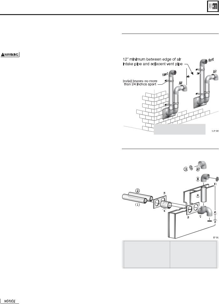
 ® SERIES 4 GAS-FIRED WATER BOILER — Boiler Manual
Sidewall vent/air termination: Separate pipes (continued)
Multiple vent/air terminations
1.When terminating multiple Ultra boilers, terminate each vent/air connection as described in this manual.
All vent pipes and air inlets must terminate at the same height to avoid possibility of severe personal injury, death or substantial property damage.
2.Place wall penetrations to obtain minimum clearance of 12 inches between vent pipe and adjacent air inlet elbow, as shown in Figure 18, page 21 for U. S. installations.
3.For Canadian installations, provide clearances required by Natural Gas and Propane Installation CAN/CSA B149.1 or B149.2 Installation Code.
4.The air inlet of an Ultra boiler is part of a direct vent connection. It is not classified as a forced air intake with regard to spacing from adjacent boiler vents.
5.Combustion air (NOT vent piping) can be manifolded as shown in Figure 59, page 59.
Prepare wall penetrations
1.Air pipe penetration:
a.Cut a hole for the air pipe. Size the air pipe hole as close as desired to the air pipe outside diameter.
2.Vent pipe penetration:
a.Cut a hole for the vent pipe. For either combustible or noncombustible construction, size the vent pipe hole at least 0.4” larger than the vent pipe diameter:
ss 2¾” hole for 2”
ss 4” hole for 3”
ss 5” hole for 4”
b.Insert a galvanized metal thimble in the vent pipe hole as shown in Figure 20.
3.Use a sidewall termination plate as a template for correct location of hole centers. Sidewall termination plates must be purchased separately. See the parts list at the end of this manual for part numbers.
4.Follow all local codes for isolation of vent pipe when passing through floors or walls.
5.Seal exterior openings thoroughly with exterior caulk.
Termination and fittings
1.Prepare the vent termination elbow and the air termination elbow (Figure 20) by inserting bird screens. Bird screens must be purchased separately. See the parts list at the end of this manual for part numbers.
2.When completed, the air termination coupling must be oriented at least 12 inches below the vent termination and at least 12 inches above grade or snow line as shown in Figure 15, page 20.
3.You can orient the vent termination elbow either directly outward or 90 degrees away from the air inlet elbow as shown in Figure 15, page 20.
4.Maintain the required dimensions of the finished termination piping as shown in Figure 15, page 20.
5.Do not extend exposed vent pipe outside of building more than shown in this document. Condensate could freeze and block vent pipe.
If extending the vent and air pipes out from the wall, install a coupling on each pipe. Mount the piping with the coupling flush with the outer plate.
&IGURE Multiple terminations — separate pipes — clearance from vent of one to air intake of the next — alternate configuration of air and vent terminations
-AINTAIN ALL REQUIREMENTS
SHOWN IN &IGURE PAGEE
&IGURE Sidewall termination assembly — using separate pipes
1 |
Vent piping |
7 |
Elbow |
|
2 |
Air piping |
8 |
Nipple |
|
3 |
Sidewall termination plates, by |
|||
9 |
Elbow (vent termination) |
|||
|
installer |
|||
|
10 |
Alternate elbow orientation |
||
4 |
Galvanized thimbles, by installer |
|||
|
|
|||
5 |
Bird screen (air), by installer |
11 |
Bird screen (vent termination) — |
|
6 |
Air inlet elbow |
|
supplied by installer |
22 |
Part number 550-100-400/0717 |

 ® SERIES 4 GAS-FIRED WATER BOILER — Boiler Manual
Vertical vent/air termination: Separate pipes
Allowable vent/air pipe materials
1.Use only the materials listed in Figure 13, page 19.
2.Purchase bird screens for vent and air terminations separately. See the parts list at the end of this manual.
Maximum piping length
1.Locate the terminations such that the total air piping and vent piping from the boiler to the termination will not exceed the maximum length given in Figure 21.
2.Maximum lengths listed in Figure 21 allow for 1 elbow. Additional elbows required a reduction in maximum length as explained in the table notes.
Connecting from termination to boiler
1.Install the termination penetrations as instructed in the following. Then proceed to page 82 to complete the piping between the termination and the boiler.
Determine location
1.Locate the vent/air terminations using the following guidelines:
2.The air piping must terminate in a down-turned 180-degree return bend as shown in Figure 22. Locate the air inlet pipe no further than 2 feet from the center of the vent pipe. This placement avoids recirculation of flue products into the combustion air stream.
3.The vent piping must terminate in an up-turned coupling as shown in Figure 22. The top of the coupling must be at least 1 foot above the air intake. The air inlet pipe and vent pipe can be located in any desired position on the roof, but must always be no further than 2 feet apart and with the vent termination at least 1 foot above the air intake.
4.You must consider the surroundings when terminating the vent and air:
a.Position the vent termination where vapors will not damage nearby shrubs, plants or air conditioning equipment or be objectionable.
b.The flue products will form a noticeable plume as they condense in cold air. Avoid areas where the plume could obstruct window views.
c.Prevailing winds could cause freezing of condensate and water/ice buildup where flue products impinge on building surfaces or plants.
d.Avoid possibility of accidental contact of flue products with people or pets.
e.Do not locate the terminations where wind eddies could affect performance or cause recirculation, such as inside building corners, near adjacent buildings or surfaces, window wells, stairwells, alcoves, courtyards or other recessed areas.
f.Do not terminate above any door or window. Condensate can freeze, causing ice formations.
g.Locate or guard vent to prevent condensate damage to exterior finishes.
&IGURE -AXIMUM PIPINGILENGTHSGFOR SEPARATEPVENT
ANDNAIR PIPE VERTICALCTERMINATION
"OILER |
-AXIMUM |
-AXIMUM |
-AXIMUM |
|||||
5LTRA |
0IPING v |
0IPING v |
0IPING v |
|||||
|
|
|
|
|
|
|
|
|
|
Feet |
Elbows |
Feet |
Elbows |
Feet |
|
Elbows |
|
|
|
|
|
|
|
|
|
|
-80 |
30 |
1 |
100 |
1 |
|
|
|
|
|
|
|
|
|
|
Not |
||
-105 |
30 |
1 |
100 |
1 |
|
|||
allowed |
||||||||
|
|
|
|
|
||||
-155 |
Not allowed |
100 |
1 |
|||||
|
|
|
||||||
|
|
|
|
|
|
|||
-230 |
Not allowed |
30 |
1 |
100 |
|
1 |
||
|
|
|
|
|
|
|
||
-299/310 |
Not allowed |
Not allowed |
100 |
|
1 |
|||
|
|
|
|
|
|
|||
-399 |
Not allowed |
Not allowed |
100 |
|
1 |
|||
|
|
|
|
|
|
|
|
|
* Install reducers as necessary where connecting to the boiler vent and air connections.
For piping using more than 1 elbow, reduce maximum allowable length:
sFEETEFOR EACHEADDITIONAL INCHTELBOWW OR
sFEETEFOR EACHEADDITIONAL 2 or 3-inch long radius elbow
ssFEETEFOR EACHE2 or 3-inch short radius elbow
sFEETEFOR EACHE2 or 3-inch 45-degree elbow.
NOTE: The 180-degree return bend is included in the allowed fittings. No deduction is required.
&IGURE Vertical termination — separate pipes
Part number 550-100-400/0717 |
23 |
<![endif]>"!3)# ).34!,,!4)/.
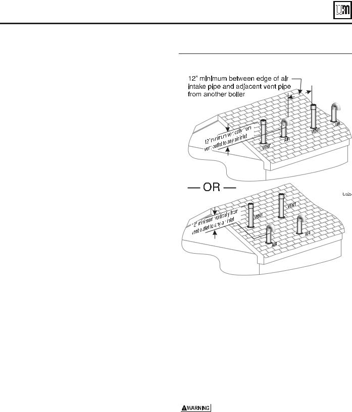
 ® SERIES 4 GAS-FIRED WATER BOILER — Boiler Manual
Vertical vent/air termination: Separate pipes (continued)
5. Maintain clearances to vent termination as given below:
a.Vent must terminate:
ss At least 6 feet from adjacent walls.
ss No closer than 5 feet below roof overhang. ss At least 7 feet above any public walkway.
ssAt least 3 feet above any forced air intake within 10 feet.
ssNo closer than 12 inches below or horizontally from any door or window or any other gravity air inlet.
b.Air inlet must terminate at least 6 inches above the roof or snow line and at least 12 inches below the vent termination as shown in Figure 22, page 23.
c.Do not terminate closer to 4 feet horizontally from any electric meter, gas meter, regulator, relief valve or other equipment. Never terminate above or below any of these within 4 feet horizontally.
6.Locate terminations so they are not likely to be damaged by foreign objects, such as stones or balls, or subject to buildup of leaves or sediment.
7.Do not connect any other appliance to the vent pipe or multiple boilers to a common vent pipe.
Prepare roof penetrations
1.Air pipe penetration:
a.Cut a hole for the air pipe. Size the air pipe hole as close as desired to the air pipe outside diameter.
2.Vent pipe penetration:
a.Cut a hole for the vent pipe. For either combustible or noncombustible construction, size the vent pipe hole at least 0.4” larger than the vent pipe diameter:
ss 2¾” hole for 2”
ss 4” hole for 3”
ss 5” hole for 4”
b. Insert a galvanized metal thimble in the vent pipe hole.
3.Space the air and vent holes to provide the minimum spacings shown in Figure 22, page 23.
4.Follow all local codes for isolation of vent pipe when passing through floors, ceilings and roofs.
5.Provide flashing and sealing boots sized for the vent pipe and air pipe.
Termination and fittings
1.Prepare the vent termination elbow and the air termination elbow (Figure 22, page 23) by inserting bird screens. Bird screens must be purchased separately. See the parts list at the end of this manual for part numbers.
a.If using 3-inch piping for an Ultra-230, cut a 4-inch bird screen by placing 3-inch fitting on screen and cutting around it as a template.
2.The air piping must terminate in a down-turned 180-degree return bend as shown in Figure 22, page 23. Locate the air inlet pipe no further than 2 feet from the center of the vent pipe. This placement avoids recirculation of flue products into the combustion air stream.
24
&IGURE Termination location — separate pipes — terminations for multiple boilers
3.The vent piping must terminate in an up-turned coupling as shown in Figure 22, page 23. The top of the coupling must be at least 1 foot above the air intake. The air inlet pipe and vent pipe can be located in any desired position on the roof, but must always be no further than 2 feet apart and with the vent termination at least 1 foot above the air intake.
4.Maintain the required dimensions of the finished termination piping as shown in Figure 22, page 23.
5.Do not extend exposed vent pipe outside of building more than shown in this document. Condensate could freeze and block vent pipe.
Multiple vent/air terminations (Figure 23)
1.When terminating multiple Ultra boilers, terminate each vent/ air connection as described in this section.
Terminate all vent pipes at the same height and all air pipes at the same height to avoid possibility of severe personal injury, death or substantial property damage.
2.Place roof penetrations to obtain minimum clearance of 12 inches between edge of air intake elbow and adjacent vent pipe of another boiler for U. S. installations (see Figure 2). For Canadian installations, provide clearances required by Natural Gas and Propane Installation CAN/CSA B149.1 or B149.2 Installation Code.
3.The air inlet of an Ultra boiler is part of a direct vent connection. It is not classified as a forced air intake with regard to spacing from adjacent boiler vents.
Part number 550-100-400/0717

 ® SERIES 4 GAS-FIRED WATER BOILER — Boiler Manual
DIRECT VENT
&IGURE DIRECT VENT !00,)#!4)/.3/ |
.6ENTNAND AIRNTERMINATION OPTIONS |
|
|
|
|
|
|
DIRECT VENT |
DIRECT VENT |
DIRECT VENT |
|
VERTICAL vent and |
|||
SIDEWALL termination |
VERTICAL termination |
||
SIDEWALL air |
|||
|
|
7EIL -C,AIN |
|
|
|
6ERTICAL |
SIDEWALL |
|
|
|
|
TERMINATIONN |
|
|
|
VENT |
PLATE |
v ORO v |
|
|
TERMINATION |
3EE "OILER" |
|
|
|
|
CONCENTRIC |
|
|
AND |
|
MANUALA |
TERMINATION |
|
|
|
PAGEE |
|
|
3IDEWALL |
|
|
|
|
||
|
|
|
|
|
|
3EE "OILER" |
|
|
AIR |
|
MANUALA |
"*3 |
|
TERMINATION |
|
PAGEE |
|
7&/5 |
"*3 |
|
|
7&/5 |
||
|
|
|
||
|
|
|
|
3EE "OILER" |
|
|
|
|
MANUALA |
|
|
|
|
PAGEE |
|
|
|
|
6 CX |
|
|
|
|
6 74 CX |
v ORO v |
|
|
|
|
CONCENTRIC |
|
|
|
|
TERMINATION |
|
|
|
|
3EE "OILER" |
|
|
|
|
MANUALA |
|
|
|
|
PAGEE |
|
|
|
|
|
6ERTICALC |
|
|
|
|
TERMINATIONNWITH |
|
|
|
|
SEPARATE VENTT |
|
|
|
|
ANDN |
|
|
|
|
AIRIPIPES |
|
|
|
3IDEWALL |
3EE "OILER" |
|
|
|
TERMINATIONNWITH |
|
|
|
|
MANUALA |
|
|
|
|
SEPARATE VENTT |
|
|
|
|
PAGEE |
|
|
|
|
ANDN |
|
|
|
|
|
|
|
|
|
AIRIPIPES |
|
|
|
|
3EE "OILER" |
|
|
|
|
MANUALA |
|
|
|
|
PAGEE |
|
|
|
|
$IRECT VENTT |
3TEP |
Install the boiler. |
INSTALLATION |
3TEP |
Determine the termination method — sidewall or vertical, concentric or separate pipes, etc. |
SEQUENCE |
3TEP |
Determine proper location for wall or roof penetration for each termination. |
|
||
|
3TEP |
Install termination assembly as described in this manual. |
|
3TEP |
Install air and vent piping from boiler to termination. |
|
3TEP |
Install pipe supports and brackets as required. |
|
|
|
Part number 550-100-400/0717 |
25 |
|
<![endif]>"!3)# ).34!,,!4)/.
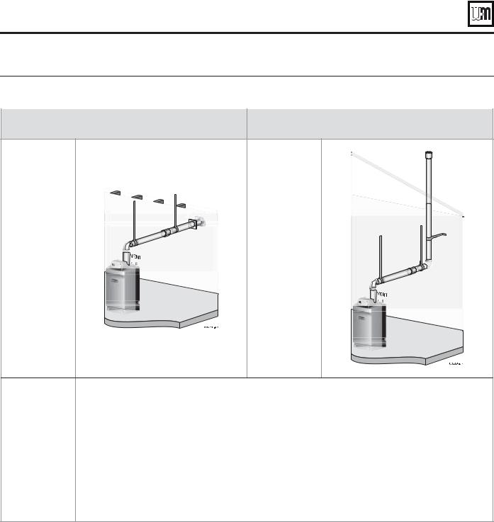
 ® SERIES 4 GAS-FIRED WATER BOILER — Boiler Manual
DIRECT EXHAUST
&IGURE DIRECT EXHAUST !00,)#!4)/.3/ |
.6ENTNTERMINATIONMOPTIONST COMBUSTION AIR FROM ROOM |
||
|
|
|
|
DIRECT EXHAUST |
DIRECT EXHAUST |
||
Sidewall termination |
Vertical termination |
||
|
|
|
|
3IDEWALL VENT |
6ERTICALCVENT |
TERMINATION |
TERMINATION |
3EE "OILER" |
3EE "OILER" |
MANUALAPAGEE |
MANUALAPAGEE |
$IRECT |
3TEP |
|
Install the boiler. |
EXHAUST |
3TEP |
|
Determine the proper location for roof or wall penetration for each termination. |
INSTALLATION |
|
ss Prepare roof penetrations before installing vent piping. |
|
SEQUENCE |
|
ss |
Finish by attaching external pipe and fittings as shown in the termination instructions. |
|
|
ss |
Vertical terminations only — Install terminations as described in this addendum. |
ssSupport vertical runs on the outside of the building with brackets as shown in the termination instructions.
3TEP Install vent piping from boiler to termination.
ss Install a hanger support within 6 inches of any upturn in the piping.
ss Slope horizontal piping downward toward the boiler at least 1/4 inch per foot. 3TEP Connect the vent piping at the boiler per manual instructions.
26 |
Part number 550-100-400/0717 |

 ® SERIES 4 GAS-FIRED WATER BOILER — Boiler Manual
Install condensate line
Prepare condensate fittings
1.Remove PVC fittings and gasket from the accessories bag.
2.Deburr and chamfer outside and inside of ½” x 1¼” PVC nipple to ensure even cement distribution when joining.
3.Clean nipple ends and all fittings. Dry thoroughly.
4.For each joint in the condensate line, apply the following. Assemble parts ONLY in the order given.
a.Apply primer liberally to both joint surfaces — pipe end and fitting socket.
b.While primer is still damp, lightly apply approved cement to both surfaces in a uniform coating.
c.Apply a second coat of cement to both surfaces. Avoid using too much cement on sockets to prevent cement buildup inside.
d.With cement still wet, insert pipe into fitting, twisting ¼ turn. Make sure pipe is fully inserted.
e.Wipe excess cement from joint. Check joint to be sure a smooth bead of cement shows around the entire joint.
5.See Figure 26.
6.Assemble the ½” PVC nipple to the PVC reducing elbow as shown.
7.Allow joint to dry completely.
8.Then slide gasket over nipple as shown in Figure 27.
9.Slide nipple through jacket condensate line hole to position as shown in Figure 27.
10.Cement the ½” tee to the protruding ½” nipple. Be sure both nipple and reducing elbow finish upright.
Firmly press the reducing elbow and the tee together while the cement sets to ensure the gasket is securely compressed. The gasket ensures the jacket enclosure is airtight at this location.
Connect condensate trap line and fittings
1. Remove condensate trap line from bag.
2. 5LTRA ONLY |
FigureY |
28 |
a.Guide the condensate trap line through the bracket hole as shown.
b.Place a hose clamp over the end of the condensate line.
c.Then slide the end of the trap line over the heat exchanger condensate connection.
d.Tighten the hose clamp to secure the trap line.
e.Place a hose clamp over the other end of the condensate trap line.
f.Slide the trap line over the reducing elbow and secure with the hose clamp.
3.Ultra-155 and larger — Figure 30, page 28 or Figure 31, page 28
a.Slide a hose clamp over each end of the condensate trap line.
b.Slide the trap line onto the heat exchanger condensate connection and PVC reducing elbow as shown.
c.Tighten the hose clamps to secure the trap line.
&IGURE Condensate trap assembly
&IGURE #ONDENSATE TRAPAASSEMBLYYINTO JACKET
&IGURE Condensate drain — Ultra-80 & -105
Part number 550-100-400/0717 |
27 |
<![endif]>"!3)# ).34!,,!4)/.
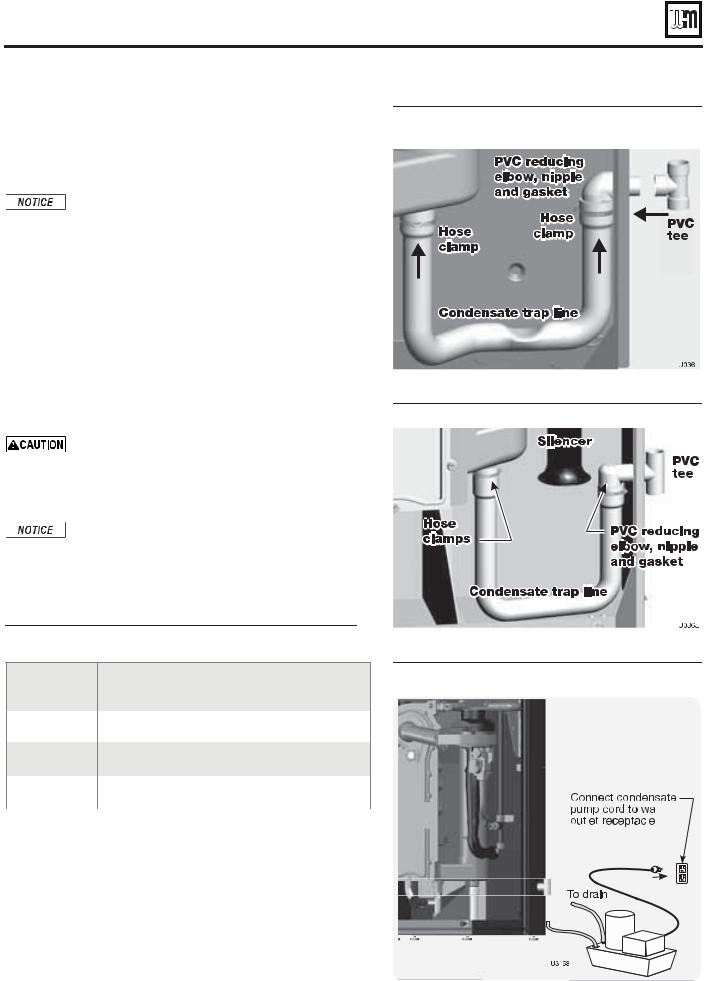
 ® SERIES 4 GAS-FIRED WATER BOILER — Boiler Manual
Install condensate line (continued)
Condensate drain tubing
1.Connect condensate drain tubing to the ½” PVC tee and run to floor drain or condensate pump (see Figure 32). Use ½” PVC or CPVC pipe; or 5/8” I. D. tubing.
Use materials approved by the authority having jurisdiction. In the absence of other authority, PVC and CPVC pipe must comply with ASTM D1785, F441 or D2665. Cement and primer must comply with ASTM D2564, F656, or F493. For Canada, use CSA or ULC certified PVC or CPVC pipe, fittings and cement.
2.Leave the top of the ½” tee OPEN. This is needed as a vacuum break.
3.When installing a condensate pump, select one approved for use with condensing boilers and furnaces. The pump should have an overflow switch to prevent property damage from condensate spillage. See Figure 29 for required flow capacity.
4.When sizing condensate pumps, make sure to include the total load of all Ultra boilers connected to it.
The condensate line must remain unobstructed, allowing free flow of condensate. If condensate is allowed to freeze in the line or if the line is obstructed in any other manor, condensate can exit from the boiler tee, resulting in potential water damage to property.
Condensate from the Ultra boiler will be slightly acidic (typically with a pH from 3.2 to 4.5). Install a neutralizing filter if required by local codes. See Replacement parts section at the end of this manual for the Weil-McLain kit.
&IGURE Condensate drain — Ultra-155 & -230 (PVC tee installation shown applies to all models)
&IGURE Condensate drain — Ultra-299/310 & -399
&IGURE Suggested condensate pump capacity, GPH
Boiler
&IGURE Condensate pump (by others), typical
Minimum recommended condensate pump capacity, per boiler, GPH
Ultra-80 |
2 |
Ultra-230 |
6 |
|
|
|
|
|
|
|
|
|
|
|
|
|
|
|
|
|
|
|
|
|
|
|
|
|
|
|
|
|
|
Ultra-105 |
3 |
Ultra-299/310 |
8 |
|
|
|
|
|
|
|
|
|
|
|
|
|
|
|
|
|
|
|
|
|
|
|
|
|
|
|
|
|
|
Ultra-155 |
4 |
Ultra-399 |
8 |
|
|
|
|
|
|
|
|
|
|
|
|
|
|
|
|
|
|
|
|
|
|
|
|
|
|
|
|
|
|
|
|
|
|
|
|
|
|
|
|
|
|
|
|
|
|
|
|
|
|
|
|
|
|
|
|
|
|
|
|
|
|
|
|
|
|
|
|
|
|
|
|
|
|
|
|
|
|
|
|
|
|
|
|
|
|
|
|
|
|
|
|
|
|
|
|
|
|
|
|
|
|
|
|
|
|
|
|
|
|
|
|
|
|
|
|
|
|
|
|
|
|
|
|
|
|
|
|
|
|
|
|
|
|
|
|
|
|
|
|
|
|
|
|
|
|
|
|
|
|
|
|
|
|
|
|
|
|
|
|
|
|
|
|
|
|
|
|
|
|
|
|
|
|
|
|
|
|
|
|
|
|
|
28 |
Part number 550-100-400/0717 |
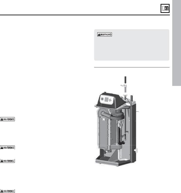
 ® SERIES 4 GAS-FIRED WATER BOILER — Boiler Manual
Gas piping
Connecting gas supply piping
1.Remove jacket front panel and refer to Figure 33 to pipe gas to boiler.
a.Install ground joint union for servicing, when required.
b.Install manual shutoff valve in gas supply piping outside boiler jacket when required by local codes or utility requirements.
c.In Canada — When using manual main shutoff valve, it must be identified by the installer.
2.Wall-mounted boilers
a.Refer to separate Ultra Boiler Wall-mounting instructions.
b.Gas connection may enter from the bottom of boiler as explained in the Wall-mounting instructions.
3.Support piping with hangers, not by boiler or its accessories.
4.Purge all air from gas supply piping.
5.Before placing boiler in operation, check boiler and its gas connection for leaks.
a.Close manual main shutoff valve during any pressure testing at less than 13” w.c.
b.Disconnect boiler and gas valve from gas supply piping during any pressure testing greater than 13” w.c.
Do not check for gas leaks with an open flame — use bubble test. Failure to use bubble test or check for gas leaks can cause severe personal injury, death or substantial property damage.
6.Use pipe dope compatible with propane gases. Apply sparingly only to male threads of pipe joints so that pipe dope does not block gas flow.
Failure to apply pipe dope as detailed above can result in severe personal injury, death or substantial property damage.
DO NOT adjust or attempt to measure gas valve outlet pressure. The gas valve is factory-set for the correct outlet pressure. This setting is suitable for natural gas and propane, requiring no field adjustment. Attempting to alter or measure the gas valve outlet pressure could result in damage to the valve, causing potential severe personal injury, death or substantial property damage.
Ultra boilers are shipped ready to fire natural gas ONLY. (Exception: Ultra-80LP is propane-ready.) You must install the propane orifice if the boiler will be connected to propane. See page 48. Failure to comply could result in severe personal injury, death or substantial property damage.
Gas pipe sizing
1. See page 93 for gas line sizing information.
Check gas pressure at inlet to boiler
1.See Figure 39, page 40, Figure 40, page 40, or Figure 41, page 41 for location of the gas inlet pressure test port.
Use two wrenches when tightening gas piping at boiler, using one wrench to prevent the boiler gas line connection from turning. Failure to support the boiler gas connection pipe to prevent it from turning could damage gas line components.
&IGURE Connect gas supply piping

 5P HBT TVQQMZ
 .BOVBM NBJO HBT
TIVUPGG WBMWF


 (SPVOE KPJOU
VOJPO
#PJMFS HBT DPOOFDUJPO
6
Natural gas supply pressure
1.Pressure required at gas valve inlet pressure port:
a.Maximum: 13” w.c. with no flow (lockup) or with boiler on
b.Minimum: 4” w.c. (for all except 5” for -299/310) with gas flowing (verify during boiler startup, while boiler is at high fire)
2.Install 100% lockup gas pressure regulator in supply line if inlet pressure can exceed 13” w.c. at any time. Adjust lockup regulator for 13” w.c. maximum.
Propane supply pressure
1.Adjust propane supply regulator provided by gas supplier for 13” w.c. maximum pressure.
2.Pressure required at gas valve inlet pressure port:
a.Maximum: 13” w.c. with no flow (lockup) or with boiler on
b.Minimum: 4” w.c. with gas flowing (verify during boiler startup, while boiler is at high fire).
Part number 550-100-400/0717 |
29 |
<![endif]>"!3)# ).34!,,!4)/.
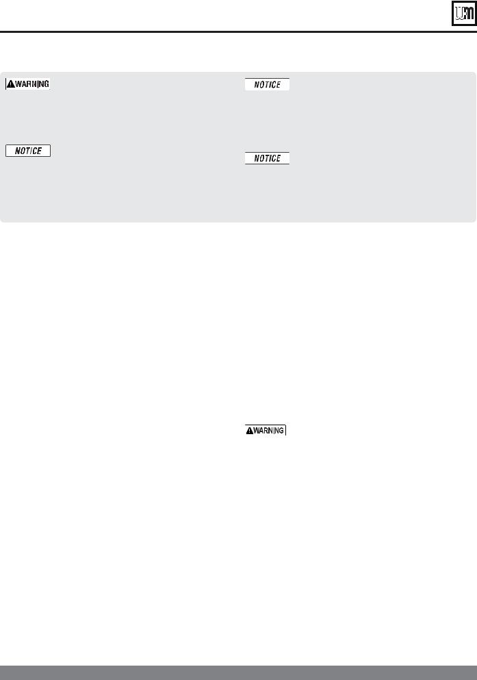
 ® SERIES 4 GAS-FIRED WATER BOILER — Boiler Manual
Field wiring — basic system
%,%#42)#!, 3(/#+/(!:!2$ — For your safety, turn off electrical power supply at service entrance panel before making any electrical connections to avoid possible electric shock hazard. Failure to do so can cause severe personal injury or death.
The installation must comply with: National Electrical
Code and any other national, state, provincial or local codes or regulations. In Canada, CSA C22.1 Canadian Electrical Code Part 1, and any local codes.
Wiring must be N.E.C. Class 1. If original wiring as supplied with boiler must be replaced, use only type 105 °C wire or equivalent. Boiler must be electrically grounded as required by National Electrical Code ANSI/NFPA 70 – latest edition, and/ or the Canadian Electrical Code Part I, CSA C22.1,
Electrical Code.
The boiler when installed, must be electrically bonded to ground in accordance with the requirements of the authority having jurisdiction or, in the absence of such requirements, with the National Electrical Code, ANSI/NFPA 70 – latest edition, and/or the Canadian Electrical Code Part I, CSA C22.1, Electrical Code.
Wiring — general
1.The U-Control provides plug-in, color-coded, noninterchangeable terminal strips for all field wiring. See the schematic diagram (Figure 111, page 96 LADDERDDIAGRAM (Figure 112, page 97).
2.The U-Control provides programmable flexibility in system operation, allowing control of heat supply for up to three different heating systems. Read this manual thoroughly before connecting the wiring to ensure trouble-free start-up and operation.
Wiring — overview
See this and following pages for wiring information. Also see the Advanced section of this manual for additional wiring connections and options.
Make the following connections, some of which depend on your system and how the U-Control will be programmed.
#ONNECTN 6!##POWERE MINIMUM AMP SOURCE
#ONNECTNWIRING FOR UP TO THREE CIRCULATORS
#ONNECTNTHERMOSTATSHAND OR HEATTDEMAND CONTACTS
ssThe U-Control can regulate the boiler for up to three different heating systems.
)NSTALLTSYSTEM OUTDOOR SENSORS WHENHUSED
Line voltage power input
1.Provide and install a fused disconnect or service switch (15-ampere rated recommended) as required by applicable codes.
2.Connect minimum 15-ampere, 120 VAC power wiring to Ultra boiler line voltage terminal strip as shown in Figure 34, page 31, and Figure 111, page 96.
Wiring circulators
1.The U-Control provides for connection of up to three circulators, one of which must be the boiler circulator. In addition, you can connect a system circulator and a DHW circulator, for examples.
4HEHMAXIMUM ALLOWABLE CURRENTRFOR EACH CIRCULATORAIS AMPS AT 6!#. For circulators with higher amp ratings, you must install a circulator relay or starter to provide line voltage to the circulator. For circulators rated over 2.2 amps, connect only the circulator relay or starter coil to the Ultra circulator terminals.
ssThe boiler is shipped with an outdoor sensor, a system supply sensor and a system return sensor. The system supply sensor will be required for most space heating applications. The system return sensor must also be installed when using the system supply sensor. Use of the outdoor sensor is optional.
ssLocate the sensors on the system piping as shown in Figure 4, page 11 and other piping drawings throughout this manual.
3EEEPAGEE !DVANCEDCSECTION FOR OTHER WIRINGROPTIONS
30 |
Part number 550-100-400/0717 |
 Loading...