


GV90+3
®
• Installation
• Startup
• Maintenance
• Parts
Boiler Manual
Gas-Fired W ater Boilers
This manual must only be used by a qualified h eating installer/service technician. BEFORE ins talling, read
all instructions in this manual and all other information shipped with the boiler. Perf orm steps in the order
given. Failure to comply could result in severe personal injury, death or substantial property damage.
Part number 550-142-054/1211

Part number 550-142-054/1211
GV90+ gas-fired water boiler — Boiler Manual
2
1 Integrated boiler control
The integrated boiler control (IBC) responds to signals from the room thermostat, air
pressure switch, inlet water sensor and boiler limit circuit to operate the circulators,
gas valve, igniter and blower. When a room thermostat calls for heat, the IBC starts the
system circulator and blower.
The IBC runs the blower to purge the boiler flue passages, then turns on the igniter and
lets it warm up.
After igniter warm-up, the IBC opens the gas valve, turns the igniter off, and checks for
flame. The flame must come on within 4 seconds or the IBC will shut down and try the
full cycle again.
When the room thermostat is satisfied, the IBC turns off the boiler components and
waits for the next heat call.
The IBC indicator lights show normal sequence when the lights are on steady. When a
problem occurs, the IBC flashes combinations of lights which indicate the most likely
reason for the problem.
2 Transformer
The control transformer reduces line voltage to 24 volts for the gas valve and limit
circuit.
3 Blower
The blower pulls in air and mixes it with gas from the gas valve. The blower forces this
mixture into the burner for combustion inside the boiler chamber.
4 Recuperator
The recuperator is a stainless steel heat exchanger that increases boiler efficiency by ex-
tracting additional heat from the flue gases. Return water passes through the recuperator
before entering the boiler.
5 Water temperature limit switch
The water temperature limit switch turns off the gas valve if the temperature in the
boiler goes above its setting. (The circulators will continue to run as long as there is a
call for heat.)
6 System circulator
The system circulator circulates water through the external (system) piping. The flow
rate of the circulator is controlled by the IBC, depending on the temperature of the water
entering the boiler sections. Pump must remain on boiler — do not remove.
7 Bypass circulator
The IBC operates the bypass circulator to mix hot water from the boiler outlet with
colder return water from the system as needed to prevent condensation of flue gases in
the cast iron heat exchanger.
When the water returning to the boiler is below 140°F, the IBC regulates the bypass cir-
culator and system circulator flow rates to raise the return water temperature up to 140°F
before it enters the cast iron sections. By balancing these flow rates, the IBC can protect
against condensation in the cast iron heat exchanger even if return water is as low as 60°F.
Pump must remain on boiler — do not remove.
8 Air pressure switch
The air pressure switch signals the IBC, telling the control whether air is moving through
the blower.
9 Water temperature sensor
The water temperature sensor monitors the temperature of the water entering the boiler
sections. The sensor sends this information to the IBC. The IBC determines how much
to adjust the circulator flow rates to provide at least 140°F water to the cast iron heat
exchanger.
How it works . . .
LEGEND
a Supply to system, 1” NPT
b Return from system, 1” NPT
c Combustion air inlet fitting —
3” PVC connection
d Flue outlet — 3” PVC connec-
tion
e Gas valve — negative pressure
regulated gas control
f Pressure/temperature gauge
g Flueway inspection port cover
h Sensor hose trap
i Manual air vent
j Relief valve
k Thermal fuse — a one-time fuse
device that shuts boiler off if flue
temperature exceeds its setpoint
m Condensate trap line — shipped
loose with boiler, field installed
n Condensate drain connection —
½” PVC female
This boiler uses a negative-pressure-
regulated gas valve, set for an outlet
pressure approximately –0.20” water
column.
DO NOT set the outlet pressure higher
than factory setting.

Part number 550-142-054/1211
3
GV90+ gas-fired water boiler — Boiler Manual
GV90+ Water Boiler

Part number 550-142-054/1211
GV90+ gas-fired water boiler — Boiler Manual
4
How it works . . . . . . . . . . . . . . 2
GV90+ Water Boiler . . . . . . . . .3
Please read before proceeding . . .5
Prepare boiler location . . . . . . .6
Installations must follow these codes: . . . 6
High altitude installations. . . . . . . . . . 6
Residential garage installation . . . . . . . 7
Check orifice plate — replace if necessary . 8
Install condensate trap. . . . . . . . . . . . 9
Install high altitude air pressure switch when
required (only above 5,550 feet) . . . . . . 9
Rotate the boiler into position . . . . . . 10
Perform hydrostatic pressure test. . . . . 11
Install water piping . . . . . . . . 12
General piping information. . . . . . . . 12
Install relief valve . . . . . . . . . . . . . 12
Expansion tank. . . . . . . . . . . . . . . 13
System water piping methods. . . . . . . 15
Circulators . . . . . . . . . . . . . . . . . 15
Simplified pipe/circulator selection . . . 15
Baseboard system piping — CIRCULATOR
zoning (primary/secondary) . . . . . . . 16
Baseboard system piping — ZONE VALVE
zoning (direct connection) . . . . . . . . 16
Radiator system piping . . . . . . . . . . 18
Single-zone radiant heating or heat pump 19
Adjust balancing valves . . . . . . . . . . 19
Multi-zone radiant heating system . . . . 20
Piping snow melt systems or combination
snow melt/space heating systems . . . . . 21
Water chiller systems . . . . . . . . . . . 22
Multiple boiler installations . . . . 23
Placing multiple boilers . . . . . . . . . . 23
Controlling multiple GV90+ boilers . . . 23
Piping multiple GV90+ boilers . . . . . . 23
Multiple boiler water piping. . . . 24
Easy-Fit® piping installation . . . . . . . 24
Venting & air — general. . . . . . 29
When removing a boiler from an existing
common vent system . . . . . . . . . . . 29
Existing vent test procedure. . . . . . . . 29
Provide combustion air:. . . . . . . . . . 30
Vent and air termination options . . . . . 30
DIRECT VENT installations . . . . . . . 30
DIRECT EXHAUST installations. . . . . 30
Combustion air contamination: . . . . . 30
Manifolded combustion air option for
DIRECT VENT multiple boiler installations
31
Air manifold sizing . . . . . . . . . . . . 31
Commonwealth of Massachusetts
installations . . . . . . . . . . . . 34
Vent termination requirements . . 35
DIRECT VENT — Boiler room air
openings . . . . . . . . . . . . . . 36
DIRECT VENT — Sidewall with W-M
vent/air plate . . . . . . . . . . . . 37
DIRECT VENT — Sidewall with sepa-
rate pipes. . . . . . . . . . . . . . 39
DIRECT VENT — Sidewall with 3”
concentric . . . . . . . . . . . . . 41
DIRECT VENT — Vertical with sepa-
rate pipes. . . . . . . . . . . . . . 43
DIRECT VENT — Vertical with 3”
concentric . . . . . . . . . . . . . 45
Concentric termination assembly
(sidewall or vertical). . . . . . . . 47
Vent and air piping and boiler con-
nections . . . . . . . . . . . . . . 48
DIRECT EXHAUST & DIRECT VENT . 48
Follow termination instructions . . . . . 48
Installing vent and air piping . . . . . . . 48
DIRECT EXHAUST ONLY . . . . . . . . 48
DIRECT EXHAUST — Boiler room air
openings . . . . . . . . . . . . . . 49
Combustion air provision. . . . . . . . . 49
Sizing combustion air openings . . . . . 49
Special considerations . . . . . . . . . . . 49
GV90+ boiler WITHOUT other appliances
in room . . . . . . . . . . . . . . . . . . . 50
Air openings . . . . . . . . . . . . . . . . 50
GV90+ boiler WITH other appliances in
room . . . . . . . . . . . . . . . . . . . . 50
DIRECT EXHAUST — Sidewall . . 51
DIRECT EXHAUST — Vertical . . . 53
Gas piping . . . . . . . . . . . . . 54
Connecting gas supply piping. . . . . . . 54
Natural Gas. . . . . . . . . . . . . . . . . 55
Propane Gas . . . . . . . . . . . . . . . . 55
Wiring . . . . . . . . . . . . . . . 56
Field wiring. . . . . . . . . . . . . . . . . 56
Start-up. . . . . . . . . . . . . . . 59
Freeze protection (when used) . . . . . . 59
Clean system to remove sediment . . . . 59
Water chemistry . . . . . . . . . . . . . . 59
Antifreeze. . . . . . . . . . . . . . . . . . 59
Check for gas leaks. . . . . . . . . . . . . 60
Fill and test water system . . . . . . . . . 60
Verify gas/air orifice plate . . . . . . . . . 61
Check thermostat circuit(s) . . . . . . . . 61
Inspect/fill condensate system . . . . . . 61
Final checks before starting boiler . . . . 62
To start the boiler . . . . . . . . . . . . . 62
If boiler does not start correctly . . . . . 62
Check system and boiler after start-up. . 62
Gas valve adjustment — altitude over 5,500
feet ONLY . . . . . . . . . . . . . . . . . 62
Final checklist . . . . . . . . . . . . . . . 64
Annual start-up and general mainte-
nance schedule . . . . . . . . . . 67
Annual start-up . . . . . . . . . . 68
Address reported problems . . . . . . . . 68
Inspect boiler area . . . . . . . . . . . . . 68
Inspect boiler interior . . . . . . . . . . . 68
Inspect condensate drain system . . . . . 68
Inspect all piping for leaks . . . . . . . . 68
Inspect gas piping . . . . . . . . . . . . . 68
Inspect the water system. . . . . . . . . . 68
Inspect expansion tank . . . . . . . . . . 68
Inspect air openings . . . . . . . . . . . . 69
Inspect vent system and air piping . . . . 69
Inspect boiler heating surfaces . . . . . . 69
Inspect recuperator . . . . . . . . . . . . 69
Inspect igniter . . . . . . . . . . . . . . . 69
Inspect temperature mixing system . . . 70
Inspect limit controls and cutoffs. . . . . 70
Inspect gauges . . . . . . . . . . . . . . . 70
Inspect blower motor . . . . . . . . . . . 70
Inspect oiled-bearing circulators . . . . . 70
Inspect boiler relief valve . . . . . . . . . 71
To complete Annual Start-up, perform
startup and checks: . . . . . . . . . . . . 71
Review with owner. . . . . . . . . . . . . 71
Service & maintenance . . . . . . 72
Cleaning boiler heating surfaces . . . . . 72
Inspecting and cleaning the recuperator . 73
Troubleshooting . . . . . . . . . . 75
VERIFY PROPER OPERATION AFTER
SERVICING. . . . . . . . . . . . . . . . . 75
Before troubleshooting . . . . . . . . . . 75
Check the following . . . . . . . . . . . . 75
Checking the air pressure switch . . . . . 75
Igniter. . . . . . . . . . . . . . . . . . . . 76
Gas Valve . . . . . . . . . . . . . . . . . . 76
Blower Housing . . . . . . . . . . . . . . 76
Thermal fuse . . . . . . . . . . . . . . . . 76
Return temperature sensor . . . . . . . . 76
IBC (integrated boiler control)
. . . . . . 77
IBC indicator lights — lockout modes . . 77
IBC indicator lights — non-lockout modes
77
Replacement parts . . . . . . . . 89
Dimensions and ratings. . . . . 100
NOTES . . . . . . . . . . . . . . 104
NOTES . . . . . . . . . . . . . . 106
Handling ceramic ber and ber-
glass materials. . . . . . . . . . 107
Installation and service
certicate . . . . . . . . . . . . 108
Contents

Part number 550-142-054/1211
5
GV90+ gas-fired water boiler — Boiler Manual
Failure to adhere to the guidelines on this
page can result in severe personal injury,
death or substantial property damage.
When servicing boiler —
• To avoid electric shock, disconnect electrical supply
before performing maintenance.
• To avoid severe burns, allow boiler to cool before
performing maintenance.
• This boiler contains ceramic fiber and fiberglass
materials. Refer to the WARNING and instructions
on page 107.
Boiler operation —
• Do not block flow of combustion or ventilation air
to boiler.
•
Should overheating occur or gas supply fail to
shut off, DO NOT turn off or disconnect electrical
supply to circulator. Instead, shut off the gas supply
at a location external to the appliance.
•
Do not use this boiler if any part has been under
water. Immediately call a qualified service techni-
cian to inspect the boiler and to replace any part of
the control system and any gas control that has been
under water.
Combustion air —
• DO NOT install combustion air intake where there
is a risk of combustion air contamination.
Carbon monoxide detector —
• For Direct Exhaust units, a carbon monoxide detec-
tor is required in the boiler room. The carbon mon-
oxide detector must be wired on the same electrical
circuit as the boiler.
• For
Direct Vent units, a carbon monoxide detector
that is wired on the same electrical circuit as the boiler
is strongly recommended.
Boiler water —
• Thoroughly flush the system (without boiler con-
nected) to remove sediment. The high-efficiency heat
exchanger can be damaged by build-up or corrosion
due to sediment.
• Do not use petroleum-based cleaning or sealing
compounds in boiler system. Gaskets and seals in the
system may be damaged. This can result in substantial
property damage.
•
Leaks in boiler or piping must be repaired at once
to prevent make-up water. Use this boiler ONLY
in a closed-loop system. Continual fresh make-up
water will reduce boiler life. Mineral buildup in heat
exchangers reduces heat transfer, overheats the mate-
rials, and causes failure. Addition of oxygen carried in
by make-up water can cause internal corrosion.
•
Do not add cold water to hot boiler. Thermal shock
can cause heat exchanger to crack.
Freeze protection uids —
• NEVER use automotive or standard glycol antifreeze.
Use only freeze-protection fluids made for hydronic
systems. Follow all guidelines given by the antifreeze
manufacturer. Thoroughly clean and flush any re-
placement boiler system that has used glycol before
installing the new boiler.
Please read before proceeding
Installer— Read all instructions, including this
manual and all other information shipped with the
boiler, before installing. Perform steps in the order
given.
User — This manual is for use only by a qualified
heating installer/service technician. Refer to User’s
Information Manual for your reference.
User — Have this boiler serviced/inspected by a
qualified service technician, at least annually.
Failure to comply with the above could result in
severe personal injury, death or substantial property
damage.
Write in the CP number in the space provided on
the Installation certificate on page 108 if not already
shown.
When calling or writing about the boiler— Please
have the boiler model number from the boiler rating
label and the CP number from the boiler jacket.
Consider piping and installation when determining
boiler location.
Any claims for damage or shortage in shipment
must be filed immediately against the transportation
company by the consignee.
Commonwealth of Massachusetts
When the boiler is installed within the Commonwealth of Mas-
sachusetts, comply with the following.
• This product must be installed by a licensed plumber or gas
fitter.
• If antifreeze is used, a reduced pressure back-flow preventer
device shall be used.
• If sidewall vent or vent/air is installed, see instructions on
page 34.
Hazard denitions
The following defined terms are used throughout this manual to
bring attention to the presence of hazards of various risk levels or
to important information concerning the life of the product.
Indicates presence of hazards that will cause severe
personal injury, death or substantial property dam-
age.
Indicates presence of hazards that can cause severe
personal injury, death or substantial property dam-
age.
Indicates presence of hazards that will or can cause
minor personal injury or property damage.
Indicates special instructions on installation, op-
eration or maintenance that are important but not
related to personal injury or property damage.
Part number 550-142-054/1211
GV90+ gas-fired water boiler — Boiler Manual
6
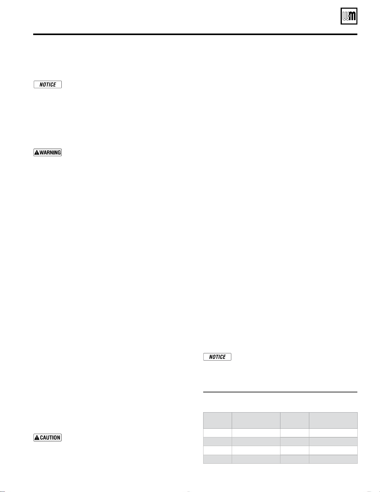
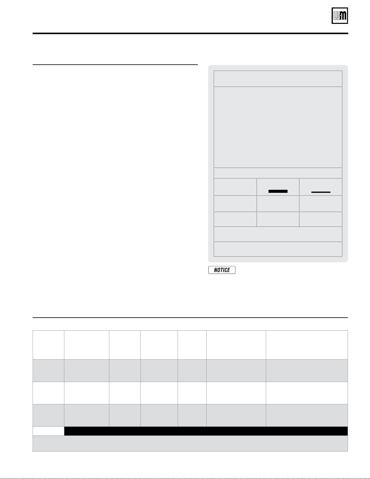
Figure 1 Estimated GV90+ input at altitude
Altitude
(feet)
% Sea level input
1,000 97
2,000 93
3,000 90
4,000 87
5,000 83
5,500 82
6,000 80
7,000 77
8,000 74
9,000 72
10,000 69
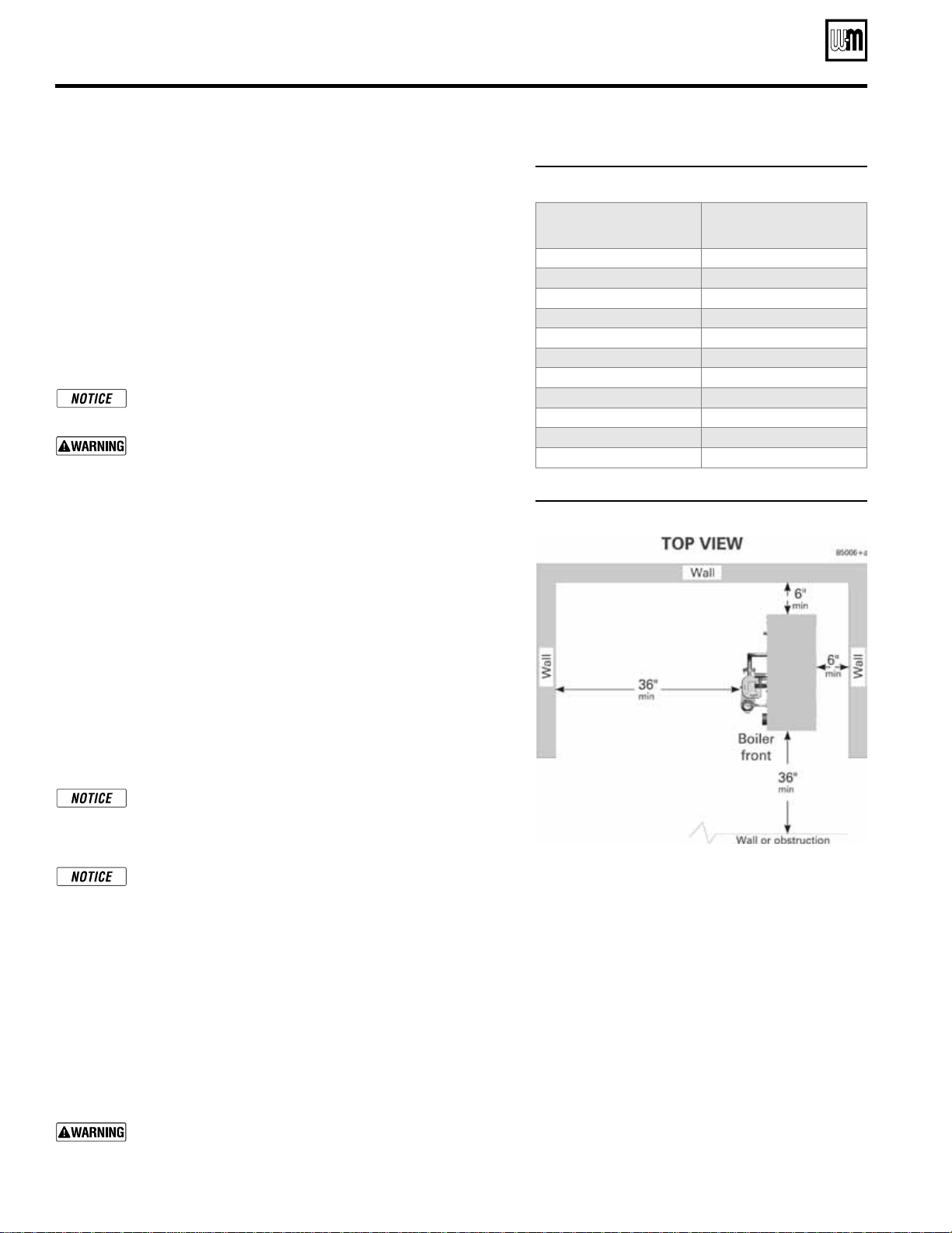
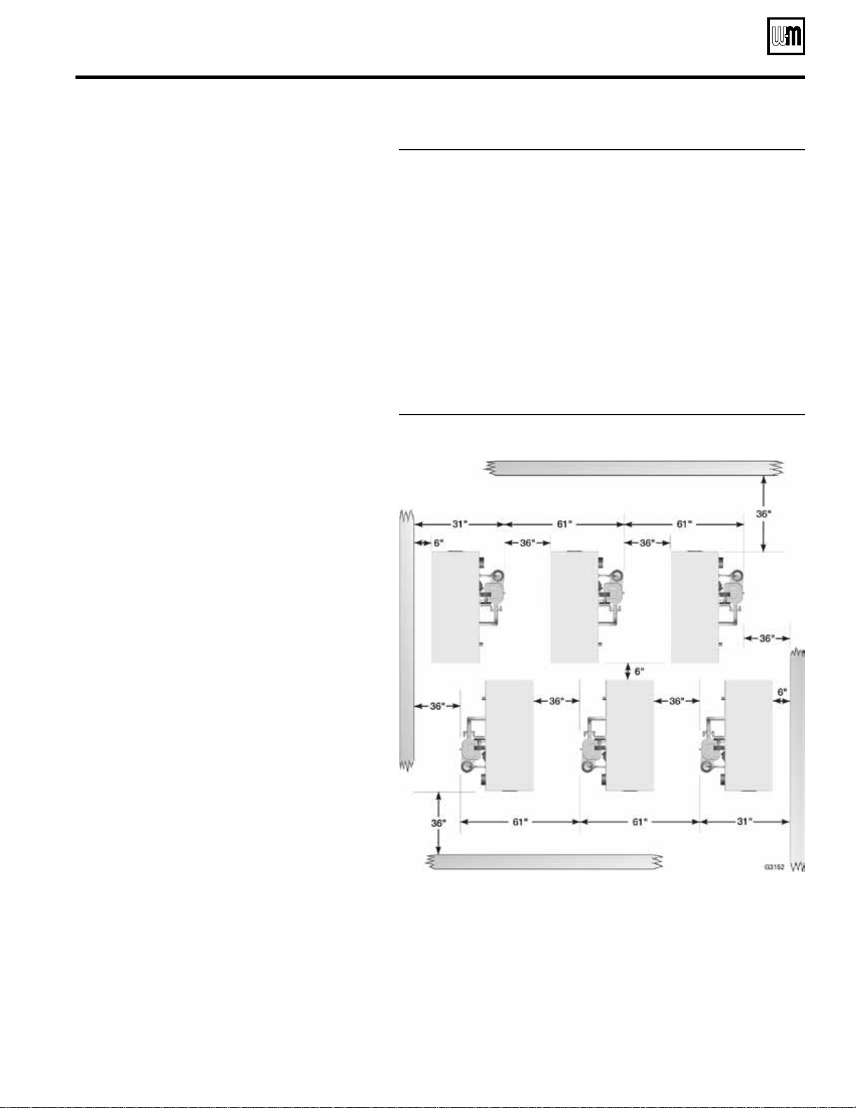
Figure 2 Service clearances (recommended)
Prepare boiler location
Installations must follow these codes:
• Local, state, provincial, national codes, laws, regulations and ordinances.
• NationalFuelGasCode,ANSIZ223.1-latestedition.
• StandardforControlsandSafetyDevicesforAutomaticallyFiredBoil-
ers, ANSI/ASME CSD-1, when required.
• NationalElectricalCode.
• ForCanadaonly:B149.1orB149.2InstallationCodeandCSAC22.1
Canadian Electrical Code Part 1 and any local codes.
The GV90+ boiler gas manifold and controls met safe lighting and other
performance criteria when boiler underwent tests specified in ANSI Z21.13
— latest edition.
For the Commonwealth of Massachusetts, read and follow
the special instructions located on page 34 of this manual.
Install the boiler so control system components are protected
from dripping or spraying water or rain
during operation.
Allowing these components to become wet could cause a
boiler failure, resulting in severe personal injury, death or
substantial property damage.
High altitude installations
GV90+ boiler controls automatically reduce input with increasing altitude.
See Figure 1 for estimated input at altitude as a percentage of sea level
input. Multiply the boiler sea level input by this percentage to obtain the
estimated high altitude input. Note that the length of the venting system
will also have a minor impact on input. Refer to the vent supplement for
further information.
No modifications to the boiler should be necessary for installations up to
5,500 feet above sea level. For higher elevations, the air pressure switch
must be changed to a special high altitude switch. Refer to the high altitude
kit instructions, page 10. Note that the gas valve outlet pressure must be
checked (and adjusted if necessary) following instructions on page 62.
DO NOT sidewall vent DIRECT EXHAUST APPLICATIONS
at altitudes above 5,500 feet. Sidewall venting is only allowed
for DIRECT VENT applications (ducted combustion air) at
altitudes above 5,500 feet.
Vent length also affects boiler input — the boiler automati-
cally derates to compensate for pressure loss through the vent.
See the derate values given in Figure 109, page 101. For high
altitude installations, multiply the % in Figure 1 times the
value shown in Figure 109 to determine input vs sea level.
Service clearances
When possible, install GV90+ boilers with clearances at least as large as
shown in Figure 2 for best service access.
Flooring
The GV90+ boiler is approved for installation on combustible flooring,
but must never be installed on carpeting.
Do not install boiler on carpeting even if foundation is used.
Fire can result, causing severe personal injury, death or sub-
stantial property damage.
Part number 550-142-054/1211
7
GV90+ gas-fired water boiler — Boiler Manual
Foundation
Provide a solid brick or concrete foundation pad if any of the following
is possible:
• When the floor can become flooded.
• When the boiler mounting area is not level.
• When a high-profile condensate pump is used, provide a foundation
high enough that the GV90+ condensate connection is at least as high
as the condensate pump inlet connection.
Figure 3
Minimum foundation dimensions (inches)
Boiler model W L H *
GV90+3 / GV90+4 16 30¾ 2
GV90+5 / GV90+6 16 37¾ 2
* Increase height if needed to ensure
condensate trap outlet tee is above inlet
of condensate pump, when used.
Residential garage installation
Precautions
Take the following special precautions when installing the boiler in a
residential garage. If the boiler is located in a residential garage, per ANSI
Z223.1, paragraph 5.1.9:
• Mount the boiler a minimum of 18 inches above the oor of the
garage to assure the burner and ignition devices will be no less than
18 inches above the floor.
• Locate or protect the boiler so it cannot be damaged by a moving
vehicle.
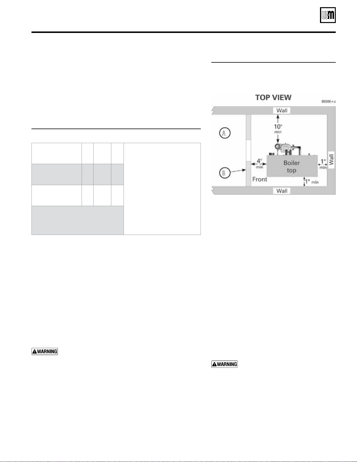
Minimum clearances
You can install GV90+ boilers in spaces smaller than Fig-
ure 2, page 6 recommended service clearances, but never
smaller than shown in Figure 4.
Installations with clearances less than shown in Fig-
ure 2, page 6 must have air openings sized and located as
shown in Figure 4.
• Always provide at least screwdriver clearance to jacket front panel screws
for removal of front panel for inspection and minor service.
• If the boiler cannot be serviced in place, pipe the boiler with unions
and isolation valves so it can be slid out of the space and serviced in
an adjacent area.
• The space has to be equipped with a door so boiler can be accessed,
unpiped and removed.
Prepare boiler location (continued)
Figure 4 Minimum clearances — when
clearances are less than recom-
mended service clearances of Fig-
ure 2, page 6, install as shown below:
A Area adjacent to access door must be accessible
and must allow for removal of the GV90+boiler
for service.
No other appliance or air mover (exhaust fan,
etc.) may be mounted in the same space.
B Access DOOR with fresh air openings
C Provide (2) Fresh air openings — Each with at
least 1 sq. inch per 1,000 Btuh of boiler input
NOTICE SPECIAL REQUIREMENTS
FOR AIR OPENINGS
: For installations
with clearances less than recommended
service clearances (Figure 2, page 6), but
no less than shown in Figure 4 — An
access door must be provided, fitted with
two air openings as shown in Figure 4.
Each opening must have a free area no
less than 1 square inch per 1000 Btuh
input of the GV90+ boiler in the space.
DO NOT apply the air opening sizes
given in Figure 42, page 36 or Fig-
ure 60, page 50
.
Part number 550-142-054/1211
GV90+ gas-fired water boiler — Boiler Manual
8
Prepare the boiler (continued)
Check orifice plate — replace if necessary
The correct orice plate must be used. Failure to do so
will result in severe personal injury, death or substantial
property damage. The boiler is shipped with a natural
gas orice plate. It MUST BE CONVERTED to use
propane.
Natural gas:
For natural gas installations, inspect the silver gas/air orice plate
marking
. It must be the same as the boiler size. If the orifice plate is
stamped with another size, obtain the correct plate from your whole-
saler. The boiler size is stamped where the “X” is shown in the plate
stamping, Figure 6.
Propane:
For propane installations, replace the silver gas/air orice plate
with the red/white plate
, per following instructions. Ensure the red/
white plate boiler size is correct for the GV90+ boiler being installed.
The boiler size is stamped where the “X” is shown in the plate stamp-
ing, Figure 6.
Also fill out the propane label in the conversion kit and attach to the
left side of the jacket, above the gas inlet opening, as shown in Figure 5.
Orice plate installation, when required
Access the bottom of the blower housing as shown in Figure 5.
To inspect the plate only,
read the marking on the plate edge. It
must read the same as the boiler size and fuel, as follows:
Boiler model Natural gas marking Propane marking
GV90+3 NG 3 SEC LP 3 SEC
GV90+4 NG 4 SEC LP 4 SEC
GV90+5 NG 5 SEC LP 5 SEC
GV90+6 NG 6 SEC LP 6 SEC
To replace the plate, using a manual screwdriver or nut driver, see
Figure 6:
1. Loosen screws
1 and 2 two full turns.
2. Remove screws
3 and 4.
3. Pull the gas/air orifice plate forward to remove it.
4. Slide in the new plate as shown in Figure 6. The
red side of a
propane plate must go next to the blower housing
.
5. Replace screws
3 and 4. Tighten all four screws securely and uni-
formly. DO NOT overtighten. DO NOT exceed 40 inch-pounds
torque.
6. Bend down plate label tab at score mark as shown in lower right
corner of Figure 6, item 10.
DO NOT use electric or pneumatic screwdrivers to re-
move or tighten the gas/air boss screws. Hand-tighten
only, using manual screwdriver. Should the torque exceed
40 inch-pounds, the threaded holes could strip out,
causing an inadequate seal of the orifice plate. Failure to
properly seal the plate to the housing could result in a gas
leak, causing severe personal injury, death or substantial
property damage.
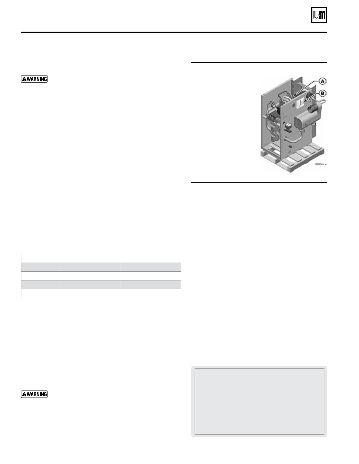
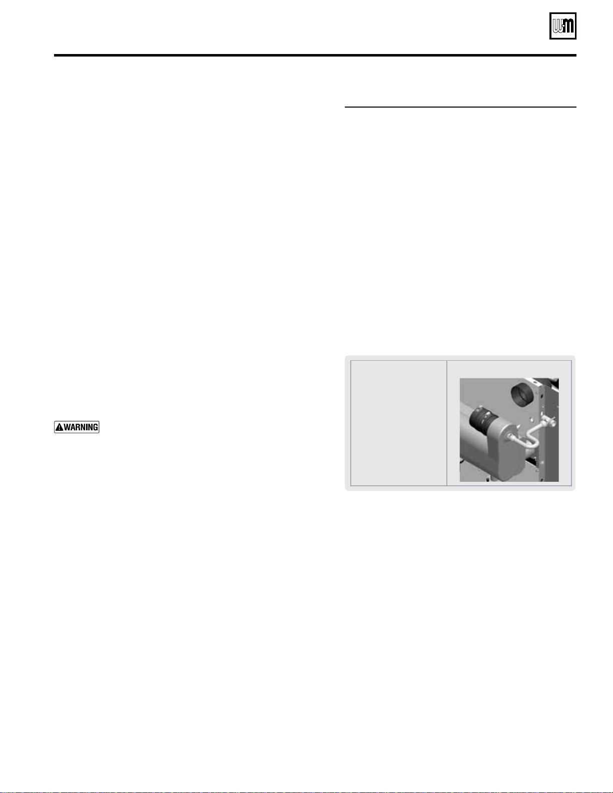
Figure 5 Check for correct gas orifice plate
A Remove jacket front
panel to access the bot-
tom side of the blower
housing.
B Complete the propane
conversion label includ-
ed with the conversion
kit. Install label on jacket
left side, as shown.
Leave the boiler on its back,
on the skid as shown, until
you have checked the gas/air
orifice plate and replace it if
necessary.
Figure 6 Follow instructions to check or replace
gas orifice plate ("X" = boiler size)
1–4 Screws — follow instructions for loosening and tightening
5 Gas/air manifold
6 Front section, bottom view, component details omitted
7 Side shown must point toward air inlet hose — WARNING
label side for natural gas; WHITE side for propane gas
8 Propane orifice plate, RED one side and WHITE on the
other (red side must face the blower housing
9 Natural gas orifice plate, SILVER
10 Orifice plate after bending along score mark — label is
visible when installed
Part number 550-142-054/1211
9
GV90+ gas-fired water boiler — Boiler Manual
Prepare the boiler (continued)
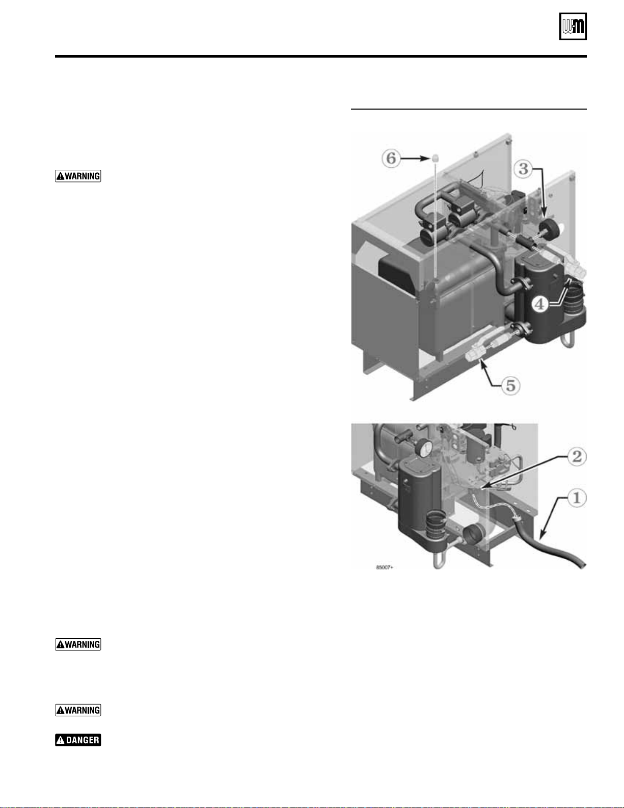
Figure 7 Install condensate trap
A In-line flue drain
B Flue drain nipple
C Flue drain hose
D Flue connection
E Condensate trap tee
F U-clamp and nuts (not
shown)
G Condensate drain
nipple
H Condensate trap hose
J Hose clamps
Finished assembly
Install condensate trap
1. Before placing the boiler in position, install the condensate trap
line, shown in Figure 7. Items shown are provided with the boiler.
Step 1 Attach the flue drain hose (C) to the in-line flue drain
nipple (B).
Step 2 Slide a screw driver or pencil through the condensate
drain nipple (G).
Slide the end of the screwdriver or pencil into the open
end of the flue drain hose (C).
Feed the in-line flue drain (A) assembly into the flue con-
nection (D), guiding the flue drain hose through the con-
densate drain nipple (G) with the screwdriver or pencil.
Step 3 Press the in-line flue drain (A) into the flue connection
(D) and through the seal ring until it reaches the stop.
Then tighten the flue connection hose clamp to secure.
The flue drain hose (C) should now extend down past the
end of the condensate drain nipple (G).
Step 4 Slide the U-clamp (F) over the condensate trap tee (E)
and into the two holes in the rail. Attach the two nuts pro-
vided to the U-clamp and tighten to secure the condensate
trap tee to the rail.
Step 5 Slide the ends of the condensate trap hose (H) onto the
condensate drain nipple (G) and the condensate trap tee
(E). Secure the condensate trap hose at each end with the
hose clamps (J).
Check the height of the condensate trap tee outlet.
Before rotating the boiler into position, measure the
distance from the condensate tee outlet to the bottom
of the boiler mounting rails. When the boiler is place in
position, the condensate tee outlet must be higher than
the condensate pump inlet connection (when a con-
densate pump is used). Increase the foundation height
if necessary.
Part number 550-142-054/1211
GV90+ gas-fired water boiler — Boiler Manual
10
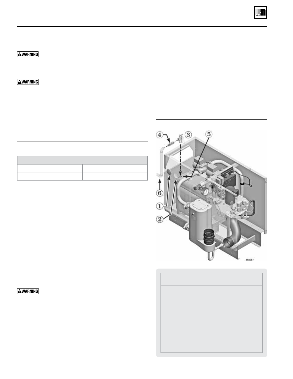
Figure 8 Air pressure switch mounting
1 Interior panel top
2 Jacket left side panel
3 Air pressure switch
4 WHITE hose
5 RED hose
6 Mounting screws
Figure 9 Follow instructions to perform the steps
shown below
Prepare the boiler (continued)
Install high altitude air pressure switch
when required (only above 5,500 feet)
1. For installations at altitude more than 5,500 feet above sea level:
a. A special high altitude air pressure switch is required.
b. The gas valve outlet pressure setting must be checked, and
adjusted if necessary, per the instructions on page 62.
Failure to check gas valve outlet pressure and adjust, if
necessary, could result in severe personal injury, death
or substantial property damage. Carefully follow the
guidelines given in this manual.
2. Obtain the GV90+ high altitude kit from your local Weil-McLain
distributor. The high altitude kit contains the high altitude air
pressure switch.
3. See Figure 8 (switch shown with wires removed).
a. Remove the two (RED) control wires from the air pressure
switch spade terminals.
b. Remove the factory-installed air pressure switch (loosen top
screw and remove bottom screw holding switch to jacket in-
terior panel).
c. Install the high altitude air pressure switch in the same loca-
tion.
d. Carefully replace the hoses on the new switch, with the red hose
on the hose barb closest to the electrical spade connectors, as
shown in Figure 8. The white hose goes on the other hose barb.
e. Replace the two (RED) control wires on the new pressure
switch spade terminals.
Rotate the boiler into position
Boiler is shipped on back side. It must be taken off skid
and rotated into correct position.
After installing condensate line, inspecting (replacing if necessary) the
gas/air orifice and installing the high altitude kit (if required), move
the boiler near its position.
Figure 9 shows the boiler with the front and top panels replaced.
These panels may be left off if desired until the installation has been
completed.
Boiler is heavy and contains some sheet metal parts which
may have sharp edges. Wear gloves when handling and
take proper precautions when moving. Failure to do so
will result in severe personal injury, death or substantial
property damage.
Refer to Figure 9 for placement sequence as follows:
1 Wear heavy gloves — carefully rotate the boiler over onto its
base rail legs.
2 Clip the shipping strap securing the skid to the boiler block as-
sembly. Remove the skid and strap.
3 Attach the jacket rear panel as shown using (4) #10 x ½” screws
provided in the accessory bag.
Part number 550-142-054/1211
11
GV90+ gas-fired water boiler — Boiler Manual
Figure 10 Piping connections for hydrostatic test
Perform hydrostatic pressure test
Pressure test boiler before attaching water or gas piping (except as
noted below) or electrical supply. Remove jacket top panel before
proceeding.
Use two wrenches when tightening water piping at
boiler
, using one of the wrenches to prevent the boiler
interior piping from turning. Failure to support the boiler
piping connections to prevent them from turning could
cause damage to boiler components.
Prepare boiler for test — see Figure 10
Step 1 Connect a hose from water supply to fill and drain boiler
for hydrostatic test. Hose is not included with boiler.
Step 2 Connect hose to boiler drain valve. Make sure hose can
also be used to drain boiler after test.
Step 3 Remove 1" nipple, 1" tee, bushing and pressure/tempera-
ture gauge from accessory bag. Pipe to boiler supply con-
nection as shown. Use pipe dope sparingly.
Step 4 Connect a nipple and shutoff valve to system supply
connection on the 1" tee. This valve will be used to bleed
air during the fill. Valve and nipple are not included with
boiler.
Step 5 Connect a nipple and shutoff valve to system return
connection at circulator flange. This valve will be used to
bleed air during the fill. Valve and nipple are not included
with boiler.
Step 6 Install a ¾" pipe plug in the relief valve opening, top of
the rear boiler section, as shown. Plug is not included with
boiler.
Fill and pressure test
1. Connect fill water supply through drain valve, item 2.
2. Fill boiler with water (be sure bleed valves at 4 and 5 are open).
3. When water flows from bleed valves, shut off water at drain
valve.
4. Close bleed valves.
5. Slowly reopen drain valve (item 2) until test pressure of 45 PSIG
(or 1.5 times boiler relief valve setting — NEVER MORE than
75 PSIG) is reached on the pressure gauge.
6. Test at this pressure for no more than 10 minutes.
Do not leave boiler unattended. A cold water fill could
expand and cause excessive pressure, resulting in severe
personal injury, death or substantial property damage.
7. Make sure constant gauge pressure has been maintained through-
out test. Check for leaks. Repair if found.
Leaks must be repaired at once. Failure to do so can dam-
age boiler, resulting in substantial property damage.
Do not use petroleum-based cleaning or sealing com-
pounds in boiler system. Severe damage to boiler will
occur, resulting in substantial property damage.
Drain and remove ttings
1. Disconnect fill water hose from water source.
2. Drain boiler at drain valve or out hose, whichever pro-
vides best access to drain. Close drain valve and remove
hose after draining.
3. Remove nipples and valves at 4 and 5 unless they will
remain for use in the system piping.
4. Remove plug (item 6) from relief valve tapping.
Prepare the boiler (continued)
Part number 550-142-054/1211
GV90+ gas-fired water boiler — Boiler Manual
12
Install water piping
Air separator
Install an air separator in the piping as shown in this
manual. For single-zone systems, install the air separator
in the return piping as shown in Figure 14, page 14. This
allows mounting the automatic air vent and expansion tank
off of the separator.
Install relief valve
1. Install relief valve ONLY as shown in Figure 12.
2. Connect discharge piping to safe disposal location, fol-
lowing guidelines in Figure 13, page 13.
Figure 12
Install and pipe relief valve
Legend
1 Jacket plug for unused relief valve jacket open-
ing.
2 Jackets are provided with two relief valve open-
ings because each jacket size is used for two boiler
sizes. Cover the unused opening with the plug
provided.
3 Boiler relief valve (from accessory bag)
4 ¾” x 3” nipple, provided in accessory bag
5 ¾” relief valve tapping in back section
6 Connect minimum ¾” discharge piping to relief
valve.
See Figure 13, page 13.
Use two wrenches when tightening water piping at
boiler
, using one of the wrenches to prevent the boiler
interior piping from turning. Failure to support the boiler
piping connections to prevent them from turning could
cause damage to boiler components.
The cast iron heat exchanger return temperature must
be kept at or above 140°F during all times of operation
to prevent possibility of corrosion due to condensation.
This is done automatically, using the boiler's internal
circulators. DO NOT remove or tamper with these cir-
culators. Failure to comply could result in severe personal
injury, death or substantial property damage.
General piping information
Minimum pipe size for boiler loop piping
Figure 11 Provide boiler loop piping no smaller than listed
below (based on 20°F temperature rise)
Boiler loop pipe size, Minimum
GV90+3 or 4 1”
GV90+5 or 6 1¼”
Additional limit controls
Following standard industry practices, if installation is to comply with
ASME or Canadian requirements, an additional high temperature
limit
may be needed. Consult local requirements for other codes/
standards to determine if needed. Wire as shown in Figure 67, page 56.
• Install a manual reset high temperature limit between the boiler
and the isolation valve.
• Wire the manual reset limit in series with the boiler limit con-
trol.
• Set the manual reset limit control at least 20°F above the boiler
limit control setting (maximum setting 220°F).
Low water cut-off, when required
A low water cutoff device is required when boiler is installed above
radiation level or by certain state or local codes or insurance companies.
Use low water cutoff designed for water installations. Electrode probe-
type is recommended. Purchase and install in tee in supply piping above
boiler. Wire contact as shown in Figure 67, page 56.
If boiler is connected to heating coils located in air han-
dling units where they can be exposed to refrigerated
air, use flow control valves or other automatic means to
prevent gravity circulation during cooling cycle. Circu-
lation of cold water through the boiler could result in
damage to the heat exchanger, causing possible severe
personal injury, death or substantial property damage.
Backow preventer
Where required by codes, install a backow preventer in the cold
water fill line, as shown in suggested piping diagrams on following
pages. Install a check valve if a backflow preventer is not installed.
Part number 550-142-054/1211
13
GV90+ gas-fired water boiler — Boiler Manual
Install water piping (continued)
Figure 13 Relief valve installation guidelines
To avoid water damage or scalding
due to relief valve operation, as
per local or state codes
:
Discharge line must be connected
to relief valve outlet and run to a
safe place of disposal. Terminate the
discharge line in a manner that will
prevent possibility of severe burns
or property damage should the valve
discharge.
Discharge line must be as short as
possible and be the same size as the
valve discharge connection through-
out its entire length.
Discharge line must pitch downward
from the valve and terminate at least
6” above the floor drain where any
discharge will be clearly visible.
The discharge line shall terminate
plain, not threaded, with a mate-
rial serviceable for temperatures of
375°F or greater.
Do not pipe the discharge to any
place where freezing could occur.
No shutoff valve shall be installed
between the relief valve and boiler,
or in the discharge line. Do not
plug or place any obstruction in the
discharge line.
Test the operation of the valve after
filling and pressurizing system by
lifting the lever. Make sure the valve
discharges freely. If the valve fails to
operate correctly, replace it with a
new relief valve.
Failure to comply with the above
guidelines could result in failure of
the relief valve to operate, resulting
in possibility of severe personal in-
jury, death or substantial property
damage.
Expansion tank
Figure 14, page 14 and Figure 15, page 14 show typical installation of the
expansion tank. Always locate the air separator and expansion tank as
shown in the suggested piping drawings, beginning with Figure 17, page 16.
Ensure that the expansion tank size will handle boiler and system water
volume and temperature. See tank manufacturer’s instructions and rat-
ings for details. Additional tanks may be added to the system if needed to
handle the expansion. These tanks may be installed by connecting to tees
in the system piping.
Undersized expansion tanks cause system water to be lost
from the relief valve and makeup water to be added through
the fill valve. Eventual section failure can result. Always locate
the cold water ll connection at the expansion tank. Never
locate this elsewhere in the system.
Diaphragm- or bladder-type tank:
Refer to Figure 14, page 14 for suggested piping when using a diaphragm-
or bladder-type expansion tank.
Diaphragm- or bladder-type expansion tank — Control
ll pressure with the tank air charge pressure. Always check
pressure and charge tank with tank removed fr om system
to be sure reading is accurate. Boiler relief valve is set for 30
PSIG. Operating pressure of system, after temperature expan-
sion above cold fill pressure, should not exceed 24 PSIG to
avoid weeping of relief valve.
Install an
automatic air vent on top of the air separator, per separator
manufacturer’s instructions.
Closed-type expansion tank:
Figure 15, page 14 shows suggested piping when using a closed-type expan-
sion tank, in which the air is directly in contact with tank water.
Connect piping (½” or ¾”) from the air separator top outlet to the tank
fitting. Slope any horizontal piping a minimum of 1 inch per 5 feet of
horizontal pipe.
Always use a
tank tting, such as the B&G Tanktrol or Taco Taco-Trol
(shown). The fitting reduces gravity flow of water in the piping to the
tank, avoids air bubbling through the tank water, and provides the proper
fill height in the tank.
Correct all leaks in the system or tank piping. Leaks allow
air to escape from the system and will cause water-logging
of the tank. This will result in water loss through the boiler
relief valve due to over-pressurization.
NEVER use an automatic air vent in a system equipped with a
closed-type expansion tank. The air removed from the system
will cause water-logging of the expansion tank.
Closed-type expansion tank — Follow tank manufacturer’s
instructions for lling the tank. Typical tank sizing provides
for approximately 12 PSIG when the tank is filled to the
normal level and system water is cold. Note that boiler relief
valve is set for 30 PSIG. Operating pressure of system, after
temperature expansion above cold fill pressure, should not
exceed 24 PSIG to avoid weeping of relief valve.
Part number 550-142-054/1211
GV90+ gas-fired water boiler — Boiler Manual
14
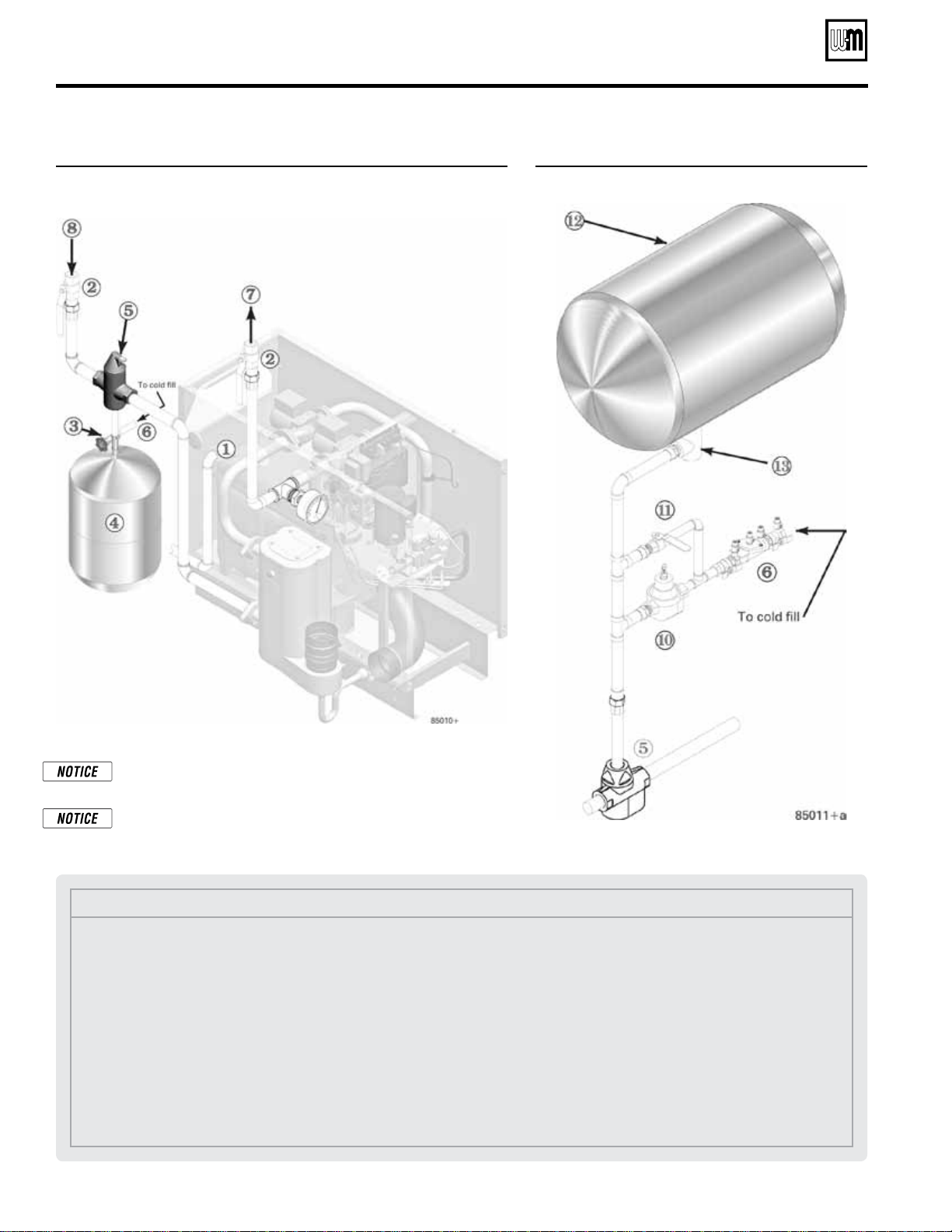
Figure 14 Piping to single-zone system using diaphragm- or
bladder-type expansion tank. Boiler connections are
1” NPT (supply from 1” tee, return to 1” recuperator
flange).
Figure 15 Piping closed-type expansion tank
Pipe diaphragm- or bladder-type expansion tanks to the bot-
tom of the separator.
Pipe closed-type (air in contact with water) tanks to the top of
the air separator. Always connect the fill line to the expansion
tank location, as shown above and in the suggested piping.
Install water piping (continued)
Legend
1 Relief valve discharge piping — see page 12
2 Isolation valves
3 Fill valve
4 Diaphragm-type expansion tank — always locate as
shown in the suggested piping drawings in this manual
5 Air separator
• provide with automatic air vent ONLY when used
with diaphragm-type expansion tanks
• pipe air outlet to expansion tank when used with
close-type tanks
6 Cold fill line, with backflow preventer or check valve
when required by codes (see Figure 15 for typical com-
ponents)
7 System supply piping
8 System return piping
10 Pressure reducing valve, when used
11 Quick-fill bypass valve, when used
12 Closed-type expansion tank — always locate as shown
in the suggested piping drawings in this manual
13 Tank fitting
Part number 550-142-054/1211
15
GV90+ gas-fired water boiler — Boiler Manual
Install water piping (continued)
System water piping methods
Most piping methods shown in this manual use
primary/secondary connection to the boiler loop.
These designs ensure proper flow through the
GV90+ boiler, for the most efficient and reliable
operation of the boiler and the heating system.
For other piping methods, consult your local Weil-
McLain representative.
Circulators
Do not remove either of the GV90+ internal pumps
for use elsewhere in the system. Both pumps are
required for proper operation. Removing a pump
will cause the boiler to malfunction. Substantial
property damage could result.
Never install another pump in series with the
GV90+ boiler
. Forced flow can cause improper op-
eration of the boiler controls. Substantial property
damage could result.
Failure to comply could result in unreliable perfor-
mance and nuisance shutdowns from insufficient
flow.
Circulator ow rate
Size system circulators based on the flow rate required to achieve
the temperature change needed. You can closely estimate tem-
perature rise (or drop) through a circuit by using the following
formula, where TD is temperature rise (or drop), FLOW is flow
rate (in gpm), and BTUH is the heat load for the circuit:
FLOW =
BTUH
—–—–—–—–
TD x 500
Examples:
Consider a system loop for a system with total heating load equal
to 210,000 Btuh. The desired temperature drop through the system
piping is 20°F. Then the required flow rate is:
FLOW =
210,000
—–—–—–—–
20 x 500
= 21 gpm
SIMPLIFIED: For 20° temperature drop, FLOW = MBH / 10.
Circulator head requirement
The circulator must be capable of delivering the required flow
against the head loss that will occur in the piping. Determine
the pipe size needed and the resultant head loss using accepted
engineering methods. The simplified pipe sizing here is limited
to residential systems, and does not include systems with fan coil
units or radiant tubing.
The following simplified method for pipe and cir-
culator sizing must be limited to residential applica-
tions using baseboard (finned or cast iron), cast iron
radiators or convectors. DO NOT apply for radiant
heating, fan coil units or commercial installations.
Simplified pipe/circulator selection
1. Install the boiler and piping using the recommended piping
layouts in this manual.
2. Size the piping and components for each circuit in the space
heating system using Figure 16.
At the ow rates listed, the
head loss in all piping will be 0.04 feet per foot of pipe.
a. Determine the heating load (Btuh) for each circuit.
b. Calculate the flow rate for each circuit using its load.
To use a 20°F temperature drop, just divide the
MBH (1,000’s of Btuh) by 10.
Example — Flow for 20°F temp drop with 35,000
Btuh:
FLOW = 35 MBH / 10 = 3.5 gpm
c. Find the pipe size in Figure 16 that has a max flow rate
just larger than that required for the circuit.
d. Find the total equivalent length (TEL) of the circuit.
TEL accounts for losses through fittings and valves by
using the equivalent length of pipe that would cause
the same head loss. Add these numbers to the measured
length of the circuit to find TEL in feet.
TEL is usually close to 1.5 times the length of the
circuit for residential baseboard, radiator or conv ec-
tor applications.
e. Measure the length of each circuit from the circulator
outlet back to its inlet. Then multiply this length times
1.5 to get the approximate TEL of the circuit.
f. Find the head loss for each circuit:
TEL = 1.5 X Circuit Length (feet)
HEAD = TEL X 0.04 (feet water column)
g. NOTE: Size system header piping for the total flow of
all connected zones.
3. Example:
a. For a circuit with heating load = 45,000 Btuh (= 45
MBH). Measured length of circuit is 88 feet.
b. Flow = 45 MBH / 10 = 4.5 gpm.
c. TEL = 1.5 x 88 feet = 132 feet.
d. From Figure 16, select 1" pipe (max flow = 8 gpm).
e. Head loss = TEL x 0.04 = 132 x 0.04 = 5.28 feet.
f. Select a circulator that can deliver at least 4.5 gpm at a
head of 5.28 feet. (Read the NOTICE below.)
To use this method, limit the flow through ¾"
finned-tube baseboard to 3.9 gpm, or use 1" base-
board and limit flow to 7.1 gpm. If the total load
of the circuit requires more flow, split the circuit
into two or more.
Figure 16
Flow rates for 0.04 feet head loss per foot of
copper pipe
(based on water at140°F)
Pipe size
(inches)
MAX Flow rate (GPM)
@ 0.04 feet per foot
Pipe size
(inches)
MAX Flow rate (GPM)
@ 0.04 feet per foot
¾
4
2
45
1
8
2½
75
1¼
14
3
140
1½
22
4
290
Part number 550-142-054/1211
GV90+ gas-fired water boiler — Boiler Manual
16
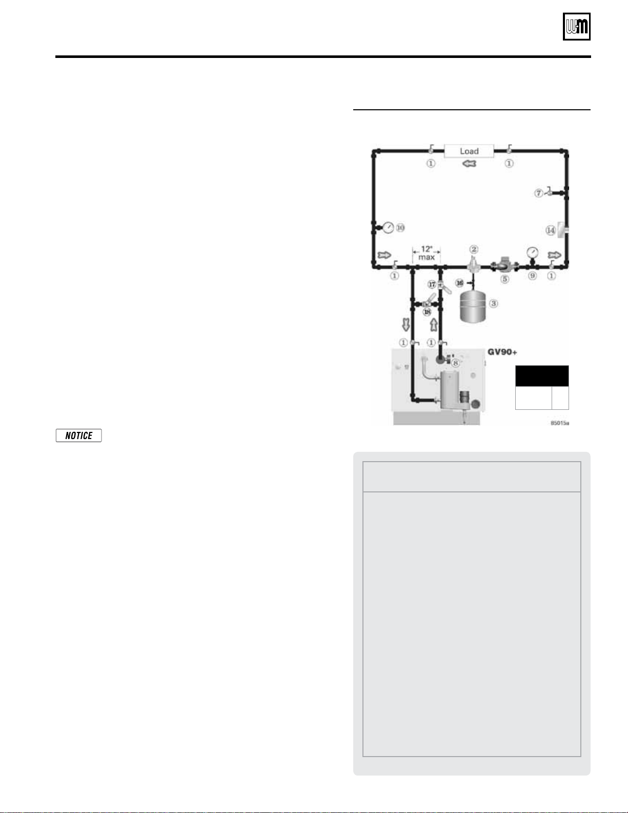
Figure 17 Baseboard system — circulator zoning
Baseboard system piping —
CIRCULATOR zoning (primary/secondary)
Apply Figure 17 for circulator zoning on systems using baseboard
heaters. The heaters can be any baseboard style, including finned tube
or cast iron.
Zoning with circulators — The GV90+ internal system
circulator cannot be removed from the boiler for use as
one of the zone circulators. It must remain as shipped
from the factory to allow proper flow control inside the
boiler. You will need a circulator for each zone. Provide
circulator relays or circulator zone controller.
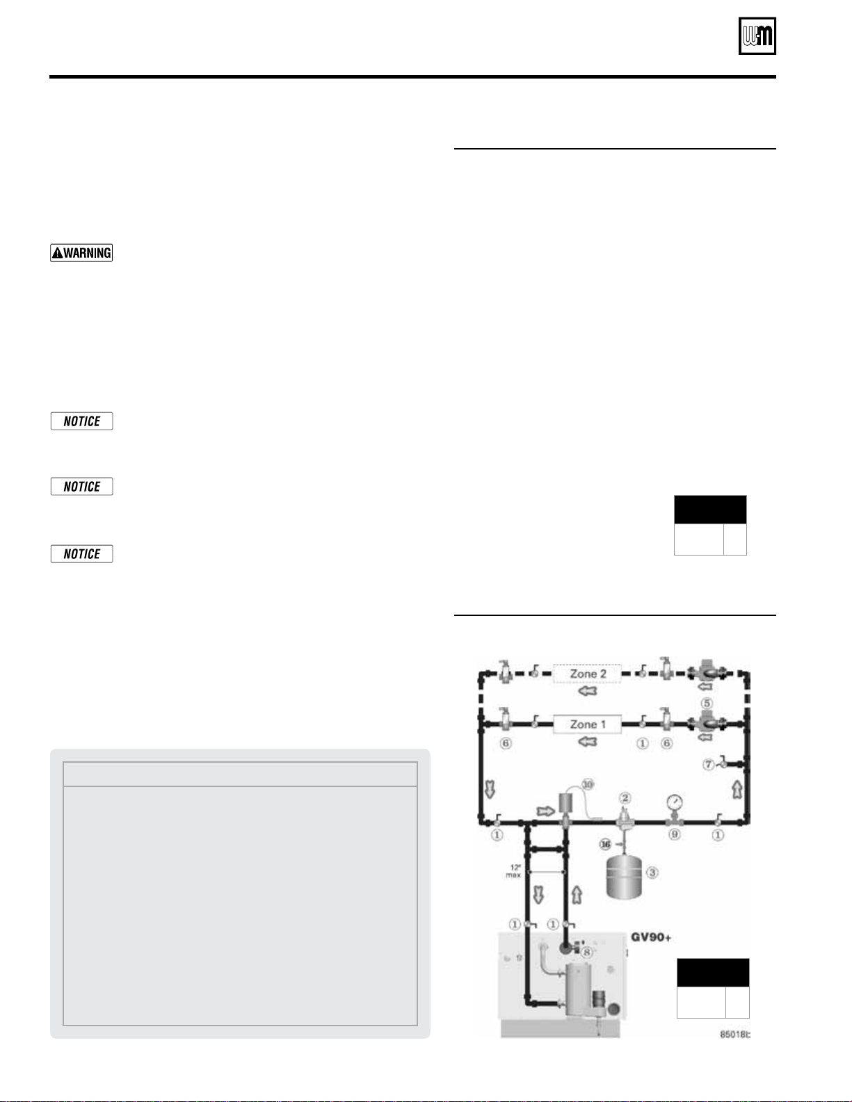
Baseboard system piping —
ZONE VALVE zoning (direct connection)
The boiler internal circulator can be used to circulate many zone-valve
zoned systems as shown in Figure 18, page 17 for application on systems
using baseboard (finned tube or cast iron).
• DO NOT apply this piping when using a GV90+6 — the internal
circulator cannot supply enough ow to the system
.
• When applying Figure 18, page 17, DO NOT exceed the limits
shown in Figure 19, page 17
.
• For systems requiring higher ow or head loss, apply the
suggested piping of Figure 20, page 18, NOT that of Fig-
ure 18, page 17.
Balancing, when required
—
Substitute a memory-stop
valve for one of the isolation valves in each zone to use
the memory-stop valve for balancing flow as well as
isolation.
Zoning with zone valves —
Provide a separate 24-volt
transformer to power the zone valves. Size the trans-
former to handle the total rated load of all connected zone
valves. Alternatively, use a zone valve zone controller.
Applying Figure 18, page 17
1. Figure 18, page 17 and Figure 19, page 17 provide guidelines for
checking whether the GV90+ internal circulator can provide suffi-
cient flow when directly connected to a two-pipe baseboard system.
The outputs of GV90+ boilers are all too high for con-
nection to a single-loop series-loop system. To apply to
an existing series loop system, the system must be fitted
with trunk lines to convert to a split-loop system. Pro-
vide either one or two trunk lines to meet the minimum
number of circuites and maximum loading per circuit
given in Figure 19, page 17.
2. The system pipe sizing must be no smaller than shown in the
Legend for Figure 18, page 17.
3. Values shown for maximum circuit lengths, maximum load per
circuit and the maximum feet baseboard per circuit are limits that
ensure the internal circulator will have sufficient head to provide
the flow needed for each circuit.
MINIMUM
Boiler loop pipe size
GV90+3/4
GV90+5/6
1”
1¼”
Legend
1 Isolation valves
2 Automatic air vent (with
diaphragm-type expan-
sion tank), or connect to
tank fitting (closed-type
expansion tank).
3 Diaphragm- or bladder-
type expansion tank, if
used. (For closed-type
expansion tank, pipe
from top of air separa-
tor to tank fitting as in
Figure 15, page 14.)
5 Zone circulator
6 Flow/check valve
7 Hose bibb purge valve
8 Boiler pressure/tempera-
ture gauge
16 Cold water fill line — see
Figure 15, page 14 for
typical components
Install water piping (continued)
Part number 550-142-054/1211
17
GV90+ gas-fired water boiler — Boiler Manual
Legend
1 Isolation valves
2 Automatic air vent (with
diaphragm-type expan-
sion tank), or connect to
tank fitting (closed-type
expansion tank).
3 Diaphragm- or bladder-
type expansion tank, if
used. (For closed-type
expansion tank, pipe from
top of air separator to
tank fitting as in Fig-
ure 15, page 14.)
4 Zone valve
7 Hose bibb purge valve
8 Boiler pressure/tempera-
ture gauge
10 Differential pressure by-
pass valve
16 Cold water fill line — see
Figure 15, page 14 for
typical components
Pipe sizes (NPT), minimum
Boiler model
Mains
Circuits
GV90+3
GV90+4
1" ¾"
GV90+5 1¼" ¾"
Circuit requirements
See Figure 19
Install water piping (continued)
Figure 18 Zone valve zoning — GV90+3, GV90+4 or GV90+5
(DO NOT apply to GV90+6)
Figure 19 The system must meet the following requirements when applying Figure 18
Boiler
model
Circulator HEAD
available to the
system
Maximum
circuit
length
L
Minimum
number
of circuits
Max load
of any
circuit
Max feet baseboard
of any circuit
(@ 600 Btuh/foot)
Summary
GV90+3
6.4 feet w.c.
@ 6.5 GPM
103 feet 2 40 MBH 67 feet
6.5 GPM total
(max 4GPM any cricuit)
20°F temperature drop
GV90+4
4.1 feet w.c.
@ 9.7 GPM
92 feet 3 33 MBH 55 feet
9.7 GPM total
(max 3.3 GPM any circuit)
20°F temperature drop
GV90+5
*
5.5 feet w.c.
@8.7 GPM
112 feet 3 53 MBH 88 feet
8.7 GPM
(max 3.5 GPM any circuit)
30°F temperature drop
GV90+6 DO NOT apply to GV90+6 — Use primary/secondary piping ONLY, as in Figure 20, page 18.
* This application may be marginal. It could cause temperature distribution problems, because the temperature drop is 30°F,
NOT 20°F. The best method is to use primary/secondary piping for the GV90+5 as in Figure 20, page 18.
One-pipe diverter tees systems
— The ap-
plication information on this page is based
on two-pipe baseboard systems.
To check
whether the internal circulator can provide
sufficient flow to a one-pipe diverter tee
system, use the available head value given in
Figure 19, page 17.

Part number 550-142-054/1211
GV90+ gas-fired water boiler — Boiler Manual
18
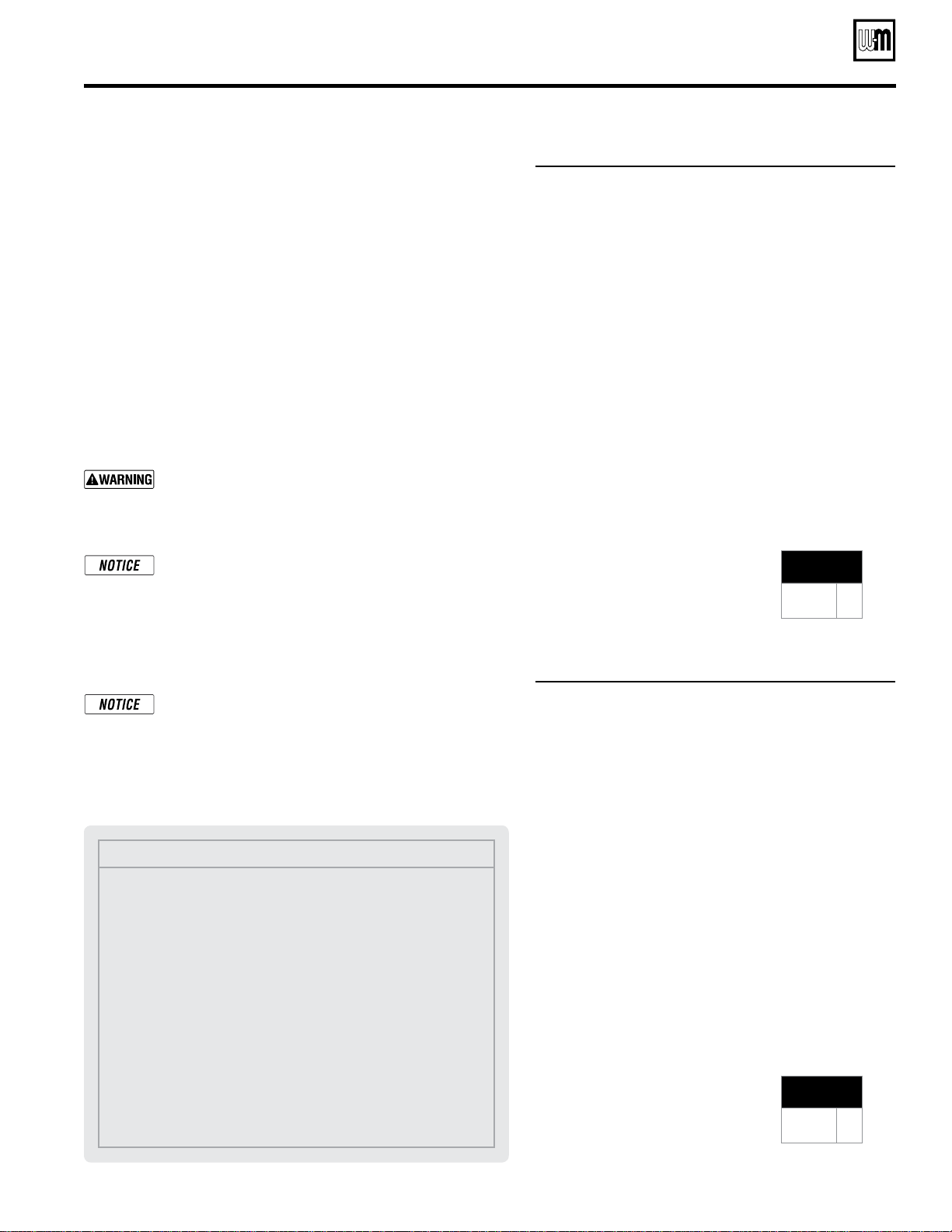
Figure 20 Radiator system — zone-valve zoning
Figure 21 Radiator system — circulator zoning
Radiator system piping
Apply Figure 20 (zone-valve zoning) or Figure 21 (circulator zoning)
to systems using standing cast iron radiators. This applies to gravity
water systems and converted steam systems using columnar, tubular
or recessed cast iron radiators.
The suggested piping for zone-valve zoning radiator systems differs
from baseboard systems because of the high water content of cast iron
radiators. The GV90+ internal circulators automatically regulate supply
and internal bypass flow based on the temperature of the water return-
ing to the boiler. At the start of many heating cycles in a radiator system,
the water in the radiators is cool. So the boiler would slow down system
flow rate while sending out relatively hot water. This could cause heat
distribution problems. Install a separate system circulator as shown
in Figure 20 when zoning with zone valves. The separate circulator
assures a relatively constant temperature drop through the system.
The boiler internal circulators must be left in the boiler. They cannot
be removed for use a zoning circulator. Provide a circulator for each
zone when circulator zoning, and pipe the system as in Figure 21.
Balancing, when required
—
Substitute a memory-stop
valve for one of the isolation valves in each zone to use
the memory-stop valve for balancing flow as well as
isolation.
Zoning with zone valves —
Provide a separate 24-volt
transformer to power the zone valves. Size the trans-
former to handle the total rated load of all connected zone
valves. Alternatively, use a zone valve zone controller.
Zoning with circulators — The GV90+ internal system
circulator cannot be removed from the boiler for use as
one of the zone circulators. It must remain as shipped
from the factory to allow proper flow control inside the
boiler. You will need a circulator for each zone. Provide
circulator relays or circulator zone controller.
The system circulator must be supplied by the in-
staller.
MINIMUM
Boiler loop pipe size
GV90+3/4
GV90+5/6
1”
1¼”
MINIMUM
Boiler loop pipe size
GV90+3/4
GV90+5/6
1”
1¼”
Legend
1 Isolation valves
2 Automatic air vent (with diaphragm-type expansion tank), or
connect to tank fitting (closed-type expansion tank).
3 Diaphragm- or bladder-type expansion tank, if used. (For closed-
type expansion tank, pipe from top of air separator to tank fitting
as in Figure 15, page 14.)
4 Zone valve
5 System or zone circulator
6 Flow/check valve
7 Hose bibb purge valve
8 Boiler pressure/temperature gauge
9 System supply temperature gauge
10 Differential pressure by-pass valve
16 Cold water fill line — see Figure 15, page 14 for typical components
Install water piping (continued)
(0ptional)
Part number 550-142-054/1211
19
GV90+ gas-fired water boiler — Boiler Manual
Figure 22 Single-zone radiant heating or
heat pump system
Single-zone radiant heating or heat pump
Radiant heating systems and heat pump systems usually require
system supply water temperatures below 140°F. But the boiler outlet
water temperature will be at least 150°F to 160°F during most operat-
ing conditions. So the piping must include a method of reducing the
supply water temperature to the system.
Figure 22 uses two balancing valves to manually adjust the supply water
temperature. Follow the instructions below to adjust these valves. Install
the supply temperature limit control (item 14) as shown to protect the
system from over-temperature conditions. Note also that this piping
requires a separate system circulator, as shown, because of the higher
flow rates of radiant and heat pump systems.
Manual adjustment of the supply temperature is limited to single-
zone systems because multi-zone systems will cause varying loads,
making it unlikely an acceptable valve setting could be found. See
Figure 23, page 20 or Figure 24, page 20 for multi-zone systems.
You may also apply the suggested piping of either Figure 23, page 20 or
Figure 24, page 20 if you want automatic supply temperature regulation
or outdoor reset temperature control.
For additional information and alternatives in piping for radiant heat-
ing systems, contact Weil-McLain.
The system circulator must be supplied by the in-
staller.
Adjust balancing valves
Use valves 17 and 18 to mix boiler supply water with system return
water, reducing supply water temperature to the system.
1. Subtract the design system supply temperature from 150°F. Call
this number the
temperature difference.
2. Open valve 17 and close valve 18.
3. Start the boiler and system.
4. Let the system warm up for about 15 minutes.
5. Note the temperature at gauge 9 (system supply) and gauge 8
(boiler supply).
6. Slowly close valve 17 while opening valve 18 until gauge 9 reads
lower than gauge 8 by at least the temperature difference found
in step 1.
7. Example: For a design supply temperature of 100°F, the
tempera-
ture difference
would be 150°F minus 100°F, or 50°F. Set the valves
until gauge 9 reads at least 50°F lower than gauge 8.
MINIMUM
Boiler loop pipe size
GV90+3/4
GV90+5/6
1”
1¼”
Legend
1 Isolation valves
2 Automatic air vent (with diaphragm-type expansion
tank), or connect to tank fitting (closed-type expan-
sion tank).
3 Diaphragm- or bladder-type expansion tank, if used
(For closed-type expansion tank, pipe from top of air
separator to tank fitting as in Figure 15, page 14.)
5 System circulator
7 Hose bibb purge valve
8 Boiler pressure/temperature gauge
9 System supply temperature gauge
10 Return temperature gauge
14 Supply temperature limit control — Set at a tempera-
ture below the maximum allowed for the system or as
directed by the system designer.
16 Cold water fill line — see Figure 15, page 14 for typical
components
17 Balancing valve
18 Balancing valve
Install water piping (continued)
Part number 550-142-054/1211
GV90+ gas-fired water boiler — Boiler Manual
20
Figure 23 Auto system supply temp regulation —
zone valve zoning
Figure 24 Auto system supply temp regulation —
circulator zoning
Multi-zone radiant heating system
Multi-zone systems require automatic regulation of the system sup-
ply temperature because of widely varying load conditions. Figure 23
(zone-valve zoning) and Figure 24 (circulator zoning) show suggested
piping for these systems.
Provide an automatic temperature control valve or
motor-operated valve which can be adjusted for the
desired supply water temperature. This is required to
protect the radiant system from excessive temperature.
Zone-valve zoning — The suggested piping uses a separate circulator
for system circulation to provide the higher flow typical of radiant
heating systems and to assure good temperature distribution in the
system when the return water temperature is low.
Circulator zoning — The GV90+ internal circulators must not be
removed. Provide a separate circulator for each zone.
Balancing, when required
—
Substitute a memory-stop
valve for one of the isolation valves in each zone to use
the memory-stop valve for balancing flow as well as
isolation.
Zoning with zone valves —
Provide a separate 24-volt
transformer to power the zone valves. Size the trans-
former to handle the total rated load of all connected zone
valves. Alternatively, use a zone valve zone controller.
Zoning with circulators — The GV90+ internal system
circulator cannot be removed from the boiler for use as
one of the zone circulators. It must remain as shipped
from the factory to allow proper flow control inside the
boiler. You will need a circulator for each zone. Provide
circulator relays or circulator zone controller. The sys-
tem circulator must be supplied by the installer.
Outdoor reset
Apply Figure 23 or Figure 24 for any system intended for outdoor reset
of the supply water temperature. Use a motor-operated three-way valve
and an outdoor reset temperature control system.
MINIMUM
Boiler loop pipe size
GV90+3/4
GV90+5/6
1”
1¼”
MINIMUM
Boiler loop pipe size
GV90+3/4
GV90+5/6
1”
1¼”
Legend
1 Isolation valves
2 Automatic air vent (with diaphragm-type expansion tank), or
connect to tank fitting (closed-type expansion tank).
3 Diaphragm- or bladder-type expansion tank, if used (For closed-
type expansion tank, pipe from top of air separator to tank fitting
as in Figure 15, page 14.)
4 Zone valve
5 System or zone circulator
6 Flow/check valve
7 Hose bibb purge valve
8 Boiler pressure/temperature gauge
9 System supply temperature gauge
10 Supply temperature automatic mixing valve
11 Differential pressure by-pass valve
16 Cold water fill line — see Figure 15, page 14 for typical components
Install water piping (continued)
Part number 550-142-054/1211
21
GV90+ gas-fired water boiler — Boiler Manual
Figure 25 Auto return temp regulation — circulator
zoning
Piping snow melt systems or combination
snow melt/space heating systems
Combination snow melt/space heating systems can have return water
temperature below 60°F, and the return temperature will fluctuate. So
these systems require automatic return water temperature as shown in
Figure 25 (zone-valve zoning) or Figure 26 (circulator zoning).
Select an automatic temperature control valve or motor-operated valve
which can be adjusted to provide a return water temperature of at least
60°F. Any setting higher than 60°F will also be acceptable.
Zone-valve zoning — The suggested piping uses a separate circulator
for system circulation to assure good temperature distribution in the
system when the return water temperature is low.
Circulator zoning — The GV90+ internal circulators must not be
removed. Provide a separate circulator for each zone.
The return water temperature to the boiler must be
at least 60°F. Provide and apply means to regulate the
return temperature. Failure to do so can result in boiler
control operation problems, causing possible significant
property damage.
Zoning with zone valves
— Each zone in the piping
diagrams in this section is shown with an isolation valve
on each side. Substitute a memory-stop valve for one of
these in each zone in order to use the memory-stop valve
for balancing flow as well as isolation.
Pr
ovide a separate 24-volt transformer to power the zone
valves. Size the transformer to handle the total rated load
of all connected zone valves.
Zoning with circulators — The GV90+ internal system
circulator cannot be removed from the boiler for use as
one of the zone circulators. It must remain as shipped
from the factory to allow proper flow control inside the
boiler. You will need a circulator for each zone. Provide
circulator relays or circulator zone controller.
The sys-
tem circulator must be supplied by the installer.
MINIMUM
Boiler loop pipe size
GV90+3/4
GV90+5/6
1”
1¼”
MINIMUM
Boiler loop pipe size
GV90+3/4
GV90+5/6
1”
1¼”
Legend
1 Isolation valves
2 Automatic air vent (with diaphragm-type expansion tank), or
connect to tank fitting (closed-type expansion tank).
3 Diaphragm- or bladder-type expansion tank, if used (For closed-
type expansion tank, pipe from top of air separator to tank fitting
as in Figure 15, page 14.)
4 Zone valve
5 System or zone circulator
6 Flow/check valve
7 Hose bibb purge valve
8 Boiler pressure/temperature gauge
9 System supply temperature gauge
10 Return temperature automatic mixing valve
11 Differential pressure by-pass valve
16 Cold water fill line — see Figure 15, page 14 for typical components
Figure 26 Auto return temp regulation — zone valve
zoning
Install water piping (continued)
Part number 550-142-054/1211
GV90+ gas-fired water boiler — Boiler Manual
22
Figure 27 Installing GV90+ boiler in system with
water chiller
Water chiller systems
Pipe the boiler and water chiller as shown in Figure 27.
Install boiler, as shown, so chilled medium is piped in parallel with
heating boiler.
Use appropriate valves to prevent chilled medium from entering boiler.
See Figure 27 for typical installation of balancing valve and check valve.
Install the flow/check valve in the boiler supply piping, as shown in
Figure 27, to prevent gravity circulation during the cooling cycle.
If boiler is connected to heating coils located in air handling units where
they can be exposed to refrigerated air, use flow control valves or other
automatic means to prevent gravity circulation during cooling cycle.
Balancing, when required
—
Substitute a memory-stop
valve for one of the isolation valves in each zone to use
the memory-stop valve for balancing flow as well as
isolation.
Zoning with zone valves —
Provide a separate 24-volt
transformer to power the zone valves. Size the trans-
former to handle the total rated load of all connected zone
valves. Alternatively, use a zone valve zone controller.
Zoning with circulators — The GV90+ internal system
circulator cannot be removed from the boiler for use as
one of the zone circulators. It must remain as shipped
from the factory to allow proper flow control inside the
boiler. You will need a circulator for each zone. Provide
circulator relays or circulator zone controller.
Chilled water systems often use closed-type expansion
tanks, as shown in Figure 27. DO NOT install automatic
air vents on these systems.
MINIMUM
Boiler loop pipe size
GV90+3/4
GV90+5/6
1”
1¼”
Install water piping (continued)
Legend
1 Isolation valves
2 Air separator
3 Expansion tank with tank fitting (piping shown for
application of a closed-type expansion tank)
5 System circulator
6 Flow/check valve
8 Boiler pressure/temperature gauge
16 Cold water fill line — see Figure 15, page 14 for typical
components
17 Balancing valve
19 Chiller
20 Strainer
21 Check valve
22 System supply
23 System return
Part number 550-142-054/1211
23
GV90+ gas-fired water boiler — Boiler Manual
Multiple boiler installations
Placing multiple boilers
1. Locate multiple boilers in boiler room according
to:
a. Figure 28 (side-to-side), or
b. Figure 29 (back-to-back).
2. Provide the clearances indicated in the illustrations
listed above to provide for access and servicing. If
these recommended dimensions are not possible,
provide at least the recommended service clearances
given on page 6. Also follow local codes.
3. Construct boiler foundation if boiler room floor
is uneven or if there is a danger of flooding. Size
foundation to allow for clearance and spacing di-
mensions shown in the illustrations at right.
4. Chalkline boiler locations on foundation or boiler
room floor.
5. Uncrate, assemble and mount boilers according to
instructions in this manual.
6. Provide clearance for installation of venting, air
piping, gas piping, expansion tank, primary circula-
tor and other accessories.
Controlling multiple GV90+
boilers
1. Multiple GV90+ boilers can be controlled using any
boiler control/sequencing system that provides an
isolated contact for call for heat (connected to the
boiler's T-T terminals).
Piping multiple GV90+ boilers
1. See suggested piping diagrams in this manual.
Contact Weil-McLain for assistance for systems
not covered.
2. Always pipe the boilers on a secondary loop in a
primary/secondary circuit as shown in the examples
in this manual.
Figure 28 Side-to-side mounting of multiple GV90+ boilers,
showing RECOMMENDED clearances
Figure 29 Back-to-back installation of multiple GV90+ boilers,
showing RECOMMENDED clearances

Part number 550-142-054/1211
GV90+ gas-fired water boiler — Boiler Manual
24
Multiple boiler water piping
Easy-Fit® piping installation
1. Main header and Easy-Fit
®
Manifold pipe sizing.
a. New system — See page 15.
b. Replacing boilers in an existing system — Without reducing
size, connect system supply and return lines. Install tees or
crosses for Easy-Fit
®
manifolds as shown in Figure 30 or Fig-
ure 31. Size manifolds to handle total connected boiler output
as shown.
2. Provide connections in main header for Easy-Fit® manifolds as
close as possible to the midpoint of multiple boilers.
a. Use tees for four or less boilers, as in Figure 30.
b. Use either tees (Figure 30) or crosses (Figure 31) for five or
more boilers.
3. Manifold placement:
a. To alternate spacing for supply and return lines to boilers,
reverse the short-end and long-end of the manifolds as shown
in Figure 30 and Figure 31.
b. Return manifold must be on the return side of the main and
supply manifold must be on the supply side of the main. Draw-
ings in this manual show flow in system main from right to
left. For system flowing left to right, reverse the locations of
the manifolds accordingly.
4. Connect from Easy-Fit® manifold branches to boiler supply and
return connections using copper or steel pipe, sized for the required
flow rate.
5. Provide a flow/check valve in the supply piping of each boiler as
shown in piping diagrams in this manual. Install an isolation valve
on the supply and return of each boiler as shown. Some local codes
may require the use of individual water level controls and limits
on each boiler when isolation valves are installed.
6. Install main system air eliminator and primary circulator in sup-
ply piping as shown in piping diagrams. Place expansion tank on
suction side of system circulator as shown.
7. Install system accessories as shown in drawings.
8. Piping recommendation drawings:
a. Figure 30 and Figure 31 show details of Easy-Fit
®
manifolds.
b. Figure 32, page 25 is a schematic piping drawing showing the
locations of typical boiler piping and system piping, including
limits and other devices often required by local codes.
c. Figure 33, page 26 and Figure 34, page 27 are three-dimensional
piping drawings of typical multiple boiler installation.
d. Figure 35, page 28 shows recommended piping when an isolat-
ing heat exchanger is needed.
9. If desired, other primary/secondary piping arrangements can be
used.
When using isolation valves on each boiler, some codes
may require providing a low water control and additional
limit for each boiler. Consult local codes to determine
if omission of the individual boiler isolation valves may
allow the use of a single water level control and additional
limit for the entire multiple boiler system.
Maximum connected load per manifold:
2-inch manifold — 450 MBH
3-inch manifold — 1400 MBH
4-inch manifold — 2900 MBH
Figure 30
Single-sided EZ-Fit Header connection
Figure 31 Double-sided EZ-Fit Header connection

Part number 550-142-054/1211
25
GV90+ gas-fired water boiler — Boiler Manual
Multiple boiler water piping (continued)
Legend — Figure 32
1 Flow/check valve (each boiler)
2 Isolation valves (when used)
3 Cap
4 Easy-Fit® Manifold (supply) — layout and size per
page 24
5 Easy-Fit® Manifold (return) — layout and size per
page 24
6 Primary circulator
7 Expansion tank (diaphragm type)
8 System air eliminator
9 System automatic air vent
10 Pressure reducing valve
11 Check valve or backflow preventer, as required by applicable
codes
12 Isolation valve
13 Water flow switch (when used)
14 Supply water temperature control (when used)
15 Low water cutoff (when used) (place above primary header)
16 Cold water fill line — see Figure 15, page 14 for typical
components
18 System supply
19 System return
20 (Not shown) Boiler relief valve and discharge piping, installed
per GV90+ Boiler Manual
30 Long end of manifold
Figure 32 Piping schematic — typical for multiple GV90+ boilers, using Weil-McLain Easy-Fit manifolds

Part number 550-142-054/1211
GV90+ gas-fired water boiler — Boiler Manual
26
Multiple boiler water piping (continued)
Legend — Figure 33
1 Flow/check valve (each boiler)
2 Isolation valves (when used)
3 Caps
4 Easy-Fit® Manifold (supply) — layout and size per page 24
5 Easy-Fit® Manifold (return) — layout and size per page 24
6 Primary circulator
7 Expansion tank (diaphragm type)
8 System air eliminator
9 System automatic air vent
16 Cold water fill line — see Figure 32, page 25 for typical com-
ponents
17 3-way diverting valve (operated by DHW aquastat — valve end
switch connects across boiler thermostat terminals)
18 System supply
19 System return
20 Boiler relief valve and discharge piping, installed per GV90+
Boiler Manual
21 Indirect-fired storage water heaters — Example is shown connect-
ed to one boiler of the system. The indirect water heater could
also be connected with a secondary connection off the main
header, as in Figure 34, page 27.
Figure 33 Piping layout — typical for multiple GV90+ boilers, using Weil-McLain Easy-Fit manifolds (2-boiler system)

Part number 550-142-054/1211
27
GV90+ gas-fired water boiler — Boiler Manual
Figure 34 Piping layout — typical for multiple GV90+ boilers, with DHW storage heaters (4-boiler system)
Suggested DHW
boiler-side pipe
sizing
(for max 0.04
feet head loss per foot of
total equivalent length,
TEL)
Flow rate Size Flow rate Size
1 – 4 gpm ¾” 22 – 45 gpm 2”
4 – 8 gpm 1” 45 – 75 gpm 2½”
8 – 14 gpm 1¼” 75 - 140 gpm 3”
14 – 22 gpm 1½” 140 – 290 gpm 4”
Legend — Figure 34
1 Flow/check valve (each boiler)
2 Isolation valves (when used)
3 Caps
4 Easy-Fit® Manifold (supply) — layout and
size per page 24
5 Easy-Fit® Manifold (return) — layout and size
per page 24
6 Primary circulator
7 Expansion tank (diaphragm type)
8 System air eliminator
9 System automatic air vent
16 Cold water fill line — see Figure 32, page 25
for typical components
18 System supply
19 System return
20 Boiler relief valve and discharge piping,
installed per GV90+ Boiler Manual
21 Indirect-fired storage water heaters — Example is shown with a boiler
water circulator on each water heater. Alternatively, the water heaters could
be connected with reverse return piping, using a common circulator.
22 Boiler water inlet
23 Boiler water outlet
24 DHW boiler-side circulators
25 DHW boiler-side return Easy-Fit® Manifold
26 DHW boiler-side supply Easy-Fit® Manifold
27 Flow/check valves (to prevent induced or gravity flow in heating system or
DHW piping)
28 Check valve to prevent heat migration in heating system
29 Drain valves
30 Sensor for BCP (boiler control panel), when used
Note: See water heater manual for DHW piping — The DHW piping must also
be manifolded together since the boiler-side piping is manifolded. If DHW
heaters supply separate DHW circuits, provide an individual circulator for
each water heater, and control each circulator by its water heater’s aquastat.
This piping is sug-
ges t e d only. The
layout above should be controlled
with a boiler sequencing panel that
provides DHW operation as well.
Wire the heating system circulator
to operate only on call for heat. Al-
ternatively, use the boiler sequencing
panel to provide domestic priority
by disabling the heating system cir-
culator any time there is a DHW call
for heat. The boiler internal circula-
tors operate on any call for heat,
whether heating system or DHW.
Offset the DHW boiler-side supply
and return manifolds as shown so
the total run of pipe and fittings to
each of the water heaters is approxi-
mately equal.
Multiple boiler water piping (continued)
Part number 550-142-054/1211
GV90+ gas-fired water boiler — Boiler Manual
28
Multiple boiler water piping (continued)
Figure 35 Piping layout — typical for multiple GV90+ boilers, using isolation exchanger
Legend — Figure 35
1 Flow/check valve (each boiler)
2 Isolation valves (when used)
3 Cap
4 Easy-Fit® Manifold (supply) —
layout and size per page 24
5 Easy-Fit® Manifold (return) — lay-
out and size per page 24
6a Heating system circulator (exchang-
er tube-side)
6b Heat exchanger shell-side circulator
7 Expansion tanks (diaphragm type)
8 System air eliminator
9 System automatic air vent
13 Cold water supply connections
16 Cold water fill line — see Fig-
ure 32, page 25 for typical compo-
nents
18 Heating system supply
19 Heating system return
20 Boiler relief valve and discharge
piping, installed per GV90+ Boiler
Manual
30 Sensor for BCP (boiler control
panel), when used
Notes:
1. Contact heat exchanger manufacturer for heat ex-
changer shell-side and tube-side piping and circulator
requirements. Tube-side flow and temperatures must
meet heating system requirements.
2. Contact heat exchanger manufacturer for sizing heat
exchanger.
3. Heat exchanger shell-side circuit requires its own
expansion tank as shown.
4. Heating system circuit requires its own expansion tank,
as shown, plus its own relief valve set to protect heating
system and heat exchanger piping and components.
5. When individual isolation valves are used, individual
boiler and level controls may be required.
Use isolation heat
exchanger for:
1. Large volume systems with high
mineral content in water.
2. Systems exposed to untreated
quantities of makeup water.
3. Old systems severely contami-
nated with scale and rust buildup
inside piping and heat distribu-
tion units.
4. Process applications.
5. Commercial service water ap-
plications.
6. High water pressure applications,
requiring pressure relief setting
in heating system more than 50
PSIG (tall buildings). See notes
below.
Part number 550-142-054/1211
29
GV90+ gas-fired water boiler — Boiler Manual
Venting & air — general
GV90+ boilers must be vented and
supplied with combustion and venti-
lation air using piping and methods
described in this manual
.
Every boiler must have its own vent.
DO NOT common vent with any other
appliance.
Inspect finished vent and air piping
thoroughly to ensure all are airtight
and comply with the instructions
provided and with all requirements of
applicable codes.
Failure to provide a properly-installed
vent and air system will cause severe
personal injury or death.
If the vent/air piping configurations
covered in the GV90+ boiler manual
cannot be applied for a particular
installation, contact Weil-McLain for
assistance. Other configurations may
be available.
Where vent piping is routed through
an unheated space
, apply minimum
1 inch of foil-faced fiberglass insulation
on the length of the vent pipe in the
unheated space.
Installations must comply with local
requirements and with the National
Fuel Gas Code, ANSI Z223.1 for U.S.
installations or CSA B149.1 or B149.2
for Canadian installations.
Use only the materials listed in this
manual for vent and air pipe and fit-
tings. See Figure 40, page 33.
If used, a masonry chimney can
ONLY be used as a PIPE CHASE for
vent and air pipes
— The vent and air
piping must be installed as instructed
in this manual and all joints must be
sealed. The chimney must be used
only for GV90+ boilers. NO OTHER
appliance or fireplace can be connected
to the chimney. The chimney must be
straight, with no offsets, and the vent
and air piping materials must comply
with this instruction manual. The
chimney must be fitted with a sealed
access opening, through which the in-
terior of the chimney can be inspected.
The chimney (and liner, if installed)
must be inspected at least once annu-
ally to verify condition.
Failure to comply could result in severe
personal injury, death or substantial
property damage.
When removing a boiler from an existing
common vent system
The GV90+ boiler cannot be common vented with any other
appliance.
When an existing boiler is replaced with a GV90+ boiler,
the GV90+ boiler CANNOT use the existing common vent. The GV90+
boiler requires its own vent and air piping, as specified in this manual. This
may cause a problem for the appliances that remain on the old common
vent, because the vent may be too large. The following test, required by
ANSI Z21.13, is intended to check for proper operation of the appliances
remaining on the old common vent system.
Vent system verication
At the time of removal of an existing boiler, the following steps shall be
followed with each appliance remaining connected to the common venting
system placed in operation, while the other appliances remaining connected
to the common venting system are not in operation. Seal any unused open-
ings in the common venting system.
Existing vent test procedure
(The following is intended to test whether the appliances
remaining on an existing vent system will operate
satisfactorily.)
1. Visually inspect the venting system for proper size and horizontal pitch
and determine there is no blockage or restriction, leakage, corrosion or
other deficiencies which could cause an unsafe condition.
2. Test vent system — Insofar as is practical, close all building doors and
windows and all doors between the space in which the appliances
remaining connected to the common venting system are located and
other spaces of the building. Turn on clothes dryers and any appliance
not connected to the common venting system. Turn on any exhaust
fans, such as range hoods and bathroom exhausts, so they will oper-
ate at maximum speed. Do not operate a summer exhaust fan. Close
fireplace dampers.
3. Place in operation the appliance being inspected. Follow the lighting in-
structions. Adjust thermostat so appliance will operate continuously.
4. Test for spillage at draft hood relief opening after 5 minutes of main
burner operation. Use the flame of a match or candle, or smoke from
a cigarette, cigar, or pipe.
5. After it has been determined that each appliance remaining connected
to the common venting system properly vents when tested as outlined
herein, return doors, windows, exhaust fans, fireplace dampers, and any
other gas-burning appliance to their previous conditions of use.
Any improper operation of common venting system should be corrected
so the installation conforms with the National Fuel Gas Code, ANSI Z223.1
— latest edition. Correct by re-sizing to approach the minimum size as
determined using the appropriate tables in Part 11 of that code. Canadian
installations must comply with B149.1 or B149.2 Installation Code.
Part number 550-142-054/1211
GV90+ gas-fired water boiler — Boiler Manual
30
Venting & air — general (continued)
Provide combustion air:
DIRECT VENT — The installation must provide com-
bustion air piping. In addition, ventilation openings
may be required.
DIRECT EXHAUST — The installation must provide
combustion air openings to the boiler space.
ALL APPLICATIONS — The installation must provide
combustion air openings as needed for other appli-
ances in the space.
Vent and air termination options
1. Vent and air piping must terminate out the sidewall or through the
roof of the building, using only one of the methods described in this
manual. See Figure 39, page 32 and Figure 40, page 33 for allowable
configurations and piping materials.
DIRECT VENT installations
1. For direct venting, combustion air must be piped from outside to the
boiler, following the instructions in this manual, and compliant with
all applicable codes.
2. Ventilation openings are required for some spaces. See Fig-
ure 42, page 36.
3. If other appliances are located in the same space with the GV90+ boiler,
provide openings shown in Figure 42, page 36.
If combustion and ventilation air openings are not provided
as directed above and the room does not have adequate
ventilation, the higher temperature in the space may result
in reduced component life.
DIRECT EXHAUST installations
1. Combustion and ventilation air must be provided in the boiler room
on direct exhaust installations. Follow all instructions in this manual
(see page 49 for air opening instructions) and all applicable codes to
provide required air openings.
DO NOT sidewall vent DIRECT EXHAUST APPLICATIONS
at altitudes above 5,500 feet. Sidewall venting is only allowed
for DIRECT VENT applications (ducted combustion air) at
altitudes above 5,500 feet.
Combustion air contamination:
Ensure that the combustion air will
not contain any of the contaminants
in Figure 36
.
DO NOT place combustion air supply
openings or intake terminations near
a swimming pool, for example.
Avoid areas subject to exhaust fumes
from laundry facilities. These areas will
always contain contaminants.
Figure 36
Corrosive contaminants and sources
Products to avoid
Spray cans containing chloro/fluorocarbons
Permanent wave solutions
Chlorinated waxes/cleaners
Chlorine-based swimming pool chemicals
Calcium chloride used for thawing
Sodium chloride used for water softening
Refrigerant leaks
Paint or varnish removers
Hydrochloric acid/muriatic acid
Cements and glues
Antistatic fabric softeners used in clothes dryers
Chlorine-type bleaches, detergents, and cleaning
solvents found in household laundry rooms
Adhesives used to fasten building products and
other similar products
Excessive dust and dirt
Areas likely to have contaminants
Dry cleaning/laundry areas and establishments
Swimming pools
Metal fabrication plants
Beauty shops
Refrigeration repair shops
Photo processing plants
Auto body shops
Plastic manufacturing plants
Furniture refinishing areas and establishments
New building construction
 Loading...