


PFGGas-fired 


 water boiler
Series 7
• Installation |
• Operation |
• Service |
• Parts |
For additional information, refer to . . .
Control Supplement
Read all instructions before installing
This manual must only be used by a qualified heating installer/service technician. Read all instructions before installing. Perform steps in the order given. Failure to comply could result in severe personal injury, death or substantial property damage.
Installer Leave all instructions with boiler for future reference.
Any claims for damage or shortage in shipment must be filed immediately against the transportation company by the consignee.
Owner Installation and service must be performed by qualified contractor.
Part No. 550-110-641/0605

PFG Series 7 Gas-fired Water Boiler — Boiler Manual
Contents |
|
Section I: Installation |
2-14 |
Codes.................................................................. |
2 |
Combustion air and ventilation openings............ |
3 |
Select the boiler location..................................... |
3 |
Installation clearances........................................ |
3 |
Chimney or vent requirements............................ |
4 |
When removing boiler from common vent.......... |
4 |
Boiler foundation................................................. |
5 |
Placing the boiler................................................ |
5 |
Residential garage installation............................ |
5 |
Hydrostatic pressure test.................................... |
5 |
Boiler piping connections . . ............................... |
6 |
Recommended piping......................................... |
6 |
Multiple zoning.................................................... |
7 |
Filling the system................................................ |
7 |
Bypass piping...................................................... |
8 |
External heat exchangers................................... |
9 |
Freeze protection................................................ |
9 |
Using with refrigeration system........................... |
9 |
Size and install gas piping........................... |
10-11 |
Draft hood installation....................................... |
12 |
Spill switch installation...................................... |
12 |
Damper installation........................................... |
12 |
Breeching erection............................................ |
12 |
Wiring................................................................ |
12 |
Install room thermostat..................................... |
12 |
Wiring multiple zones........................................ |
13 |
Canadian installations – chain and s-hook....... |
13 |
Checkout procedure.......................................... |
14 |
Section II: Service |
15-19 |
Section III: Replacement Parts |
20-21 |
Section IV: Ratings, Dimensions |
22-23 |
Hazard definitions
The following defined terms are used throughout this manual to bring attention to the presence of hazards of various risk levels, or to important information concerning the life of the product.
Indicates presence of hazards that will cause severe personal injury, death or substantial property damage.
Indicates presence of hazards that can cause severe personal injury, death or substantial property damage.
Indicates presence of hazards that will or can cause minor personal injury or property damage.
Indicates special instructions on installation, operation or maintenance that are important but not related to personal injury or property damage.
Read before proceeding
The boiler contains ceramic fiber and fiberglass materials. Use care when handling these materials per instructions on page 15 of this manual. Failure to comply could result in severe personal injury.
Do not use petroleum-based cleaning or sealing compounds in boiler system. Severe damage to system components can result, causing substantial property damage.
Read all instructions before installing. Failure to follow all instructions in proper order can cause severe personal injury, death or substantial property damage.
When calling or writing about the boiler— Please have the boiler model number from the boiler rating label and the CP number from the boiler jacket. You may list the
CP number in the space provided on the
Installation and service certificate found on page 14.
Codes
Installation must comply with all local codes, laws, regulations and ordinances.Also United States National Fuel Gas Code ANSI Z223.1-latest edition. When required, the installation must conform to Standard for Controls and Safety Devices for Automatically Fired Boilers, ANSI/ASME CSD-1. Safe lighting and other performance criteria were met with the gas manifold and control assembly provided on the boiler when the boiler underwent tests specified in ANSI Z21.13-latest edition.
Canadian installations must comply with CAN/CSA B149.1 or .2 Installation Codes. The equipment shall be installed in accordance with those installation regulations in force in the local area where the installation is to be made. These shall be carefully followed in all cases. Authorities having jurisdiction shall be consulted before installations are made.
|
Part Number 550-110-641/0605 |
PFG Series 7 Gas-fired Water Boiler — Boiler Manual
Section I: Installation
Combustion air and ventilation openings
Combustion air and ventilation openings must comply with Section 5.3, Air for Combustion and Ventilation, of National Fuel Gas Code ANSI Z223.1-latest edition, or applicable local building codes. Canadian installations must comply with CAN/CSA B149.1 or .2 Installation Codes.
Provide adequate combustion and ventilation air to:
•Ensure proper combustion
•Reduce risk or severe personal injury or death from flue gas spillage and carbon monoxide emissions.
Do not install an exhaust fan in the boiler room.
Boiler installation must ensure sufficient openings in building and boiler room to provide adequate combustion air and ventilation. Consider construction tightness of building when deciding whether additional outside openings may be needed.
Older buildings with single-pane windows, minimal weatherstripping and no vapor barrier often provide enough natural infiltration and ventilation without dedicated openings.
New construction or remodeled buildings are most often built tighter. Windows and doors are weather stripped, vapor barriers are used and openings in walls are caulked. As a result, such tight construction is unlikely to allow proper natural air infiltration and ventilation.
Air from inside building (boiler in interior room):
•Tightly constructed buildings must be provided with openings to outside for combustion and ventilation air. These openings must be sized to handle all fuel burning appliances, exhaust and ventilation fans and fireplaces.
•When openings to boiler room are taken to interior spaces, provide two permanent openings: a combustion air opening within 12 inches of floor and a ventilation opening within 12 inches of ceiling. Each opening must provide a minimum free area of one square inch per 1,000 Btuh input of all appliances in room plus requirements for any exhaust fans in room. The interior space supplying combustion and ventilation air must have adequate infiltration from outside.
Air directly from outside to boiler room:
•Tightly constructed buildings must be provided with combustion air and ventilation openings to boiler room which are adequate to handle the boiler needs plus the needs of all other fuel-burning appliances, fireplaces and exhaust or ventilation fans.
•Combustion and ventilation openings connecting directly or by ducting to outside, or to attic or crawl spaces that freely connect with outside, must be sized as follows:
1.Outside wall or vertical ducting - one square inch per 4,000 Btuh input of all appliances in room plus requirements for any exhaust fans or other appliances in room.
2.Horizontal ducting - one square inch per 2,000 Btuh of all appliances in room plus requirements for any exhaust fans or other appliances in room.
3.All ducting must be same size as permanent openings. Minimum size of ducting must be no less than 9 square inches.
4.Other size ducting must comply with local codes.
Part Number 550-110-641/0605
Select the boiler location
•Consider all connections to boiler before selecting a location.
•Boiler must be installed so gas control system components are protected from dripping or spraying water or rain during operation or service.
•Non-combustible floor ONLY. See “Boiler foundation”, Page 5.
To avoid personal injury, death or property damage, keep boiler area clear and free from combustible materials, gasoline and other flammable vapors and liquids.
Installation clearances
Suggested minimum clearances for servicing
•24 inches for cleaning and servicing, left side.
•18 inches for access to controls and components, front.
•48 inches from top for cleaning flueways.
•6 inches on remaining sides.
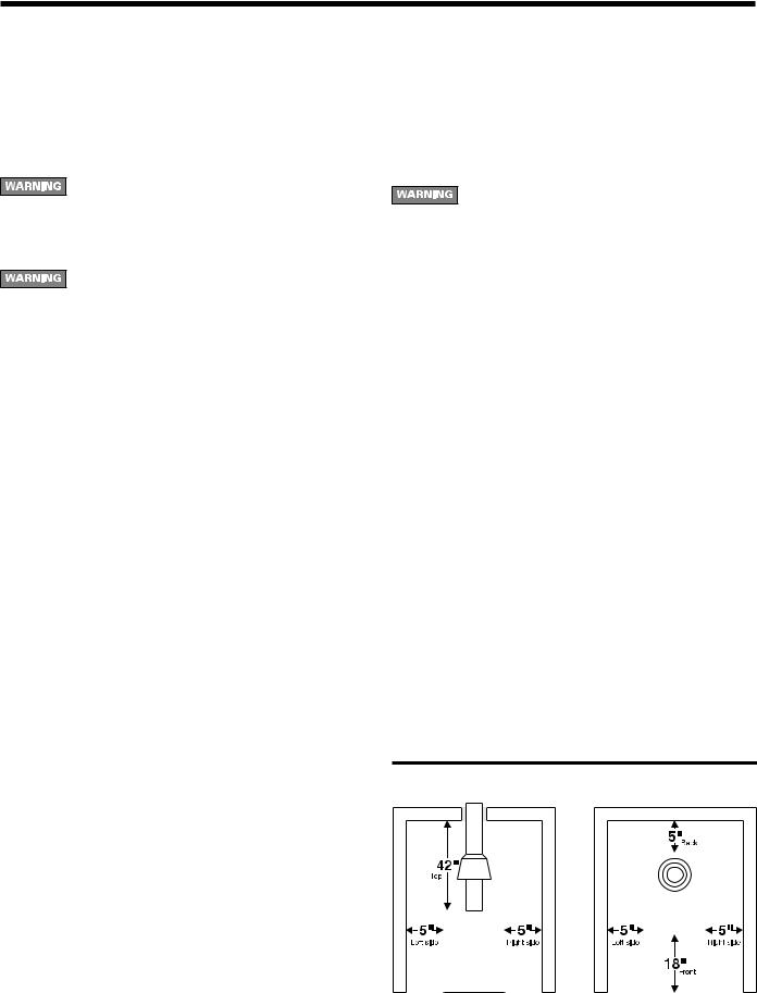
PFG-5 through PFG-7: Required minimum clearances to combustible surface in alcove installations (see below)
PFG 5 thru 7: Top 42” |
R. Side 5” |
Front: Alcove 18” |
Rear 5” |
L. Side 5” |
|
PFG-8: Required minimum clearances to combustible surfacel in alcove installations
PFG 8: Provide minimum 24” between jacket and any combustible wall(s). Provide minimum 48” between jacket top and combustible ceiling or surface above the boiler.
Install in a space large in comparison to size of boiler.
Clearances from piping materials to combustible surfaces
•Single wall vent pipe must be at least 6 inches from combustible surface.
•Type “B” double wall metal vent pipe - refer to vent manufacturer’s recommendation for clearances to combustible surface.
•Hot water pipes must be at least ½” from combustible surface.
Note |
Minimum clearances from combustible |
|
surfaces for models PFG-5 through PFG-7 |
PFG Series 7 Gas-fired Water Boiler — Boiler Manual
Chimney or vent requirements
(also refer to Breaching erection, Page 12)
Venting must be installed according to Part 7,Venting of Equipment, of National Fuel Gas Code, ANSI Z223.1- latest edition and applicable building codes. Canadian installations must comply with CAN/CSA B149.1 or .2 Installation Codes.
Minimum chimney or vent sizes are on page 22.A chimney or vent without a listed cap should extend at least 3 feet above the highest point where it passes through a roof of a building and at least 2 feet higher than any portion of a building within a horizontal distance of 10 feet. A chimney or vent must not extend less than those distances stated above.
A lined chimney is preferred and must be used when required by federal, provincial, territorial, state or local building codes. Vitreous tile linings with joints which prevent the retention of moisture and linings made of corrosion-resistant materials are best. Advice for flue connections and chimney linings can usually be obtained from the local gas utility. Type “B” double wall metal vent pipe or single wall vent pipe may be used as a liner.
Cold masonry chimneys, also known as outside chimneys, typically have one or more walls exposed to outside air.
When any atmospheric gas-fired boiler with automatic vent damper is vented through this type of chimney, the potential exists for condensation to occur. Condensation can damage a masonry chimney.
Weil-McLain recommends the following to prevent possible damage:
1.Line chimney with corrosion-resistant metal liner such as AL29-4C® single wall stainless steel or B-vent. Size liner per National Fuel Code ANSI Z223.1-latest edition.
2.Provide drain trap to remove any condensate.
Inspect existing chimney or vent before installing boiler. Failure to clean or replace perforated pipe or tile lining will cause severe injury or death.
Do not alter boiler draft hood or place any obstruction or non-approved damper in the breeching of vent system. CSA certification becomes void. Flue gas spillage and carbon monoxide emissions will occur causing severe personal injury or death.
Where two or more gas appliances vent into a common chimney or vent, equivalent area should be at least equal to the area of the vent outlet on the largest appliance plus 50 percent of the area of the vent outlet on the additional appliance(s).
When removing boiler from common venting system
Failure to follow all instructions listed below can cause flue gas spillage and carbon monoxide emissions, resulting in severe personal injury, death or substantial property damage.
At the time of removal of an existing boiler, the following steps shall be followed with each appliance remaining connected to the common venting system placed in operation, while the other appliances remaining connected to the common venting system are not in operation.
a.Seal any unused openings in the common venting system.
b.Visually inspect the venting system for proper size and horizontal pitch and determine there is no blockage or restriction, leakage, corrosion and other deficiencies which could cause an unsafe condition.
c.Insofar as is practical, close all building doors and windows and all doors between the space in which the appliances remaining connected to the common venting system are located and other spaces of the building. Turn on clothes dryers and any appliance not connected to the common venting system. Turn on any exhaust fans, such as range hoods and bathroom exhausts, so they will operate at maximum speed. Do not operate a summer exhaust fan. Close fireplace dampers.
d.Place in operation the appliance being inspected. Follow the lighting instructions. Adjust thermostat so appliance will operate continuously.
e.Test for spillage at the draft hood relief opening after 5 minutes of main burner operation. Use the flame of a match or candle, or smoke from a cigarette, cigar or pipe.
f.After it has been determined that each appliance remaining connected to the common venting system properly vents when tested as outlined above, return doors, windows, exhaust fans, fireplace dampers, and any other gasburning appliance to their previous conditions of use.
g.Any improper operation of the common venting system should be corrected so the installation conforms with the National Fuel Gas Code,ANSI Z223.1-latest edition.When resizing any portion of the common venting system, the common venting system should be resized to approach the minimum size as determined using the appropriate tables in Part 11 in the National Fuel Gas Code, ANSI Z223.1-latest edition.
Canadian installations must comply with CAN/CSA B149.1 or B149.2 Installation Code.
Part Number 550-110-641/0605

PFG Series 7 Gas-fired Water Boiler — Boiler Manual
Boiler foundation
Never install boiler on combustible flooring or carpeting, even if a concrete or aerated foundation is used. Severe personal injury, death or substantial property damage can result.
1.See Figure 1. A level concrete or solid brick pad is required if:
a)There is a possibility of the floor becoming flooded.
b)Non-level conditions exist.
2.An aerated boiler foundation is recommended if any of the following conditions exist:
a)Electrical wiring or telephone cables buried in the concrete floor of the boiler room.
b)Concrete floor is “green.”
c)There is a history of the floor becoming flooded.
d)Water is channeled under the concrete.
Figure 1 Boiler foundation
Part Number 550-110-641/0605
Placing the boiler
1.Remove boiler from shipping pallet. Do not drop boiler or bump jacket on floor or pallet.
2.Level boiler so that the built-in air separation will work correctly. Shim legs if necessary. Do not alter legs.
3.Remove front jacket door and burner access panel. Unscrew access panel screws, remove and discard shipping washers, and reinstall screws.
4.Check for proper orifice sizing from charts below.
Proper orifices must be used. Failure to do so will cause severe personal injury, death or substantial property damage.
5. Level and straighten the burners.
Burners must be seated properly in locating slots with their openings facing up. Gas orifices must inject down the center of the burner. Failure to properly seat burners will result in severe personal injury, death or substantial property damage.
6. Reinstall access panel.
Residential garage installation
Install boiler so burners are at least 18 inches above the floor.
Hydrostatic pressure test
Pressure test before attaching gas piping or electrical supply.
1.Plug any necessary boiler tappings or openings.
2.Connect water supply. Fill boiler and purge all air. Test at 45 psi for more than 10 minutes.
Do not leave boiler unattended. A cold water fill could expand and cause excessive pressure, resulting in severe personal injury, death or substantial property damage.
3. Check for maintained gauge pressure and leaks. Repair if found.
Leaks must be repaired at once. Failure to do so can cause boiler damage, resulting in substantial property damage.
Do not use petroleum-based sealing compounds in boiler system. Severe damage to boiler will result, causing substantial property damage.
4. Drain boiler and remove testing plugs.
PFG Series 7 Gas-fired Water Boiler — Boiler Manual
4. Expansion tank installations.
•
•
a)Closed type expansion tanks - connect from the ¾” N.P.T. expansion tank tapping on the left end section (located just behind the supply outlet tapping) to the expansion tank using ¾” N.P.T. piping. Any horizontal expansion tank piping must pitch upward toward the tank at least 1 inch for each 5 feet of piping.
b)Diaphragm type expansion tank - may be located anywhere in the system, preferably near the boiler.
A manual or automatic type air vent must be installed in the ¾”N.P.T. tapping when a diaphragm type tank is used.
The most common cause of lime deposits in boilers is inadequate expansion tank volume. If the expansion tank is too small, system water is lost from the relief valve and make-up water is added through the fill valve. Eventual section failure will result.
5.Connect the system supply piping to the supply outlet tapping on the left end of the boiler. See Figure 2a for minimum pipe size.
6.Connect the system return piping to the return tapping on the right end of the boiler. See Figure 2a for minimum pipe size.
•Discharge line must pitch downward from the valve 7. Install drain valve provided with boiler on left side. The installer
and terminate at least 6”above the floor drain where any discharge will be clearly visible.
•The discharge line shall terminate plain, not threaded, with a material serviceable for temperatures of 375 °F or greater.
•Do not pipe the discharge to any place where freezing could occur.
•No shutoff valve shall be installed between the relief valve and boiler, or in the discharge line. Do not plug or place any obstruction in the discharge line.
•Failure to comply with the above guidelines could result in failure of the relief valve to operate, resulting in possibility of severe personal injury, death or substantial property damage.
•Test the operation of the valve after filling and pressurizing system by lifting the lever. Make sure the valve discharges freely. If the valve fails to operate correctly, replace it with a new relief valve.
2.Install pressure-temperature gauge in tapping provided in left end section.
3.This boiler is for forced hot water circulation only. The circulator and expansion tank must be selected and sized according to the design requirements of the system.
a)Size and install circulator. Can be installed on supply or return piping
b)Size expansion tank to handle the volume of water in the system.
must provide a drain cock to drain the right (return) side of the boiler and its connecting piping. The drain cock on the left side of the boiler will not fully drain the right side.
8.Low water cut off:
a)Must be installed on any PFG boiler if the boiler is located above radiation level.
b)Must be installed on all PFG-8 boilers to meet ASME specifications (low water cut-off not supplied by Weil-McLain).
c)May be required by certain state, local or territorial codes or insurance companies.
If a low water cut-off is required, use a control designed especially for water installations. An electrode probe type low water cut-off may be located in a tee in the supply line above the boiler.
9.If the system is to be ASME inspected and approved, an additional high temperature limit is needed. Purchase and install the control in the supply outlet piping to the boiler.
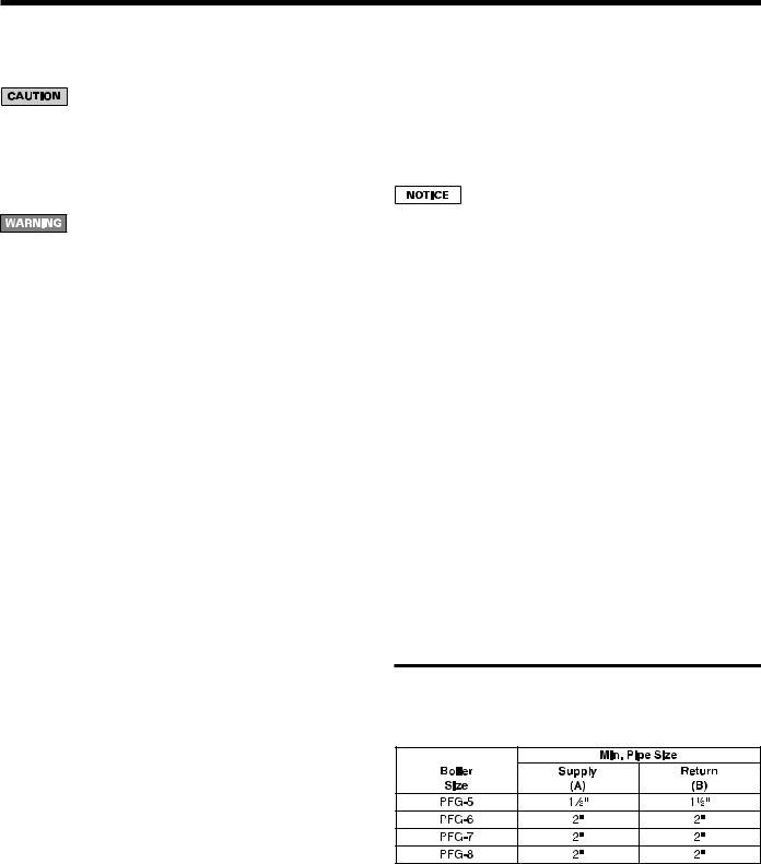
Figure 2a Minimum recommended pipe sizes
(Supply and return sizes refer to minimum size of pipe connected to the boiler for 20°F temperature drop between supply and return.)
Part Number 550-110-641/0605
PFG Series 7 Gas-fired Water Boiler — Boiler Manual
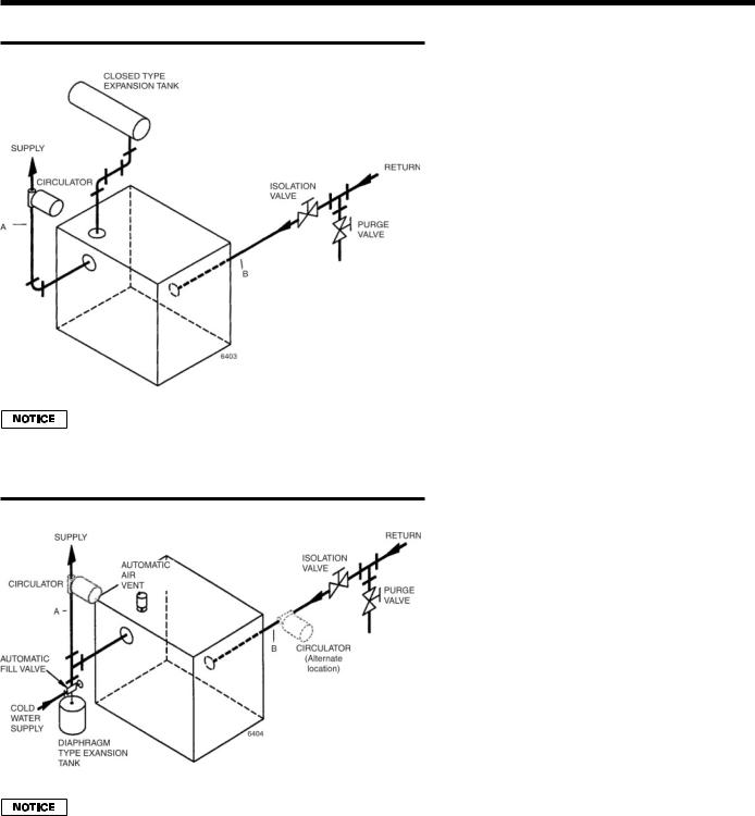
Figure 2b Piping – Closed type expansion tank
Use circulators or zone valves in each circuit for multiple circuit applications.
Figure 2c Piping – Closed diaphragm type expansion tank
Use circulators or zone valves in each circuit for multiple circuit applications.
Multiple zoning
1.Zone valves:
a)Refer to zone valve manufacturer’s literature for wiring and application. A separate transformer is required to power zone valves.
b)Provide balancing valves to adjust the flow so it is about the same in each zone.
2.Circulators:
a)Zoning with circulators requires a relay for each circuit.
b)Install flow control valves to prevent gravity circulation.
c)Provide balancing valves to adjust the flow so it is about the same in each zone.
d)Size common return and supply piping for total flow of all circulators.
Filling the system
1.Close manual air vents, drain cock, and automatic air vent, if used.
2.Fill to correct system pressure. Correct pressure will vary with each application. Residential systems are often designed for 12 pounds cold fill pressure.
3.Open automatic air vent one turn, if used.
4.Air must be vented for the system. Air in the system can interfere with water circulation and cause improper heat distribution.
a)Open manual water feed valve.
b)Starting on the lowest floor, open the air vents one at a time until water squirts out. Close vent.
c)Repeat with remaining vents.
d)Close manual water feed valve when correct boiler pressure is reached.
5.To purge air from system, install isolation valve in return piping.
a)Connect a garden hose to the purge valve located above the isolation valve.
b)Close isolation valve. Open purge valve.
c)Open hand water feed valve and allow system to purge all air. If system has more than one circuit, purge each circuit separately by opening each balancing valve one at a time.
d)Close purge valve.
e)Open isolation valve.
f)Fill the system to the correct pressure.
6.Keep the system filled by occasionally opening the air vents as in Step 4 above. Add water to make up system pressure.
Part Number 550-110-641/0605

PFG Series 7 Gas-fired Water Boiler — Boiler Manual
Bypass piping
Bypass piping is not normally required on any baseboard system.
Bypass piping should be used for the following installations. (Bypass, supply, and return piping should be same size.)
1.Use the piping shown in Figure 3 to protect:
•radiant panels, plaster, etc. from high temperature water supplied from boiler, or
•boiler from condensation caused by low temperature water returned from system.
2.Use the piping shown in Figure 4 to protect boiler from condensation formed by low water temperature returned from large water content converted gravity systems, etc.
Figure 3
Figure 4
Part Number 550-110-641/0605
 Loading...