

Weider WESY68631 Owner’s Manual
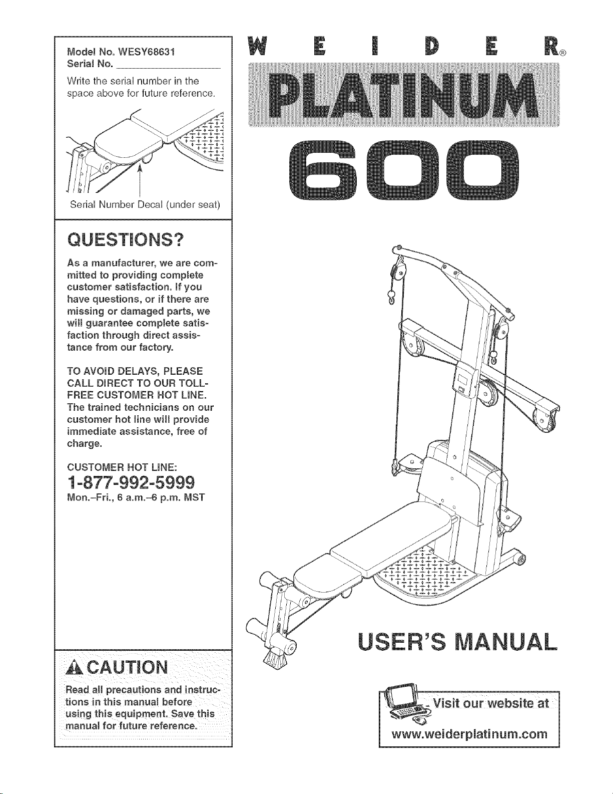
ModelNo.WESY68631
SedalNo.
WritetheseriaUnumberinthe
spaceaboveforfuturereference,
SedaUNumberDecaU(underseat)
Asamanufacturer,wearecom-
mittedto providingcomptete
customersatisfaction,Ifyou
havequestions,or ifthereare
missingordamagedparts,we
willguaranteecompletesatis-
factionthroughdirectassis-
tancefromourfactory.
®
TOAVOIDDELAYS,PLEASE
CALLDIRECTTOOURTOLL-
FREECUSTOMERHOTLINE.
Thetrainedtechniciansonour
customerhottinewill provide
immediateassistance,freeof
charge.
CUSTOMERHOTLINE:
1°877°992°5999
Mon.=Fd., 6 a.m.=6 p.m. MST
Read all precautions and instruc-
tions in this manuat before
using this equipment. Save this
manual for future reference.
TABLE OF CONTENTS
WARNING DECAL PLACEMENT ............................................................. 3
HMPORTANT PRECAUTHONS ................................................................ 4
BEFORE YOU BEGIN ...................................................................... 5
ASSEMBLY ............................................................................... 6
UPPER CABLE ADJUSTMENT .............................................................. 14
ADJUSTMENTS .......................................................................... 15
CABLE DHAGRAM ......................................................................... 18
TROUBLESHOOTHNG ..................................................................... 19
EXERCISE GUiDELiNES .................................................................. 20
ORDERING REPLACEMENT PARTS .................................................. Back Cover
LiMiTED WARRANTY .............................................................. Back Cover
Note: A PART iDENTiFiCATiON CHART and a PART LiST/EXPLODED DRAVVHNGare attached in the center of
this manual, Remove the PART iDENTiFiCATiON CHART and PART LiST/EXPLODED DRAWING before begin-
ning assembly,
WELDER is a registered trademark of iCON Health & Fitness, Inc,
2
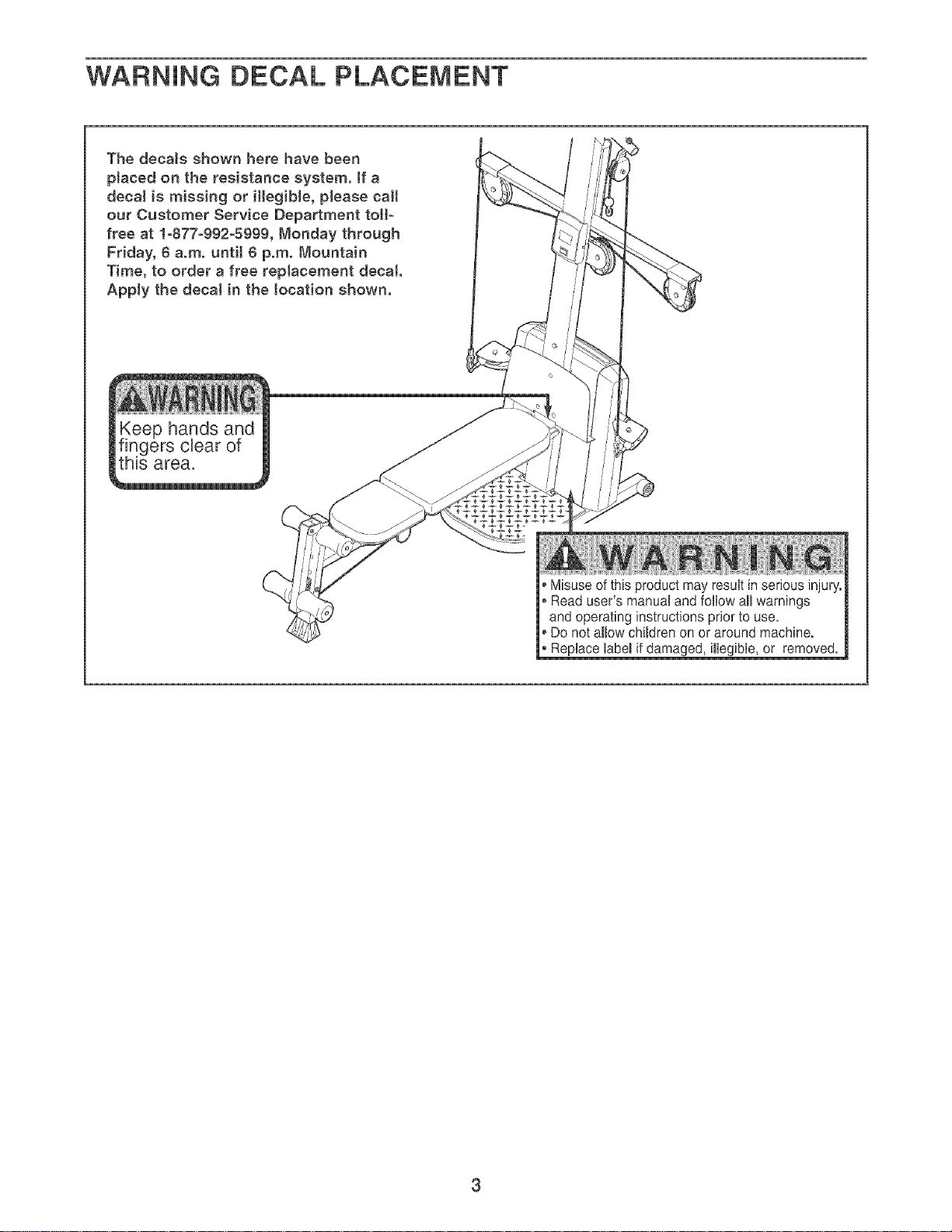
WARNING DECAL PLACEMENT
Misuse of this product may result in serious injury.
, Read user's manual and follow aHwarnings
and operating instructions prior to use.
Do not allow children on or around machine.
• Replace mabemif damaged, illegible, or removed.
3

iMPORTANT PRECAUTIONS
AWARN! NG: Toreducethedskofserious_ni.ry,readthere,owingimportontpreeaut_ons
before using the resistance system.
1. Read all instructions in this manual before
using the resistance system. Use the resist-
ance system onJy as described in this manual
2. it is the responsibility of the owner to ensure
that all users of the resistance system are
adequateJy informed of aJl precautions.
3. The resistance system is intended for home
use only. Do not use the resistance system in
any commercial, rental, or institutional setting.
4. Use the resistance system only on a level 13. Always disconnect the lat bar from the high
surface. Cover the fJoor beneath the resist- cables when performing an e×ercise that
ance system to protect the fJoor, does not require it.
5. Make sure that aH parts are properly tight-
ened each time the resistance system is
used. Replace any worn parts immediately.
6. Keep children under 12 and pets away from 15. Make sure that the cables remain on the pul-
the resistance system at aH times, leys at aH times, if the cables bind as you are
7. Keep hands and feet away from moving parts, that the cables are on the pulleys.
11. Pull on the lower cable only while sitting on
the bench or standing on the base pJate. Pull
on the high cabJes only while sitting on the
bench, with the seat in one of the three posi-
tions closest to the upright base, or white
standing on the base pJate.
12. The resistance system is designed to be
used with the incJuded resistance. Do not
use the resistance system with any other
type of resistance.
14. Make sure the storage knob is in place and
fully tightened each time the resistance sys-
tem is used.
e×ercising, stop immediately and make sure
8. Always wear athletic shoes for foot protec-
tion while e×ercising.
9. The resistance system is designed to sup- 17. if you feel pain or dizziness whiJe e×ercising,
port a ma×imum user weight of 300 pounds, stop immediately and begin cooling down.
10. The crossbar on the top frame is not
designed to be used for pull-up e×ercises. Do
not hang on the crossbar.
16. Do not pull on the cables while the resist-
ance Jevel is being adjusted.
,_ WAR NiNG: Beforebeginningthisoranye×ereiseprogram,cons,,ltyourphysician.This
is especially important for persons over the age of 35 or persons with pre-existing health problems.
Read aH instructions before using, iCON assumes no responsibility for personal injury or property
damage sustained by or through the use of this product.
4
BEFORE YOU BEGIN
Thank you for sebcting the innovative WELDER<_
PLATINUM 600 resistance system, The resistance sys-
tem offers a sebction of stations designed to develop
every major muscb group of the body, Whether your
goal is to tone your body, build dramatic muscle size
and strength, or improve your cardiovascular system,
the resistance system will help you to achieve the spe-
cific results you want,
For your benefit, read this manuaJ carefully before
using the resistance system, if you have questions
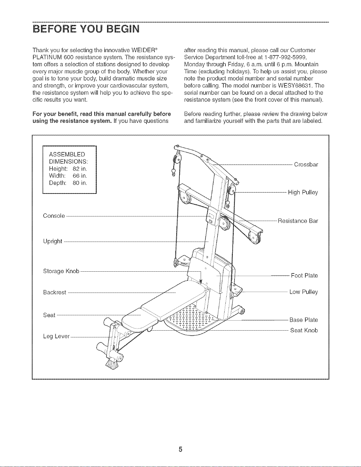
ASSEMBLED
DiMENSiONS:
Height: 82 in,
Width: 66in_
Depth: 80 in,
Console
after reading this manual, phase call our Customer
Service Department toDfree at 1-877-992-5999,
Monday through Friday, 6 a,m, until 6 p,m, Mountain
Time (excluding holidays), To help us assist you, please
note the product model number and serial number
before calling, The model number is WESY68631, The
serial number can be found on a decal attached to the
resistance system (see the front cover of this manual),
Before reading further, please review the drawing below
and familiarize yourself with the parts that are labeled,
Crossbar
High Pulley
Resistance Bar
Upright
Storage Knob
Backrest
Seat
Leg Lever
Foot Hate
Low Pulley
Base Hate
Seat Knob
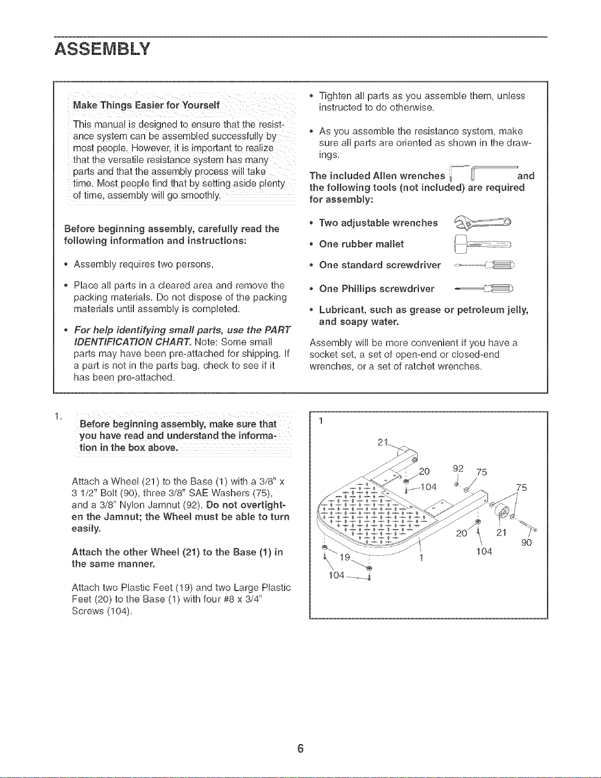
MakeThings Easier for Yourself
Tighten all parts as you assemble them, unless
instructed to do otherwise.
This manual is designed to ensure that the resist-
ance system can be assembUed suceessfuUiy by
most peopb, However, it is important to realize
that the versatile resistance system has many
parts and that the assembly process will take
time, Most people find that by setting aside plenty
of time. assembly wiUigo smoothly.
Before beginning assembly, carefully read the
following information and instructions:
Assembly requires two persons,
Place all parts in a cleared area and remove the
packing materials, Do not dispose of the packing
materials until assembly is completed,
• For help identifying small parts, use the PART
IDENTIFICATION CHART. Note: Some small
parts may have been pre-attached for shipping, if
a part is not in the parts bag, check to see if it
has been pro-attached,
, As you assemble the resistance system, make
sure all parts are oriented as shown in the draw-
ings,
The included AHen wrenches ii-- _and
the following tools (not included} are required
for assembly:
Two adjustable wrenches
One rubber mallet
One standard screwdriver _._
• One Philtips screwdriver _C__
Lubricant, such as grease or petroleum jelly,
and soapy water.
Assembly wiii be more convenient if you have a
socket set, a set of open-end or closed-end
wrenches, or a set of ratchet wrenches,
Before beginning assembly, make sure that
you have read and understand the informa,
tion in the box above.
Attach a Wheel (21) to the Base (1) with a 3/8" x
3 1/2" Bolt (90), three 3/8" SAE Washers (75),
and a 3/8" Nylon Jamnut (92). Do not overtight-
en the Jamnut; the Wheel must be able to turn
easily.
Attach the other Wheel (21} to the Base (!} in
the same manner.
Attach two Plastic Feet (19) and two Large Plastic
Feet (20) to the Base (1) with four #8 x 3/4"
Screws (104).
92 75
75
21
90
104
104 ___j.
6

Attach the Upright (3) to the Base (1) with two
2. 2
3/8" x 2 3/4" Carriage BoUts(88), two 3/8" x 3"
BoUts(87), and four 3/8" NyUonLocknuts (73) as
shown. Note: This step will be easier to com-
plete if the Upright and Base are tipped on
their sides.
73
i i i
i °
'° ii
/
//
87
73
Attach the Foot Hate (4) to the Upright (3) with
three 3/8" x 2 3/4" Carriage BoUts(88), three 3/8"
SAE Washers (75), and three 3/8" NyUon
Locknuts (73).
88
88
75
73
73
75
7
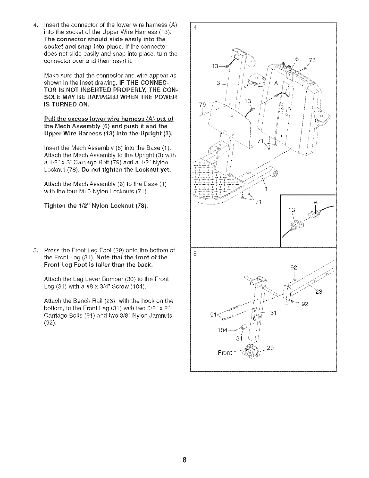
insert the connector of the lower wire harness (A)
4, 4
into the socket of the Upper Wire Harness (13),
The connector shouJd sJide easily into the
socket and snap into pJace, if the connector
does not slide easily and snap into place, turn the
connector over and then insert it,
Make sure that the connector and wure appear as
shown in the inset drawing, mFTHE CONNEC-
TOR (S NOT (NSERTED PROPERLY, THE CON-
SOLE MAY BE DAMAGED WHEN THE POWER
mSTURNED ON.
PuJl the excess (ower wire harness (A_ out of
the Mech Assembly (6} and push it and the
U__per Wire Harness (J3) into the Up_
insert the Mech Assembly (6) into the Base (1),
Attach the Mech Assembly to the Upright (3) with
a 1/2" x 3" Carriage Bolt (79) and a 1/2" Nylon
Locknut (78), Do not tighten the Locknut yet.
6 78
13
Attach the Mech Assembly (6) to the Base (1)
with the four MIO Nylon Locknuts (71),
Tighten the 1/2" Nylon Locknut (78}.
Press the Front Leg Foot (29) onto the bottom of
the Front Leg (31), Note that the front of the
Front Leg Foot is tatter than the back.
Attach the Leg Lever Bumper (30) to the Front
Leg (31) with a #8 x 3/4" Screw (104),
Attach the Bench Rail (23), with the hook on the
bottom, to the Front Leg (31) with two 3/8" x 2"
Carriage Bolts (91) and two 3/8" Nylon Jamnuts
(92),
1
71 A
13
92
8
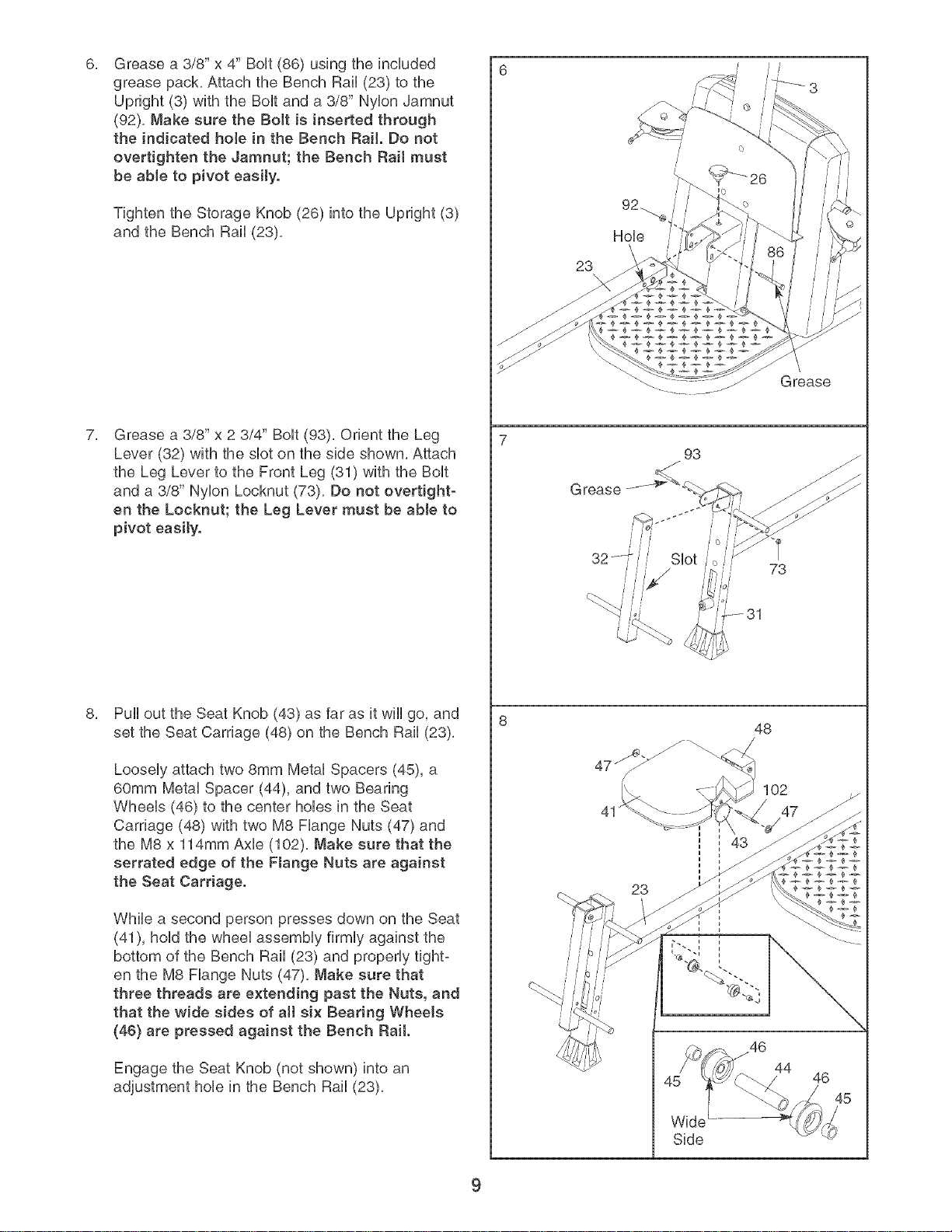
Grease a 3/8" x 4" BoUt(86) using the incUuded
grease pack, Attach the Bench Rail (23) to the
Upright (3) with the BoUtand a 3/8" NyUonJamnut
(92), Make sure the BoJt is inserted through
the indicated hole in the Bench Rail. Do not
overtighten the Jamnut; the Bench Rail must
be able to pivot easity.
Tighten the Storage Knob (26) into the Upright (3)
and the Bench Rail (23),
Grease a 3/8" x 2 3/4" BoUt(93), Orient the Leg
Lever (32) with the sUoton the side shown, Attach
the Leg Lever to the Front Leg (31) with the BoUt
and a 3/8" NyUonLocknut (73), Do not overtight-
en the Locknut; the Leg Lever must be able to
pivot easily.
23
32t€// Slot //o /
///
G rease
io
t
73
Pull out the Seat Knob (43) as far as it wHUgo, and
set the Seat Carriage (48) on the Bench Rail (23),
LooseUyattach two 8mm MetaUSpacers (45), a
60mm MetaUSpacer (44), and two Bearing
WheeUs (46) to the center hoUesin the Seat
Carriage (48) with two M8 FUange Nuts (47) and
the M8 x 114mm Axle (102), Make sure that the
serrated edge of the Flange Nuts are against
the Seat Carriage.
While a second person presses down on the Seat
(41), hold the wheel assembly firmly against the
bottom of the Bench Rail (23) and properly tight-
en the M8 Flange Nuts (47), Make sure that
three threads are extending past the Nuts, and
that the wide sides of aH six Bearing WheeJs
(46} are pressed against the Bench Rait.
/
48
102
47
23
Engage the Seat Knob (not shown) into an
adjustment hole in the Bench Rail (23),
44
46
_5
Side
9
 Loading...