

Page 1
SCA-05 Fieldbus
Communication Kit
Kit de Comunicación
Fieldbus para SCA-05
Kit de Comunicação
Fieldbus para SCA-05
Installation Guide
Guia de Instalación
Guia de Instalação
Page 2
English
INST ALLATION GUIDE
SCA-05 Fieldbus Communication Kit
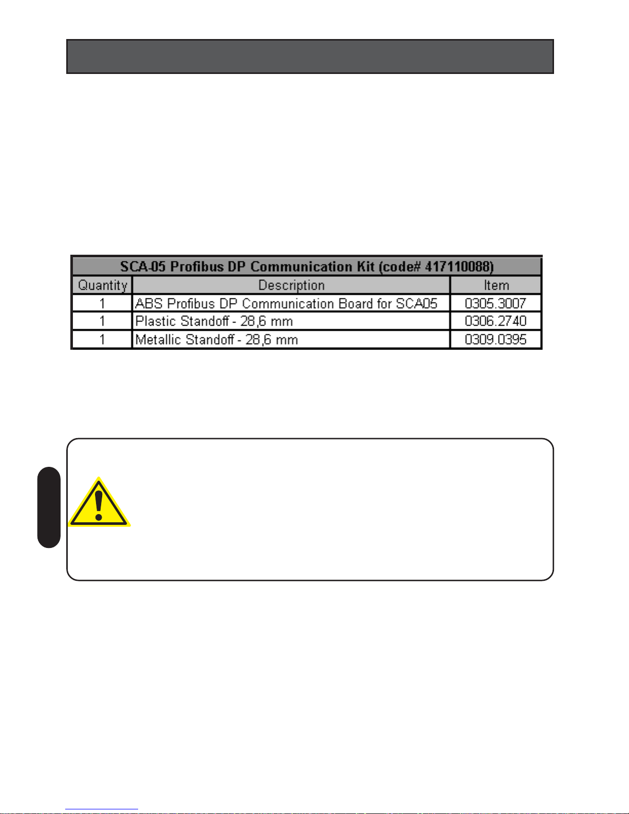
I – KIT DESCRIPTION
Profibus DP communication kit for the SCA-05 Servo Drive.
Kit contents:
II – SAFETY NOTICES
ATTENTION!
• Switch off the SCA-05 Servo Drive before installing the Fieldbus
Communication Kit.
• The electronic boards have components that are susceptible to
electrostatic discharge. Never touch any of the electrical components
or connectors without following the proper grounding procedures. If it
is necessary to do so, touch the grounded metallic frame or use a
suitable grounded wrist strap.
01
Page 3
VIEW "X"
VIEW "X"
MOVEMENT
DIRECTION
C
D
A
A
B
B
1
2
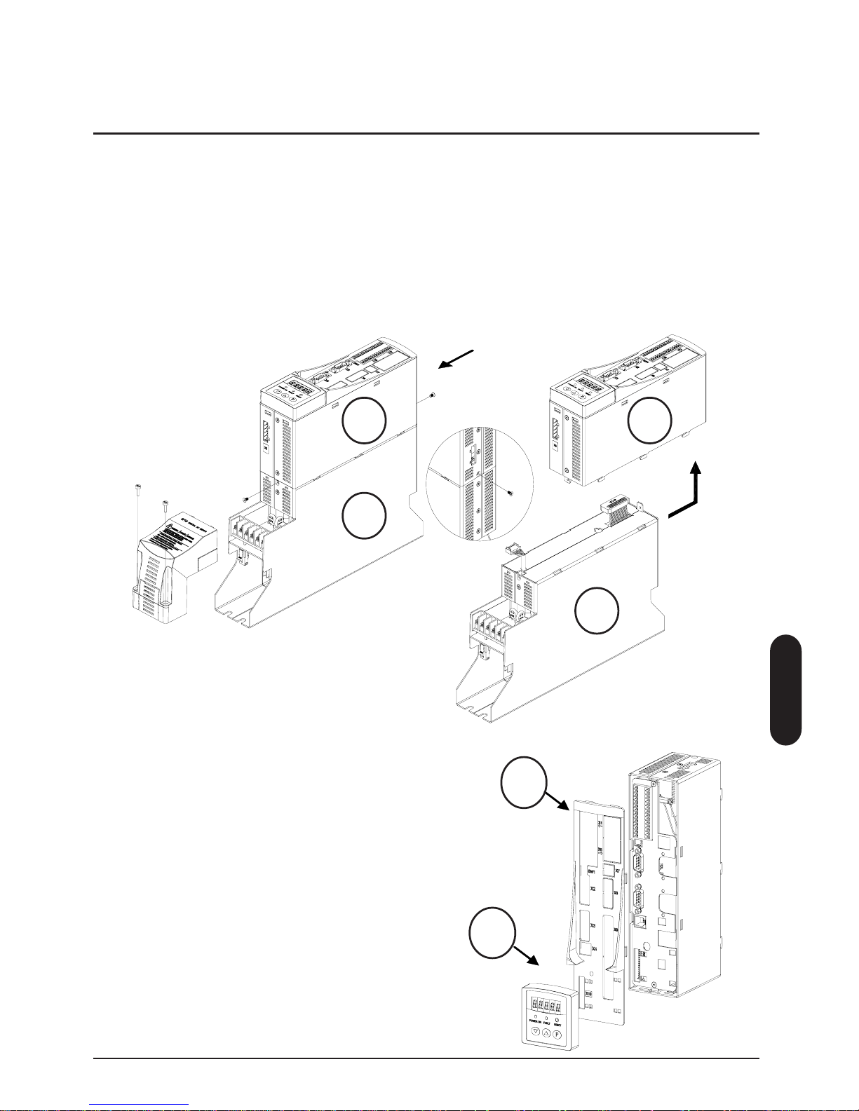
III - COMMUNICA TION KIT INSTALLA TION
For installing the communication kit proceed according to the following steps:
English
Step 1: Disconnect all the cables and connectors from the front, top and bottom
parts of the control module (A).
Step 2: Detach the control module from the power module (B) - Loose the screws
indicated in the figure, and detach the modules performing two movements (see
the arrows).
Step 3: Disconnect the cables that interconnect the control module to the power
module.
Step 4: Remove the keypad from the control
module (C) by pulling it (hold the module by
its sides).
Step 5: Remove the plastic cover (D).
Detach the fasteners around the control
module and pull to remove the plastic cover .
Extract the X9 connector protection from the
removed plastic cover .
02
Page 4

E
Step 7: Remove the screw from the position
indicated by the arrow and insert the metallic
and plastic standoffs into the SCA-05 control
board holes, as illustrated in the figure. Keep
the screw for later use.
Observe the correct orientation for the plastic
standoff (figure det ail).
English
Step 6: Loose the screws indicated in the figure
to remove the control module metallic lateral (E).
It allows the access to the SCA-05 control board
(F).
Step 8: Remove the mounting screws located
around the DB9 connector from the
communication board (figure detail).
XC12
Once the Profibus DP communication kit is installed, reassembly the control module
and reconnect it to the power module.
For a complete description of the SCA-05 Servo Drive operation using Profibus
DP communication protocol, refer to SCA-05 User’s Guide
Step 9: Attach the communication board to
the product carefully, aligning the pins bus
with the control board XC12 connector and
seating the board properly on the standoffs.
Step10: Securely tighten the communication
board to the metallic standof f with the screw you
removed earlier . Replace the mounting screws
around the communication board DB9 connector
fastening them to the product metallic cover.
NOTE
Remember to reconnect all the cables removed during the kit
installation before proceeding with the SCA-05 Servo Drive operation.
F
03
Page 5

04
Español
GUIA DE INSTALACIÓN
Kit de comunicación Fieldbus para SCA-05
I – DESCRIPCION DEL KIT
Kit de comunicación Profibus DP para servoconvertidor SCA-05.
Este kit contiene:
II – INFORMACIONES DE SEGURIDAD
ATENCIÓN!
• Desconecte el servoconvertidor SCA-05 antes de instalar el kit de
comunicación fieldbus.
• Las tarjetas electrónicas utilizan componentes sensibles a descargas
electrostaticas. No toque directamente sobre los componentes o
conectores. Caso necesario, tocar antes en la carcaza metálica
aterrizada o utilice pulsera de aterrizamiento adecuada.
Page 6

05
VISTA "X"
VISTA "X"
DIRECCIÓN
DEL MOVIMIENTO
D
C
A
A
B
B
1
2
III - PROCEDIMENTO PARA INSTALACIÓN DEL KIT DE
COMUNICACIÓN
Para la correcta instalación del kit de comunicación, siga los pasos siguientes:
Paso 1: Desconecte todos los cables y conectores que están conectados a la
parte frontal, superior e inferior del módulo de control (A).
Paso 2: Separe el módulo de control del módulo de potencia (B). Solte los tornillos
indicados en la figura y luego desencajar los módulos, realizando dos movimientos
conforme indicado por las flechas.
Paso 3: Desconecte los cables que conectan el módulo de control al módulo de
potencia.
Paso 4: Con el módulo de control libre,
saque la HMI (C), colgando por las laterales
y haciendo fuerza hacia el sentido frontal
del producto.
Paso 5:Saque la tapa plástica (D).
Desencaje los fijadores localizados en el
costado del módulo de control. Con la tapa
plástica, saque la protección de encaje X9.
Español
Page 7

Paso 7: Saque los tornillos de la posición
indicada por la flecha y en seguida fije los
espaciadores metálico y plástico en los
agujeros existentes en la tarjeta de control del
SCA-05, conforme indicado en la figura.
Para el espaciador plástico, observe el lado
que debe quedar volcado para fuera (detalle
de la figura).
Paso 6: Solte los tornillos indicados en la figura
para sacar la lateral metálica (E) del módulo de
control.
Esto permitirá el acceso a la tarjeta de control (F)
del SCA-05.
XC12
Para la descripción de la operación del servoconvertidor SCA-05 en red Profibus
DP, consulte el manual del equipamiento.
Paso10: Usando el tornillo sacado de la tarjeta
de control, fije la tarjeta de comunicación al
espaciador metálico. Después, coloque
nuevamente los tornillos de fijación en las laterales
del conector DB9 de la tarjeta de comunicación,
prendiendo este en la frente metálica del producto.
NOTA
No olvidarse de conectar todos los cables que fueron sacados durante
la instalación.
F
E
Paso 8: En la tarjeta de comunicación recibida
en el kit, saque los tornillos de fijación presentes
al lado del conector DB9 (detalle de la figura).
Paso 9: Fije la tarjeta de comunicación en el
producto con cuidado, alineando el
barramiento de pinos el el conector XC12 de
la tarjeta de control y prendiendo
adecuadamente en el espaciador plástico.
Una vez instalado el kit de comunicación Profibus DP, arme el módulo de control
y conecte nuevamente al módulo de potencia.
Español
06
Page 8

07
GUIA DE INSTALAÇÃO
Kit de comunicação Fieldbus para SCA-05
Kit de comunicação Profibus DP para servoconversor SCA-05.
Este kit contém:
II – INFORMAÇÕES DE SEGURANÇA
ATENÇÃO!
• Desligue o servoconversor SCA-05 antes de instalar o kit de
comunicação fieldbus.
• Os cartões eletrônicos possuem componentes sensíveis a
descargas eletrostáticas. Não toque diretamente sobre componentes
ou conectores. Caso necessário, toque antes na carcaça metálica
aterrada ou utilize pulseira de aterramento adequada.
I - DESCRIÇÃO DO KIT
Português
Page 9

Português
D
C
VISTA "X"
VISTA "X"
SENTIDO DO
MOVIMENTO
A
A
B
B
1
2
III - PROCEDIMENTO PARA INSTALAÇÃO DO KIT DE
COMUNICAÇÃO
Para a correta instalação do kit de comunicação, siga os passos a seguir:
Passo 1: Desconecte todos os cabos e conectores ligados na parte frontal, superior
e inferior do módulo de controle (A).
Passo 2: Separe o módulo de controle do módulo de potência (B). Solte os
parafusos indicados na figura e, em seguida, desencaixe os módulos, realizando
dois movimentos conforme indicado pelas setas.
Passo 3: Desconecte então os cabos que ligam o módulo de controle ao módulo
de potência.
Passo 4: Com o módulo de controle livre,
remova a IHM (C), segurando pelas laterais
e puxando no sentido frontal do produto.
Passo 5: Remova a frente plástica (D).
Desencaixe os prendedores localizados em
volta do módulo de controle. Com a frente
plástica, retire a proteção do encaixe X9.
Português
08
Page 10

E
Passo 7: Remova o parafuso da posição
indicada pela seta e em seguida fixe os
espaçadores metálico e plástico nas furações
existentes no cartão de controle do SCA-05,
conforme indicado na figura.
Para o espaçador plástico, observe o lado que
deve ficar voltado para fora (detalhe da figura)
Passo 6: Solte os parafusos indicados na figura
para remover a lateral metálica (E) do módulo
de controle.
Isso permitirá o acesso ao cartão de controle
(F) do SCA-05.
Passo 8: No cartão de comunicação recebido
no kit, remova os parafusos de fixação
presentes ao lado do conector DB9 (detalhe da
figura)
XC12
Uma vez instalado o kit de comunicação Profibus DP, monte o módulo de controle
e conecte novamente ao módulo de potência.
Para a descrição da operação do servoconversor SCA-05 em rede Profibus DP,
consulte o manual do equipamento.
Passo 9: Fixe o cartão de comunicação no
produto com cuidado, alinhando o
barramento de pinos no conector XC12 do
cartão de controle e prendendo
adequadamente no espaçadoor plástico.
Passo10: Usando o parafuso removido do
cartão de controle, fixe o cartão de comunicação
ao espaçador metálico. Em seguida, coloque
novamente os parafusos de fixação nas laterais
do conector DB9 do cartão de controle,
prendendo este na frente metálica do produto.
NOTA
Não esquecer de conectar todos os cabos removidos durante a
instalação.
F
Português
09
 Loading...