

Page 1

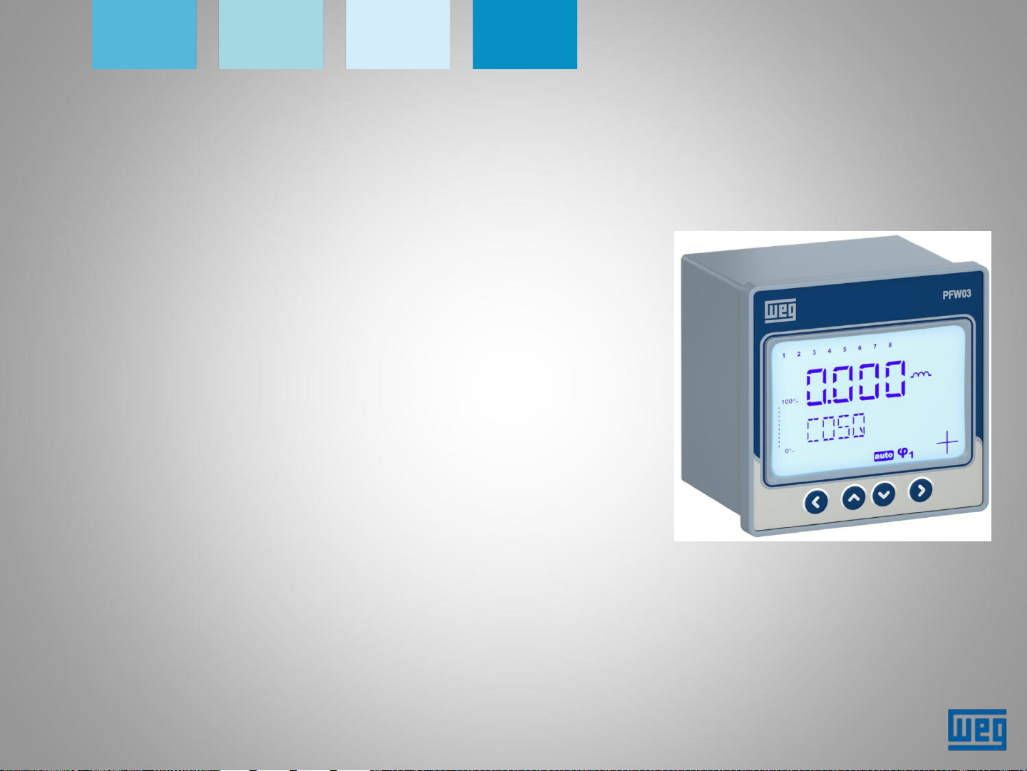
PFW03-M8
Automatic Power Factor Controller
Page 2
PFW03-M8
• It measures active (P) and reactive (Q) power
of the system to which it is connected;
• With the result of such measurement, it
activates capacitors in case it is necessary to
compensate reactive inductive loads;
• Through the front panel, you can easily access
all settings and readings of electrical quantities;
• One isolated RS485 port;
• Two output alarm relays;
Page 3

PFW03-M8
Main differences between the M8 model and the other PFWs
PFW03-M12/M24/T12/T24 PFW03-M8
Graphic LCD display Standard LCD Display
Dynamic monitoring of the capacitors --------
Several stage control modes Smart mode only
Automatic reading of the stages Manual selection of the stages
Stages with reactors/inductors Stages with capacitors only
Real time clock --------
Hourly, daily and monthly records No records
Fixed stages can be set No fixed stages
Demand measurement --------
Individual and total harmonic measurements
up to 51st order
Energy measurements --------
No setting of critical alarms Setting of critical alarms
Only total harmonic distortion
measurement up to 31st order
Page 4
PFW03-M8
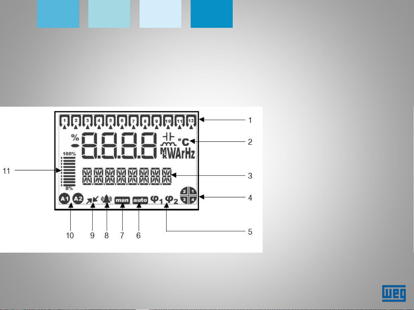
Description of the display functions
1) Stages;
2) Units and indicators;
3) Menu bar;
4) Quadrant indicator
5) Target cosφ;
6) Automatic mode;
7) Manual mode;
8) Alarm indicator;
9) Communication indicator;
10)Alarm relay indicator;
11)Indication bar of the stages
in operation in relation to
the total stages
Page 5
PFW03-M8
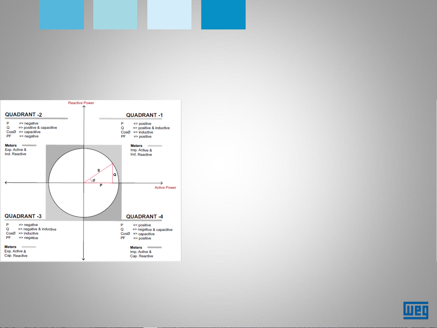
Description of the display functions
The direction of the energy flow is obtained by the
angular phase shift φ between voltage and current.
A positive value of the active/reactive power
indicates energy being consumed.
A negative value indicates energy being generated.
E.g.:
P= +10kWh, Q= +5kVAr => Quadrant-1
P= -10kWh, Q= +5kVAr => Quadrant-2
P= -10kWh, Q= -5kVAr => Quadrant-3
P= +10kWh, Q= -5kVAr => Quadrant-4
Page 6
PFW03-M8
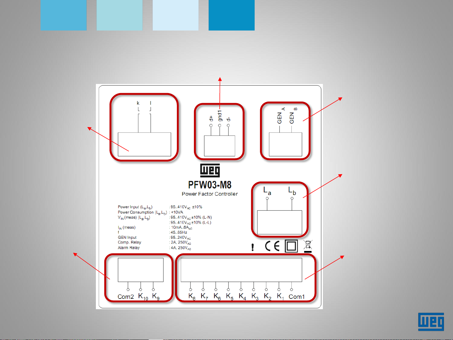
Connections
Current
measurement
input
RS485
terminals
GEN input
Power supply and
voltage
measurement
Terminals of the
alarm relays
Connection of
the stages
Page 7

PFW03-M8
Settings - 1st energization of the device
1) Language selection;
2) Selection of the connection type;
3) Input of the CT ratio;
3) Input of the PT ratio;
5) Selection of the cosφ1 type (ind or
cap);
6) Input of the target value of cosφ1;
7) Input of the Cosφ1 tolerance;
8) Selection of the stage structure
(1.1.1.1.1.2.2.2.1.2.4.4, Entr)
9) Input of the * Minimum stage value;
10) Setting the use or not of the ** Smart
Mode;
11) Settings are saved and the device is
started.
* If the selection of the stage structure is "Entr", the "MIN STEP" indication is not displayed;
Each stage is filled manually with power and voltage sequentially;
** If the selection of stages is "Entr", the Smart mode is automatically enabled, and the option menu
will not display screen 10.
Page 8

PFW03-M8
Settings – Basic
1)Main screen;
2)Settings menu;
3)Basic settings menu;
4)Connection type: this
menu contains 3
- CON3: Phase-neutral connection. For this
configuration, the current measurement and the voltage
measurement must be in the same phase
- CON2: Phase-phase connection. For connections
without neutral, the phase-phase current measurement
uses the measured phase and the next phase.
- CON1: Phase-phase connection. This is the type of
phase-phase connection where the two phases are used,
except for the phase in which the current is measured.
connection types:
CON1, CON2, CON3
Page 9

PFW03-M8
Settings – Basic
5) CT ratio: range from 1 to 5000;
6) PT ratio: range from 0.1 to 999.9;
7) Type of cosφ1: choose between inductive or capacitive;
8) Value of cosφ 1: setting range from 0.80 to 1.00;
9) Tolerance of cosφ1: cosφ permissible range from 0.00 to 0.20;
Page 10

PFW03-M8
Settings – Basic
10) Definition among 4 reactive load compensation structures:
- 1.1.1.1 All stages are equal. First-in, first-out (FIFO) is applied. The first stage enabled
will be the first stage to be disabled.
- 1.2.4.4: Stages are sized in the ratio 1.2.4.4. The first stage will always be the first
stage to be enabled or disabled. The other stages are used sequentially.
- 1.2.2.2: Stages are sized in the ratio 1.2.2.2. The first stage will always be the first
stage to be enabled or disabled. Different from the structure above, the other stages
follow the FIFO scheme (first-in, first-out).
- Entr: Stages are set manually. During operation in this structure, the "Smart Mode" is
enabled automatically. The device seeks the best correction with the least possible
number of stages enabled.
Page 11

PFW03-M8
Settings – Basic
11) When selecting modes 1.1.1.1, 1.2.4.4 or 1.2.2.2, the power of the smallest stage
is defined in this menu;
*** Stage power and voltage: If the structure is defined as "Entr", the power and
voltage of the existing stages will be set sequentially in this menu;
12) Any of the modes 1.1.1.1; 1.2.4.4 or 1.2.2.2 that is selected will enable the "Smart
Mode". In this option, the PFW will choose the smallest number of stages for the
correction and will apply the FIFO scheme (first-in, first-out).
NOTE: When you select the "Entr" structure, Smart Mode will be activated
automatically.
Page 12

PFW03-M8
Settings – Advanced
1) Settings menu;
2) Advanced settings;
3) If the "Generator" mode is "ON" when the GEN input is enabled, it is necessary to
set "cosφ 2 according to the following screens.
To enable the GEN input, a voltage signal of 95-240 VAC is required;
4) While the Manual mode is enabled, the "man" symbol will appear at the bottom of
the display in the main menu;
Note: For the PFW to work in the Automatic mode the "Manual" mode must be "Off";
5) Input of the number of stages to be used;
6) Target Cos 2 SIGN: setting of the type of cosφ 2 (induct. or capac.);
Page 13

PFW03-M8
Settings – Advanced
7) Input of the value of cosφ 2;
8) Setting of the tolerance range of cosφ 2 - value between 0.00 and 0.20;
9) Delay to enable the requested stage. Time between 1 and 600 seconds;
10) Delay to reactivate the stage. Time between 3 - 600 seconds;
11) Display backlight ON time (seconds);
12) Setting of the language to be used.
Page 14

PFW03-M8
Settings - Alarms
1) Main menu;
2) Alarm settings submenu;
3) In this menu, alarm triggering limits are set. When using this screen, the
following submenu is displayed:
Page 15

PFW03-M8
Settings - Extreme (critical) alarms
1) Main menu;
2) Critical alarm navigation menu;
3) Overvoltage setting. Navigate across the following submenus:
3.1) Setting of the alarm upper limit - range from 0 to 600;
3.2) Delay to trigger the alarm. From 0 to 9999 seconds;
3.3) When the upper limit is exceeded and the delay ends, all the stages are switched
off at intervals of 10 seconds each;
4) THDV upper limit from 0 to 100%;
5) Temperature upper limit from 0 to 100 °C;
Page 16

PFW03-M8
Settings - Communication
1) Settings menu;
2) RS485 menu;
3) Setting of the baud rate: speeds of 1200, 2400, 4800, 9600, 19200 and 38400
bits/second;
4) Slave ID: selectable address 1 - 247;
5) Parity: odd, even, none.
Page 17

PFW03-M8
Settings - safety
1) Settings menu;
2) Safety menu;
3) Password protection is enabled or not;
4) Time between the input of the password and the request to enter the
password again;
5) Setting of the password. The factory default password is "1"
Page 18

PFW03-M8
Settings - instant menus
In the main menu, you navigates across the available instant reading values
using the up and down keys.
Page 19

PFW03-M8
Technical data
SUPPLY
Voltage ......................120...510V AC ±10%
Frequency .................45...65 Hz
MEASUREMENT INPUTS
Voltage .......................120...510V AC ±10% (L-N)
120...510V AC ±10% (L-)
Current ..................... 10mA...6A AC
GEN input.................. 95...240V AC
RELAY OUTPUTS FOR COMPENSATION
8 stages
Max. switching voltage..: 250 VAC
Max. switching current. : 1,5A
ALARM RELAY OUTPUTS
2 pcs,
Max. switching current…: 4 A
Max. switching voltage....: 250 VAC
COMMUNICATION
Isolated RS485 Port.....: 1 Channel,
Baud Rate……………..:1200 bps to 38400
Isolation…………………:2000VRMS
OPERATING TEMPERATURE/ STORAGE
TEMPERATURE / RELATIVE HUMIDITY
-20°C..+55°C / -30°C..+80°C / maximum 95%
No Condensation
PROTECTION CLASS
Front panel .................... : IP40
Rear cover ..................... : IP20
POWER CONSUMPTION
<10VA
Max. switching power....: 1250 VA
Page 20

WEG Drives & Controls
Thank you!
 Loading...