

Page 1
Quick Installation Guide
MW500
1 SAFETY INSTRUCTIONS
This quick ins tallation guide co ntains the basic info rmation necessa ry to commission th e MW500. It has
been writte n to be used by qualifi ed personnel w ith suitable tr aining or techni cal qualifica tion for operati ng
this type of equ ipment. The personnel sh all follow all the safety inst ructions described in th is manual
defined by the loc al regulations. F ailure to comply wi th the safety instr uctions may resul t in death, serious
injury, and/or equipment damage.
2 SAFETY WAR NINGS IN THE MANUAL
NOTE!
It is not the intenti on of this guide to present a ll the possibilitie s for the application of th e
MW500, as well as W EG cannot take any liabili ty for the use of the MW500 wh ich is not
based on this guide.
For further information about installation, full parameter list and recommendations, visit the
website www.weg.net.
DANGER!
The procedur es recommended in this war ning have the purpose of protec ting the user
against death, serious injuries and/or considerable material damage.
ATTENTION!
The procedur es recomme nded in this wa rning have the p urpose of avoi ding materia l damage.
NOTE!
The information mentioned in this warning is important for the proper understanding and
good operation of the product.
High voltage s are present.
Components sensitive to electrostatic discharge.
Do not touch them.
Mandatory connection to the protective ground (PE).
Connection of the shield to the ground.
High temperature warning.
3 PRELIMINARY RECOMMENDATIONS
DANGER!
Always disconnect the general power supply before changing any electric component
associated to the inverter. Many components may remain loaded with high voltages and/ or
moving (fans), even a fter the AC power sup ply is disconne cted or turned off. Wai t for at least
ten minutes in ord er to guarantee the full di scharge of the capacito rs. Always connect the
grounding point of the inverter to the protection grounding.
NOTE!
Frequency Inve rter may interfere w ith other electronic e quipment. Follow the pr ecautions
recommended in manual available in www.weg.net.
Do not perf orm any withs tand voltag e test!
If necessary, contact the manufacturer.
ATTENTION!
The electronic boards have components sensitive to electrostatic discharges. Do not touch
the components or connectors directly. If necessary, first touch the grounding point of the
inverter, which m ust be connec ted to the protecti on ground or us e a proper groun ding strap.
Do not touch the fra me of the inverter directl y. The inverter may be very hot d uring and
after the operation.
ATTENTION!
When the inver ter is stored for a l ong period, i t becomes ne cessary to p erform the c apacitor
reforming. Ref er to the procedure re commended in www.weg.net.
4 ABOUT THE MW5 00
The MW500 is a hig h-performanc e, decentralized inve rter with IP66 degr ee of protection dust an wa ter.
The MW500 allo ws speed and torque control of th ree-phase induction moto rs. This product features
vector (V VW ) and scalar (V/f ) control - both progr ammable accord ing to your applicat ion.
5 NOMENCLATURE
Table 1: Nomenclatu re of the MW500 inverte rs
Product and
Series
Identifi cation of the M odel
Brake
Degree of
Protection
Conducted
Emission
Level
Disconnecting
Switch
Connection
Box
Hardware
Version
Special
Software
Version
Frame
Rated
Current
N° of
Phases
Rated
Voltage
Eg.: MW500 B 06P5 T 4 DB 66 C2 DS A56 --- ---
Available options
MW500
See Table 2 A56 = motor
connection box size
56 x 56 mm
Blank =
standard
DB = with dynamic b raking Sx = special
software
A70 = motor
connection box size
70 x 70 mm
Blank = standard
plug-in module
H00 = without
plug-in
66 = IP66/Nema4X (de gree of protection)
DS = with disconnecting switch
Blank = without disconnecting switch
Blank = It does not me et the standards le ves for
conducted emission
C2 = with internal RFI fi lter
Table 2: Availabl e options for each fi eld of the nomencla ture according to the r ated current and vol tage of the inverte r
Frame
Rated Output
Current
N° of Phases Rated Voltage
Available Options for the Remaining Identification
Codes of the In verters
Brake
Degree of
Protection
Conducted
Emission
Level
Disconnecting
Switch
Connection
Box
A
04P3 = 4.3 A
S = singlephase
power supply
2 = 200...240 V
DB 66 Blank or C2 Blank or DS
A56 or
A70
06P0 = 6.0 A
02P6 = 2.6 A
T = threephase
power supply
4 = 380...480 V
04P3 = 4.3 A
B
06P5 = 6.5 A
S = singlephase
power supply
2 = 200...240 V
10P0 = 10.0 A
6 RECEIVIN G AND STORAGE
The MW500 is sup plied packed in a card board box. There is an id entification labe l affixed to the outsid e
of the package, id entical to the one af fixed to the side of the inv erter.
Verify whether:
The MW500 identification label corresponds to the purchased model.
Any damage occurred during transportation.
Report any damage immediately to the carrier.
If the MW500 is not in stalled soon, stor e it in a clean and dr y location (tempe rature between -25 ºC a nd
60 ºC (-13 ºF and 140 ºF)), with a cover to p revent dust accumu lation inside it.
7 IDENTIFICATION LABEL
Rated input data
(voltage, curren t and
frequency)
Serial number
Manufacturing date
Rated output data
(voltage, current and
frequency)
WEG part number
MW500 model
Figure 1: Description of the MW500 ide ntification lab el
8 DIMENSIONS
177.6 (6.99)
161.5 (6.36)
240 (9.45)
153.7 (6.05)
171.8 (6.76)
125 (4.92 )
101.8
(4.01)
95 (3.74)
62
(2.44)
97 (3.82)
56 (2.2) x 56 (2.2)
96.6 (3.8)
174.4 (6,87)
97.6 (3.84)
99.6 (3.92)
64.4
(2.54)
151.8 (5. 98)
120 (4.72)
127.6 (5.02)
99.6 (3.92)
120 (4.72)
250 (9.84)
265 (10.43 )
(a) Inverter w ithout moun ting suppor t - frame A
(b) Inverter w ith mounti ng support - f rame A
206 (8.1)
189 (7.4 6)
269 (10. 61)
102 (4.03)
188 (7.3 9)
141 (5.55)
113 (4. 45)
114 (4.5)
56 x 56 (2.20 x 2.20)
113 (4. 45)
78 (3.07)
116 (4.57)
81
(3.19)
300 (11.8 1)
315 (12.4)
116 (4.57)
144 (5. 67)
180 (7.0 9)
150 (5.9 1)
150 (5.9 1)
191 ( 7.51 )
(c) Inverter w ithout moun ting suppor t - frame B
(d) Inverter w ith mounti ng support - f rame B
Frame Weight Kg (lb)
Recommended Torque
External Screws N.m (lbf.in)
Mounting Bolt Recommended Torque
N.m (lbf.in)
A 3.7 (8.1 6) 0.5 (4.34) 2 (17. 7)
B 5.3 (11.6 8) 0.5 (4.34) 2 (17.7)
Figure 2: (a) to (d) Inverter dimensio ns for mechanica l installation
9 INSTALLATION AND CONNECTION
Environmental Conditions Avoid:
Direct exposure to sunlight.
Inflammable, corrosive liquids or gases.
Metallic particles or oi l mist.
Environmental conditions permitted for the operation of the inverter:
Ambient temperature sur rounding the inver ter: from 0 ºC (32 °F) u ntil:
40 ºC (104 °F) - Nema4x /IP66 (mounted on the w all).
5 0 ºC (122 °F) - Nema4x/IP66 (m ounted integrated o n the motor.
For temperatures surround ing the inverte r higher than the sp ecifications a bove, it is necess ary to apply
a derating on the c urrent of 2 % for each Cel sius degree ( or 1.11 % each °F), limited to an in crease of
10 ºC (50 °F).
Air relative humidity: 5 % to 90 % n on-condensin g.
Maximum altitude: up to 1000 m (3.3 00 ft) - standard c onditions (no dera ting required of cur rent).
From 1000 m to 4000 m (3.300 ft to 13.200 ft) c urrent derating o f 1 % each 100 m (or 0.3 % each 100 ft)
above 1000 m (3.300 f t) altitude.
From 2000 m to 4000 m (6.600 ft to 13.200 f t) maximum vo ltage reduc tion (480 V for 380…48 0 V models)
of 1.1 % for each 100 m (330 ft) above 200 0 m (6.600 ft) altitu de.
Pollution degree: 2 (accordi ng to EN50178 and UL508C), with non -conductive po llution. Conde nsation
must not originate conduction through the accumulated residues.
10 ELECTRICAL INSTALLATION
DANGER!
The following information is merely a guide for proper installation. Comply with the
applicable local regulations for electrical installations.
Make sure the power supply is disconnected before starting the installation.
The MW500 must n ot be used as an emergency s top device. Provide other dev ices
for that purpose.
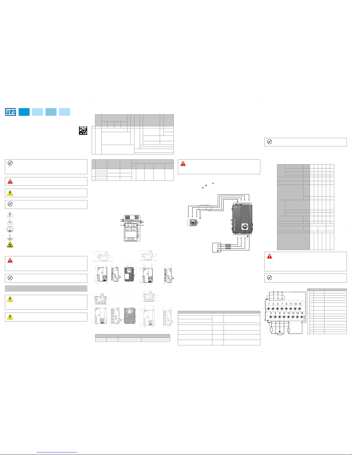
10.1 POWER CONNECTIONS
Descriptio n of the power terminal s:
Terminal X1 (L1/L, L2 /N and L3 (R, S , T, )): AC powe r supply.
Terminal X2 ( U/T1, V/T2, W/T3 , ): connection for the motor.
Terminal X3 (D C-, BR, DC+, ): DC bus and brake connection. DC- is the negative pole of the voltage
of the DC bus, BR is the c onnection of the b rake resistor and D C+ is the positive po le of the voltage of the
DC bus.
Shield
WEG industrial motor
U/T1
U/T1
V/T2
V/T2
W/T3
W/T3
R/L1 S/L2 T/L3
R/L1
S/L2
T/L3
Fuses
Input power supply
Figure 3: Power and grounding connection
10.2 INSTALLATIONS ACCORDING TO EUROPEAN DIRECTIVE OF ELECTROMAGNETIC
COMPATIBILITY
Inverters wi th option C2 or C3 (MW 500...C2...) feature internal RFI fi lter in order to red uce the
electromagnetic interference. Those inverters, when properly installed, meet the requirements of the
directive of electromagnetic compatibility.
These inverters were developed for professional applications only. Therefore, the emission limits of
harmonic cur rents by the standa rds EN 61000-3-2 and EN 61000 -3-2/A 14.
10.2 .1 Conformal Installation
1. Inverter with opt ional internal RFI fil ter MW500...C2... (with grounding switch of t he capacitors of the
internal RFI f ilter in the positio n ON).
2. Shielde d output cables (mo tor cables) with the s hield connected a t both ends, motor and inv erters, by
means of low impedance for high frequency connection. Maximum motor cable length and conducted
and radiated em ission levels acc ording to Table 5. If a lower cond ucted emission lev el and/or a longer
motor cable is de sired, then an ex ternal RFI f ilter must be us ed at the inver ter input. For mor e informatio n
(RFI filter commercial reference, motor cable length and emission levels) refer to the Table 5.
3. Shielded control cables, keeping the separations distance from other cables according to Table 3.2 the
user's manual.
4. Gro unding of the inv erter acco rding to instru ctions of Item 3. 2.4 Grounding Co nnections t he user's manua l.
5. Grounde d power supply.
10.2.2 Emission and Immunity Levels
Table 3: Emission and immunity levels
EMC Phenomenon Basic Standard Level
Emission:
Mains terminal d isturbance volt age Frequency
range: 150 kHz to 30 MHz)
IEC/EN 61800-3 It depe nds on the inverter m odel on the length o f the
cabo motor cable. R efer to Table 5
Electromagnetic radiation disturbance Frequency
Range: 30 MHz to 1000 MHz)
Immunity:
Fast transient-Burst IEC 61000-4-4 2 kV / 5 kHz (coup ling capacitor) in put cables
1 kV / 5 kHz control cabl es and remote HMI cab les
2 kV / 5 kHz (coupling ca pacitor) motor cabl es
Conducted Radio-Frequency Common Mode IEC 61000-4-6 0.15 to 80 MHz; 10 V; 80 % AM (1 kHz)
Motor, control and remote HMI cables
Surges
IEC 61000-4-5
1.2/50 μs, 8/20 μs
1 kV line-to-line coupling
2 kV line-to-ground coupling
Radio-Frequency Electromagnetic
Field IEC 61000-4-3
80 to 1000 MHz
10 V/m
80 % AM (1 kHz)
Definiti on of Standar d IEC/EM 61800 -3: "Adjusta ble Speed El ectrical Powe r Drives Syst ems"
Environments:
First Environment: environments that include domestic installations, as well as establishments directly
connected without intermediate transformer to a low-voltage power supply network which supplies
buildings used for domestic purposes.
Second Environment: includes all establishments other than those directly connected to a low-voltage
power supply network that supplies buildings used for domestic purposes.
Categories:
Category C1: inverters with a rate d voltage below 1000 V a nd intended for use in t he First Environm ent.
Category C2: inverters wit h a rated voltage below 100 0 V intended for use in th e First Environmen t, not
provided with a plug connector or movable installations. They must be installed and commissioned by a
professional.
NOTE!
A professional is a person or organization familiar with the installation and/or commissioning
of inverters, i ncluding their EM C aspects.
Categor y C3: inverte rs with a rated vo ltage below 100 0 V and intended f or use in the Sec ond Environm ent
only (not desig ned for use in the Firs t Environment.
The MW500 is sui table for application in a c ircuit able to supply not mo re than 30.000 symetric Ar ms
maximum of 20 0 V / 480 V, when protected by fus es classified as i ndicated below:
Table 4: List of mode ls of MW500 series, m ain electrica l specificatio ns
Inverter
Number of Input Phases
Power Supply R ated Voltage
Frame Size
Corrente Nominal de Saída
Maximum Motor
Recommended Fuse
Circuit Breaker
Power Wire Siz e
Grounding Wire Size
Dynamic
Braking
I²t [A²s]
UL [A]
Recommended WEG aR Fuse
Maximum Current
Recommend Resistor
Braking rms Current
Power Wire Siz e for DC
and BR Terminals
[Vrms]
[Arms]
[HP/kW ]
[A]
WEG
mm²
(AWG)
mm²
(AWG)
[A]
[Ω]
[A]
mm²
(AWG)
MW500A04P3S2DB66
1
200...
240
A
4,3 1/0.75 373 25 FNH00-25K-A 13,5 MPW18-3-U016
1.5
(16)
2.5
(14)
6 127 4.5
2.5
(14)
MW500A06P0S2DB66 6,0 1.5/ 1.1 420 20 FNH00-20K-A 25 MPW40-3-U025
2.5
(14)
2.5
(14)
8 100 5.7
2.5
(14)
MW500A02P6T4DB66
3
380...
480
2,6 1. 5/1.1 450 20 FNH00-20K-A 4,0 MPW18-3-U004
1.5
(16)
2.5
(14)
6 127 4.5
2.5
(14)
MW500A04P3T4DB66 4,3 2/1.5 450 20 FNH00-20K-A 6,3 MPW18-3-D063
1.5
(16)
2.5
(14)
6 127 4.5
2.5
(14)
MW500B 06P5T4DB 66...
3
380...
480
B
6,5 3 /2.2 450 - - 10 MPW25-10
1.5
(16)
2.5
(14)
8 100 5.7
2.5
(14)
MW500B10 P0T4DB66... 10 5/3.7 1000 - - 16 MPW25-16
2.5
(14)
2.5
(14)
16 47 11,5
2.5
(14)
DANGER!
The inverter m ust be connected to a p rotection groundi ng (PE).
Use grounding w iring with a gauge a t least equal to that i ndicated in Table 4.
The maximu m tightening torque of t he grounding conn ections is of 1.7 N.m (15 lbf.in).
Connect the gr ounding poi nts of the inver ter to a specifi c grounding ro d, or specif ic grounding
point or to the gen eral grounding po int (resistance ≤ 10 Ω).
Do not share the gr ounding wir ing with other e quipment tha t operate with hi gh currents (e.g.
high power motor s, soldering mach ines, etc.).
NOTE!
The wire gauge s listed in Table 4 are g uiding valu es. Installa tion conditi ons and the ma ximum
permitted voltage drop must be considered for the proper wiring sizing.
10.3 CONTROL CONNECTIONS
Connector Description
(**)
Upper terminal
1 DI1 Digital input 1
3 DI2 Digit al input 2
(*)
5 DI3 Digital input 3
7 D4 Digital input 4
9 + 24 V Power supply + 24 Vdc
11 DO1-RL-NO
Digital output 1
(Relay NO contact 1)
13 DO1-RL-C
Digital output 1
(Relay common point 1)
15 DO1-RL-NC
Digital output 1
(Relay NC contact 1)
Lower terminal
2 AO1 Analog out put 1
4 GND Reference 0 V
6 AI1 Analog input 1
8 + 10 V
Reference + 10 Vdc for
potentiometer
10 D O2-TR Digital output 2 (trans istor)
12 RS485 - A RS-485 (terminal A)
14 RS485 - B RS-485 (terminal B)
16 GND Reference 0 V
(*) Digital input 2 (DI2) can also be used as input in freq uency (FI).
For further deta ils refer to the progra mming manual of the M W500.
(**) For further information, refer to the detailed specification in Table 6.
AI1
AO1
GND
+10 V
DO2-T R
GND
+24 V
DO1-RL-NO
DO1-RL-C
DO1-RL-NC
DI1
DI2
DI3
DI4
≥5 kΩ
rpm
>300 Ω
RS-485 - A
RS-485 - B
Figure 4: Signals of the connector of t he CFW500-IOS plu g-in module
English
13309800
Page 2
For the corr ect connec tion of the con trol, use:
1. Gauge of the c ables: 0.5 mm² (20 AWG) to 1.5 mm² (14 AWG).
2. Maximu m torque: 0.5 N.m (4.50 lbf.in).
3. Wiring of the plu g-in module connec tor with shielded cab les separated from the ot her wiring (power,
command in 110 V / 220 Vac, etc.).
10.3 .1 RFI Filter
Built-in RFI filte r option is available to reduc e the conducted disturba nce from the inverter to the ma in
power supply in t he high frequency band (>150 kHz). It is neces sary to meet the maximum le vels of
conducted and radiated emissions of electromagnetic compatibility standards, such as EN 61800-3 and
EN 55011. For further detail s, refer to item 10.2 INSTALL ATIONS ACCORDING TO E UROPEAN DIR ECTIVE
OF ELECTROMAGNETIC COMPATIBILITY.
ATTENTION!
When inverte rs with intern al RFI filter is u sed in IT netwo rks (neutral c onductor not gr ounded
or grounded th rough a high ohm ic value resis tor), remove groun ding screw XE1, since th ose
kinds of netwo rk cause damage to th e filter capacitor s of the inverter.
Table 5: Conducte d and radiated emis sion levels, and add itional informa tion
Inverter Model
Without Ex ternal RFI Fi lter for
Decentralized Installation
With Exter nal RFI Filte r
Conducted Emission
- Maximum Motor
Cable Length
Radiated
Emission
External RFI
Filter Part
Number
(manufacturer:
XXX)
Conducted Emission -
Maximum
Motor Cable Le ngth
Radiated
Emission
- Category
Category C3Category
C2
Category
Category C2Category
C1
Without
Metallic
Cabinet
1 MW5 00A04P3 S2...C2... 10 m 5 m 30 m C2 - - - 2 MW5 00A06P 0S2...C2... 10 m 5 m 30 m C2 - - - 3 M W500A02 P6T4...C2... 10 m 5 m 30 m C3 - - - 4 M W500A04 P3T4...C2... 10 m 5 m 30 m C3 - - - 5 MW 500B06 P5T4...C2... 6 m - 6 m C3 - - - 6 M W500B10P 0T4...C2... 6 m - 6 m C3 - - - -
10.4 ACCESSORIES
The accesso ries are hardware r esources that ca n be added in the appli cation with the MW50 0.
The accesso ries are incorpor ated to the inverters in a n easy and quick way by us ing the "Plug and Play"
concept. Whe n an accessory is conn ected to the inverter, the cont rol circuitry identi fies the model and
informs the cod e of the accessory con nected in parameter P00 27. The accessor y must be installed or
modified with t he inverter de -energized. T hey may be ordere d separately a nd are sent in thei r own
package containing the components and manuals with detailed instructions for their installation, operation
and setting.
11 USE OF THE H MIR TO OPERATE THE INVE RTER
Press this key to accele rate the motor up to the spe ed set in P0122 within the tim e determined by the
acceleration ra mp. The motor speed is ke pt while the key is pres sed. When the key is rel eased, the
motor decelerates within the time determined by the deceleration ramp, until it stops.
This function is ac tive when all the con ditions below are m et:
1. Turn/Stop = Stop.
2. Enable General = Ac tive.
3. P0225 = 1 in LOC and/or P0228 = 1 in REM.
Press this key to commute b etween LOCAL
and REMOTE mode.
Active when:
P0220 = 2 or 3
Press this key to define t he motor rotation
direction.
Active when:
P0223 = 2 or 3 in LOC and/or
P0226 = 2 or 3 in REM
- When in the monitori ng mode: press this
key to increase the spe ed.
- When in the setting mo de, level 1: press this
key to go to the previous grou p.
- When in the setting m ode, level 2: press
this key to go to the next para meter.
- When in the setting m ode, level 3: press
this key to increase the c ontent of the
parameter.
- When in the setting m ode, level 1: press
this key to return to the moni toring mode.
- When in the setting m ode, level 2:
press this key to return to leve l 1 of the
setting mode.
- When in the setting m ode, level 3: press
this key to cancel the new v alue (new value
is not saved) and retur n to level 2 of the
setting mode.
When in the monitori ng mode: press this key to en ter
the setting mode.
- When in the setting m ode, level 1: press this key
to select the desire d parameter group - it sho ws the
parameter group selected.
- When in the setting m ode, level 2: press this key
to show the parameter - it s hows the content of the
parameter in order to c hange the content.
- When in the setting m ode, level 3: press this key to
save the new content of the p arameter - it returns to
level 2 of the setting mo de.
When in the monitor ing mode: press this key to
decrease the speed.
- When in the setting m ode, level 1: press this key to
go to the next group.
- When in the setting m ode, level 2: press this key to
go to the previous para meter.
- When in the setting m ode, level 3: press this key to
decrease the conte nt of the parameter
Press this key to accele rate the motor within th e time
determined by the acceleration ramp.
Active when:
P0224 = 0 in LOC or P0227 = 0 in REM
Press this key to decel erate the motor within t he time
determined by the deceleration ramp.
Active when:
P0224 = 0 in LOC or P0227 = 0 in REM
11.1 INDICATIONS OF DISPLAY
Main display
Menu (to select the
parameter group s) only one parameter
group is shown at
a time
Measurement unit
(it refers to the valu e
of the main indicat ion)
Secondary indication
Bar graph
Inverter status
11.2 OPERATING MODES OF THE HMI
Monitoring Mode
It is the initial sta tus of the HMIR after the poweri ng up and of the initializati on
screen, with default values
The field Menu is n ot active in this mode
The main display, sec ondary display and ba r graph indicate the value s of three
parameters prede fined by P0205, P0206 a nd P0207
From the monitorin g mode, when you p ress the key ENTER/MENU, you commu te
to the setting mode
Monitoring
Setting
level 2
Setting
level 3
Setting
level 1
Enter
Menu
Enter
Menu
Enter
Menu
Back
Esc
Back
Esc
Back
Esc
Setting Mode
Level 1:
This is the first le vel of the setting mode. It is p ossible to choose the par ameter
group using the keys and
The main display, secondary display, bar graph and measurement units are not
shown in this level
Press the key ENTER/MENU to go to level 2 of the s etting mode - p arameter se lection
Press the key BACK/ ESC to return to the moni toring mode.
Level 2:
O número do parâme tro é exibido no display princi pal e o seu conteúdo no
display secundário
Use the keys and to find the desired parame ter
Press the key ENTER/MENU to go to level 3 of the se tting mode - modifi cation
of the parameter conte nt
Press the key BACK/ ESC to return to level 1 of th e setting mode.
Level 3:
The content of the pa rameter is shown on th e main display an d the number of the
parameter is shown on the secondary display
Use the keys and to configure the new value for the selected parameter
Press the key ENTER/MENU to confirm th e modification (sa ve the new value) or
BACK/ESC to cance l the modific ation (not save the ne w value). In both case s, the
HMIR returns to level 2 of th e setting mode
12 START-UP PREPARATION
DANGER!
Always disconnect the main power supply before making any connection.
1. Check if the power, grounding and control connections are correct and firm.
2. Remove all m aterials left fro m the inside of the inve rter.
3. Check if the motor connections and motor current and voltage match the inverter.
4. Mechanically u ncouple the motor from the lo ad. If the motor cannot be uncoup led, be sure that its
turning in any di rection (clockw ise or counterclo ckwise) will not ca use damages to the mac hine or risk
of accidents.
5. Close the co vers of the inverter.
6. Measure th e power supply and ve rify if it is withi n the allowed range.
7. Apply powe r to the input: close the i nput disconnec ting switch.
8. Check the re sult of the first tim e power-up:
The HMI display indicates:
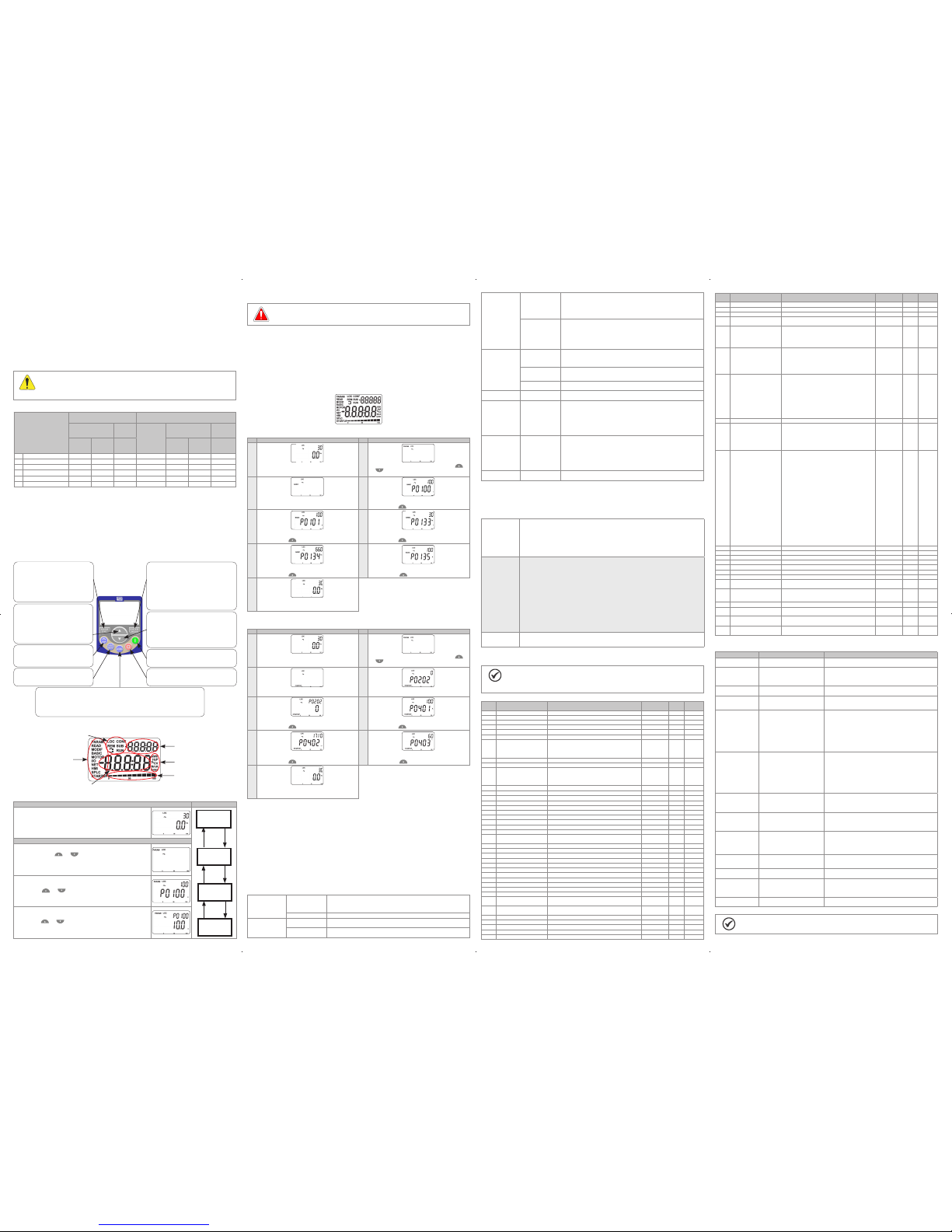
12.1 BASIC APPLICATION
Seq Display Indication/Action Seq Display Indication/Action
1
2
Monitoring mode
Press the key ENTER/MENU to enter the 1
st
level of
the programming mode
The PARAM group is selected, p ress the keys or
until selecting the BASIC group
3 4
When the BASIC group is s elected press the key
ENTER/MENU
Basic Applic ation routine is st arted. If necess ary, modify
the content of "P0100 - Acce leration Time"
Press the key for the next parameter
5 6
If necessar y, modify the content of "P0101 -
Deceleration Time"
Press the key for the next parameter
If necessar y, modify the content of "P0133 - Minim um
Speed"
Press the key for the next parameter
7 8
If necessar y, modify the conten t of "P0134 - Maximum
Speed"
Press the key for the next parameter
If necessar y, modify the conte nt of "P0135 - Maximum
Output Current"
Press the key for the next parameter
9
To end the Start-up rout ine, press the key BAC K/ESC
To return to the monitorin g mode, press the key
BACK/ ESC again
12.2 V/F CON TROL TYPE (P0 202 = 0)
Seq Display Indication/Action Seq Display Indication/Action
1
2
Monitoring mode
Press the key ENTER/MENU to enter 1
st
level of
programming mode
The PARAM group is selected, p ress the keys or
until selecting the STARTUP group
3 4
When the STARTUP group is sele cted press the key
ENTER/MENU
If necessar y, press ENTER/MENU to modify the
content of "P0202 - Cont rol Type" for P0202 = 0 (V/f)
5 6
When the desire d value is reached, press ENTER/
MENU to save the modification
Press the key for the next parameter
If necessar y, modify the content of "P0401 - Motor
Rated Current”
Press the key for the next parameter
7 8
If necessar y, modify the content of "P0402 - Moto r
Rated Speed"
Press the key for the next parameter
If necessar y, modify the content of "P0403 - Moto r
Rated Frequency
Press the key for the next parameter
9
To end the Start-up rout ine, press the Key B ACK/ESC
To return to the monitorin g mode, press the key
BACK/ESC again
13 TECHNICAL SPECIFICATIONS
POWER DATA
Power Supply:
Tolerance: -15 % to +10 %.
Frequency: 50 /60 Hz (48 Hz to 62 Hz).
Phase imbal ance: ≤ 3 % of the rated phas e-to-phase input vo ltage.
Overvolt age according to Cate gory III (EM 61010/UL 508C).
Transient voltage according to Category III.
Maximum of 10 co nnections per ho ur (1 every 6 minutes).
Typical effi ciency: ≥ 97 %.
14 ELECTRONICS/GENERAL DATA
Table 6: Electronics/general data
Control Method Types o f control:
- V/f (Scalar))
- VVW: voltage vector control.
PWM SVM (Space Vector Modulation)
Output frequency 0 to 500 Hz, resol ution of 0.015 Hz
Performance V/f control S peed regulatio n: 1 % of the rated speed (wit h slip compensat ion)
Speed variati on range: 1:20
Vector control (VVW) Speed regulatio n: 1 % of the rated speedl
Speed variati on range: 1:30
Inputs
(*)
Analog Knob addit ional input for sp eed reference var iation
1 insulated inpu t. Levels: (0 to 10) V or (0 to 20) mA or (4 to 20) mA
Linearity e rror ≤ 0.25 %
Impedance: 100 kΩ fo r voltage input, 50 0 Ω for current input
Programmable functions
Maximum volt age permitted in t he input: 30 Vdc
Digital 4 insulated inputs
Programmable functions:
- active high (PNP): ma ximum low level of 15 Vdc / mi nimum high leve l of 20 Vdc
- active low (NPN): max imum low level of 5 Vdc / mini mum high level of 9 Vdc
Maximum input voltage of 30 Vdc
Input current: 4.5 mA
Maximum input current: 5.5 mA
Outputs
(*)
Relay 1 relay with NC/NO contact
Maximum voltage: 240 Vac
Maximum current: 0.5 A
Programmable functions
Transistor 1 insulated digital output open sink (uses as reference the 24 Vdc power supply)
Maximum current 150 mA
(**)
(maximum capacity of the 24 Vdc) power supply
Programmable functions
Power supply 24 Vdc power supply. Maximum capacity: 150 mA
10 Vdc power supply. Maximum capacity: 2 mA
Communication Interface RS-485 Insulated RS-485
Modbus-RTU protocol with maximum communication of 38.4 kbps
Safety Protection Overcurrent/phase-phase short circuit in the output
Overcurrent/phase-ground short circuit in the output
Under/overvoltage
Overtemperature in the heatsink
Overload in the motor
Overload in the power module (IGBTs)
External alarm/fault
Setting error
Human-machine
interface (keypad)
Remote keypad
(HMIR)
9 keys: Start/Sto p, up arrow, down arrow, Direction of Rotati on, Jog, Local/
Remote,
BACK/ESC and ENT ER/MENU
LCD display
View/edition of all parameters
Indication accuracy:
- current: 5 % of the rated cu rrent
- speed resoluti on: 0.1 Hz
Enclosure Degree of protection IP66
UL type 4X
(*) The numbe r and/or type of analog/digita l inputs/outputs may vary, depend ing on the Plug-in module (acce ssory) used. For the table abov e, it was
considered the standard plug-in module. For further information, refer to the programming manual and the guide supplied with the optional item.
(**) The maxim um capacity of 150 mA must be consi dered by adding the load of the 24 V power s upply and transistor outpu t, that is, the sum of the
consumption of both mus t not exceed 150 mA.
15 CONSIDERED STANDARDS
Table 7: Considered standards
Safety
standards
EN 61800-5-1 - safety ele ctrical, therma l and energy requi rements
EN 50178 - electronic equi pment for use in power i nstallations
EN 60204-1 - safety of mach inery. Electric al equipment of mac hines. Part 1: gener alrequirement s
Note: For the machine to comply with this standard, the manufacturer of the machine is responsible
for installing an e mergency stop dev ice and equipme nt to disconnect the i nput power suppl y
EN 60146 (IEC 146) - semiconduc tor converters
EN 61800-2 - adjustabl e speed elect rical power dri ve systems - part 2: g eneral requi rements - rating
specifications for low voltage adjustable frequency AC power drive systems
Electromagnetic
compatibility (EMC)
standards
EN 61800-3 - adjusta ble speed electrical pow er drive systems - part 3: EMC prod uct standard
including specific test methods
EN 55011 - limits and methods o f measurement of radio di sturbance character istics of industrial,
scientific and medical (ISM) radio-frequency equipment
CISPR 11 - industrial, sci entific and medical (ISM ) radio-frequency equip ment - electromagnetic
disturbance ch aracteristics - l imits and methods of m easurement
EN 61000-4-2 - electromagnetic compatibility (EMC) - part 4: testing and measurement techniques
- section 2: electrostatic discharge immunity test
EN 61000-4-3 - electromagnetic compatibility (EMC) - part 4: testing and measurement techniques
- section 3: radiated, radio-frequency, electromagnetic field immunity test
EN 61000-4-4 - electromagnetic compatibility (EMC) - part 4: testing and measurement techniques
- section 4: electrical fast transient/burst immunity test
EN 61000-4-5 - electromagnetic compatibility (EMC) - part 4: testing and measurement techniques
- section 5: surge immunity test
EN 61000-4-6 - electromagnetic compatibility (EMC) - part 4: testing and measurement techniques
- section 6: immuni ty to conducted dis turbances, indu ced by radio-freq uency fields
Mechanical
construction
standards
EN 60529 - degrees o f protection provid ed by enclosures (I P code)
UL 50 - enclosure s for electrical e quipment
16 MAIN PAREMETERS
NOTE!
ro = read only para meter.
V/f = parameter avai lable in V/f mode.
cfg = configur ation parameter, value c an only be change d with the motor stoppe d.
Param. Description Adjustable Range
Factory
Setting
Propr. Groups
P0000 Access to Parameters 0 to 9999 0
P0001 Speed Reference 0 to 65535 ro READ
P0002 Motor Speed 0 to 65535 ro READ
P0003 Motor Current 0.0 to 200.0 A ro READ
P0004 DC Link Vol tage (Ud) 0 to 2000 V ro READ
P0005 Motor Frequency 0.0 to 500.0 Hz ro READ
P0006 Inverter Status 0 = Ready
1 = Run
2 = Undervoltage
3 = Fault
4 = Self-Tuning
5 = Configuration
6 = DC-Braking
7 = Sleep Mode
ro READ
P0007 Motor Voltage 0 to 2000 V ro READ
P0011 Power Factor -1.00 to 1.00 A ro READ
P0012 DI8 to DI1 Status Bit 0 = DI1
Bit 1 = DI2
Bit 2 = DI3
Bit 3 = DI4
Bit 4 = DI5
Bit 5 = DI6
Bit 6 = DI7
Bit 7 = DI8
ro READ, I/O
P0022 FI Hz Val ue 1 to 20000 Hz ro R EAD, I/O
P0023 Mai n SW Version 0.00 to 6 55.35 ro READ
P0030 Heatsink Temperature -20 to 150 ºC ro READ
P0037 Motor Overload Ixt 0 to 100 % ro READ
P0047 CONFIG Status 0 to 999 ro READ
P0048 Present Ala rm 0 to 999 ro READ
P0049 Present Fault 0 to 999 ro READ
P0050 La st Fault 0 to 999 ro READ
P0100 Acceleration Time 0.1 to 999.0 s 10,0 s BASIC
P0101 Deceleration Time 0.1 to 999.0 s 10,0 s BASIC
P0120 Speed Ref. Ba ckup 0 = Inactive
1 = Active
3 = Backup by P0121 1
P0121 S peed Reference v ia HMI 0.0 to 500.0 Hz 3.0 Hz
P0124 Multispe ed Ref. 1 -500.0 to 500.0 Hz 3.0 Hz
P0125 Multispe ed Ref. 2 -500.0 to 500.0 Hz 10.0 (5.0) Hz
P0126 Multisp eed Ref. 3 -500.0 to 500.0 Hz 20.0 (10.0) Hz
P0127 Multispe ed Ref. 4 -500.0 to 500.0 Hz 30.0 (20.0) Hz
P0128 Multisp eed Ref. 5 -500.0 to 500.0 Hz 40.0 (30.0) Hz
P0129 Multisp eed Ref. 6 -500.0 to 500.0 Hz 50.0 (40.0) Hz
P0130 Multispe ed Ref. 7 - 500.0 to 500.0 Hz 60.0 (50.0) Hz
P0131 Multispee d Ref. 8 - 500.0 to 500.0 Hz 66.0 (55.0) Hz
P0133 Minimum Speed 0.0 to 500.0 Hz 3.0 Hz BASIC
P0134 Maximu m Speed 0.0 to 500.0 Hz 66.0 (55.0) Hz BASIC
P0135 Max. Output Current 0.0 to 200.0 A 1.5 x I
nom
BASIC,
MOTOR
P0136 Manual Torque Boost 0.0 to 30.0 % According to
inverter model
V/f BASIC,
MOTOR
P0137 Autom. Torque Boost 0.0 to 30.0 % 0.0 % V/f MOTO R
P0138 Slip Compensation -10.0 to 10.0 % 0.0 % V/f MOTOR
P0139 Output Current Filter 0 to 9999 ms 50 ms
P0142 Max. Output Voltage 0.0 to 100.0 % 100.0 % cfg, V/f
P0143 Interm. Output Voltage 0.0 to 100.0 % 66.7 % cfg, V/f
Param. Description Adjustable Range
Factory
Setting
Propr. Groups
P0145 Field Weakening Frequency 0.0 to 50 0.0 Hz 60.0 (50.0) Hz cfg, V/f
P0146 Interm ediate Frequency 0.0 to 500.0 Hz 40.0 (33.3) Hz cf g, V/f
P0156 Overl. Cur r. 100 % Speed 0.0 to 200.00 A 1.1 x Inom MOTOR
P0202 Control Type 0 = V/f
1 a 4 = Not Used
5 = VVW 0 cfg STA RTUP
P0204 Load/Save Parameters 0 and 1 = Not Used
2 = Reset P0045
3 and 4 = Not Used
5 = Load WEG 60 Hz
6 = Load WEG 50 Hz
7 = Load User 1
8 = Load User 2
9 = Save User 1
10 = Save User 2
0 cfg
P0220 LOC/REM Selection Source 0 = Always LO C.
1 = Always REM.
2 = HMI Key (LOC)
3 = HMI Key (REM)
4 = DIx
5 = Serial/USB (LOC)
6 = Serial/USB (REM )
7 and 8 = Not Used
9 = CO/DN/DP (LOC)
10 = CO/DN/DP (REM)
11 = SoftPLC
4 cfg I/O
P0221 LOC Reference Sel. 0 = Keypad
1 = AI1
2 = AI2
3 = AI3
4 = FI
5 = AI1 + AI2 > 0
6 = AI1 + AI2
7 = E.P.
8 = Multispeed
9 = Serial/USB
10 = Not Used
11 = CO/DN/DP
12 = SoftPLC
13 = Not Used
14 = AI1 > 0
15 = AI2 > 0
16 = AI3 > 0
17 = FI > 0
18 = Knob
18 cfg I/O
P0222 REM R eference Sel. See options in P0221 9 cfg I/O
P0223 LOC FWD/REV Selection 0 = Always F WD
1 = Always REV
2 = HMI Key (FWD)
3 = HMI Key (REV)
4 = DIx
5 = Serial/USB (F WD)
6 = Se rial/ USB (REV )
7 and 8 = Not Used
9 = CO/DN/DP (H)
10 = CO/DN/DP (AH)
11 = Not Used
12 = SoftPLC
4 cfg I/O
P0263 DI1 Function 0 = Not Used
1 = Run/Stop
2 = General Enable
3 = Quick Stop
4 = FWD Run
5 = REV Run
6 = Start
7 = Stop
8 = Clockwise Rotat ion Dir
9 = LOC/REM
10 = JOG
11 = Increase E.P.
12 = Decrease E.P.
13 = Multispeed
14 = 2nd Ramp
15 to 17 = Not Used
18 = Sem Alarme Ext.
19 = Sem Falha Ext.
20 = Reset
21 = SoftPLC
22 = Manual/Auto PID
23 = Not Used
24 = Disable Flying Sta rt
25 = Not Used
26 = Program. Off
27 = Load User 1
28 = Load User 2
29 = PTC
30 and 31 = Not Used
32 = 2nd Ramp Multispeed
33 = 2nd Ramp E.P. Ac.
34 = 2nd Ramp E.P. De.
35 = 2nd Ramp FWD Run
36 = 2nd Ramp REV Run
37 = Start / Inc. E.P.
38 = Dec. E.P. / Stop
39 = Function 1 Application
40 = Function 2 Application
41 = Function 3 Application
42 = Function 4 Application
43 = Function 5 Application
44 = Function 6 Application
45 = Function 7 Application
46 = Function 8 Application
1 cfg I/O
P0264 DI2 Function See options in P0263 8 cfg I/O
P0265 DI3 Function See options in P0263 20 cfg I/O
P0266 DI4 Function See options in P0263 9 cfg I/O
P0267 DI5 Function See options in P0263 0 cfg I/O
P0268 DI6 Function See options in P0263 0 cfg I/O
P0269 DI7 Function See options in P0263 0 cfg I/O
P0270 DI8 Function See options in P0263 0 cfg I/O
P0295 VFD R ated Curr. 0.0 to 200.0 A According to
inverter model
ro READ
P0296 Power Supply Rated Voltage 0 = 200 / 240 V
1 = 380 / 480 V
2 = 500 / 600 V
According to
inverter model
ro, cfg READ
P0297 Switching Frequency 1500 to 15000 kH z 4000 kHz
P0401 Motor Rate d Current 0.0 to 200.0 A 1.0 x I
nom
cfg MOTOR,
STARTU P
P0402 Motor R ated Speed 0 to 30000 rpm 1710 (1425) rpm cfg MOTOR,
STARTU P
P0403 Motor Ra ted Frequency 0 to 500 Hz 60 (50) Hz cfg MOTOR,
STARTU P
17 FAULTS AND ALARMS
Falha / Alarme Descrição Causas Prováveis
A0046
Motor Overload
Motor overload alarm Overload on the m otor shaft
A0050
Power Module
Overtemperature
Overtemperature alarm from the
power module temperature sensor
(NTC)
High ambient te mperature ar ound the inver ter (>50 °C (> 122 °F))
and high output current
Blocked or defec tive fan
Heatsink is too dir ty, preventing the ai r flow
A0090
External Alarm
External ala rm via DIx (option "No
External Ala rm" in P026x)
Wiring on DI1 to DI8 inp uts are open or have po or contact
A0700
Communication Fault
with Remote HMI
No communication with remote HMI,
but there is no spee d command or
reference for this s ource
Check if the communication interface with the HMI is properly
configured in parameter P0312
HMI cable disconnected
F0021
Undervoltage on the
DC Link
Undervoltage fault on the
intermediate circuit
Wrong voltage supply; check if the data on the inverter label
complies with the power supply and parameter P0296
Supply voltage to o low, producing vo ltage on the DC li nk below
the minimum value ( in P0004):
Ud < 200 Vdc in 200 / 240 Vac (P0296 = 0)
Ud < 360 Vdc in 380 / 480 Vac (P029 6 = 1)
Ud < 500 Vdc in 500 / 600 Vac (P0 296 = 2)
Phase fault in the i nput
Fault in the pre-c harge circuit
F0022
Overvoltage on the DC
Link
Overvoltage fault on the intermediate
circuit
Wrong voltage supply; check if the data on the inverter label
complies with the power supply and parameter P0296
Supply voltage i s too high, producing volta ge on the DC link
above the maximu m value (in P0004):
Ud > 410 Vdc in 200 / 240 Vac (P0296 = 0)
Ud > 810 Vdc in 380 / 480 Vac (P0296 = 1)
Ud > 1000 Vdc in 500 / 600 Vac (P02 96 = 2)
Load inertia is to o high or deceler ation ramp is too fast
P0151 or P0153 setting is too high
F0031
Communication Fault
with Plug-in Module
Main control cann ot set a
communication link with the plug-in
module
Plug-in module is damaged
Plug-in module is not properly connected
Problem in the ide ntificati on of the plug-i n module; refe r to P0027
for further information
F0051
IGBTs Overtemperature
Overtemperature fault measured
on the temperature s ensor of the
power pack
High ambient te mperature arou nd the inverte r (>50 °C (>122 °F))
and high output current
Blocked or defec tive fan
Heatsink is too dir ty, preventing the ai r flow
F0070
Overcurrent/Short
Circuit
Overcurrent or short circuit on the
output, DC link or bra king resistor
Short circuit between two motor phases
Short circuit of the rheostatic braking resistor connecting cables
IGBTs module in short circuit or damaged
Start with too sh ort accelerat ion ramp
Start with motor spinning without the Flying Start function
F0072
Motor Overload
Motor Overload Faul t (60 s in
1.5xInom)
P0156, P0157 and P0158 setting is too low in re lation to the
motor operating current
Overload on the m otor shaft
F0080
CPU Fault (Watchdog)
Fault related to the supervision
algorithm
Electric noise
Inverter firmware fault
F0084
Auto-diagnosis Fault
Fault related to the auto matic
identification a lgorithm of the inve rter
hardware and plug-in module
Poor contact in the connection between the main control and
the power pack
Hardware not compatible with the firmware version
Defect on the inter nal circuits of the i nverter
F0091
External Fault
External faul t via DIx (“No Exte rnal
Fault” in P026x)
Wiring on DI1 to DI8 inp uts are open or have po or contact
NOTE!
For further information, refer www.weg.net.
Document: 10003693218 / 00
 Loading...