


Operator's ual
26" RiDiNG MOWER
SiDE DISCHARGE
ELECTRIC START
Catalog No.
28600
436518 Rev. 3
iMPORTANT:
Read and follow all Safety
Rules and Instructions before
operating this equipment.
Patents Pending

Warranty ................................................. 2
Safety Rules ........................................... 3
Product Specifications ............................ 6
Assembly/Pre-Operation ........................ 7
Operation .............................................. 10
Maintenance ......................................... 16
Service and Adjustments ...................... 20
Storage ................................................. 24
Troubleshooting .................................... 25
Repair Parts .......................................... 27
Maintenance Schedule ......................... 16
LIMITED WARRANTY
The Manufacturer warrants to the original consumer purchaser that this product as manufactured is free from defects in materi-
als and workmanship. For a period of two (2) years from date of purchase by the original consumer purchaser, we wiii repair or
replace, at our option, without charge for parts or labor incurred in replacing parts, any part which we find to be defective due
to materials or workmanship. This Warranty is subject to the following limitations and exclusions.
1. This warranty does not apply to the engine, battery (except as noted below) or components parts thereof. Please refer to
the applicable manufacturer's warranty on these items.
2. Transportation charges for the movement of any power equipment unit or attachment are the responsibility of the purchas-
er. Transportation charges for any parts submitted for replacement under this warranty must be paid by the purchaser
unless such return is requested by the manufacturer.
3. Battery Warranty: On products equipped with a Battery, we will replace, without charge to you, any battery which we find
to be defective in manufacture, during the first ninety (90) days of ownership. After ninety (90) days, we will exchange the
Battery, charging you 1/12 of the price of a new Battery for each furl month from the date of the original sale. Battery must
be maintained in accordance with the instructions furnished.
4. The Warranty does not apply to any products used for rental or commercial purposes.
5. This Warranty applies only to products which have been properly assembled, adjusted, operated, and maintained in ac-
cordance with the instructions furnished. This Warranty does not apply to any product which has been subjected to altera-
tion, misuse, abuse, improper assembly or installation, delivery damage, or to normal wear of the product.
6. Exclusions: Excluded from this Warranty are belts, blades, blade adapters, normal wear, normal adjustments, standard
hardware and normal maintenance.
7. In the event you have a claim under this Warranty, you must return the product to an authorized service dealer.
Should you have any unanswered questions concerning this Warranty, please contact:
HOP
Outdoor Products Customer Service Dept.
9335 Harris Corners Parkway
Charlotte, NC 28269 USA
giving the model number, serial number and date of purchase of your product and the name and address of the authorized
dealer from whom it was purchased.
THIS WARRANTY DOES NOT APPLY TO INCIDENTAL OR CONSEQUENTIAL DAMAGES AND ANY iMPLIED WARRAN-
TIES ARE LIMITED TO THE SAME TIME PERIODS STATED HEREIN FOR OUR EXPRESSED WARRANTIES. Some areas
do not allow the limitation of consequential damages or limitations of how long an implied Warranty may last, so the above
limitations or exclusions may not apply to you. This Warranty gives you specific legal rights, and you may have other rights
which vary from locale to locale.
This is a limited Warranty within the meaning of that term as defined in the Magnuson-Moss Act of 1975.
In Canada contact:
HOP
5855 Terry Fox Way
Mississauga, Ontario
L5V 3E4
2
DANGER: This cutting machine is capable of amputating hands and feet and throwing
objects. Failure to observe the following safety instructions could result in serious
injury or death.
_,WARNING: In order to prevent acciden-
tal starting when setting up, transporting,
adjusting or making repairs, always discon-
nect spark plug wire and place wire where
it cannot contact spark plug.
,_I_WARNING: Do not coast down a hill in
neutral, you may lose control of the riding
mower.
_,WARNING: Engine exhaust, some of its
constituents, and certain vehicle components
contain or emit chemicals known tothe State
of California to cause cancer and birth defects
or other reproductive harm.
_WARNING:This unit is not intended for
towing, or use of wheel weights. Only use
attachments designed specifically for this
riding mower.
_WARNING: Battery posts, terminals and
related accessories contain lead and lead
compounds, chemicals known tothe State of
California to cause cancer and birth defects
or other reproductive harm. Wash hands
after handling.
I. GENERAL OPERATION
• Read, understand, and follow all instruc-
tions on the machine and in the manual
before starting.
• Do not put hands or feet near rotating
parts or under the machine. Keep clear
of the discharge opening at all times.
• Only allow responsible adults, who are
familiar with the instructions, to operate
the machine.
• Clear the area of objects such as rocks,
toys, wire, etc., which could be picked up
and thrown by the blade.
• Be sure the area is clear of bystanders
before operating. Stop machine ifanyone
enters the area.
• Never carry passengers.
• Do not mow in reverse unless absolutely
necessary. Always look down and behind
before and while backing.
• Never direct discharged material toward
anyone. Avoid discharging material
against a wall or obstruction. Material may
ricochet back toward the operator. Stop the
blade when crossing gravel surfaces.
• Do not operate machine withoutthe entire
grass catcher, discharge chute, or other
safety devices in place and working.
• Slow down before turning.
• Never leave a running machine unat-
tended. Always turn off blade, set park-
ing brake, stop engine, and remove keys
before dismounting.
• Disengage blade when not mowing. Shut
off engine and wait for all parts to come
to a complete stop before cleaning the
machine, removing the grass catcher, or
unclogging the discharge chute.
• Operate machine only in daylight or good
artificial light.
• Do not operate the machine while under
the influence of alcohol or drugs.
• Watch for traffic when operating near or
crossing roadways.
• Use extra care when loading or unloading
the machine into a trailer or truck.
• Always wear eye protection when operat-
ing machine.
• Data indicates that operators, age 60
years and above, are involved in a large
percentage of riding mower-related inju-
ries. These operators should evaluate
their ability to operate the riding mower
safely enough to protect themselves and
others from serious injury.
• Keep machine free of grass , leaves or
other debris build-up which can touch hot
exhaust / engine parts and burn. Do not
allow the mower deck to plow leaves or
other debris which can cause build-up to
occur. Clean any oil or fuel spillage before
operating or storing the machine. Allow
machine to cool before storage.
3

Ii. SLOPE OPERATION
Slopes are a major factor related to loss of
control and tip-over accidents, which can
result in severe injury or death. Operation
on all slopes requires extra caution. If you
cannot back up the slope or if you feel uneasy
on it, do not mow it.
• Mow up and down slopes (15 ° Max), not
across.
• Watch for holes, ruts, bumps, rocks, or
other hidden objects. Uneven terrain could
overturn the machine. Tall grass can hide
obstacles.
• Choose a low ground speed so that you
will not have to stop or shift while on the
slope.
• Do not mow on wet grass. Tires may lose
traction.
• Always keep the machine in gear when
going down slopes. Do not shift to neutral
and coast downhill.
• If machine stops while going uphill,
disengage blade, shift into reverse and
back down slowly.
• Avoid starting, stopping, or turning on a
slope. Ifthe tires lose traction, disengage
the blade and proceed slowly straight down
the slope.
• Keep all movement on the slopes slow and
gradual. Do not make sudden changes
in speed or direction, which could cause
the machine to roll over.
• Use extra care while operating machine
with grass catchers or other attachments;
they can affect the stability of the machine.
• Do no use on steep slopes.
• Do not try to stabilize the machine by
putting your foot on the ground.
• Do not mow near drop-offs, ditches, or
embankments. The machine could sud-
denly roll over if a wheel is over the edge
or if the edge caves in.
Iii. CHILDREN
Tragic accidents can occur if the operator
is not alert to the presence of children.
Children are often attracted to the machine
and the mowing activity. Never assume
that children will remain where you last
saw them.
• Keep children out ofthe mowing area and
in the watchful care of a responsible adult
other than the operator.
• Be alert and turn machine off if a child
enters the area.
• Before and while backing, look behind and
down for small children.
• Never carry children, even with the blade
shut off. They may fall off and be seriously
injured or interfere with safe machine
operation. Children who have been given
rides in the past may suddenly appear in
the mowing area for another ride and be run
over or backed over by the machine.
• Never allow children to operate the ma-
chine.
• Use extra care when approaching blind
corners, shrubs, trees, or other objects
that may block your view of a child.
IV. SERVICE
SAFE HANDLING OF GASOLINE
To avoid personal injury or property dam-
age, use extreme care in handling gasoline.
Gasoline is extremely flammable and the
vapors are explosive.
• Extinguish all cigarettes, cigars, pipes,
and other sources of ignition.
• Use only approved gasoline container.
• Never remove gas cap or add fuel with
the engine running. Allow engine to cool
before refueling.
• Never fue! the machine indoors.
• Never store the machine orfue! container
where there is an open flame, spark, or
pilot light such as on a water heater or
other appliances.
4

• Never fill containers inside a vehicle or
on a truck or trailer bed with plastic liner.
Always place containers on the ground
away from your vehicle when filling.
• Removegas-powered equipmentfromthe
truck or trailer and refuel it on the ground.
If this is not possible, then refuel such
equipment with a portable container, rather
than from a gasoline dispenser nozzle.
• Keep the nozzle in contact with the rim
of the fuel tank or container opening at
all times until fueling is complete. Do not
use a nozzle lock-open device.
• Iffue! is spilled on clothing, change clothing
immediately.
• Never overfill fuel tank. Replace gas cap
and tighten securely.
GENERALSERVICE
• Never operate machine in a closed area.
• Keep all nuts and bolts tight to be sure the
equipment is in safe working condition.
• Never tamper with safety devices. Check
their proper operation regularly.
• Keep machine free of grass, leaves, or
other debris build-up. Clean oil or fuel spill-
age and remove any fuel-soaked debris.
Allow machine to cool before storing.
• If you strike a foreign object, stop and
inspect the machine. Repair, if necessary,
before restarting.
• Never make any adjustments or repairs
with the engine running.
• Check grass catcher components and the
discharge chute frequently and replace
with manufacturer's recommended parts,
when necessary.
• Mower blade is sharp. Wrap the blade or
wear gloves, and use extra caution when
servicing them.
• Check brake operation frequently. Adjust
and service as required.
• Maintain or replace safety and instruction
labels, as necessary.
• Be sure the area is clear of bystanders
before operating. Stop machine if anyone
enters the area.
• Never carry passengers.
• Do not mow in reverse unless absolutely
necessary. Always look down and behind
before and while backing.
5

Gasoline Capacity 1.2 qt.
and Type: Unleaded Regular
Oil Type SAE 30 (above 32°F)
API-SG-SL): SAE 5W-30(below 32°F
Oil Capacity: 20 oz.
Spark Plug: Champion RC12YC
(Gap: .030")
Ground Speed Forward: 0-4 mph
Reverse: 0-1 mph
Blade Bolt Torque: 45-55 Ft. Lbs.
CUSTOMER RESPONSIBILITIES
• Read and observe the safety rules.
• Follow a regular schedule in maintaining,
caring for and using your riding mower.
• Follow the instructions under "Mainte-
nance" and "Storage" sections of this
owner's manual.
A_,WARN]NG" This riding mower is
equipped with an internal combustion en-
gine and should not be used on or near any
unimproved forest-covered, brush-covered
or grass-covered land unless the engine's
exhaust system is equipped with a spark
arrester meeting applicable local or state
laws (if any). If a spark arrester is used, it
should be maintained in effective working
order by the operator.
In the state of Californiathe above is required
by law (Section 4442 of the California Public
Resources Code). Other states may have
similar laws. Federal laws apply on federal
lands. A spark attester for the muffler is
available through your nearest authorized
service center.
Steering Wheel Insert
(1) Pin
Steering Cover
Seat
Steering Wheel
'__//
(1) 5/16 Flat Washer
Steering Wheel Adapter
(1) Washer
(1) Knob
(1) Large Flat Washer
@
(1) 1/2-20 Jam Nut
@
(1) 5/16-18 Lock Nut
(1) 5/16-18 x 1 1/2
Hex Bolt
Steering
Shaft Cover
Steering Shaft
Slope Sheet
6

Your new riding mower has been assembled at the factory with the exception of those
parts left unassembled for shipping purposes. To ensure safe and proper operation of your
riding mower all parts and hardware you assemble must be tightened securely. Use the
correct tools as necessary to insure proper tightness.
TOOLS REQUIRED FOR ASSEMBLY
A socket wrench set will make assembly
easier. Standard wrench sizes you need
are listed below.
(1) 3/4" wrench
(1) 1/2" wrench
(1) Utility knife
(1) Tire pressure gauge
When right or left hand is mentioned in
this manual, it means when you are in the
operating position (seated behind the steer-
ing wheel).
4. Slide steering shaft protective foam cover
over shaft.
5. Position front wheels of the riding mower
so they are pointing straight forward.
Insert _ _
-"-_. ,¢_-_ _Nut
Washer .... _j, ,,Steering Wheel
_>_ jAdapter
Foam Cover
TO REMOVE RIDING MOWER FROM
CARTON
UNPACK CARTON
1. Cut along dotted lines on all four panels
of carton. Remove carton and top frame
as one unit.
2. Remove packing materials from riding
mower.
NOTE: Only cut carton with a short blade
utility knife, a long blade or saw can puncture
tires on unit.
HOW TO SET UP YOUR RIDING
MOWER
INSTALL STEERING COLUMN
.
Insert steering shaft into mount and se-
curely fasten with bolt, washer, and nut
provided.
.
Insert pin into hole in steering shaft.
3.
Slide plastic cover over steering shaft
and into position.
._\/Steering Shaft
Plastic Cover
Pin "_ Steering
Shaft
Mount
Bolt
Steering Shaft
\,
6. Remove steering wheel adapter from
steering wheel and slide adapter onto
steering shaft.
7. Press steering wheel into position on
shaft, install large washer, and tighten
nut securely.
8. Snap steering wheel insert into center of
steering wheel securely.
INSTALL SEAT
1. Pivot seat upward and remove from the
cardboard packing. Remove the card-
board packing and discard.
2. Place seat on seat pan so head of shoul-
der bolt is positioned over large slotted
hole in pan.
3. Push down on seat to engage shoulder
bolt in slot and pull seat towards rear of
riding mower.
Seat
Seat
Bolt
7
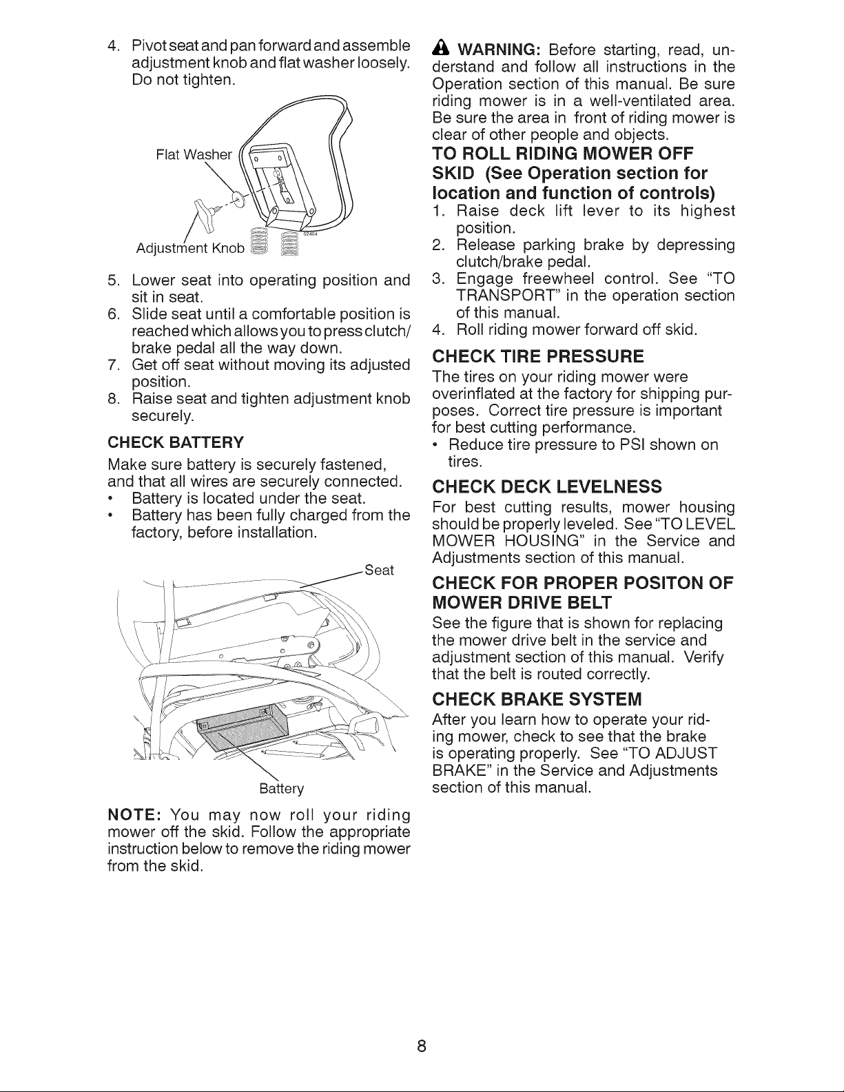
4. Pivot seat and pan forward and assemble
adjustment knob and flat washer loosely.
Do not tighten.
Flat Washer
Adj
5. Lower seat into operating position and
sit in seat.
6. Slide seat until a comfortable position is
reached which allows you to press clutch/
brake pedal all the way down,
7. Get off seat without moving its adjusted
position.
8. Raise seat and tighten adjustment knob
securely.
CHECK BATTERY
Make sure battery is securely fastened,
and that all wires are securely connected.
• Battery is located under the seat.
• Battery has been fully charged from the
factory, before installation.
\
\
\
Battery
_i_ WARNING: Before starting, read, un-
derstand and follow all instructions in the
Operation section of this manual. Be sure
riding mower is in a well-ventilated area.
Be sure the area in front of riding mower is
clear of other people and objects.
TO ROLL RIDING MOWER OFF
SKID (See Operation section for
location and function of controls)
1. Raise deck lift lever to its highest
position.
2. Release parking brake by depressing
clutch/brake pedal.
3. Engage freewheel control. See "TO
TRANSPORT" in the operation section
of this manual.
4. Roll riding mower forward off skid.
CHECK TIRE PRESSURE
The tires on your riding mower were
ovednflated at the factory for shipping pur-
poses. Correct tire pressure is important
for best cutting performance.
• Reduce tire pressure to PSI shown on
tires.
CHECK DECK LEVELNESS
For best cutting results, mower housing
should be properly leveled. See "TO LEVEL
MOWER HOUSING" in the Service and
Adjustments section of this manual.
CHECK FOR PROPER POSITON OF
MOWER DRIVE BELT
See the figure that is shown for replacing
the mower drive belt in the service and
adjustment section of this manual. Verify
that the belt is routed correctly.
CHECK BRAKE SYSTEM
After you learn how to operate your rid-
ing mower, check to see that the brake
is operating properly. See "TO ADJUST
BRAKE" in the Service and Adjustments
section of this manual.
NOTE: You may now roll your riding
mower off the skid, Follow the appropriate
instruction below to remove the riding mower
from the skid.
8

JCHECKLIST
Before you operate your new riding mower,
we wish to assure that you receive the best
performance and satisfaction from this
Quality Product.
Please review the following checklist:
_" All assembly instructions have been
completed.
_" No remaining loose parts in carton.
_" Battery is properly connected.
_" Seat is adjusted comfortably and tight-
ened securely.
_" All tires are properly inflated. (For ship-
ping purposes, the tires were overinflated
at the factory).
_" Be sure mower deck is properly leveled
side-to-side/front-to-rear for best cutting
results. (Tires must be properly inflated
for leveling).
_" Check mower belt. Be sure it is routed
properly around pulleys and inside all belt
keepers.
_/" Check wiring. See that all connections
are still secure and wires are properly
clamped.
_/" Before driving riding mower, be sure free-
wheel control is in "transmission engaged"
position (see "TO TRANSPORT" in the
Operation section of this manual).
While learning how to use your riding mower,
pay extra attention to the following important
items:
_/" Engine oil is at proper level.
_/" Fuel tank is filled with fresh, clean, regular
unleaded gasoline.
_/" Become familiar with all controls, their
location and function. Operate them
before you start the engine.
_/" Be sure brake system is in safe operating
condition.
_/" Be sure Operator Presence System and
Reverse Operation System (ROS) are
working properly (See the Operation and
Maintenance sections in this manual).
9

These symbols may appear on your riding mower or in literature supplied with the prod-
uct. Learn and understand their meaning.
R N H L
REVERSE NEUTRAL HIGH LOW
CHOKE FAST SLOW
IGNITION SWITCH
G o
ENGINE OFF REVERSE ENGINE ON ENGINE START
OVER TEMP FUEL
LIGHT
ATTACHMENT
CLUTCH ENGAGED
BRAKE/CLUTCH
PEDAL
Failure to follow instructions
could result in serious injury or
death, The safety alert symbol
is used to identify safety inform-
ation about hazards which can
result in death, serious injury
and/or property damage,
OPERATION
SYSTEM(ROS)
OIL PRESSURE
ATTACHMENT
CLUTCH DISENGAGED
FREEWHEEL CONTROL
DISENGAGED
FREEWHEEL CONTROL
ENGAGED
BATTERY REVERSE FORWARD
DANGER, KEEP HANDS
AND FEET AWAY
6 @
PARKING BRAKE PARKING BRAKE PARKING BRAKE
LOCKED UNLOCKED
MOWER HEIGHT
MOWER LIFT
®@®@@
KEEP AREA CLEAR SLOPE HAZARDS
(SEE SAFETY RULES SECTION)
DANGER indicates a hazard which, if not avoided,
will result in death or serious injury.
WARNING indicates a hazard which, if not avoided,
could result in death or serious injury.
CAUTION indicates a hazard which, if not avoided,
might result in minor or moderate injury.
CAUTION when used without the alert symbol,
indicates a situation that could result in damage
to the tractor and/or engine.
HOT SURFACES indicates a hazard which,
if not avoided, could result in death, serious injury
and/or property damage.
FIRE indicatesa hazard which, if not avoided,
could result in death, serious injury and/or
property damage.
10

KNOW YOUR RIDING MOWER
READ THIS OWNER'S MANUAL AND SAFETY RULES BEFORE OPERATING
YOUR RIDING MOWER
Compare the illustrations with your riding mower to familiarize yourself with the locations
of various controls and adjustments. Save this manual for future reference.
\
..... ................... 9 "i
.... ........ ,_ Parking
Brake Pedal ,_"\ ,-.... Brake
ROS
"ON"
Deck Clutch
Lever
Lift Lever
Plunger
Height
Adj
Lever
Ignition
Switch
Motion
Control
Lever
Freewheel Control ,,' !("
Our riding mowers conform to the applicable safety standards of the
American National Standards Institute.
DECK CLUTCH LEVER - Used to engage
the mower blade.
BRAKE PEDAL - Used for braking the rid-
ing mower and starting the engine.
HEIGHT ADJUSTMENT LEVER - Used to
adjust mower cutting height.
IGNITION SWITCH - Used for starting and
stopping the engine.
LIFT LEVER PLUNGER - Used to release
height adjustment lever when changing its
position.
PARKING BRAKE LEVER - Locks park-
ing brake into brake position.
MOTION CONTROL LEVER - Selects the
speed and direction of the riding mower.
FREEWHEEL CONTROL - Disengages
transmission for pushing or slowly towing
the riding mower with the engine off.
ROS "ON" POSITION -Allows operation
of mower deck or other powered attach-
ment while in reverse.
11

The operation of any riding mower can result in foreign objects thrown
into the eyes, which can result in severe eye damage. Always wear
safety glasses or eye shields while operating your riding mower or
performing any adjustments or repairs. We recommend a wide vision
safety mask over spectacles or standard safety glasses.
HOW TO USE YOUR RIDING
MOWER
TO SET PARKING BRAKE
Your riding mower is equipped with an opera-
tor presence sensing switch. When engine
is running, any attempt by the operator to
leave the seat without first setting the parking
brake will shut off the engine.
1. Depress brake pedal all the way down
and hold.
2. Depress parking brake lever and release
pressure from brake pedal. Pedal should
remain in brake position. Make sure
parking brake will hold riding mower
secure.
Parking Brake Motion
Peda!-Push Down _/Control
to "Engage ...... _ Lever
Mower Height
Adjustment
NOTE: Under certain conditions when riding
mower is standing idle with the engine run-
ning, hot engine exhaust gases may cause
"browning" of grass. To eliminate this pos-
sibility, always stop engine when stopping
riding mower on grass areas.
,M,
_HiICAUTION: Always stop riding mower
completely, as described above, before
leaving the operator's position.
TO MOVE FORWARD AND BACKWARD
The direction and speed of movement is
controlled by the motion control lever.
1. Start riding mowerwith clutch/brake pedal
depressed and motion control lever in
neutral (N) position.
2. Move motion control lever to desired
position.
3. Slowly release clutch/brake pedal to start
movement.
IMPORTANT: Bring riding mower to a com-
plete stop before shifting or changing gears.
Failure to do so will shorten the useful life of
your transaxle.
Deck Clutch
Lever
"Disengaged"
"Engaged"
Position
Brake Pedal
"Drive"
Position
Deck Clutch
Lever
"Engaged"
Position
Position
STOPPING
MOWER BLADE -
• To stop mower blade, move deck clutch
lever to disengaged position.
GROUND DRIVE-
• Tostop ground drive, depress brake pedal
all the way down.
ENGINE -
• Turn ignition keyto"STOP" position and re-
move key. Always remove keywhen leaving
riding mowerto prevent unauthorized use.
IMPORTANT: Leaving the ignition switch in
any position other than "STOP" will cause
the battery to discharge and go dead.
TO ADJUST MOWER CUTTING HEIGHT
The position of the mower height deck lift
lever determines the cutting height.
• Grasp lift lever.
• Press lift lever plunger with thumb and
move lever to desired position.
The cutting height range is approximately
1-1/2 to 4". The heights are measured from
the ground to the blade tip with the engine
not running. These heights are approximate
and may vary depending upon soil condi-
tions, height of grass and types of grass
being mowed.
• The average lawn should be cut to ap-
proximately 2-1/2" during the cool season
and to over 3" during hot months. For
healthier and better looking lawns, mow
often and after moderate growth.
• For best cutting performance, grass over
6" in height should be mowed twice. Make
the first cut relatively high; the second to
desired height.
12

TO OPERATE MOWER
Your riding mower is equipped with an
operator presence sensing switch. Any
attempt by the operator to leave the seat
with the engine running and the deck clutch
engaged will shut off the engine. You must
remain fully and centrally positioned in the
seat to prevent the engine from hesitating or
cutting off when operating your equipment
on rough, rolling terrain or hills.
1. Select desired height of cut.
2. Start mower blade by engaging deck
clutch lever.
TO STOP MOWER BLADE-
Disengage deck clutch lever.
Deck Clutch Lever
"Disengaged" Position
Mower Height
Adjustment High
Position
Mower Height
Deck :lutch Lever Adjustment
"Engaged" Position Low Position
REVERSE OPERATION SYSTEM (ROS)
Your tractor is equipped with a Reverse
Operation System (ROS). Any attempt by
the operator to travel in the reverse direc-
tion with the deck clutch engaged will shut
off the engine unless ignition key is placed
in the ROS "ON" position.
,_WARNING: Backing up with the deck
clutch engaged while mowing is strongly
discouraged. Turning the ROS "ON", to al-
low reverse operation with the deck clutch
engaged, should only be done when the
operator decides it is necessary to reposi-
tion the machine with the attachment
engaged. Do not mow in reverse unless
absolutely necessary.
USING THE REVERSE OPERATION
SYSTEM -
Only use if you are certain no children or
other bystanders will enter the mowing
area.
1. Move motion control lever to neutral
(N) position.
2. With engine running, turn ignition key
counterclockwise to ROS "ON" posi-
tion.
3. Look down and behind before and
while backing.
4. Slowly move motion control lever to
reverse (R) position to start movement.
5. When use of the ROS is no longer
needed, turn the ignition key clockwise
to engine "ON" position.
ROS "ON" Position
Engine "ON" Position
(Normal Operating)
_I, CAUTION: Do not operate the mower
without either the entire grass catcher, on
mowers so equipped, or the deflector shield
in place.
/
Deflector Shield
13
TO OPERATE ON HILLS
_IWARNING: Do not drive up or down
hills with slopes greater than 15 ° and do not
drive across any slope. Use the slope guide
at the back of this manual.
• Choosethe slowest speed before starting
up or down hills.
• Avoid stopping or changing speed on
hills.
• if stopping is absolutely necessary, push
clutch/brake pedal quicklyto brake position
and engage parking brake.
• Move motion control lever to neutral (N)
position.
• To restart movement, slowly release park-
ing brake and clutch/brake pedal.
• Make all turns slowly.
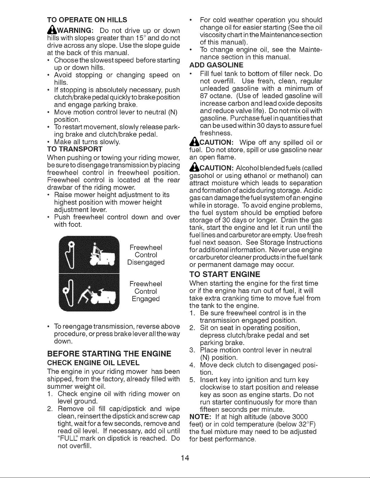
TO TRANSPORT
When pushing or towing your riding mower,
be sure to disengage transmission by placing
freewheel control in freewheel position.
Freewheel control is located at the rear
drawbar of the riding mower.
• Raise mower height adjustment to its
highest position with mower height
adjustment lever.
• Push freewheel control down and over
with foot.
Freewheel
Control
Disengaged
Freewheel
Control
Engaged
• To reengage transmission, reverse above
procedure, or press brake lever all the way
down.
BEFORE STARTING THE ENGINE
CHECK ENGINE OIL LEVEL
The engine in your riding mower has been
shipped, from the factory, already filled with
summer weight oil.
1. Check engine oil with riding mower on
level ground.
2. Remove oil fill cap/dipstick and wipe
clean, reinsert the dipstick and screw cap
tight, wait for a few seconds, remove and
read oil level. If necessary, add oil until
"FULl" mark on dipstick is reached. Do
not overfill.
• For cold weather operation you should
change oil for easier starting (See the oil
viscosity chart in the Maintenance section
of this manual).
• To change engine oil, see the Mainte-
nance section in this manual.
ADD GASOLINE
• Fill fuel tank to bottom of filler neck. Do
not overfill. Use fresh, clean, regular
unleaded gasoline with a minimum of
87 octane. (Use of leaded gasoline will
increase carbon and lead oxide deposits
and reduce valve life). Do not mix oil with
gasoline. Purchase fuel in quantities that
can be used within 30 days to assure fuel
freshness.
_ICAUTION: Wipe off any spilled oil or
fuel. Do not store, spill or use gasoline near
an open flame.
_ICAUTION: Alcohol blended fuels (called
gasohol or using ethanol or methanol) can
attract moisture which leads to separation
and formation of acids during storage. Acidic
gas can damage the fuel system of an engine
while in storage. To avoid engine problems,
the fuel system should be emptied before
storage of 30 days or longer. Drain the gas
tank, start the engine and let it run until the
fuel lines and carburetor are empty. Use fresh
fuel next season. See Storage Instructions
for additional information. Never use engine
or carburetor cleaner products in the fuel tank
or permanent damage may occur.
TO START ENGINE
When starting the engine for the first time
or if the engine has run out of fuel, it will
take extra cranking time to move fuel from
the tank to the engine.
1. Be sure freewheel control is in the
transmission engaged position.
2. Sit on seat in operating position,
depress clutch/brake pedal and set
parking brake.
3. Place motion control lever in neutral
(N) position.
4. Move deck clutch to disengaged posi-
tion.
5. Insert key into ignition and turn key
clockwise to start position and release
key as soon as engine starts. Do not
run starter continuously for more than
fifteen seconds per minute.
NOTE: If at high altitude (above 3000
feet) or in cold temperature (below 32°F)
the fuel mixture may need to be adjusted
for best performance.
14

RECOIL STARTING SYSTEM
This unit is equipped with an engine recoil
starting system. If the battery is too weak
to start engine.
1. Set parking Brake.
2. Turn key to ON position.
3. Make sure unit is in neutral position.
4. Set deck to disengaged position.
5. Pull recoil cord to start engine.
Gasoline Filler
Cap
Starter
Handle
• Do not mow grass when it is wet. Wet
grass will plug mower and leave undesir-
able clumps. Allow grass to dry before
mowing.
• Regulate ground speed by selecting a low
enough gear to give the mower cutting
performance as well as the quality of cut
desired.
• When operating attachments, select a
ground speed that will suit the terrain and
give best performance of the attachment
being used.
MOWING TiPS
• Mower should be properly leveled for best
mowing performance. See "TO LEVEL
MOWER HOUSING" in the Service and
Adjustments section of this manual.
• The left hand side of mower should be
used for trimming.
• Drive sothat clippings are discharged onto
the area that has already been cut. Have
the cut areato the right of the riding mower.
This will result in a more even distribution
of clippings and more uniform cutting.
• When mowing large areas, start byturning
to the right so that clippings will discharge
away from shrubs, fences, driveways,
etc. After one or two rounds, mow in the
opposite direction making left hand turns
until finished.
• If grass is extremely tall, it should be
mowed twice to reduce load and possible
fire hazard from dried clippings. Make
first cut relatively high; the second to the
desired height.
15
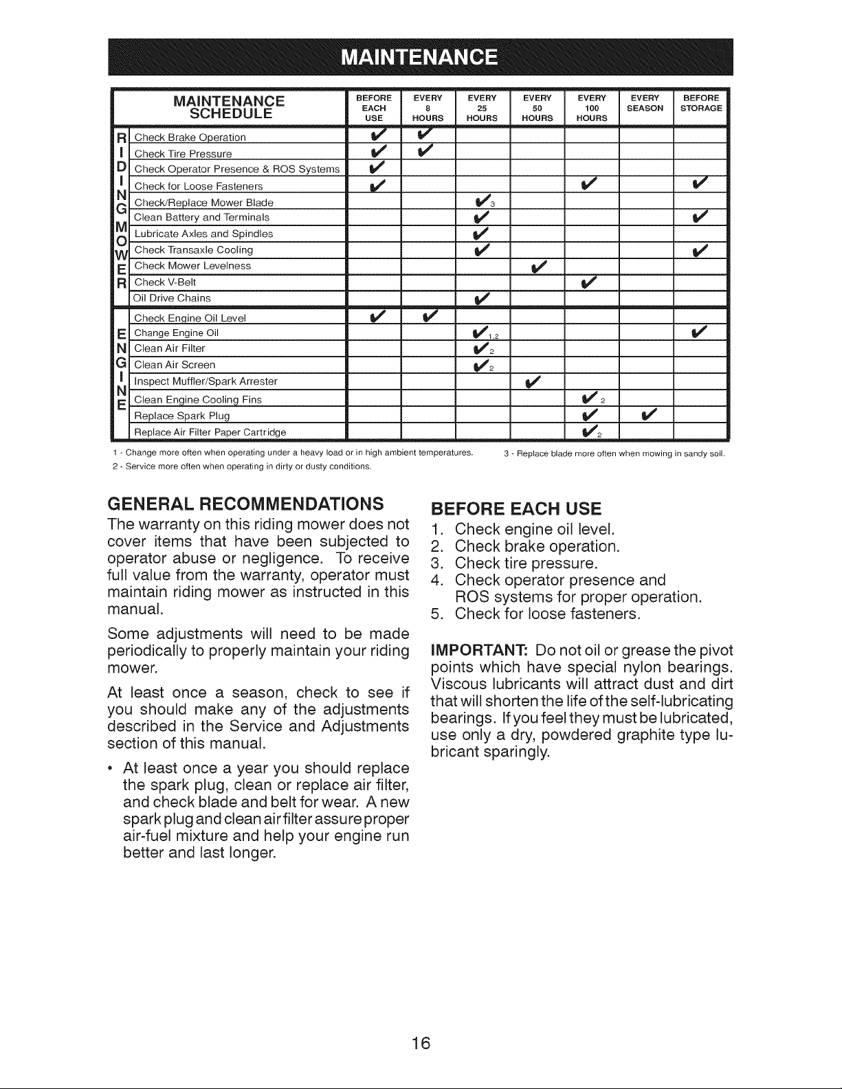
MAINTENANCE BEFORE EVERY EVERY EVERY EVERY EVERY BEFORE
SON EDU LE EACH 8 25 50 100 SEASONSTORAGE
_R Check Brake Operation _ V
I Check Tire Pressure V _ _4
D Check Operator Presence & ROS Systems
N_ Check for Loose Fasteners _ _
G ChecWReplace Mower Blade V_3
Clean Battery and Terminals _' _f
_) Lubricate Axles and _##
i_ Check Transaxle Cooling if _#4
Check Mower Levelness
R Check V-Belt V _
Oil Drive Chains V _
Check En,qine Oil Level
E Change Engine Oil
N Clean Air Filter
G Clean Air Screen
N_ Inspect Muffler/SparkArrester
E Clean Engine Cooling Fins
Replace Spark Plug
Replace Air Filter Paper Cartridge
1 - Change more often when operating under a heavy load or in high ambient temperatures.
2 - Service more often when operating in dirty or dusty conditions.
Spindles
USE HOURS HOURS HOURS HOURS
v' v'
_1.2
its
V' V'
3 - Replace blade more often when mowing in sandy soil.
I/
GENERAL RECOMMENDATIONS
The warranty on this riding mower does not
cover items that have been subjected to
operator abuse or negligence. To receive
full value from the warranty, operator must
maintain riding mower as instructed in this
manual.
Some adjustments will need to be made
periodically to properly maintain your riding
mower.
At least once a season, check to see if
you should make any of the adjustments
described in the Service and Adjustments
section of this manual.
• At least once a year you should replace
the spark plug, clean or replace air filter,
and check blade and belt for wear. A new
spark plug and clean air filter assure proper
air-fuel mixture and help your engine run
better and last longer.
BEFORE EACH USE
1. Check engine oil level.
2. Check brake operation.
3. Check tire pressure.
4. Check operator presence and
ROS systems for proper operation.
5. Check for loose fasteners.
IMPORTANT: Do not oil or grease the pivot
points which have special nylon bearings.
Viscous lubricants will attract dust and dirt
that will shorten the life of the self-lubricating
bearings. If you feel they must be lubricated,
use only a dry, powdered graphite type lu-
bricant sparingly.
16
RIDING MOWER
Always observe safety rules when performing
any maintenance.
BRAKE OPERATION
If riding mower requires more than four (4)
feet to stop at highest speed in highest gear
on a level, dry concrete or paved surface, then
brake must be serviced. (See "TO ADJUST
BRAKE" in the Service and Adjustments
section of this manual).
TIRES
• Maintain proper air pressure in all tires
(See PSI on tires).
• Keep tires free of gasoline, oil, or insect
control chemicals which can harm
rubber.
• Avoid stumps, stones, deep ruts, sharp
objects and other hazards that may cause
tire damage.
NOTE: To seal tire punctures and prevent
flat tires due to slow leaks, tire sealant may
be purchased from your local parts dealer.
Tire sealant also prevents tire dry rot and
corrosion.
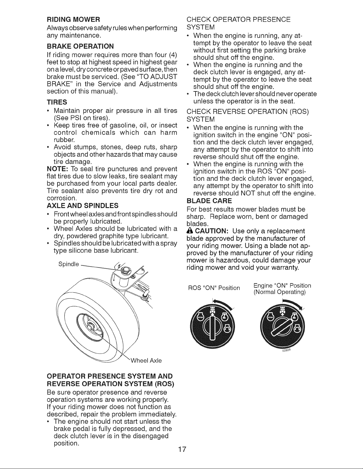
AXLE AND SPINDLES
• Front wheel axles and front spindles should
be properly lubricated.
• Wheel Axles should be lubricated with a
dry, powdered graphite type lubricant.
• Spindles should be lubricated with a spray
type silicone base lubricant.
Spindle
CHECK OPERATOR PRESENCE
SYSTEM
• When the engine is running, any at-
tempt by the operator to leave the seat
without first setting the parking brake
should shut off the engine.
• When the engine is running and the
deck clutch lever is engaged, any at-
tempt by the operator to leave the seat
should shut off the engine.
• The deck clutch lever should never operate
unless the operator is in the seat.
CHECK REVERSE OPERATION (ROS)
SYSTEM
• When the engine is running with the
ignition switch in the engine "ON" posi-
tion and the deck clutch lever engaged,
any attempt by the operator to shift into
reverse should shut off the engine.
• When the engine is running with the
ignition switch in the ROS "ON" posi-
tion and the deck clutch lever engaged,
any attempt by the operator to shift into
reverse should NOT shut off the engine.
BLADE CARE
For best results mower blades must be
sharp. Replace worn, bent or damaged
blades.
_1, CAUTION: Use only a replacement
blade approved by the manufacturer of
your riding mower. Using a blade not ap-
proved by the manufacturer of your riding
mower is hazardous, could damage your
riding mower and void your warranty.
Axle
OPERATOR PRESENCE SYSTEM AND
REVERSE OPERATION SYSTEM (ROS)
Be sure operator presence and reverse
operation systems are working properly.
If your riding mower does not function as
described, repair the problem immediately.
• The engine should not start unless the
brake pedal is fully depressed, and the
deck clutch lever is in the disengaged
position.
ROS "ON" Position
17
Engine "ON" Position
(Normal Operating)
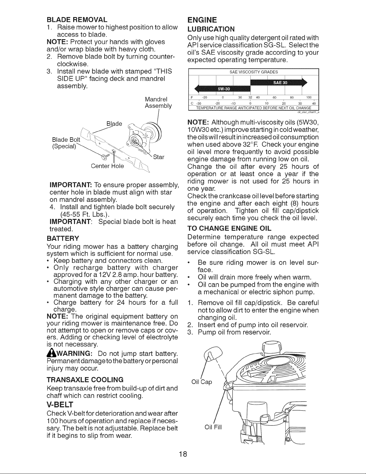
BLADE REMOVAL
1. Raise mowerto highest position to allow
access to blade.
NOTE: Protect your hands with gloves
and/or wrap blade with heavy cloth.
2. Remove blade bolt by turning counter-
clockwise.
3. Install new blade with stamped "THIS
SIDE UP" facing deck and mandrel
assembly.
Mandrel
Assembly
ENGINE
LUBRICATION
Only use high quality detergent oil rated with
API service classification SG-SL Select the
oil's SAE viscosity grade according to your
expected operating temperature.
SAE VISCOSITY GRADES
F -20 0 30 32 40 60 80 100
o -_0 -2; -1; ; 1; _0 _o 4;
TEMPERATURE RANGE ANTICIPATED BEFORE NEXT OIL CHANGE
I
oilviscchartl
Blade
Blade
"Star
Center Hole
IMPORTANT: To ensure proper assembly,
center hole in blade must align with star
on mandrel assembly.
4. Install and tighten blade bolt securely
(45-55 Ft. Lbs.).
IMPORTANT: Special blade bolt is heat
treated.
BATTERY
Your riding mower has a battery charging
system which is sufficient for normal use.
• Keep battery and connectors clean,
• Only recharge battery with charger
approved for a 12V 2.8 amp, hour battery,
• Charging with any other charger or an
automotive style charger can cause per-
manent damage to the battery,
• Charge battery for 24 hours for a full
charge.
NOTE: The original equipment battery on
your riding mower is maintenance free, Do
not attempt to open or remove caps or cov-
ers, Adding or checking level of electrolyte
is not necessary.
_i, WARNING: Do not jump start battery.
Permanent damage to the battery or personal
injury may occur.
NOTE: Although multi-viscosity oils (5W30,
10W30 etc.) improve starting in cold weather,
the oils will result in increased oil consumption
when used above 32°R Check your engine
oil level more frequently to avoid possible
engine damage from running low on oil.
Change the oil after every 25 hours of
operation or at least once a year if the
riding mower is not used for 25 hours in
one year.
Check the crankcase oil level before starting
the engine and after each eight (8) hours
of operation. Tighten oil fill cap/dipstick
securely each time you check the oil level.
TO CHANGE ENGINE OIL
Determine temperature range expected
before oil change. All oil must meet API
service classification SG-SL.
• Be sure riding mower is on level sur-
face.
• Oil will drain more freely when warm.
• Oil can be pumped from the engine with
a mechanical or electric siphon pump.
1. Remove oil fill cap/dipstick. Be careful
not to allow dirt to enter the engine when
changing oil.
2. Insert end of pump into oil reservoir.
3. Pump oil from reservoir.
TRANSAXLE COOLING
Keep transaxle free from build-up of dirt and
chaff which can restrict cooling.
V-BELT
Check V-belt for deterioration and wear after
100 hours of operation and replace if neces-
sary. The belt is not adjustable. Replace belt
if it begins to slip from wear.
Oil Cap
Oil Fill
18
.
Refill engine with oil through oil fill dipstick
tube. Pour slowly. Do not overfill. For
approximate capacity see "PRODUCT
SPECIFICATIONS"section of this manual.
.
Use gauge on oil fill cap/dipstick for
checking level. For accurate reading,
tighten dipstick cap securely onto the
tube before removing dipstick. Keep oil
at "FULl" line on dipstick. Tighten cap
onto the tube securely when finished.
AIR FILTER
Your engine will not run properly using a
dirty air filter. Replace the air filter every
100 hours of operation or every season,
whichever occurs first. Service air cleaner
more often under dusty conditions.
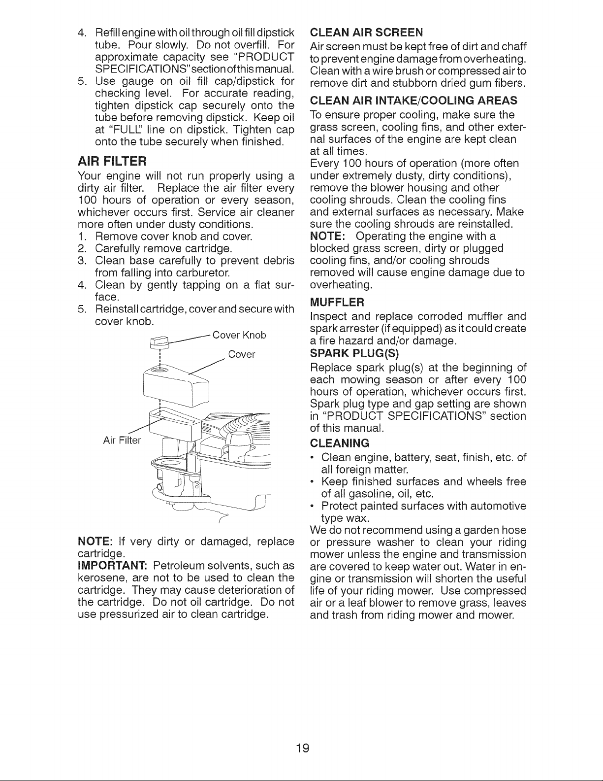
1. Remove cover knob and cover.
2. Carefully remove cartridge.
3. Clean base carefully to prevent debris
from falling into carburetor.
4. Clean by gently tapping on a flat sur-
face.
5. Reinstall cartridge, cover and secure with
cover knob.
11 Cover Knob
Cover
Air Filter
NOTE: If very dirty or damaged, replace
cartridge.
IMPORTANT: Petroleum solvents, such as
kerosene, are not to be used to clean the
cartridge. They may cause deterioration of
the cartridge. Do not oil cartridge. Do not
use pressurized air to clean cartridge.
CLEAN AIR SCREEN
Air screen must be kept free of dirt and chaff
to prevent engine damage from overheating.
Clean with a wire brush or compressed airto
remove dirt and stubborn dried gum fibers.
CLEAN AIR INTAKE/COOLiNG AREAS
To ensure proper cooling, make sure the
grass screen, cooling fins, and other exter-
nal surfaces of the engine are kept clean
at all times.
Every 100 hours of operation (more often
under extremely dusty, dirty conditions),
remove the blower housing and other
cooling shrouds. Clean the cooling fins
and external surfaces as necessary. Make
sure the cooling shrouds are reinstalled.
NOTE: Operating the engine with a
blocked grass screen, dirty or plugged
cooling fins, and/or cooling shrouds
removed will cause engine damage due to
overheating.
MUFFLER
Inspect and replace corroded muffler and
spark arrester (if equipped) as it could create
a fire hazard and/or damage.
SPARK PLUG(S)
Replace spark plug(s) at the beginning of
each mowing season or after every 100
hours of operation, whichever occurs first.
Spark plug type and gap setting are shown
in "PRODUCT SPECIFICATIONS" section
of this manual.
CLEANING
• Clean engine, battery, seat, finish, etc. of
all foreign matter.
• Keep finished surfaces and wheels free
of all gasoline, oil, etc.
• Protect painted surfaces with automotive
type wax.
We do not recommend using a garden hose
or pressure washer to clean your riding
mower unless the engine and transmission
are covered to keep water out. Water in en-
gine or transmission will shorten the useful
life of your riding mower. Use compressed
air or a leaf blower to remove grass, leaves
and trash from riding mower and mower.
19
&
WARNING: TO AVOID SERIOUS INJURY, BEFORE PERFORMING ANY
SERVICE OR ADJUSTMENTS:
1. Depress clutch/brake pedal fully and set parking brake.
2. Place motion control lever in neutral (N) position.
3. Place deck clutch in "DISENGAGED" position.
4. Turn ignition key to "STOP" and remove key.
5. Make sure the blade and all moving parts have completely stopped.
6. Disconnect spark plug wire from spark plug and place wire where it cannot
come in contact with plug.
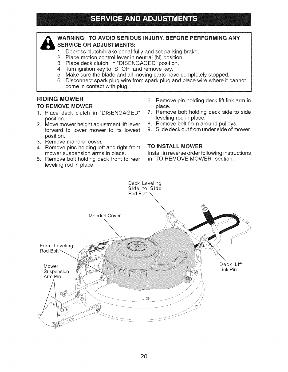
RIDING MOWER
TO REMOVE MOWER
1. Place deck clutch in "DISENGAGED"
position.
2. Move mower height adjustment lift lever
forward to lower mower to its lowest
position.
3. Remove mandrel cover.
4. Remove pins holding left and right front
mower suspension arms in place.
5. Remove bolt holding deck front to rear
leveling rod in place.
Deck Leveling
Side to Side
Rod Bolt
Mandrel Cover
6. Remove pin holding deck lift link arm in
place.
7. Remove bolt holding deck side to side
leveling rod in place.
8. Remove belt from around pulleys.
9. Slide deck out from under side of mower.
TO INSTALL MOWER
Install in reverse order following instructions
in "TO REMOVE MOWER" section.
Mower
Suspension
Arm Pin
Deck Lift
Link Pin
20

TO LEVEL MOWER HOUSING
Adjust the mower while riding mower is
parked on level ground or driveway. Make
sure tires are properly inflated (See side
of tire for proper PSI). If tires are over or
underinflated, you will not properly adjust
your mower.
SIDE-TO-SIDE ADJUSTMENT
• Raise mower to its highest position.
• Measure distance "A" from bottom edge
of mower to ground level at front corners
of mower.
• To raise the right side ofthe mower, tighten
lift link adjustment nut.
• To Iowerthe right side ofthe mower, loosen
lift link adjustment nut.
NOTE: Each full turn of adjustment nut will
change mower height about 3/16".
Bottom Edge of Bottom Edge of
Mower to Ground Mower to Ground
A;L!!il If!ILJ
• Recheck measurements after adjusting.
FRONT-TO-BACK ADJUSTMENT
iMPORTANT: Deck must be level side-to
side.
To obtain the best cutting results, the mower
housing should be adjusted so that the front is
approximately 1/8" to 1/2" lower than the rear
when the mower is in its highest position.
Check adjustment on right side of riding
mower. Measure distance"F" directly in front
and behind the mandrel at bottom edge of
mower housing as shown.
Nut "G"
TO REPLACE MOWER BLADE DRIVE
BELT
MOWER DRIVE BELT REMOVAL
1. Park riding mower on a level surface.
2. Set parking brake.
3. Lower mower to its lowest position.
4. Remove mandrel cover from mower
deck.
5. Remove rear engine plate from unit.
6. Remove rear belt keeper from unit.
7. Carefully roll belt over the top of the
mower blade mandrel.
8. Remove belt from idler pulleys.
Mower Drive Belt
Keeper
• To lower front of mower housing turn nuts
"G" and "H" clockwise.
• When distance "F" is 1/8" to 1/2" lower
at front than rear, tighten nut "H" against
trunnion on front link.
• To raise front of mower housing turn nuts
"G" and "H" counter clockwise.
• When distance "F" is 1/8" to 1/2" lower
at front than rear, tighten nut "H" against
trunnion on front link.
NOTE: Each full turn of "G" will change "F"
by approximately about 3/8".
• Recheck side-to-side adjustment.
Idler Pulleys
9. Check idler pulleys to see that they rotate
freely.
10. Remove belt from rear drive pulley.
MOWER DRIVE BELT INSTALLATION
Install in reverse order following instruc-
tions in "MOWER DRIVE BELT REMOVAL"
section.
21

TO ADJUST BRAKE
Your riding mower is equipped with an
adjustable brake system which is mounted
on the right side of the transaxle. If riding
mower requires more than (4) feet stop-
ping distance in highest gear on a lever dry
concrete or paved surface, then brake must
be adjusted.
1. Park riding mower on a level surface.
2. Release brake/parking pedal.
3. Measure distance between rotor and
brake pad if distance between rotor and
brake pad is more than .02" gap brake
needs to be adjusted.
4. Tighten caliper nut until .02" gap is
reached.
REAR WHEEL
1. Block up Rear axle securely.
2. Remove dust cover, retaining ring, wash-
er, and square key while pulling tire off.
3. Repair tire and reassemble.
4. Replace square keywhile putting tire back
on, then replace washer and retaining ring
securely in axle groove ,when pushing
tire back onto shaft reach under and pull
chain sprocket toward you to ease tire
replacement.
NOTE: To seal tire punctures and prevent
flat tires due to slow leaks, purchase and
use tire sealant. Tire sealant also prevents
tire dry rot and corrosion.
Rotor
Pad
Nut
NOTE: Feeler gauge may be necessary to
get correct measurement.
TO ADJUST STEERING WHEEL
ALIGNMENT
If steering wheel crossbars are not horizontal
(left to right) when wheels are positioned
straight forward, move steering wheel
and reassemble per instructions in the
"INSTALL STEERING COLUMN"section of
this manual.
TO REMOVE WHEEL FOR REPAIRS
FRONT WHEEL
1. Block up front axle securely.
2. Remove dust cover, retaining ring, and
washer to allow wheel removal.
3. Repair tire and reassemble.
4. Replace washer and retaining ring
securely in axle groove.
Washer
Retaining
Ring\
_ Square Key
Dust
Cover (rear wheel only)
TO START ENGINE WITH A WEAK
BATTERY
_,CAUTION: Lead-acid batteries gener-
ate explosive gases. Keep sparks, flame
and smoking materials away from batteries.
Always wear eye protection when around
batteries.
If your battery is too weak to start the engine,
it should be recharged. (See "BATTERY" in
the Maintenance section of this manual).
NOTE: This unit is equipped with an engine
recoil starting system that can be used ifthe
battery is too weak to start. See "RECOIL
STARTING SYSTEM" in operation section
of this manual.
REPLACING BATTERY
_I, WARNING" Do not short battery termi-
nals by allowing a wrench or any other object
to contact both terminals at the same time.
Before connecting battery, remove metal
bracelets, wristwatch bands, rings, etc.
Positive terminal must be connected
first to prevent sparking from accidental
grounding.
22

1. Lift seat for bolt access.
2. Disconnect BLACK battery cable then
RED battery cable.
3. Remove battery bracket bolt.
4. Install new battery with terminals facing
to the right, and away from seat as
shown.
5. Reinstall battery bracket and bolt.
6. First connect RED battery cable to posi-
tive (+) battery terminal.
7. Connect BLACK grounding cable to
negative (-) battery terminal.
Fender
ENGINE
Your engine speed has been factory set. Do
not attempt to increase engine speed or it
may result in personal injury. If you believe
that the engine is running too fast ortoo slow,
take your riding mower to a qualified service
center for repair and/or adjustment.
Your carburetor is not adjustable. If your
engine does not operate properly due to
suspected carburetor problems, take your
riding mower to a qualified service center
for repair and/or adjustment.
IMPORTANT: Never tamper with the engine
governor, which is factory set for proper en-
gine speed. Overspeeding the engine above
the factory high speed setting can be danger-
ous. If you think the engine-governed high
speed needs adjusting, contact a qualified
service center, which has proper equipment
and experience to make any necessary
adjustments.
Battery
Bracket
INTERLOCKS AND RELAYS
Loose or damaged wiring may cause your
riding mower to run poorly, stop running, or
prevent it from starting.
• Check wiring. Make sure all wiring and
connectors are secure.
TO REPLACE FUSE
Replace with 4 amp. or 5 amp. automotive
type plug-in fuse. The fuse holder is located
under the fender.
23

Immediately prepare your riding mower for
storage at the end of the season or if the
riding mower will not be used for 30 days
or more.
4_I, WARNING: Neverstorethe riding mower
with gasoline in the tank inside a building
where fumes may reach an open flame or
spark. Allow the engineto cool before storing
in any enclosure.
MOWER
Remove deck from mower for winter stor-
age. When mower is to be stored for a
period of time, clean it thoroughly, remove
all dirt, grease, leaves, etc. Store in a clean,
dry area.
1. Clean entire riding mower (See "CLEAN-
ING" in the Maintenance section of this
manual).
2. Inspect and replace belt, if necessary
(See belt replacement instructions in the
Service and Adjustments section of this
manual).
3. Lubricate as shown in the Maintenance
section of this manual.
4. Be sure that all nuts, bolts and screws
are securely fastened. Inspect moving
parts for damage, breakage and wear.
Replace if necessary.
5. Touch up all rusted or chipped paint
surfaces; sand lightly before painting.
BATTERY
o
Fully charge the battery for storage.
o
If battery is removed from riding mower
for storage, do not store battery directly
on concrete or damp surfaces.
ENGINE
FUEL SYSTEM
IMPORTANT: It is important to prevent
gum deposits from forming in essential fue!
system parts such as carburetor, fuel hose,
ortank during storage. Also, alcohol blended
fuels (called gasohol or using ethanol or
methanol) can attract moisture which leads
to separation and formation of acids during
storage. Acidic gas can damage the fuel
system of an engine while in storage.
• Empty the fuel tank by starting the engine
and letting it run until the fuel lines and
carburetor are empty.
• Never use engine or carburetor cleaner
products in the fuel tank or permanent
damage may occur.
• Use fresh fue! next season.
NOTE: Fuel stabilizer is an acceptable al-
ternative in minimizing the formation of fuel
gum deposits during storage. Add stabilizer
to gasoline in fuel tank or storage container.
Always followthe mix ratio found on stabilizer
container. Run engine at least 10 minutes
after adding stabilizer to allow the stabilizer to
reach the carburetor. Do not empty the gas
tank and carburetor if using fuel stabilizer.
ENGINE OIL
Drain oil (with engine warm) and replace
with clean engine oil. (See "ENGINE" in the
Maintenance section of this manual).
CYLINDER(S)
1. Remove spark plug(s).
2. Pour one ounce of oil through spark plug
hole(s) into cylinder(s).
3. Turn ignition key to "START" position for
a few seconds to distribute oil.
4. Replace with new spark plug(s).
OTHER
• Do not store gasoline from one season to
another.
• Replace your gasoline can ifyour can starts
to rust. Rust and/or dirt in your gasoline
will cause problems.
• If possible, store your riding mower indoors
and cover it to give protection from dust
and dirt.
• Cover your riding mower with a suitable
protective cover that does not retain mois-
ture. Do not use plastic. Plastic cannot
breathe which allows condensation to form
and will cause your riding mower to rust.
IMPORTANT:
while engine
warm.
Never cover riding mower
and exhaust areas are still
24

TROUBLESHOOTING CHART:
PROBLEM CAUSE CORRECTION
Will not start
1 Out of fuel.
2 Bad spark plug.
3 Dirty air filter.
4 Water in fuel.
5 Loose or damaged wiring.
6 Engine valves out of adjustment.
1 Fill fuel tank.
2 Replace spark plug.
3 Clean/replace air filter.
4 Empty fuel tank and carburetor,
refill tank with fresh gasoline and
replace fuel filter.
5 Check all wiring.
6 Contact a qualified service center.
Hard to start
Engine will not
turn over
Engine clicks but
will not start
Loss of power
Excessive vibration
1 Dirty air filter.
2 Bad spark plug.
3 Weak or dead battery.
4 Stale or dirty fuel.
5 Loose or damaged wiring.
6 Engine valves out of adjustment.
1 Clutch/brake pedal not depressed.
2 Deck clutch is engaged.
3 Weak or dead battery.
4 Blown fuse.
5 Corroded battery terminals.
6 Loose or damaged wiring.
7 Faulty ignition switch.
8 Faulty solenoid or starter.
9 Faultyoperatorpresenceswitch(es).
1 Weak or dead battery.
2 Corroded battery terminals.
3 Loose or damaged wiring.
4 Faulty solenoid or starter.
1 Cutting too much grass/too fast.
2 Build-up of grass, leaves and trash
under mower.
3 Dirty air filter.
4 Low oil level/dirty oil.
5 Faulty spark plug.
6 Stale or dirty fuel.
7 Water in fuel.
8 Spark plug wire loose.
9 Dirty engine air screen/fins.
10 Dirty/clogged muffler.
11 Loose or damaged wiring.
12 Engine valves out of adjustment.
1 Worn, bent or loose blade.
2 Bent blade mandrel.
3 Loose/damaged part(s).
1 Clean/replace air filter.
2 Replace spark plug.
3 Recharge or replace battery.
4 Empty fuel tank and refill tank
with fresh, clean gasoline.
5 Check all wiring.
6 Contact a qualified service center.
1 Depress clutch/brake pedal.
2 Disengage deck clutch.
3 Recharge or replace battery.
4 Replace fuse.
5 Clean battery terminals.
6 Check all wiring.
7 Check/replace ignition switch.
8 Check/replace solenoid or starter.
9 Contact a qualified service center.
1 Recharge or replace battery.
2 Clean battery terminals.
3 Check all wiring.
4 Check/replace solenoid or starter.
1 Raise cutting height/reduce speed.
2 Clean underside of mower
housing.
3 Clean/replace air filter.
4 Check oil level/change oil.
5 Clean & regap or changespark plug.
6 Empty fuel tank and refill tank
with fresh, clean gasoline.
7 Empty fuel tank and carburetor,
refill tank with fresh gasoline.
8 Connect & tighten spark plug wire.
9 Clean engine air screen/fins.
10 Clean/replace muffler.
11 Check all wiring.
12 Contact a qualified service center.
Replace blade. Tighten blade
1 bolt.
2 Contact a qualified service center.
3 Tighten loose part(s).
Replace damaged parts.
25

TROUBLESHOOTING CHART:
PROBLEM CAUSE
Engine continues to
run when operator
leaves seat with atta=
chment clutch engaged
Poor cut =uneven
cutting
Mower blade will
not rotate
Poor grass
discharge
1 Faulty operator-safety presence
control system.
1 Worn, bent or loose blade.
2 Mower deck not level.
3 Buildup of grass, leaves, and trash
under mower.
4 Bent blade mandrel.
5 Clogged mower deck vent from
build-up of grass, leaves, and
trash around mandrel.
1 Obstruction in clutch mechanism.
2 Worn/damaged mower drive belt.
3 Frozen idler pulley.
4 Frozen blade mandrel.
1 Travel speed too fast.
2 Wet grass.
3 Mower deck not level.
4 Low/uneven tire air pressure.
5 Worn, bent or loose blade.
6 Buildup of grass, leaves and
trash under mower.
7 Mower drive belt worn.
8 Blade improperly installed.
9 Improper blade used.
10 Clogged mower deck vent holes
from buildup of grass, leaves, and
trash around mandrels.
CORRECTION
1
Check wiring, switches and
connections. If not corrected,
contact a qualified service center.
1 Replace blade. Tighten blade bolt.
2 Level mower deck.
3 Clean underside of mower
housing.
4 Contact a qualified service center.
5 Clean around mandrels to
open vent holes.
1 Remove obstruction.
2 Replace mower drive belt.
3 Replace idler pulley.
4 Contact a qualified service center.
1 Shift to slower speed.
2 Allow grass to dry before mowing.
3 Level mower deck.
4 Check tires for proper PSI.
5 Replace/sharpen blade. Tighten
blade bolt.
6 Clean underside of mower
housing.
7 Replace mower drive belt.
8 Reinstall blade sharp edge down.
9 Replace with blade listed in
this manual.
10 Clean around mandrels to
open vent holes.
Battery will not 1 Bad battery cell(s).
charge 2 Poor cable connections.
3 Faulty alternator.
Loss of drive 1 Freewheel control in
"DISENGAGED" position.
2 Axle key missing.
Engine dies when 1 Reverse operation system (ROS)
tractor is shifted is not "ON" while mower or other
into reverse attachment is engaged.
26
1 Replace battery.
2 Check/clean all connections.
3 Replace alternator.
1 Place freewheel control in
"ENGAGED" position.
2 Install axle key at rear wheel. See
"TO REMOVE WHEEL" in the
Service and Adjustments section.
1 Turn ignition key to ROS "ON"
position. See Operation section.

SCHEMATIC
RIDING MOWER --CATALOG NO. 28600
SCH21
FUSE-5A ,!_
RED
!1 ....... ; .....
| _ / / SAFETY START MODULE I
BATTERY
STARTER
RELAY STARTER
WHITE
r ........ I
,=_--, ,__.
BLACK
o,, ,, ,, , I /
E-I I _____ I _ _ I _, I _A B C D E F _ I
L_ r, ', _ / (3- ' . :T
REVERSE SWITCH , '-J _ | LY 'J ,
NOT IN REVERSE ................. '
YELLOW I BLACK
, :! ] SHORTING CONNECTOR
t t
t ....... t
j ',
,, ,,
i L I
...... _ _AN-O-T Q_22CUPIED) .....
_ SEAT SWITCH
.......... t
i
t
,I
11
q
,1
IGNITION SWITCH
POSITION CIRCUIT "MAKE"
OFF M-G-A 1
RUN/OVERRIDE B+A1
RUN B+A1 L-A2
START B = S + A1
IGNITION %
UNIT •
CHARGING SYSTEM OUTPUT 28 VOLTS AC MIN ,,_:3600 RPM
5 AMP DC _l 3600 RPM (CHARGING SYSTEM DISCONNECTED)
SAFETY START MODULE
7
VIE\_, ED FROM MATING SIDE
SPARK PLUG
DIODE
WIRING INSULATED CLIPS
NOTE: IF WIRING INSULATED CLIPS
WERE REMOVED FOR SERVICING OF
UNIT, THEY SHOULD BE RE-INSTALLED
TO PROPERLY SECURE YOUR WIRING.
q
q
GAP
STATOR
/,
C)-
REMOVABLE
CONNECTIONS
®
NON-REMOVABLE
CONNECTIONS
27
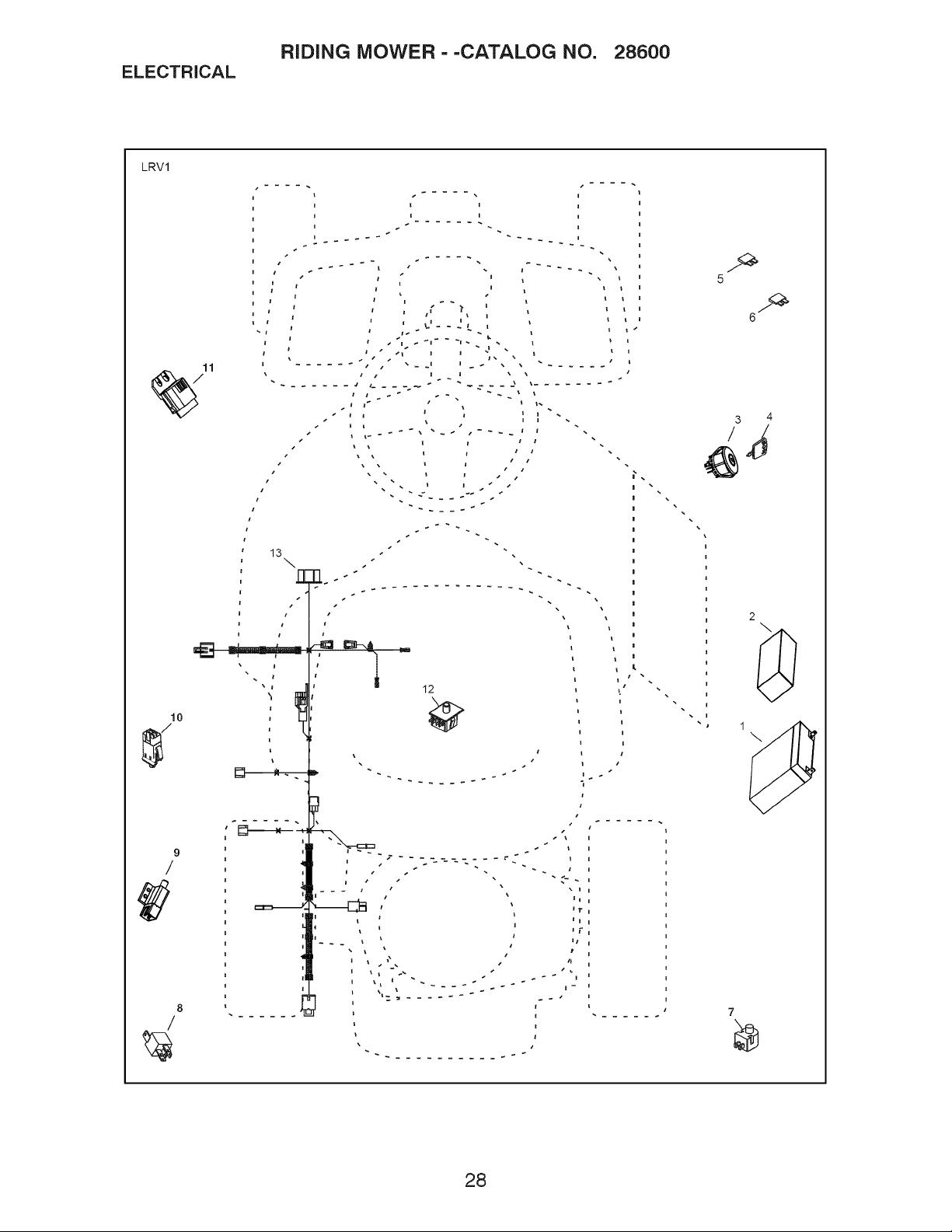
ELECTRICAL
LRV1
RIDING MOWER--CATALOG NO. 28600
J t m j
i g J _ i
r i ! i i
11
%
5
3 4
...., :i i ,
2
\
12
10
9
/
8
7
28

ELECTRICAL
RIDING MOWER --CATALOG NO. 28600
KEY PART
NO. NO.
1 437070
2 425416
3 193350
4 411934
5 433330
6 425937
7 160784
8 431542
9 109553X
10 176138
11 431846
12 192749
13 428477
NOTE: All component dimensions given in U.S. inches
1 inch = 25.4 mm
DESCRIPTION
BATTERY,
FOAM, POLYURETHANE
SWITCH, IGN, DLTA, P-IN, ROS
KEY, MOLDED
FUSE, 5A
FUSE, 40A
SWITCH, PLUNGER, NO, OLIVE
RELAY, 40A
SWITCH, INTLK,CL, MWR, GRY
SWITCH, INTERLOCK, NONC,GRAY
MODULE, STARTING, RECOIL, LRV
SWITCH, SEAT, DP, ROS
HARNESS, IGN, ELECTSTART, LRV
29

CHASSIS
RIDING MOWER --CATALOG NO. 28600
lO
//
,/
42
14 ..-
45 ..........
#
LRV-Chassis f r2
@
30

CHASSIS
RIDING MOWER--CATALOG NO. 28600
KEY PART
NO. NO. DESCRIPTION
1 428048
2 428247
3 428244
4 428346
5 428110
6 428109
7 428040
8 428576
9 428856
10 195530
11 174648X431
12 428248
13 428251X665
14 428250
15 428249
16 428241X665
17 428348
18 428047
-- 432389
-- 435674
19 428986
20 428046
21 429815
22 428826
23 149846
24 416358
25 72140424
26 73510400
27 430087
28 428301
29 430817
30 430470
31 430469
32 150406
33 124181X
34 121250X
35 72050412
36 127018X
37 19171912
38 166369
39 134300
40 121248X
41 123976X
42 171852
43 73800500
44 428243
45 17000512
46 17490508
47 86777
48 408981
49 17060516
50 165492
WELDMENT, CHASSIS
SUPPORT, AXEL LH
SUPPORT, AXEL RH
SHIELD, TRANSAXLE FRONT
BRACE, AXLE CROSS
COVER, FRICTION DRIVE
PLATE, ENGINE
BRACKET, CHASSIS FRONT
BRACKET, STEERING SUPPORT
PAN, SEAT
BRACKET, SWITCH MOUNTING
BOOT, DUST
COVER, FOOT REST
STRUCTURE, FOOT REST
SUPPORT, FOOT REST
FENDER, CONTROL
GUARD, ENGINE
ENGINE, (NON-CALIFORNIA) 12S907-1411 -B1
ENGINE, (CALIFORNIA) 121S07-1415-F1
ENGINE, (CANADA) 12S907-1463-B1
KEEPER, BELT
BRACKET, BATTERY
LEVER, SWITCH
DECK CLUTCH ASM
KNOB
SCREW, NO. 10
BOLT, CARRIAGE 1/4-20 X 3
NUT, 1/4-20
SPACER, ENGINE
DISC, FRICTION ASM
BOLT, SCKT HD 3/8-24 X 1 .25
BEARING
SPACER, NEUTRAL
BOLT, 3/8-16 X .280
SPRING, SEAT
SPRING
BOLT, 1/4-20 X 1 1/2
BOLT, SHOULDER
WASHER, 17/32 X 1 3/16
KNOB, SEAT
SPACER
BUSHING, NYLON SNAP
NUT, LOCK
BOLT, 5/16-18 SHOULDER
NUT, 5/16-18
SEAT
BOLT, 5/16-18 X 3/4
BOLT, 5/16-18 X 1/2
SCREW,
BEARING, FLANGE, BALL
SCREW, 5/16-18 Xl
BOLT, SHOULDER, 5/16-18 x .561
NOTE: Allcomponentdimensions givenin U.S. inches
1 inch = 25.4 mm
31

DRIVE
RIDING MOWER--CATALOG NO. 28600
LRV-Drive 1 r3
/70
\38
32

DRIVE
KEY
NO.
1
2
3
4
5
6
7
8
10
11
12
13
14
15
16
17
18
19
2O
21
22
23
24
25
26
27
28
29
3O
31
32
33
34
35
36
37
38
PART
NO.
436144
428268×613
121748×
12000001
123583X
427939
428069
427873
12100009
428876
1370H
430645
430845
427946
9159R
427926
428106
424759
430870
427997
428077
428076
431374
427995
428303
429816
429053
428302
174840
183900
429055
428464
428461
428462
196492×428
72110406
73800400
165492
RIDING MOWER--CATALOG NO. 28600
KEY PART
DESCRIPTION NO. NO.
SERVICE KIT, TRANSAXLE 39 74780412
WHEEL ASM (REAR) 40 10040400
WASHER, 16 GA. 41 19091210
E-CLIP 42 166002
KEY. SQUARE 43 73680400
WELDMENT. DRIVE AXLE 45 17490436
CHAIN DRIVE 46 19091016
SPROCKET. 9 TOOTH SPLINED 47 17490420
RING, SNAP 48 430249
DIFFERENTIAL ASM 49 430245
WASHER, THRUST 50 428021
CHAIN, PRIMARY DRIVE 51 430247
BUSHING 52 428078
BRACKET, CARRIER 53 77010810
BEARING ASM 54 428019
SHAFT INPUT 55 428017
WHEEL, FRICTION A5M 56 435253
ARM, SHIFT 57 428016
ROD, BYPASS 58 4497H
BRACE, CARRIER, REAR 59 17490508
SPRING, CARRIER 60 428460
SPRING, BRAKE 61 427945
SPRING, BYPASS 62 429678
BRACE CARRIER BOX 63 77100812
LINK, SHIFT 64 76020208
ARM. CLUTCH 65 429325
WELDMENT SHIFT LEVER 66 429694
SUPPORT, SHIFT LEVER 67 429693
WASHER, NYLON 68 17490406
HUB SHIFT LEVER 69 428070
SPACER, NYLON 70 17000512
MNTG BRKT. SHIFT ARM 71
BRACKET, SHIFTER FLEX 72
TUBE SHIFT ARM 73
GRIP, HANDLE
BOLT, CARRIAGE - 114-20 X 3/4
NUT NYLON LOCK 114-20
BOLT, SHOULDER
104757X613 CAP HUB AXLE
12000002 E RING #5133-62
429519 SPROCKET II TOOTH SPLINED
NOTE: All component dimensions given in U.S. inches
1 inch = 25.4 mm
DESCRIPTION
BOLT, 1/4-20 X 3/4
WASHER, LOCK
WASHER FLAT
WASHER, SERRATED
NUT, CROWN LOCK 114-20
SCREW 1/4-20 X 2 114
WASHER
SCREW, 1/4-20 X 1 1/2
PLATE BRAKE ANTI - ROTATE
SPRING, BRAKE RETURN
ARM, BRAKE
SPACER RETURN
CALIPER, BRAKE ASM
PIN, DOWEL 1/4
PLATE, BRAKE PAD
PUCK BRAKE
ROTOR, BRAKE
CAP, BRAKE CALIPER
PIN, RETAINER
BOLT, 5/16-16 X 112
CABLE, BRAKE
WELDMENT, PEDAL
ROD, PARKING BRAKE
PIN, .25 X .75 CLEVIS
PIN, 1/16 DIA. COTTER
BRACKET, BRAKE SUPPORT
COVER, PEDAL
COVER, BRAKE PEDAL
SCREW, 1/4-20 X 3/8
BRAKE CABLE MOUNT
BOLT, 5/16-18 X 3/4
33

STEERING
RIDING MOWER--CATALOG NO. 28600
526
23
22
7_--..__28
LRV-Steering_l_r2
2_c
34

STEERING
RIDING MOWER--CATALOG NO. 28600
KEY PART
NO. NO. DESCRIPTION
1 428269X613
2 12000001
3 188967
4 121749X
5 428034
6 6266H
7 3366R
8 421076
9 19131414
10 428057
11 428035
12 428036
13 74780524
14 19131016
15 73800500
16 428044
17 428252
18 195227
19 17000512
20 428045
21 428347
22 428213
23 186737
24 19183812
25 73940800
26 414851X418
27 414852X418
28 199849
29 428033
30 104757X613
NOTE: Allcomponentdimensions givenin U.S. inches
1 inch = 25.4 mm
WHEEL ASM (FRONT)
E-CLIP
WASHER, HARDENED
WASHER, 1/4 X 3/4
SPINDLE, RH
WASHER, HARDENED THRUST
BUSHING, STEERING COLUMN
PIN, 5/64 X 3/4 COTTER
WASHER
WELDMENT, LWR STRG SHAFT
LINK, STRNG LH
LINK, STRNG RH
BOLT, 5/16-18 X 1 1/2
WASHER
NUT, 5/16-18
BUSHING, STEERING SNAP
SUPPORT, UPPER STEERING
BUSHING, UPPER STEERING
BOLT, 5/16-18 X 3/4
CLIP, RETAINER SPRING
COVER, STEERING COLUMN
SHAFT, STEERING
ADAPTER, STEERING WHEEL
WASHER, 9/16 X 2 3/8 12 GA.
NUT, JAM LOCK 1/2-20
WHEEL, STEERING
CAP, STEERING WHEEL
CLIP, RETAINER SPRING
SPINDLE, LH
CAP, HUB, AXLE
35

MOWER DECK
RIDING MOWER--CATALOG NO. 28600
9
14
LRV-Deck I r4
24
17
36

MOWER DECK
RIDING MOWER--CATALOG NO. 28600
KEY PART
NO. NO. DESCRIPTION
1 428193 DECK, 26"
2 192870 MANDREL ASM
3 432520 KEEPER, BELT
4 432594 PULLEY, MANDREL
5 428578 BELT
6 428242 COVER, MANDREL
7 429395 LIFT ASM, DECK
8 429195 LINK, DECK LIFT
9 429397 LINK, ADJUSTABLE
10 438923 DEFLECTOR
11 428968 SUPPORT, DEFLECTOR
12 131491 ROD, HINGE
13 197026 SPRING, TORSION
14 418863 ARM, MOWER SUPPORT
15 73900500 NUT, LOCK
16 195161 STUD
17 19191912 WASHER
18 194209 PIN
19 196539 BOLT, SHOULDER
20 194208 PIN
21 19171912 WASHER, 17/32 X 13/16
22 429350 LINK, DECK
23 73930600 NUT, LCK 3/8-16
24 429531 SPRING, DECK
25 4497H PIN
26 187690 SPACER, MANDREL
27 173984 BOLT, MANDREL
28 400234 NUT, LOCK
29 428500 BLADE
30 193003 BOLT, BLADE
31 193197 PULLEY, IDLER
32 141043 GUARD, IDLER
33 193414 KEEPER, BELT IDLER
34 72110612 BOLT, 3/8-16 X 1 1/2
35 199470 ARM, BRAKE
36 137729 SCREW, 1/4-20 X 5/8
37 73900600 NUT, 3/8-16 FLANGE
38 428435 ARM, IDLER
39 17490508 BOLT, 5/16-18 X 1/2
40 19171616 WASHER, 16 GA.
41 105304X CAP, SLEEVE
42 110452X NUT, PUSH
43 125631X GRIP, HANDLE
44 429401 PLUNGER
45 105767 PIN
46 438610 KEEPER, BELT
NOTE: All component dimensions given in U.S. inches
1 inch = 25.4 mm
37

DECALS
RIDING MOWER--CATALOG NO. 28600
23
KEY PART
NO. NO.
1 430588
2 433596
3 425113
4 430589
*5 424102
6 435348
-- 432479
-- 436518
-- 436520
-- 436519
NOTE: All component dimensions given in U.S. inches
1 inch = 25.4 mm
DESCRIPTION
DECAL, STEERING WHEEL
DECAL, V-BELT SCH 30"
DECAL, WARN. DEFLECT/CTFGR
DECAL, DECK/DEFLECTOR
DECAL, SPARK ARRESTOR
DECAL, WARNING
DECAL, BYPASS
MANUAL OPERATOR ENGLISH
MANUAL OPERATOR FRENCH
MANUAL OPERATOR SPANISH
38 *California models only.

SUGGESTED GUIDE FOR SIGHTING SLOPES FOR SAFE OPERATION
ONLY RIDE UP AND DOWN HILL,
NOT ACROSS HILL
15 DEGREES MAX.
O3
03
down the face of slopes, never across the face. Do not mow
WARNING: To avoid serious injury, operate your tractor up and
slopes greater than 15 degrees. Make turns gradually to prevent
tipping or loss of control. Exercise extreme caution when
changing direction on slopes.
1. Fold this page along dotted line indicated above.
2. Hold page before you so that its left edge is vertically parallel to a tree
trunk or other upright structure.
3. Sight across the fold in the direction of hill slope you want to measure.
4. Compare the angle of the fold with the slope of the hill.

PARTS AND SERVICE
This product has been expertly engineered and carefully manufactured to rigid quality standards. As with all
mechanical products, some adjustments or part replacement may be necessary during the life of your unit.
For Parts and service, contact our authorized distributor: call 1-800-849-1297
For replacement parts, have available the following information:
a. Model Number/Manufacturer's I.D. Number
b. Description of part.
For Technical Assistance: call 1-800-829-5886
For a Parts Manual, go to our website: www.weedeater.com
NOTE:
HOP provides parts and service through its authorized distributors and dealers; therefore,
all requests for parts and service should be directed to your local dealer(s). The philosophy
of HOP is to continually improve all of its products. If the operating characteristics or the
appearance of your product differs from those described in this Manual, please contact
your local dealer for updated information and assistance.
10.04.10 CL Printed in the U.S.A.

Manual del Operador
f
CORTA RA DE CESPED DE 26"
DESCARGA LATERAL
f
ARRAN !LIE ELECTRICO
N_mero
Catalogo
28600
436519 Rev. 3
IMPORTANTE:
Lea y siga todas la Reglas e
Instrucciones de Seguridad
antes de operar este equipo,
Patents Pending

Garantia .................................................. 2
Reglas de seguridad ............................... 3
Especificaciones del producto ................ 6
Ensamblado/Preoperaci6n ..................... 7
Operaci6n ............................................. 10
Mantenimiento ...................................... 16
Servicio y Ajustes ................................. 20
Almacenamiento ................................... 24
Soluci6n de problemas ......................... 25
Partes de reparaci6n ............................ 27
Programa de mantenimiento ................ 16
GARANTiA LIMITADA
El Fabricante garantiza al comprador consumidor original que este producto esta fabricado libre de defectos en los materiales
y la manodeobra. Por un periodo de dos (2) aSos a partir de la fecha de compra por parte del comprador consumidor original,
repararemos o reemplazaremos, a nuestra elecci6n, sin cargo por las partes o la mano de obra incurrida al reemplazar partes,
cualquiera de las partes que determinemos que tiene defectos debido a los materiales o la mano de obra. Esta garantia esta
sujeta alas siguientes restricciones y exclusiones.
1. Esta garantia no aplica al motor, la bateria (excepto conforme se indica en seguida) o los componentes de los mismos.
Pot favor consulte la garantia del fabricante correspondiente para estos elementos.
2. Los cargos de transporte por el movimiento de cualquier equipo motodzado o acoplamiento son responsabilidad del com-
prador. Los cargos de transporte por las partes enviadas para reemplazo bajo esta garantia deben ser pagados por el
comprador, a menos que el fabricante solicite esa devoluci6n.
3. Garantia de la bateria: Para productos equipados con bateria, reemplazaremos sin cargo alguno para usted cualquier
bateria que determinemos que su fabricaci6n es defectuosa, durante los primeros noventa (90) dias posteriores a la
compra. Despues de noventa (90) dias, intercambiaremos la bateria con un cargo para usted de 1/12 del precio de una
nueva bateria por carla mes completo a partir de la fecha de la venta original. Se debe dar mantenimiento a la bateria de
acuerdo con las instruccionesprovistas.
4. La garantia no aplica a ningOn producto que se use con prop6sitos de renta o comerciales.
5. Esta garantia aplica Onicamente a productos que se han armado, ajustado, operado y mantenido de acuerdo con las
instrucciones provistas. Esta garantia no aplica a ningOn producto que se haya sometido a alteraciones, uso incorrecto,
abuso, armado o instalaci6n incorrecta, da_os en la entrega o al desgaste normal del producto.
6. Exdusiones: Se excluyen de esta garantia las cintas, cuchillas, adaptadores de cuchilla, el desgaste normal, los ajustes
normales, los articulos de ferreteria estandar y el mantenimiento normal.
7. En caso de que tenga una reclamaci6n bajo esta garantia, debe devolver el producto a un distribuidor de servicio autori-
zado.
En caso de que tenga preguntas con respecto a esta garantia, comuniquese con:
HOP
Depto. de Servicio al Cliente de Productos para
Exteriores
9335 Harris Corners Parkway
Charlotte, NC 28269 USA
y proporcione el nOmero de modelo, el nOmero de serie y la fecha de compra del producto, asi como el nombre y la direcci6n
del distribuidor autorizado donde fue comprado.
ESTA GARANT[A NO SE APLICA A DANOS INCIDENTALES O CONSECUENCIALES Y CUALQUIER GARANT[A iMPL[-
CITA SE LiMITA A LOS MISMOS PER[ODOS ESTiPULADOS EN ESTE DOCUMENTO PARA NUESTRAS GARANT[AS
EXPRESAS. Algunas regiones no permiten la limitaci6n de da_os consecuenciales o restricciones sobre la duraci6n de una
garantia implicita, de modo que las restricciones o exdusiones anteriores pueden no aplicarse en su caso. Esta garantia le
otorga derechos legales especificos y usted puede tenet otros derechos que varian de un lugar a otto.
Esta es una garantia limitada dentro del significado de ese t_rmino segOn Io define la Ley Magnuson-Moss de 1975.
En Canada contacte a:
HOP
5855 Terry Fox Way
Mississauga, Ontario
L5V 3E4
2

_PELIGRO: Esta Maquina cortadora es capaz de amputar las rnanosy los pies y de lanzar
objetos, si no se observan las instrucciones de seguridad siguientes se pueden producir
lesiones graves o la muerte.
_, Con el fin de prevenir un arranque acci-
dental cuando configure, transporte, ajuste
o repare la m_.quina, siempre desconecte e!
cable de la bujia y coloque el cable donde no
pueda entrar en contacto con la bujia.
No descienda por una colina en neutral,
pues puede perder el control de la cortadora
de cesped.
_, El escape del motor, algunas de sus
partes y ciertos componentes del vehiculo
contienen o emiten productos quimicos de
los que se sabe en el Estado de California
que causan c&ncer y defectos de nacimiento
u otros dafios reproductivos.
_lb Esta unidad no es para remolcar ni para
usarse con pesas para ruedas. Use s61o
accesorios disefiados especificamente para
esta cortadora de cesped.
_lb Los postes, las terminales y los acce-
sorios relacionados de la bateria contienen
plomo y compuestos de plomo, productos
quimicos de los que se sabe en el Estado de
California que causan c&ncer y defectos de
nacimiento u otros dafios reproductivos.
I. OPERACION GENERAL
• Lea, entienda y siga todas las instruccio-
nes sobre la m&quina en el manual antes
de comenzar.
• No coloque las manos ni los pies cerca de
las partes giratorias ni debajo de la m&-
quina. Mantengase alejado de la abertura
de descarga en todo momento.
• S61o permita que los adultos responsa-
bles, que esten familiarizados con las
instrucciones, operen la m&quina.
• Ubere e! &rea de objetos como piedras,
juguetes, cables, etc., pues podr[an atra-
parse y lanzarse con la cuchilla.
• AsegOrese de que el &rea este libre de
curiosos antes de operar la m&quina.
Detenga la m&quina si alguien entra en
el &rea.
• Nunca transporte pasajeros.
• No corte en reversa, a menos que sea
absolutamente necesario. Siempre mire
hacia abajo y hacia atr&s antes y cuando
vaya en reversa.
• Nunca dirija el material que se descarga
hacia nadie. Evite descargar el material
contra una pared u otra obstrucci6n. El
material puede rebotar hacia el operador.
Detenga la cuchilla cuando cruce pot
superficies con grava.
• No maneje la m&quina si no tiene el co-
lector de cesped completo, la canaleta de
descarga u otros dispositivos de seguridad
en su lugar y en funcionamiento.
• Desacelere antes de dar la vuelta.
• Nunca deje la m&quina en funcionamiento
sin vigilar. Siempre detenga la cuchilla,
active el freno de estacionamiento, de-
tenga e! motor y retire la Ilave antes de
descender.
• Desactive la cuchilla cuando no este cor-
tando cesped. Apague el motor y espere
hasta que todas las partes se detengan
por completo antes de limpiar la m&quina,
retirar el colector de cesped o destapar la
canaleta de descarga.
• Opere la m&quina 0nicamente durante el
dia o con buena luz artificial.
• No opere la m&quina mientras este bajo
la influencia de alcohol o drogas.
• Este pendiente del tr&fico cuando opere
la m&quina cerca de caminos o al cruzar-
los.
• Tenga cuidado extremo cuando cargue
o descargue la m&quina de un trailer o
cami6n.
• Use siempre protecci6n ocular cuando
opere la m&quina.
• Los datos indican que los operadores de
60 6 m&s argos de edad entran en un alto
porcentaje de lesiones relacionadas con
cortadoras de cesped. Estos operadores
deben evaluar su habilidad para operar la
cortadora de cesped en forma suficien-
temente segura como para protegerse a
si mismos y a los dem&s de una lesi6n
grave.
• Mantenga la m&quina libre de cualquier
acumulaci6n de cesped, hojas u otra ba-
sura, pues podrian entrar en contacto con
el escape caliente y/o las partes del motor
y quemarse. No permita que la plataforma
de la cortadora de cesped levante hojas u
otra basura que pueda causar acumulacio-
nes. Limpie cualquier derrame de aceite o
combustible antes de operar o almacenar
la m&quina. Permita que la m&quina se
enfrie antes de almacenarla.
3
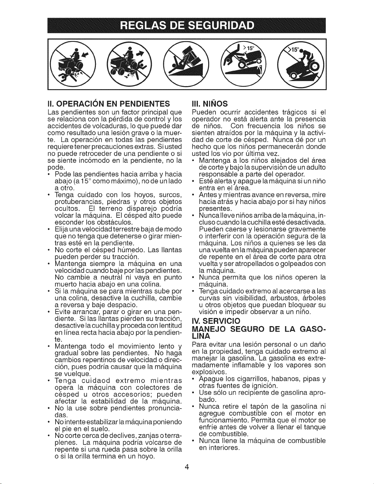
II. OPERACION EN PENDIENTES
Las pendientes son un factor principal que
se relaciona con la perdida de control y los
accidentes de volcaduras, Io que puede dar
como resultado una lesi6n grave o la muer-
te. La operaci6n en todas las pendientes
requiere tener precauciones extras. Si usted
no puede retroceder de una pendiente o si
se siente inc6modo en la pendiente, no la
pode.
• Pode las pendientes hacia arriba y hacia
abajo (a 15 ° como maximo), no de un lado
a otro.
• Tenga cuidado con los hoyos, surcos,
protuberancias, piedras y otros objetos
ocultos. El terreno disparejo podria
volcar la ma.quina. El cesped alto puede
esconder los obstaculos.
• Elija unavelocidad terrestre baja de modo
que no tenga que detenerse o girar mien-
tras este en la pendiente.
• No corte el cesped hOmedo. Las Ilantas
pueden perder su tracci6n.
• Mantenga siempre la m_tquina en una
velocidad cuando baje por las pendientes.
No cambie a neutral ni vaya en punto
muerto hacia abajo en una colina.
• Si la maquina se para mientras sube pot
una colina, desactive la cuchilla, cambie
a reversa y baje despacio.
• Evite arrancar, parar o girar en una pen-
diente. Si las !lantas pierden su tracci6n,
desactive la cuchilla y proceda con lentitud
en linea recta hacia abajo por la pendien-
te.
• Mantenga todo el movimiento lento y
gradual sobre las pendientes. No haga
cambios repentinos de velocidad o direc-
ci6n, pues podria causar que la maquina
se vuelque.
• Tenga cuidaod extremo mientras
opera la m_.quina con colectores de
cesped u otros accesorios; pueden
afectar la estabilidad de la maquina.
• No la use sobre pendientes pronuncia-
das.
• No intente estabilizar la maquina poniendo
el pie en el suelo.
• No corte cerca de declives, zanjas oterra-
plenes. La m_.quina podria volcarse de
repente si una rueda pasa sobre la orilla
o si la orilla termina en un hoyo.
Iii. NINOS
Pueden ocurrir accidentes tr_.gicos si el
operador no esta alerta ante la presencia
de nihos. Con frecuencia los nihos se
sienten atraidos por la maquina y la activi-
dad de corte de cesped. Nunca de por un
hecho que los nitros permaneceran donde
usted los vio por 61tima vez.
• Mantenga a los nihos alejados del _trea
de corte y bajo la supervisi6n de un adulto
responsable a parte del operador.
• Estealertayapague lam_tquinasi un niho
entra en el area.
• Antes y mientras avance en reversa, mire
hacia atr_.s y hacia abajo por si hay nitros
presentes.
• Nunca Ileve nihos arriba de la m_tquina, in-
cluso cuando la cuchilla este desactivada.
Pueden caerse y lesionarse gravemente
o interferir con la operaci6n segura de la
m_.quina. Los nihos a quienes se les da
unavuelta en la m#.quina pueden aparecer
de repente en el _.rea de corte para otra
vuelta y ser atropellados o golpeados con
la m_.quina.
• Nunca permita que los nitros operen la
maquina.
• Tenga cuidado extremo al acercarse alas
curvas sin visibilidad, arbustos, arboles
u otros objetos que puedan bloquear su
visi6n e impedir observar a un nitro.
IV. SERVlClO
MANEJO SEGURO DE LA GASO-
LINA
Para evitar una lesi6n personal o un dar_o
en la propiedad, tenga cuidado extremo al
manejar la gasolina. La gasolina es extre-
madamente inflamable y los vapores son
exp!osivos.
• Apague los cigarrillos, habanos, pipas y
otras fuentes de ignici6n.
• Use s61o un recipiente de gasolina apro-
bado.
• Nunca retire el tap6n de la gasolina ni
agregue combustible con el motor en
funcionamiento. Permita que el motor se
enfr[e antes de volver a Ilenar el tanque
de combustible.
• Nunca Ilene la maquina de combustible
en interiores.
4
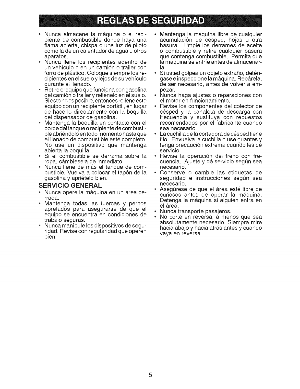
• Nunca almacene la m&quina o el reci-
piente de combustible donde haya una
flama abierta, chispa o una luz de piloto
como la de un calentador de agua u otros
aparatos.
• Nunca Ilene los recipientes adentro de
un vehiculo o en un cami6n o trailer con
forro de pl&stico. Coloque siempre los re-
cipientes en el suelo y lejos de su vehiculo
durante el Ilenado.
• Retire el equipo quefunciona con gasolina
del cami6n o trailer y rellenelo en el suelo.
Si esto no es posible, entonces rellene este
equipo con un recipiente port&til, en lugar
de hacerlo directamente con la boquilla
del dispensador de gasolina.
• Mantenga la boquilla en contacto con el
borde deltanque o recipiente de combusti-
ble abriendolo en todo momento hasta que
el Ilenado de combustible este completo.
No use un dispositivo que mantenga
abierta la boquilla.
• Si el combustible se derrama sobre la
ropa, c&mbiesela de inmediato.
• Nunca Ilene de m&s el tanque de com-
bustible. Vuelva a colocar el tap6n de la
gasolina y aprietelo bien.
SERVIClO GENERAL
• Nunca opere la m&quina en un &rea ce-
rrada.
• Mantenga todas las tuercas y pernos
apretados para asegurarse de que el
equipo se encuentra en condiciones de
trabajo seguras.
• Nunca manipule los dispositivos de segu-
ridad. Revise con regularidad que operen
bien.
• Mantenga la m&quina libre de cualquier
acumulaci6n de cesped, hojas u otra
basura. Limpie los derrames de aceite
o combustible y retire cualquier basura
que contenga combustible. Permita que
la m&quina se enfrie antes de almacenar-
la.
• Si usted golpea un objeto extraho, deten-
gase e inspeccione la m&quina. Rep&rela,
de ser necesario, antes de volver a em-
pezar.
• Nunca haga ajustes o reparaciones con
el motor en funcionamiento.
• Revise los componentes del colector de
cesped y la canaleta de descarga con
frecuencia y sustituya con repuestos
recomendados pot el fabricante cuando
sea necesario.
• La cuchilla de la cortadora de cesped tiene
filo. Envuelva la cuchilla o use guantes y
tenga precauci6n extrema cuando les de
servicio.
• Revise la operaci6n de! freno con fie-
cuencia. Ajuste y de servicio segQn sea
necesario.
• Conserve o cambie las etique,tas de
seguridad e instrucciones segun sea
necesario.
• AsegQrese de que el _.rea este libre de
curiosos antes de operar la m_tquina.
Detenga la maquina si alguien entra en
el area.
• Nuncatransporte pasajeros.
• No corte en reversa, a menos que sea
absolutamente necesario. Siempre mire
hacia abajo y hacia atras antes y cuando
vaya en reversa.
5

Capacidad de 1.2 cuartos
gasolina y Tipo: Regular sin plomo
Tipo de aceite SAE 30 (por encima
API-SG-SL): de los 32°F 6 0°C)
SAE 5W-30 (por debajo
de los 32°F 6 0°C)
Capacidad deaceite: 20 onzas
Bujia: Champion RC12YC
(Espacio: .030")
Velocidad terrestre
Hacia adelante: 0-4 mph (0-6.5 kph)
Reversa: 0-1 mph (0-1.6 kph)
Torque del perno 45 - 55 pies/Libras).
de la cuchilla:
RESPONSABILIDADES DEL
CLIENTE
• Lea y observe las reglas de seguridad.
• Siga un programa regular al darle mante-
nimiento, cuidados y uso a su cortadora
de cesped.
• Siga las instrucciones de las secciones
de "Mantenimiento" y '_Jmacenamiento"
de este manual del propietado.
_DVERTENClA: Esta cortadora de
cesped est& equipada con un motor de
combusti6n interna y no se debe usar en
o cerca de terrenos cubiertos de bosques
sin mejoras, cubiertos de arbustos o cu-
biertos de pastos, a menos que el sistema
de escape del motor este equipado con un
parachispas que cumpla con las leyes loca-
les o estatales aplicables (de haberlas). Si
se usa un parachispas, el operador deber&
darle mantenimiento en un orden de trabajo
efectivo.
En e! estado de California, las leyes exigen
el uso de un parachispas (Secci6n 4442 del
C6digo de Recursos POblicos de California).
Otros estados pueden tener leyes similares.
En los terrenos federales se aplican las leyes
federales. Se puede obtener un parachispas
para el silenciador a traves del centro de
servicio autorizado m&s cercano.
lnserto del volante
(1) Pasador
Cubierta de direcci6n
Asiento
(1) Arandeta ptana grande
@
Votante
(1) Arandeta ptana 5/16 (1) Contratuerca 5/16-18
Adaptador det votante
(1) Arandeta
(1) Perilta
(1) Contratuerca 1/2-20
@
(1) Perno hexagonal
5/16-18 x 1 1/2
(2) Ltave
6
Cubierta del
eje de direcci6n
Eje de
direcci6n
Hoja de inctinaci6n
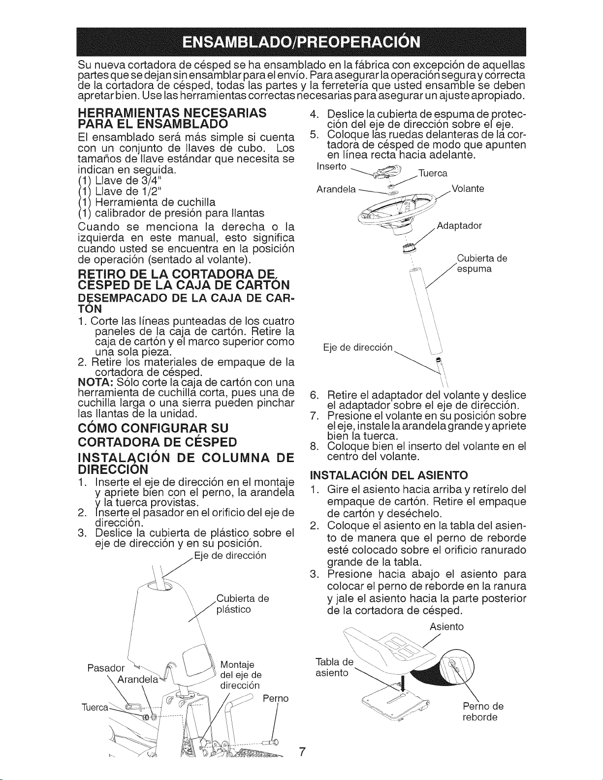
Su nueva cortadora de cesped se ha ensamblado en la f_.bfica con excepci6n de aquellas
partes que se dejan sin ensamblar para e! env[o. Para asegurar la operaci6n seguray correcta
de la cortadora de cesped, todas las partes y la ferreteria que usted ensamble se deben
apretar bien. Use las herramientas correctas necesarias para asegurar un ajuste apropiado.
HERRAMIENTAS NECESARIAS
PARA EL ENSAMBLADO
El ensamblado ser& m&s simple si cuenta
con un conjunto de Naves de cubo. Los
tamar_os de Ilave est&ndar que necesita se
4. Deslice la cubierta de espuma de protec-
ci6n del eje de direcci6n sobre el eje.
5. Coloque las ruedas delanteras de la cor-
tadora de cesped de modo que apunten
en Ifnea recta hacia adelante.
indican en seguida.
(1) Llave de 3/4"
(1) Llave de 1/2"
Inserto "--'--_,__Tu erca
Arandela -___ Volante
(1) Herramienta de cuchila
(1) calibrador de presi6n para Nantas
Cuando se menciona la derecha o la
izquierda en este manual, esto significa
_'-- _-_'_ Adaptador
cuando usted se encuentra en la posici6n
de operaci6n (sentado al volante).
RETIRO DE LA CORTADORA DE.
Cubierta de
3uma
CESPED DE LA CAJA DE CARTON
DESEMPACADO DE LA CAJA DE CAR-
TON
1. Corte las Ifneas punteadas de los cuatro
paneles de la caja de cart6n. Retire la
caja de cart6n y el marco superior como
una sola pieza.
2. Retire los materiales de empaque de la
cortadora de cesped.
NOTA: S61o corte la caja de cart6n con una
herramienta de cuchilla corta, pues una de
cuchilla larga o una sierra pueden pinchar
las Nantas de la unidad.
COMO CONFIGURAR SU
CORTADORA DE ClaSPED
INSTALACION DE COLUMNA DE
DIRECCION
1. Inserte el eje de direcci6n en el montaje
y apriete bJen con el perno, la arandela
y la tuerca provistas.
2. Inserte el pasador en el orificio del eje de
direcci6n.
3. Deslice la cubierta de pl_.stico sobre el
eje de direcci6n yen su posici6n.
Eje de direcci6n
_\ Cubierta
plfistico de
\
\
\
Pasador
Montaje
del eje de
direcci6n
Perno
.......... 4- S:LI
Eje de direcci6n .... ....
6. Retire el adaptador del volante y deslice
el adaptador sobre el eje de direcci6n.
7. Presione e! volante en su posici6n sobre
el eje, instale la arandela grande y apriete
bien la tuerca.
8. Coloque bien el inserto del volante en el
centro del volante.
INSTALACION DEL ASIENTO
1. Gire el asiento hacia arriba y retrelo del
empaque de cart6n. Retire el empaque
de cart6n y desechelo.
2. Coloque el asiento en la tabla del asien-
to de manera que e! perno de reborde
este colocado sobre el orificio ranurado
grande de la tabla.
3. Presione hacia abajo el asiento para
colocar el perno de reborde en la ranura
y jale el asiento hacia la parte posterior
de la cortadora de cesped.
Asiento
\\
Tabla de_
asiento
Perno de
reborde
7

4. Gire el asiento y latabla hacia adelante y
ensamble la perilla de ajuste y la arandela
plana sin apretar. No apriete.
Arandela plana
Perilla ajuste
5. Baje el asiento a la posici6n de operaci6n
sientese sobre el.
6. Deslice el asiento hasta que Iogre una
posici6n c6moda, Io que le permitir&
presionar el pedal del embrague/freno
hasta el fondo.
7. Retirese del asiento sin mover su posici6n
ajustada.
8. Eleve el asiento y apriete bien la perilla
de ajuste.
REVISE LA BATERiA
AsegOrese de que la bateria este bien
sujetada, y que todos los cables esten
bien conectados.
• La baterfa est& ubicada debajo del
asiento.
• La bateria se ha cargado por completo
en la f&brica antes de su instalaci6n.
Asiento
Bateria
NOTA: Ahora puede sacar la cortadora de
cesped de la tarima. Observe las siguientes
instrucciones apropiadas para retirar la
cortadora de cesped de la tarima.
_IbADVERTENClA: Antes de empezar, lea,
entienda y siga todas las instrucciones de
la secci6n de Operaci6n de este manual.
AsegOrese de que la cortadora de cesped
este en un &rea bien ventilada. AsegOrese
de que el &rea de enfrente de la cortadora
de cesped este libre de gente y objetos.
PARA SACAR LA CORTADORA DE
ClaSPED DE LA TARIMA (Consulte
la secci6n de Operaci6n para vet la
ubicaci6n y funci6n de los controles)
1. Eleve la palanca de! elevador de la
plataforma hasta su posici6n m&xima.
2. Suelte el freno de estacionamiento al
liberar el pedal del embrague/freno.
3. Active el control de la rueda libre. Con-
suite la parte de "TRANSPORTE" en la
secci6n de Operaci6n de este manual.
4. Saque la cortadora de cesped de la
tarima.
REVISE LA PRESION DE LAS
LLANTAS
Las Ilantas de la cortadora de cesped
se inflaron de m&s en la f&brica para su
transporte. Corregir la presi6n de las Ilan-
tas es importante para obtener el mejor
desempeho del corte.
• Reduzca la presi6n de las Ilantas a la
PSI que se muestra en las Ilantas.
REVISE LA NIVELACION DE LA
PLATAFORMA
Para obtener los mejores resultados de
corte, la carcasa de la cortadora de cesped
se debe niv,elar bien. Consulte la parte de
"NIVELACION DE L,A CARCASA DE LA
CORTADORA DE CESPED" en la secci6n
de Servicio y Ajustes de este manual.
REVISE LA POSICKSN CORRECTA
DE LA ClNTA DEL IMPULSOR DE
LA CORTADORA DE ClaSPED
Observe la figura que se muestra para
cambiar la cinta del impulsor de la corta-
dora de cesped en la secci6n de servicio
y ajuste de este manual. Verifique que la
cinta este en la ruta correcta.
REVISE EL SISTEMA DE FRENO
Despues de que haya aprendido c6mo
operar su cortadora de cesped, revise que
el freno funcione bien. Consulte la parte
de 'AJUSTE DE FRENO" en la secci6n de
Servicio y Ajustes de este manual.
8

_fLISTA DE COMPROBACION
Antes de operar su nueva cortadora de ces-
ped, deseamos asegurarnos de que usted
obtenga el mejor desempefio y satisfacci6n
de este Producto de Calidad.
Por favor revise la siguiente lista de com-
probaci6n:
_/" Todas las instrucciones de ensamblaje
se han completado.
_/" No queda ninguna parte suelta en la caja
de cart6n.
_/" La bateria esta bien conectada.
_/" El asiento est& ajustado c6modamente
y bien apretado.
_/" Todas las Ilantas est_.n bien infladas. (Las
Ilantas se inflan de m&s en la f&brica para
su transportaci6n).
_/" AsegQrese de que la plataforma de la
cortadora de cesped este bien nivelada
de lado a lado y de! frente a la parte pos-
terior para obtener los mejores resultados
de corte. (Las Ilantas deben estar bien
infladas para la nivelaci6n).
_/" Revise la cinta de la cortadora de cesped.
AsegQrese de que este en la ruta correcta
alrededor de las poleas y adentro de
todas las sujeciones de la cinta.
Vf Revise e! cableado. AsegOrese de que to-
das las conexiones esten bien colocadas
y que los cables esten bien sujetos.
_/" Antes de conducir la cortadora de cesped,
asegOrese de que el control de la rueda
libre este en la posici6n de "transmisi6n
activada" (consulte la parte de "TRANS-
PORTE" en la secci6n de Operaci6n de
este manual).
AI aprender c6mo usar su cortadora de ces-
ped, preste atenci6n extra a los siguientes
puntos importantes:
_/" El aceite del motor est& en un nivel ade-
cuado.
_/" El tanque de combustible est,. lleno
con gasolina sin plomo regular nueva y
limpia.
_/" Familiaricese con todos los controles, su
ubicaci6n y funci6n. Operelos antes de
arrancar el motor.
_/" AsegOrese de que el sistema de freno est&
en condiciones de operaci6n seguras.
V" Es importante purgar latransmisi6n antes
de operar su tractor por la primera vez.
Siga las instrucciones adecuadas para
el empiezo y para purgar (Vea "PARA
EMPEZAR EL MOTOR" y "PARA PUR-
GAR LA TRANSMISl0N" en la secci6n
de la Operaci6n de este manual).
9

Estos simbolos pueden aparecer en la cortadora de cesped o en la literatura provista
con el producto. Aprenda y entienda su significado.
R N H L I',,I ¢
MARCHA ATR,_,S NEUTRO ALTO BAJO ESTRANGU- R_,PI DO LENTO
LACION
INTERRUPTOR
DE IGNICION
45 o;; ® 0
MOTOR SlSTEMA MOTOR
APAGADO FUNCIONAMIENTO ENCENDIDO
ATRAS (ROS)
MOTOR PRESION FRENO DE FRENO DE
EN MARCHA DEL ACEITE MANO SE CERRO MANO ABIERTO
t
SOBRE LUZ DE COMBUSTIBLE PRESION
TEMPERATURAS DEL ACEITE
ACCESORIO DEL ACCESORIO DEL
EMBRAGUE EMBRAGUE
ENGANCHADO DESENGANCHADO
CONTROLDE
RUEDALIBRE
DESACTIVADO
PEDAL DE
FRENO/EMBRAGUE
CONTROL DE
ACTIVADO
RUEDALIBRE &
No seguir las siguientes instrucciones
puede provocar heridas o muerte. Los
sl'mbolos de aviso de seguridadse utilizan
para identificar informaciones de seguridad
relativas a peligros que puedenprovocar la
muerte, heridas graves yio dafios a la
maquina.
BATER[A MARCHA
PELIGRO, GUARDE LAS
MANOSY LOS PIES LEJOS
,3hl{ll_l£11_.,
ATR4,S
PELIGRO indica un peligro que, si no se evita,
provoca muerte o lesiones graves.
ADVERTENClA indica un peligro que, si no se evita,
puede provocar muerte o lesiones graves.
PRECAUCION indica un peligro que, si no se evita,
puede provocar lesiones ligeras o moderadas.
PRECAUClON cuando se utiliza sin el s_mbolo de
aviso, indica una situaci6n que puede provocar
dafios al tractor y/o al motor.
SUPERFiCiES CALIENTES indica un peligro que,
si no se evita, puede provocar la muerte, lesiones
graves y/o danos a la maquina.
FUEGO indica un peligro que, si no se evita, puede
provocar la muerte, lesiones graves y/o danos
a la maquina.
MARCHA ALTURA DE LA LEVANTAMIENTO
HACIA ADELANTE SEGADORA DE LA SEGADORA
®@®@@
MANTENGA EL PELIGROS DE
AREA DESPEJADA PENDIENTES
(Vea la secci6n de lasreglasde seguridad)
10

CONOZCA SU CORTADORA DE CESPED
LEA ESTE MANUAL DEL PROPIETARIO Y LAS REGLAS DE SEGURIDAD ANTES
DE OPERAR SU CORTADORA DE CESPED
Compare las ilustraciones con su cortadora de cesped para familiarizarse con las ubicacio-
nes de los diferentes controles y ajustes. Conserve este manual para futuras consultas.
Pedal del freno " ---" estacionamiento
Palanca del
embrague de la
plataforma
lembolo de la Interruptor de
palanca del arranque
elevador Palanca de
Palanca de de
ajuste de movimiento
altura
Control de rueda
libre
_, _ .....; ,_../ /_ Pedal del freno de
(ROS) en
posici6n "on"
Nuestra cortadora de cesped cumple con las normas de seguridad aplicables del
Instituto Nacional Estadounidense de Normas.
PALACA DEL EMBRAGUE DE LA
PLATAFORMA - Se usa para activar la
cuchilla de la cortadora de cesped.
PEDAL DEL FRENO- Se usa para frenar
la cortadora de cesped y arrancar el
motor.
PALANCA DE AJUSTE DE ALTURA - Se
usa para ajustar la altura de corte de la
cortadora de cesped.
INTERRUPTOR DE ARRANQUE - Se
usa para arrancar y detener e! motor,
I_MBOLO DE LA PALANCA DEL ELE-
VADOR - Se usa para soltar la palanca
de ajuste de altura cuando se cambia su
posici6n.
PALANCA DE FRENO DE ESTAClONA-
MIENTO - Fija el freno de estacionamien-
to en la posici6n de freno.
PALANCA DE CONTROL DE MOVl-
MIENTO - Selecciona la velocidad y
direcci6n de la cortadora de cesped.
CONTROL DE RUEDA LIBRE - Desacti-
va la transmisi6n para empujar o remolcar
despacio la cortadora de cesped con el
motor apagado.
INTERRUPTOR DEL SISTEMA DE FUNClO-
NAMIENTO HAClA ATRAS (ROS) EN POSI=
ClON "ON" = Permite la operaci6n del conjunto
segador o otro accesorio accionado mientras
queen reves.
11

La operaci6n de cualquier cortadora de cesped puede causar que entren
SEGURIDAD
objetos extrahos en los ojos, !o que puede provocar un daho severo en los
mismos. Use siempre lentes de seguridad o protecciones oculares mien-
tras este operando la cortadora de cesped o realizando cualquier ajuste o
reparaci6n. Se recomienda usar una careta de seguridad de visi6n amplia
sobre los anteoos o lentes de se uridad estandar.
COMO USAR LA CORTADORA DE
CESPED
ACTIVACION DEL FRENO DE ESTA=
CIONAMIENTO
La cortadora de cesped est,. equipada con
un interruptor de detecci6n de presencia de!
operador. Cuando el motor este en funcio-
namiento, cualquier intento del operador de
dejar el asiento sin primero activar el freno
de estacionamiento apagar& el motor.
1. Presione el pedal del freno completa-
mente hasta abajo y mantengalo pre-
sionado.
2. Suelte la palanca del freno de estaciona-
miento y libere la presi6n del pedal del
freno. El pedal debe permanecer en la
posici6n de freno. AsegOrese de que
el freno de estacionamiento mantendra
detenida la cortadora de cesped.
Presione el pedal Palanca de
del freno de control de Ajuste de
estacionamiento _ovimiento cortadoraalturadedela
para "activar" , cesped
Posici6n de
"desactivada" de
la palanca del
"activado" embrague de la
del pedal del plataforma
freno Posici6n del Posici6n de "activada"
"impulsor" de la palanca del
del pedal del embrague de la
freno plataforma
PARADA
CUCHILLA DE LA CORTADORA DE
CESPED -
• Para detener la cuchilla de la cortadora de
cesped, mueva la palanca del embrague
de la plataforma a la posici6n de desac-
tivada".
MECANISMO DE DESPLAZAMIENTO -
• Paradetener el mecanismo de desplazamien-
to, suelte el pedal del freno pot completo.
MOTOR -
• Gire la Ilave de arranque a la posici6n
PARAD,_' y saque la Ilave. Retire siempre
la Ilace cuando se aleje de la cortadora de
cesped para evitar su uso no autorizado.
IMPORTANTE: Dejar el interruptor de
arranque en una posici6n que no sea la
de "PARAD,_' causar& que la baterfa se
descargue y quede muerta.
NOTA: Bajo ciertas condiciones, cuando
la cortadora de cesped est,. parada con el
motor funcionando, los gases de escape
del motor caliente pueden causar que el
cesped se "tome marr6n". Para evitar
esta posibilidad, detenga siempre el motor
cuando pare la cortadora de cesped sobre
,_as con cesped.
PRECAUCION: Detenga siempre la
cortadora de cesped por completo, conforme
se describe arriba, antes de dejar la posici6n
del operador.
IVIOVlMIENTO HAClA ADELANTE Y
HAClA ATRAS
La direcci6n y lavelocidad de! movimiento se
controla por medio de la palanca de control
de movimiento.
1. Comience a conducir la cortadora de
cesped con el pedal del embrague/freno
presionado y la palanca de control de
movimiento en la posici6n neutral (N).
2. Mueva la palanca de control de movi-
miento a la posici6n deseada.
3. Suelte despacio el pedal del embrague/
freno para comenzar a moverse.
IMPORTANTE: Pare por completo la cor-
tadora de cesped antes de girar o cambiar
de velocidad. No hacerlo reducir& la vida
Otil del transeje.
AJUSTE DE LA ALTURA DE CORTE DE
LA CORTADORA DE CESPED
La posici6n de la palanca del elevador de
la plataforma de la cortadora de cesped
determina la altura de corte.
• Agarre la palanca del elevador.
• Presione el embolo de la palanca del ele-
vador con el pulgar y mueva la palanca a
la posici6n deseada.
El rango de altura de corte es de aproxima-
damente 1-1/2 a 4". Las alturas se miden
desde el suelo hasta la punta de la cuchilla
con el motor sin funcionar. Estas alturas
son aproximadas y pueden variar segOn las
condiciones del suelo, la altura del cesped y
los tipos de cespedes que se van a cortar.
• El cesped promedio se debe cortar aproxi-
madamente a 2 1/2" (6.35 cm) durante
la temporada fria y a m&s de 3" (7 cm)
durante los meses de calor. Para que el
cesped crezca m&s sano y tenga mejor
aspecto, c6rtelo con frecuencia y despues
de un crecimiento moderado.
12

• Para un mejor rendimiento del corte, el
cesped de m&s de 6" (15.20 cm) de altura
debe cortar dos veces. Haga el primer
corte relativamente alto; el segundo de-
ber& ser a la altura deseada.
OPERAClON DE LA CORTADORA DE
CESPED
La cortadora de cesped est& equipada con
un interruptor de detecci6n de presencia de!
operador. Cualquier intento del operador
de dejar el asiento con el motor en funcio-
namiento y el embrague de la plataforma
activado apagar& el motor. Usted debe
permanecer colocado por completo en el
centro del asiento para evitar que e! motor
se desoriente o se apague cuando opere el
equipo sobre un terreno Ileno de baches u
ondulante o en colinas.
1. Seleccione la altura de corte deseada.
2. Active la cuchilla de la cortadora de
cesped al accionar la palanca del
embrague de la plataforma.
PARA DETENER LA, CUCHILLA DE LA
CORTADORA DE CESPED-
Desactive la palanca del embrague de la
plataforma.
Posici6n de "desactivada" Posici6n alta de
de la palanca del ajuste de altura
embrague de la plataforma de la cortadora
de cesped
FUNClONAMIENTO ATRAS
Tu tractor est& equipado con el Sistema
de Funcionamiento Atr&s (ROS). Cual-
quier tentativa del operador de viajar
marcha atr&s con el embrague puesto
apagar& el motor a menos que la Ilave de
ignici6n se ponga en la posici6n de "ON"
del ROS.
ATENClON: Ir marcha atr&s con e! em-
brague puesto para cortar, no es reco-
mendable. Poniendo e! ROS en posici6n
"ON", para permitir el funcionamiento
atr&s con el embrague puesto, se tiene
que hacer s61o cuando el operador Io
considera necesario para reposicionar la
m&quina con e! dispositivo embragado.
No siegue en reves a rnenos que sea
absolutamente necesario.
USAR EL SISTEMA DE FUNCIONA-
MIENTO ATRAS -
Utilice el tractor solamente si est& seguro
de que no ingresar&n nitros ni otras per-
sonas o animales al &rea donde se va a
cortar el cesped.
1. Mover la palanca de mando del movi-
miento en la posici6n neutro (N).
2. Con el motor en marcha, girar la Ilave
del interruptor de la ignici6n en el sen-
tido inverso al de las agujas del reloj
hasta la posici6n "ON".
3. Mire hacia abajo y hacia atr&s no s61o
antes de ir marcha atr&s, sino mientras
este yendo marcha atr&s.
4. Mover despacio la palanca de mando
del movimiento hacia la posici6n atr&s
(R) para empezar el movimiento.
5. Cuando el uso del ROSes m&s nec-
esario, de vuelta a la Ilave de ignici6n
en el sentido de las agujas del reloj
hasta la posici6n "ON".
Posici6n baja de
Posici6n de "activada" de ajuste de altura
la palanca del embrague de la cortadora de
de la plataforma cesped
PRECAUOION: No opere la cortadora
de cesped sin el colector de cesped entero,
en las cortadoras de cesped equipadas con
este, o sin la coraza del deflector en su sitio.
Coraza del deflector 13
Posici6n ROS "ON" Motor en posici6n "ON"

OPERACION EN COLiNAS
_, ADVERTENClA: No conduzca hacia
arriba o hacia abajo en colinas con pen-
dientes mayores de 15 ° y no conduzca de
un lado a otro en ninguna pendiente. Use
la guia de pendientes de la parte posterior
de este manual.
• Elija la velocidad m_.s lenta antes de
comenzar a bajar o subir colinas.
• Evite detenerse o cambiar de velocidad
en las colinas.
• Si es absolutamente necesario detenerse,
empuje con rapidez el pedal de! embrague/
freno a la posici6n de freno y active el
freno de estacionamiento.
• Mueva la palanca de control de movi-
miento a la posici6n neutral (N).
• Para reiniciarel movimiento, suelte despa-
cio e! freno de estacionamiento y el pedal
del embrague/freno.
• De todas las vueltas despacio.
TRANSPORTE
AI empujar o remolcar la cortadora de cesped,
asegQrese de desactivar la transmisi6n al
colocar el control de la rueda libre en la
posici6n de rueda libre. El control de rueda
libre se ubica en la barra de tracci6n posterior
de la cortadora de cesped.
• Eleve el ajuste de altura de la cortadora
de cesped a su posici6n m_.s alta con la
palanca de ajuste de altura de la corta-
dora de cesped.
2. Retire el tap6n/la varilla de Ilenado de
aceite y limpiela con un patio, reinserte
la varilla y atornille bien el tap6n, espere
unos cuantos segundos, retire!o y verifi-
que el nivel del aceite. Si es necesario,
agregue aceite hasta que llegue a la
marca que dice "LLENO" en la varilla.
No Io Ilene de m&s.
• Para operarla en clima frio, usted debe
cambiar el aceite para obtener un
arranque m&s f&cil (Consulte la tabla
de viscosidad de aceite de la secci6n
de Mantenimiento de este manual).
• Paracambiarelaceite del motor, consulte
la secci6n de Mantenimiento en este
manual.
COMO AGREGAR GASOLINA
• Llene el tanque de combustible hasta la
parte inferior del cuello de relleno. No Io
Ilene de m&s. Use gasolina sin plomo
regular nueva y limpia con un minimo de
87 octanos. (Usar gasolina con plomo
incrementar& los dep6sitos de carbono
y 6xido de plomo y reducir& la vida de la
v&lvula). No mezcle aceite con gasolina.
Compre combustible en cantidades que
se puedan usar en 30 dias para asegurar
la frescura del combustible.
_,PRECAUOI6N: Limpie cualquier derra-
me de aceite o combustible. No almacene,
derrame ni use gasolina cerca de una flama
abierta.
Control de
rueda libre
desactivado
Control de
rueda libre
activado
o
Empuje el control de rueda libre hacia
abajo con el pie.
o
Para reactivar la transmisi6n, realice al
reves el procedimiento anterior o presione
por completo la palanca del freno hacia
abajo.
ANTES DEL ARRANQUE DEL MOTOR
REVISE EL NIVEL DE ACEITE DEL
MOTOR
El motor de la cortadora de cesped se envia
desde la f&brica ya Ilena con aceite de peso
para el verano.
1. Revise el aceite del motorcon la cortadora
de cesped sobre un suelo nivelado.
_IbPRECAUClON: Los combustibles
mezclados con alcohol (llamados gasohol
o que usan etanol o metano!) pueden atraer
la humedad, Io que provoca la separaci6n
y formaci6n de &cidos durante el almace-
namiento. El gas _.cido puede dar_ar e!
sistema de combustible de un motor mientras
se encuentra en almacenamiento. Para
evitar problemas con el motor, el sistema
de combustible se debe vaciar antes del
almacemaniento durante 30 dias o m&s.
Drene el tanque de gasolina, arranque el
motor y h&galo funcionar hasta que las
lineas de combustible y el carburador esten
vacios. Use combustible nuevo en la pr6xima
temporada. Consulte las Instrucciones de
AImacenamiento para obtener informaci6n
adicional. Nunca use productos limpiadores
para motor o carburador en el tanque de
combustible porque puede ocurrir un daho
permanente.
14

ARRANQUE DEL MOTOR
Cuando arranque el motor por primera vez
o si al motor se le ha agotado el combus-
tible, se necesitara un tiempo de arranque
extra para que e! combustible se mueva
desde e! tanque hasta el motor.
1. AsegOrese de el control de la rueda
libre este en la posici6n de la transmi-
si6n activada.
2. Co!6quese en el asiento en la posici6n
de operaci6n, presione el pedal del
embrague/freno y active el freno de
estacionamiento.
3. Coloque la palanca de control de movi-
miento en la posici6n neutral (N).
Tapa del dep6sito
de gasolina
C ONSEJOS PARA CORTAR EL
CESPED
• La cortadora de cesped debe estar bien
nivelada para que su desempeho sea, e!
mejor. Consulte la parte de "NIVELACION
DE LA. CARCASA DE LA CORTADORA
DE CESPED" en la secci6n de Servicio
y Ajustes de este manual.
• El lado izquierdo de la cortadora de cesped
se debe usar para podar.
• Conduzca de manera que los recortes de
descarguen sobre el &rea que ya se ha
cortado. El &rea de corte debe estar del
lado derecho de la cortadora de cesped.
Esto crear& una distribuci6n m&s uniforme
de los recortes y un corte m&s uniforme.
• Cuando corte &teas grandes, comience
girando hacia la derecha, de modo que
los recortes se descarguen lejos de los
arbustos, bardas, caminos, etc. Despues
de una o dos vueltas, corte en la direcci6n
opuesta, dando vueltas hacia la izquierda
hasta que termine.
Manija de
arranque
manual
4. Mueva el embrague de la plataforma a
la posici6n de desactivado.
5. Inserte la Ilave en el arranque y girela
hacia la derecha a la posici6n de
arranque y suelte la Ilave en cuanto se
encienda e! motor. No active el arran-
cador en forma continua durante m&s
de quince segundos por minuto.
NOTA: NOTA: Si se encuentra a una alti-
tud superior (por encima de los 3,000 pies
6 914 metros) o a una temperatura fria
(por debajo de los 32°F 6 0°C), puede set
necesario ajustar la mezcla del combusti-
ble para obtener el mejor desemper_o.
SlSMTEMA DE ARRANQUE MANUAL
Esta unidad est,. equipada con un sistema
de arranque manual del motor. Si la
bateria est,. demasiado descargada como
para arrancar el motor.
1. Accione el freno de estacionamiento.
2. Gire la Ilave a la posici6n de encendido
(ON).
3. AsegOrese de que la unidad est& en
posici6n neutral.
4. Co!oque la plataforma en la posici6n
desactivada.
5. Jale la cuerda manual para arrancar el
motor.
• Si el cesped est& demasiado alto, se
deber& cortar dos veces para reducir la
carga y la posibilidad de un peligro de
incendio por los recortes secos. Haga el
primer corte relativamente alto; el segundo
deber& ser a la altura deseada.
• No corte el cesped cuando este hOmedo.
El cesped hOmedo taponar& la cortadora
de cesped y dejar& matas indeseables.
Permita que el cesped se seque antes
de podarlo.
• Regule la velocidad terrestre al seleccio-
nar un avance Io suficientemente lento
para ajustar el desempeho de corte de la
cortadora de cesped asi como la calidad
del corte deseada.
• Cuando utilice accesorios, seleccione
una ve!ocidad terrestre que se adapte al
terreno y obtenga el mejor desemper_o
del accesorio que este usando.
15

PROGRAMA DE ANTES DE CADA CADA CADA CADA CADA
m
c
O
A
D
O
R
A
D
E
0
E
S
D
_ Limpiar la filtro de aire
_ Inspeccionar el silenciador/parachispas
R Limpiar las aletas de enfriamiento del motor
1- Cambiar mdts a menudo cuando se opere bajo carga pesada o en ambientes con altas temperaturas
2- Dar servicio m_ts a menudo cuando se opere en condiciones sucias o polvorosas.
3- Carnbiar las cuchillas mas a menudo cuando se siegue en suelo arenoso,
MANTENIMIENTO CADA USO 8 25 50 100 TEMPORADA
Revisar ia operaci6n del freno
Revisar ia presi6n de las Ilantas I_
Revisar la presencia del operador y el
sistema ROS
Revisar que los broches no est6n sueltos
Revisar/cambiar la cuchiiia de ia cortadora
de cesped
Limpiar la bateria y las terminales
Lubricar los ejes y husos
Revisar el enfriamiento del transeje
Revisar ia niveiaci6n de la cortadora
de cesped
Revisar la cinta en V
Aceitar las cadenas del impulsor
Revisar el nivel del aceite del motor
Revisar el aceite del motor
Limpiar la pantalla de aire
Cambiar la bujia
Cambiar el cartucho de papel del filtro
de aire
HORAS HORAS HORAS HORAS
_3
_1,2
_2
_2
&LMACENAMIENTO
v'
v'
V'
_2
RECOMENDACIONES GENERALES
La garantia para esta cortadora de cesped
no ampara los articulos que se han sometido
al abuso o la negligencia del operador. Para
recibir el valor completo de la garantia, el
operador debe darle mantenimiento a la
cortadora de cesped conforme se indica
en este manual.
Ser& necesario hacer algunos ajustes en
forma peri6dica para mantener de manera
correcta la cortadora de cesped.
AI menos una vez cada temporada, revise si
usted debe hacer algOn ajuste conforme se
describe en la secci6n de Servicio y Ajustes
de este manual.
• AI menos una vez al argo usted deber&
cambiar la bujia, limpiar o cambiar el filtro
de aire y revisar si la cuchilla y la cinta
est&n desgastadas. Una nueva bujfa y
un nuevo filtro de aire aseguran la mezcla
adecuada de aire y combustible, Io que
ayuda a que el motor funcione mejor y
dure m&s tiempo.
ANTES DE CADA USO
1. Revise el nivel del aceite del motor.
2. Revise la operaci6n del freno.
3. Revise la presi6n de las Ilantas.
4. Revise que los sistemas de presencia
del operador y de ROS funcionen bien.
5. Revise que los broches no esten sueltos.
JMPORTANTE: No aceite ni engrase los
puntos de los pivotes que tienen cojinetes
de nailon especiales. Los lubricantes vis-
cosos atraer&n el polvo y la suciedad, Io
que reducir& la vida de los cojinetes autolu-
bricantes. Si siente que se deben lubricar,
use s6lo un lubricante tipo grafito en polvo
moderadamente.
16

CORTADORA DE CO:SPED
Siga siempre las reglas de seguridad cuando
realice cualquier mantenimiento.
OPERACK)N DEL FRENO
Si la cortadora de cesped requiere m&s
de cuatro (4) pies (1.219 metros) para
detenerse a la ve!ocidad m&xima sobre una
superficie de concreto o pavimento seco
nivelado, entonces se debe dar servicio al
freno. (Consulte la parte de 'AJUSTE DEL
FRENO" en la secci6n de Servicio y Ajustes
de este manual).
LLANTAS
• Mantenga la presi6n de aire correcta en
todas las Ilantas (Consulte la PSI para las
Ilantas).
• Mantenga las Ilantas libres de gasolina,
aceite o quimicos para el control de
insectos, pues pueden dahar el caucho.
• Evite los palos, las piedras, los surcos
profundos, objetos filosos y otros peligros
que pueden causar daho en las Ilantas.
NOTA: Para sellar las pinchaduras de las
Ilantas y prevenir las Ilantas desinfladas
debido a fugas lentas, puede comprar
sellador de Ilantas con el distribuidor de
partes local. El sellador de Ilantas tambien
previene la podredura en seco y la corrosi6n
de las Ilantas.
EJE Y HUSOS
• Los ejes de las ruedas frontales y los
husos frontales se deben lubricar bien.
• Los ejes de las ruedas se deben lubricar
con un lubricante tipo grafito en polvo seco.
• Los husos se deben lubricar con un
lubricante a base de silicona tipo
aerosol.
Husos
El motor no arrancar& si el pedal de
embrague/freno esta completamente
presionado y e! mando del embrague del
accesorio esta desconectado.
VleRIFIF:Z SISTEMA PRESENCIA OPERADOR
Cuando el motor esta en marcha, cualquier
tentativa del operador de abandonar
el asiento sin haber puesto el freno de
estacionamiento primero, apagar& el
motor.
Cuando el motor est& en marcha y e!
embrague del accesono est& conectado,
cualquier tentativa del operador de
abandonar el asiento, apagar& e! motor.
El embrague del accesorio no tendria que
funcionar nunca si el operador no est& en
su asiento.
VleRIFI#:Z SlSTEMA FUNCIONAMIENTO
ATR#,S (ROS)
Cuando el motor est& en marcha con
el interruptor de Ilave en posici6n de
motor "ON" y el embrague del accesorio
conectado, cualquier tentativa del
operador de viajar marcha atr&s, apagar&
el motor.
Cuando el motor est& en marcha con
el interruptor de Ilave del sistema
de funcionamiento atr&s (ROS) en
la posici6n "ON" y el embrague del
accesorio conectado, cualquier tentativa
del operador de viajar marcha atr&s, NO
apagar& e! motor.
CUIDADO DE LA CUCHILLA
Para obtener los mejores resultados, la
cuchilla de la cortadora de cesped debe
estar afilada. Cambie la cuchilla si est&
desgastada, doblada o dahada.
_IPRECAUCl6N: Use s61o una cuchilla de
reemplazo aprobada por el fabricante de la
cortadora de cesped. Usar una cuchilla no
aprobada por el fabricante de la cortadora
de cesped es peligroso, pues podria dar_ar la
cortadora de cesped y anular la garant[a.
Posici6n ROS "ON"
Motor en posici6n "ON"
(Operaci6n Normal)
e de rueda
SISTEMA PRESENClA OPERADOR Y
SISTEMA FUNClONAMIENTO ATR._S (ROS)
Asegurarse de que el sistema de presen-
cia del operador, el sistema de trabajo y
el sistema funcionamiento atr&s funcionen
bien. Si tu tractor no funci6n como descri-
to, reparar el problema inmediatamente.
17

RETIRO DE LA CUCHJLLA
1. EJeve Ja cortadora de cesped a Ja po-
sici6n m&s alta para tener acceso a Ja
cuchilla.
NOTA: Protejase las manos con guantes
y/o envuelva la cuchilla con un patio grueso.
2. Retire el perno de la cuchilla gir&ndolo
hacia la izquierda.
3. Instale la nueva cuchilla con el disefio
que dice "ESTE LADO HACIA ARRI-
BA" hacia la plataforma y el ensambla-
je del mandril.
Mandril
Cuchilla
Perno de
cuchilla _-_ _...
(especial)
Estrella
Orificio central
IMPORTANTE: Para asegurar un en-
samblaje correcto, el orificio central de la
cuchilla se debe alinear con la estrella del
ensamblaje de! mandril.
4. Instale y ajuste bien el perno de la
cuchilla (45 - 55 pies/Libras).
IMPORTANTE: E! perno de la cuchilla
especial est& tratado con calor.
BATERiA
La cortadora de cesped tiene un sistema de
carga de la bateria que es suficiente para
el uso normal.
• Mantenga la batefia y los conectores
limpios.
• S61o recargue la bateria con un
cargador aprobado para una batefia de
2.8 amperes hora de 12V.
• Cargarla con cualquier otro cargador o con
un cargador tipo automotriz puede causar
un dafio permanente en la bateria.
• Cargue la batefia durante 24 horas para
que se cargue por completo.
NOTA: La bateria deJ equipo original de la
cortadora de cesped no necesita manteni-
miento. No intente abrir ni retirar los tapones
o las cubiertas. Agregar o revisar el nivel del
electrolito no es necesario.
_bADVERTENClA: No fuerce el arranque
de la bateria. Puede ocurrir un dafio perma-
nente en la bateria o una lesi6n personal.
ENFRIAMIENTO DEL TRANSEJE
Mantenga el transeje libre de cualquier acu-
mulaci6n de suciedad y paja, Io que puede
restringir el enfriamiento.
ClNTA EN V
Revise la cinta en V para ver si est,. dete-
riorada o desgastada despues de 100 horas
de operaci6n y c_.mbiela si es necesario.
La cinta no es ajustable. Cambie la cinta si
comienza a deslizarse por el desgaste.
MOTOR
LUBRICACKSN
Use s61o un aceite detergente de alta ca-
lidad calificado con la clasificaci6n SG-SL
de servicio de API. Seleccione el grado de
viscosidad SAE del aceite de acuerdo con la
temperatura de operaci6n esperada.
CALIDADES DE VISCOSIDAD DE SAE
F -20 0 30 32 40 60 80 100
c -do -2_ -lo ; 1'o do do 4o
GAMA DE TEMPERATURA ANTICIPADA ANTES DEL PROXIMO CAMBIO DE ACEITE
NOTA: Auque los aceites de viscosidad
mOitiple 5W30, 10W30, etc.) mejoran
el arranque en climas frios, los aceites
provocaran un incremento en el consumo
de aceite cuando se usan por encima de
los 32°F (0°C). Revise el nivel de aceite
del motor con m&s frecuencia para evitar
cualquier posibie dafio en el motor debido
a un nivel bajo de aceite.
Cambie el aceite despues de cada 25 horas
de operaci6n o al menos unavez al afio si no
se va a usar la cortadora de cesped durante
25 horas en un afio.
Revise el nivel de aceite del c&rter antes de
arrancar el motor y despues de cada ocho (8)
horas de operaci6n. Apriete bien e! tap6n/
la varilla de Ilenado del aceite cada vez que
revise el niveI deI aceite.
CAMBIO DE ACEITE DEL MOTOR
Determine el rango detemperatura esperado
antes de cambiar el aceite. Todo eI aceite
debe cumplir con la clasificaci6n SG-SL de
servicio de API.
• AsegOrese de que la cortadora de cesped
este sobre una superficie nivelada.
• El aceite se drenar& con mas libertad
cuando este tibio.
• El aceite se puede bombear desde el
motor con una bomba de sif6n mecanica
o electrica.
iap6n del
aceite
Llenado de
aceite
18
oilviscchartl s

1. Retire el tap6n/la varilla de Ilenado de!
aceite. Tenga cuidado de no permitir
que entre suciedad en el motor cuando
cambie el aceite.
2. Inserte el extremo de la bomba en el
recipiente del aceite.
3. Bombee el aceite del recipiente.
4. Rellene el motor con aceite a traves del
tubo de la varilla de Ilenado de aceite.
Vi@talo despacio. No Io Ilene de mas.
Para conocer la capacidad aproximada,
consulte la secci6n "ESPECIFICACIO-
NES DEL PRODUCTO" en este manual.
5. Use un calibrador en e! tap6n/varilla de
Ilenado de aceite para verificar el nivek
Para tener una lectura exacta, apriete
bien el tap6n de la varilla sobre el tubo
antes de retirar la varilla. Mantenga el
aceite en la linea que dice "LLENO" en
la varilla. Apriete bien el tap6n en el tubo
cuando termine.
FILTRO DE AIRE
El motor no funcionar& bien si se usa un
filtro de aire sucio. Cambie el filtro de aire
cada 100 horas de operaci6n o cada tem-
porada, Io que ocurra primero. De servicio
al limpiador de aire con mas frecuencia bajo
condiciones de polvo.
1. Retire la perilla de la cubierta y la cubier-
ta.
2. Retire con cuidado el cartucho.
3. Limpie con cuidado la base para evitar
que caiga basura en el carburador.
4. Paralimpiargolpeelo con gentileza sobre
una superficie plana.
/Perilla de cubierta
Filtro de aire
f-
5. Reinstale el cartucho y la cubierta, y
asegOrelos con la perilla de la cubierta.
NOTA: Si el cartucho esta muy sucio o
dar_ado, cambie!o.
IMPORTANTE: Los solventes de petr61eo,
como el queroseno, no se deben usar para
limpiar el cartucho. Pueden causar el de-
terioro del cartucho. No aceite el cartucho.
No use aire presurizado para limpiar el
cartucho.
LiMPIE LA PANTALLA DE AIRE
La pantalla de aire se debe mantener libre
de suciedad y paja para evitar que el motor
se dar_e por sobrecalentamiento. Limpie con
un cepillo de alambre o con aire comprimido
para retirar la suciedad y las fibras de goma
secas dificiles #e quitar.
LIMPIE LAS AREAS DE ENTRADA DE
AIRE/ENFRIAMIENTO
Para asegurar un enfriamiento adecuado,
cerci6rese de que la pantalla de cesped, las
aletas de enfriamiento y otras superficies
externas del motor se mantengan limpias
en todo momento.
Cada 100 horas de operaci6n (con mas fre-
cuencia bajo condiciones de polvo y suciedad
extremas), retire la carcasa del soplador
y otras cubiertas de enfriamiento. Limpie
las aletas de enfriamiento y las superficies
externas conforme sea necesario. AsegO-
rese de reinstalar de nuevo las cubiertas
de enfriamiento.
NOTA: La operaci6n del motor con la
pantalla de cesped b!oqueada, las aletas
de enfriamiento sucias o taponadas y/o las
cubiertas de enfriamiento sin colocar causara
daho por sobrecalentamiento.
SILENCIADOR
Inspeccione y cambie el silenciador y el
parachispas si tienen corrosi6n (si la unidad
esta equipada con estos) porque se podria
generar un peligro de incendio y/o dahos.
8UJIA(S)
Cambie la(s) bujia(s) al principio de cada
temporada o despues de cada 100 horas de
operaci6n, Io que ocurra primero. El tipo de
bujia y la configuraci6n del espacio se mues-
tran en la secci6n "ESPECIFICACIONES
DEL PRODUCTO" de este manual.
UMPIEZA
• Limpie cualquier materia extraha del motor,
la bateria, el asiento, el acabado, etc.
• Mantenga las superficies con acabado y
las Ilantas libres de cualquier residuo de
gasolina, aceite, etc.
• Proteja las superficies pintadas con cera
tipo automotriz.
No se recomienda usar una manguera para
jardin ni una lavadora a presi6n para limpiar
la cortadora de cesped, a menos que el
motor y la transmisi6n esten cubiertos para
protegerlos del agua. Si entra agua en el
motor o la transmisi6n se reducir& la vida
Otil de la cortadora de cesped. Use aire
comprimido o un soplador de hojas para
retirar e! cesped, las hojas y la basura de
la cortadora de cesped.
19
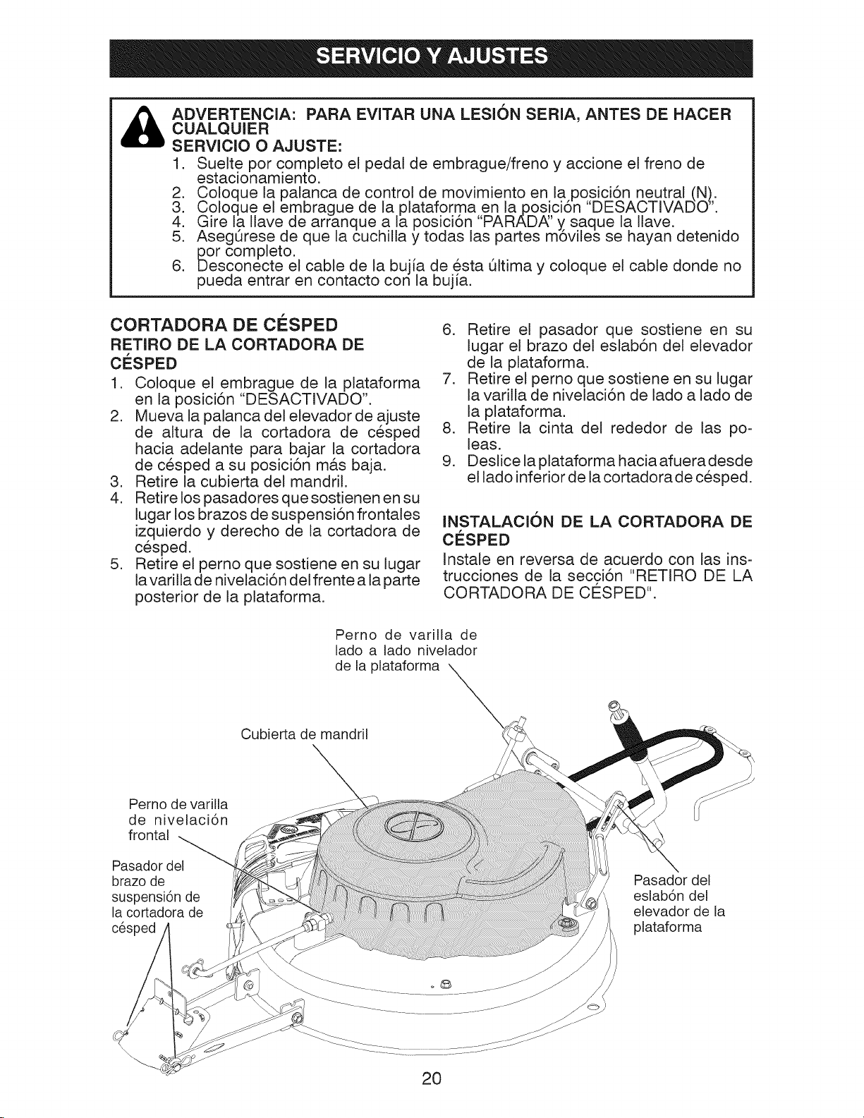
&
ADVERTENCIA: PARA EVITAR UNA LESION SERIA, ANTES DE HACER
CUALQUIER
SERVlClO O AJUSTE:
1. Suelte por completo el pedal de embrague/freno y accione el freno de
estacionamiento.
2. Coloque la palanca de control de movimiento en la posici6n neutral (N).
3. Co!oclue el embrague de la plataforma,en la posici6n DESACTIVADO _'.
4. Gire la Ilave de arranque a la posici6n PARAD,_' y saque la Ilave.
5. AsegSrese de que la cuchilla y todas las partes m6viles se hayan detenido
i_or completo.
6. Desconecte el cable de la bujfa de esta 51tima y coloque el cable donde no
pueda entrar en contacto con la bujia.
CORTADORA DE ClaSPED
RETIRO DE LA CORTADORA DE
ClaSPED
1. Coloque el embrague de la plataforma
en la posici6n "DESACTIVADO".
2. Mueva la palanca del elevador de ajuste
de altura de la cortadora de cesped
hacia adelante para bajar la cortadora
de cesped a su posici6n m&s baja.
3. Retire la cubierta del mandril.
4. Retire los pasadores que sostienen en su
lugar los brazos de suspensi6n frontales
izquierdo y derecho de la cortadora de
cesped.
5. Retire el perno que sostiene en su lugar
la varilla de nivelaci6n del frente a la parte
posterior de la plataforma.
Perno de varilla de
lado a lado nivelador
de la plataforma
Cubierta de mandril
6. Retire el pasador que sostiene en su
lugar el brazo del eslab6n del elevador
de la plataforma.
7. Retire el perno que sostiene en su lugar
la varilla de nivelaci6n de lado a lado de
la plataforma.
8. Retire la cinta del rededor de las po-
leas.
9. Deslice la plataforma hacia afuera desde
el lado inferior de la cortadora de cesped.
INSTALAClON DE LA CORTADORA DE
CESPED
Instale en reversa de acuerdo con las ins-
trucciones de la secci6n "RETIRO DE LA
CORTADORA DE CO:SPED".
Perno de varilla
de nivelaci6n
frontal
Pasador del
brazo de
suspensi6n de
la cortadora de
cesped
Pasador del
eslab6n del
elevador de la
plataforma
20
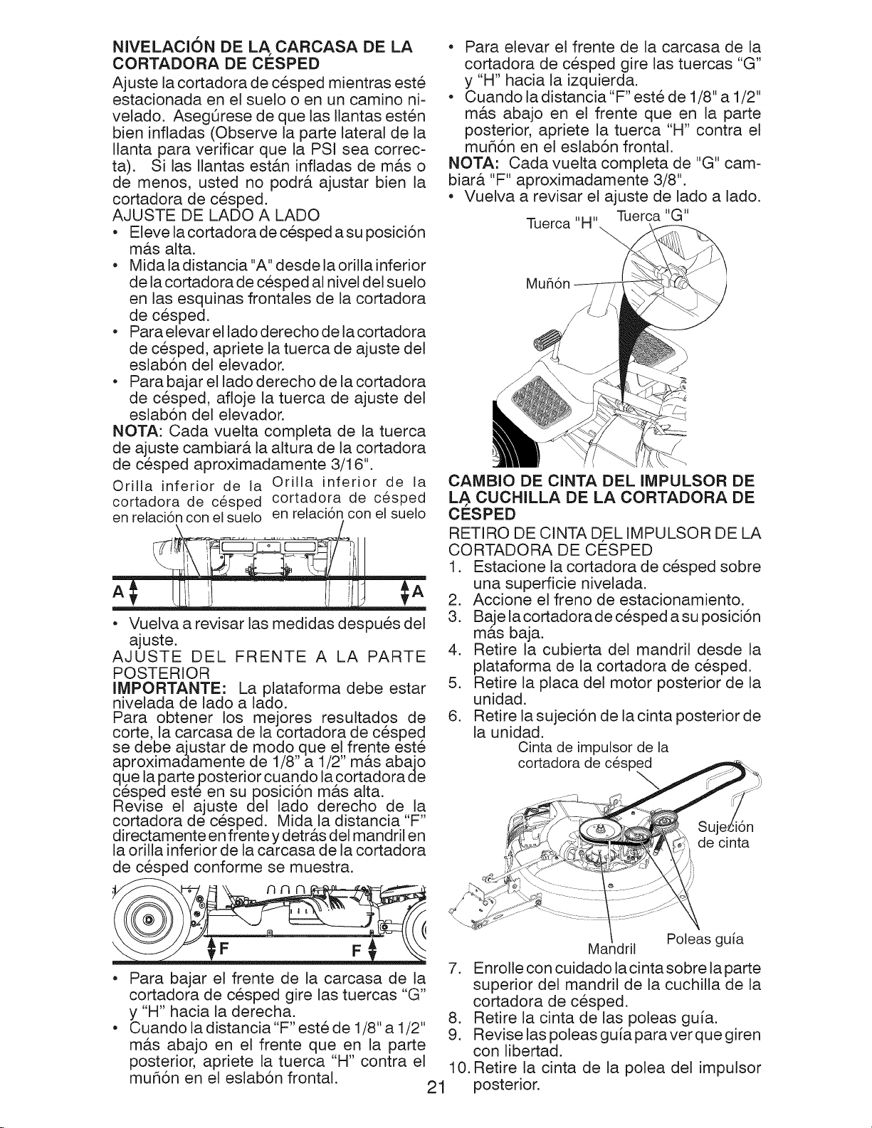
NIVELACION DE LA CARCASA DE LA
CORTADORA DE CESPED
Ajuste la cortadora de cesped mientras este
estacionada en el suelo o en un camino ni-
velado. AsegQrese de que las Ilantas esten
bien infladas (Observe la parte lateral de la
Ilanta para verificar que la PSI sea correc-
ta). Si las Ilantas est&n infladas de m&s o
de menos, usted no podr& ajustar bien la
cortadora de cesped.
AJUSTE DE LADO A LADO
• Eleve la cortadora de cesped a su posici6n
m&s alta.
• Mida la distancia "A" desde la orilla inferior
de la cortadora de cesped al nivel del sue!o
en las esquinas frontales de la cortadora
de cesped.
• Para elevar el lado derecho de la cortadora
de cesped, apriete la tuerca de ajuste del
eslab6n del elevador.
• Para bajar el lado derecho de la cortadora
de cesped, afloje la tuerca de ajuste del
eslab6n del elevador.
NOTA: Cada vuelta completa de la tuerca
de ajuste cambiar& la altura de la cortadora
de cesped aproximadamente 3/16".
Orilla inferior de la Orilla inferior de la
cortadora de cesped cortadora de cesped
en relaci6n con el suelo en relaci6n con el suelo
• Vuelva a revisar las medidas despues del
ajuste.
AJUSTE DEL FRENTE A LA PARTE
POSTERIOR
IMPORTANTE: La plataforma debe estar
nivelada de lado a lado.
Para obtener los mejores resultados de
corte, la carcasa de la cortadora de cesped
se debe ajustar de modo que el frente este
aproximadamente de 1/8"a 1/2" m_ts abajo
que la parteposterior cuando la cortadora de
cesped este en suposici6n m&s alta.
Revise el ajuste del lado derecho de,,la
cortadora de cesped. Mida la distancia F"
directamente en frente y detr_.s del mandril en
la orilla inferior de la carcasa de la cortadora
de cesped conforme se muestra.
• Para elevar el frente de la carcasa de la
cortadora de cesped gire las tuercas "G"
y "H" hacia la izquierda.
• Cuando la distancia "F" este de 1/8" a 1/2"
m&s abajo en el frente que en la parte
posterior, apriete la tuerca "H" contra el
muh6n en el eslab6n frontal.
NOTA: Cada vuelta completa de "G" cam-
biar& "F" aproximadamente 3/8".
• Vuelva a revisar el ajuste de lado a lado.
Tuerca "H" Tuerca "G"
CAIVlBIO DE ClNTA DEL IMPULSOR DE
LA CUCHILLA DE LA CORTADORA DE
CESPED
RETIRO DE CINTA DEL IMPULSOR DE LA
CORTADORA DE CO:SPED
1. Estacione la cortadora de cesped sobre
una superficie nivelada.
2. Accione el freno de estacionamiento.
3. Baje la cortadora de cesped a su posici6n
m&s baja.
4. Retire la cubierta de! mandril desde la
plataforma de la cortadora de cesped.
5. Retire la placa del motor posterior de la
unidad.
6. Retire la sujeci6n de la cinta posterior de
la unidad.
Cinta de impulsor de la
cortadora de cesped
\
:lOB
de cinta
Para bajar el frente de la carcasa de la
cortadora de cesped gire las tuercas "G"
y "H" hacia la derecha.
Cuando la distancia "F" este de 1/8" a 1/2"
m&s abajo en el frente que en la parte
posterior, apriete la tuerca "H" contra el
mufi6n en el eslab6n frontal.
Ma dril
7. Enro!le con cuidado la cinta sobre la parte
superior del mandril de la cuchilla de la
cortadora de cesped.
8. Retire la cinta de las poleas guia.
9. Revise las poleas guia paraverque giren
con libertad.
10. Retire la cinta de la polea del impulsor
21
posterior.
Poleas guia

INSTALACIONDECINTAD,ELIMPULSOR
DE LACORTADORADECESPED
Instaleenreversadeacuerdoconlasinstruc-
cionesdelasecci6n"RETIRODELACINTA
DE,L IMPULSORDELA CORTADORADE
CESPED".
AJUSTE DE FRENO
Lacortadorade cespedest&equipadacon
un sistema de freno ajustable que est&
montado en el lado derecho del transeje.
Si la cortadora de cesped requiere m&s de
cuatro (4) pies (1.21 9 metros) de distancia
para detenerse a lavelocidad m&xima sobre
una superficb de concreto o pavimento
seco nivelado, entonces el freno se debe
ajustar.
1. Estacione la cortadora de cesped sobre
una superficb nivelada.
2. Suelteel pedaldelfreno/estacionamiento.
3. Midaladistanciaentreel rotorylapastilla
del freno si la distancia entre el rotor y
la pastilla del freno es de un espacio de
m&s de .02", entonces el freno necesita
ajustarse.
RUEDA POSTERIOR
1. BIoquee bien el eje posterior.
2. Retire la cubierta para polvo, el anillo de
retenci6n, la arandela y la llave cuadra-
da mientras jala la Ilanta hacia afuera.
3. Repare la Ilanta y vuelva a ensamblar-
la.
4. Vuelva a colocar la Ilave cuadrada mien-
tras pone la Ilanta de vuelta en su lugar,
luego coloque bien la arandela y el anillo
de retenci6n en la ranura del eje, cuando
empuje la Ilanta de vuelta a su lugar sobre
el eje meta la mano por debajo y jab la
rueda dentada de la cadena hacia usted
para facilitar la colocaci6n de la Ilanta.
NOTA: Para sellar las pinchaduras de
las Ilantas y evitar que estas se desinflen
debido alas fugas lentas, compre y use
sellador para Ilantas. E! sellador de Ilantas
tambien previene la podredura en seco y
la corrosi6n de las Ilantas.
Arandela
Rotor
Pastilla de
frenos
Tuerca
4. Apriete la tuerca de pinza hasta que
alcance el espacio de .02".
NOTA: Puede ser necesario usar un ca-
librador de hoja para obtener la medida
correcta.
AJUSTE DE LA ALINEACI6N DEL
VOLANTE
Si los travesaSos del volante no est&n en
posici6n horizontal (de izquierda a derecha)
cuando las ruedas est&n en posici6n recta
hacia adelante, mueva e! volante y reens&m-
blelo de acuerdo con I,as instrucciones de la
secci6n "INSTALACION DE LA COLUMNA
DE DIRECCION " de este manual.
CAMBIO DE RUEDA PARA
REPARACION
RUEDA FRONTAL
1. Bloquee bien el eje frontal.
2. Retire la cubierta para polvo, el anillo de
retenci6n y la arandela para poder retirar
la rueda.
3. Repare la Ilanta y vuelva a ensamblarla.
4. Vuelva a colocar bien la arandela y el
anillo de retenci6n en la ranura del eje.
Anillo retenedor _t
Cubierta
de polvo
ARRAN, QUE DEL MOTOR CON UNA
BATERIA
DESCARGADA
_, PRECAUCI6N: Las baterias de plomo
&cido generan gases explosivos. Mantenga
los materiales que producen chispas, flamas
y humo lejos de las baterias. Use siempre
una protecci6n para los ojos cuando este
cerca de las baterias.
Si su bateria est& demasiado baja como para
arrancar el motos, esta se debe recargar.
(Consulte la parte de "BATE Ri,_' en la secci6n
de Mantenimiento de este manual).
NOTA: Esta unidad estA equipada con un
sistema de arranque manual del motor que
se puede usar si la bateria estA demasiado
descargada como para arrancarto. Consul-
te la parte de "SISTEMA DE ARRANQUE
MANUAL' en la secci6n de Operaci6n de
este manual.
22
_÷'_"- Llave cuadrada
(s61o en la rueda posterior)
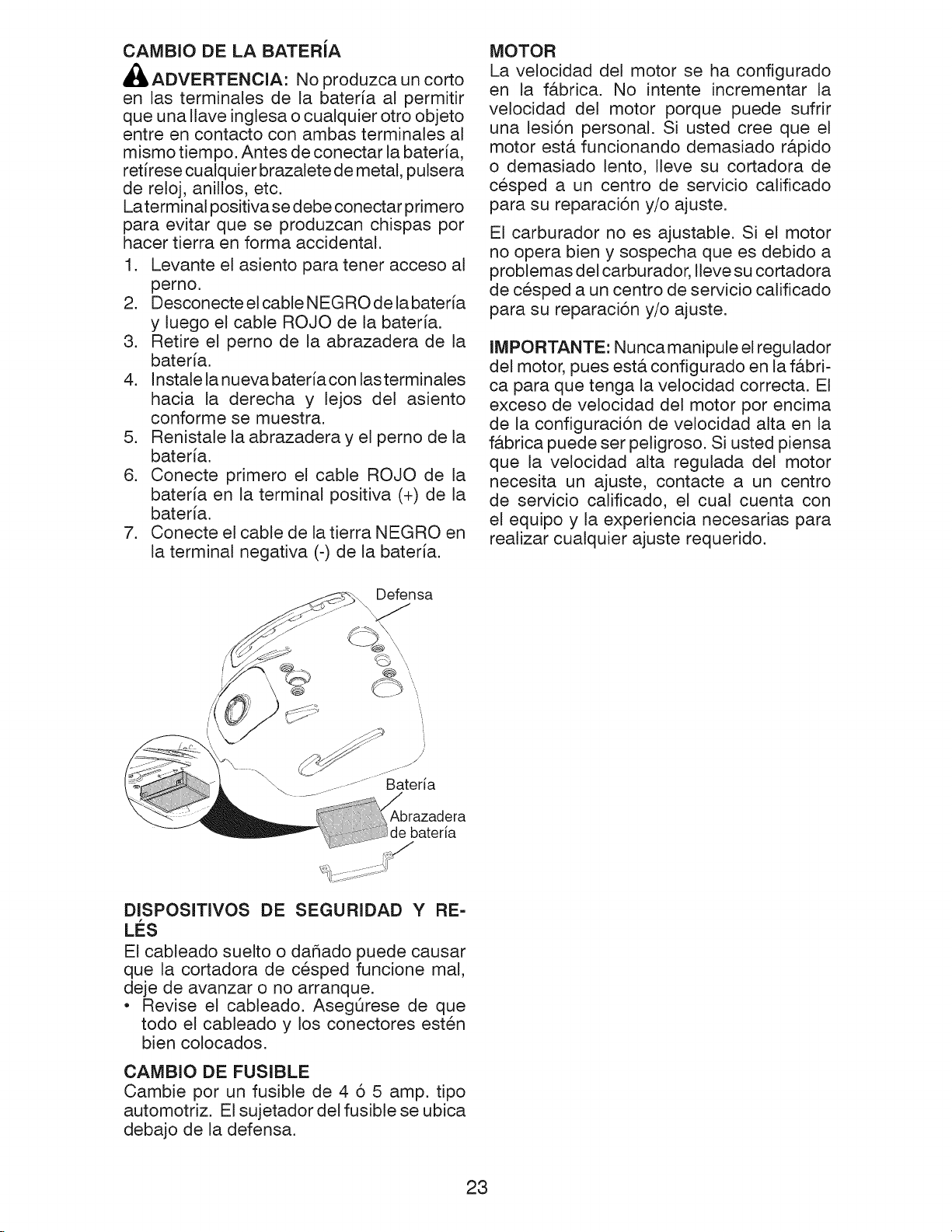
CAMBIO DELA BATERiA
_,ADVERTENCIA: No produzca un corto
en las terminales de la bateria al permitir
que una Ilave inglesa o cualquier otro objeto
entre en contacto con ambas terminales al
mismo tiempo. Antes de conectar la bateria,
retirese cualquier brazalete de metal, pulsera
de reloj, anillos, etc.
Laterminal positiva se debe conectar primero
para evitar que se produzcan chispas por
hacer tierra en forma accidental.
1. Levante el asiento para tener acceso al
perno.
2. Desconecte el cable NEGRO de la bateria
y luego el cable ROJO de la bateria.
3. Retire el pemo de la abrazadera de la
bateria.
4. Instale la nueva bateria con lasterminales
hacia la derecha y lejos del asiento
conforme se muestra.
5. Renistale la abrazadera y el pemo de la
bateria.
6. Conecte primero el cable ROJO de la
bateria en la terminal positiva (+) de la
bateria.
7. Conecte el cable de la tierra NEGRO en
la terminal negativa (-) de la bateria.
MOTOR
La velocidad del motor se ha configurado
en la f&brica. No intente incrementar la
velocidad del motor porque puede sufrir
una lesi6n personal. Si usted cree que el
motor est,. funcionando demasiado r&pido
o demasiado lento, Ileve su cortadora de
cesped a un centro de servicio calificado
para su reparaci6n y/o ajuste.
El carburador no es ajustable. Si el motor
no opera bien y sospecha que es debido a
problemas del carburador, Ileve su cortadora
de cesped a un centro de servicio calificado
para su reparaci6n y/o ajuste.
IMPORTANTE: Nunca manipule el regulador
del motor, pues est& configurado en la f&bri-
ca para que tenga la velocidad correcta. El
exceso de velocidad del motor por encima
de la configuraci6n de ve!ocidad alta en la
f&brica puede ser peligroso. Si usted piensa
que la velocidad alta regulada del motor
necesita un ajuste, contacte a un centro
de servicio calificado, el cual cuenta con
el equipo y la experiencia necesarias para
realizar cualquier ajuste requerido.
Defensa
Abrazadera
bateria
DISPOSmVOS DE SEGURIDAD Y RE-
LES
El cableado suelto o dahado puede causar
que la cortadora de cesped funcione mal,
deje de avanzar o no arranque.
• Revise el cableado. AsegOrese de que
todo el cableado y los conectores esten
bien colocados.
CAMBIO DE FUSIBLE
Cambie por un fusible de 4 6 5 amp. tipo
automotriz. El sujetador del fusible se ubica
debajo de la defensa.
23

Prepare de inmediato su cortadora de cesped
para almacenarla al final de la temporada o si
no Io va a utilizar durante 30 dias o m&s.
ADVERTENClA: Nunca almacene la
cortadora de cesped con gasolina en el
tanque adentro de un edificio donde los
humos puedan alcanzar una flama abierta
o una chispa. Permita que el motor se
enfrie antes de almacenarla en cualquier
lugar cerrado.
CORTADORA DE CESPED
Retire la plataforma de la cortadora de
cesped para su almacenamiento durante
el invierno. Cuando vaya a almacenar la
cortadora de cesped durante un tiempo,
limpiela a conciencia, retire toda la sicuedad,
grasa, hojas, etc. Almacenela en un &rea
limpia y seca.
1. Limpie toda la cortadora de cesped (con-
suite la parte de "LIM PIEZA' en la secci6n
de Mantenimiento de este manual).
2. Inspecioneycambie lacinta,, si es nece-
sario (consulte la parte de instrucciones
de cambio en la secci6n de Servicio y
Ajustes de este manual).
3. Lubrique conforme se indica en la secci6n
de Mantenimiento de este manual.
4. AsegQrese de que todas las tuercas,
pernos y tornillos esten bien apretados.
Inspeccione las partes m6viles en busca
de alg0n daho, rotura y desgaste. C&m-
bielas si es necesario.
5. Retoque todas las superficies de pintura
oxidadas o despostilladas, lije un poco
antes de pintar.
BATERiA
• Cargue por completo la bateria antes de
almacenar.
• Si la bateria se retira de la cortadora de
cesped para almacenarla, no almacene la
bateria directamente sobre superficies de
concreto o hOmedas.
MOTOR
SISTEMA DE COMBUSTIBLE
IMPORTANTE: Es importante evitar que
se formen dep6sitos de goma en las partes
esenciales del sistema de combustible como
el carburador, la manguera de combustible
o el tanque durante el almacenamiento.
Asimismo, los combustibles mezclados con
alcohol (llamados gasoho! o que usan etano!
o metanol) pueden atraer la humedad, !o
que provoca la separaci6n y formaci6n de
&cidos durante el almacenamiento. El gas
&cido puede dar_ar el sistema de combus-
tible de un motor mientras se encuentra en
almacenamiento.
• Vacie el tanque de combustible al arrancar
el motor y dejarlo funcionar hasta que las
lineas de combustible y el carburador
esten vacios.
• Nunca use productos limpiadores para
motor o carburador en el tanque de com-
bustible porque puede ocurrir un daho
permanente.
• Use combustible nuevo en la pr6xima
temporada.
NOTA: El estabilizador de combustible es
una alternativa aceptable para minimizar
la formaci6n de dep6sitos de goma de
combustible durante el almacenamiento.
Agregue estabilizador a la gasolina en el
tanque de combustible o recipiente de al-
macenamiento. Siga siempre la proporci6n
de mezcla que se encuentra en e! recipiente
de! estabilizador. Deje funcionar el motor
a! menos durante 10 minutos despues de
agregar el estabilizador para permitir que
el estabilizador Ilegue al carburador. No
vacie el tanque de gasolina y e! carbura-
dor si utiliza estabilizador de combustible.
ACEITE DEL MOTOR
Drene el aceite (con e! motor tibio) y cambielo
por, aceite de motor limpio. (Consulte la parte
de MOTOR" en la secci6n de Mantenimiento
de este manual).
ClLINDRO(S)
1. Retire la(s) bujia(s).
2. Vierta una onza de aceite por el(los)
orificio(s) de la(s) bujia(s) hacia el(los)
cilindro(s).
3. Gire la Ilave del arranque a la posici6n
de 'ARRANQUE" durante unos cuantos
segundos para distribuir el aceite.
4. Coloque la(s) bujia(s) nueva(s).
OTROS
• No almacene la gasolina de una estaci6n
a otra.
• Cambie la lata de la gasolina si comienza
a oxidarse. E! 6xido y/o la suciedad en la
gasolina causar& problemas.
• Si es posible, almacene la cortadora de
cesped en interiores y cObrala para pro-
tegerla del polvo y la suciedad.
• Cubra la cortadora de cesped con una
cubierta protectora adecuada que no
retenga la humedad. No use pl&stico. El
pl&stico no puede respirar, Io que permite
que se forme condensaci6n y causar& que
la cortadora de cesped se oxide.
IMPORTANTE: Nunca cubra la cortadora
de cesped mientras el mo tory las &reas de
escape todavia esten calientes.
24

TABLA DE SOLUCION DE PROBLEMAS:
PROBLEMA CAUSA
NO arral3ca
Dificultad para arrancar
El motor no 1 ElfrenodelembragueifTenonoesta.presionado. 1 Presione el pedal del emgrague/freno.
da vueltas
El motor chasquea 1
pero 2
no arranoa
Perdida de energia 1 Oortededemasiadocesped/demasiado rb,pido. 1 Elevelaalturadecorte/reduzcalavelocidad.
Vibraci6n excesiva 1 1 Cambielacuchilla.Aprieteelpernodelacuchilla.
1 No tiene combustible.
2 Bujia defectuosa.
3 Filtro de aire sucio.
4 Agua en el combustible.
5 Cableado suelto odaSado. 5
6 Lasvalvulasdelmotorestan desajustadas. 6
1 Filtro de airesucio. 1
2 Bujia defectuosa. 2
3 Bateria bajao muerta. 3
4 Combustibleviejo o sucio. 4
5 Cableado suelto oda_ado.
6 Lasv_.lvulasdel motorest_.ndesajustadas. 6 Contactea uncentrode serviciocalificado.
2
Elembraguede laplataformaest,.activado. 2
3
Bateria baja o muerta. 3
Fusiblefundido. 4
4
Terminales de bateria con corrosi6n. 5
5
Cableado suelto o daSado. 6
6
7
Interruptor de arranque defectuoso. 7
8
Solenoide o arranque defectuoso. 8
9
Interruptor(es)de presencia de operador defectuoso(s), 9
Bateria baja o muerta. 1
Terminales de bateria con corrosi6n. 2
3
Cableado suelto o da_ado. 3
4
Solenoide o arranque defectuoso. 4
2 Acumulaci6n de cesped hojas y basura 2 Limpiela parte inferiorde lacarcasa de la
deba o de la cortadora de cesped, cortadora de cesped.
3 Filtro de aire sucio. 3 Limpie/cambie el filtro de aire.
4 Nivel bajo de aceite/aceite sucio. 4 Reviseel nivel de aceite/cambieelaceite.
5 Bujia defectuosa. 5 Limpiey ajuste o cambie la bujia.
6 Combustible viejo o sucio. 6 Vacie eltanque de combustible y rellenelo
7 Agua en el combustible. 7 Vacieeltanquedecombustibleyelcarburadory
8 Cable de la bujia suelto. 8 Conectey ajusteel cablede la bujia.
Pantalla/aletas de aire del motor sucias.
9 9 Limpiela pantalla/aletasde airedel motor.
Silenciador sucio/obstruido.
10 10 Limpie/cambieel silenciador.
Cableado suelto o da_ado.
11 11 Revisetodoel cableado.
12 12 Contacteaun centrode serviciocalificado.
Lasvalvulasdel motoresta.ndesajustadas.
Cuchilla desgastada, doblada osuelta.
2 2 Contactea uncentrode servioiooalificado.
Mandril de cuchilla doblado.
3 3 Apriete la(s) parte(s) suelta(s)/
Parte(s)suelta(s)/da_ada(s).
CORRECCl6N
m
1 Llene eltanque de combustible.
2 Cambie labujia.
3 Limpie/cambie elfiltro de aire.
4 Vacie el tanque de combustible y el
carburador relleneel tanque con qasolina
nuevay cambie e fi trode combust]be.
Revisetodo elcableado.
Contacteauncentrode serviciocalificado.
Limpie/cambie elfiltro de aire.
Cambie labujia.
Recargue o cambie la bateria.
Vacie el tanquede combustible y rellenelo
con gasolina nueva ylimpia.
Revisetodo elcableado.
Desactive el embrague de la plataforma.
Recargue o cambie la bateria.
Oambie el fusible.
Limpie lasterminales de la bateria.
Revisetodo elcableado.
Revise/cambieel interruptorde arranque.
Revise/cambie el solenoide o arranque.
Contactea uncentrode servioiooalificado.
Recargue o cambie la bateria.
Limpie lasterminales de la bateria.
Revisetodo elcableado.
Revise/cambie el solenoide o arranque.
con gasolina nueva ylimpia.
relleneeltanquecongasolinanueva.
daSada(s).
Cambie laspartes daSadas.
25

TABLA DE SOLUCION DE PROBLEMAS:
PROBLEMA
Elmotot sigue
funcionando cuandoel
operadordeja el asiento
CAUSA
1
Sistema de control de presencia de
seguridad del operador defectuoso.
CORRECCK_N
1
Reviseel cableado, los interruptores y las
conexiones. Sino son correctos contacte
a un centro de servicio ca ificado.
conelembragueactivado
Corte deficiente =
corte no uniforme
La cuchilla de la 1 Obstrucci6nenel mecanismodelembrague. 1 Retire la obstrucci6n.
cortadora de c6sped 2 CintadelimpuEsordeEacortadoradecespeddesgastada/daSada,2 Cambielacintadelimpulsordelacortadoradecesped.
no gira
Descarga de cesped 1 Velocidaddeavancedemasiadorapid& 1 Cambie a una velocidad m_.slent&
deficiente 2 C6sped hQmedo. 2 Permitaqueelcespedsesequeantesdepodarlo,
La bateria no 1 Celda(s) de bateria defectuosa(s). 1 Cambie la bateria.
carga 2 Conexiones de cable defectuosas. 2 Revise/limpie todas las conexiones.
1 Cuchilla desgastada, doblada o suelta.
2 Plataformadecortadoradecespednonivelada,
3 Acumulaci6n de cesped hojas y basura
debajo de a cortadora de cespe&
4 Mandril de cuchilla doblado.
5 Respiradero de la cortadora de cesped
obstruido por la acumulaci6n de cesped,
hojasy basuraalrededordel mandril.
3 Polea de guia congelada. 3 Cambie la polea de guia.
4 Mandril de cuchilla congelado. 4 Contacteaun centrodeserviciocalificado.
3 Plataformadecortadoradecespednonivelada, 3 Nivelelaplataformadelacortadoradecesped
4 Presi6ndeairedelasIlantasbaja/nouniforme. 4 Revisequela PSIdelasIlantasseaadecuada.
5 Cuchilla desgastada,dobladao suelta. 5 Cambie/afile lacuchilla. Apriete el perno
6 Acumulaci6nde cesped hojasv 6 Limpiela parte inferiordela carcasade la
basuradebajode a cortadora decesped, cortadoradecesped.
7 Cintadeimpuls0rdelac0rtad0radec6speddesgastada,
8 Cuchilla mat instatada.
9 Uso inapropiado de cuchitla.
10 Orificios del respiradero de la cortadora 10 Limpiealrededor de los mandriles para
de cesped obstruidos pot la acumulaci6n abrir losorificios del respiradero.
de cesped hojas y basura alrededor de
os mandri es.
3 Alternador defectuoso. 3 Cambie el alternador.
m
1 Cambielacuchilla,AprieteelpernodelacuchiIta.
2 Nivelelaptataformadetacortadoradecesped.
3 Limpiela parte inferior de la carcasa de la
cortadora de cesped.
4 Contacteaun centrodeserviciocalificado.
5 Limpiealrededor de los mandriles para
abrir los orificios del resplraaero.
de la cuchilla.
7 Oambiela cinta delimpulsorde la cortadorade c_sped,
8 Reinstatelaorittafitosadelacuchiltahaciaabajo,
9 Cambie pot unacuchilla de la lista de
este manual.
Perdida de impulso 1 Control de rueda libre en posici6n 1 Colgq,ueei control de la rueda libre en la
El tractor se ponen mar- 1 -l sistema de funcionamiento atr&s 1 Girar et ROSen la posici6n "ON".Vea
.'ha atr_s ',ROS)no est&"ON", cuando enganche la secci6n de operaci6n.
"DESACTIVAD,_'. poslclon 'ACTIVADO".
3 Falta la Ilave del eje. 3 InstalelaIlavedeleje en,la ruedaposterior.
a segadora o otro accesorio.
Consultela partede "COMORET1RARLA
RUED#:'enlasecci6ndeServicioyAjustes.
26

CORTADORA DE CESPED - - NOMERO DE CATALOGO 28600
ESQUEMA
SCH21-S
FUSIBLE-5A
.... i .....
FUSIBLE-40A
"_B_ M
A1
_ _' I , I J' I ,a. B C D E F'
__ : c,..............................................;O ' O,_ O O
BATERIA
RELEVO DE MOTOR MOTOR DE
DE ARRANQUE ARRANQUE
.... ,
BLANCO
BLANCO
r_, ,____; ....
I I i I BT_NCO
" .... $
......... _ ........ :_1 I t _ i
EMBRAOUE FRENO ACCESORIO DEL F I
........ 4a * ........... O @ DE SEGURIDAD
A) EMBRAGUE k i
k A_:_%__
..... -- "Y-_--]- --,_A7r:7_...................................__}_..............................4
@RIS i I NEGRO
INTERRUPTOR DE REVERSA k.-' v; | "-J _ i
(NO EN REVERS.&) -ddl#E('% _3P. _)E -
........................................................f
"_ [ eMARILLO j_ _ CORTOCIRCUITOS NEGRO I_
t ....... t
i !
t k t
INTERRL?TOR DE ENCENDIDO
POSICION CIRCUITO _&£a.RCA>>
APAG._O M+G+A 1
_NTR FN FL_'C ION_TO _\_AR B+AI
_ONERENFUNCIONAMIENTO B+A 1 L+A2
ARtLa.NCAR 3 + S + AI
........................................EEORg:BTAEf9 _ LENTDAD DE %
NOTA SOBRE LAS ABRAZADERAS DE
AISLAMIENTO DEL CABLEADO: SI SE
QUITAN LAS ABP_a.ZADEP_a.S DE
AISLAMIENTO DEL CABLEADO PARA
HACER EL MANTENIMIENTO DE LA
LEX'IDAD, SE LAS DEBEtL_ FNSTALAR
NUEVAMENTE PARA PROTEGER EL
(ABLEADO ADE( UADAMENTE
ENCENDIDO
SALIDA DEL SISTEiVL¢ DE MiNIMO DE CORRIENTE ALTERNA
(ARGA DE 5 AiVlPERIOS DE 28 VOLTIOS ,@ 3600 RPM
DE CC @: 3600 _M (COBRO DE SISTE_L_ DESCON_ECT,_O)
MODLZO DE SEGURIDAD ES VISTO
DESDE LADO DE CON_ (TANDO
t
q
HLTCO DE BUJIA
DIODO ................................
ESTATOR
®
CONEXIONES NO
DESMONTABLES
---_%--
CONEXIONES
DESMONTABLES
27

CORTADOR._ DE ClaSPED - - NOMERO DE CATALOGO 28600
COMPONENTES ELECTRICOS
LRV1
i i i
i i i
i
s
l,
I
i
i i i
i
i
i
i
11
i
i
i i
s
i
i
i
i
i
1
5
6
u t" s
s i a i
i
i
t
3 4
@
2
\
12
10
9
/
8
7
28

CORTADORA DE CESPED - - NOMERO DE CATALOGO 28600
COMPONENTES ELECTRICOS
CLAVE PARTE
NO. NO. DESCRIPCI6N
1 437070 BATER[A
2 425416 POLIURETANO DE ESPUMA
3 193350 INTERRUPTOR DE IGNICI6N ROS
4 411934 LLAVE
5 433330 FUSIBLE 5A
6 425937 FUSIBLE 40A
7 160784 INTERRUPTOR
8 431542 RELE'_40A
9 109553X INTERRUPTOR
10 176138 INTERRUPTOR
11 431846 RETROCESO QUE COMIENZA MODULO LRV
12 192749 INTERRUPTOR ROS
13 428477 GUARNICIONES DE IGNICION
NOTA: Las dimensiones de todos los componentes se proporcionan en
pulgadas estadounidenses 1 pulgada = 25.4 mm
29

CHAStS
CORTADORA DE Ce--SPED" "NOMERO DE L;_ _,--'-"_'-
42
_......... 29
...............30
4sJso_/
LRV-ChasSis_l r2
46
/
3O

CHASIS
CORTADORA DE ClaSPED - - NOMERO DE CATALOGO 28600
CLAVE PARTE
NO. NO. DESCRIPClON
1 428048
2 428247
3 428244
4 428346
5 428110
6 428109
7 428040
8 428576
9 428856
10 195530
11 174648X431
12 428248
13
14
15
16
17 428348
18 428047
-- 432389
-- 435674
19 428986
20 428046
21 429815
22 428826
23 149846
24 416358
25 72140424
26 73510400
27 430087
28 428301
29 430817
30 430470
31 430469
32 150406
33 124181X
34 121250X
35 72050412
36 127018X
37 19171912
38 166369
39 134300
40 121248X
41 123976X
42 171852
43 73800500
44 428243
45 17000512
46 17490508
47 86777
48 408981
49 17060516
50 165492
428251X665 CUBIERTA, DESCANSO PARA PIE
428250 ESTRUCTURA, DESCANSO PARA PIE
428249 SOPORTE, DESCANSO PARA PIE
428241X665 CONTROL DE DEFENSA
SOLDADURA, CHASIS
SOPORTE, AXEL LH
SOPORTE, AXEL RH
CORAZA, FRENTE DE TRANSEJE
SOPORTE, CRUZ DEL EJE
CUBIERTA, IMPULSOR DE FRICCION
PLACA, MOTOR
ABRAZADERA, FRENTE DE CHASIS
ABRAZADERA, SOPORTE DE DIRECCION
TABLA, ASIENTO
ABRAZADERA. MONTAJE DE INTERRUPTOR
FUNDA, POLVO
PROTECCION, MOTOR
MOTOR, (NON-CALIFORNIA) 12S907-1411 -B1
MOTOR, (CALIFORNIA) 121 S07-1415-F1
MOTOR, (CANADA) 12S907-1463-B1
SUJECION, CINTA
ABRAZADERA, BATE R[A
PALANCA, INTERRUPTOR
MVA DE PLATAFORMA DE EMBRAGUE
PERILLA
TORNILLO, NO. 10
PERNO, CARRO - 1/4-20 X 3
TUERCA, 1/4-20
ESPACIADOR, MOTOR
DISCO, MVA DE FRICCION
PERNO, SCKT HD 3/8-24 X 1 .25
COJINETE
ESPACIADOR, NEUTRAL
PERNO, 3/8-16 X 1 .280
RESORTE, ASIENTO
RESORTE
PERNO, 1/4-20 X 1 1/2
PERNO, RESALTO
ARANDELA, 17/32 X 1 3/16
PERILLA, ASIENTO
ESPACIADOR
MANGUITO, BROCHE DE NAILON
TUERCA, CIERRE
PERNO, REBORDE 5/16-18
TUERCA, 5/16-18
ASIENTO
PERNO, 5/16-18 X 3/4
PERNO, 5/16-18 X 1/2
TORNILLO
RODAMIENTO DE LA BRIDA
SCREW 5/16-18 x 1
PERNO, 5/16-18 x .561
NOTA: Las dimensiones de todos los componentes se proporcionan en
putgadas estadounidenses 1 putgada = 25.4 mm
31

CORTADORA DE ClaSPED - - NOMERO DE CATALOGO 28600
IMPULSOR
,67
68
LRV-Drive 1 r3
32

CORTADORA DE ClaSPED - - NOMERO DE CATALOGO 28600
IMPULSOR
CLAVE PARTE CLAVE PARTE
NO. NO. DESCRIPCiON NO. NO. DESCRJPCION
72110406
73800400
PERNO, CARRO - 114-20 X 3/4
TUERCACIERRE DE NAILON
114-20
165492
74780412
10040400
19091210
166002
73680400
PERNO, REBORDE
PERNO, 1/4-20 X 3/4
ARANDELA, CIERRE
ARANDELA PLANA
ARANDELA, SERRADA
TUERCA, CIERRE DE CORONA
114-20
17490436
19091016
17490420
430249
TORNILLO 1/4-20 X 2 114
ARANDELA
TORNILLO, 1/4-20 X 1 1/2
FRENO DE PLACA
ANTIGI RATORIO
430245
RESORTE, RETORNO DEL
FRENO
428021
430247
428078
77010810
428019
428017
435253
428016
4497H
17490508
428460
427945
429678
BRAZO, FRENO
RETORNO DE ESPACIADOR
MORDAZA ,MVA DE FRENO
PASADOR, CLAVlJA 1/4
PLACA, PASTILLA DE FRENO
FRENO DE DISCO
ROTOR, FRENO
TAPA, PINZA DE FRENO
PASADOR, RETENEDOR
PERNO, 5/16-16 X 112
CABLE, FRENO
SOLDADURA, PEDAL
VARILLA, FRENO DE ESTACIO
NAMIENTO
77100812
76020208
429325
PASADOR, HORQUILLA.25X.75
PASADOR, DIA. 1/16 CHAVETA
ABRAZADERA, SOPORTE DE
FRENO
429694
429693
17490406
428070
PEDAL DE CUBIERTA
CUBIERTA, PEDAL DE FRENO
TORNILLO, 1/4-20 X 3/8
MONTAJE DE CABLE DE
ABRAZADERA
17000512
PERNO, 5/16-18 X 3/4
104757X613 CASQUILLO
12000002 ANILLO E #5133-62
429519 PINON
1
2
3
4
5
6
7
8
10
11
12
13
14
15
16
17
18
19
20
21
22
23
24
25
26
27
28
DES
29
30
31
32
33
34
35
436144 SERVICIO CON JUNTOS, 36
TRANSEJE 37
428268X613 MVA DE RUEDA (POSTERIOR)
121748X ARANDELA, 16 GA. 38
12000001 SUJETADOR EN E 39
123583X LLAVE. CUADRADO 40
427939 SOLDADURA. EJE DEL 41
IMPULSOR 42
428069 IMPULSOR DE CADENA 43
427873 RUEDA DENTADA. 9 DIENTE
RANURADO 45
12100009 ANILLO, BROCHE 46
428876 MVA DIFERENCIAL 47
1370H ARANDELA, EMPUJE 48
430645 CADENA, IMPULSOR
PRINCIPAL 49
430845 MANGUITO
427946 ABRAZADERA, PORTADOR 50
9159R MVA DE COJINETE 51
427926 ENTRADA DEL EJE 52
428106 RUEDA, FRICCION A5M 53
424759 BRAZO, DESPLAZAMIENTO 54
430870 VARILLA, DERIVACION 55
427997 PARTE POSTERIOR DEL 56
PORTA DOR DE SOPORTE 57
428077 RESORTE, PORTADOR 58
428076 RESORTE, FRENO 59
431374 RESORTE, DERIVACION 60
427995 CAJA DE PORTADOR DE SO 61
PORTE 62
428303 ESLABON, DESPLAZAMIENTO
429816 BRAZO. EMBRAGUE 63
429053 PALANCA DE DESPLAZAMIEN 64
TO DE SOLDADURA 65
428302 SOPORTE, PALANCA DE
PLAZAMIENTO 66
174840 ARANDELA, NAILON 67
183900 PALANCA DE DESPLAZAMIEN 68
TO DE CUBO 69
429055 ESPACIADOR, NAILON
428464 ABRAZADERA MNTG BRAZO 70
DEDESPLAZAMIENTO 71
428461 ABRAZADERA, FLEXIONADOR 72
DE PALANCA DE CAMBIOS 73
428462 BRAZO DE DESPLAZAMIENTO
DEL TUBO
196492X428 AGARRE, MANIJA
proporcionan en putgadas estadounidenses
NOTA: Las dimensiones de todos los componentes se
1 putgada = 25.4 mm
33

CORTADORA DE CESPED - - NOMERO DE CATALOGO 28600
DIRECCION
526
23
22
7_---..__ 28
LRV-Steering_l_r2
2_c
34

CpRTADORA DE CESPED - - NOMERO DE CATALOGO 28600
DIRECCION
CLAVE PARTE
NO. NO. DESCRIPClON
1
2
3
4
5
6
7
8
9
lO
11
12
13
14
15
16
17
18
19
2o
21
22
23
24
25
26
27
28
29
30
428269X613 MVA DE RUEDA (FRONTAL)
12000001 SUJETADOR EN E
188967 ARANDELA, ENDURECIDA
121749X ARANDELA 1/4 X 3/4
428034 HUSILLO DERECHO
6266H WARANDELA, ENDURECIDA EMPUJE
3366R EMPOTRADA, COLUMNA DE DIRECCION
421076 PASADOR, CLAVIJA 5/64 X 3/4
19131414 ARANDELA
428057 SOLDADURA, EJE LWR STRG
428035 ESLABON, STRNG LH
428036 ESLABON, STRNG RH
74780524 PERNO, 5/16-18 X 1 1/2
19131016 ARANDELA
73800500 TUERCA, 5/16-18
428044 MANGUITO, BROCHE DE DIRECCION
428252 SOPORTE, DIRECCION SUPERIOR
195227 MANGUITO, DIRECCION SUPERIOR
17000512 PERNO, 5/16-18 X 3/4
428045 SUJETADOR, RESORTE DE RETENEDOR
428347 CUBIERTA, COLUMNA DE DIRECCION
428213 EJE, DIRECCION
186737 ADAPTADOR, VOLANTE
19183812 ARANDELA, 9/16 X 2 3/8 12 GA.
73940800 TUERCA, CONTRATUERCA 1/2-20
414851 X418 VOLANTE, DIRECCION
414852X418 TAPA, VOLANTE
199849 SUJETADOR, RESORTE DE RETENEDOR
428033 HUSILLO IZQUIERDO
104757X613 CASQUILLO
NOTA: Las dimensiones de todos los componentes se proporcionan en
putgadas estadounidenses 1 putgada = 25.4 mm
35
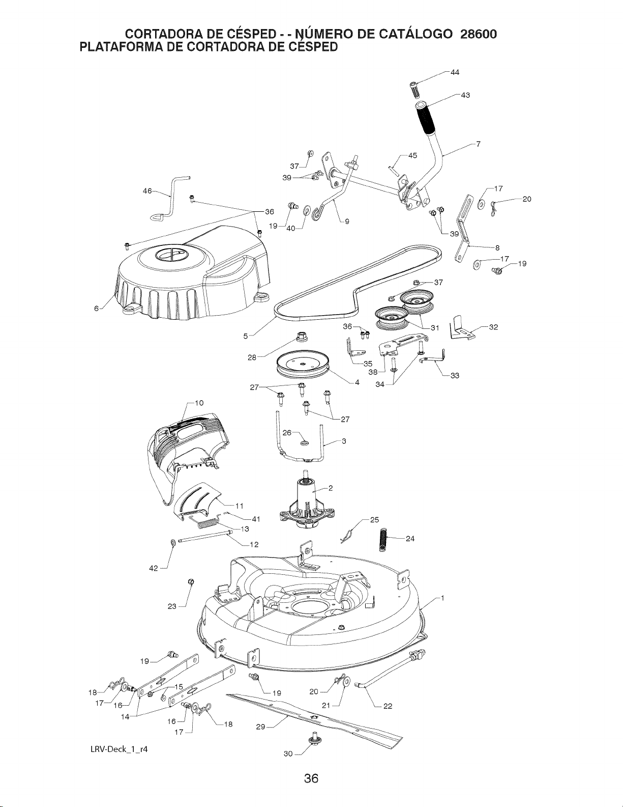
CORTADORA DE CESPED - - NOMERO DE CATALOGO 28600
PLATAFORIVlA DE CORTADORA DE CESPED
14
LRV-Deck I r4
23
F1
36

CORTADORA DE ClaSPED - - NOMERO DE CATALOGO 28600
PLATAFORIVlA DE CORTADORA DE CESPED
CLAVE PARTE
NO. NO. DESCRIPCION
1 428193 PLATAFORMA, 26"
2 192870 MVA DE MANDRIL
3 432520 SUJECION, CINTA
4 432594 POLEA, MANDRIL
5 428578 CINTA
6 428242 CUBIERTA, MANDRIL
7 429395 MVA DE ELEVADOR, PLATAFORMA
8 429195 ESLABON, ELEVADOR DE PLATAFORMA
9 429397 ESLABON, AJUSTABLE
10 438923 DEFLECTOR
11 428968 SOPORTE, DEFLECTOR
12 131491 VARILLA, BISAGRA
13 197026 RESORTE, TORSION
14 418863 BRAZO, SOPORTE DE CORTADORA DE CF:t:SPED
15 73900500 TUERCA, CIERRE
16 195161 ESPARRAGO
17 19191912 ARANDELA
18 194209 PASADOR
19 196539 PERNO, RESALTO
20 194208 PASADOR
21 19171912 ARANDELA, 17/32 X 1 3/16
22 429350 ESLABON, PLATAFORMA
23 73930600 TUERCA, CIERRE 3/8-16
24 429531 RESORTE, PLATAFORMA
25 4497H PASADOR
26 187690 ESPACIADOR, MANDRIL
27 173984 PERNO, MANDRIL
28 400234 TUERCA, CIERRE
29 428500 CUCHILLA
30 193003 PERNO, CUCHILLA
31 193197 POLEA, GU[A
32 141043 PROTEC, CION, GU[A
33 193414 SUJECION, GUIA DE CINTA
34 72110612 PERNO, 3/8-16 X 1 1/2
35 199470 BRAZO, FRENO
36 137729 TORNILLO, 1/4-20 X 5/8
37 73900600 TUERCA, BRIDA 3/8-16
38 428435 BRAZO, GU[A
39 17490508 PERNO, 5/16-18 X 1/2
40 19171616 ARANDELA, 16 GA.
41 105304X TAPA DE LA MANGA
42 110452X TUERCA
43 125631X EMPUNADURA, MANIJA
44 429401 EMBOLO
45 105767 PASADOR
46 438610 SUJECION, CINTA
NOTA: Las dimensiones de todos los componentes se proporcionan en
putgadas estadounidenses 1 putgada = 25.4 mm
37

CORTADORA DE ClaSPED - - NONIERO DE CATALOGO 28600
CALCOMANIAS
4
2
CLAVE PARTE
NO. NO.
1 430588
2 433596
3 425113
4 430589
*5 430589
6 435348
-- 432479
-- 436518
-- 436520
-- 436519
NOTA: Las dimensiones detodoslos componentes se proporcionan en
putgadas estadounidenses 1 putgada = 25.4 mm
DESCRIPCI6N
CALCOMANIA, PARA EL VOLANTE DE DIRECCION
CALCOMANIA CORREA TRAPEZOIDAL 30"
CALCOMANIA WARN. DEFLECTOR/CTFGR
CALCOMANIA CORTADORA DE CESPED/DEFLECTOR
CALCOMANIA APAGACHISPAS
CALCOMANIA ADVERTENCIA
CALCOMANIA BYPASS
MANUAL DEL OPERADOR INGLES
MANUAL DEL OPERADOR FRANCES
MANUAL DEL OPERADOR ESPANO
38 *Modelo California solo.

GUiA SUGERIDA PARA IVlEDiRLAS PENDIENTES CON LA VISTA PARA UNA
OPERACI6N SEGURA
SOLAMENTE ANDE CUESTA ARRIBA O
CUESTA ABAJO Y NO ATRAViESE EL CERRO
o)
co
ADVERTENCIA: Para evitar daRos graves, haga funcionar su tractor arriba|
y abajo de las pendientes, nunca transversalmente con respecto alas |
pendientes No cortar pendientes mayores de 15 grados Haga los !
) = = |
virajes gradualmente para evitar volcarse o ia perdida de control. |
Tenga mucho cuidado cuando cambie de direccibn en las pendientes.
1. Plegar esta pagina a Io largo de la linea punteada arriba indicada.
2. Tenet la pagina ante de si mismos de modo que su horde izquierdo sea vertical
paralelo al tronco dei arboi u otra estructura vertical.
3. Mirar a traves del pliegue en direccion de la pendiente que se quiere medir.
4. Comparar el angulo dei piiegue con la pendiente dei terreno.
1

W[[D[AT[R
PARTES Y SERVlCIOS
Este producto ha sido diseflado por expertos y fabricado con cuidado segOn estrictas normas de catidad.
Como con todos los productos mec&nicos, pueden requerirse algunos ajustes o el cambio de algunas piezas
durante la vida [3titde la unidad.
Para obtener partes y servicios, contacte a nuestro distribuidor autorizado: Ilame al 1-800-849-1297
• Para obtener repuestos, tenga preparada la siguiente informaci6n:
a. N[3mero de modelo/Nt3mero de I.D. del fabricante
b. Descripci6n de la pieza.
Para obtener asistencia tecnica: Ilame al 1-800-829-5886
Para obtener un manual de piezas, visite nuestro sitio web: www.weedeater.com
NOTA:
HOP ofrece piezas y servicio a tray,s de sus distribuidores yconcesionarios autorizados; pot
Io tanto, todas las solicitudes de piezas y servicio deben dirigirse a su concesionario local.
Es la filosofia de HOP mejorar permanentemente todos sus productos. Si las caracteristicas
operativas o el aspecto de su producto difiere de los descritos en este Manual, contacte a
su concesionario local para solicitar informaci6n actualizada y asistencia.
10.04.10 CL Impreso en E.E.U.U.
 Loading...