

WBOX Technologies 0E-4CHNVR2TB, 0E-4CHNVR1TB, 0E-16CHNVR2T, 0E-8CHNVR2TB, 0E-16CHNVR4T User Manual
Page 1
Network Video Recorder(NVR)
User Manual
0E-4CHNVR1TB
0E-4CHNVR2TB
0E-8CHNVR2TB
0E-16CHNVR2T
0E-16CHNVR4T
If you have any questions, please call
W Box Tech Support 1-833-574-9124
for assistance.
E-mail:tech@wboxsupport.com
Page 2

Page 3
Network Video Recorder(NVR)
User Manual
Precautions
Issue V1.0 (2018-05-11) i
Precautions
Precautions
Fully understand this document before using this device, and strictly observe rules in
this document when using this device. If you install this device in public places,
provide the tip "You have entered the area of electronic surveillance" in an eyecatching place. Failure to correctly use electrical products may cause fire and severe
injuries. To prevent accidents, carefully read the following context:
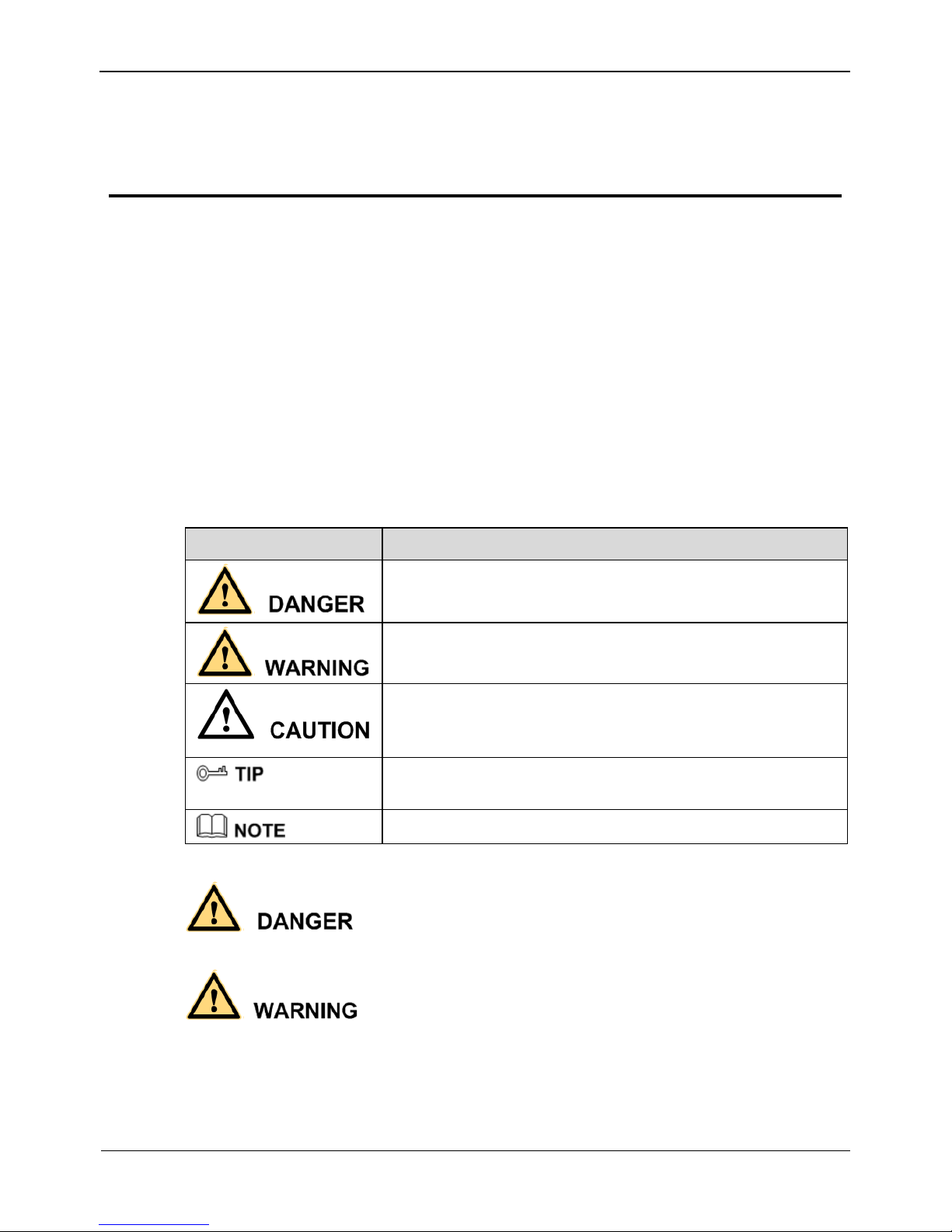
Symbols
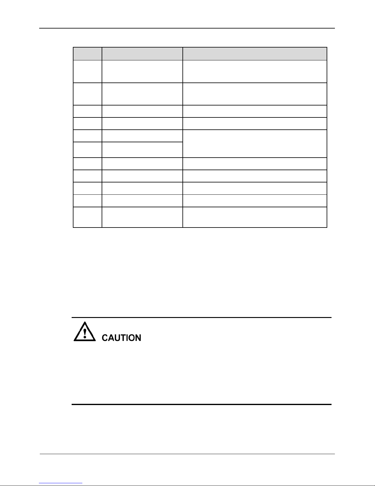
This document may contain the following symbols whose meanings are described
accordingly.
Symbol
Description
It alerts you to fatal dangers which, if not avoided, may
cause deaths or severe injuries.
It alerts you to moderate dangers which, if not avoided,
may cause minor or moderate injuries.
It alerts you to risks. Neglect of these risks may cause
device damage, data loss, device performance
deterioration, or unpredictable results.
It provides a tip that may help you resolve problems or
save time.
It provides additional information.
To prevent electric shocks or other dangers, keep power plugs dry and clean.
Strictly observe installation requirements when installing the device. The
manufacturer shall not be held responsible for device damage caused by users' nonconformance to these requirements.
Page 4
Precautions
Network Video Recorder(NVR)
User Manual
ii Issue V1.0 (2018-05-11)
Strictly conform to local electrical safety standards and use power adapters that are
marked with the LPS standard when installing and using this device. Otherwise,
this device may be damaged.
Use accessories delivered with this device. The voltage must meet input voltage
requirements for this device.
If this device is installed in places with unsteady voltage, ground this device to
discharge high energy such as electrical surges in order to prevent the power supply
from burning out.
When this device is in use, ensure that no water or any liquid flows into the device.
If water or liquid unexpectedly flows into the device, immediately power off the
device and disconnect all cables (such as power cables and network cables) from
this device.
Do not focus strong light (such as lighted bulbs or sunlight) on this device.
Otherwise, the service life of the image sensor may be shortened.
If this device is installed in places where thunder and lightning frequently occur,
ground the device nearby to discharge high energy such as thunder strikes in order
to prevent device damage.
Avoid heavy loads, intensive shakes, and soaking to prevent damages during
transportation and storage. The warranty does not cover any device damage that is
caused during secondary packaging and transportation after the original packaging
is taken apart.
Protect this device from fall-down and intensive strikes, keep the device away from
magnetic field interference, and do not install the device in places with shaking
surfaces or under shocks.
Clean the device with a soft dry cloth. For stubborn dirt, dip the cloth into slight
neutral cleanser, gently wipe the dirt with the cloth, and then dry the device.
Do not jam the ventilation opening. Follow the installation instructions provided in
this document when installing the device.
Keep the device away from heat sources such as radiators, electric heaters, or other
heat equipment.
Keep the device away from moist, dusty, extremely hot or cold places, or places
with strong electric radiation.
If the device is installed outdoors, take insect- and moisture-proof measures to
avoid circuit board corrosion that can affect monitoring.
Remove the power plug if the device is idle for a long time.
Before unpacking, check whether the fragile sticker is damaged. If the fragile
sticker is damaged, contact customer services or sales personnel. The manufacturer
shall not be held responsible for any artificial damage of the fragile sticker.
Page 5

Network Video Recorder(NVR)
User Manual
Precautions
Issue V1.0 (2018-05-11) iii
Special Announcement
All complete products sold by the manufacturer are delivered along with nameplates,
operation instructions, and accessories after strict inspection. The manufacturer shall
not be held responsible for counterfeit products.
This manual may contain misprints, technology information that is not accurate enough,
or product function and operation description that is slightly inconsistent with the
actual product. The manufacturer will update this manual according to product function
enhancement or changes and regularly update the software and hardware described in
this manual. Update information will be added to new versions of this manual without
prior notice.
This manual is only for reference and does not ensure that the information is totally
consistent with the actual product. For consistency, see the actual product.
Page 6

Contents
Network Video Recorder(NVR)
User Manual
iv Issue V1.0 (2018-05-11)
Contents
Precautions .................................................................................................................... i
1 Specifications............................................................................................................ 1
2 Hard Disk .................................................................................................................. 3
2.1 Precautions ..................................................................................................................... 3
2.2 Hard Disk Recommendation .......................................................................................... 3
2.3 Approximate Video Storage Duration ............................................................................. 3
2.4 Hard Disk Installation .................................................................................................... 4
3 Operation Instruction.............................................................................................. 8
3.1 Front panel ..................................................................................................................... 8
3.2 Rear panel....................................................................................................................... 8
3.3 Startup .......................................................................................................................... 10
3.4 Shutdown ...................................................................................................................... 11
3.5 Adjusting the Screen Resolution of the Monitor........................................................... 12
3.6 Login ............................................................................................................................ 13
3.7 Changing password ...................................................................................................... 14
3.8 Adding Webcams .......................................................................................................... 15
4 Quick Setup ............................................................................................................ 16
5 Live Video ............................................................................................................... 20
6 Video Playback....................................................................................................... 25
6.1 Video Playback ............................................................................................................. 25
6.2 Video Backup ............................................................................................................... 26
7 Alarm Search .......................................................................................................... 29
8 Setting ...................................................................................................................... 31
8.1 NVR Setup ................................................................................................................... 31
8.1.1 Device Information .......................................................................................... 31
8.2 Device .......................................................................................................................... 32
8.2.1 Network............................................................................................................ 32
8.2.2 System .............................................................................................................. 34
8.2.3 Device Port ....................................................................................................... 35
8.2.4 Date and Time .................................................................................................. 36
Page 7

Network Video Recorder(NVR)
User Manual
Contents
Issue V1.0 (2018-05-11) v
8.3 Channel ........................................................................................................................ 39
8.3.1 Manage Channel .............................................................................................. 39
8.3.2 Camera Information ......................................................................................... 39
8.3.3 Stream ................................ ................................ ................................ .............. 40
8.3.4 Network............................................................................................................ 44
8.3.5 OSD ................................................................................................................. 46
8.3.6 Privacy Masking .............................................................................................. 49
8.3.7 Motion Alarm ................................................................................................... 50
8.3.8 Intelligence Analyse Alarm .............................................................................. 52
8.3.9 Video Lost Alarm ............................................................................................. 53
8.3.10 Alarm Input .................................................................................................... 55
8.3.11 Camera Maintenance ...................................................................................... 56
8.4 Live Video Layout ........................................................................................................ 56
8.5 Record .......................................................................................................................... 59
8.5.1 Record Policy ................................................................................................... 59
8.5.2 Storage ............................................................................................................. 61
8.6 Network Service ........................................................................................................... 62
8.6.1 DDNS ............................................................................................................... 62
8.6.2 PPPoE .............................................................................................................. 64
8.6.3 SMTP ............................................................................................................... 66
8.6.4 IP Filter ............................................................................................................ 67
8.7 External Device ............................................................................................................ 69
8.7.1 Display screen .................................................................................................. 69
8.8 Alarm ............................................................................................................................ 70
8.8.1 Alarm Input ...................................................................................................... 70
8.8.2 .Alarm Out ....................................................................................................... 70
8.8.3 Disk Alarm ....................................................................................................... 71
8.9 Privilege ....................................................................................................................... 72
8.10 Device Log ................................................................................................................. 76
8.10.1 Alarm Log ...................................................................................................... 76
8.10.2 Operation Log ................................................................................................ 78
8.11 Scheduled Reboot ....................................................................................................... 80
8.12 System ................................ ................................ ................................ ........................ 81
8.13 Maintenance ................................ ................................................................ ............... 82
9 Web Access .............................................................................................................. 84
9.1 Login ............................................................................................................................ 84
9.2 Live Video .................................................................................................................... 85
9.3 Video Playback ............................................................................................................. 85
Page 8

Contents
Network Video Recorder(NVR)
User Manual
vi Issue V1.0 (2018-05-11)
9.4 Alarm Search ................................................................................................................ 86
9.5 NVR Setup ................................................................................................................... 87
10 FAQ ........................................................................................................................ 89
Page 9
Network Video Recorder(NVR)
User Manual
1 Specifications
Issue V1.0 (2018-05-11) 1
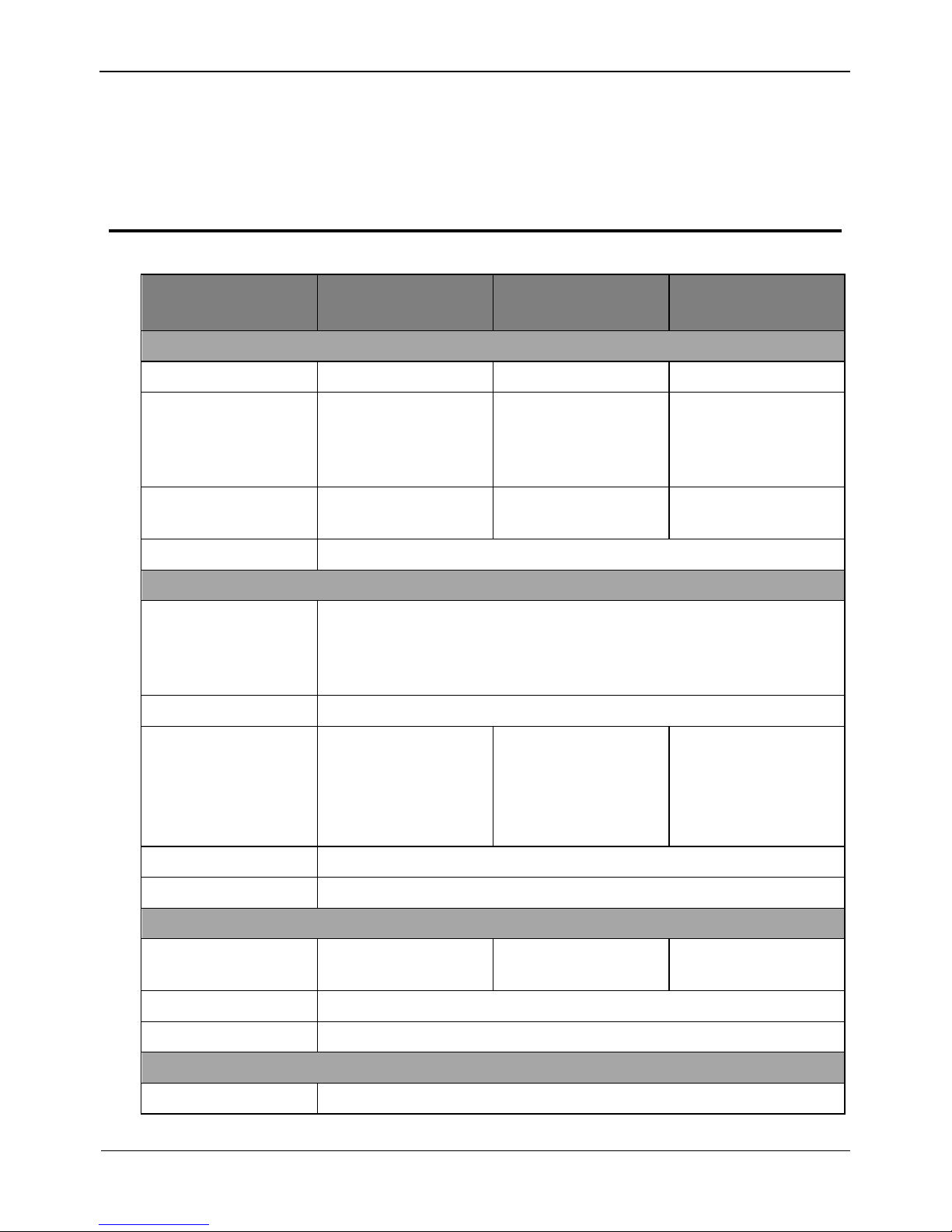
1 Specifications
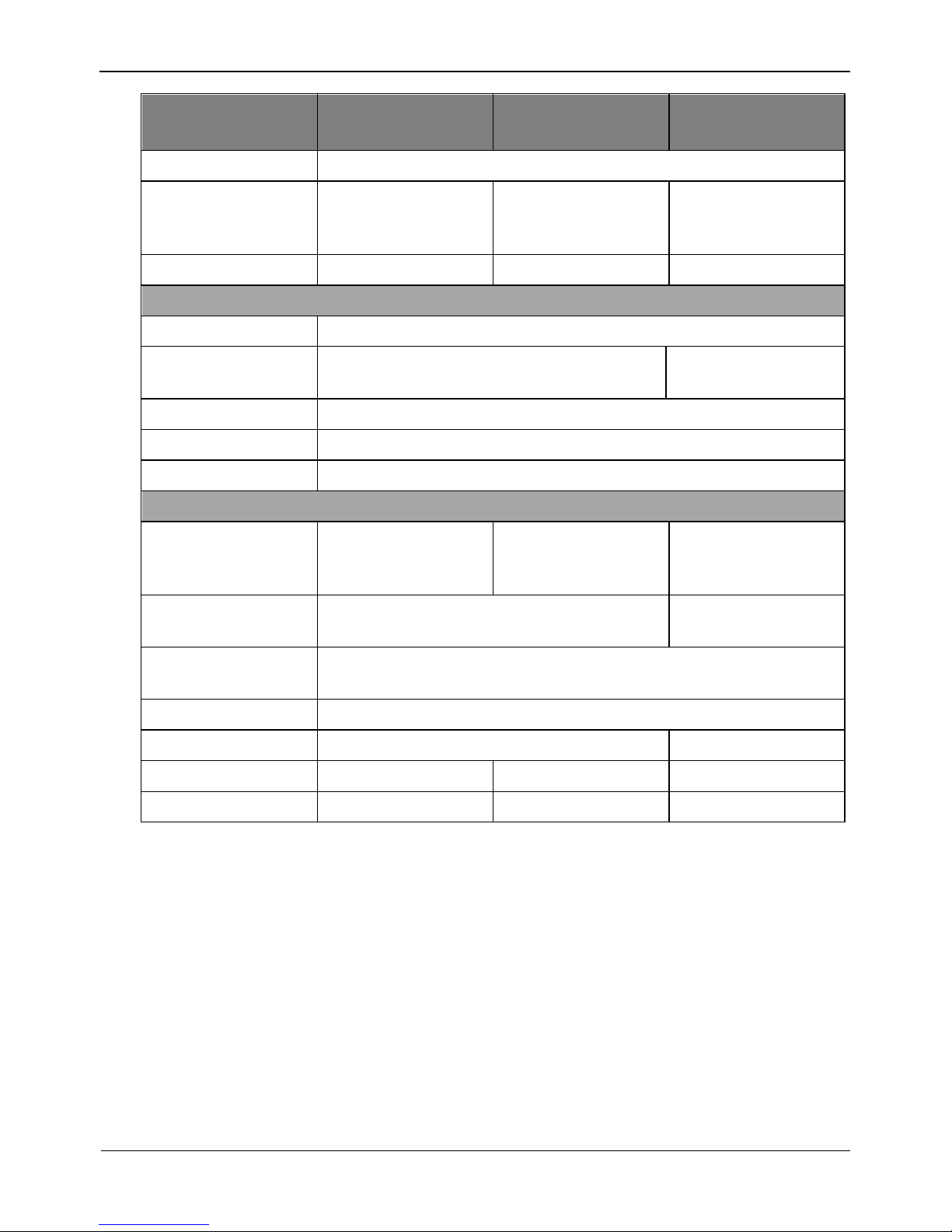
Model
0E-4CHNVR1TB
0E-4CHNVR2TB
0E-8CHNVR2TB
0E-16CHNVR2T
0E-16CHNVR4T
VIDEO/AUDIO INPUT
Video Input
4ch
8ch
16ch
Incoming
Bandwidth
40Mbps ,(main
stream 32Mbps ,sub
stream 8Mbps)
80Mbps ,(main
stream 64Mbps ,sub
stream 16Mbps)
160Mbps ,(main
stream
128Mbps ,sub
stream 32Mbps)
Outgoing
Bandwidth
Total 80Mbps
Total 128Mbps
Total 128Mbps
Audio Input
G711_A/G711_U
VIDEO/AUDIO OUTPUT
Live
View/Playback/
Recording
Resolution
6MP/5MP/4MP/3MP/1080P/960P/720P/D1/VGA/CIF/QCIF
Frame Rate
6MP/5MP/4MP/3MP@15fps; 1080P@30fps
Live View/Playback
Resolution
Live View: 4ch
1080P/1ch
6MP,@30fps
Playback:4ch
1080P/1ch 6MP
Live View: 8ch
D1/4ch 1080P/1ch
6MP,@30fps
Playback: 4ch
1080P/1ch 6MP
Live View: 16ch
D1/4ch 1080P/1ch
6MP,@30fps
Playback:4ch
1080P/1ch 6MP
HDMI/VGA Output
1920x1080/60Hz,1280x720/60Hz,1024x768/60Hz
Audio Output
1ch,Line out
Hard Disk
SATA HDD
1 SATA interface
for 1HDD
2SATA interface for
2HDD
4SATA interface for
4HDD
Mounting Mode
Embedded
Capacity
Up to 6TB for each disk
NETWORK
Network Interface
1 RJ45 10M/100M/1000M network interface
Page 10
1 Specifications
Network Video Recorder(NVR)
User Manual
2
Issue V1.0 (2018-05-11)
Model
0E-4CHNVR1TB
0E-4CHNVR2TB
0E-8CHNVR2TB
0E-16CHNVR2T
0E-16CHNVR4T
Protocol
RTP/RTCP,TCP/UDP,HTTP,DHCP,DNS,NTP
POE Interface
4ch
100Mbps ,IEEE802.
3af
8ch
100Mbps ,IEEE802.
3af
16ch
100Mbps ,IEEE802.
3af
POE Max Power
36W
120W
160W
INTERFACE
HDMI/VGA
1ch HDMI, 1ch VGA
USB
USB 2.0 x2
USB 2.0 x2, USB
3.0 x1
Audio I/O
1ch MIC in,1ch audio line out
Alarm I/O
2ch Alarm output, 2ch Alarm input
Reset Button
Yes
GENERAL
Power Supply
DC48V-DC52V,
Max Input 70W
AC110/220V Max
input180W
AC110/220V,4763Hz ,Max input
300W
Power Consumption
Max 10W(without HDD,USB,POE)
Max 15W(without
HDD,USB,POE)
Operating
Temperature
-10°C ~ 45°C (14°F ~ 113°F )
Operating Humidity
0% - 90% RH
Chassis
Smart 1U
1.5U
Product Dimensions
255x235x47.5mm
372x311x44.5mm
440x376x67mm
Product Weight
930g
2.8kg
4kg
Page 11
Network Video Recorder(NVR)
User Manual
2 Hard Disk
Issue V1.0 (2018-05-11) 3
2 Hard Disk
2.1 Precautions
Formatting will clear all video data on the hard disk. Use this function only when
necessary.
Be sure to uninstall the hard disk before removing it from the NVR during runtime;
otherwise, the hard disk may be damaged or data may be lost.
The NVR must be connected to a stable power supply during runtime; otherwise,
the hard disk may be damaged or data may be lost.
The maximum capacity of a single hard disk cannot exceed 6 TB.
2.2 Hard Disk Recommendation
Seagate or Western Digital hard disks which are highly stable and inexpensive are
recommended.
2.3 Approximate Video Storage Duration
Table 2-1 Approximate Video storage duration
Maximum Hard Disk
Capacity
Maximum Bit Rate
Approximate Video
Storage Duration
1 × 6 TB
18 Mbps
28 days
2×6 TB
36 Mbps
28 days
4 × 6 TB
72 Mbps
28 days
Formulae for calculating the approximate video storage duration:
Step 1 Use the following formula to calculate the storage capacity q (unit: MBybte) required
to record a single video per hour:
q = d/8×3600/1024
Page 12
2 Hard Disk
Network Video Recorder(NVR)
User Manual
4
Issue V1.0 (2018-05-11)
d indicates the bit rate (unit: Kbit/s).
Step 2 Use the following formula to calculate the approximate video storage duration t (unit:
day)
w indicates the capacity (unit: Mbyte) of a single hard disk.
n indicates the number of disks.
h indicates the recording duration per day.
c indicates the number of video inputs of the NVR.
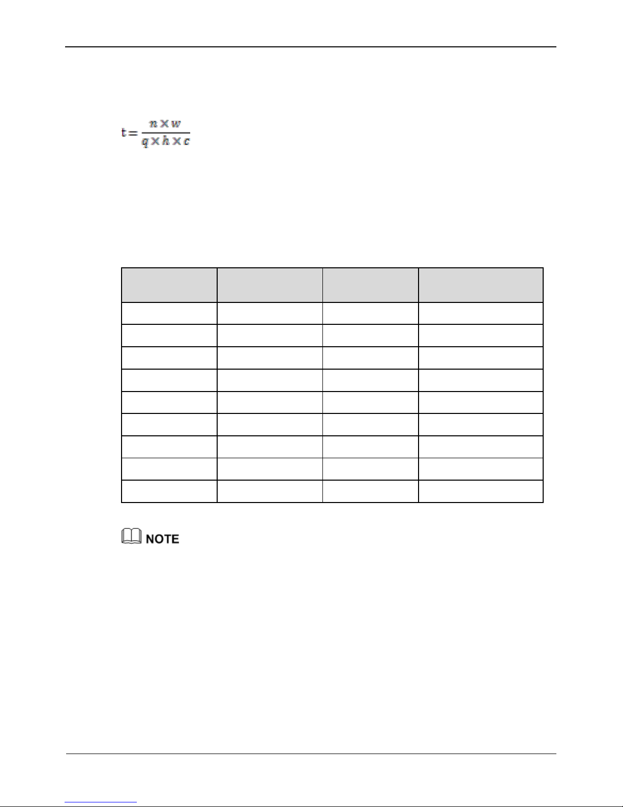
Table 2-2 shows examples of approximate video storage duration (h is 24 hours).
Table 2-2 Examples of approximate video storage duration
Hard Disk
Capacity
Bit Rate
Video Count
Approximate Video
Storage Duration
1×6TB
D1, 1.5Mbps
4
85 days
1×6TB
720p, 3Mbps
4
47 days
1×6TB
1080p, 4.5Mbps
4
28 days
2×6TB
D1, 1.5Mbps
8
85 days
2×6TB
720p, 3Mbps
8
47 days
2×6TB
1080p, 4.5Mbps
8
28 days
4×6TB
D1, 1.5Mbps
16
85 days
4×6TB
720p, 3Mbps
16
47 days
4×6TB
1080p, 4.5Mbps
16
28 days
The data listed in the preceding table is only for your reference. The recording time estimate
may be different from the actual recording time. The user shall be liable for any loss
incurred as a result thereof.
2.4 Hard Disk Installation
Take the following steps to install a hard disk:
Step 1 Unscrew the four fixing screws on both sides and one fixing screw on the back, then
remove the upper cover, as shown in Figure 2-1.
Page 13
Network Video Recorder(NVR)
User Manual
2 Hard Disk
Issue V1.0 (2018-05-11) 5
Figure 2-1 Removing the upper cover
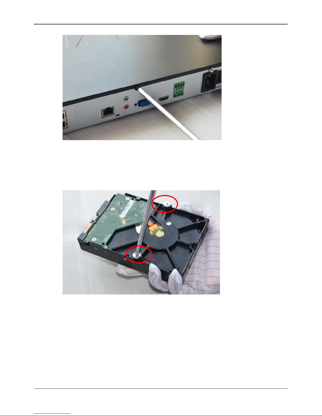
Step 2 Take out the hard disk fixing screws and silicone cushion included in the accessory
package, route the fixing screw through the silicone cushion, and install it to the screw
holes, as shown in Figure 2-2.
Figure 2-2 Installing the hard disk fixing screw
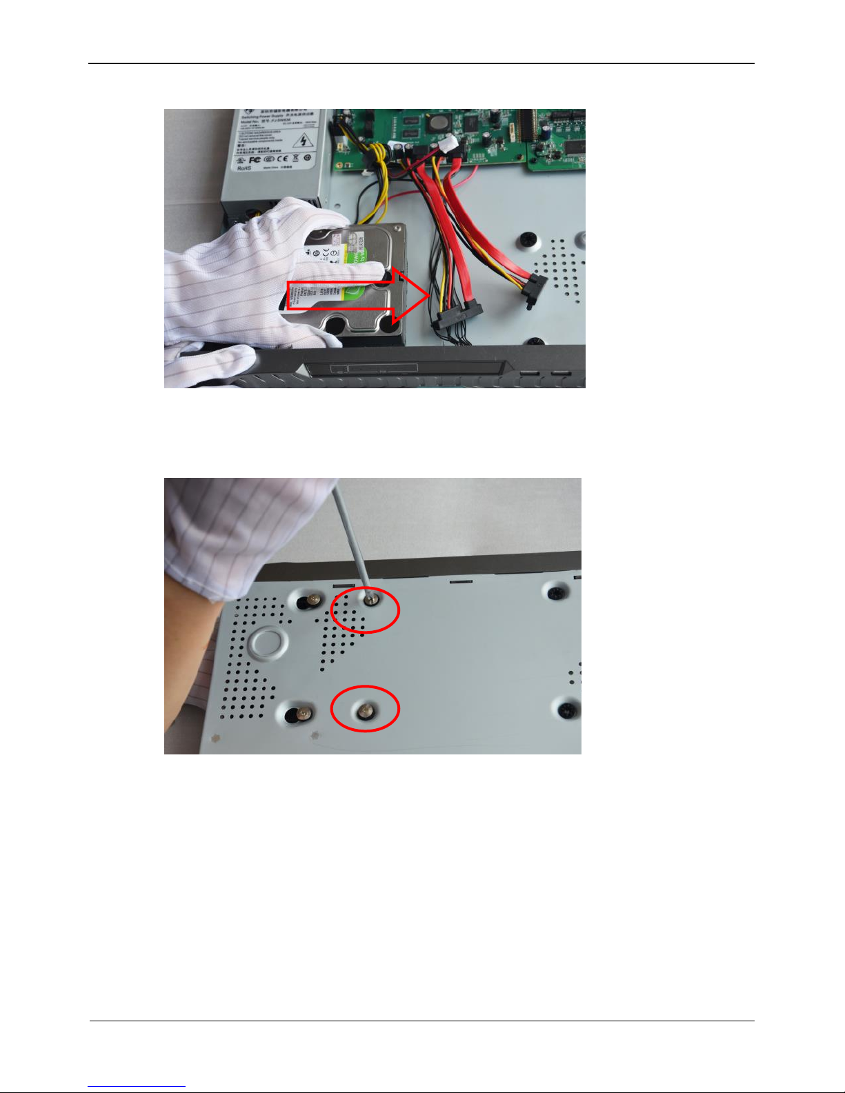
Step 3 Route the hard disk fixing screws through the holes on the base, push the hard disk to
the appropriate position according to the direction of arrow, as shown in Figure 2-3.
Page 14
2 Hard Disk
Network Video Recorder(NVR)
User Manual
6
Issue V1.0 (2018-05-11)
Figure 2-3 Inserting the hard disk
Step 4 Turn the device over, and fasten two hard disk fixing screws, as shown in Figure 2-4.
Figure 2-4 Fixing the hard disk
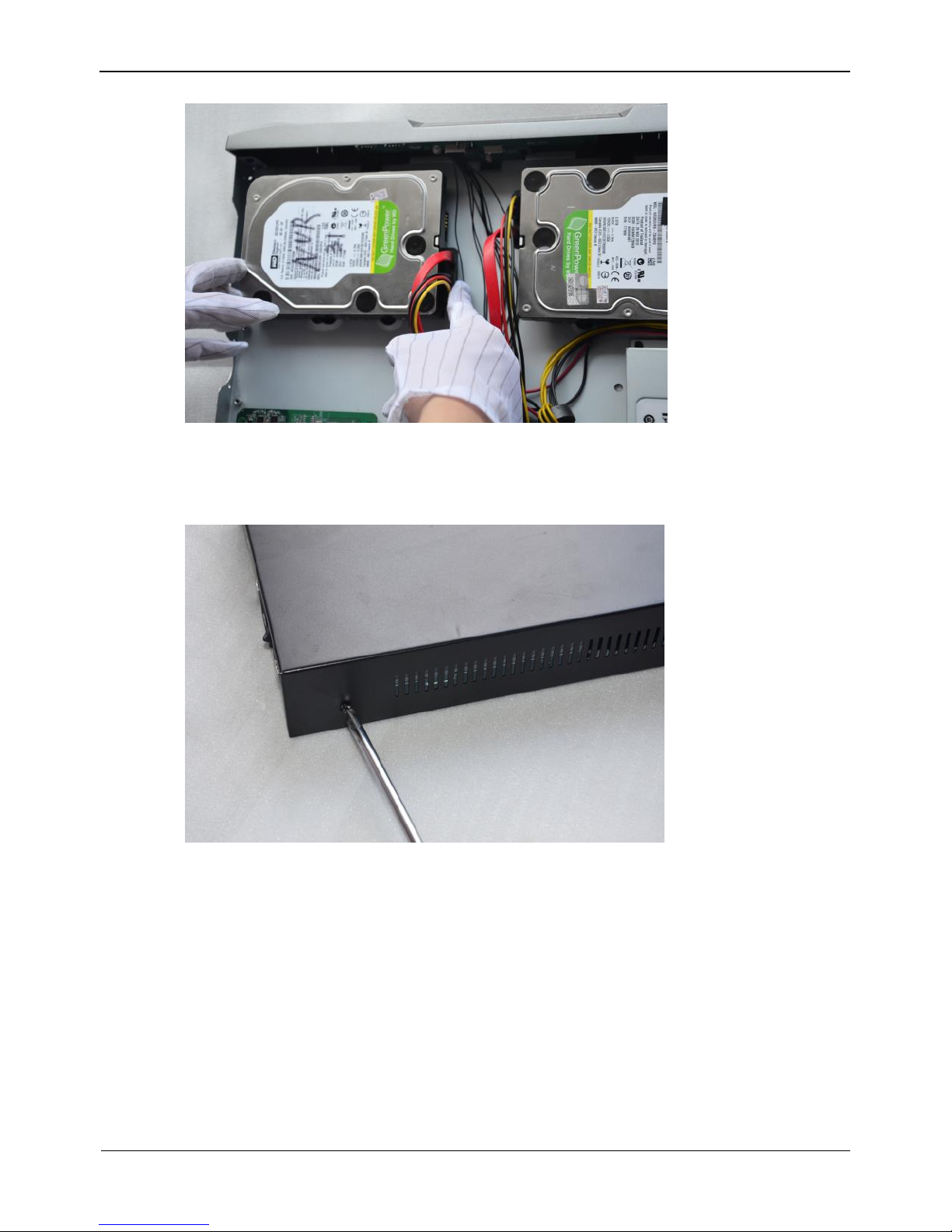
Step 5 Install the other hard disk according to Step 2, Step 3, and Step 4, then insert the hard
disk data cable and power cable, as shown in Figure 2-5.
Page 15
Network Video Recorder(NVR)
User Manual
2 Hard Disk
Issue V1.0 (2018-05-11) 7
Figure 2-5 Inserting the cable
Step 6 Put on the upper cover, and fasten the fixing screws, as shown in Figure 2-6.
Figure 2-6 Put on the upper cover
----End
Page 16
3 Operation Instruction
Network Video Recorder(NVR)
User Manual
8
Issue V1.0 (2018-05-11)
3 Operation Instruction
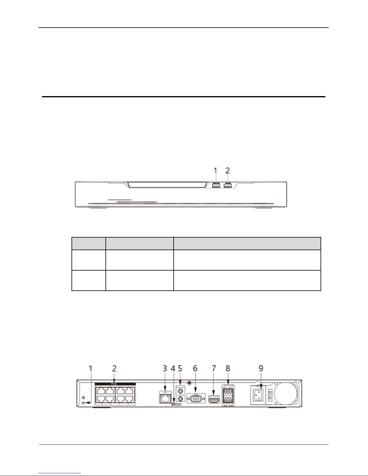
3.1 Front panel
Figure 3-1 shows the front panel of NVR. Table 3-1 shows the description of front
panel.
Figure 3-1 Front panel
Table 3-1 Elements of the front panel
NO.
Element
Description
1
KB/MOUSE
Supports connection to a USB mouse and
keyboard.
2
BACKUP
Supports connection to a USB flash drive or
USB removable hard disk.
3.2 Rear panel
Figure 3-2 shows the rear panel of 0E-8CHNVR2TB and the interfaces on it.
Figure 3-2 Rear panel of 0E-8CHNVR2TB
Page 17
Network Video Recorder(NVR)
User Manual
3 Operation Instruction
Issue V1.0 (2018-05-11) 9
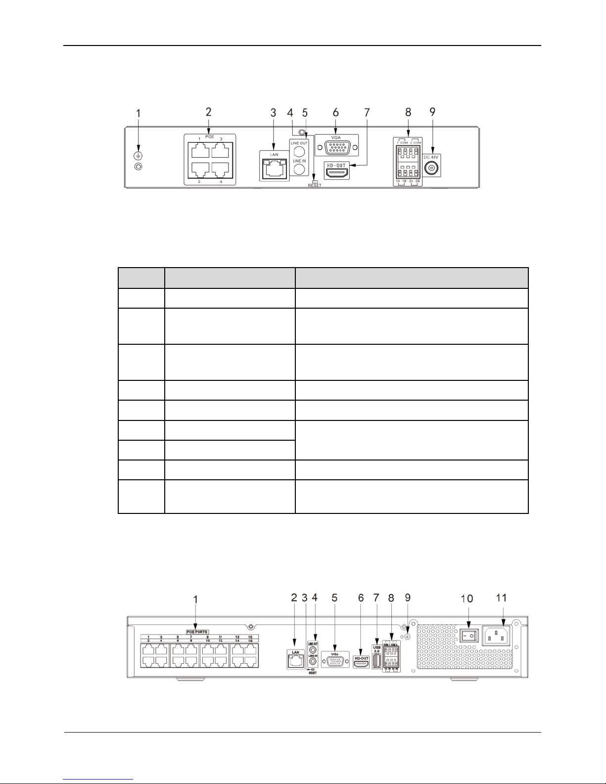
Figure 3-3 shows the rear panel of 0E-4CHNVR1TB & 0E-4CHNVR2TB and the
interfaces on it.
Figure 3-3 Rear panel of 0E-4CHNVR1TB & 0E-4CHNVR2TB
Table 3-2 shows the description of rear panel of 0E-8CHNVR2TB, 0E-4CHNVR1TB
& 0E-4CHNVR2TB.
Table 3-2 Elements of the real panel
NO.
Name
Description
1
Ground screw
Safe ground screw of the device
2
PoE network
interface
PoE network interfaces
3
LAN
RJ45 10 /100/1000 Mbps adaptive
Ethernet interface
4
Reset
Factory reset button
5
Line In/ Line Out
Audio input/ Audio output
6
VGA
Video output interface
7
HD-OUT
8
Alarm In/Out
2 alarm input, 2 alarm output
9
Power interface
AC 110V/220V power input interface of the
device
Figure 3-3 shows the rear panel of 0E-16CHNVR2T & 0E-16CHNVR4T and the
interfaces on it.
Table 3-3shows the description of rear panel of 0E-16CHNVR2T & 0E-16CHNVR4T.
Page 18
3 Operation Instruction
Network Video Recorder(NVR)
User Manual
10 Issue V1.0 (2018-05-11)
Table 3-3 Elements of the real panel of 0E-16CHNVR2T & 0E-16CHNVR4T
NO.
Name
Description
1
PoE network
interface
PoE network interfaces
2
LAN
RJ45 10 /100/1000 Mbps adaptive
Ethernet interface
3
Reset
Factory reset button
4
Line In/ Line Out
Audio input/ Audio output
5
VGA
Video output interface
6
HD-OUT
7
USB 3.0
Connect to mobile storage devices
8
Alarm In/Out
2 alarm input, 2 alarm output
9
Ground screw
Safe ground screw of the device
10
Power switch
--
11
Power interface
AC 110V/220V power input interface of the
device
3.3 Startup
Before starting the NVR, ensure that the NVR is connected to a power supply.
When the NVR is connected to a power supply, it starts automatically upon the initial
power-on.
Ensure that a power supply is connected to the NVR correctly.
Before starting the NVR, ensure that a monitor is connected to the HDMI or VGA
interface of the NVR correctly.
The NVR may not operate normally when a power supply exception occurs, likely
causing damage to the NVR in serious conditions. In such a circumstance, you are
advised to use a regulated power supply.
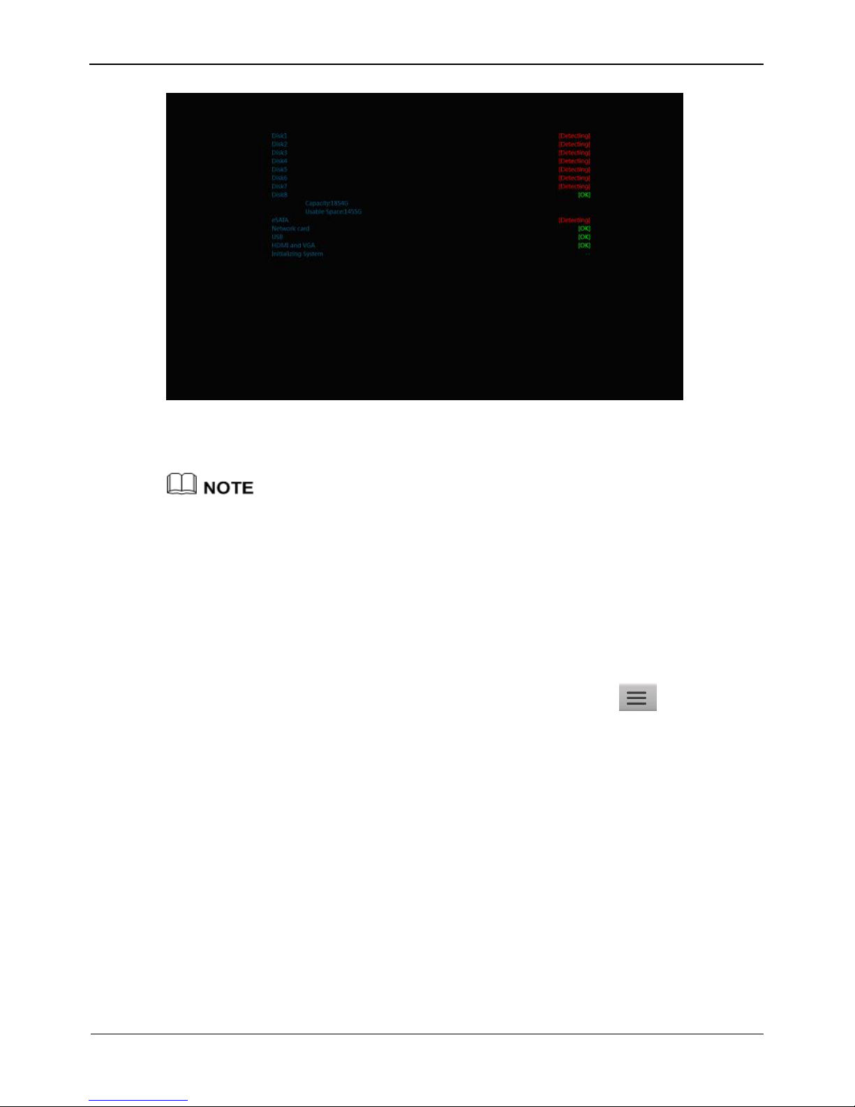
When the NVR is started, the power indicator becomes steady on and the NVR starts a
self-test and displays the test result on the screen, as shown in Figure 3-4.The startup
process takes about 2 minutes.
Page 19
Network Video Recorder(NVR)
User Manual
3 Operation Instruction
Issue V1.0 (2018-05-11) 11
Figure 3-4 NVR self-test
When the hardware abnormality is detected, the self-test screen stays on. You can click
continue or shutdown in the lower right corner of the screen. If you click continue,
the NVR enters the login screen.
The hard disk of the NVR must be provided by the user. Hard disk detection is performed
during startup. If the detection fails, possible causes include:
The hard disk is new and unformatted. The hard disk is formatted, but the file system is
inconsistent with the one supported by the NVR.
The hard disk is damaged.
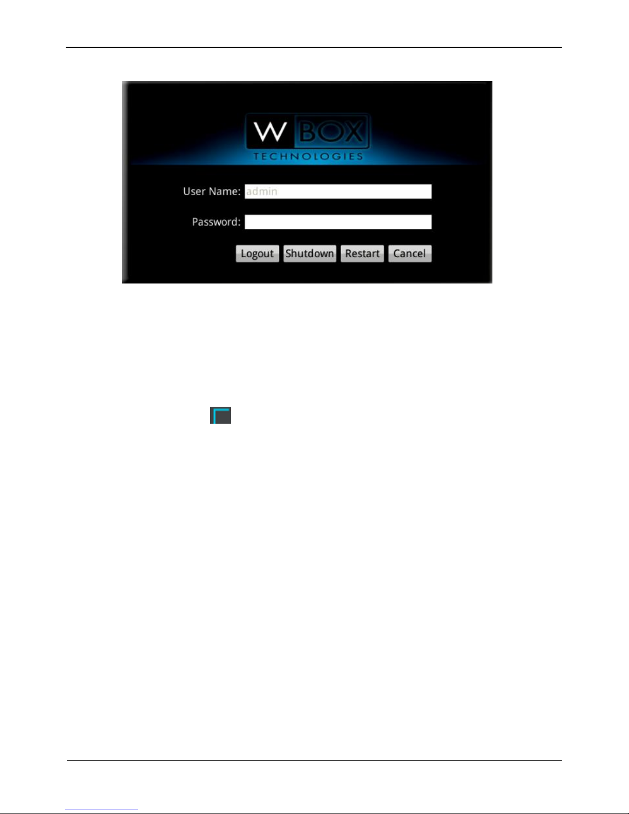
3.4 Shutdown
To shut down the NVR after logging in to the main interface, click and choose
Exit System in the upper right corner. The shutdown interface appears, as shown in
Figure 3-5.
Page 20
3 Operation Instruction
Network Video Recorder(NVR)
User Manual
12 Issue V1.0 (2018-05-11)
Figure 3-5 Shutdown interface
Enter the correct password and click Shutdown. When authentication is successful, the
shutdown successful page is displayed, then cut off the power.
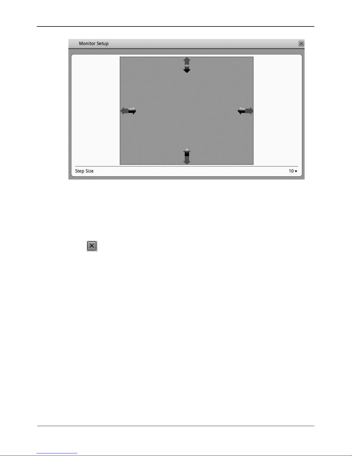
3.5 Adjusting the Screen Resolution of the Monitor
You need to adjust the display of the monitor in the case of incomplete or skewed
display (the icon in the four corners of the screen is out of view). (You are
advised to use the automatic adjustment function of the monitor first.)
Take the following steps to adjust the screen resolution of the monitor:
Step 1 Click Adjust in the lower left corner, the Monitor Setup interface appears, as shown
in Figure 3-6.
Page 21
Network Video Recorder(NVR)
User Manual
3 Operation Instruction
Issue V1.0 (2018-05-11) 13
Figure 3-6 Monitor Setup interface
Step 2 Select a step from the Step Size dropdown list.
Step: is the distance the screen moves during each adjustment. The greater the value is,
the longer the distance of movement. First select a large step for rough adjustment and
then select a small step for fine adjustment.
Step 3 Use the up, down, left, and right arrows on the interface to adjust the screen.
Step 4 Click in the upper right corner of the Monitor Setup interface to exit the Monitor
Setup interface and return to the login interface.
3.6 Login
Take the following steps to log in to the NVR:
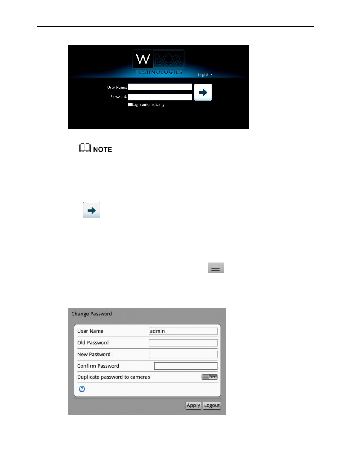
Step 1 Enter your user name and password on the login interface of the NVR, as shown in
Figure 3-7.
Page 22
3 Operation Instruction
Network Video Recorder(NVR)
User Manual
14 Issue V1.0 (2018-05-11)
Figure 3-7 Login interface of the NVR
The superuser is admin and the password is also admin, both of which are case-sensitive.
Change the password after logging in to the NVR for the first time.
When a user enters incorrect passwords three times in a low during login, the account is
locked. And the account is unlocked after 5 minutes.
The superuser admin cannot be locked.
Step 2 Click to enter the main interface.
----End
3.7 Changing password
Step 1 When login in the NVR for the first time, or click and choose Change
Password in the upper right corner, the change password interface appears, as shown
in Figure 3-8
Figure 3-8 Change password interface of the NVR
Page 23
Network Video Recorder(NVR)
User Manual
3 Operation Instruction
Issue V1.0 (2018-05-11) 15
The change password page will be displayed if you don’t change the default password when
you login the system for the first time.
Step 2 Enter the old password, new password, and confirmation password.
Step 3 Click Apply.
If the message "Modify success" is displayed, click OK, the NVR restarts and the
password is successfully changed. If the password fails to be changed, the cause is
displayed. (For example, the new password length couldn’t be less than eight.)
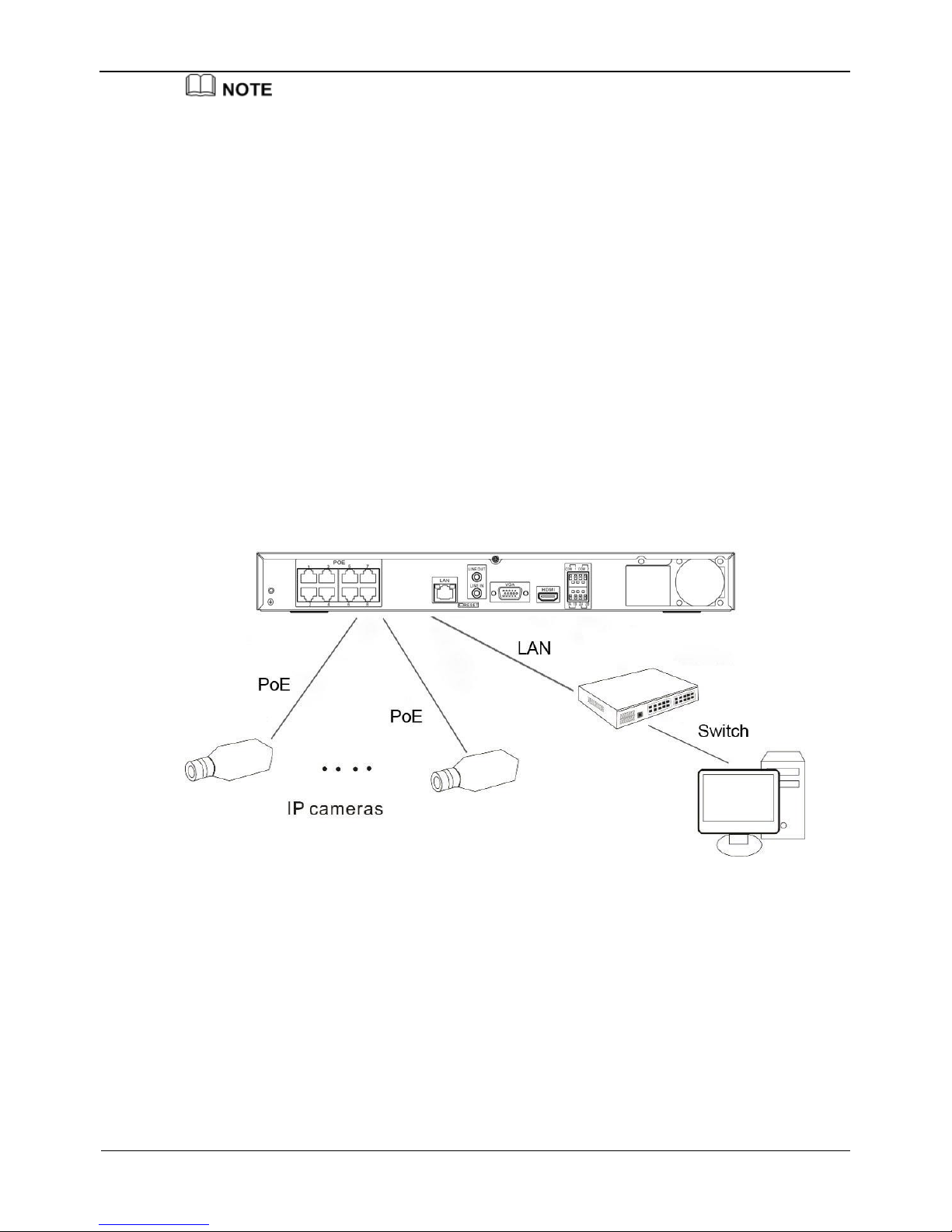
3.8 Adding Webcams
PoE
After the PoE network interfaces are connected to IP cameras, the NVR automatically
adds the IP cameras.
Figure 3-9 shows the network topology of 2 HDD& 8 channels NVR.
Figure 3-9 Network topology of the NVR
---End
Page 24
4 Quick Setup
Network Video Recorder(NVR)
User Manual
16 Issue V1.0 (2018-05-11)
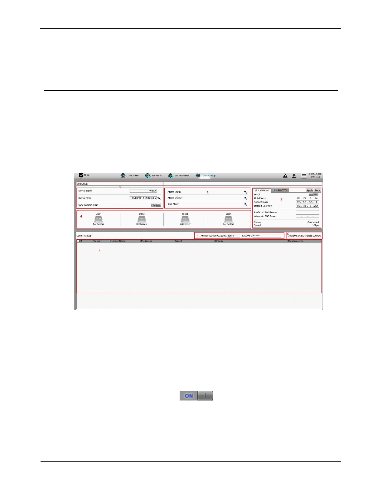
4 Quick Setup
Quick setup provide NVR basic information configuration, NVR network
configuration, alarm configuration, disk management, time setting, IP camera search,
video configuration, camera network configuration, stream configuration, and mobile
detection configuration.
Figure 4-1 shows the quick setup screen.
Figure 4-1 Quick setup screen
Description
1. NVR basic information and time synchronization
Basic information of the NVR
You can set the name and system time of the NVR.
Time synchronization of IP cameras.
The default value is ON. click to close time synchronization.
2. Alarm configuration
NVR alarm configuration contains Alarm Input, Alarm Output and disk Alarm. For
how to set alarm see 8.8 Alarm.
3. NVR network configuration
Page 25
Network Video Recorder(NVR)
User Manual
4 Quick Setup
Issue V1.0 (2018-05-11) 17
The default IP address of the NVR is: 192.0.0.64.
You can enable automatic IP address acquisition and set the IP address, DNS
address of the NVR, and display the network connection status and speed.
4. Hard disk management
Formatting will clear all video data on the hard disk. Use this function only when
necessary.
Be sure to uninstall the hard disk before removing it from the NVR during runtime;
otherwise, the hard disk may be damaged or data may be lost.
The NVR must be connected to a stable power supply during runtime; otherwise,
the hard disk may be damaged or data may be lost.
You can manage the hard disk of the NVR as follows:
Format the hard disk. Click Format. In the displayed dialog box, click Yes.
Check the used space and total space of the hard disk.
5. Authentication accounts of managed cameras
Only successfully authenticated cameras can be used normally. Before adding a camera,
add the authentication account and password of the camera to the list.
To log in to an IP camera, you need to enter the correct authentication account. Only
successfully authenticated IP cameras can be managed. Double-click the user name and
password text field to modify the user name and password
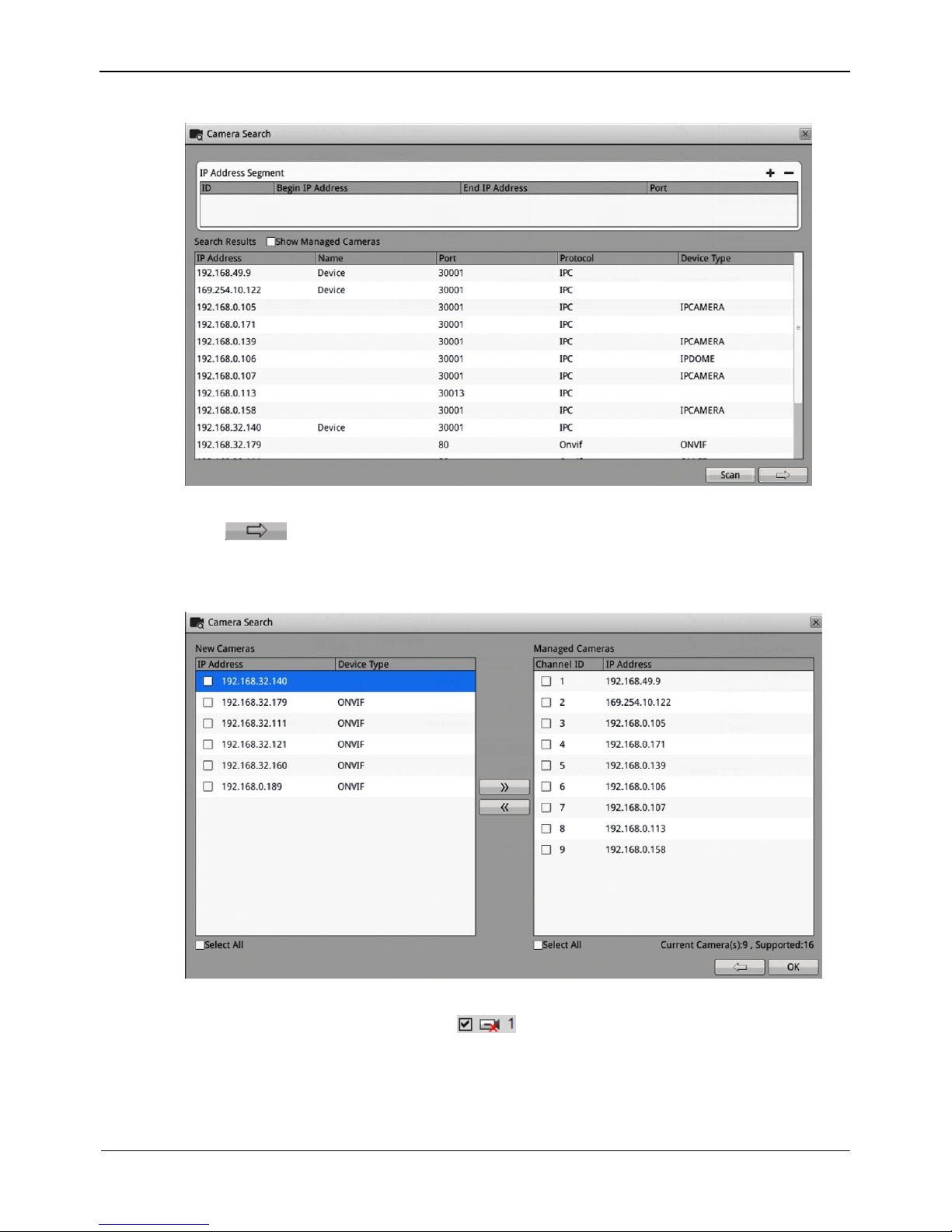
6. Camera search and deletion
When you need to search camera for management, click Search Camera, the Camera
Search interface is displayed, then click Scan, it will scan for the camera automatically,
as shown in Figure 4-2.
Page 26
4 Quick Setup
Network Video Recorder(NVR)
User Manual
18 Issue V1.0 (2018-05-11)
Figure 4-2 Camera searching page
Click , the camera select interface is displayed as shown in Figure 4-3. Select
the cameras you want and then click OK to complete selection of IP cameras.
Figure 4-3 Camera selecting page
To remove managed cameras, click in the camera list, select the cameras to
be removed, and click Delete Camera.
6. IP camera setup
You can view the status of an IP camera and set the name, IP address, recording policy,
stream parameter, and motion detection parameter of the IP camera.
Page 27
Network Video Recorder(NVR)
User Manual
4 Quick Setup
Issue V1.0 (2018-05-11) 19
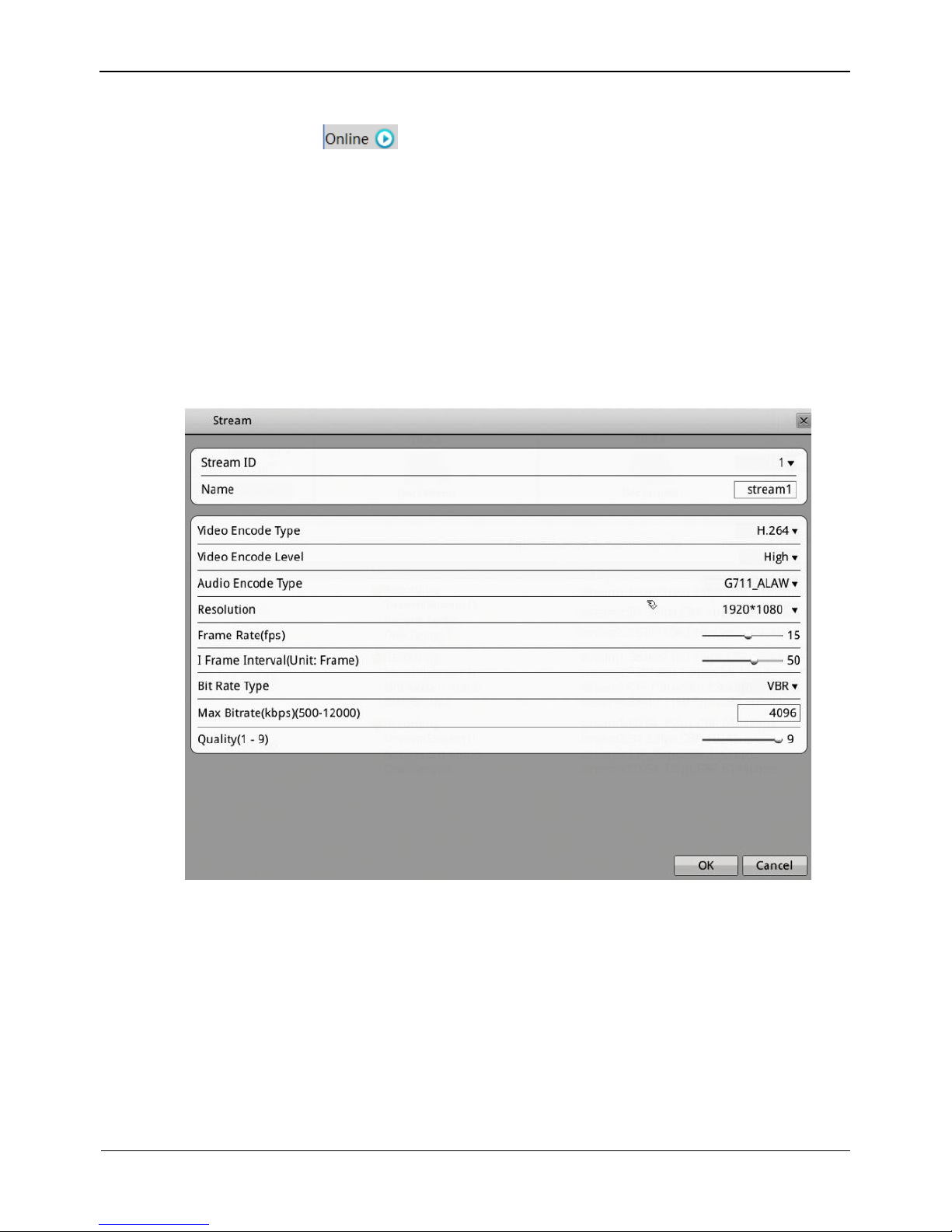
Viewing the status of an IP camera
The camera status may be Online, Offline, and Incorrect account. For an online IP
camera, click to view live video.
Changing the channel name
Click the channel and enter a new channel name in the Name text field.
Setting a recording policy
Click the recording policy to be modified. The Recording Policy Configuration
interface is displayed. For how to set a recording policy, see 8.5.1 “Record Policy”.
Setting a stream
Click the stream to be modified. The Stream interface is displayed, as shown in Figure 4-4.
Figure 4-4 Stream page
Set stream parameters, and click OK. The parameter settings are applied to selected
IP cameras.
Setting a motion detection alarm
Click the motion detection information to be modified. The Motion Alarm page is
displayed. Set the arming time and detection zone when the motion detection alarm
function is enabled. For how to set a motion alarm detection, see 8.5.1 “Record
Policy”.
----End
Page 28
5 Live Video
Network Video Recorder(NVR)
User Manual
20 Issue V1.0 (2018-05-11)
5 Live Video
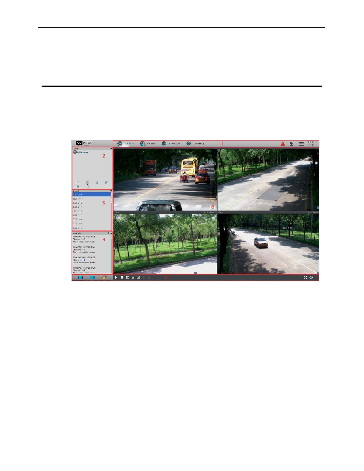
Enter your user name and password on the login interface and click Login.
The Live Video interface appears, as shown in Figure 5-1.
Figure 5-1 Live Video interface
On the Live Video interface, drag a camera in the Cameras pane on the left to the live
channel and perform the following operations:
Live video playing
Alarm viewing
Record status viewing
PTZ control
Audio listening
Automatic full screen
Video bookmark
Front-end parameter setting
Decoding capability
When the video to be played exceeds the supported decoding capability, the video pane
prompts insufficient decoding capability.
Page 29
Network Video Recorder(NVR)
User Manual
5 Live Video
Issue V1.0 (2018-05-11) 21
Intelligent code stream adaptation
The system provides an intelligent code stream adaptation mechanism.
When a video is played, the system selects a proper code stream based on the sizes and
number of video windows and its own decoding capability to achieve optimal real-time
surveillance effect.
To change a code stream manually, right-click and select a new code stream among the
ones supported by the video device from the Stream option in the shortcut menu. Code
stream information is displayed at the bottom of the video pane.
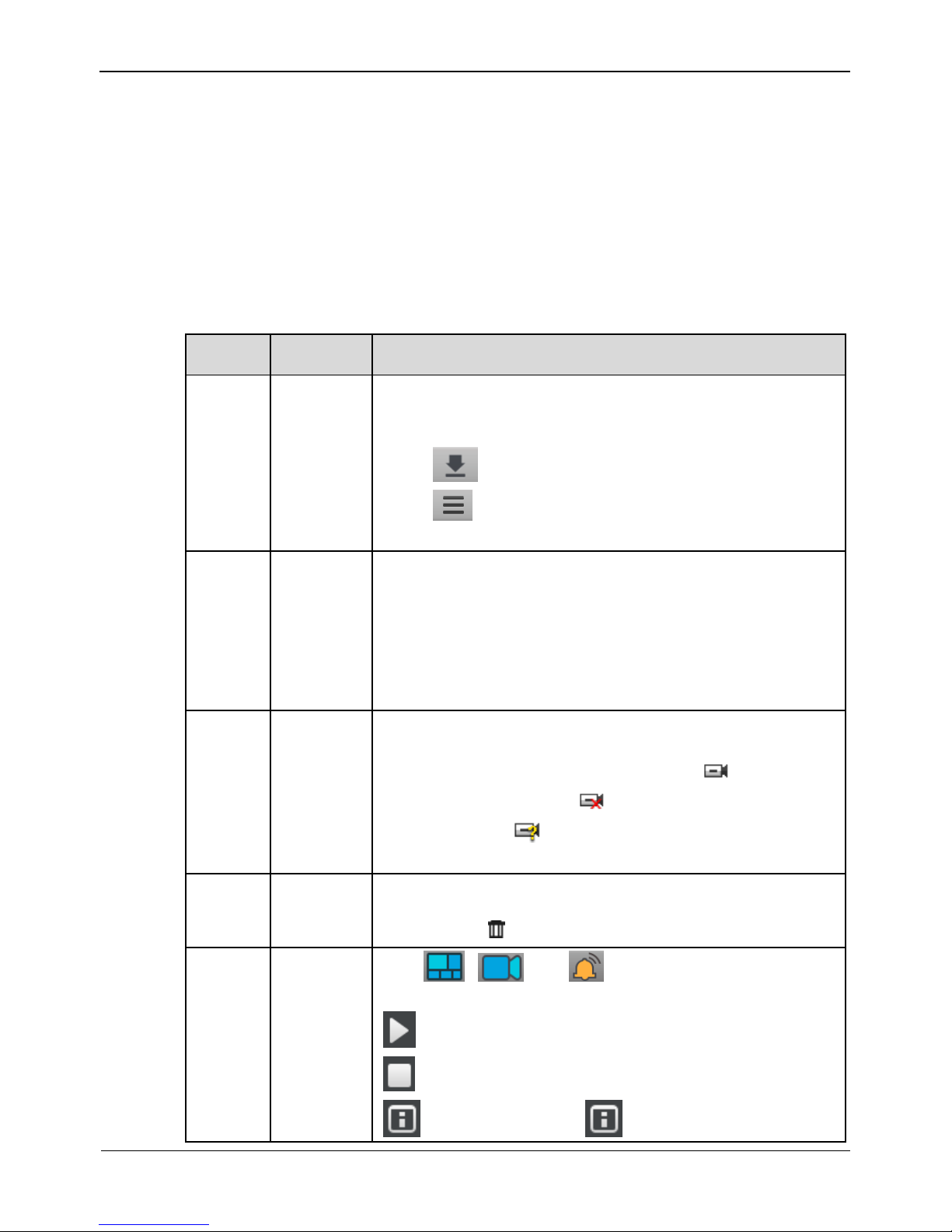
Table 5-1 lists the elements of the Live Video interface.
Table 5-1 Elements of the Live Video interface
No.
Name
Description
1
Top menu
The top menu includes Live Video, Playback, Alarm
Search, and Quick Setup. Click each one to enter the
corresponding operation interface.
Click to enter the record backup interface.
Click to set NVR setup, change language, lock NVR,
change password or exit system.
2
Layouts
pane
To play a live video, select the one-screen, four-screen, or
eight-screen layout and drag a camera in the Cameras pane
to the layout window. To save a layout, click Save in the
control bar at the bottom of the interface and select Shared
Layout or My Layout as the save location. The camera
sequencing layout is supported and can be set in Layouts of
NVR Setup.
3
Cameras
pane
The Cameras pane shows all cameras managed by the
system. To play a live video, drag a camera to the layout
window. Online cameras are marked with ; offline
cameras are marked with ; non-authenticated cameras
are marked with (the entered user name or password is
incorrect).
4
Alarm
Info pane
The Alarm Info pane displays the latest 20 camera alarms,
including motion detection alarms and I/O alarms. To clear
alarms, click .
5
Bottom
menu
Click , , and to hide or show the Layouts,
Cameras, and Alarm Info panes.
: used to play a live video.
: used to close a live video.
:Show all titles.Click to hide all titles and the
Page 30
5 Live Video
Network Video Recorder(NVR)
User Manual
22 Issue V1.0 (2018-05-11)
No.
Name
Description
icon becomes .
:Open stretch. Click to close stretch and the
icon becomes .
:Open fluency pattern. Click to close fluency
pattern and the icon becomes .
: The PTZ control menu appears when you click this
button.
: Save layout, It is valid when create a layout and
change a layout.
6
Live
Video
pane
This pane plays live videos and provides the front-end
parameter setting function.
To change a code stream manually, right-click and select a
new code stream among the ones supported by the video
device from the Stream option in the shortcut menu. Code
stream information is displayed at the bottom of the video
pane.
Automatic full screen
Click and choose whether to enable automatic full screen and the delay time to
enable automatic full screen in the shortcut menu. If automatic full screen is enabled,
the full screen is displayed when no operation is performed during the delay time.
A toolbar appears when you move the cursor to the bottom of the full screen. To exit the
full screen, click in the toolbar.
To enter the full screen mode manually, click .
PTZ operation
All PTZ functions are only available to High Speed Network Dome and device
connected to an external PTZ.
Click . The PTZ operation menu appears, as shown in Figure 5-2. The following
items can be configured: PTZ direction, zoom, preset position, track, scanning, home
position, infrared lamp, true north, and timer.
Page 31

Network Video Recorder(NVR)
User Manual
5 Live Video
Issue V1.0 (2018-05-11) 23
Figure 5-2 PTZ control menu
In the PTZ control area, you can perform the following operations:
Slide the slider left or right beyond the PTZ rotation keys, you can adjust the PTZ
rotation speed.
Click the arrows on the to move the PTZ in eight directions.
Click or to adjust the focal length.
Click or to adjust the aperture.
Click or to focus.
Click to set due north direction.
Click to enable automatic prime function.
In the PTZ configure area, you can perform the following operations:
The PTZ control menu takes effect only for high-speed domes and external PTZ cameras.
To close the PTZ setup menu, click on the PTZ control interface.
To exit the PTZ control menu, click on the PTZ control interface.
Page 32

5 Live Video
Network Video Recorder(NVR)
User Manual
24 Issue V1.0 (2018-05-11)
Add, delete, and invoke preset positions.
Add, delete, and invoke tracks.
Add, delete, and invoke scans.
Add, delete, and invoke tours.
Set the idle.
Set the timer.
Set the extension.
Set Light On/Off and Brush function.
Brush is used to clean the lens. Light On/Off is used to control the infrared camera
shields on and off.
Brush is available only to a camera with a brush or a camera shield.
Light On/Off is available only to specific camera shields.
Quick operation on the Live Video interface
Right-click the mouse button and the Live Video menu appears (shown in Figure 5-3),
where you can choose to bookmark record, sensor, interphone and stream information.
Figure 5-3 Live Video menu
----End
Page 33

Video Playback
Network Video Recorder(NVR)
User Manual
Issue V1.0 (2018-05-11) 25
6 Video Playback
6.1 Video Playback
Video playback refers to playing of videos stored in local hard disks, as shown in
Figure 6-1.
Figure 6-1 Local video playback
Take the following steps to play a video:
Step 1 Select a camera.
Click a camera in the Cameras pane. A selected camera is marked with . An
unselected camera is marked with .
Step 2 Select a date.
Select a date in the Date pane. Click and to change months or click and
to change years. indicates the selected date. The green color indicates that
there are videos captured on that day.
Step 3 Display videos.
After a camera and date are selected, video information is displayed below the video
pane. The time scale above the file axis shows the different time points of video
recording. The time in blue in the middle is the time of the video being played. The file
Page 34

6 Video Playback
Network Video Recorder(NVR)
User Manual
26 Issue V1.0 (2018-05-11)
axis displays videos. Reserved videos are in blue, alarm videos are in red, bookmarked
videos are in yellow, and ordinary videos are in green.
: Enter a time point in the Focus time field and click .
Then the video corresponding to the specified time is played.
: provides the time options of 15 minutes, 30 minutes, 1 hour,
4 hours, 8 hours, 12 hours, and 1 day.
If 1 hour is selected, the time span from the first blue column to the last blue column is
1 hour.
Step 4 Play a video.
You can play a video after selecting a camera and date. Figure 6-2 shows the control
bar of video playback.
Figure 6-2 Control bar
When a video is being played, drag the video information bar in the video pane horizontally
to control video playback. To switch to the full screen, click .
----End
6.2 Video Backup
Step 1 Set a backup path.
Click in the upper right corner of the Playback interface. The Backup Tasks
interface appears. Click . The Backup Path Browse dialog box appears, as shown
in Figure 6-3.
Page 35

Video Playback
Network Video Recorder(NVR)
User Manual
Issue V1.0 (2018-05-11) 27
Figure 6-3 Backup path browse dialog box
The Backup Path bar displays the selected backup path. If it is empty, select a backup
path. The list below shows available backup storage devices. The NVR supports two
types of backup storage device, that is, USB storage device and ESATA Disk.
USB Disk
Connect a USB flash drive or mobile hard disk to the USB interface on the front
panel.
The NVR detects and displays the USB disk automatically.
Right-click the USB flash drive and choose Popup or Format to perform the
corresponding operation.
Double-click the USB flash drive to access the corresponding path list, select a
backup path, and click OK to save the setting and exit.
ESATA Disk
Connect a ESATA flash drive or mobile hard disk to the ESATA interface.
The NVR detects and displays the ESATA storage device automatically.
Double-click the ESATA flash drive to access the corresponding path list, select a
backup path, and click OK to save the setting and exit.
Step 2 Set backup file options.
Record File Size: specifies the maximum size of a single backup file.
Record File Type: specifies the type of record file.
Step 3 Select the video to be backed up.
Method 1: Select the video to be backed up during video playback. Figure 6-4 shows
the video backup control bar.
Page 36

6 Video Playback
Network Video Recorder(NVR)
User Manual
28 Issue V1.0 (2018-05-11)
Figure 6-4 Video backup control bar
Select channels of NVR to backup.
Click Select in the video backup control bar to select a video segment.
Select the video file to be backed up (the selected video segment is highlighted in
blue in the display area), click and hold the left mouse button, and drag the cursor
horizontally to select the video file segment to be backed up.
Click Backup to back up the video.
Method 2: Click Backup on the Alarm Search interface when an alarm video is
played.
Step 4 View the file backup progress.
The Backup Tasks interface displays the statuses of backup tasks. A task in progress is
marked with . A task to be done is marked with . A stopped task is marked with .
A failed task is marked with . A completed task is marked with .
Step 5 Search for a video backup file.
Access the backup folder to view completed backup files.
----End
Page 37

Alarm Search
Network Video Recorder(NVR)
User Manual
Issue V1.0 (2018-05-11) 29
7 Alarm Search
You can search for alarm videos on the Alarm Search interface.
Operation procedure
Step 1 Click at the top of the interface.
The Alarm Search interface appears, as shown in Figure 7-1.
Step 2 Select a camera in the Cameras pane. Cameras marked with contain alarm
information.
Step 3 Select an alarm type from the Type dropdown list.
Figure 7-1 Alarm Search interface
Step 4 Select a date.
Select a date in the Date pane. Click and to change months or click and
to change years. indicates the selected date. The red color indicates that there
are alarm records generated on that day.
Step 5 Display videos.
After a camera and date are selected, alarm video files are displayed in the Type pane.
Page 38

7 Alarm Search
Network Video Recorder(NVR)
User Manual
30 Issue V1.0 (2018-05-11)
Step 6 Play a video.
Double-click an alarm video file and the video begin to play.
Step 7 Back up an alarm record.
Select a video and click the Backup button to back up the video to the backup folder.
----End
Page 39

Setting
Network Video Recorder(NVR)
User Manual
Issue V1.0 (2018-05-11) 31
8 Setting
8.1 NVR Setup
8.1.1 Device Information
Click in the upper right corner and choose Setting.
The NVR Setup interface appears, as shown in Figure 8-1.
Figure 8-1 NVR Setup interface
The Device Information pane shows the following parameters:
Device ID
Device Name
MAC Address
Device Type
Product Model
Manufacturer Name
Hardware Version
Software Version
Page 40

8 Setting
Network Video Recorder(NVR)
User Manual
32 Issue V1.0 (2018-05-11)
Cameras Supported
Disks Supported
Among the preceding parameters, only Device Name can be modified.
The device information is updated automatically when the NVR is upgraded and keeps
consistent with the software version of the NVR.
8.2 Device
8.2.1 Network
On the Network interface, you can view the DHCP IP address (automatically obtained
IP address) of the NVR and set the IP address, subnet mask, preferred DNS server, and
alternate DNS server of the NVR.
If the NVR is deployed on a local area network (LAN), avoid an IP address conflict
between the NVR and any PC on the LAN and ensure that the IP addresses of network
interfaces 1 and 2 of the NVR are in different network segments.
Operation procedure
Step 1 Choose Setting>NVR Setup>Device >Network.
The Network interface appears, as shown in Figure 8-2.
Page 41

Setting
Network Video Recorder(NVR)
User Manual
Issue V1.0 (2018-05-11) 33
Figure 8-2 Network interface
Step 2 Set parameters on the Network interface. Table 8-1 describes the meanings of the
parameters.
Table 8-1 Description of network parameters
Parameter
Description
Setting
Network
Ethernet interface of NVR.
[Setting method]
Select a value from the
drop-down list box.
[Default value]
LAN WAN
IP Protocol
IPv4 is the IP protocol that uses
an address length of 32 bits.
IPv6 is the IP protocol that uses
an address length of 128 bits
[Setting method]
Select a value from the
drop-down list box.
[Default value]
IPv4
DHCP
DHCP server-assigned IP address
that the NVR obtains
automatically
[How to set]
Set DHCP to On (indicated
by ).
[Default value]
ON
Page 42

8 Setting
Network Video Recorder(NVR)
User Manual
34 Issue V1.0 (2018-05-11)
Parameter
Description
Setting
DHCP IP
IP address of a camera, which is
set based on actual conditions
[How to set]
Enter an IP address in the
corresponding field.
[Default value]
192.0.0.64
Preferred DNS
Server
IP address of the DNS server
[How to set]
Enter the IP address of the
DNS server in the
corresponding field.
[Default value]
-
Alternate DNS
Server
IP address of a domain server.
If the preferred DNS server is
faulty, the device uses the
alternate DNS server to resolve
domain names.
[Setting method]
Enter a value manually.
[Default value]
Status
Status of NVR Ethernet interface.
-
Speed
Bandwidth of Ethernet interface.
-
P2P Status
P2P Status of NVR
-
QR Code
UUID QR code of NVR.
-
Step 3 Click Apply.
1. The "Apply success" prompt is displayed. Click OK.
2. If another prompt is displayed, check whether the parameters meet requirements
and re-set the parameters if necessary.
-----End
8.2.2 System
Step 1 Choose Setting> NVR Setup>Device>System.
The System interface appears, as shown in Figure 8-3.
Page 43

Setting
Network Video Recorder(NVR)
User Manual
Issue V1.0 (2018-05-11) 35
Figure 8-3 System interface
Step 2 Select Web Mode from drop-down list box.
Step 3 Click ,The "Apply success" prompt is displayed.
Step 4 Click OK. The setting is saved automatically.
-----End
8.2.3 Device Port
You must configure the HTTP port, control port and RTMP port for device route
mapping in a LAN.
Step 1 Choose Setting>NVR Setup>Device>Device Port.
The Device Port interface appears, as shown in Figure 8-4.
Page 44

8 Setting
Network Video Recorder(NVR)
User Manual
36 Issue V1.0 (2018-05-11)
Figure 8-4 Device Port interface
Step 2 Set the parameters according to Table 8-2.
Table 8-2 Device port parameters
Parameter
Description
Setting
Control Port
Port used for audio and video
transfer and signaling interaction.
NOTE
Control port is not recommended
for value between 1 and 1024.
[How to set]
Enter a value manually.
[Default value]
30001
HTTP Port
Port used in web access.
[How to set]
Enter a value manually.
[Default value]
80
Step 3 Click Apply on the Device Port interface. The "Apply success" prompt is displayed.
Step 4 Click OK. The setting is saved automatically.
-----End
8.2.4 Date and Time
On the Date and Time interface, you can set the date and time of the NVR.
Page 45

Setting
Network Video Recorder(NVR)
User Manual
Issue V1.0 (2018-05-11) 37
Step 1 Choose Setting>NVR Setup>Device>Date and Time.
The Date and Time interface appears, as shown in Figure 8-5. Table 8-3 describes the
parameters.
Figure 8-5 Date and Time interface
Table 8-3 Date and time parameters
Parameter
Description
Setting
Time zone
N/A
[Setting method]
Select a value from the
drop-down list box.
[Default value]
Greenwich mean time
Page 46

8 Setting
Network Video Recorder(NVR)
User Manual
38 Issue V1.0 (2018-05-11)
Parameter
Description
Setting
Daylight
Savings Time
When the DST start time arrives,
the device time automatically
goes forward one hour. When the
DST end time arrives, the device
time automatically goes backward
one hour.
NOTE
DST is the practice of advancing
clocks so that evenings have more
daylight and mornings have less.
Currently, about 110 countries in
the world use DST. Different
countries have different DST
provisions. Since March 27, 2011,
Russia has started to use permanent
DST.
[Setting method]
Click the button on to
enable Daylight savings
time.
Device Time
Device display time.
[Setting method]
Enter a value manually
NTP
IP address or domain name of the
NTP server.
[Setting method]
Click the button on to
enable NTP and enter a
value manually.
NTP port
Port number of the NTP server.
[Setting method]
Enter a value manually.
[Default value]
123
Step 2 Select a time zone from the Time Zone drop-down list box.
Step 3 Click the button on to enable Daylight savings time and specify the DST start time and
end time.
Step 4 Modify the Device time.
Step 5 Selecta Date Format from the drop-down list box.
Step 6 Configure the NTP.
Step 7 Click the button on to enable NTP, enter the IP address or domain name of the NTP
server and the port number.
Step 8 Click , the message “Setting succeed” is displayed.
Step 9 Click OK.
The system saves the settings.
-----End
Page 47

Setting
Network Video Recorder(NVR)
User Manual
Issue V1.0 (2018-05-11) 39
8.3 Channel
8.3.1 Manage Channel
On the Manage Channel interface, you can add, and delete cameras.
Choose Setting >NVR Setup>Channel >Manage Channel.
The Manage Channel interface appears, as shown in Figure 8-6. It lists the front-end
devices connected to the NVR and shows related device information.
Figure 8-6 Manage Channel interface
Click Search to add new device. For details, see Chapter 4 “Quick Setup".
8.3.2 Camera Information
Choose Setting >NVR Setup>Channel >Camera Information.
The Camera Information interface appears, as shown in Figure 8-7.
Page 48

8 Setting
Network Video Recorder(NVR)
User Manual
40 Issue V1.0 (2018-05-11)
Figure 8-7 Camera Information interface
The Camera Information pane shows the following parameters:
Camera ID
Camera Name
Camera Type
Product Name
Hardware Version
Software Version
Camera Quantity
Alarm Input Quantity
Alarm Output Quantity
Serial Port Quantity
Network card Quantity
The camera parameters cannot be modified.
The device information is updated automatically when the NVR is upgraded and keeps
consistent with the software version of the NVR.
8.3.3 Stream
Step 1 Choose Setting >NVR Setup>Channel >Stream.
The Stream interface appears, as shown in Figure 8-8
Page 49

Setting
Network Video Recorder(NVR)
User Manual
Issue V1.0 (2018-05-11) 41
Figure 8-8 Stream interface
Step 2 Set the parameters according to Table 8-4.
Table 8-4 Stream parameters
Parameter
Description
Setting
Channel ID
ID of the video output channel.
NOTE
An IP camera has only one video output
channel. Therefore, only the default value
1 is available.
[Setting method]
Select a value from the
drop-down list box.
[Default value]
1
Stream ID
The device supports two streams.
Streams 1 and 2 use the H.264 codec.
The maximum resolution can be set for
streams 1.
Only a low resolution can be set for
stream 2.
[Setting method]
Select a value from the
drop-down list box.
Name
Stream name.
NOTE
The stream name is combined with Chinese
character, number, character and underline.
[Setting method]
Enter a value manually.
The value cannot exceed
32 bytes.
[Default value]
stream1
Page 50

8 Setting
Network Video Recorder(NVR)
User Manual
42 Issue V1.0 (2018-05-11)
Parameter
Description
Setting
Video
Encode
Type
The video codec determines the image
quality and network bandwidth required
by a video. Currently, the following
codec standards are supported:
MJPEG
MJPEG is a standard intra-frame
compression codec. The compressed
image quality is good. No mosaic is
displayed on motion images. MJPEG
does not support proportional
compression and requires large storage
space. Recording and network
transmission occupy large hard disk space
and bandwidth. MJPEG is not applicable
to continuous recording for a long period
of time or network transmission of
videos. It can be used to send alarm
images.
H.264
H.264 consists of H.264Base Profile,
H.264 Main Profile, and H.264High
profile. The performance of H.264 High
Profile is higher than that of H.264 Main
Profile, and the performance of H.264
Main Profile is higher than that of H.264
Base Profile. If a hardware decoding
device is used, select the appropriate
codec based on the decoding performance
of the device.
H.265
H.265 is a new video compression
standard. H.265 remains some technique
of H.264 and improves some technique
such as stream, code quality, the
relationship between the time delay and
the complexity of algorithm, to optimize
the settings.
[Setting method]
Select a value from the
drop-down list box.
[Default value]
H.264 High Profile
Page 51

Setting
Network Video Recorder(NVR)
User Manual
Issue V1.0 (2018-05-11) 43
Parameter
Description
Setting
Video
Encode
Level
The level of decoding performance of the
device.
Video Encode Level of H.264 contains:
Low: H264 Base profile
Mid: H264 Main Profile
High: H264 High Profile
Video Encode Level of H.265 is Mid.
[Setting method]
Select a value from the
drop-down list box.
[Default value]
H.264 High Profile
NOTE
The H.264 High Profile
codec means high
requirements on the
hardware. If the hard
decoding capability is
low, use H.264 Main
Profile or H.264 Base
Profile.
Audio
Encode
Type
The following audio codec standards are
supported:
G711_ULAW: mainly used in North
America and Japan.
G711_ALAW: mainly used in Europe
and other areas.
RAW_PCM: codec of the original
audio data. This codec is often used for
platform data.
[Setting method]
Select a value from the
drop-down list box.
Resolution
A higher resolution means better image
quality.
NOTE
IP cameras support the different resolutions
based on the model.
[Setting method]
Select a value from the
drop-down list box.
Frame
Rate(fps)
The frame rate is used to measure
displayed frames. A higher frame rate
means smoother videos. A video whose
frame rate is higher than 22.5 f/s is
considered as smooth by human eyes.
Frame rates for different frequencies are
as follows:
50 Hz: 1–25 f/s
60 Hz: 1–30 f/s
NOTE
The frequency is set on the Device
Configuration>Camera page. The biggest
MJPEG coding format frame rate is 12
frames per second.
[Setting method]
Select a value from the
drop-down list box.
Page 52

8 Setting
Network Video Recorder(NVR)
User Manual
44 Issue V1.0 (2018-05-11)
Parameter
Description
Setting
I Frame
Interval(f)
I frames do not require other frames to
decode.
A smaller I frame interval means better
video quality but higher bandwidth.
[Setting method]
Select a value from the
drop-down list box.
Bit Rate
Type
The bit rate is the number of bits
transmitted per unit of time.
The following bit rate types are
supported:
Constant bit rate (CBR)
The compression speed is fast; however,
improper bit rate may cause vague motion
images.
Variable bit rate (VBR)
The bit rate changes according to the
image complexity. The encoding
efficiency is high and the definition of
motion images can be ensured.
[Setting method]
Select a value from the
drop-down list box.
Max Bit
Rate(500-
12000)
Indicates the maximum value of the bit
rate.
[Setting method]
Enter a value manually.
Quality
The video quality the camera output.
[Setting method]
Slide the slider left or
right.
[Default value]
5
Step 3 Click Apply. the message “Setting succeed” is displayed.
Step 4 Click OK.
The system saves the settings.
-----End
8.3.4 Network
Local network parameters include:
IP protocol
IP address
Subnet mask
Default gateway
Dynamic Host Configuration Protocol (DHCP)
Page 53

Setting
Network Video Recorder(NVR)
User Manual
Issue V1.0 (2018-05-11) 45
Preferred Domain Name System (DNS) server
Alternate DNS server
MTU
Procedure
Step 1 Click Setting>NVR Setup>Channel>Network.
The Network interface appears, as shown in Figure 8-9.
Figure 8-9 Network interface
Step 2 Set the parameters according to Table 8-5.
Table 8-5 Network parameters
Parameter
Description
Setting
IP Protocol
IPv4 is the IP protocol that uses
an address length of 32 bits.
IPv6 is the IP protocol that uses
an address length of 128 bits
[Setting method]
Select a value from the
drop-down list box.
[Default value]
IPv4
IP Address
Device IP address that can be set
as required.
[Setting method]
Enter a value manually.
[Default value]
-
Page 54

8 Setting
Network Video Recorder(NVR)
User Manual
46 Issue V1.0 (2018-05-11)
Parameter
Description
Setting
Subnet Mask
Subnet mask of the network
adapter.
[Setting method]
Enter a value manually.
[Default value]
-
Default
Gateway
This parameter must be set if the
client accesses the device through
a gateway.
[Setting method]
Enter a value manually.
[Default value]
-
Preferred DNS
Server
IP address of a DNS server.
[Setting method]
Enter a value manually.
[Default value]
-
Alternate DNS
Server
IP address of a domain server.
If the preferred DNS server is
faulty, the device uses the
alternate DNS server to resolve
domain names.
[Setting method]
Enter a value manually.
[Default value]
-
MTU
Set the maximum value of
network transmission data
packets.
[Setting method]
Enter a value manually.
NOTE
The MTU value is range
from 800 to 1500, the default
value is 1500, Please do not
change it arbitrarily.
Step 3 Click Apply. the message “Setting succeed” is displayed.
Step 4 Click OK.
The system saves the settings.
-----End
8.3.5 OSD
The on-screen display (OSD) function allows you to display the device name, channel
ID and name, time, and other customized contents on videos.
Procedure
Step 1 Click Setting>NVR Setup>Channel>OSD.
The OSD interface appears, as shown in Figure 8-10.
Page 55

Setting
Network Video Recorder(NVR)
User Manual
Issue V1.0 (2018-05-11) 47
Figure 8-10 OSD interface
Step 2 Set the parameters according to Table 8-6.
Table 8-6 OSD parameters
Parameter
Description
Setting
Channel ID
ID of the video output channel.
[Setting method]
Select a value from the
drop-down list box.
Area ID
ID of the OSD area.
[Setting method]
Select a value from the
drop-down list box.
OSD font Size
Set the font size.
[Setting method]
Select a value from the
drop-down list box.
[Default value]
Auto
Device Name
Indicates whether to display the
device name on videos.
[Setting method]
Select “Device Name” from
the drop-down list box and
click .
Page 56

8 Setting
Network Video Recorder(NVR)
User Manual
48 Issue V1.0 (2018-05-11)
Parameter
Description
Setting
Channel ID
Indicates whether to display the
channel ID.
[Setting method]
Select“ Channel ID” from
the drop-down list box and
click .
Channel Name
Indicates the channel name.
[Setting method]
Select “Channel Name”
from the drop-down list box
and click .
Time
Indicates whether to display the
time.
[Setting method]
Select“ Time” from the
drop-down list box and
click .
Custom OSD
Enables you to enter a line of
characters and specify the row
and column where the characters
start to display.
The origin point is located in the
upper left corner of the video
window.
[Setting method]
Select“ Custom OSD”
from the drop-down list
box and click .
Double click “ Custom
OSD” and enter values
in the input field.
Click to save the
value.
PTZ Position
Indicates whether to display the
PTZ position.
Select “PTZ Position” from
the drop-down list box and
click .
PTZ Action
Indicates whether to display the
PTZ action.
Select “ PTZ Action” from
the drop-down list box and
click .
PTZ
Temperature
Indicates whether to display the
PTZ Temperature.
Select “ PTZ Temperature”
from the drop-down list box
and click .
Page 57

Setting
Network Video Recorder(NVR)
User Manual
Issue V1.0 (2018-05-11) 49
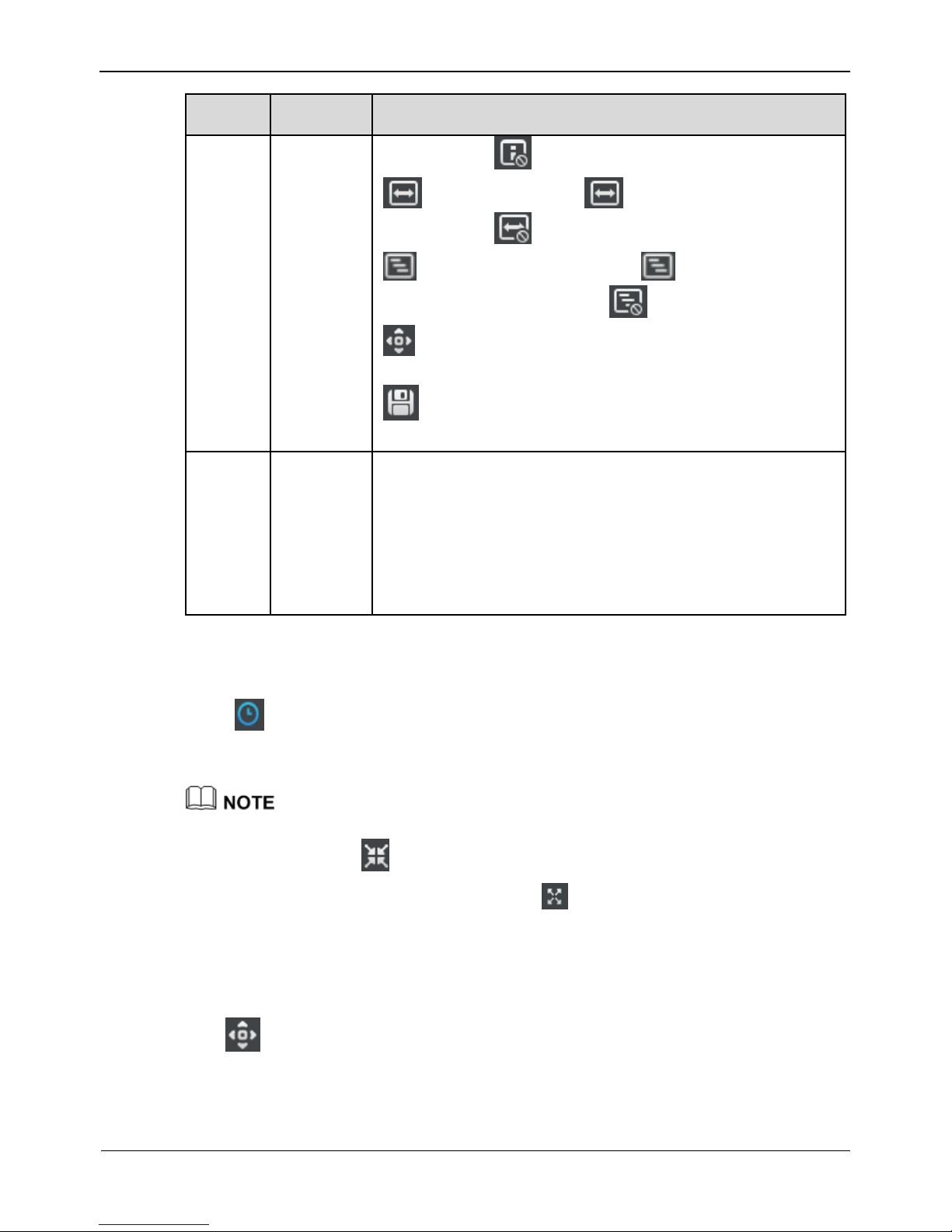
Maximum 5 OSD items in the OSD field..
Click to set the OSD displayed left-aligned. Click to set the OSD display
right-aligned.
Select an OSD item, click to move up the OSD display items, and click
to move down the OSD display items.
Click Advanced to set the time format, font color, font transparency and font on lighted
back.
Step 3 Click Apply.
The message "Apply success" is displayed.
Step 4 Click OK.
The system saves the settings.
----End
8.3.6 Privacy Masking
Step 1 Setting>NVR Setup>Channel>Privacy Masking.
The Privacy Masking interface is displayed, as shown in Figure 8-11.
Figure 8-11 Privacy Masking interface
Step 2 Click the button on to enable Privacy Masking.
Page 58

8 Setting
Network Video Recorder(NVR)
User Manual
50 Issue V1.0 (2018-05-11)
Step 3 Press and hold the left mouse button, and drag on the preview image to cover the part
to be masked.
Click the right mouse button on the preview image to clear the masked area.
You can click Reset to configure the masked area again.
Step 4 Click Apply. The message “Apply success” is displayed.
Step 5 Click OK. The system saves the settings.
----End
8.3.7 Motion Alarm
The following functions are provided:
Enable motion alarm
Set motion alarm schedule
Set motion area
Set alarm linkage
Take the following steps to set motion alarm:
Step 1 Setting>NVR Setup>Channel>Motion Alarm.
The motion alarm interface is displayed, as shown in Figure 8-12.
Figure 8-12 Motion Alarm interface
Page 59

Setting
Network Video Recorder(NVR)
User Manual
Issue V1.0 (2018-05-11) 51
Step 2 Select channel ID.
Step 3 Click motion alarm button to enable motion alarm.
Step 4 Set motion area.
1. Click , the motion area setting interface is displayed, as shown in Figure 8-13.
Figure 8-13 Motion Area interface
2. Press and hold the left mouse button and drag on the preview image to create a
motion area.
Click Clear to clear the motion area.
Step 5 Set alarm interval and sensitivity.
Step 6 Set motion alarm schedule.
Step 7 Click , the schedule setting page is displayed, as shown in Figure 8-14.
Figure 8-14 schedule setting interface
Page 60

8 Setting
Network Video Recorder(NVR)
User Manual
52 Issue V1.0 (2018-05-11)
Method 1:Click left mouse button to select any time point within 0:00-24:00 from
Monday to Sunday as shown in Figure 8-14.
Method 2:Hold down the left mouse button, drag and release mouse to select the
deployment time within 0:00-24:00 from Monday to Sunday.
NOTE
When you select time by dragging the cursor, the cursor cannot be moved out of the time
area. Otherwise, no time can be selected.
Method 3:Click in the deployment time page to select the whole day or whole
week.
Deleting deployment time: Click again or inverse selection to delete the selected
deployment time.
Step 8 Check Channel Record. Select a channel ID, input the post record to enable record
linkage.
Step 9 Check Channel PTZ. Select a channel ID and preset to enable PTZ linkage. Click
to add another Channel PTZ.
Step 10 Check Alarm Output. Select alarm output channel ID and alarm output time(s) to
enable alarm output linkage.
Step 11 Check Send Email to enable email linkage.
Step 12 Click Apply. The message "Apply success" is displayed.
Step 13 Click OK. The system saves the settings.
8.3.8 Intelligence Analyse Alarm
The following functions are provided:
Enable intelligence analyse alarm
Set intelligence analyse schedule
Set alarm linkage
Take the following steps to set intelligence analyse alarm:
Step 1 Setting>NVR Setup>Channel>Intelligence Analyse Alarm.
The intelligence analyse alarm interface is displayed, as shown in Figure 8-15.
Page 61

Setting
Network Video Recorder(NVR)
User Manual
Issue V1.0 (2018-05-11) 53
Figure 8-15 Intelligence Analyse Alarm interface
Step 2 Select channel ID.
Step 3 Click intelligence analyse alarm button to enable intelligence analyse alarm.
Step 4 Set schedule.
For details, see 8.3.7 Step 6 Set motion alarm schedule.
Step 5 Check Channel Record. Select a channel ID, input the post record to enable record
linkage.
Step 6 Check Channel PTZ. Select a channel ID and preset to enable PTZ linkage. Click
to add another Channel PTZ.
Step 7 Check Alarm Output. Select alarm output channel ID and alarm output time(s) to
enable alarm output linkage.
Step 8 Check Send Email to enable email linkage.
Step 9 Click Apply. The message "Apply success" is displayed.
Step 10 Click OK. The system saves the settings.
8.3.9 Video Lost Alarm
The following functions are provided:
Enable video lost alarm
Set video lost schedule
Set alarm linkage
Page 62

8 Setting
Network Video Recorder(NVR)
User Manual
54 Issue V1.0 (2018-05-11)
Take the following steps to set video lost alarm:
Step 1 Setting>NVR Setup>Channel>video lost Alarm ,
The video lost alarm interface is displayed, as shown in Figure 8-16.
Figure 8-16 Video Lost Alarm interface
Step 2 Select channel ID.
Step 3 Click video lost alarm button to enable video lost alarm.
Step 4 Set schedule.
For details, see 8.3.7 Step 6 Set motion alarm schedule.
Step 5 Check Channel Record. Select a channel ID, input the post record to enable record
linkage.
Step 6 Check Channel PTZ. Select a channel ID and preset to enable PTZ linkage. Click
to add another Channel PTZ.
Step 7 Check Alarm Output. Select alarm output channel ID and alarm output time(s) to
enable alarm output linkage.
Step 8 Check Send Email to enable email linkage.
Step 9 Click Apply. The message "Apply success" is displayed.
Step 10 Click OK. The system saves the settings.
Page 63

Setting
Network Video Recorder(NVR)
User Manual
Issue V1.0 (2018-05-11) 55
8.3.10 Alarm Input
Take the following steps to set alarm input:
Step 1 Setting>NVR Setup>Channel>Alarm Input.
The alarm input interface is displayed, as shown in Figure 8-17.
Figure 8-17 Alarm Input interface
Step 2 Select channel ID.
Step 3 Select alarm I/O channel.
Step 4 Input the I/O alarm name.
Step 5 Click I/O Alarm button to enable I/O alarm.
Step 6 Select the valid voltage level from the drop-down list box.
Step 7 When the alarm level is set to high, it will generate alarm signal when the COM
terminal and the IN terminal is connected; when the alarm level is set to low, it will
generate alarm signal when the COM terminal and the IN terminal is disconnected.
Step 8 Set schedule.
For details, see 8.3.7 Step 6 Set motion alarm schedule.
Step 9 Check Channel Record. Select a channel ID, input the post record to enable record
linkage.
Step 10 Check Channel PTZ. Select a channel ID and preset to enable PTZ linkage. Click
to add another Channel PTZ.
Page 64

8 Setting
Network Video Recorder(NVR)
User Manual
56 Issue V1.0 (2018-05-11)
Step 11 Check Alarm Output. Select alarm output channel ID and alarm output time(s) to
enable alarm output linkage.
Step 12 Check Send Email to enable email linkage.
Step 13 Click Apply. The message "Apply success" is displayed.
Step 14 Click OK. The system saves the settings.
8.3.11 Camera Maintenance
On the Camera Maintenance interface, you can restore factory setup and restart the
camera of selected channel.
Take the following steps to set alarm input:
Step 1 Setting>NVR Setup>Channel>Camera Maintenance.
The camera maintenance interface is displayed, as shown in Figure 8-18.
Figure 8-18 Alarm Input interface
Step 2 Select channel ID.
Step 3 Click the Reserve IP Address button.
If the button is enable, reserve the IP address of camera when the camera restore
factory setup.
If the button is disable, the IP address of camera will be reset to factory setup when the
camera restores factory setup.
Step 4 Click to restore factory setup, and click to restart the camera.
8.4 Live Video Layout
On the Live Video Layout interface, you can set a live video layout so that it can be
used on the Live Video interface.
The following functions are provided:
Creating a layout
Deleting an existing layout
Editing an existing layout
Page 65

Setting
Network Video Recorder(NVR)
User Manual
Issue V1.0 (2018-05-11) 57
Creating a layout
Take the following steps to create a layout:
Step 1 Choose Setting>NVR Setup> Live Video Layout.
The Live Video Layout interface appears, as shown in Figure 8-19.
Figure 8-19 Live Video Layout interface
Step 2 Click New. The layout creation interface appears, as shown in Figure 8-20.
Step 3 Enter a name in the Layout Name field.
Page 66

8 Setting
Network Video Recorder(NVR)
User Manual
58 Issue V1.0 (2018-05-11)
Figure 8-20 Layout creation interface
Step 4 Set the save location of the new layout by choosing Shared Layout or My Layout from
the Belong To dropdown list.
If the new layout is saved to Shared Layout, it can be used by all users after logging in to
the NVR.
If the new layout is saved to My Layout, it can be used only by the current user.
Only users with the privilege to create shared layouts can save their layouts to Shared
Layout.
Step 5 Set camera sequencing. If you enable camera sequencing, set the camera sequencing
interval to 5s, 10s, 30s, or 60s.
Step 6 Select a screen splitting format.
Click a button in . The buttons
indicate1 screen, 4 screens, 8 screens, 9 screens, 16 screens and 32 screens from left to
right.
Step 7 Click and drag a device in the Cameras pane to the screen.
Step 8 Click OK., the system save the settings automatically.
-----End
Page 67

Setting
Network Video Recorder(NVR)
User Manual
Issue V1.0 (2018-05-11) 59
8.5 Record
8.5.1 Record Policy
On the Record Policy interface, you can set scheduled record, record audio, storage
policy.
Step 1 Choose Setting>NVR Setup>Record>Record Policy.
The Record Policy interface appears, as shown in Figure 8-21.
Figure 8-21 Record Policy interface
Step 2 Check the box preceding the device on which scheduled recording and alarm recording
need to be enabled and select the corresponding code stream for recording.
Step 3 Click .
The Record Policy setting interface appears, as shown in Figure 8-22, which provides
detailed configuration of video recording.
Page 68

8 Setting
Network Video Recorder(NVR)
User Manual
60 Issue V1.0 (2018-05-11)
Figure 8-22 Record Policy setting interface
Step 4 Set a record plan.
The record plans of 24*7-hourand scheduled recording are available.
If you select timed recording, set the corresponding time as follows:
Click following the schedule setting. The Schedule Setting interface appears,
as shown in Figure 8-23.
Figure 8-23 Schedule Setting interface
Set the time segment of scheduled record.
Page 69

Setting
Network Video Recorder(NVR)
User Manual
Issue V1.0 (2018-05-11) 61
Click Ok.
Step 5 Enable or disable record audio. To enable record audio, click ON.
Step 6 Set a storage policy.
The following storage policies are available:
Overwrite in the case of full hard disks
Save days
Step 7 Set a hard disk group for storing video records.
Step 8 Set a code stream of recording.
Step 9 Click OK to save the setting and exit the Record Policy interface.
Step 10 Click Apply on the Record Policy interface. The "Apply success" prompt is
displayed.
Step 11 Click OK. The setting is saved automatically.
If another prompt is displayed, re-set the parameters to meet requirements.
8.5.2 Storage
On the Storage interface, you can:
View the statuses of the hard disks of the NVR.
View details of the hard disks, including capacity, used space, and usable space.
Unload and format hard disks.
When using the NVR for the first time, format the hard disks loaded to the NVR; otherwise,
video files cannot be written to the hard disks.
Choose Setting > NVR Setup>Record>Storage.
The Storage Configuration interface appears, as shown in Figure 8-24.
Page 70

8 Setting
Network Video Recorder(NVR)
User Manual
62 Issue V1.0 (2018-05-11)
Figure 8-24 Storage Configuration interface
Before removing a hard disk from the NVR, unload the hard disk.
8.6 Network Service
8.6.1 DDNS
Connect the specified camera to the Internet, and obtain the user name and password
for logging into the Dynamic Domain Name System (DDNS) server.
Step 1 Choose Setting > NVR Setup>Network Service>DDNS.
The DDNS interface is displayed, as shown in Figure 8-25.
Page 71

Setting
Network Video Recorder(NVR)
User Manual
Issue V1.0 (2018-05-11) 63
Figure 8-25 DDNS interface
Step 2 Set the parameters according to Table 8-7.
Table 8-7 DDNS parameters
Parameter
Description
Setting
DDNS
Indicates whether to enable the
DDNS service.
[Setting method]
Click the button on to
enable DDNS.
[Default value]
OFF
Provider
DDNS service provider.
Currently, WBoxDDNS, 3322
DynDns and no_IP are supported.
[Setting method]
Select a value from the
drop-down list box.
[Default value]
WboxDDNS
NOTE
Set this parameter based on
the site requirements.
Page 72

8 Setting
Network Video Recorder(NVR)
User Manual
64 Issue V1.0 (2018-05-11)
Parameter
Description
Setting
Network card
Ethernet interface of NVR.
[How to set]
Select from drop-down list
box.
[Default value]
LAN WAN
Host Name
Host name customized by a user.
[Setting method]
Enter a value manually.
[Default value]
-.wboxddns.com
Step 3 Click Test DDNS.
Step 4 Click Apply.
If the message "Apply success" is displayed, click OK. The system saves the
settings.
If other information is displayed, set the parameters correctly.
8.6.2 PPPoE
Obtain the PPPoE user name and password from the network carrier.
Step 1 Choose Setting > NVR Setup>Network Service>PPPoE.
The PPPoE interface is displayed, as shown in Figure 8-26.
Page 73

Setting
Network Video Recorder(NVR)
User Manual
Issue V1.0 (2018-05-11) 65
Figure 8-26 The PPPoE interface
Step 2 Click the button on to enable PPPoE. Set the parameters according to Table 8-8.
Table 8-8 PPPoE parameters
Parameter
Description
Setting
PPPoE
Indicates whether to enable the
PPPoE service.
[Setting method]
Click the button on.
[Default value]
OFF
Account
PPPoE user name provided by the
network carrier.
[Setting method]
Enter a value manually.
Password
Password provided by the
network carrier.
[Setting method]
Enter a value manually.
Step 3 Click Apply.
If the message "Apply success" is displayed, click OK. The system saves the
settings.
If other information is displayed, set the parameters correctly.
-----End
Page 74

8 Setting
Network Video Recorder(NVR)
User Manual
66 Issue V1.0 (2018-05-11)
8.6.3 SMTP
If the Simple Mail Transfer Protocol (SMTP) function is enabled, the device
automatically sends JPG images and alarm information to specified email addresses
when an alarm is generated.
Step 1 Choose Setting > NVR Setup>Network Service>SMTP.
The SMTP interface is displayed, as shown in Figure 8-27.
Figure 8-27 The SMTP interface
Step 2 Set the parameters according to Table 8-9.
Table 8-9 SMTP parameters
Parameter
Description
Setting
SMTP
N/A
[Setting method]
Select the check box.
SMTP Server
Address
IP address of the SMTP server.
[Setting method]
Enter a value manually.
SMTP Server
Port
Port number of the SMTP server.
[Setting method]
Enter a value manually.
[Default value]
25
User Name
User name of the mailbox for
sending emails.
[Setting method]
Enter a value manually.
Page 75

Setting
Network Video Recorder(NVR)
User Manual
Issue V1.0 (2018-05-11) 67
Parameter
Description
Setting
Password
Password of the mailbox for
sending emails.
[Setting method]
Enter a value manually.
Sender E-mail
Address
Mailbox for sending emails.
[Setting method]
Enter a value manually.
Recipient_Email_Address1
(Mandatory) Email address of
recipient 1.
[Setting method]
Enter a value manually.
Recipient_Email_Address2
(Optional) Email address of
recipient 2.
Recipient_Email_Address3
(Optional) Email address of
recipient 3.
Recipient_Email_Address4
(Optional) Email address of
recipient 4.
Recipient_Email_Address5
(Optional) Email address of
recipient 5.
Transport Mode
Email encryption mode. Set this
parameter based on the
encryption modes supported by
the SMTP server.
[Setting method]
Select a value from the
drop-down list box.
[Default value]
No Encrypted
Step 3 Click Apply.
If the message "Apply success" is displayed, click OK. The system saves the
settings.
If other information is displayed, set the parameters correctly.
-----End
8.6.4 IP Filter
Set the IP address in specified network segment to allow access or prohibit access. .
Step 1 Choose Setting > NVR Setup >Network Service>IP Filter.
Step 2 Click the button on to enable black and white name, The Black and White Name page
is displayed, as shown in Figure 8-28.
Page 76

8 Setting
Network Video Recorder(NVR)
User Manual
68 Issue V1.0 (2018-05-11)
Figure 8-28 Black and White Name interface
Step 3 Select a rule type from the drop-down list box.
Black list: Forbid the specified segment from connecting and accessing the NVR.
White list: Allow the specified network segment connecting and accessing the NVR.
Step 4 Add a rule type
1. Click , the IP address segment Configuration page is displayed, as show in
Figure 8-29.
Figure 8-29 IP Address Segment interface
2. Enter value manually for begin IP address, end IP address, description.
Page 77

Setting
Network Video Recorder(NVR)
User Manual
Issue V1.0 (2018-05-11) 69
3. Click OK. The system saves the settings. And the name listed in the black (white)
list.
4.
Select a name in the list and click to delete the name from the list.
Select a name in the list and click to edit the name in the list.
Only one rule type is available, and the last rule type set is efficient.
8.7 External Device
8.7.1 Display screen
Configure the external display device connect to NVR.
Step 1 Choose Setting >NVR Setup>External Device>Display screen,
The display screen interface is displayed, as shown in Figure 8-30.
Figure 8-30 Display screen interface
Step 2 Select a major resolution from the drop-down list box. The major resolution includes:
1080P, 720P, 1024*768, 3840*2160.
Step 3 Click the button on to enable the minor screen.
Step 4 Select a minor resolution from the drop-down list box. The minor resolution includes:
1080P, 720P, 1024*768, 3840*2160.
Step 5 Click Apply, the “Be sure to modify, the device will restart” dialog box prompt.
Page 78

8 Setting
Network Video Recorder(NVR)
User Manual
70 Issue V1.0 (2018-05-11)
Step 6 Click OK, the system saves the settings.
8.8 Alarm
8.8.1 Alarm Input
Choose Setting>NVR Setup>Alarm>Alarm Input.
For details, see 8.3.10 Alarm Input
8.8.2 .Alarm Out
Step 1 Choose Setting>NVR Setup>Alarm>Alarm Out.
The Alarm Out interface appears, as shown in Figure 8-31.
Figure 8-31 Alarm Out interface
Step 2 Set the parameters according to Table 8-10.
Page 79

Setting
Network Video Recorder(NVR)
User Manual
Issue V1.0 (2018-05-11) 71
Table 8-10 Alarm out parameters
Parameter
Description
Setting
Alarm Output
ID of the alarm output channel.
NOTE
The number of alarm output
channels depends on the device
model.
[Setting method]
Select a value from the
drop-down list box.
[Default value]
1
Name
Alarm output channel name.
[Value range]
0 to 32 bytes
Valid Signal
The options are as follows:
Close: An alarm is generated
when an external alarm signal
is received.
Open: An alarm is generated
when no external alarm signal
is received.
[Setting method]
Select a value from the
drop-down list box.
[Default value]
Close
Alarm Out
Mode
When the device receives I/O
alarm signals, the device sends
the alarm information to an
external alarm device in the mode
specified by this parameter. The
options include the switch mode
and pulse mode.
NOTE
If the switch mode is used, the
alarm frequency of the device must
be the same as that of the external
alarm device.
[Setting method]
Select a value from the
drop-down list box.
[Default value]
Switch Mode
Manual Control
Control the alarm output.
[Setting method]
Click Start or Stop.
Step 3 Click , the system saves the settings.
8.8.3 Disk Alarm
Step 1 Choose Setting>NVR Setup>Alarm>Disk Alarm.
The Disk Alarm interface appears, as shown in Figure 8-32.
Page 80

8 Setting
Network Video Recorder(NVR)
User Manual
72 Issue V1.0 (2018-05-11)
Figure 8-32 Disk Alarm interface
Step 2 Click the button ON to enable disk full alarm (disk error alarm, no disk alarm) function.
Step 3 Select the alarm output, then choose alarm output channel number and set the alarm out
time.
Step 4 Click Apply, the “Apply success” dialog box prompt.
Step 5 Click OK, the system saves the settings.
8.9 Privilege
Privilege group setting
User privileges include:
Video preview
Video control
Playback
Backup
Record policy
Disk configuration
Alarm Search
Device Management
Manage privilege
Page 81

Setting
Network Video Recorder(NVR)
User Manual
Issue V1.0 (2018-05-11) 73
Device parameter configuration
System maintenance
Step 1 Choose Setting>NVR Setup>Privilege.
The Privilege interface appears, as shown in Figure 8-33.
Figure 8-33 Privilege interface
Step 2 Add or delete a user.
Adding a user
1. Click Add.
The Add User dialog box appears, as shown in Figure 8-34.
Page 82

8 Setting
Network Video Recorder(NVR)
User Manual
74 Issue V1.0 (2018-05-11)
Figure 8-34 Add user interface
2. Enter a username, password and confirm password.
The password should include letter, character and number.
The password must be not less than 8.
3. Select a Group from the drop-down list box.
4. Enter value manually for notes.
5. Select the operation privileges in the left list of the add user interface and select the
channels in the right list.
6. Click OK.
The user is set successfully.
Page 83

Setting
Network Video Recorder(NVR)
User Manual
Issue V1.0 (2018-05-11) 75
Editing user
Select a user and click , the Edit User interface is displayed, as shown in Figure
8-35.
Figure 8-35 Edit user interface
7. Modify information of the user (user name, password, confirm password, group,
note and manage privilege).Click OK.
The user is modified successfully.
Deleting a user
Select a user and click .
Page 84

8 Setting
Network Video Recorder(NVR)
User Manual
76 Issue V1.0 (2018-05-11)
The Delete Group dialog box appears as shown in Figure 8-36.
Figure 8-36 Confirm to delete interface
8. Click Yes.
The system returns to the Groups interface and the user is deleted successfully.
The default user is Administrator and cannot be deleted or modified.
-----End
8.10 Device Log
8.10.1 Alarm Log
Choose Setting > NVR Setup>Device Log>Alarm Log.
The Alarm Log interface appears, as shown in Figure 8-37.
Page 85

Setting
Network Video Recorder(NVR)
User Manual
Issue V1.0 (2018-05-11) 77
Figure 8-37 Alarm Log interface
Query alarm information
Step 1 Select the warning type from the drop-down list.
Step 2 Enter the begin time and end time.
Step 3 Click , the search results will display below the alarm log interface as shown in
Figure 8-38.
Page 86

8 Setting
Network Video Recorder(NVR)
User Manual
78 Issue V1.0 (2018-05-11)
Figure 8-38 Alarm query interface
8.10.2 Operation Log
Choose Setting > NVR Setup>Device Log>Operation Log.
The Operation Log interface appears, as shown in Figure 8-39.
Page 87

Setting
Network Video Recorder(NVR)
User Manual
Issue V1.0 (2018-05-11) 79
Figure 8-39 Operation Log interface
Query operation log information
Step 1 Select the log type from the drop-down list.
Step 2 Enter the begin time and end time.
Step 3 Click , the search results will display below the operation log interface as shown in
Figure 8-40.
Page 88

8 Setting
Network Video Recorder(NVR)
User Manual
80 Issue V1.0 (2018-05-11)
Figure 8-40 Operation query interface
-----End
8.11 Scheduled Reboot
Step 1 Choose Setting> NVR Setup>Scheduled Reboot.
The Scheduled Reboot interface appears, as shown in Figure 8-41.
Page 89

Setting
Network Video Recorder(NVR)
User Manual
Issue V1.0 (2018-05-11) 81
Figure 8-41 Scheduled Reboot interface
Step 2 Click ON to enable scheduled reboot.
Step 3 Add or Delete reboot schedule.
Adding a reboot schedule
1. Tick Week and select the reboot time from the down-drop list box.
2. Click Add, the reboot schedule is added successfully.
Deleting a reboot schedule
3. Tick the reboot schedule ID.
4. Click Delete, the reboot schedule is deleted successfully.
Step 4 Click Apply, the system saves the settings.
-----End
8.12 System
Step 1 Choose Setting> NVR Setup>System.
The System interface appears, as shown in Figure 8-42.
Page 90

8 Setting
Network Video Recorder(NVR)
User Manual
82 Issue V1.0 (2018-05-11)
Figure 8-42 System interface
Step 2 Click the button ON to enable Live Video window Tip, Login automatically, Auto
Lock and window show maximize while alarm triggering.
Step 3 Select wait time from the drop-down list box.
Step 4 Select lock screen mode from the drop-down list box.
Step 5 Click Apply, the system saves the settings.
8.13 Maintenance
Step 1 Choose Setting> NVR Setup>Maintenance.
The Maintenance interface appears, as shown in Figure 8-43.
Figure 8-43 Maintenance interface
Step 2 Click the Reserve IP Address button.
If the button is enable, reserve the IP address of camera when the camera restore
factory setup.
Page 91

Setting
Network Video Recorder(NVR)
User Manual
Issue V1.0 (2018-05-11) 83
If the button is disable, the IP address of camera will be reset to factory setup when the
camera restores factory setup.
Step 3 Click .
The Are you sure to restore? dialog box appears.
Step 4 Click Yes, the device restore to the factory settings.
-----End
Page 92

9 Web Access
Network Video Recorder(NVR)
User Manual
84 Issue V1.0 (2018-05-11)
9 Web Access
The NVR is embedded with a web server and supports mainstream browsers such as
Internet Explorer, Chrome, Firefox, and Safari. Operations such as quick setup, realtime preview, video playback, alarm search, NVR setup, and camera setup can be
performed through the web.
9.1 Login
The default IP address of the NVR is 192.0.0.64 when network interface 1 is used and
is 192.0.0.64 when network interface 2 is used. To access the NVR, enter the
corresponding IP address in the address bar of your web browser. If the NVR is
connected through network interface 1, enter http://192.0.0.64.
Before accessing the NVR through the web, ensure that the network connection is
correct and smooth.
Identify the connected network interface and enter the corresponding IP address in
the address bar of your browser.
Figure 9-1 shows the web-based login interface of the NVR.
Figure 9-1 Login interface of the NVR
Enter your user name and password to access the main interface.
The default user name and password are both admin.
Page 93

Web Access
Network Video Recorder(NVR)
User Manual
Issue V1.0 (2018-05-11) 85
9.2 Live Video
On the Live Video interface, you can select an online camera in the left Cameras pane
and view the corresponding live video.
Click Live Video. The Live Video interface appears, as shown in Figure 9-2.
Figure 9-2 Live Video interface
9.3 Video Playback
On the Playback interface, you can search for and play videos.
Operation procedure
Step 1 Click Playback in the navigation bar at the top of the web interface.
The Playback interface appears, as shown in Figure 9-3.
Step 2 Select a camera.
Click a camera in the Cameras pane. A selected camera is marked with . An
unselected camera is marked with .
Step 3 Select a date.
Select a date in the Date pane. Click and to change months or click
and to change years. indicates the selected date. The green color indicates
that there are videos captured on that day.
Page 94

9 Web Access
Network Video Recorder(NVR)
User Manual
86 Issue V1.0 (2018-05-11)
Step 4 Display videos.
After a camera and date are selected, video information is displayed below the video
pane. The time scale above the file axis shows the different time points of video
recording. The time in blue in the middle is the time of the video being played.
The file axis displays videos. Alarm videos are in red and ordinary videos are in green.
Step 5 Play a video.
After selecting a camera and date, the video begin to play.
: indicates play, stop, fast-forward, and fast-backward from left to right.
Figure 9-3 Playback interface
-----End
9.4 Alarm Search
Step 1 Click Alarm Search in the navigation bar at the top of the web interface.
The Alarm Search interface appears, as shown in Figure 9-4.
Page 95

Web Access
Network Video Recorder(NVR)
User Manual
Issue V1.0 (2018-05-11) 87
Figure 9-4 Alarm Search interface
Step 2 Select a camera in the left Cameras pane.
Step 3 Select an alarm type from the Type dropdown list.
Step 4 Select a date.
Select a date in the Date pane. Click and to change months or click
and to change years. indicates the selected date. The red color indicates
that there are alarm records generated on that day.
Step 5 Display videos.
After a camera and date are selected, alarm video files are displayed in the Type pane.
Step 6 Play a video.
Click an alarm video file and the video begin to play.
Step 7 Back up an alarm record.
Select a video and click the Backup button to back up the video to the backup folder.
-----End
9.5 NVR Setup
Click NVR Setup in the navigation bar at the top of the web interface.
The NVR Setup interface appears, as shown in Figure 9-5.
You can set NVR parameters. For details, see section 8.1 "NVR Setup".
Page 96

9 Web Access
Network Video Recorder(NVR)
User Manual
88 Issue V1.0 (2018-05-11)
Figure 9-5 NVR Setup interface
-----End
Page 97

FAQ
Network Video Recorder(NVR)
User Manual
Issue V1.0 (2018-05-11) 89
10 FAQ
1. Why is the NVR self-test screen frozen?
Use the methods below to fix the problem:
Method 1: Check whether the NVR is equipped with a hard disk.
Method 2: Check whether the NVR is equipped with an unformatted hard disk.
Method 3: Check whether the hard disk is damaged.
If a hard disk is not required, Click continue in the lower right corner of the screen to
resume the startup process.
2. Why does the screen display incomplete information or is skewed?
Use the following methods below to fix the problem:
Method 1: Use the automatic adjustment function of the monitor.
Method 2: Click Adjust on the login screen. The Monitor Setup screen is displayed.
For operation details, see chapter 4 "Operation Instruction" of the Network Video
Recorder (NVR) User Guide.
3. Why no image is displayed on the monitor?
Use the following methods below to fix the problem:
Method 1: Check the power supply of the monitor.
Method 2: Check whether the monitor is connected to the NVR correctly.
Method 3: Restart the NVR.
Method 4: Check whether the monitor supports the default resolution (1024×768) of
the NVR.
 Loading...