

W box technologies 0E-13BF36, 0E-40D28WDR, 0E-13D28, 0E-21D28WDR, 0E-40BF36WDR User Manual
...Page 1
High-Resolution IR Camera
User Manual
If you have any questions, please call
W Box Tech Support 1-833-574-9124
for assistance.
E-mail:tech@wboxsupport.com
0E-13D28
0E-13BF36
0E-21D28WDR
0E-21BF36WDR
0E-40D28WDR
0E-40BF36WDR
Page 2

Page 3
High-Resolution IR Camera
User Manual
Hardware Connection
Issue V1.0 (2018-05-11) i
Precautions
Symbol
Description
It alerts you to fatal dangers which, if not avoided, may
cause deaths or severe injuries.
It alerts you to moderate dangers which, if not avoided,
may cause minor or moderate injuries.
It alerts you to risks. Neglect of these risks may cause
device damage, data loss, device performance
deterioration, or unpredictable results.
It provides a tip that may help you resolve problems or
save time.
It provides additional information.
Fully understand this document before using this device, and strictly observe rules in
this document when using this device. If you install this device in public places,
provide the tip "You have entered the area of electronic surveillance" in an eyecatching place. Failure to correctly use electrical products may cause fire and severe
injuries. To prevent accidents, carefully read the following context:
Symbols
This document may contain the following symbols whose meanings are described
accordingly.
Precautions
To prevent electric shocks or other dangers, keep power plugs dry and clean.
Strictly observe installation requirements when installing the device. The
manufacturer shall not be held responsible for device damage caused by users' nonconformance to these requirements.
Page 4

Hardware Connection
High-Resolution IR Camera
User Manual
ii Issue V1.0 (2018-05-11)
Strictly conform to local electrical safety standards and use power adapters that are
marked with the LPS standard when installing and using this device. Otherwise,
this device may be damaged.
Use accessories delivered with this device. The voltage must meet input voltage
requirements for this device.
If this device is installed in places with unsteady voltage, ground this device to
discharge high energy such as electrical surges in order to prevent the power supply
from burning out.
When this device is in use, ensure that no water or any liquid flows into the device.
If water or liquid unexpectedly flows into the device, immediately power off the
device and disconnect all cables (such as power cables and network cables) from
this device.
Do not focus strong light (such as lighted bulbs or sunlight) on this device.
Otherwise, the service life of the image sensor may be shortened.
If this device is installed in places where thunder and lightning frequently occur,
ground the device nearby to discharge high energy such as thunder strikes in order
to prevent device damage.
Avoid heavy loads, intensive shakes, and soaking to prevent damages during
transportation and storage. The warranty does not cover any device damage that is
caused during secondary packaging and transportation after the original packaging
is taken apart.
Protect this device from fall-down and intensive strikes, keep the device away from
magnetic field interference, and do not install the device in places with shaking
surfaces or under shocks.
Clean the device with a soft dry cloth. For stubborn dirt, dip the cloth into slight
neutral cleanser, gently wipe the dirt with the cloth, and then dry the device.
Do not jam the ventilation opening. Follow the installation instructions provided in
this document when installing the device.
Keep the device away from heat sources such as radiators, electric heaters, or other
heat equipment.
Keep the device away from moist, dusty, extremely hot or cold places, or places
with strong electric radiation.
If the device is installed outdoors, take insect- and moisture-proof measures to
avoid circuit board corrosion that can affect monitoring.
Remove the power plug if the device is idle for a long time.
Before unpacking, check whether the fragile sticker is damaged. If the fragile
sticker is damaged, contact customer services or sales personnel. The manufacturer
shall not be held responsible for any artificial damage of the fragile sticker.
Page 5

High-Resolution IR Camera
User Manual
Hardware Connection
Issue V1.0 (2018-05-11) iii
Special Announcement
All complete products sold by the manufacturer are delivered along with nameplates,
operation instructions, and accessories after strict inspection. The manufacturer shall
not be held responsible for counterfeit products.
This manual may contain misprints, technology information that is not accurate enough,
or product function and operation description that is slightly inconsistent with the
actual product. The manufacturer will update this manual according to product function
enhancement or changes and regularly update the software and hardware described in
this manual. Update information will be added to new versions of this manual without
prior notice.
This manual is only for reference and does not ensure that the information is totally
consistent with the actual product. For consistency, see the actual product.
Page 6

Hardware Connection
High-Resolution IR Camera
User Manual
iv Issue V1.0 (2018-05-11)
Contents
1 Hardware Connection ............................................................................................. 6
2 Eyeball Camera......................................................................................................... 7
2.1 Dimensions ..................................................................................................................... 7
2.2 Device Installation .......................................................................................................... 7
3 Bullet camera .......................................................................................................... 11
3.1 Dimensions .................................................................................................................... 11
3.2 Device Installation ........................................................................................................ 12
4 Web Operation ....................................................................................................... 15
4.1 Quick start .................................................................................................................... 15
4.1.1 Login and Logout ............................................................................................. 15
4.1.2 Changing the Password .................................................................................... 16
4.1.3 Main Page Layout ............................................................................................ 17
4.2 Browsing Real-Time Videos ......................................................................................... 19
4.3 Configuring the Device ................................................................................................ 21
4.3.1 Configuring the Device Information ................................................................ 21
4.4 Setting Video and Audio Stream Parameters ................................................................ 23
4.4.2 Setting SVC Stream Parameters ....................................................................... 27
4.4.3 Region of Interest ............................................................................................. 28
4.4.4 Setting Local Network Parameters ................................................................... 30
4.4.5 Configuring Device Ports ................................................................................. 33
4.4.6 Configuring the Date and Time ........................................................................ 34
4.4.7 Setting the Channel Name, Video System, and Source Resolution .................. 37
4.4.8 Setting OSD Parameters ................................................................................... 38
4.4.9 System Service ................................................................................................. 41
4.5 Configuring the Alarm Function................................................................................... 42
4.5.1 Setting Disk Alarm Parameters ........................................................................ 42
4.5.2 Setting Network Alarm Parameters .................................................................. 42
4.5.3 Setting Motion Alarm Parameters .................................................................... 43
4.5.4 Setting push message Parameters ..................................................................... 45
4.6 Configuring the Recording Function ............................................................................ 46
4.6.1 Configuring a Recording Policy ....................................................................... 46
Page 7

High-Resolution IR Camera
User Manual
Hardware Connection
Issue V1.0 (2018-05-11) v
4.6.2 Configuring a Recording Directory .................................................................. 48
4.6.3 Configuring the SD Card or NAS Recording ................................................... 50
4.7 Configuring the Privacy Mask Function ....................................................................... 51
4.8 Configuring the Network Service ................................................................................. 53
4.8.1 Setting 802.1x Parameters ................................................................................ 53
4.8.2 Setting DDNS Parameters ................................................................................ 54
4.8.3 Setting PPPoE Parameters ................................................................................ 55
4.8.4 Setting Port Mapping Parameters ..................................................................... 56
4.8.5 Setting SMTP Parameters ................................................................................ 58
4.8.6 Setting FTP Parameters .................................................................................... 60
4.8.7 Setting IP Filter Parameters .............................................................................. 62
4.8.8 Setting CGI Alarm Service Center Parameters ................................................. 65
4.8.9 Setting SNMP Parameters ................................................................................ 68
4.9 Privilege Manager ........................................................................................................ 71
4.10 Configuring Protocol Parameters ............................................................................... 75
4.10.1 Checking Protocol Information ...................................................................... 75
4.10.2 Setting Security Authentication ...................................................................... 75
4.10.3 Setting Multicast Parameters .......................................................................... 76
4.11 Querying Operation Logs ........................................................................................... 78
4.11.2 Querying Operation Logs ............................................................................... 78
4.11.3 Querying Alarm Logs ..................................................................................... 79
4.11.4 Reporting Logs ............................................................................................... 81
4.12 Maintaining the Device .............................................................................................. 81
4.12.1 Restarting a Device ........................................................................................ 81
4.12.2 Updating the software package ...................................................................... 82
4.12.3 Restoring a Device to Factory Settings .......................................................... 83
4.13 Local Configuration ................................................................................................... 83
5 Technical Specifications ....................................................................................... 85
Page 8
Hardware Connection
High-Resolution IR Camera
User Manual
6
Issue V1.0 (2018-05-11)
1 Hardware Connection
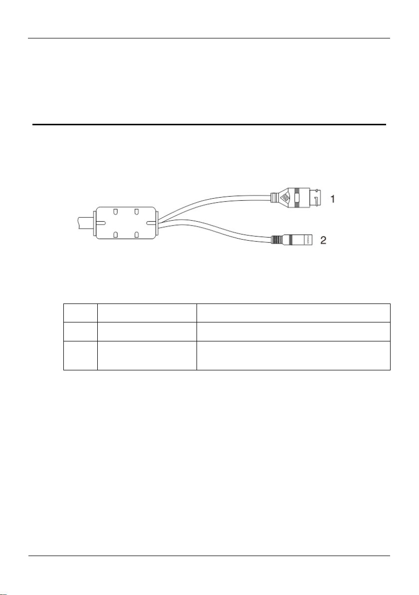
ID
Core
Description
1
Network access port
Connects to a standard Ethernet cable.
2
Power supply (DC 12V)
Connects to a 12V(-15%-+10% ) direct current
(DC) power supply.
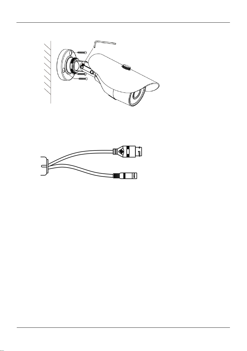
Figure 1-1 shows the power and network cables.
Figure 1-1 Power and network cables
Table 1-1 shows the description of the cable.
Table 1-1 description of the cable
Page 9
High-Resolution IR Camera
User Manual
Eyeball Camera
Issue V1.0 (2018-05-11) 7
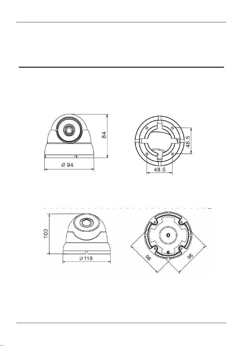
2.1 Dimensions
Figure 2-1 shows the camera dimensions of 0E-13D28 and 0E-21D28WDR.
Figure 2-1 Dimensions of 0E-13D28 and 0E-21D28WDR (unit: mm)
Figure 2-2 shows the camera dimensions of 0E-40D28WDR.
2 Eyeball Camera
Figure 2-2 Dimensions of 0E-40D28WDR (unit: mm)
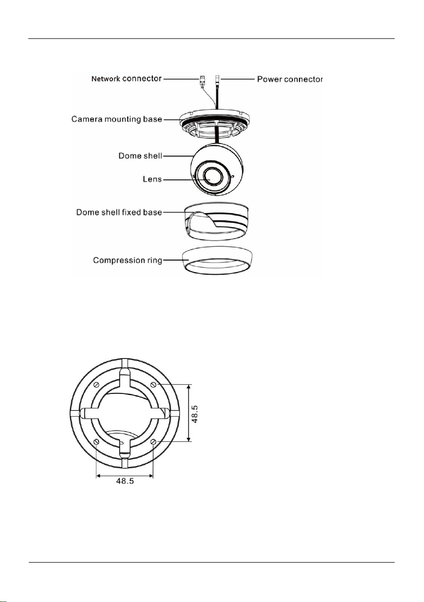
2.2 Device Installation
Step 1 Open a package, take out the camera, unscrew the camera compression ring, and
disassemble the camera, the camera components is shown in Figure 2-3.
Page 10
Eyeball Camera
High-Resolution IR Camera
User Manual
8
Issue V1.0 (2018-05-11)
Figure 2-3 Camera components
Step 2 Use the base as drill template, drill holes on the ceiling or wall, and reserve the cable
entries of the video/power cables.
Figure 2-4 and Figure 2-5 shows the dimensions of the camera mounting base.
Figure 2-4 Dimensions of the 0E-HDD1MP28 and 0E-HDD2MP28 mounting base
Page 11
High-Resolution IR Camera
User Manual
Eyeball Camera
Issue V1.0 (2018-05-11) 9
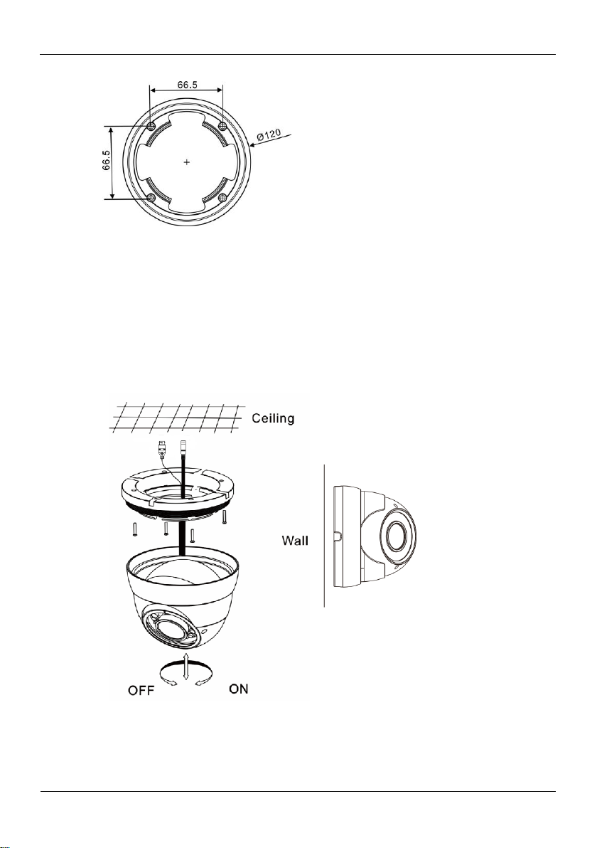
Figure 2-5 Dimensions of the 0E-HDDMO2812 mounting base
Step 3 Nail swell plastic buttons in to drilled holes, and fix the camera mounting base to the
ceiling (or wall) by use of self-tapping screws.
Step 4 Install the compression ring, the dome shell, and the dome shell fixed base on the
camera mounting base.
Figure 2-6 shows camera installation.
Figure 2-6 Camera installation
Step 5 Turn the main body, adjust the lens direction, and note the position of the dome cover
window.
Page 12
Eyeball Camera
High-Resolution IR Camera
User Manual
10
Issue V1.0 (2018-05-11)
Connect the BNC connector of the power or video cable to a video signal cable and
connect the other connector to a low-voltage power cable. After installing the camera,
directly connect the video cable and power cable.
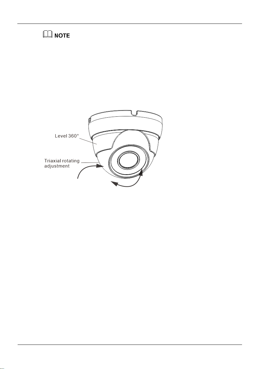
Adjust the position of the camera by triaxial rotation: rotating horizontally, rotating up
and down, and performing lens axial rotation, and adjust the camera direction and lens
alignment target.
Figure 2-7 shows monitoring direction adjustment.
Figure 2-7 Monitoring direction adjustment
Step 6 Use soft cloth to wipe the lens front glass which is likely to be soiled due to installation
for cleaning the camera, and complete product installation and debugging.
----End
Page 13
High-Resolution IR Camera
User Manual
Bullet camera
Issue V1.0 (2018-05-11) 11
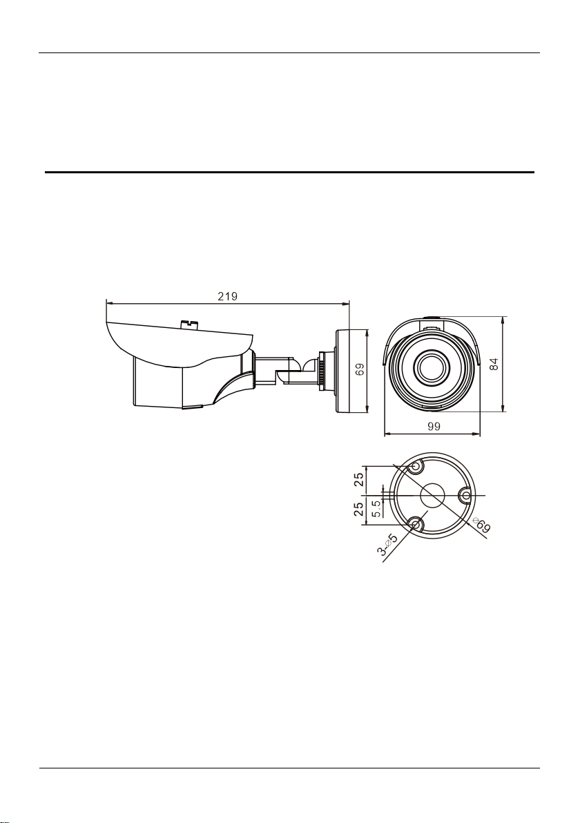
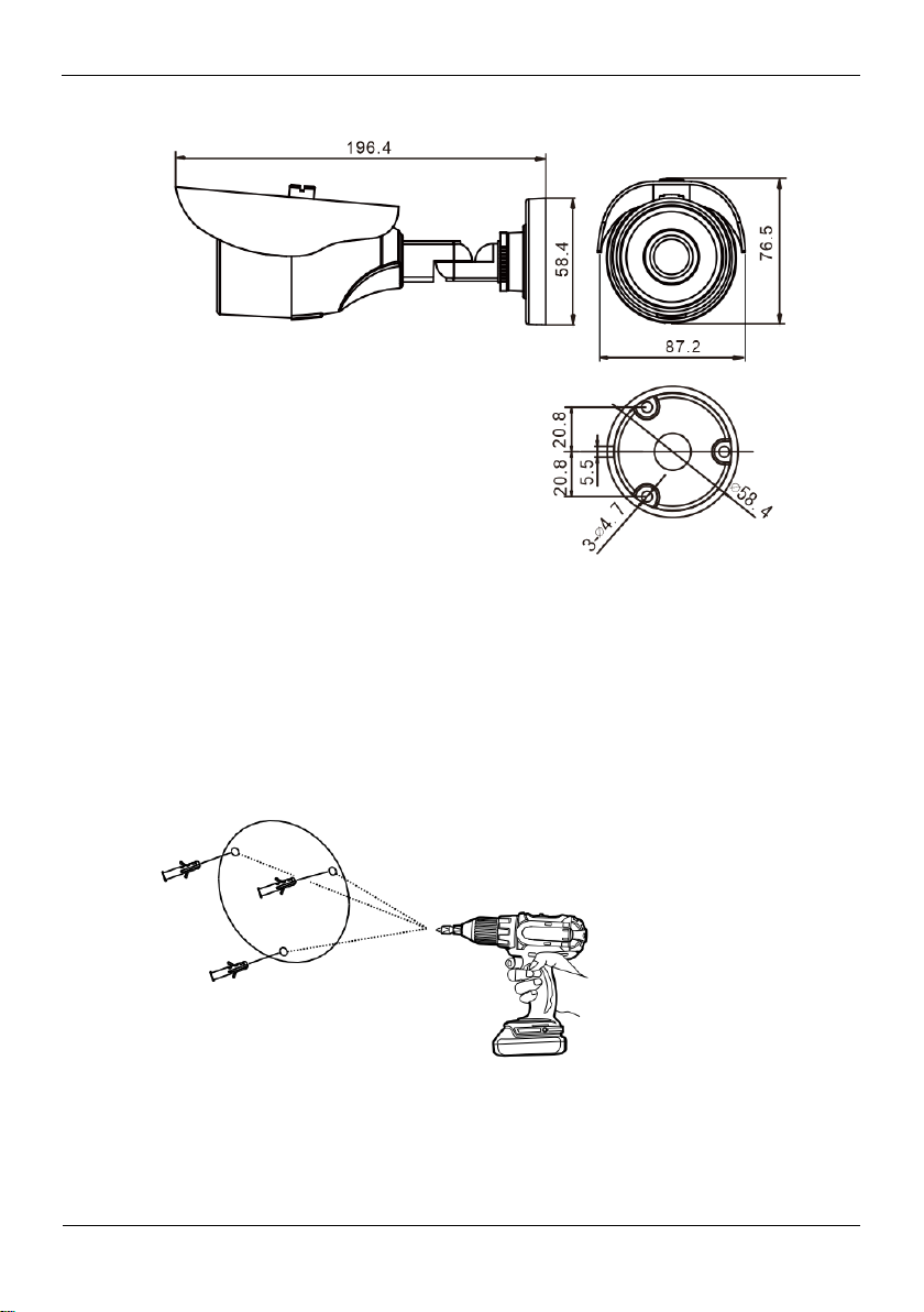
3.1 Dimensions
Figure 3-1 shows the dimensions of 0E-40BF36WDR.
Figure 3-1 dimensions of 0E-40BF36WDR
3 Bullet camera
Figure 3-2 shows the dimensions of 0E-13BF36 and 0E-21BF36WDR.
Page 14
Bullet camera
High-Resolution IR Camera
User Manual
12
Issue V1.0 (2018-05-11)
Figure 3-2 dimensions of 0E-13BF36 and 0E-21BF36WDR
3.2 Device Installation
Step 1 Stick the Installation location sticker on the ceiling or wall, Drill three holes based on
the marks on the sticker. Drive the swell plastic buttons into the holes, as shown in
Figure 3-3.
Figure 3-3 Drilling holes
Step 2 Loosen the locking screw with L-Hex Wrench and rotate the camera, then attach the
camera to the surface, as shown in Figure 3-4.
Page 15
High-Resolution IR Camera
User Manual
Bullet camera
Issue V1.0 (2018-05-11) 13
Figure 3-4 Installing camera
Step 3 Connect the Power and video cable, as shown in Figure 3-5.
Figure 3-5 Connecting cable
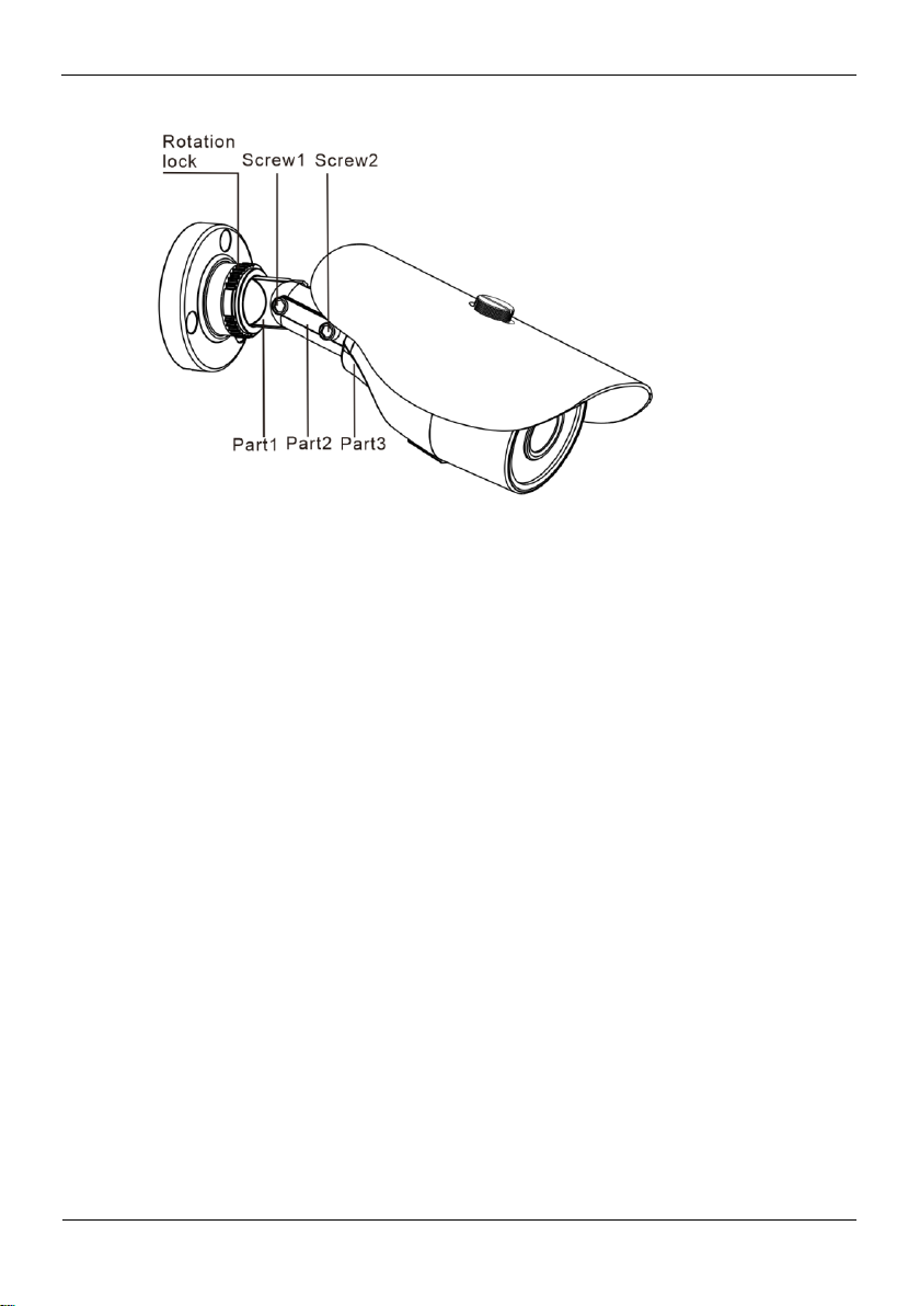
Step 4 Loosen the locking screw with L-Hex Wrench, rotate the camera to adjust the position
and image so that the camera faces the monitored area, then tighten the locking screw,
as shown in Figure 3-6.
To rotate the part 1 of the camera for 360°, loosen rotation lock.
To rotate the part 2 of the camera for180°, loosen screw 1.
To rotate the part 3 of the camera for 360°, loosen screw 2.
Page 16
Bullet camera
High-Resolution IR Camera
User Manual
14
Issue V1.0 (2018-05-11)
Figure 3-6 Adjusting monitored area
----End
Page 17
High-Resolution IR Camera
User Manual
Web Operation
Issue V1.0 (2018-05-11) 15
4 Web Operation
4.1 Quick start
4.1.1 Login and Logout
You must use Internet Explorer 7, and more to access the web management system;
otherwise, some functions may be unavailable.
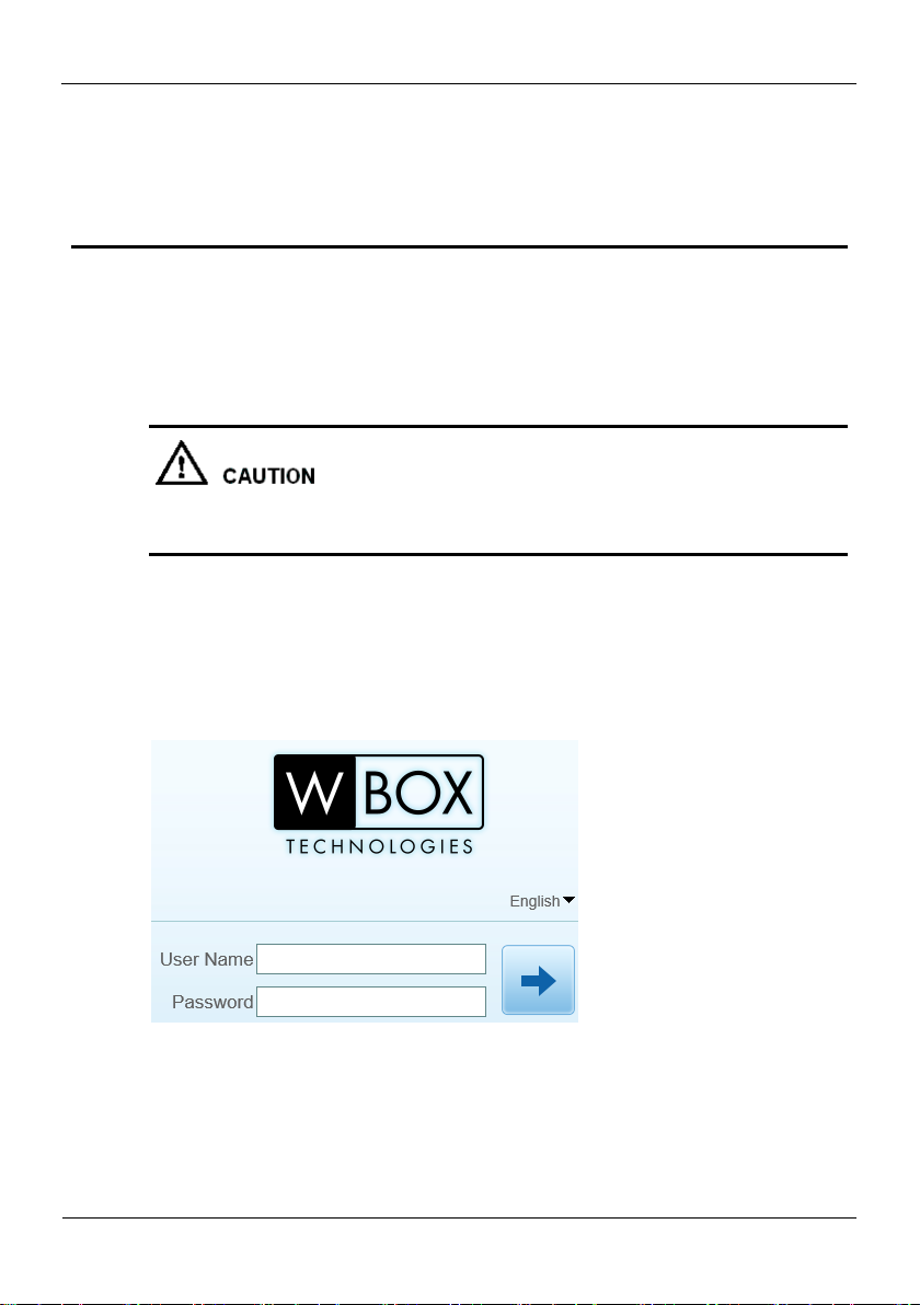
Login
Step 1 Open Internet Explorer, enter the IP address of the IP camera (default value:
192.168.1.64) in the address box, and press Enter.
The login page is displayed, as shown in Figure 4-1.
Figure 4-1 Login page
Step 2 Enter the user name, and password.
Page 18
Web Operation
High-Resolution IR Camera
User Manual
16
Issue V1.0 (2018-05-11)
The default user name is admin. The default password is admin.
Change the password to ensure system security.
You can change the system display language on the login page.
Step 3 Click .
The main page is displayed.
----End
Logout
To log out of the system, click in the upper right corner of the main page. The
login page is displayed after you log out of the system.
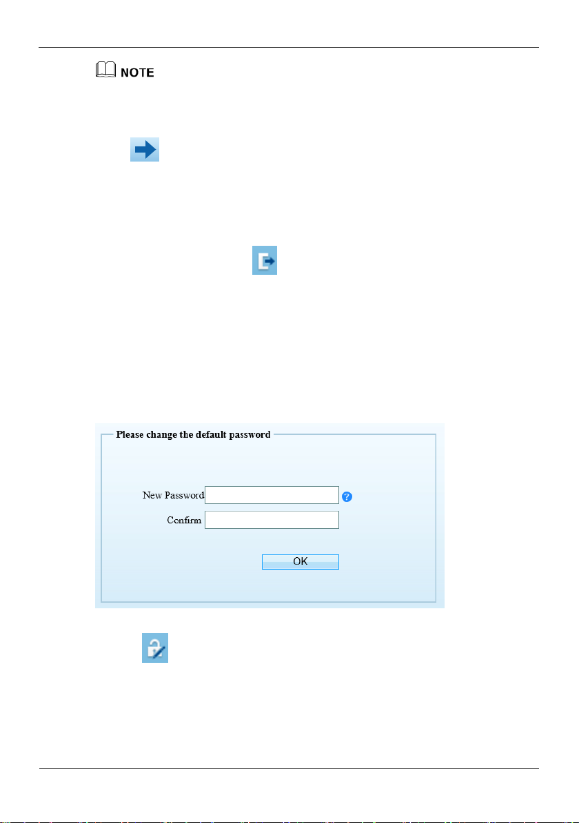
4.1.2 Changing the Password
Description
The change password page will be displayed as shown in Figure 4-2, when you login
the system for the first time.
Figure 4-2 Change the default password page
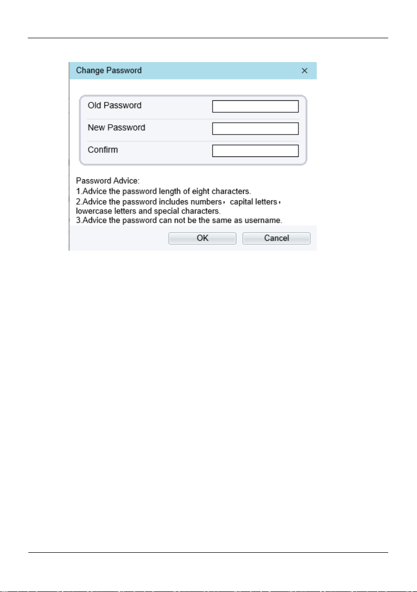
Or click to change the password for login the system, as show in Figure 4-3.
Page 19
High-Resolution IR Camera
User Manual
Web Operation
Issue V1.0 (2018-05-11) 17
Figure 4-3 Change the password page
Step 1 Enter the old password, new password, and confirmation password.
Step 2 Click OK.
If the message "Change password success" is displayed, the password is successfully
changed. If the password fails to be changed, the cause is displayed. (For example, the
new password length couldn’t be less than eight.)
Step 3 Click OK.
The login page is displayed.
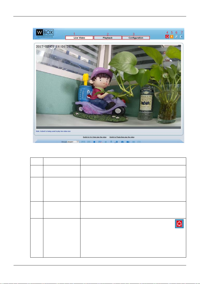
4.1.3 Main Page Layout
On the main page, you can view real-time videos, receive alarm and fault notifications,
set parameters, change the password, and log out of the system. Figure 4-4 shows the
main page layout. Table 4-1 describes the elements on the main page.
Page 20
Web Operation
High-Resolution IR Camera
User Manual
18
Issue V1.0 (2018-05-11)
Figure 4-4 Main page layout
No.
Element
Description
1
Real-time video
area
Real-time videos are played in this area. You can also set
sensor parameters.
2
Playback
You can query the playback videos in this area.
NOTE
Only when the SD card or NAS have videos that you can
query the playback videos.
3
Device
configuration
You can choose a menu to set device parameters,
including the device information, audio and video
streams, alarm setting, and privacy mask function.
4
Alarm icon
When the device generates an alarm, the alarm icon
is displayed. You can click the icon to view the alarm
information.
NOTE
When the device accepts an alarm signal, the alarm icon will
display within 10s in the web management system.
Table 4-1 Elements on the main page
Page 21
High-Resolution IR Camera
User Manual
Web Operation
Issue V1.0 (2018-05-11) 19
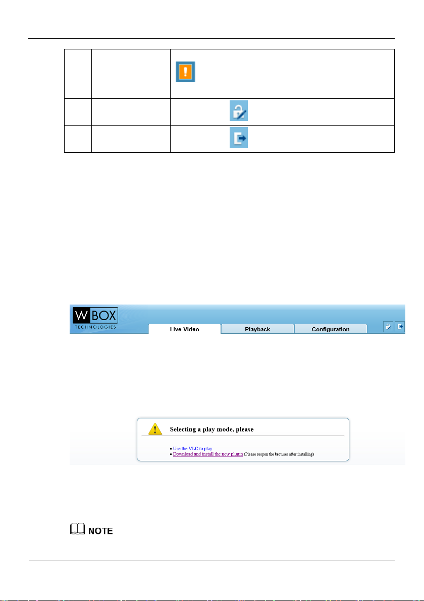
5
Fault icon
When the device encounters an exception, the fault icon
is displayed.
You can click the icon to view the fault information.
6
Change password
You can click to change the password.
7
Sign Out
You can click to return to the login page.
----End
4.2 Browsing Real-Time Videos
You can browse real-time videos in the web management system.
Preparation
You will be prompted with a message ”download and install the new plugin” as shown
in Figure 4-5 when you log in to the web management system for the first time:
Figure 4-5 Download the plug-ins page
Step 1 Click “ download and install the new plugin”, download and setup the plug-ins and
the install the plugin following the prompt.
Step 2 Reopen the browser after installing.
If the repair tips displayed when installing the control , please ignore the prompt, and
continue the installation.
Page 22
Web Operation
High-Resolution IR Camera
User Manual
20
Issue V1.0 (2018-05-11)
----End
Description
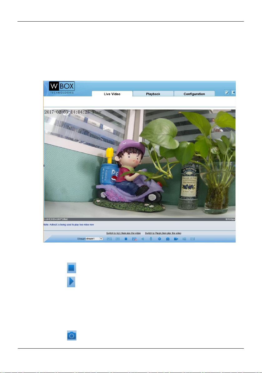
To browse real-time videos, click Live Video. The Live Video page is displayed, as
shown in Figure 4-6.
Figure 4-6 Live Video page
On the Live Video page, you can perform the following operations:
Click to stop playing a video.
Click to play a video.
Double-click in the video area to enter the full-screen mode, and double-click again
to exit.
Switch among preset streams 1, 2, and 3. For details about how to configure
streams, see
Setting Video and Audio Stream Parameters.
Click to snapshot and save the photos.
Page 23

High-Resolution IR Camera
User Manual
Web Operation
Issue V1.0 (2018-05-11) 21
Configure the sensor.
You can right-click in the video area. A shortcut menu is displayed and allows you
to enter the full-screen mode, set sensor parameters, zoom in or out, and return to
the default view.
To set sensor parameters, click to open the Sensor Setting page. On the
Sensor Setting page, you can adjust the time segment, image, scene, exposure,
white balance, focus setting, Iris setting, white balance, and noise filter as prompted.
4.3 Configuring the Device
4.3.1 Configuring the Device Information
Description
The device information includes:
Device ID, name, type, model, and MAC address.
Hardware and software versions.
Number of video channels, number of alarm input channels, number of alarm
output channels, and number of serial ports.
You can modify the device name. All other parameters can only be viewed.
When the device is upgraded, the device information is updated automatically.
Procedure
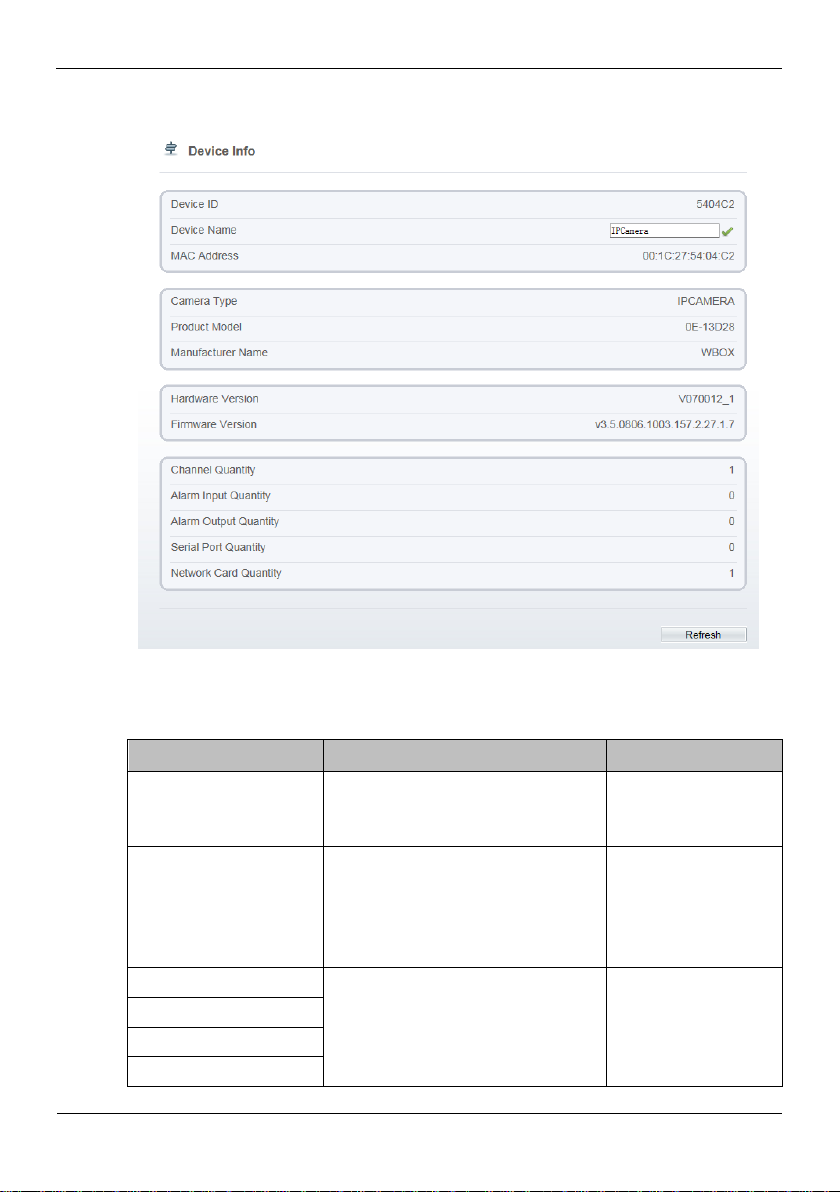
Step 1 Click Configuration > Device Info.
The Device Info page is displayed, as shown in Figure 4-7.
Page 24
Web Operation
High-Resolution IR Camera
User Manual
22
Issue V1.0 (2018-05-11)
Figure 4-7 Device Info page
Parameter
Description
Setting
Device ID
Unique device identifier used by the
platform to distinguish the devices.
[Setting method]
These parameters
cannot be modified.
Device Name
Name of the device.
NOTE
The device name cannot exceed 32
bytes or 10 simplified characters;
otherwise, the modification fails.
[Setting method]
Enter a value
manually.
MAC Address
N/A
[Setting method]
These parameters
cannot be modified.
Camera Type
Product Model
Manufacturer Name
Step 2 View the device information, set the device ID and name according to Table 4-2.
Table 4-2 Device parameters
Page 25

High-Resolution IR Camera
User Manual
Web Operation
Issue V1.0 (2018-05-11) 23
Parameter
Description
Setting
Hardware Version
Firmware Version
Video Channel(s)
Channel Quantity
Alarm Input Quantity
Alarm Output Quantity
Serial Port Quantity
Network card Quantity
Step 3 Click .
If the message "Apply success!" is displayed, click OK. The system saves the
settings.
If the message "Apply failed!" is displayed, you must apply for the Parameter
Configure permission from an administrator. For details, see 4.10.1
4.4 Setting Video and Audio Stream Parameters
Procedure
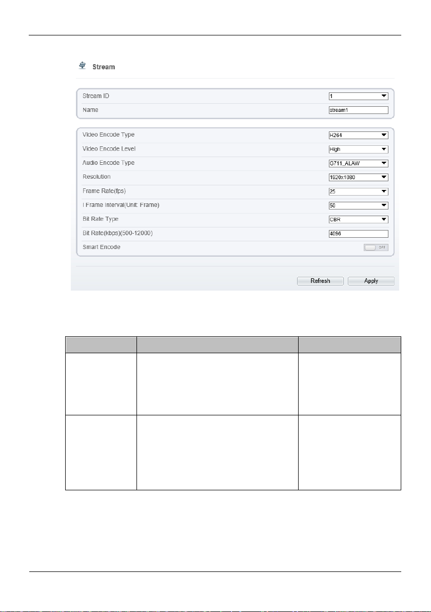
Step 1 Click Configuration > Stream > Base Stream.
The Stream Configuration page is displayed, as shown in Figure 4-8.
Page 26
Web Operation
High-Resolution IR Camera
User Manual
24
Issue V1.0 (2018-05-11)
Figure 4-8 Stream Configuration page
Parameter
Description
Setting
Stream ID
The device supports 3 streams.
Streams 1 and 2 use the H.264 codec.
The maximum resolution can be set
for streams 1.
[Setting method]
Select a value from the
drop-down list box.
Name
Stream name.
NOTE
The stream name is combined with
Chinese character, number, character and
underline.
[Setting method]
Enter a value manually.
The value cannot
exceed 32 bytes.
[Default value]
stream1
Step 2 Set the parameters according to Table 4-3.
Table 4-3 Stream configuration parameters
Page 27

High-Resolution IR Camera
User Manual
Web Operation
Issue V1.0 (2018-05-11) 25
Parameter
Description
Setting
Video Encode
Type
The video codec determines the image
quality and network bandwidth required
by a video. Currently, the following
codec standards are supported:
MJPEG
MJPEG is a standard intra-frame
compression codec. The compressed
image quality is good. No mosaic is
displayed on motion images. MJPEG
does not support proportional
compression and requires large storage
space. Recording and network
transmission occupy large hard disk
space and bandwidth. MJPEG is not
applicable to continuous recording for a
long period of time or network
transmission of videos. It can be used to
send alarm images.
H.264
H.264 consists of H.264 Base Profile,
H.264 Main Profile, and H.264 High
profile. The performance of H.264 High
Profile is higher than that of H.264
Main Profile, and the performance of
H.264 Main Profile is higher than that
of H.264 Base Profile. If a hardware
decoding device is used, select the
appropriate codec based on the decoding
performance of the device.
H.264 High Profile has the highest
requirements on the hardware
performance, and H.264 Base Profile
has the lowest requirements on the
hardware performance.
H.265
H.265 is the new video encoding
standard ,it's the improvement standard
from H.264. H.265 improves the
streams, encoding quality and algorithm
complexity to make configuration as
optimization.
[Setting method]
Select a value from the
drop-down list box.
[Default value]
H.264
NOTE
The H.264 High Profile
codec means high
requirements on the
hardware. If the hard
decoding capability is
low, use H.264 Main
Profile or H.264 Base
Profile.
Audio Encode
Type
The following audio codec standards are
supported:
[Setting method]
Select a value from the
Page 28

Web Operation
High-Resolution IR Camera
User Manual
26
Issue V1.0 (2018-05-11)
Parameter
Description
Setting
G711_ULAW: mainly used in North
America and Japan.
G711_ALAW: mainly used in Europe
and other areas.
RAW_PCM: codec of the original
audio data. This codec is often used
for platform data.
drop-down list box.
Resolution
A higher resolution means better image
quality.
NOTE
IP cameras support the different
resolutions based on the model.
[Setting method]
Select a value from the
drop-down list box.
Frame
Rate(fps)
The frame rate is used to measure
displayed frames. A higher frame rate
means smoother videos. A video whose
frame rate is higher than 22.5 f/s is
considered as smooth by human eyes.
Frame rates for different frequencies are
as follows:
50 Hz: 1–25 f/s
60 Hz: 1–30 f/s
NOTE
The frequency is set on the Device
Configuration > Camera page. The
biggest MJPEG coding format frame rate
is 12 frames per second.
[Setting method]
Select a value from the
drop-down list box.
I Frame
Interval(Unit:Fr
ame)
I frames do not require other frames to
decode.
A smaller I frame interval means better
video quality but higher bandwidth.
[Setting method]
Select a value from the
drop-down list box.
Bit Rate Type
The bit rate is the number of bits
transmitted per unit of time.
The following bit rate types are
supported:
Constant bit rate (CBR)
The compression speed is fast; however,
improper bit rate may cause vague
motion images.
Variable bit rate (VBR)
[Setting method]
Select a value from the
drop-down list box.
Page 29

High-Resolution IR Camera
User Manual
Web Operation
Issue V1.0 (2018-05-11) 27
Parameter
Description
Setting
The bit rate changes according to the
image complexity. The encoding
efficiency is high and the definition of
motion images can be ensured.
Bit Rate(500-
12000)
Indicates the value of the bit rate.
[Setting method]
Enter a value manually.
Image Quality
The video quality the camera output.
[Setting method]
Select a value from the
drop-down list box.
Parameter
Description
Setting
SVC Stream ID
The ID of the SVC stream.
[Setting method]
Select a value from the drop-
Step 3 Click Apply.
If the message "Apply success!" is displayed, and the system saves the settings.
If the message "Apply failed!" is displayed, you must apply for the Parameter
Configure permission from an administrator. For details, see4.10.1
4.4.2 Setting SVC Stream Parameters
Procedure
Step 1 Click Configuration > Stream > SVC Stream.
The SVC Stream page is displayed, as shown in Figure 4-9.
Figure 4-9 SVC Stream Configuration page
Step 2 Set the parameters according to Table 4-4.
Table 4-4 Stream configuration parameters
Page 30

Web Operation
High-Resolution IR Camera
User Manual
28
Issue V1.0 (2018-05-11)
Parameter
Description
Setting
down list box.
[Default value]
4
SVC Stream Name
Stream name.
NOTE
The stream name is combined
with Chinese character, number,
character and underline.
[Setting method]
Enter a value manually. The
value cannot exceed 32
bytes.
[Default value]
Stream4
Elementary Stream
ID
ID of the elementary stream.
[Setting method]
Select a value from the drop-
down list box.
P Frame Rate
The P frame rate of SVC stream
and elementary stream.
[Setting method]
Select a value from the drop-
down list box.
Step 3 Click Apply.
If the message "Apply success!" is displayed, and the system saves the settings.
If the message "Apply failed!" is displayed, you must apply for the Parameter
Configure permission from an administrator. For details, see 4.10.1
4.4.3 Region of Interest
Procedure
Step 1 Click Configuration > Stream > ROI.
The Region of Interest page is displayed, as shown in Figure 4-10.
Page 31

High-Resolution IR Camera
User Manual
Web Operation
Issue V1.0 (2018-05-11) 29
Figure 4-10 ROI Configuration page
Parameter
Description
Setting
Stream
Stream ID.
[Setting method]
Select a value from the
drop-down list box.
[Default value]
Stream1
Enable
Enable the ROI
[Setting method]
Click the button.
[Default value]
Step 2 Set the parameters according to Table 4-5
Table 4-5 ROI configuration parameters
Page 32

Web Operation
High-Resolution IR Camera
User Manual
30
Issue V1.0 (2018-05-11)
Parameter
Description
Setting
OFF
Area ID
ROI area ID
[Setting method]
Select a value from the
drop-down list box.
[Default value]
1
Level
Visual effect of ROI. The higher the
grade is, the more clearly areas inside and
the vaguer areas outside are..
[Setting method]
Select a value from the
drop-down list box.
[Default value]
5
Area Name
The marked name used for areas.
[Setting method]
Enter a value manually.
The value cannot exceed
32 bytes.
Step 3 Click Apply.
The message "Apply success!" is displayed, and the system saves the settings.
----End
4.4.4 Setting Local Network Parameters
Description
Local network parameters include:
IP protocol
IP address
Subnet mask
Default gateway
Dynamic Host Configuration Protocol (DHCP)
Preferred Domain Name System (DNS) server
Alternate DNS server
MTU
Procedure
Step 1 Choose Device Configuration > Local Network.
The Local Network page is displayed, as shown in Figure 4-11.
Page 33

High-Resolution IR Camera
User Manual
Web Operation
Issue V1.0 (2018-05-11) 31
Figure 4-11 Local Network page
Parameter
Description
Setting
IP Protocol
IPv4 is the IP protocol that uses an
address length of 32 bits.
[Setting method]
Select a value from the drop-
down list box.
[Default value]
IPv4
DHCP
The device automatically obtains
the IP address from the DHCP
server.
[Setting method]
Click the button on to enable
DHCP.
NOTE
To query the current IP address
of the device, you must query it
on the platform based on the
device name.
DHCP IP
IP address that the DHCP server
assigned to the device.
N/A
Step 2 Set the parameters according toTable 4-6.
Table 4-6 Local network parameters
Page 34

Web Operation
High-Resolution IR Camera
User Manual
32
Issue V1.0 (2018-05-11)
Parameter
Description
Setting
IP Address
Device IP address that can be set as
required.
[Setting method]
Enter a value manually.
[Default value]
192.168.1.64
Subnet Mask
Subnet mask of the network
adapter.
[Setting method]
Enter a value manually.
[Default value]
255.255.255.0
Default
Gateway
This parameter must be set if the
client accesses the device through a
gateway.
[Setting method]
Enter a value manually.
[Default value]
192.168.1.1
Preferred
DNS Server
IP address of a DNS server.
[Setting method]
Enter a value manually.
[Default value]
8.8.8.8
Alternate
DNS Server
IP address of a domain server.
If the preferred DNS server is
faulty, the device uses the alternate
DNS server to resolve domain
names.
[Setting method]
Enter a value manually.
[Default value]
blank
MTU
Set the maximum value of network
transmission data packets.
[Setting method]
Enter a value manually.
NOTE
The MTU value is range from
800 to 1500, the default value is
1500, Please do not change it
arbitrarily.
Step 3 Click Apply.
If the message "Apply success!" is displayed, and the system saves the settings.
The message "Set network parameter success, Please login system again" is
displayed. Use the new IP address to log in to the web management system.
If the message "Invalid IP Address", "Invalid Subnet Mask", "Invalid default
gateway", "Invalid primary DNS", or "Invalid space DNS" is displayed, set the
parameters correctly.
----End
Page 35

High-Resolution IR Camera
User Manual
Web Operation
Issue V1.0 (2018-05-11) 33
4.4.5 Configuring Device Ports
Parameter
Description
Setting
Control Port
Port used for audio and video transfer
and signaling interaction.
[Setting method]
Enter a value manually.
[Default value]
30001
HTTP Port
Port used in web access.
[Setting method]
Enter a value manually.
[Default value]
80
RTSP Port
RTSP protocol port.
[Setting method]
Enter a value manually.
[Default value]
554
Description
You must configure the HTTP port, control port, Real Time Streaming Protocol (RTSP)
port and RTMP port for device route mapping in a LAN.
Procedure
Step 1 Choose Configuration > Device > Device Port.
The Device Port page is displayed, as shown in Figure 4-12.
Figure 4-12 Device Port page
Step 2 Set the parameters according to Table 4-7.
Table 4-7 Device port parameters
Page 36

Web Operation
High-Resolution IR Camera
User Manual
34
Issue V1.0 (2018-05-11)
It’s not recommended to modify the control port, for details about the value ranges of the
control port, HTTP port and RTSP port, see the communication matrix.
Step 3 Click Apply.
If the message "Apply success!" is displayed, and the system saves the settings.
If the message "Invalid Control Port, Please input an integer between 1025 and
65535" is displayed, enter correct port numbers.
----End
4.4.6 Configuring the Date and Time
Description
On the Date and Time page, you can modify the date and time. Parameters that can be
set include:
Time zone and daylight saving time (DST)
Date and time
Network Time Protocol (NTP) server
Procedure
Step 1 Choose Configuration > Device > Date and Time.
The Date and Time page is displayed, as shown in Figure 4-13. Table 4-8describes the
parameters.
Page 37

High-Resolution IR Camera
User Manual
Web Operation
Issue V1.0 (2018-05-11) 35
Figure 4-13 Date and Time page
Parameter
Description
Setting
Time Zone
N/A
[Setting method]
Select a value from the
drop-down list box.
[Default value]
Greenwich mean time
Table 4-8 Date and Time parameters
Page 38

Web Operation
High-Resolution IR Camera
User Manual
36
Issue V1.0 (2018-05-11)
Parameter
Description
Setting
Daylight Saving
Time
When the DST start time arrives,
the device time automatically goes
forward one hour. When the DST
end time arrives, the device time
automatically goes backward one
hour.
NOTE
DST is the practice of advancing
clocks so that evenings have more
daylight and mornings have less.
Currently, about 110 countries in the
world use DST. Different countries
have different DST provisions. Since
March 27, 2011, Russia has started to
use permanent DST.
[Setting method]
Click the button on to
enable Daylight Saving
Time.
Device Time
Device display time.
[Setting method]
Synchronize the time
from the PC.
Enter a value manually.
Current PC Time
Time on the current PC.
N/A
Set Manually
Enables you to manually set the
device time.
[Setting method]
Click Set Manually and
set the date and time in the
format MM-DD-YYYY
HH:MM:SS.
NTP
IP address or domain name of the
NTP server.
[Setting method]
Click the button on to
enable NTP and enter a
value manually.
NTP Server Addr
The NTP server IP.
[Setting method]
Enter a value manually.
NTP Port
Port number of the NTP server.
[Setting method]
Enter a value manually.
[Default value]
123
Check the time
interval( at least
10s)
Set time interval to check if the
device time synchronizes with the
NTP server time.
[Setting method]
Enter a value manually.
[Default value]
3600
Page 39

High-Resolution IR Camera
User Manual
Web Operation
Issue V1.0 (2018-05-11) 37
Step 2 Select a time zone from the Time Zone drop-down list box.
Step 3 (Optional) Click the button on to enable Daylight Saving Time and specify the DST
start time and end time.
Step 4 Modify the device time.
Synchronizing time from the PC
Click Current PC Time.
Manually setting the device time
− Click Set Manually.
A time setting control is displayed.
− Set the date and time.
Step 5 Configure the NTP.
1. Click the button on to enable NTP.
2. Enter the IP address or domain name of the NTP server, the port number and the
time interval.
Step 6 Click .
The message "Apply success!" is displayed and the system saves the settings.
----End
4.4.7 Setting the Channel Name, Video System, and Source
Resolution
Procedure
Step 1 Choose Configuration > Device > Camera.
The Camera page is displayed, as shown in Figure 4-14. Table 4-9 describes the
parameters.
Figure 4-14 Camera page
Page 40

Web Operation
High-Resolution IR Camera
User Manual
38
Issue V1.0 (2018-05-11)
Parameter
Description
Setting
Channel Name
Channel name within the
length of 0 to 32 bytes.
[Setting method]
Enter a value manually.
Video System
The options are as follows:
PAL: Used in Europe
and China mainland.
NTSC: Used in USA
and Japan.
[Setting method]
Select a value from the
drop-down list box.
[Default value]
PAL
NOTE
Whether the video system
can be changed depends on
the device model.
Video Refresh Frequency
The options are as follows:
50 Hz: corresponds to
the PAL system.
60 Hz: corresponds to
NTSC system.
[Setting method]
Corresponds to the video
system.
Table 4-9 Camera parameters
Step 2 Enter a channel name.
The channel name must be within the length of 0 to 32 bytes, it is combined with digital and
character (except for some special character).
Step 3 Click .
The message "Apply success!" is displayed.
If the video system is modified, the message "The device will be restart, are you sure to
modify?" is displayed, and the system automatically saves the settings. The settings take
effect after the device restarts.
----End
4.4.8 Setting OSD Parameters
Description
The on-screen display (OSD) function allows you to display the device name, channel
ID and name, time, and other customized contents on videos.
Page 41

High-Resolution IR Camera
User Manual
Web Operation
Issue V1.0 (2018-05-11) 39
When the resolution is D1 and CIF, the OSD customized in web interface can show
at most 22 words normally.
The OSD support simplified Chinese, English, digital and some special character
only.
Procedure
Step 1 Choose Configuration > Device > OSD.
The OSD page is displayed, as shown in Figure 4-15.
Figure 4-15 OSD page
Step 2 Set the parameters according to Table 4-10.
The size of characters that can be displayed in a row or column varies according to the
resolution. When the OSD font is auto:
Page 42

Web Operation
High-Resolution IR Camera
User Manual
40
Issue V1.0 (2018-05-11)
Parameter
Description
Setting
Time
Indicates whether to
display the time.
[Setting method]
Tick the time.
Custom OSD
Enables you to enter a line
of characters.
[Setting method]
1. Tick the custom
OSD list.
2. Enter the characters.
3. Click to save
the value.
Time Format
Format in which the time
is displayed.
[Setting method]
Select a value from the
drop-down list box.
[Default value]
YYYY-MM-DD
hh:mm:ss ww
Font Color
Set the font color.
[Setting method]
Select a value from the
drop-down list box.
[Default value]
Blank
Font Size
Set the font size.
[Setting method]
Select a value from the
drop-down list box.
[Default value]
Mid
Font Transparency
Set the font transparency.
[Setting method]
Select a value from the
drop-down list box.
[Default value]
Opaque
Font on lighted back
Enable the font on lighted
[Setting method]
If the resolution is 1920 x 1080 and the size of each character is 48 x 48, then the
maximum row of OSD is 22 (1080/48), and the maximum column is 40 (1920/48);
If the resolution is 704 x 576 and the size of each character is 32 x 32, then the maximum
row of OSD is 18 (576/32), and the maximum column is 22 (704/32);
If the resolution is 640 x 360 and the size of each character is 16 x 16, the maximum row
of OSD is 22(360/16) characters, and a maximum column is 40(640/16).
Table 4-10 OSD parameters
Page 43

High-Resolution IR Camera
User Manual
Web Operation
Issue V1.0 (2018-05-11) 41
Parameter
Description
Setting
back.
Click the button on to
enable Font on lighted
back.
Device Name
Indicates whether to
display the device name.
[Setting method]
Click the button on to
enable Device Name
Step 3 Click Apply.
The message "Apply success!" is displayed And the system saves the settings.
----End
4.4.9 System Service
Procedure
Step 1 Choose Configuration > Device > System.
The System Service page is displayed, as shown in Figure 4-16.
Figure 4-16 System Service page
Step 2 Select a language from the Language drop-down list box.
Step 3 Click , the message "Apply success" is displayed.
Step 4 Click OK, the system saves the settings.
Step 5 Select a Web Mode from the Web Mode drop-down list box.
Step 6 Click , the message "This operation will lead to the device to restart, continue?”
is displayed.
Page 44

Web Operation
High-Resolution IR Camera
User Manual
42
Issue V1.0 (2018-05-11)
Step 7 Click OK, the device restarts and saves the settings automatically.
----End
4.5 Configuring the Alarm Function
4.5.1 Setting Disk Alarm Parameters
Procedure
Step 1 Choose Configuration >Alarm > Disk Alarm.
The Disk Alarm page is displayed, as shown in Figure 4-17.
Figure 4-17 Disk Alarm page
Step 2 Click the button on to enable disk alarm.
Step 3 Configure the alarm interval parameters.
Step 4 Click Apply.
The message "Apply succeed" is displayed and the system saves the settings.
----End
4.5.2 Setting Network Alarm Parameters
Procedure
Step 1 Choose Configuration >Alarm > Network Alarm.
The Network Alarm page is displayed, as shown in Figure 4-18.
Page 45

High-Resolution IR Camera
User Manual
Web Operation
Issue V1.0 (2018-05-11) 43
Figure 4-18 Network Alarm page
Step 2 Click the button on to enable exceptional alarm.
Step 3 Configure the network exceptional alarm interval.
Step 4 Tick the Output Channel number.
Step 5 Click the button on to enable Alarm Record alarm.
Step 6 Click Apply.
The message "Apply succeed" is displayed and the system saves the settings.
----End
4.5.3 Setting Motion Alarm Parameters
Description
On the Motion Alarm page, you can perform the following operations:
Enable the motion alarm function.
Set the motion alarm interval.
Set the motion detection area.
Set motion alarm the sensitivity
Configure the motion alarm output channel.
When the alarm output function is enabled and the camera detects that an object
moves into the motion detection area within the schedule time, the camera
generates an alarm and triggers linkage alarm output.
Enable the Alarm record.
Enable SMTP.
Page 46

Web Operation
High-Resolution IR Camera
User Manual
44
Issue V1.0 (2018-05-11)
Enable FTP Upload.
Procedure
Step 1 Choose Configuration >Alarm > Motion Alarm.
The Motion Alarm page is displayed, as shown in Figure 4-19.
Figure 4-19 Motion Alarm page
Step 2 Click the button on to enable motion alarm.
Step 3 Configure the motion interval.
Step 4 Configure the sensitivity.
Step 5 Configure the schedule time setting.
Method 1:Click left mouse button to select any time point within 0:00-24:00 from
Monday to Sunday as shown in Figure 4-19.
Method 2:Hold down the left mouse button, drag and release mouse to select the
schedule within 0:00-24:00 from Monday to Sunday.
Page 47

High-Resolution IR Camera
User Manual
Web Operation
Issue V1.0 (2018-05-11) 45
NOTE
When you select time by dragging the cursor, the cursor cannot be moved out of the time
area. Otherwise, no time can be selected.
Method 3:Click in the schedule page to select the whole day or whole week.
Deleting deployment time: Click again or inverse selection to delete the selected
schedule.
Step 6 Configure the detection area.
Press and hold the left mouse button, and drag in the video area to draw a detection
area, as shown in Figure 4-20.
Figure 4-20 Motion Area Setting page
Click Clear to delete a detection area.
Step 7 Click Apply.
The message "Apply succeed" is displayed. the system saves the settings.
----End
4.5.4 Setting push message Parameters
Description
When enable push message button, the alarm information will be pushed to app if the
device is managed by App.
Page 48

Web Operation
High-Resolution IR Camera
User Manual
46
Issue V1.0 (2018-05-11)
Procedure
Step 1 Choose Configuration >Alarm > Push Message.
The Push Message page is displayed, as shown in Figure 4-21.
Figure 4-21 Push message page
Step 2 Click the button on to enable push message.
Step 3 Click Apply.
The message "Apply succeed!" is displayed, and the system saves the settings.
----End
4.6 Configuring the Recording Function
4.6.1 Configuring a Recording Policy
You can configure the scheduled recording function, alarm recording function,
recording quality, and recording rules.
Procedure
Step 1 Choose Configuration > Device Record > Record Policy.
The Record Policy page is displayed, as shown in Figure 4-22.
Page 49

High-Resolution IR Camera
User Manual
Web Operation
Issue V1.0 (2018-05-11) 47
Figure 4-22 Record Policy page
Parameter
Description
Setting
Schedule
Record
Enables schedule record that you can
configure the time policy.
[Setting method]
Click the button on to enable
schedule record.
[Default value]
OFF
Post Record
Recording duration (in seconds) after
an alarm is generated.
[Setting method]
Enter a value manually.
Record
Rule
Rule for saving recordings. The options
are as follows:
Cycle Store: Saves recordings in
cycles.
Save Days: Duration (in days) for
saving a recording. The duration can
be a maximum of 99999 days.
NOTE
The value 0 indicates that recordings are
not overwritten.
[Setting method]
Select a value from the drop-
down list box.
Step 2 Set the parameters according to Table 4-11.
Table 4-11 Recording policy parameters
Page 50

Web Operation
High-Resolution IR Camera
User Manual
48
Issue V1.0 (2018-05-11)
Parameter
Description
Setting
Stream
Name
Name of the stream.
[Setting method]
Select a value from the drop-
down list box.
Step 3 Configure a recording plan.
You can configure the system to record videos around the clock or in schedule.
For details about how to set Schedule, see 4.5.3 Step 5.
Step 4 Click Apply.
If the message "Apply success!" is displayed, the system saves the settings.
If other information is displayed, set the parameters correctly.
-----End
4.6.2 Configuring a Recording Directory
Description
Recordings can be stored in a NAS.
Procedure
Step 1 Choose Configuration > Device Record > Record Directory.
The Record Directory page is displayed, as shown in Figure 4-23.
Page 51

High-Resolution IR Camera
User Manual
Web Operation
Issue V1.0 (2018-05-11) 49
Figure 4-23 Record Directory page
Parameter
Description
Setting
Disk Type
Recording directory type, which can be a
NAS.
[Setting method]
The parameter cannot
be set manually.
Disk ID
Indicates the Disk ID.
Group ID
Indicates the group HID.
Enable
Indicates whether to enable the recording
directory.
Total Space
Total disk space.
Usable Space
Maximum disk space read automatically.
Alarm
Threshold (%)
The camera will alarm when used Space
achieves the alarm threshold.
State
Status of the connection between the
current camera and recording directory
detected automatically.
Step 2 Set the parameters according to Table 4-12.
Table 4-12 Recording directory parameters
Page 52

Web Operation
High-Resolution IR Camera
User Manual
50
Issue V1.0 (2018-05-11)
4.6.3 Configuring the SD Card or NAS Recording
Parameter
Description
Setting
NAS
Enable NAS to enable record.
[Setting method]
Click button to enable
NAS.
IP Address
IP address of NAS
[Setting method]
Enter a value manually.
Path
Path of NAS.
User Name
N/A
Password
Confirm
File System
[Setting method]
Select a value from the
drop-down list box.
Procedure
Step 1 Choose Configuration > Device Record > Record Directory.
Step 2 Click Modify.
The Record Path Modify page is displayed, as shown in Figure 4-24.
Figure 4-24 SD card Record Path Modify page
Step 3 Set the parameters according to Table 4-13.
Table 4-13 SD card recording parameters
Page 53

High-Resolution IR Camera
User Manual
Web Operation
Issue V1.0 (2018-05-11) 51
Step 4 Click Apply.
The message "Apply success!" is displayed, and the system saves the settings.
-----End
4.7 Configuring the Privacy Mask Function
Procedure
Step 1 Choose Configuration > Privacy Masking.
The Privacy Masking page is displayed, as shown in Figure 4-25.
Figure 4-25 Privacy Masking page
Step 2 Press and hold the left mouse button, and drag on the preview image to cover the part
to be masked.
Page 54

Web Operation
High-Resolution IR Camera
User Manual
52
Issue V1.0 (2018-05-11)
Parameter
Description
Setting
ID
ID of Privacy Masking.
N/A
Name
Name of privacy Masking.
[Setting method]
Click the name and enter a value
manually.
[Default value]
Blank
Type
Type of privacy masking.
[Setting method]
Select a value from the drop-down list
box.
[Default value]
Color Block
Color
Color of privacy masking.
[Setting method]
Select a value from the drop-down list
box.
[Default value]
Black
Enable
Indicates whether to enable
the privacy masking.
[Setting method]
Select a value from the drop-down list
box.
[Default value]
Yes
Delete
Delete a privacy masking.
[Setting method]
1. 1.Select a privacy masking from
the Privacy Masking List.
2. 2.Click Delete, the privacy
masking is deleted successfully
The maximum percentage of an image that can be masked depends on the device model.
Read the tip displayed on the page. A maximum of five areas can be masked.
You can click Reset to configure the masked areas again.
Step 3 Set the parameters according to Table 4-14.
Table 4-14 Privacy Masking parameters
Page 55

High-Resolution IR Camera
User Manual
Web Operation
Issue V1.0 (2018-05-11) 53
Parameter
Description
Setting
Modify
Modify a privacy masking.
[Setting method]
1. Select a privacy masking from
the Privacy Masking List.
2. Click a parameter and modify it.
3. Click Modify, the privacy
masking is modified
successfully
Step 4 Click Apply.
The message "Apply success!" is displayed, and the system saves the settings.
----End
4.8 Configuring the Network Service
4.8.1 Setting 802.1x Parameters
Preparation
802.1x authentication must be configured on the access port, which controls to access
network resources for the connected user devices on the port.
Procedure
Step 1 Choose Configuration > Network Service > 802.1x.
The 802.1x page is displayed, as shown in Figure 4-26.
Figure 4-26 802.1x page
Page 56

Web Operation
High-Resolution IR Camera
User Manual
54
Issue V1.0 (2018-05-11)
Step 2 Click the button on to enable 802.1x.
Parameter
Description
Setting
DDNS
Indicates whether to enable
the DDNS service.
[Setting method]
Click the button on to enable DDNS.
[Default value]
OFF
Step 3 Enter the account name.
Step 4 Enter the password and confirm password..
Step 5 Click Apply.
Step 6 The message "Apply success!" is displayed, and the system saves the settings.
----End
4.8.2 Setting DDNS Parameters
Preparation
Connect the specified camera to the Internet, and obtain the user name and password
for logging into the Dynamic Domain Name System (DDNS) server.
Procedure
Step 1 Choose Configuration > Network Service > DDNS.
The DDNS page is displayed, as shown in Figure 4-27.
Figure 4-27 DDNS page
Step 2 Click the button on to enable DDNS.
Step 3 Set the parameters according to Table 4-15.
Table 4-15 DDNS parameters
Page 57

High-Resolution IR Camera
User Manual
Web Operation
Issue V1.0 (2018-05-11) 55
Parameter
Description
Setting
Provider
DDNS service provider.
Currently, only 3322 and
DynDns are supported.
[Setting method]
Select a value from the drop-down
list box.
[Default value]
WBoxDDNS
NOTE
Set this parameter based on the site
requirements.
Host Name
Host name customized by a
user.
[Setting method]
Enter a value manually.
[Default value]
Blank
Test DDNS
Test if the device connects to
DDNS successfully.
[Setting method]
Click Test, if the device connects to
DDNS successfully, the message
“Test CGI alarm success” is
displayed.
Step 4 Click Apply.
If the message "Apply success!" is displayed, and the system saves the settings.
If other information is displayed, set the parameters correctly.
----End
4.8.3 Setting PPPoE Parameters
Preparation
Obtain the PPPoE user name and password from the network carrier.
Description
If a PPPoE connection is used, you need to enter the user name and password on the
PPPoE page. After you restart the device, the PPPoE settings take effect and the device
obtains a public IP address.
Procedure
Step 1 Choose Configuration > Network Service > PPPoE.
The PPPoE page is displayed, as shown in Figure 4-28.
Page 58

Web Operation
High-Resolution IR Camera
User Manual
56
Issue V1.0 (2018-05-11)
Figure 4-28 PPPoE page
Parameter
Description
Setting
PPPoE
Indicates whether to enable the
PPPoE service.
[Setting method]
Click the button on.
[Default value]
OFF
Accounts
User name of PPPoE provided by the
network carrier.
[Setting method]
Enter a value manually.
Password
Password of PPPoE provided by the
network carrier.
[Setting method]
Enter a value manually.
Step 2 Click the button on to enable PPPoE.
Step 3 Set the parameters according to Table 4-16.
Table 4-16 PPPoE parameters
Step 4 Click Apply.
If the message "Apply success!" is displayed, and the system saves the settings.
If other information is displayed, set the parameters correctly.
----End
4.8.4 Setting Port Mapping Parameters
Description
With port forwarding can setup the connection between privacy network and public
network. Enable the port forwarding to access the privacy network devices from public
network.
Page 59

High-Resolution IR Camera
User Manual
Web Operation
Issue V1.0 (2018-05-11) 57
Procedure
Parameter
Description
Setting
Port Mapping
Indicates whether to enable the
Port Mapping service.
[Setting method]
Click the button on.
[Default value]
OFF
Map Mode
Mode of port mapping, includes
auto and manual.
[[Setting method]
Select a value from the
drop-down list box.
[Default value]
Auto
Port Type
Port Type includes: HTTP, RTSP
and Control
N/A
Step 1 Choose Configuration > Network Service > Port Mapping.
The Port Mapping page is displayed, as shown in Figure 4-29.
Figure 4-29 Port Mapping page
Step 2 Click the button on to enable Port Mapping.
Step 3 Set the parameters according to Table 4-17.
Table 4-17 Port mapping parameters
Page 60

Web Operation
High-Resolution IR Camera
User Manual
58
Issue V1.0 (2018-05-11)
Outside Port
Port of outside network.
[Setting method]
Enter a value manually in
map mode.
Outside IP Address
IP address of outside network.
N/A
State
Mapping status
N/A
Step 4 Click Apply.
If the message "Apply success!" is displayed, and the system saves the settings.
If other information is displayed, set the parameters correctly.
----End
4.8.5 Setting SMTP Parameters
Description
If the Simple Mail Transfer Protocol (SMTP) function is enabled, the device
automatically sends JPG images and alarm information to specified email addresses
when an alarm is generated.
Procedure
Step 1 Choose Configuration > Network Service > SMTP.
The SMTP page is displayed, as shown in Figure 4-30.
Page 61

High-Resolution IR Camera
User Manual
Web Operation
Issue V1.0 (2018-05-11) 59
Figure 4-30 SMTP page
Parameter
Description
Setting
SMTP Server
Address
IP address of the SMTP server.
[Setting method]
Enter a value manually.
SMTP Server
Port
Port number of the SMTP server.
[Setting method]
Enter a value manually.
[Default value]
25
User Name
User name of the mailbox for sending
emails.
[Setting method]
Enter a value manually.
Password
Password of the mailbox for sending
emails.
[Setting method]
Enter a value manually.
Step 2 Set the parameters according to Table 4-18.
Parameters marked with are mandatory.
Table 4-18 SMTP parameters
Page 62

Web Operation
High-Resolution IR Camera
User Manual
60
Issue V1.0 (2018-05-11)
Parameter
Description
Setting
Sender Email Address
Mailbox for sending emails.
[Setting method]
Enter a value manually.
Recipient_Email_Address
1
(Mandatory) Email address of recipient
1.
[Setting method]
Enter a value manually.
Recipient_Email_Address
2
(Optional) Email address of recipient 2.
Recipient_Email_Address
3
(Optional) Email address of recipient 3.
Recipient_Email_Address
4
(Optional) Email address of recipient 4.
Recipient_Email_Address
5
(Optional) Email address of recipient 5.
Attachment
Image
Quality
A higher-quality image means more
storage space. Set this parameter based
on the site requirement.
N/A
Transport
Mode
Email encryption mode. Set this
parameter based on the encryption
modes supported by the SMTP server.
[Setting method]
Select a value from the
drop-down list box.
[Default value]
No Encrypted
Step 3 Click Apply.
If the message "Apply success!" is displayed, and the system saves the settings.
If other information is displayed, set the parameters correctly.
----End
4.8.6 Setting FTP Parameters
Description
If the File Transfer Protocol (FTP) button is enabled, the device automatically sends the
snapped alarm JPG images to specified FTP server.
Procedure
Step 1 Choose Configuration > Network Service > FTP.
Page 63

High-Resolution IR Camera
User Manual
Web Operation
Issue V1.0 (2018-05-11) 61
The FTP page is displayed, as shown in Figure 4-31.
Parameter
Description
Setting
FTP
Upload
Indicates whether to enable the
FTP service.
[Setting method]
Click the button on.
[Default value]
OFF
FTP
Address
IP address of FTP server.
[Setting method]
Enter a value manually.
FTP Port
Port of FTP server.
[Setting method]
N/A
[Default value]
21
Account
FTP server account.
[Setting method]
Enter a value manually.
Password
FTP server Password.
[Setting method]
Enter a value manually.
FTP Path
FTP Path to save the JPG image.
[Setting method]
Enter a value manually.
Figure 4-31 FTP page
Step 2 Click the button on to enable FTP.
Step 3 Set the parameters according to Table 4-19.
Table 4-19 FTP parameters
Page 64

Web Operation
High-Resolution IR Camera
User Manual
62
Issue V1.0 (2018-05-11)
Parameter
Description
Setting
Image
Quality
A higher-quality image means
more storage space. Set this
parameter based on the site
requirement.
[Setting method]
Select a value from the drop-
down list box.
[Default value]
Mid
Step 4 Click Apply.
If the message "Apply success!" is displayed, and the system saves the settings.
If other information is displayed, set the parameters correctly.
----End
4.8.7 Setting IP Filter Parameters
Description
Set the IP address in specified network segment to allow access or prohibit access.
Procedure
Step 1 Choose Configuration > Network Service > IP Filter.
The IP Filter page is displayed, as shown in Figure 4-32.
Page 65

High-Resolution IR Camera
User Manual
Web Operation
Issue V1.0 (2018-05-11) 63
Figure 4-32 IP Filter page
Parameter
Description
Setting
IP Filter
Indicates whether to enable the
IP Filter.
[Setting method]
Click the button on.
[Default value]
OFF
Rule Type
IP filter type, includes black list
and white list.
[Setting method]
Select a value from the drop-down
list box.
[Default value]
Black List
Step 2 Click the button on to enable IP Filter.
Step 3 Set the parameters according to Table 4-20
Table 4-20 IP Filter parameters
Page 66

Web Operation
High-Resolution IR Camera
User Manual
64
Issue V1.0 (2018-05-11)
Parameter
Description
Setting
Black List
Specified network segment to
allow access
[Setting method]
1. Click to enter the add
black/white list page, as
shown in Figure 4-33
2. Enter Begin IP Address.
3. Enter End IP Address.
4. Enter Description.
5. Click OK, the black list
added successfully.
White List
Specified network segment to
prohibit access
[Setting method]
1. Click to enter the add
black/white list page, as
shown in Figure 4-33
2. Enter Begin IP Address.
3. Enter End IP Address.
4. Enter Description.
5. Click OK, the white list
added successfully.
Page 67

High-Resolution IR Camera
User Manual
Web Operation
Issue V1.0 (2018-05-11) 65
Figure 4-33 Add IP Filter page
Step 4 Click Apply.
The message "Apply success!" is displayed, and the system saves the settings.
----End
4.8.8 Setting CGI Alarm Service Center Parameters
Description
Device will push the alarm message by CGI with Start URL and End URL, and send to
data to CGI Server by HTTP protocol. CGI alarm message is the head of User-Agent of
HTTP. Use HTTP protocol get and send to CGI Server. When need to integrate the CGI
alarm message, need to resolve the HTTP Head "User-Agent" to get the data of CGI
alarm message.
Procedure
Step 1 Choose Configuration > Network Service > CGI Alarm Service Center.
The CGI Alarm Service Center page is displayed, as shown in Figure 4-34.
Page 68

Web Operation
High-Resolution IR Camera
User Manual
66
Issue V1.0 (2018-05-11)
Figure 4-34 CGI Alarm Service Center page
Parameter
Description
Setting
CGI Alarm
Indicates whether to enable the
CGI Alarm.
[Setting method]
Click the button on.
[Default value]
OFF
Name
Name of CGI Alarm.
[Setting method]
Enter a value manually.
Type
Type of CGI Alarm.
[Setting method]
Select a value from the drop-down
list box.
[Default value]
HTTP
Step 2 Click the button on to enable CGI Alarm.
Step 3 Set the parameters according to Table 4-21.
Table 4-21 CGI Alarm Service Center parameters
Page 69

High-Resolution IR Camera
User Manual
Web Operation
Issue V1.0 (2018-05-11) 67
Parameter
Description
Setting
URL Start
Push the alarm message by CGI
with start URL
[Setting method]
Enter a value manually.
For example:
http://192.168.35.74:80/MajorAlar
mType&MinorAlarmType&Source
Name&DeviceID&DeviceIP&Alar
mTime& Description
URL End
Push the alarm message by CGI
with end URL
[Setting method]
Enter a value manually.
For example:
http://192.168.35.74:80/MajorAlar
mType&MinorAlarmType&Source
Name&DeviceID&DeviceIP&Alar
mTime&Description
User Name
User name of device.
[Setting method]
Enter a value manually.
Password
Password of device.
[Setting method]
Enter a value manually.
Proxy
Setting
Indicates whether to enable the
Proxy.
Forwarder server of CGI alarm to
forward the CGI alarm.
[Setting method]
Click the button on.
[Default value]
OFF
Address
IP address of Forwarder server.
[Setting method]
Enter a value manually.
Port
Port of Forwarder server.
[Setting method]
Enter a value manually.
platform
User Name
User name of forwarder server.
[Setting method]
Enter a value manually.
platform
Password
Password of forwarder server.
[Setting method]
Enter a value manually.
Test the
connection
to the
specified
HTTP
server
Test if the device connects to the
proxy successfully.
[Setting method]
Click Test, if the device connects to
the proxy successfully, the message
“Test CGI alarm success” is
displayed.
Step 4 Click Apply.
Page 70

Web Operation
High-Resolution IR Camera
User Manual
68
Issue V1.0 (2018-05-11)
The message "Apply success!" is displayed, and the system saves the settings.
----End
4.8.9 Setting SNMP Parameters
Description
Simple Network Management Protocol (SNMP) is an Internet Standard protocol,
supports SNMP v1, SNMPv2c and SNMPv3 network protocol. Choose the proper
SNMP protocol version and set the SNMP protocol parameter to collect and organize
information about managed devices on IP networks.
Procedure
Step 1 Choose Configuration > Network Service > SNMP.
The SNMP page is displayed, as shown in Figure 4-35.
Page 71

High-Resolution IR Camera
User Manual
Web Operation
Issue V1.0 (2018-05-11) 69
Figure 4-35 SNMP page
Step 2 Click the button on to enable SNMPv1, SNMPv2C and SNMPv3.
Table 4-22 Set the parameters according to Table 4-23.
Page 72

Web Operation
High-Resolution IR Camera
User Manual
70
Issue V1.0 (2018-05-11)
Parameter
Description
Setting
SNMPv1
Version of SNMP.
SNMPv1 and SNMPv2c use communities to
establish trust between managers and agents.
Agents support three community names,
write community, read community and trap.
[Setting method]
Click the button on.
[Default value]
OFF
SNMPv2c
Write
Community
Name of write community.
The write community only can modify data.
[Setting method]
Enter a value manually.
Read
Community
Name of read community.
The write community only can read data.
Trap
Address
IP address of the trap.
Trap Port
Management port of accepting message from
trap.
Trap
Community
community string of trap.
The trap community string allows the
manager to receive asynchronous information
from the agent.
SNMPv3
Version of SNMP.
SNMPv3 uses community strings, but allows
for secure authentication and communication
between SNMP manager and agent.
[Setting method]
Click the button on.
[Default value]
OFF
Read
Security
Name
Name of read security.
[Setting method]
Enter a value manually.
Write
Security
Name
Name of write security.
Security
Level
Security Level between SNMP manager and
agent, includes three levels:
Noauth: No authentication and no encryption
Auth: Authentication but no encryption
Priv: Authentication and encryption
[Setting method]
Select a value from the
drop-down list box.
[Default value]
Blank
Auth
Algorithm
Authentication Algorithm, includes MD5and
SHA.
[Setting method]
Select a value from the
drop-down list box.
[Default value]
Blank
Table 4-23 SNMP parameters
Page 73

High-Resolution IR Camera
User Manual
Web Operation
Issue V1.0 (2018-05-11) 71
Parameter
Description
Setting
Auth
Password
Authentication password.
[Setting method]
Enter a value manually.
Encry
Algorithm
Encryption Algorithm, includes DES and
AES.
[Setting method]
Select a value from the
drop-down list box.
[Default value]
Blank
Encry
Password
Encryption password.
[Setting method]
Enter a value manually.
SNMP Port
Port of SNMP.
[Setting method]
Enter a value manually.
[Default value]
161
Step 3 Click Apply.
The message "Apply success!" is displayed, and the system saves the settings.
----End
4.9 Privilege Manager
Description
You can add, modify, and delete a user in privilege manager page.
Procedure
Step 1 Choose Configuration > Privilege Manager > User.
The User page is displayed, as shown in Figure 4-36. Table 4-24 describes the
parameters.
Page 74

Web Operation
High-Resolution IR Camera
User Manual
72
Issue V1.0 (2018-05-11)
Figure 4-36 User page
Parameter
Description
Setting
ID
User ID
N/A
User Name
User name for logging in to the camera.
[Setting method]
Select a value from the
drop-down list box.
Groups
Permission group where a user belongs.
The default permission groups are Super
Admin, Administrators, Operator, and
Media user. Their permissions are
described as follows:
Super Admin: Includes all privileges.
Administrators: Live Video, Video
Control, PTZ control, Audio, Playback,
Backup, Record Policy, Disk
Configure, Privilege Manage,
Parameter Configure, System
Maintenance and Log,
Operator: System Maintenance,
Parameter Configure, playback, Live
Video and Video Control.
Media user: Live Video
[Setting method]
Click Add, then select a
value from the drop
down list box.
Table 4-24 User parameters
Page 75

High-Resolution IR Camera
User Manual
Web Operation
Issue V1.0 (2018-05-11) 73
Parameter
Description
Setting
Notes
Notes of the User.
[Setting method]
Click Add, then enter a
value manually.
Operate
The operation of the user, includes view
user, modify user and delete user.
NOTE
Super Admin can be viewed only.
[Setting method]
Click the icon as
required.
Function
Procedure
Description
Add
1. Click Add.
The Add User page is displayed, as shown in
Figure 4-37.
2. Enter a user name, password, confirm
password.
3. Select a group from the drop down list box.
4. Enter the notes (Optional).
5. Check the privilege.
6. Click OK.
The user is added successfully.
Add an
administrator or
a common user
as shown in
Figure 4-37.
Modify
1. Click .
The Modify User page is displayed.
2. Modify the user name, password, group or
privilege.
3. Click OK.
The user is modified successfully. The User page
is displayed.
Modify the user
name, password,
group or
privilege.
Step 2 Add, modify, or delete a user as required.
Table 4-25 describes the operations.
Table 4-25 Operation description
Page 76

Web Operation
High-Resolution IR Camera
User Manual
74
Issue V1.0 (2018-05-11)
Function
Procedure
Description
Delete
Select the user from the User list. Click , the
message “Confirm to delete?” is displayed, click OK,
then the group is deleted successfully.
Delete a user.
Figure 4-37 Add user page
----End
Page 77

High-Resolution IR Camera
User Manual
Web Operation
Issue V1.0 (2018-05-11) 75
4.10 Configuring Protocol Parameters
Parameter
Description
Protocol Name
Type of the access protocol.
Protocol Version
Version number of the access protocol.
Protocol Software Version
Software version number of the access protocol.
RTSP Rule
URL rule of Real Time Streaming Protocol.
RTSP Example
URL example of Real Time Streaming Protocol.
4.10.1 Checking Protocol Information
Description
You can view the existing protocol name and version number of the current device on
the Configuration > Protocol > Protocol Info page, as shown in Figure 4-38. Table 426 describes the protocol-related parameters.
Figure 4-38 Protocol Info page
Table 4-26 Protocol-related parameters
4.10.2 Setting Security Authentication
Description
When an ONVIF-compliant device connects to the platform, you must authenticate the
user name and password to ensure the connection security.
Page 78

Web Operation
High-Resolution IR Camera
User Manual
76
Issue V1.0 (2018-05-11)
Procedure
Parameter
Description
Setting
User Verification
When you select the User Verification
check box, the user name and password
must be the same as those for logging in
to the device web page.
NOTE
The default user name is admin, and the
default password is admin.
[Setting method]
Click the button on
to enable User
Verification.
Step 1 Choose Configuration > Protocol > Security.
The Security page is displayed as shown in Figure 4-39. Table 4-27 describes the
parameters on the Security page.
Figure 4-39 Security page
Table 4-27 Parameter description
Step 2 Click Apply.
A dialog box is displayed, indicating the parameter configuration success. To make the
configuration take effect, click Confirm to restart the device.
----End
4.10.3 Setting Multicast Parameters
Description
You can set multicast IP, video port, audio port and source port in multicast parameter
page.
Procedure
Step 1 Choose Configuration > Protocol > Multicast Param.
The Multicast Param page is displayed as shown in Figure 4-40. Table 4-28 describes
the parameters on the Multicast Param page.
Page 79

High-Resolution IR Camera
User Manual
Web Operation
Issue V1.0 (2018-05-11) 77
Figure 4-40 Multicast Param page
Parameter
Description
Setting
Stream ID
ID of stream.
[Setting method]
Select a value from the drop-
list box.
[Default value]
1
IP
IP address that receive multicast data.
[Setting method]
Enter a value manually.
[Default value]
238.255.255.255
Video Port
Port that receive video data.
[Setting method]
Enter a value manually.
[Default value]
25330
Source Port
Port that receive source data.
[Setting method]
Enter a value manually.
[Default value]
25530
Table 4-28 Parameter description
Step 2 Click Apply.
The message "Apply success, effective after restart!" is displayed, when the device
restarts, the system will save the settings.
----End
Page 80

Web Operation
High-Resolution IR Camera
User Manual
78
Issue V1.0 (2018-05-11)
4.11 Querying Operation Logs
Description
Operation logs record user operations and scheduled task commands during the
running of the device. Operation logs can be classified into the following types:
permission management, system maintenance, device configuration, recording
operation, video control, and real-time video.
4.11.2 Querying Operation Logs
Procedure
Step 1 Choose Configuration > Device Log > Operation Log.
The Operation Log page is displayed, as shown in Figure 4-41.
Figure 4-41 Operation Log page
Step 2 Set the search criteria.
1. Select the type of operation logs to be queried from the System Log drop-down
list box.
2. Click the Begin Time and End Time text boxes respectively.
A time setting control is displayed.
Page 81

High-Resolution IR Camera
User Manual
Web Operation
Issue V1.0 (2018-05-11) 79
3. Set the start time and end time as required.
4. Enter the corresponding user name that is registered with the device from the
User Name drop-down list box.
Step 3 Click Query.
The operation logs related to the specified user are displayed.
Step 4 Download the operation logs.
1. Set the start time, end time and log type.
2. Click Download on the right of the page.
The log link and the message "Please download log by ’save as ‘in the right
key" are displayed.
3. Right-click the link and save the logs.
An operation log is named as Operation Log by default and in the following format:
Operation time user(User name) Operation information
For example:
2012-06-20 13:40:39 user() StartUpDevice
2012-06-20 13:42:46 user(admin) ConfigureDeviceName
2012-06-20 13:43:16 user(admin) ConfigureAlarmIn
----End
4.11.3 Querying Alarm Logs
Description
An alarm log records information about an alarm generated on a device, including the
security, disk, and recording alarms.
Procedure
Step 1 Choose Configuration > Device Log > Alarm Log.
The Alarm Log page is displayed, as shown in Figure 4-42.
Page 82

Web Operation
High-Resolution IR Camera
User Manual
80
Issue V1.0 (2018-05-11)
Figure 4-42 Alarm Log page
Step 2 Set the search criteria.
1. Click the Begin Time and End Time text boxes respectively.
A time setting control is displayed.
2. Set the start time and end time as required.
3. Select the type of the alarm logs to be queried from the Alarm Type drop-down
list box.
Step 3 Click Query.
The alarm logs of the specified type are displayed.
Step 4 Download the alarm logs.
1. Set the start time and end time.
2. Select a log type.
3. Click Download on the right of the page.
The log link and the message "Please download log by save as in the right key" are
displayed.
4. Right-click the link and save the logs.
An alarm log is named as Alarm Info by default and in the following format:
Alarm start time -> Alarm end time Alarm information SourceID
Page 83

High-Resolution IR Camera
User Manual
Web Operation
Issue V1.0 (2018-05-11) 81
For example:
2012-03-17 16:31:17 -> 2012-03-17 16:32:29 occur motion detect alarm SourceId(1:1)
2012-03-17 16:35:31 -> 2012-03-17 16:35:41 occur motion detect alarm SourceId(1:1)
----End
4.11.4 Reporting Logs
Description
You can collect logs about a device, which help you analyze and solve possible
problems occurring on the device. The logs include overview information, key
parameters, operation logs, alarm logs, upgrade logs, and debugging logs.
Procedure
Step 1 Choose Configuration > Device Log > Collect all Log.
The Collect all log page is displayed, as shown in Figure 4-43.
Figure 4-43 Collect Log page
Step 2 Collect logs with one click.
1. Click Collect, the download page is displayed.
2. Select the path to save the logs.
----End
4.12 Maintaining the Device
4.12.1 Restarting a Device
Description
You can restart a device in situations including the following:
The device parameters are set incorrectly, and the device cannot work properly.
A user needs to reset device parameters and make the settings to take effect.
A device needs to be restarted remotely.
Page 84

Web Operation
High-Resolution IR Camera
User Manual
82
Issue V1.0 (2018-05-11)
Procedure
Step 1 Choose Configuration > Maintenance.
The Camera Maintenance page is displayed, as shown in Figure 4-44.
Figure 4-44 Camera Restart page
Step 2 Click .
The message "Are you sure to restart?" is displayed.
Step 3 Click OK.
The device is restarted successfully five minutes later.
----End
4.12.2 Updating the software package
Description
You can update the software package from web.
Procedure
Step 1 Choose Configuration > Maintenance.
The Device Maintenance page is displayed.
Step 2 Click to select the upgrade file.
Step 3 Click Update.
If the message "Upgrade success! The device is rebooting, please login late!" is
displayed, the grogram update successfully and the device is rebooted.
If other information is displayed, select the upgrade package correctly.
----End
Page 85

High-Resolution IR Camera
User Manual
Web Operation
Issue V1.0 (2018-05-11) 83
4.12.3 Restoring a Device to Factory Settings
Description
You can restore a device to factory settings in situations including the following:
The device parameters are set incorrectly, and the device cannot work properly.
A user needs to reset device parameters.
All parameters must be restored to the factory settings.
After you click , all parameters (you can choose whether to reserve the IP address)
will be restored to the factory settings. Use this function carefully.
Procedure
Step 1 Choose Maintenance.
The Device Maintenance page is displayed.
Step 2 Click the button to enable Reserve IP setting.
: Reserve IP address of the device.
:Restore to default IP address of the device.
Step 3 Click .
The message "Are you sure to restore?" is displayed.
Step 4 Click OK.
The device is restored to the factory settings.
----End
4.13 Local Configuration
Description
You can save the snapshots and records to local.
Procedure
Step 1 Choose Configuration > Local Config.
The Local Config page is displayed, as shown in Figure 4-45.
Page 86

Web Operation
High-Resolution IR Camera
User Manual
84
Issue V1.0 (2018-05-11)
Figure 4-45 Local Config page
Step 2 Select snapshot picture format from the drop-down box..
Step 3 Set snapshot save path.
Step 4 Set local record save path
Step 5 Set local record file size(8-128M), the default value is 64.
Step 6 The message "Apply success!" is displayed, and the system saves the settings.
----End
Page 87

High-Resolution IR Camera
User Manual
Technical Specifications
Issue V1.0 (2018-05-11) 85
5 Technical Specifications
Specifications
0E-21D28WDR
0E-21BF36WDR
CAMERA
Image Sensor
1/2.7” Progressive Scan CMOS
Min. illumination
Color :0.2Lux@(F1.2,AGC ON)
B/W: 0 Lux@(IR LED ON)
Day & Night
ICR
Shutter Speed
1/5-1/20000
Auto Iris
Fixed
Wide Dynamic Range
WDR >120dB
Digital Noise Reduction
2D/3D
Lens
2.8mm
3.6mm
FOV
90°
85°
IR LED
18pcs
IR Range
30m
IMAGE
Video Compression
H.265/H.264/MJPEG
Bit Rate (CBR/VBR)
Main stream: 1080P: 500Kbps-12Mbps,
720P:200Kbps-8Mbps ;
Sub stream: 100kb-6000kb
Audio Compression
G.711 ,RAW_PCM
Max. Resolution
1920*1080/30fps
Stream
Stream 1 1920*1080 /1280*720
Stream 2 D1 to QVGA
Stream 3
1920*1080/1280*720/D1/VGA/640*360/CIF/QVGA
Image Setting
Rotate Mode, Saturation, Brightness, Contrast ,Sharpness
Table 5-1 lists the technical specifications of the camera.
Table 5-1 Technical specifications
Page 88

Technical Specifications
High-Resolution IR Camera
User Manual
86
Issue V1.0 (2018-05-11)
Specifications
0E-21D28WDR
0E-21BF36WDR
HLC
Yes
9:16 Corridor mode
Yes
ROI
Yes
Defog
N/A
NETWORK
Network Protocols:
IPv4,802.1x,HTTP,HTTPS,TCP/IP,UDP/IP,RTSP,DHCP,
NTP, RTCP/RTP, PPPoE, SMTP, DNS, UPnP, FTP,
ICMP, IGMP, Unicast and Multicast
Alarm Trigger
Motion Detection, Network Disconnect, Disk Alarm
RTSP Video
Standard RFC2326, Support QuickTime/VLC Player
Security
User security authentication, Reset, Hardware Watch Dog
Web Language
English, Chinese, Polish, Italian, Portuguese, Spanish.
Russian, French, Czech, Hungarian
System Compatibility
Onvif
Interface
Ethernet
1 Ethernet (10/100 Base-T) RJ-45 Connector
GENERAL
Power Supply
DC12V/POE
Power Consumption
2.5W(IR LED OFF);5W(IR LED ON)
Operating Temperature
Starting Temperature: -10°C ~ 50°C (14°F ~ 122°F )
Working Temperature: -20°C ~ 50°C (-4°F ~ 122°F)
Operating Humidity
0% - 90% RH
Ingress Protection
IP67
Product Dimensions
Φ94*84mm
Φ196.5*62mm
Product Weight
360g
Page 89

High-Resolution IR Camera
User Manual
Technical Specifications
Issue V1.0 (2018-05-11) 87
Specifications
0E-13D28
0E-13BF36
CAMERA
Image Sensor
1/2.7” Progressive Scan CMOS
Min. illumination
Color :0.2Lux@(F1.2,AGC ON)
B/W: 0 Lux@(IR LED ON)
Day & Night
ICR
Shutter Speed
1/1-1/10000
Auto Iris
Fixed
Wide Dynamic Range
dWDR
Digital Noise Reduction
2D/3D
Lens
2.8mm
3.6mm
FOV
90°
85°
IR LED
18pcs
IR Range
30m
IMAGE
Video Compression
H.264High/Main/Baseline Profile, MJPEG
Bit Rate (CBR/VBR)
Mainstream:500kb-12000kb; Sub stream:100kb-6000kb
Audio Compression
G.711 ,RAW_PCM
Max. Resolution
1280*960/30fps
Stream
Stream1 1280*960
Stream 2 D1 to QVGA
Image Setting
Rotate Mode, Saturation, Brightness, Contrast, Sharpness
HLC
Yes
9:16 Corridor mode
Yes
ROI
Yes
Defog
N/A
NETWORK
Page 90

Technical Specifications
High-Resolution IR Camera
User Manual
88
Issue V1.0 (2018-05-11)
Specifications
0E-13D28
0E-13BF36
Network Protocols
IPv4,802.1x,HTTP,HTTPS,TCP/IP,UDP/IP,RTSP,DHCP,
NTP, RTCP/RTP, PPPoE, SMTP, DNS, UPnP, FTP,
ICMP ,IGMP, Unicast and Multicast
Alarm Trigger
Motion Detection, Network disconnect, Disk alarm
RTSP Video
Standard RFC2326, Support QuickTime / VLC Player.
Security
User security authentication, Reset, Hardware Watch Dog
Web Language
English, Chinese, Polish, Italian, Portuguese, Spanish.
Russian, French, Czech, Hungarian
System Compatibility
Onvif
INTERFACE
Ethernet
1 Ethernet (10/100 Base-T) RJ-45 Connector
GENERAL
Power Supply
DC12V/POE
Power Consumption
2.5W(IR LED OFF);5W(IR LED ON)
Operating Temperature
Starting Temperature: -10°C ~ 50°C (14°F ~ 122°F )
Working Temperature: -20°C ~ 50°C (-4°F ~ 122°F)
Operating Humidity
0% - 90% RH
Ingress Protection
IP67
Product Dimensions
Φ94*84mm
Φ196.5*62mm
Product Weight
360g
Page 91

High-Resolution IR Camera
User Manual
Technical Specifications
Issue V1.0 (2018-05-11) 89
Specifications
0E-40D28WDR
0E-40BF36WDR
CAMERA
Image Sensor
1/3” Progressive Scan CMOS
Min. illumination
Color :0.05Lux@(F1.2,AGC ON)
B/W: 0 Lux@(IR LED ON)
Day & Night
ICR
Shutter Speed
1/5-1/20000
Auto Iris
Fixed
Wide Dynamic Range
WDR >120dB
Digital Noise Reduction
2D/3D
Lens
2.8mm
3.6mm
FOV
90°
85°
IR LED
24pcs
IR Range
30m
IMAGE
Video Compression
H.265/H.264/MJPEG
Bit Rate (CBR/VBR)
Main stream: 1080P: 500Kbps~12Mbps, 720P: 200Kbps
~8Mbps ;
Sub stream 100Kbps~6Mbp
Audio Compression
G.711 ,RAW_PCM
Max. Resolution
Stream
2592*1520/20fps
Stream
Stream 1 2592*1520/2560*1440/2304*1296/1920*1080
/1280*720
Stream 2 D1 to QVG
Stream 3 2592*1520/2560*1440/2304*1296/1920*1080/
1280*720/D1/VGA/ 640*360/CIF/QVGA
Image Setting
Rotate Mode, Saturation, Brightness, Contrast, Sharpness
HLC
Yes
9:16 Corridor mode
Yes
ROI
Yes
Defog
N/A
NETWORK
Page 92

Technical Specifications
High-Resolution IR Camera
User Manual
90
Issue V1.0 (2018-05-11)
Specifications
0E-40D28WDR
0E-40BF36WDR
Network Protocols
IPv4,802.1x,HTTP,HTTPS,TCP/IP,UDP/IP,RTSP,DHCP,
NTP, RTCP/RTP, PPPoE, SMTP, DNS, UPnP, FTP,
ICMP, IGMP, Unicast and Multicast
Alarm Trigger
Motion Detection, Network Disconnect, Disk Alarm
RTSP Video
Standard RFC2326, Support QuickTime/VLC Player.
Security
User security authentication, Reset, Hardware Watch Dog
Web Language
English, Chinese, Polish, Italian, Portuguese, Spanish.
Russian, French, Czech, Hungarian
System Compatibility
Onvif
INTERFACE
Ethernet
1 Ethernet (10/100 Base-T) RJ-45 Connector
GENERAL
Power Supply
DC12V/POE
Power Consumption
2.5W(IR LED OFF);5W(IR LED ON)
Operating Temperature
Starting Temperature: -10°C ~ 50°C (14°F ~ 122°F )
Working Temperature: -20°C ~ 50°C (-4°F ~ 122°F)
Operating Humidity
0% - 90% RH
Ingress Protection
IP67
Product Dimensions
Φ119*100mm
Φ228*69mm
Product Weight
650g
520g
 Loading...