

Page 1
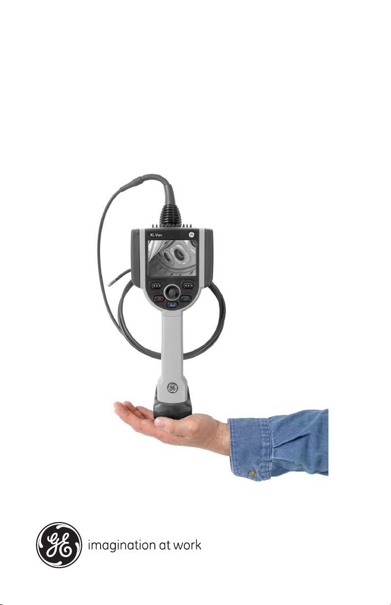
GE
Measurement & Control Remote Visual Inspection
XL Vu+™ VideoProbe®
Operating Manual
XLVUCMAN Rev. A
July 2013
Page 2

Page 3

XL Vu+™ VideoProbe®
Video Borescope
Operating Manual
XLVUCMAN Rev. A
July 2013
ge-mcs.com
©2013 General Electric Company. All rights reserved.
Technical content subject to change without notice.
Page 4

[no content intended for this page]
ii
Page 5

Contents
Chapter 1. Introduction
1.1 About this Manual . . . . . . . . . . . . . . . . . . . . . . . . . . . . . . . . . . . . . . . . . . . . . 1
1.2 Standard XL Vu+ System . . . . . . . . . . . . . . . . . . . . . . . . . . . . . . . . . . . . . . . 1
1.3 Optional Accessories . . . . . . . . . . . . . . . . . . . . . . . . . . . . . . . . . . . . . . . . . . .2
1.4 Optional Software . . . . . . . . . . . . . . . . . . . . . . . . . . . . . . . . . . . . . . . . . . . . .2
1.5 Indicators and Connectors . . . . . . . . . . . . . . . . . . . . . . . . . . . . . . . . . . . . . . .3
1.6 Button Controls . . . . . . . . . . . . . . . . . . . . . . . . . . . . . . . . . . . . . . . . . . . . . . . 5
Chapter 2. Safety Information
2.1 Symbols and Terms . . . . . . . . . . . . . . . . . . . . . . . . . . . . . . . . . . . . . . . . . . . .7
2.2 General Warnings . . . . . . . . . . . . . . . . . . . . . . . . . . . . . . . . . . . . . . . . . . . . . 7
2.3 General Cautions . . . . . . . . . . . . . . . . . . . . . . . . . . . . . . . . . . . . . . . . . . . . . .8
2.4 Battery Warnings . . . . . . . . . . . . . . . . . . . . . . . . . . . . . . . . . . . . . . . . . . . . . .9
2.5 Symboles et termes employés . . . . . . . . . . . . . . . . . . . . . . . . . . . . . . . . . . . 10
2.6 Avertissements généraux . . . . . . . . . . . . . . . . . . . . . . . . . . . . . . . . . . . . . . . 10
2.7 Mentions générales « Attention » . . . . . . . . . . . . . . . . . . . . . . . . . . . . . . . . 11
2.8 Avertissements liés à la batterie. . . . . . . . . . . . . . . . . . . . . . . . . . . . . . . . . . 12
Chapter 3. Getting Started
3.1 System Removal . . . . . . . . . . . . . . . . . . . . . . . . . . . . . . . . . . . . . . . . . . . . . 13
3.2 System Power ON . . . . . . . . . . . . . . . . . . . . . . . . . . . . . . . . . . . . . . . . . . . . 14
3.3 System Power OFF . . . . . . . . . . . . . . . . . . . . . . . . . . . . . . . . . . . . . . . . . . . 14
3.4 System Storage . . . . . . . . . . . . . . . . . . . . . . . . . . . . . . . . . . . . . . . . . . . . . . 15
3.5 Mounting Accessories . . . . . . . . . . . . . . . . . . . . . . . . . . . . . . . . . . . . . . . . . 16
3.6 The Battery . . . . . . . . . . . . . . . . . . . . . . . . . . . . . . . . . . . . . . . . . . . . . . . . . 17
3.6.1 Installing the Battery . . . . . . . . . . . . . . . . . . . . . . . . . . . . . . . . . . . .17
3.6.2 Removing the Battery . . . . . . . . . . . . . . . . . . . . . . . . . . . . . . . . . . . 17
3.7 Battery Charge Level. . . . . . . . . . . . . . . . . . . . . . . . . . . . . . . . . . . . . . . . . . 18
3.8 Charging the Battery . . . . . . . . . . . . . . . . . . . . . . . . . . . . . . . . . . . . . . . . . . 18
3.9 Keyboard Support . . . . . . . . . . . . . . . . . . . . . . . . . . . . . . . . . . . . . . . . . . . .19
3.10 Saving Images and Video . . . . . . . . . . . . . . . . . . . . . . . . . . . . . . . . . . . . . . 20
3.10.1 Still Images . . . . . . . . . . . . . . . . . . . . . . . . . . . . . . . . . . . . . . . . . . .20
3.10.2 Video . . . . . . . . . . . . . . . . . . . . . . . . . . . . . . . . . . . . . . . . . . . . . . . . 20
XL Vu+™ VideoProbe® Operating Manual iii
Page 6

Contents
3.11 Optical Tips. . . . . . . . . . . . . . . . . . . . . . . . . . . . . . . . . . . . . . . . . . . . . . . . . 21
3.11.1 Optical Tip Removal. . . . . . . . . . . . . . . . . . . . . . . . . . . . . . . . . . . . 21
3.11.2 Optical Tip Installation . . . . . . . . . . . . . . . . . . . . . . . . . . . . . . . . . . 21
3.12 Proper Use of the Tip Tool (3.9 mm only) . . . . . . . . . . . . . . . . . . . . . . . . . 22
3.12.1 Removing Optical Tips . . . . . . . . . . . . . . . . . . . . . . . . . . . . . . . . . . 22
3.12.2 Installing Optical Tips. . . . . . . . . . . . . . . . . . . . . . . . . . . . . . . . . . . 22
Chapter 4. Common Tasks
4.1 GO TO Menu. . . . . . . . . . . . . . . . . . . . . . . . . . . . . . . . . . . . . . . . . . . . . . . . 23
4.1.1 GO TO > File Manager. . . . . . . . . . . . . . . . . . . . . . . . . . . . . . . . . . 23
4.1.2 GO TO > Eject Hardware . . . . . . . . . . . . . . . . . . . . . . . . . . . . . . . . 24
4.1.3 GO TO > Zoom Level. . . . . . . . . . . . . . . . . . . . . . . . . . . . . . . . . . . 25
4.1.4 GO TO > Light Output . . . . . . . . . . . . . . . . . . . . . . . . . . . . . . . . . . 26
4.1.5 GO TO > Long Exposure . . . . . . . . . . . . . . . . . . . . . . . . . . . . . . . . 27
4.1.6 GO TO > Inverse + . . . . . . . . . . . . . . . . . . . . . . . . . . . . . . . . . . . . . 29
4.1.7 GO TO > Invert. . . . . . . . . . . . . . . . . . . . . . . . . . . . . . . . . . . . . . . . 30
4.2 Live Main Menu . . . . . . . . . . . . . . . . . . . . . . . . . . . . . . . . . . . . . . . . . . . . . 31
4.2.1 Live Main Menu > Light Output . . . . . . . . . . . . . . . . . . . . . . . . . . 31
4.2.2 Live Main Menu > Image Control . . . . . . . . . . . . . . . . . . . . . . . . . 32
4.2.3 Live Main Menu > Annotation . . . . . . . . . . . . . . . . . . . . . . . . . . . . 41
4.2.4 Live Main Menu > Eject Hardware . . . . . . . . . . . . . . . . . . . . . . . . 48
4.2.5 Live Main Menu > Setup . . . . . . . . . . . . . . . . . . . . . . . . . . . . . . . . 49
Chapter 5. Operation
5.1 Live Main Menu > Setup . . . . . . . . . . . . . . . . . . . . . . . . . . . . . . . . . . . . . . 51
5.1.1 Live Main Menu > Setup > Screen/Display . . . . . . . . . . . . . . . . . . 51
5.1.2 Live Main Menu > Setup > Measurement Setup . . . . . . . . . . . . . . 58
5.1.3 Live Main Menu > Setup > Video Record Setup . . . . . . . . . . . . . . 66
5.1.4 Live Main Menu > Setup > Still Image Setup . . . . . . . . . . . . . . . . 69
5.1.5 Live Main Menu > Setup > Audio Annotation Setup. . . . . . . . . . . 73
5.1.6 Live Main Menu > Setup > Steering. . . . . . . . . . . . . . . . . . . . . . . . 76
5.1.7 Live Main Menu > Setup > Language Setup . . . . . . . . . . . . . . . . . 77
5.1.8 Live Main Menu > Setup > System Tools . . . . . . . . . . . . . . . . . . . 78
5.2 Live Main Menu > File Manager . . . . . . . . . . . . . . . . . . . . . . . . . . . . . . . . 81
iv XL Vu+™ VideoProbe® Operating Manual
Page 7

Contents
5.3 Capturing Images and Video . . . . . . . . . . . . . . . . . . . . . . . . . . . . . . . . . . . .82
5.4 Articulation Home . . . . . . . . . . . . . . . . . . . . . . . . . . . . . . . . . . . . . . . . . . . . 83
5.5 Freeze Frame . . . . . . . . . . . . . . . . . . . . . . . . . . . . . . . . . . . . . . . . . . . . . . . .84
5.6 Freeze Frame Menu. . . . . . . . . . . . . . . . . . . . . . . . . . . . . . . . . . . . . . . . . . .85
5.6.1 Freeze Frame Menu > Annotation. . . . . . . . . . . . . . . . . . . . . . . . . .86
5.7 Still Image Capture and Playback . . . . . . . . . . . . . . . . . . . . . . . . . . . . . . . . 87
5.8 Video Recording and Playback . . . . . . . . . . . . . . . . . . . . . . . . . . . . . . . . . . 87
5.9 File Manager . . . . . . . . . . . . . . . . . . . . . . . . . . . . . . . . . . . . . . . . . . . . . . . .88
5.9.1 Recalling a File . . . . . . . . . . . . . . . . . . . . . . . . . . . . . . . . . . . . . . . . 88
5.9.2 Copying Files or Folders . . . . . . . . . . . . . . . . . . . . . . . . . . . . . . . . . 91
5.9.3 Deleting Files or Folders . . . . . . . . . . . . . . . . . . . . . . . . . . . . . . . . . 92
5.9.4 Creating a Folder. . . . . . . . . . . . . . . . . . . . . . . . . . . . . . . . . . . . . . .93
5.9.5 Renaming Files or Folders . . . . . . . . . . . . . . . . . . . . . . . . . . . . . . .94
Chapter 6. Measurement
6.1 About Measurement. . . . . . . . . . . . . . . . . . . . . . . . . . . . . . . . . . . . . . . . . . . 95
6.2 Measurement File Formats . . . . . . . . . . . . . . . . . . . . . . . . . . . . . . . . . . . . . 95
6.3 Measurement Optical Tips. . . . . . . . . . . . . . . . . . . . . . . . . . . . . . . . . . . . . .95
6.4 General Measurement Procedure. . . . . . . . . . . . . . . . . . . . . . . . . . . . . . . . . 96
6.4.1 Capturing Measurement Images . . . . . . . . . . . . . . . . . . . . . . . . . . .96
6.4.2 Accuracy Index . . . . . . . . . . . . . . . . . . . . . . . . . . . . . . . . . . . . . . . .96
6.4.3 Measurement Types. . . . . . . . . . . . . . . . . . . . . . . . . . . . . . . . . . . . . 97
6.4.4 Measurement Type Selection . . . . . . . . . . . . . . . . . . . . . . . . . . . . . 98
6.5 Stereo Probe Measurement . . . . . . . . . . . . . . . . . . . . . . . . . . . . . . . . . . . . 100
6.5.1 Positioning the Probe Tip for Maximum Accuracy. . . . . . . . . . . . 100
6.5.2 Accuracy Index . . . . . . . . . . . . . . . . . . . . . . . . . . . . . . . . . . . . . . .101
6.5.3 Matching Cursors . . . . . . . . . . . . . . . . . . . . . . . . . . . . . . . . . . . . .102
6.5.4 Taking Stereo Measurements. . . . . . . . . . . . . . . . . . . . . . . . . . . . . 103
6.5.5 Types of Stereo Measurements . . . . . . . . . . . . . . . . . . . . . . . . . . . 105
6.6 Shadow Probe Measurement . . . . . . . . . . . . . . . . . . . . . . . . . . . . . . . . . . . 110
6.6.1 Positioning the Probe Tip for Maximum Accuracy. . . . . . . . . . . . 110
6.6.2 Accuracy Index . . . . . . . . . . . . . . . . . . . . . . . . . . . . . . . . . . . . . . . 110
6.6.3 Taking Shadow Measurements . . . . . . . . . . . . . . . . . . . . . . . . . . . 112
6.6.4 Types of Shadow Measurements. . . . . . . . . . . . . . . . . . . . . . . . . . 113
XL Vu+™ VideoProbe® Operating Manual v
Page 8

Contents
6.7 Comparison Measurement. . . . . . . . . . . . . . . . . . . . . . . . . . . . . . . . . . . . . 120
6.7.1 Positioning the Probe Tip for Maximum Accuracy . . . . . . . . . . . 120
6.7.2 Taking Comparison Measurements. . . . . . . . . . . . . . . . . . . . . . . . 120
6.8 Menu Directed Inspection (MDI) . . . . . . . . . . . . . . . . . . . . . . . . . . . . . . . 121
Chapter 7. Maintenance
7.1 Inspecting and Cleaning the System . . . . . . . . . . . . . . . . . . . . . . . . . . . . . 123
7.1.1 Cleaning Optical Tips . . . . . . . . . . . . . . . . . . . . . . . . . . . . . . . . . . 123
7.2 Troubleshooting Measurements . . . . . . . . . . . . . . . . . . . . . . . . . . . . . . . . 124
7.2.1 Inaccurate Stereo or Shadow Measurements . . . . . . . . . . . . . . . . 124
7.2.2 Inaccurate Stereo Measurements. . . . . . . . . . . . . . . . . . . . . . . . . . 124
7.2.3 Inaccurate Shadow Measurements . . . . . . . . . . . . . . . . . . . . . . . . 125
7.3 Sales and Technical Support . . . . . . . . . . . . . . . . . . . . . . . . . . . . . . . . . . . 125
7.4 Web Site . . . . . . . . . . . . . . . . . . . . . . . . . . . . . . . . . . . . . . . . . . . . . . . . . . 125
7.5 Service. . . . . . . . . . . . . . . . . . . . . . . . . . . . . . . . . . . . . . . . . . . . . . . . . . . . 126
Chapter 8. Technical Specifications
8.1 Operating Temperature . . . . . . . . . . . . . . . . . . . . . . . . . . . . . . . . . . . . . . . 127
8.2 Storage. . . . . . . . . . . . . . . . . . . . . . . . . . . . . . . . . . . . . . . . . . . . . . . . . . . . 127
8.3 Camera . . . . . . . . . . . . . . . . . . . . . . . . . . . . . . . . . . . . . . . . . . . . . . . . . . . 127
8.4 System . . . . . . . . . . . . . . . . . . . . . . . . . . . . . . . . . . . . . . . . . . . . . . . . . . . . 128
8.5 Power. . . . . . . . . . . . . . . . . . . . . . . . . . . . . . . . . . . . . . . . . . . . . . . . . . . . . 128
8.6 Power Supply . . . . . . . . . . . . . . . . . . . . . . . . . . . . . . . . . . . . . . . . . . . . . . 129
8.7 Standards Compliance and Classifications . . . . . . . . . . . . . . . . . . . . . . . . 129
8.8 Software . . . . . . . . . . . . . . . . . . . . . . . . . . . . . . . . . . . . . . . . . . . . . . . . . . 129
8.9 Probe Measurements . . . . . . . . . . . . . . . . . . . . . . . . . . . . . . . . . . . . . . . . . 130
8.10 Tip Articulation. . . . . . . . . . . . . . . . . . . . . . . . . . . . . . . . . . . . . . . . . . . . . 130
Appendix A. Optical Tip Table
A.1 Tip Specifications . . . . . . . . . . . . . . . . . . . . . . . . . . . . . . . . . . . . . . . . . . . 131
Appendix B. Chemical Compatibility
Appendix C. Warranty
Appendix D. Verifying Measurement Tips
D.1 Verification Blocks . . . . . . . . . . . . . . . . . . . . . . . . . . . . . . . . . . . . . . . . . . 137
vi XL Vu+™ VideoProbe® Operating Manual
Page 9

Contents
D.2 Verification Procedure . . . . . . . . . . . . . . . . . . . . . . . . . . . . . . . . . . . . . . . . 137
Appendix E. Environmental Compliance
E.1 Waste Electrical and Electronic Equipment Directive. . . . . . . . . . . . . . . . 139
E.2 Battery Disposal. . . . . . . . . . . . . . . . . . . . . . . . . . . . . . . . . . . . . . . . . . . . . 139
E.2.1 What do the Markings Mean? . . . . . . . . . . . . . . . . . . . . . . . . . . . .140
E.2.2 The Risks and Your Role in Reducing Them . . . . . . . . . . . . . . . . 140
Appendix F. Agency Certifications
F.1 European Equipment Classification . . . . . . . . . . . . . . . . . . . . . . . . . . . . . 141
F.2 Safety Mark . . . . . . . . . . . . . . . . . . . . . . . . . . . . . . . . . . . . . . . . . . . . . . . . 141
F.3 Additional Certification Testing . . . . . . . . . . . . . . . . . . . . . . . . . . . . . . . . 141
F.4 Canadian Notice. . . . . . . . . . . . . . . . . . . . . . . . . . . . . . . . . . . . . . . . . . . . .141
F.5 FCC Compliance . . . . . . . . . . . . . . . . . . . . . . . . . . . . . . . . . . . . . . . . . . . . 142
Appendix G. Creating a Personalized Logo File
G.1 Logo File Requirements . . . . . . . . . . . . . . . . . . . . . . . . . . . . . . . . . . . . . . 143
G.2 Creating the Logo File. . . . . . . . . . . . . . . . . . . . . . . . . . . . . . . . . . . . . . . . 143
Appendix H. Restoring Factory Defaults
XL Vu+™ VideoProbe® Operating Manual vii
Page 10

Contents
[no content intended for this page]
viii XL Vu+™ VideoProbe® Operating Manual
Page 11

Chapter 1. Introduction
Chapter 1. Introduction
1.1 About this Manual
This manual and the related equipment is intended for visual inspection technicians
with a basic understanding of inspection principles and practices, and who are
familiar with basic computer operations, but who may not have experience with a
video borescope system.
The manual contains complete setup, operating, and maintenance instructions for
the XL Vu+ video borescope system. The manual also provides a product overview,
step-by-step procedures, and reference information.
To ensure operator safety, please read and understand this manual prior to using the
system.
For additional assistance, go to www.ge-mcs.com
manual for a complete listing of contact information.
or see the back cover of this
1.2 Standard XL Vu+ System
The standard XL Vu+ package includes the following items:
XL Vu+ Instrument USB Thumb Drive
2-hour Li-Ion Battery Operating Manual
Storage Case Documentation CD-ROM
AC Adapter/Battery Charger Quick-Start Card
Optical Tip Storage Case
XL Vu+™ VideoProbe® Operating Manual 1
Page 12

Chapter 1. Introduction
1.3 Optional Accessories
The following optional accessories are available for the XL Vu+ system:
Spare 4-hour Battery Sun Visor
VGA Video Cable Headset
Insertion Tube Gripper USB Thumb Drive
Insertion Tube Rigidizer Belt Clip
Mini-Magic Arm Keyboard
12 VDC Power Adapter Optical Tips
Handset Holder Measurement Optical Tips
Soft Case Mini-Magic Clamp Kit
Neck Strap Magic Arm Kit
1.4 Optional Software
The following optional software is available for the XL Vu+ system:
Menu Directed Inspection (MDI)
2 XL Vu+™ VideoProbe® Operating Manual
Page 13

Chapter 1. Introduction
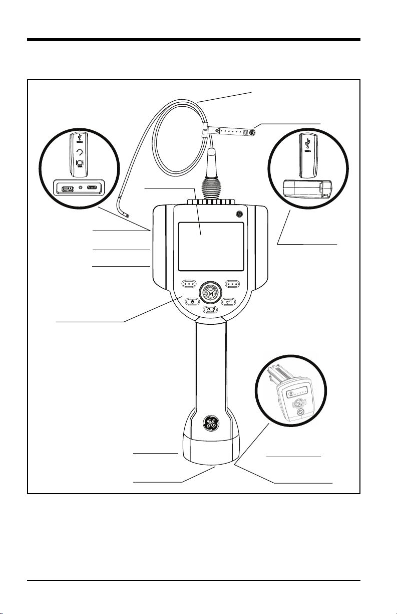
1.5 Indicators and Connectors
The XL Vu+ instrument includes the following indicators and connectors (see
Figure 1 on page 4):
1. LCD Screen
2. USB2 Port
3. Integrated 2.5 mm Headset/Microphone Jack
4. VGA Output
5. Controls
6. 2-hour Lithium Ion Battery
7. Battery Locking Screw
8. Battery Charge Indicator
9. AC Adaptor Input
10. USB1 Bay
11. Insertion Tube Strap
12. Insertion Tube
XL Vu+™ VideoProbe® Operating Manual 3
Page 14
Chapter 1. Introduction
1.5 Indicators and Connectors (cont .)
1
XL Vu+
2
3
4
5
12
11
10
6
7
9
8
Figure 1: XL Vu+ Indicators and Connectors
4 XL Vu+™ VideoProbe® Operating Manual
Page 15
Chapter 1. Introduction
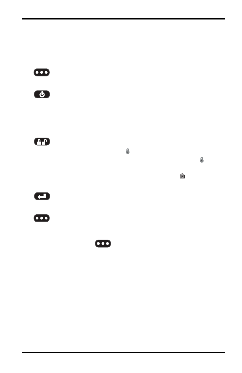
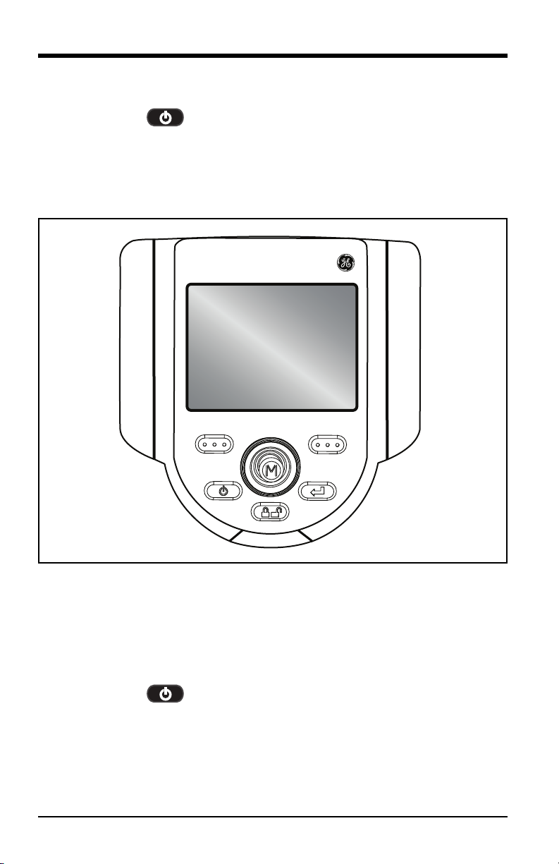
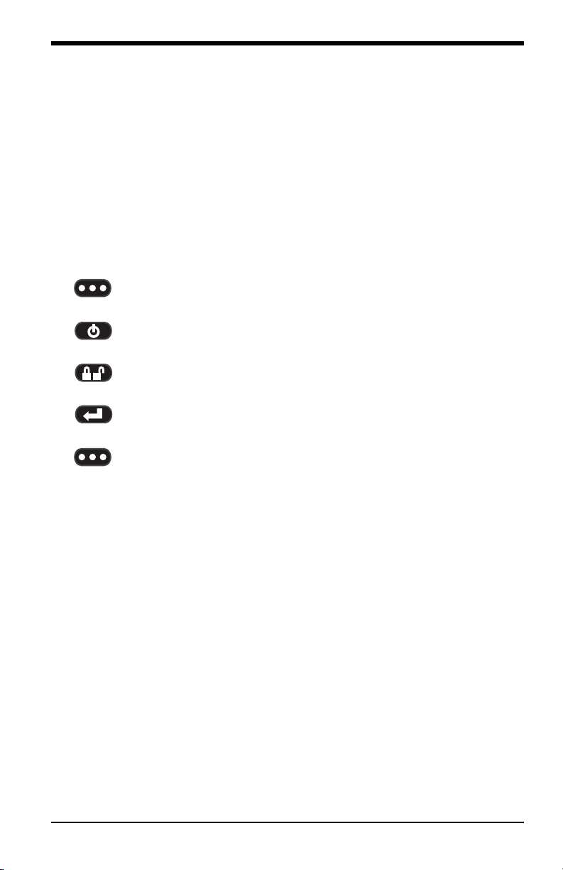
1.6 Button Controls
The buttons listed below and shown in Figure 2 on page 6 control the basic and
advanced operation of the XL Vu+ VideoProbe.
1. Left Soft Key - Activates the screen command listed on the system
LCD. This key most frequently returns the user BACK one screen.
2. Power/Exit Button - Turns the system power ON/OFF. Also used to
exit menus, return to live/frozen video and disable image control features.
3. Joystick - Controls articulation of the probe. Press to activate the Live Main
Menu, Recalled Image Menu, and Freeze Frame Menu. Push the joystick
left/right/up/down to navigate menus and sub-menus.
4. Steering Control - Press and release to keep bending neck locked in
place after the joystick is released. A lock will appear on the LCD when
enabled. Press and release again to unlock the steering control. The lock
will disappear from the LCD when disabled. Also, press and hold to engage the
HOME function to straighten the bending neck. A blinking HOME icon
will appear on the LCD when enabled. This icon will disappear when finished.
5. Freeze/Enter Button - Freezes the image on-screen. Also acts as an
ENTER key for selecting menu options.
6. Right Soft Key - Activates the screen command listed on the system
LCD. This key most frequently serves to SELECT active menu choices. This
key also provides an alternative method to access the LIVE MAIN MENU, by
pressing and holding the right soft key labeled GOTO for about three
seconds.
XL Vu+™ VideoProbe® Operating Manual 5
Page 16
Chapter 1. Introduction
1.6 Button Controls (cont.)
1
2
XL Vu+
6
3
4
5
Figure 2: XL Vu+ Controls
6 XL Vu+™ VideoProbe® Operating Manual
Page 17
Chapter 2. Safety Information
Chapter 2. Safety Information
IMPORTANT: Before using or servicing the XL Vu+ system, read and understand
the following safety information.
2.1 Symbols and Terms
The following symbol appears on the product:
See accompanying documentation.
2.2 General Warnings
The following warning statements apply to general use of the XL Vu+ system.
Warning statements that apply specifically to particular procedures appear in the
corresponding sections of this manual.
Do not allow the conductive insertion tube, system or its working
tools to come in direct contact with any voltage or current source.
Prevent all contact with live electrical conductors or terminals.
Damage to the equipment and/or electrical shock to the operator
may result.
Do not use this system in explosive environments.
USE PROPERLY. Using any piece of this equipment in a
manner not specified by the manufacturer may impair the
product’s ability to protect the user from harm.
XL Vu+™ VideoProbe® Operating Manual 7
Page 18
Chapter 2. Safety Information
2.3 General Cautions
The following caution statements apply to use of the XL Vu+ system in general.
Caution statements that apply specifically to particular procedures appear in the
corresponding sections of this manual.
HANDLE PROBE CAREFULLY. Keep the insertion tube away from sharp
objects that might penetrate its outer sheath. Keep the whole insertion tube as
straight as possible during operation; loops or bends anywhere in the tube decrease
its ability to steer the probe tip. Avoid bending the insertion tube sharply.
IMPORTANT: Always use the Home button to straighten the bending neck before
withdrawing the insertion tube from the inspection area or putting
the probe away. Never pull, twist, or straighten the bending neck by
hand; internal damage may result. At the first sign of damage, return
the probe for repair.
Certain substances may damage the probe. For a list of substances that are safe for
the probe, see “Chemical Compatibility” on page 133.
8 XL Vu+™ VideoProbe® Operating Manual
Page 19
Chapter 2. Safety Information
2.4 Battery Warnings
Only use the battery (XLGOABATTA or XLGOABATTB) and power supply
(XLGOACHGR or XLGOAAUTOC) specified for use with the XL Vu+ system.
Before using the XL Vu+ system, thoroughly review the instructions in this manual
for using the battery and battery charger, Always observe these instructions during
use of the instrument.
WARNING!
• Do not place the battery in fire or exceed the battery operating temperature.
• Do not pierce the battery with nails, strike the battery with a hammer, step on
the battery, or otherwise subject it to strong impacts or shocks.
• Do not expose the battery to water or salt water, or allow the battery to get wet.
• Do not disassemble or modify the battery.
Battery Communication Error: If the XL Vu+ shows this error message on the
display, please contact your nearest customer support center.
Using the battery outside its recommended operating range will result in
degradation of the performance and service life. When storing the battery, be sure
to remove it from the base unit.
The recommended temperature range for Li-Ion battery operation is:
Discharge (when using the instrument): -20 to +46°C
Recharging: 0 to 40°C
Storage: -25 to +60°C
XL Vu+™ VideoProbe® Operating Manual 9
Page 20
Chapter 2. Safety Information
IMPORTANT : avant l’utilisation ou l’entretien du système, vous devez lire et
comprendre les informations de sécurité qui suivent.
2.5 Symboles et termes employés
Les symboles suivants sont apposés sur le produit :
Voir la documentation jointe.
2.6 Avertissements généraux
Les avertissements suivants s’appliquent à l’utilisation du système en général. Les
avertissements qui s’appliquent spécifiquement à des procédures particulières sont
indiqués dans les sections correspondantes de ce manuel.
Le système XL Vu+ et les outils de travail qui l’accompagnent ne
doivent jamais entrer en contact direct avec une source de tension
ou de courant. Évitez tout contact avec des conducteurs ou des
bornes électriques sous tension. L’équipement risquerait d’être
endommagé, ou l’opérateur de subir un choc électrique.
N’utilisez pas ce système dans un environnement à risque
d’explosion.
UTILISER CORRECTEMENT. Si un élément de cet
équipement est utilisé d’une manière non indiquée par le
fabricant, l’utilisateur peut ne plus être protégé des risques
de blessure.
10 XL Vu+™ VideoProbe® Operating Manual
Page 21
Chapter 2. Safety Information
2.7 Mentions générales «Attention»
Les mentions « Attention » qui suivent s’appliquent à l’utilisation de l’appareil
XL Go en général. Les mentions « Attention » qui s’appliquent spécifiquement à
des procédures particulières sont indiquées dans les sections correspondantes du
manuel.
MANIPULER LA SONDE AVEC PRÉCAUTION. Maintenez la gaine de la
sonde à l’écart d’objets pointus ou tranchants qui risqueraient de traverser son
fourreau. Maintenez toute la gaine aussi droite que possible pendant l’utilisation :
en cas de boucle ou de courbure, il est plus difficile de piloter le bout de la sonde.
Évitez de trop courber la gaine.
IMPORTANT : utilisez toujours le bouton de rangement pour redresser le
béquillage avant de rétracter la gaine de la zone d’inspection ou
de ranger la sonde. Ne manipulez jamais le béquillage à la main
pour le tirer, le courber ou le redresser : vous risqueriez de
l’endommager à l’intérieur. Envoyez la sonde en réparation au
premier signe d’endommagement.
Certaines substances risquent d’endommager la sonde. Pour consulter la liste des
substances sans danger pour la sonde, voir “Chemical Compatibility” on page 133.
XL Vu+™ VideoProbe® Operating Manual 11
Page 22
Chapter 2. Safety Information
2.8 Avertissements liés à la batterie
Utilisez uniquement la batterie (XLGOABATTA or XLGOABATTB) et
l’alimentation (XLGOACHGR or XLGOAAUTOC) spécifiées pour être utilisées
avec le système XL Vu+.
Avant utilisation, lisez attentivement les instructions contenues dans ce manuel
relatives à la batterie et au chargeur de batterie pour bien les comprendre, et
respectez ces instructions pendant l’utilisation de l’appareil.
AVERTISSEMENT!
• Ne jetez pas la batterie au feu et ne dépassez pas sa température de
fonctionnement.
• Ne percez pas la batterie avec des clous, ne la frappez pas avec un marteau, ne
marchez pas dessus et ne la soumettez pas à des impacts ou des chocs violents.
• N’exposez pas la batterie à l’eau douce ou salée, et évitez de la mouiller.
• Ne désassemblez pas la batterie et ne la modifiez pas.
Erreur de communication de la batterie. Veuillez contacter le Service clientèle
au numéro +1 315 554 2000.
L’utilisation de la batterie en dehors de la plage de fonctionnement recommandée
entraînerait une dégradation de ses performances et de sa longévité. Lorsque vous
stockez la batterie, veillez à la retirer de sa base.
Plage de température recommandée pour le fonctionnement de la batterie
Lithium-Ion :
Décharge (à l’utilisation de l’appareil) : -20 à +46°C
Recharge : 0 à +40°C
Stockage : -25 à +60°C
12 XL Vu+™ VideoProbe® Operating Manual
Page 23
Chapter 3. Getting Started
Chapter 3. Getting Started
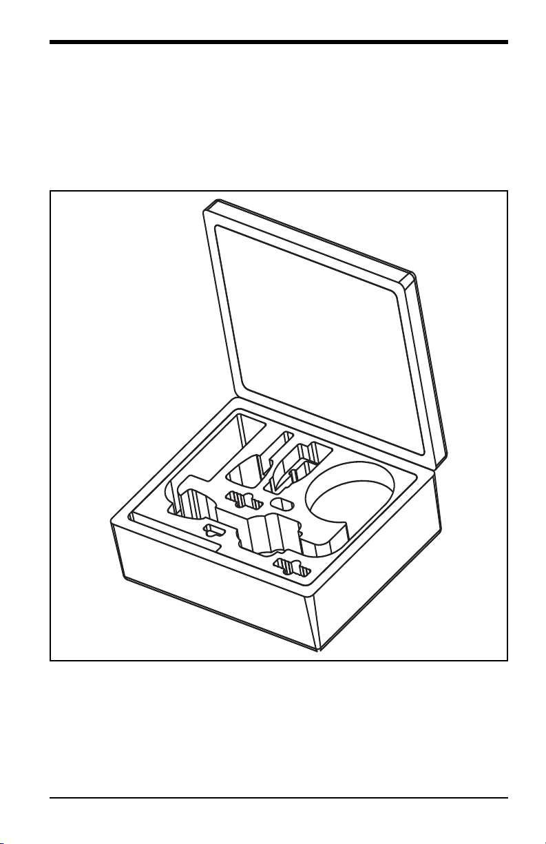
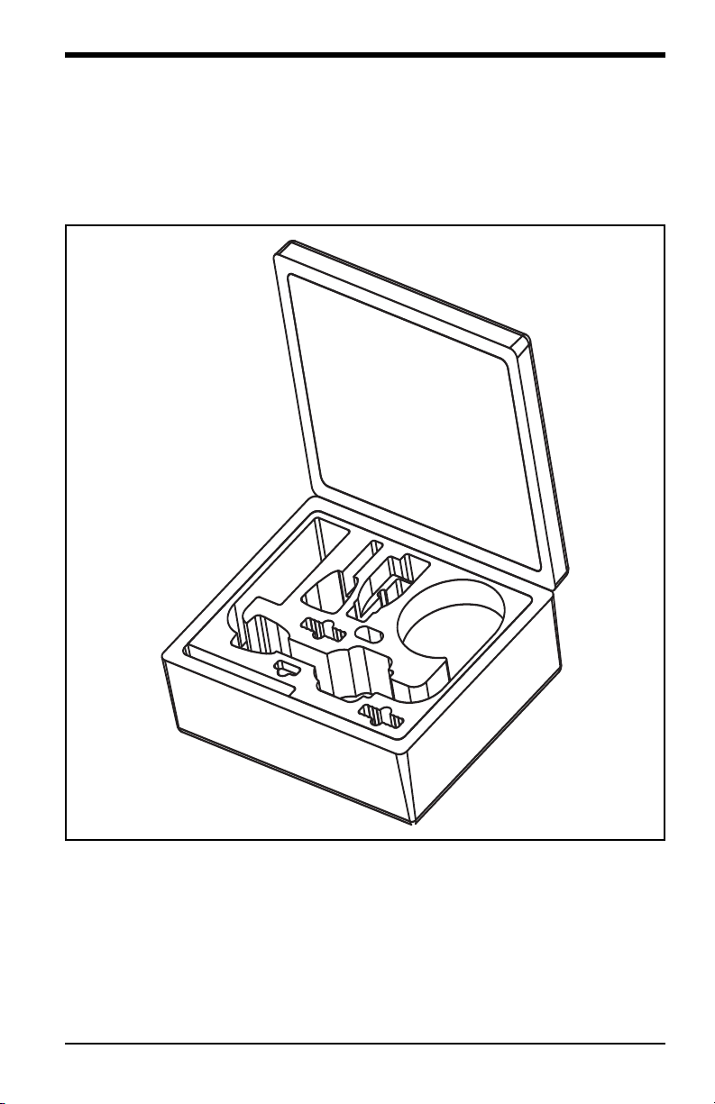
3.1 System Removal
Gently remove the insertion tube from the internal storage reel and lift the handset
from the storage case (see Figure 3 below).
Figure 3: Removing the XL Vu+ from the Case
XL Vu+™ VideoProbe® Operating Manual 13
Page 24
Chapter 3. Getting Started
3.2 System Power ON
Press and hold the Power/Exit key briefly to power the system ON. The
buttons and Liquid Crystal Display (LCD) will light up and begin the power-up
sequence (see Figure 4 below). After approximately 30 seconds, select the desired
language. The system screen will display live video and screen prompts, and is now
ready for use.
XL Vu+
RECORD GOTO
Figure 4: Powering the XL Vu+ ON
Note: All batteries are shipped with only a partial charge. The batteries should be
fully charged prior to use.
3.3 System Power OFF
Press and hold the Power/Exit key until the “SYSTEM SHUTTING
DOWN” message appears. Illumination of the buttons and the LCD will be
terminated when the system is completely powered down.
14 XL Vu+™ VideoProbe® Operating Manual
Page 25
Chapter 3. Getting Started
3.4 System Storage
Place the tip of the insertion tube into the orange funnel and gently feed it into the
storage reel (see Figure 5 below). Place the XL Vu+ handset into the designated
foam cutout, with the LCD screen facing up.
Figure 5: Storing the XL Vu+ in the Case
XL Vu+™ VideoProbe® Operating Manual 15
Page 26
Chapter 3. Getting Started
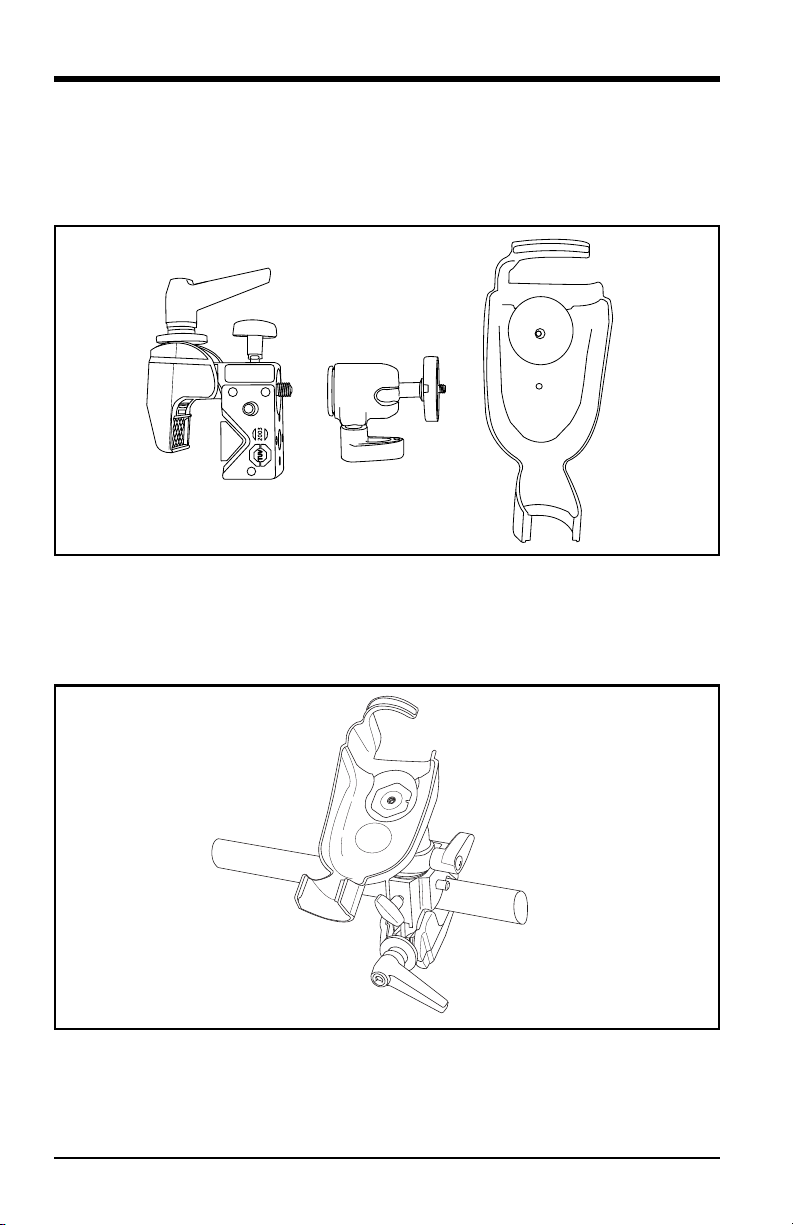
3.5 Mounting Accessories
Assemble the optional mounting accessories, as shown in Figure 6 below, by
screwing together the mini magic clamp, swivel ball, and handset holder.
Figure 6: Assembling the Mounting Accessories
Secure the XL Vu+ mini magic clamp, as shown in Figure 7 below, and place the
XL Go system in the handset holder.
Figure 7: Securing the Mounting Assembly
16 XL Vu+™ VideoProbe® Operating Manual
Page 27
Chapter 3. Getting Started
XL Vu+
3.6 The Battery
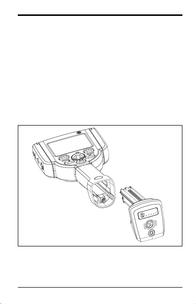
3.6.1 Installing the Battery
Insert the battery into the handset (see Figure 8 below). The battery is installed
properly only after the latching mechanism is engaged.
Note: Do not force the battery into the handset, as damage may occur. The battery
is keyed and can only be installed in the proper orientation.
3.6.2 Removing the Battery
Using a slotted screw driver or coin, turn the locking screw counterclockwise and
release the battery (see Figure 8 below).
Note: Do not remove battery while the system is operating.
Figure 8: Removing/Installing the Battery
XL Vu+™ VideoProbe® Operating Manual 17
Page 28
Chapter 3. Getting Started
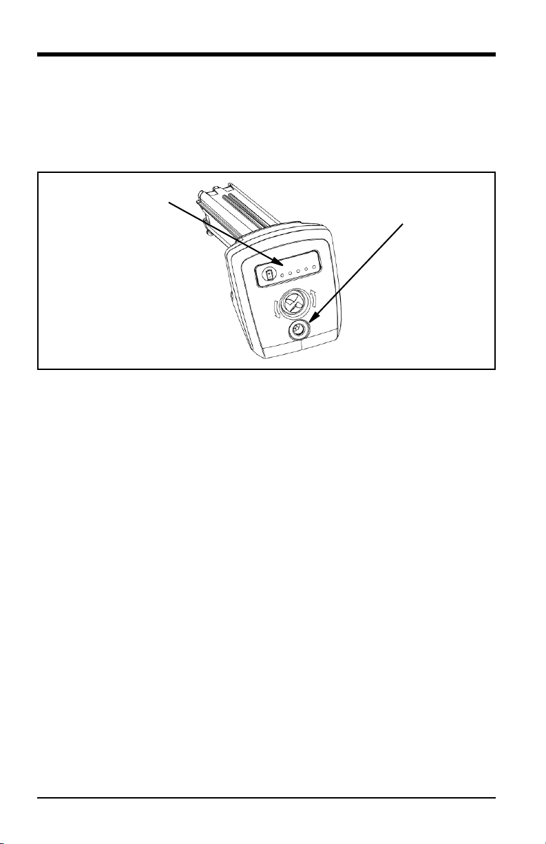
Charge Indicator LED’s
DC Battery Charging Jack
3.7 Battery Charge Level
Check the battery charge by pressing the battery symbol on the front of the battery
(see Figure 9 below). Each indicator light represents approximately 20% of the
battery charge capacity.
Figure 9: Checking the Battery Charge
3.8 Charging the Battery
Note: Battery run time approximately equals the battery charge time. Thus, a
four-hour battery will take approximately four hours to charge.
Plug the included AC-to-DC power adaptor into a suitable AC power source and
connect the DC output of the battery charger into the XL Vu+ battery (see Figure 9
above). The LED battery lights will illuminate according to the amount of charge
attained. The system may be operated while charging, but the battery may also be
charged while disconnected from the system.
Note: When the battery is fully charged, the LED battery lights will turn OFF.
18 XL Vu+™ VideoProbe® Operating Manual
Page 29
Chapter 3. Getting Started
3.9 Keyboard Support
To use an external, USB keyboard, plug the approved device into one of the two
XL Go USB ports.
For a list of approved keyboards, contact your sales representative or customer
support.
The function keys on the keyboard act like the keys on the XL Vu+:
F1: Menu Function on Joystick
F2: Left Soft Key
F3: Power/Exit Button
F4: Steering Control
F5: Enter Key
F6: Right Soft Key
Note: External keyboards support only the top level functions and will not support
the press-and-hold functions, such as video recording.
XL Vu+™ VideoProbe® Operating Manual 19
Page 30
Chapter 3. Getting Started
3.10 Saving Images and Video
3.10.1 Still Images
To capture a still image, compose the picture and press and release
Freeze/Enter. Press the right soft key, labeled SAVE on the LCD above, to
save to the default location.
Alternately, from live video, press and hold Freeze/Enter to quick-save.
3.10.2 Video
To record live video, press and hold the left soft key, labeled RECORD on
the LCD above. A red RECORD symbol will appear in the upper right hand corner
of the screen. When the video is stopped, it will automatically save to the default
location.
Note: See “Capturing Measurement Images” on page 96 for instructions on saving
images for future re-measurement on the XL Vu+ or on a PC.
20 XL Vu+™ VideoProbe® Operating Manual
Page 31

Chapter 3. Getting Started
3.11 Optical Tips
Optical tips are attached to the insertion tube using a double thread. This prevents
the unintended loss of optical tips from the probe. Each optical tip provides a
unique depth of field (DOF), field of view (FOV) and direction of view (DOV). A
complete list of available tips is provided in “Optical Tip Table” on page 131.
3.11.1 Optical Tip Removal
To remove an optical tip (see Figure 10 below), complete the following steps:
1. Grasp the head of the probe with one hand and gently loosen the tip
counterclockwise with the other hand. The tip has cleared the first set of
threads when it spins freely.
2. Gently pull the tip away from the probe and continue loosening
counterclockwise until the tip has cleared the second set of threads.
Figure 10: Removing An Optical Tip
3.11.2 Optical Tip Installation
To install an optical tip, complete the following steps:
1. Ensure that the optical tip is clean. If necessary, clean the tip as described in
“Cleaning Optical Tips” on page 123.
2. Grasp the head of the probe with one hand and gently turn the tip clockwise
with the other hand. The tip has cleared the first set of threads when it spins
freely and then seats when gentle force applied.
3. Gently push the tip toward the probe and continue turning clockwise on the
second set of threads until the tip is attached finger tight. Do not over-tighten
the tip. Pull gently on the tip to verify proper attachment to the probe.
Note: Never use tools or excessive force to install or remove an optical tip.
XL Vu+™ VideoProbe® Operating Manual 21
Page 32

Chapter 3. Getting Started
3.12 Proper Use of the Tip Tool (3.9 mm only)
3.12.1 Removing Optical Tips
To remove an optical tip, complete the following steps:
1. Apply the empty tip tool to the probe head.
2. Apply pressure while turning the tool counterclockwise.
3. When the tip tool spins freely, gently pull up while twisting counterclockwise
to release the second set of threads.
4. Remove the tip tool and the captured tip.
3.12.2 Installing Optical Tips
To install an optical tip, complete the following steps:
1. Apply the tip tool containing the desired optical tip to the probe head.
2. Apply pressure on the tool while turning it clockwise.
3. When the tip tool spins freely, gently push down while twisting the tool
clockwise to engage the second set of threads.
4. Pull gently on the tip tool to verify proper attachment of the tip to the probe
head.
5. Remove the tip tool.
IMPORTANT: Never use excessive force to install or remove an optical tip.
22 XL Vu+™ VideoProbe® Operating Manual
Page 33

Chapter 4. Common Tasks
Chapter 4. Common Tasks
4.1 GO TO Menu
Many common operating tasks are available in the GO TO menu. This menu is
available by pressing the right soft key, labeled GO TO on the LCD above,
during live video mode. To exit any menu, press Power/Exit.
4.1.1 GO TO > File Manager
To enter the file manager menu (see Figure 11 below), navigate to
FILE MANAGER with the joystick and press the right soft key, labeled
SELECT on the LCD above.
XL Vu+
GO TO MENU
FILE MANAGER
EJECT HARDWARE
ZOOM LEVEL
LIGHT OUTPUT
LONG EXPOSURE
INVERSE +
INVERT
BACK SELECT
Figure 11: The GO TO > File Manager Menu
XL Vu+™ VideoProbe® Operating Manual 23
Page 34

Chapter 4. Common Tasks
4.1.2 GO TO > Eject Hardware
To eject a USB thumb drive before removal, use the joystick to navigate to the right
of the EJECT HARDWARE option (see Figure 12 below). To eject the desired
drive, press the right soft key, labeled SELECT on the LCD above.
Note: Always use EJECT HARDWARE before removing a USB thumb drive, to
prevent loss of data.
XL Vu+
GO TO MENU
FILE MANAGER
EJECT HARDWARE
ZOOM LEVEL
LIGHT OUTPUT
LONG EXPOSURE
INVERSE +
INVERT
BACK SELECT
USB1
USB2
Figure 12: The GO TO > Eject Hardware Menu
24 XL Vu+™ VideoProbe® Operating Manual
Page 35

Chapter 4. Common Tasks
1 5
4.1.3 GO TO > Zoom Level
Zoom levels from 1 (normal view) to 5 (5X normal view) are available. Navigate to
the right of the ZOOM LEVEL option (see Figure 13 below), and use the joystick
to adjust the zoom level.
XL Vu+
GO TO MENU
FILE MANAGER
EJECT HARDWARE
ZOOM LEVEL
LIGHT OUTPUT
LONG EXPOSURE
INVERSE +
INVERT
BACK SELECT
Figure 13: The GO TO > Zoom Level Menu
XL Vu+™ VideoProbe® Operating Manual 25
Page 36

Chapter 4. Common Tasks
4.1.4 GO TO > Light Output
To turn the LED optical light ON or OFF, navigate to the right of the
LIGHT OUTPUT option, and select either ON or OFF.
XL Vu+
GO TO MENU
FILE MANAGER
EJECT HARDWARE
ZOOM LEVEL
LIGHT OUTPUT
LONG EXPO SURE
INVERSE +
INVERT
BACK SELECT
ON
OFF
Figure 14: The GO TO > Light Output Menu
Note: Pressing the Freeze Frame key is a convenient way to temporarily
turn off the light output and is ideal for changing optical tips and conserving
battery charge.
26 XL Vu+™ VideoProbe® Operating Manual
Page 37

Chapter 4. Common Tasks
4.1.5 GO TO > Long Exposure
The XL Vu+ system can brighten the image by varying the exposure time. Keep the
probe tip as still as possible when capturing an image with a long exposure, to
minimize the risk of blurring.
Navigate to the LONG EXPOSURE option (see Figure 15 below) to choose
manual exposure, automatic long exposure, or to turn long exposure off. Long
Exposure may be turned off in live video mode by pressing the Power/Exit
button.
XL Vu+
GO TO MENU
FILE MANAGER
EJECT HARDWARE
ZOOM LEVEL
LIGHT OUTPUT
LONG EXPOSURE
INVERSE +
INVERT
BACK SELECT
Figure 15: The GO TO > Long Exposure Menu
XL Vu+™ VideoProbe® Operating Manual 27
Page 38

Chapter 4. Common Tasks
4.1.5 GO TO > Long Exposure (cont.)
After selecting LONG EXPOSURE (see Figure 16 below), the following options
are available: MANUAL, AUTO and OFF.
XL Vu+
LONG EXPOSURE
MANUAL
AUTO
X OFF
BACK SELECT
Figure 16: The GO TO > Long Exposure Options
28 XL Vu+™ VideoProbe® Operating Manual
Page 39

Chapter 4. Common Tasks
4.1.6 GO TO > Inverse +
The INVERSE + option reverses the brightness of the image, similar to a
photographic negative. This enhances the image contrast, making subtle details
more visible. To activate or deactivate this function, navigate to The INVERSE +
option (see Figure 17 below), and choose either ON or OFF. INVERSE + may be
turned OFF in live video mode by pressing the Power/Exit button.
XL Vu+
GO TO MENU
FILE MANAGER
EJECT HARDWARE
ZOOM LEVEL
LIGHT OUTPUT
LONG EXPOSURE
INVERSE +
INVERT
BACK SELECT
ON
OFF
Figure 17: The GO TO > Inverse + Menu
XL Vu+™ VideoProbe® Operating Manual 29
Page 40

Chapter 4. Common Tasks
4.1.7 GO TO > Invert
The INVERT function flips an image horizontally. To activate or deactivate this
function, navigate to the INVERT option (see Figure 18 below), and choose either
ON or OFF. INVERT may be turned OFF in live video mode by pressing the
Power/Exit button.
XL Vu+
GO TO MENU
FILE MANAGER
EJECT HARDWARE
ZOOM LEVEL
LIGHT OUTPUT
LONG EXPOSURE
INVERSE +
INVERT
BACK SELECT
ON
OFF
Figure 18: The GO TO > Invert Menu
Note: INVERT is typically used while a side view tip is installed in order to
compensate for the inversion caused by this type of tip.
30 XL Vu+™ VideoProbe® Operating Manual
Page 41

Chapter 4. Common Tasks
4.2 Live Main Menu
To activate the LIVE MAIN MENU, press and release the joystick. To exit any
submenu, press the Power/Exit button. An alternative method for accessing
the LIVE MAIN MENU is to press and hold the right soft key, labeled
GO TO on the LCD above, for about three seconds.
4.2.1 Live Main Menu > Light Output
To turn the LED optical light ON or OFF, use the joystick to navigate to the
LIGHT OUTPUT option (see Figure 19 below), and select either ON or OFF.
XL Vu+
LIVE MAIN MENU
LIGHT OUTPUT
IMAGE CONTROL
ANNOTATION
EJECT HARDWARE
SETUP
FILE MANAGER
BACK SELECT
ON
OFF
Figure 19: The Live Main Menu > Light Output Menu
Note: Pressing the Freeze Frame key is a convenient way to temporarily
turn off the light output and is ideal for changing optical tips and conserving
battery charge.
XL Vu+™ VideoProbe® Operating Manual 31
Page 42

Chapter 4. Common Tasks
4.2.2 Live Main Menu > Image Control
From the LIVE MAIN MENU, select the IMAGE CONTROL option (see
Figure 20 below). Any changes made to the Image Controls take effect
immediately.
XL Vu+
LIVE MAIN MENU
LIGHT OUTPUT
IMAGE CONTROL
ANNOTATION
EJECT HARDWARE
SETUP
FILE MANAGER
BACK SELECT
Figure 20: The Live Main Menu > Image Control Menu
The following Image Control options are available:
• Image Brightness (see page 33) • Single View (see page 38)
• Zoom Level (see page 34) • Inverse + (see page 39)
• Long Exposure (see page 35) • Invert (see page 40)
• Split Screen (see page 37)
Note: By pressing the Power/Exit button twice, any image control features
will be turned OFF and returned to the factory default settings.
32 XL Vu+™ VideoProbe® Operating Manual
Page 43

Chapter 4. Common Tasks
4.2.2a Live Main Menu > Image Control > Image Brightness
Navigate to IMAGE BRIGHTNESS from the IMAGE CONTROL Menu (see
Figure 21 below), and use the joystick to adjust the image brightness.
XL Vu+
IMAGE CONTROL
IMAGE BRIGHTNESS
ZOOM LEVEL
LONG EXPOSURE
SPLIT SCREEN
SINGLE VIEW
INVERSE +
INVERT
BACK SELECT
0 100
Figure 21: Live Main Menu > Image Control > Image Brightness
XL Vu+™ VideoProbe® Operating Manual 33
Page 44

Chapter 4. Common Tasks
4.2.2b Live Main Menu > Image Control > Zoom Level
Navigate to ZOOM LEVEL from the IMAGE CONTROL Menu (see Figure 22
below), and use the joystick to adjust the zoom level. Digital zoom levels from 1x
to 5x may be selected.
XL Vu+
IMAGE CONTROL
IMAGE BRIGHTNESS
ZOOM LEVEL
LONG EXPO SURE
SPLIT SCREEN
SINGLE VIEW
INVERSE +
INVERT
BACK SELECT
15
Figure 22: Live Main Menu > Image Control > Zoom Level
34 XL Vu+™ VideoProbe® Operating Manual
Page 45

Chapter 4. Common Tasks
4.2.2c Live Main Menu > Image Control > Long Exposure
The XL Vu+ system can brighten the image by varying the exposure time. Keep the
probe tip as still as possible when capturing an image with a long exposure, to
minimize the risk of blurring.
Navigate to the LONG EXPOSURE option (see Figure 23 below) to choose
manual exposure, automatic long exposure, or to turn long exposure off. Long
Exposure may be turned off in live video mode by pressing the Power/Exit
button.
XL Vu+
IMAGE CONTROL
IMAGE BRIGHTNESS
ZOOM LEVEL
LONG EXPOSURE
SPLIT SCREEN
SINGLE VIEW
INVERSE +
INVERT
BACK SELECT
Figure 23: Live Main Menu > Image Control > Long Exposure
XL Vu+™ VideoProbe® Operating Manual 35
Page 46

Chapter 4. Common Tasks
4.2.2c Live Main Menu > Image Control > Long Exposure (cont.)
After selecting LONG EXPOSURE (see Figure 24 below), the following options
are available: MANUAL, AUTO and OFF.
XL Vu+
LONG EXPOSURE
MANUAL
AUTO
X OFF
BACK SELECT
Figure 24: The Live Main Menu > Image Control > Long Exposure Options
36 XL Vu+™ VideoProbe® Operating Manual
Page 47

Chapter 4. Common Tasks
4.2.2d Live Main Menu > Image Control > Split Screen
From a live, frozen, or recalled image, press the joystick to access the LIVE MAIN
MENU > FREEZE FRAME Menu or the LIVE MAIN MENU > RECALLED
IMAGE Menu. Navigate to the SPLIT SCREEN option (see Figure 25 below),
and press the right soft key to SELECT. Choose the area of the screen to
view by moving the joystick left or right and using the right soft key to
SELECT. The left image is frozen and the right image is live.
XL Vu+
IMAGE CONTROL
IMAGE BRIGHTNESS
ZOOM LEVEL
LONG EXPOSURE
SPLIT SCREEN
SINGLE VIEW
INVERSE +
INVERT
BACK SELECT
Figure 25: Live Main Menu > Image Control > Split Screen
XL Vu+™ VideoProbe® Operating Manual 37
Page 48

Chapter 4. Common Tasks
BACK SELECT
IMAGE CONTROL
IMAGE BRIGHTNESS
ZOOM LEVEL
LONG EXPO SURE
SPLIT SCREEN
SINGLE VIEW
INVERSE +
INVERT
ON
OFF
XL Vu+
4.2.2e Live Main Menu > Image Control > Single View
While using a stereo tip, SINGLE VIEW temporarily eliminates the second image.
To access this feature, navigate to SINGLE VIEW from the IMAGE CONTROL
Menu (see Figure 26 and Figure 27 below), and select ON or OFF. Pressing the
Power/Exit button from live video disables SINGLE VIEW.
Figure 26: Live Main Menu > Image Control > Single View
Figure 27: Sample Single View Image
38 XL Vu+™ VideoProbe® Operating Manual
Page 49

Chapter 4. Common Tasks
4.2.2f Live Main Menu > Image Control > Inverse +
The INVERSE + option reverses the brightness of the image, similar to a
photographic negative. This enhances the image contrast, making subtle details
more visible. To activate or deactivate this function, navigate to The INVERSE +
option (see Figure 28 below), and choose either ON or OFF.
XL Vu+
IMAGE CONTROL
IMAGE BRIGHTNESS
ZOOM LEVEL
LONG EXPOSURE
SPLIT SCREEN
SINGLE VIEW
INVERSE +
INVERT
BACK SELECT
ON
OFF
Figure 28: Live Main Menu > Image Control > Inverse +
XL Vu+™ VideoProbe® Operating Manual 39
Page 50

Chapter 4. Common Tasks
4.2.2g Live Main Menu > Image Control > Invert
The INVERT function flips an image horizontally. To activate or deactivate this
function, navigate to the INVERT option (see Figure 29 below), and choose either
ON or OFF.
XL Vu+
IMAGE CONTROL
IMAGE BRIGHTNESS
ZOOM LEVEL
LONG EXPOSURE
SPLIT SCREEN
SINGLE VIEW
INVERSE +
INVERT
BACK SELECT
ON
OFF
Figure 29: Live Main Menu > Image Control > Invert
Note: INVERT is typically used while a side view tip is installed in order to
compensate for the inversion caused by this type of tip.
40 XL Vu+™ VideoProbe® Operating Manual
Page 51

Chapter 4. Common Tasks
4.2.3 Live Main Menu > Annotation
Annotating an XL Vu+ image means adding text or arrows to describe or point out
areas of interest such as cracks, defects, etc. Annotation may be used on live,
frozen, and recalled images.
Note: See the FREEZE FRAME Menu to enable Audio Annotation.
To program the annotation settings, press the joystick to activate the LIVE MAIN
MENU, and select the ANNOTATION option (see Figure 30 below).
XL Vu+
LIVE MAIN MENU
LIGHT OUTPUT
IMAGE CONTROL
ANNOTATION
EJECT HARDWARE
SETUP
FILE MANAGER
BACK SELECT
Figure 30: The Live Main Menu > Annotation Menu
Note: A maximum of 3 lines of text/arrows are allowed per annotation.
The following Annotation options are available:
• Arrow (see page 43) • Hide Annotation (see page 46)
• Preset (see page 44) • Text (see page 47)
• Loading a Preset (see page 45)
XL Vu+™ VideoProbe® Operating Manual 41
Page 52

Chapter 4. Common Tasks
4.2.3 Live Main Menu > Annotation (cont.)
4.2.3a Asian Input Method Editors
The XL Vu+ supports text entry with advanced input methods for Simplified
Chinese (Pinyin) and Japanese (Hiragana to Katakana/Kanji). To utilize these input
methods, the user must have an external keyboard connected to the VideoProbe.
These input methods are active by default when either Chinese or Japanese are
selected as the system language. To return to an on-screen keyboard that does not
utilize these input methods, toggle the “Input Method -/O” button.
Chinese:
The XL Vu+ supports the Pinyin text entry method. For each word or phrase that
you wish to enter, complete the following steps:
1. Using the external keyboard, type the Pinyin representation of the character to
be entered.
2. Use the numbers on the external keyboard to select the desired character from
the candidate list.
3. Press the ENTER key to confirm the selection.
Japanese:
The XL Vu+ supports a text entry method that converts Hiragana to Katakana and
Kanji characters. For each word or phrase you wish to enter, complete the
following steps:
Note: A maximum of 6 Hiragana may be entered for each word or phrase during
Japanese text entry.
1. Using the external keyboard, enter the Hiragana that make up the word being
entered.
2. When all of the Hiragana that make up the word is entered, press the SPACE
BAR on the external keyboard to get a candidate list of characters.
3. Use the numbers on the keyboard to select the desired word.
4. Press the ENTER key to confirm selection.
Note: If the desired word is not shown in the candidate list, press
Page Up/Page Down on the keyboard to cycle through more options.
42 XL Vu+™ VideoProbe® Operating Manual
Page 53

Chapter 4. Common Tasks
4.2.3b Live Main Menu > Annotation > Arrow
To add, edit or clear arrows on a specific image, select ARROW from the
ANNOTATION menu (see Figure 31 below).
XL Vu+
ANNOTATION
TEXT
ARROW
PRESET
HIDE ANNOTATION
BACK SELECT
ADD
EDIT
CLEAR
Figure 31: Live Main Menu > Annotation > Arrow
Note: The maximum number of arrow annotations is 25.
XL Vu+™ VideoProbe® Operating Manual 43
Page 54

Chapter 4. Common Tasks
4.2.3c Live Main Menu > Annotation > Preset
To create, recall or delete a preset annotation that displays throughout an inspection
or to load or export a file containing presets, choose PRESET from the
ANNOTATION menu (see Figure 32 below).
XL Vu+
ANNOTATION
TEXT
ARROW
PRESET
HIDE ANNOTATION
BACK SELECT
CREATE
RECALL
EDIT
DELETE
LOAD
EXPORT
Figure 32: Live Main Menu > Annotation > Preset
Note:
• The maximum number of preset annotations is 100.
• Preset files must be line-delimited .txt files.
• The maximum preset annotation length is calculated by character width
(approximately 28 characters).
44 XL Vu+™ VideoProbe® Operating Manual
Page 55

Chapter 4. Common Tasks
4.2.3d Live Main Menu > Annotation > Loading a Preset
To load a file containing multiple presets onto the XL Vu+, a file may be created on
a PC. This file must conform to the following specifications:
• Line-delimited (each preset must be on a separate line)
• File Type - .txt
• Encoding - UTF8
• Recommended Program - Microsoft™ Notepad
When saving the document, select .txt as the file type and UTF-8 as the encoding,
as shown in the example in Figure 33 below.
Figure 33: Saving a Preset File
To load the Preset File, complete the following steps:
1. Save the Preset.txt file onto external media (CF Card, USB Thumb Drive, etc).
2. Insert the external media into the XL Vu+.
3. Access the LIVE MAIN MENU by pressing the joystick.
4. Navigate to ANNOTATION, and then select PRESET > LOAD.
5. Locate and specify the file that you have created.
XL Vu+™ VideoProbe® Operating Manual 45
Page 56

Chapter 4. Common Tasks
4.2.3e Live Main Menu > Annotation > Hide Annotation
To hide or unhide (i.e., display) an annotation, select HIDE ANNOTATION from
the ANNOTATION menu (see Figure 34 below), and SELECT either ON or OFF.
XL Vu+
ANNOTATION
TEXT
ARROW
PRESET
HIDE ANNOTATION
BACK SELECT
ON
OFF
Figure 34: Live Main Menu > Annotation > Hide Annotation
46 XL Vu+™ VideoProbe® Operating Manual
Page 57

Chapter 4. Common Tasks
4.2.3f Live Main Menu > Annotation > Text
To add, edit, or clear text on a specific image, navigate to the ANNOTATION
menu, and SELECT the TEXT option (see Figure 35 below). A maximum of 50
characters per annotation may be added at the screen shown in Figure 36 below.
XL Vu+
ANNOTATION
TEXT
ARROW
PRESET
HIDE ANNOTATION
BACK SELECT
ADD
EDIT
CLEAR
Figure 35: Live Main Menu > Annotation > Text
XL Vu+
USE JOYSTICK/ENTER TO ENTER TEXT.
^ < > v ENTER SPACE BACKSPACE
B
C
D
E
F
G
H
I
J
K
L
A
O
P
Q
R
S
N
1
.
~
PRESETS ADD TO PRESETS
BACK DONE
T
2
3
4
5
6
7
,
:
;
?
!
\
@
#
$
%
&
_
M
U
V
W
X
Y
Z
8
9
0
+
-
=
/
|
*
^
<
>
`
‘
“
(
)
{
}
[
]
Figure 36: Keypad Text Entry Screen
XL Vu+™ VideoProbe® Operating Manual 47
Page 58

Chapter 4. Common Tasks
4.2.4 Live Main Menu > Eject Hardware
To eject a USB thumb drive before removal, use the joystick to navigate to the right
of the EJECT HARDWARE option (see Figure 37 below). To eject the desired
drive, press the right soft key, labeled SELECT on the LCD above.
Note: Always use EJECT HARDWARE before removing a USB thumb drive, to
prevent loss of data.
XL Vu+
LIVE MAIN MENU
LIGHT OUTPUT
IMAGE CONTROL
ANNOTATION
EJECT HARDWARE
SETUP
FILE MANAGER
BACK SELECT
USB1
USB2
Figure 37: The Live Main Menu > Eject Hardware Menu
48 XL Vu+™ VideoProbe® Operating Manual
Page 59

Chapter 4. Common Tasks
4.2.5 Live Main Menu > Setup
To change the XL Vu+ default settings, select SETUP (see Figure 38 below). For
more information on using this menu, see “Live Main Menu > Setup” on page 51.
XL Vu+
LIVE MAIN MENU
LIGHT OUTPUT
IMAGE CONTROL
ANNOTATION
EJECT HARDWARE
SETUP
FILE MANAGER
BACK SELECT
Figure 38: The Live Main Menu > Setup Menu
XL Vu+™ VideoProbe® Operating Manual 49
Page 60

Chapter 4. Common Tasks
[no content intended for this page]
50 XL Vu+™ VideoProbe® Operating Manual
Page 61

Chapter 5. Operation
Chapter 5. Operation
5.1 Live Main Menu > Setup
The System Setup Menu accesses the XL Vu+ default settings. To exit any menu,
press Power/Exit.
5.1.1 Live Main Menu > Setup > Screen/Display
To alter the display setup, press the joystick to activate the LIVE MAIN MENU.
Then, select SETUP followed by SCREEN/DISPLAY (see Figure 39 below).
XL Vu+
SETUP
SCREEN/DISPLAY
MEASUREMENT SETUP
VIDEO RECORD SETUP
STILL IMAGE SETUP
AUDIO ANNOTATION SETUP
STEERING
LANGUAGE SETUP
SYSTEM TOOLS
BACK SELECT
Figure 39: Live Main Menu > Setup > Screen/Display
The following Screen/Display options are available:
• Battery Icon (see page 52) • Text Color (see page 55)
• Date/Time (see page 53) • Temp Icon (see page 56)
• Logo (see page 54) • White Balance (see page 57)
XL Vu+™ VideoProbe® Operating Manual 51
Page 62

Chapter 5. Operation
5.1.1a Live Main Menu > Setup > Screen/Display > Battery Icon
To enable and disable the battery icon from the SCREEN DISPLAY menu, select
BATTERY ICON followed by either ON or OFF (see Figure 40 below).
XL Vu+
SCREEN/DISPLAY
BATTERY ICON
DATE/TIME
LOGO
TEXT COLOR
TEMP ICON
WHITE BALANCE
BACK SELECT
ON
OFF
Figure 40: Live Main Menu > Setup > Screen Display > Battery Icon
52 XL Vu+™ VideoProbe® Operating Manual
Page 63

Chapter 5. Operation
5.1.1b Live Main Menu > Setup > Screen/Display > Date/Time
To enable or disable the date/time stamp, as well as set the date and time from the
SCREEN DISPLAY menu, select DATE/TIME (see Figure 41 below).
XL Vu+
SCREEN/DISPLAY
BATTERY ICON
DATE/TIME
LOGO
TEXT COLOR
TEMP ICON
WHITE BALANCE
BACK SELECT
ON
X
OFF
SET
Figure 41: Live Main Menu > Setup > Screen Display > Date/Time
XL Vu+™ VideoProbe® Operating Manual 53
Page 64

Chapter 5. Operation
5.1.1c Live Main Menu > Setup > Screen/Display > Logo
A logo may be added to the screen, using a file named logo.jpg. To load a logo, or
to turn a logo on or off, select LOGO from the SCREEN/DISPLAY menu and
select the desired option (see Figure 42 below).
XL Vu+
SCREEN/DISPLAY
BATTERY ICON
DATE/TIME
LOGO
TEXT COLOR
TEMP ICON
WHITE BALANCE
BACK SELECT
ON
OFF
DEFAULT
LOAD
Figure 42: Live Main Menu > Setup > Screen Display > Logo
Note: See “Creating a Personalized Logo File” on page 143 for details on creating
a logo file.
54 XL Vu+™ VideoProbe® Operating Manual
Page 65

Chapter 5. Operation
5.1.1d Live Main Menu > Setup > Screen/Display > Text Color
The most legible text color will vary with the coloring and brightness of the image.
To change the color of the text displayed over images, select TEXT COLOR from
the SCREEN/DISPLAY menu (see Figure 43 below), followed by GREEN,
BLACK or WHITE.
XL Vu+
SCREEN/DISPLAY
BATTERY ICON
DATE/TIME
LOGO
TEXT COLOR
TEMP ICON
WHITE BALANCE
BACK SELECT
GREEN
BLACK
WHITE
Figure 43: Live Main Menu > Setup > Screen Display > Text Color
XL Vu+™ VideoProbe® Operating Manual 55
Page 66

Chapter 5. Operation
5.1.1e Live Main Menu > Setup > Screen/Display > Temp Icon
To enable or disable the temperature icon on systems equipped with the
temperature warning system, select TEMP ICON from the SCREEN/DISPLAY
menu (see Figure 44 below), followed by either ON or OFF.
XL Vu+
SCREEN/DISPLAY
BATTERY ICON
DATE/TIME
LOGO
TEXT COLOR
TEMP ICON
WHITE BALANCE
BACK SELECT
ON
OFF
Figure 44: Live Main Menu > Setup > Screen Display > Temp Icon
56 XL Vu+™ VideoProbe® Operating Manual
Page 67

Chapter 5. Operation
5.1.1f Live Main Menu > Setup > Screen/Display > White
Balance
White balance corrects color so that white appears white despite any slight hues
that may be present under varying lighting and ambient conditions.
To execute white balance, select the WHITE BALANCE option from the
SCREEN/DISPLAY menu (see Figure 45 below). The available options are to
either set a custom white balance or use the default settings.
XL Vu+
SCREEN/DISPLAY
BATTERY ICON
DATE/TIME
LOGO
TEXT COLOR
TEMP ICON
WHITE BALANCE
BACK SELECT
EXECUTE
RESTORE DEFAULT
Figure 45: Live Main Menu > Setup > Screen Display > White Balance
XL Vu+™ VideoProbe® Operating Manual 57
Page 68

Chapter 5. Operation
5.1.2 Live Main Menu > Setup > Measurement Setup
To change the MEASUREMENT SETUP defaults, press the joystick to activate
the LIVE MAIN MENU. Then, select SETUP followed by MEASUREMENT
SETUP (see Figure 46 below).
XL Vu+
SETUP
SCREEN/DISPLAY
MEASUREMENT SETUP
VIDEO RECORD SETUP
STILL IMAGE SETUP
AUDIO ANNOTATION SETUP
STEERING
LANGUAGE SETUP
SYSTEM TOOLS
BACK SELECT
Figure 46: Live Main Menu > Setup > Measurement Setup
The following Measurement Setup options are available:
• Stereo Tip Utilities (see page 59) • Accuracy Index (see page 64)
• Shadow Tip Utilities (see page 61) • User Prompts (see page 65)
• Measurement Units (see page 63)
58 XL Vu+™ VideoProbe® Operating Manual
Page 69

Chapter 5. Operation
5.1.2a Live Main Menu > Setup > Measurement Setup >
Stereo Tip Utilities
To access STEREO TIP UTILITIES, press the joystick to activate the LIVE MAIN
MENU. Then, select SETUP, followed by MEASUREMENT SETUP, followed
by STEREO TIP UTILITIES (see Figure 47 below).
XL Vu+
MEASUREMENT SETUP
STEREO TIP UTILITIES
SHADOW TIP UTILITIES
MEASUREMENT UNITS
ACCURACY INDEX
USER PROMPTS
BACK SELECT
Figure 47: Live Main Menu > Setup > Measurement Setup >
Stereo Tip Utilities
XL Vu+™ VideoProbe® Operating Manual 59
Page 70

Chapter 5. Operation
Live Main Menu > Setup > Measurement Setup >
Stereo Tip Utilities > Cal Info
To verify which stereo tip optics are calibrated to the probe, press the joystick to
activate the LIVE MAIN MENU. Select SETUP, followed by STEREO TIP
UTILITIES, followed by CAL INFO (see Figure 48 below) to view the tip optic
serial numbers.
XL Vu+
STEREO TIP UTILITIES
CAL INFO
ADD TIP
BACK SELECT
Figure 48: Live Main Menu > Setup > Measurement Setup >
Stereo Tip Utilities > Cal Info
Live Main Menu > Setup > Measurement Setup >
Stereo Tip Utilities > Add Tip
IMPORTANT: This menu is NOT FOR USE BY THE END USER.
The ADD TIP menu feature allows stereo measurement tips to be added to the
XL Go by your local service center.
60 XL Vu+™ VideoProbe® Operating Manual
Page 71

Chapter 5. Operation
5.1.2b Live Main Menu > Setup > Measurement Setup >
Shadow Tip Utilities
To access SHADOW TIP UTILITIES, press the joystick to activate the LIVE
MAIN MENU. Then, select SETUP, followed by MEASUREMENT SETUP,
followed by SHADOW TIP UTILITIES (see Figure 49 below).
XL Vu+
MEASUREMENT SETUP
STEREO TIP UTILITIES
SHADOW TIP UTILITIES
MEASUREMENT UNITS
ACCURACY INDEX
USER PROMPTS
BACK SELECT
Figure 49: Live Main Menu > Setup > Measurement Setup >
Shadow Tip Utilities
XL Vu+™ VideoProbe® Operating Manual 61
Page 72

Chapter 5. Operation
Live Main Menu > Setup > Measurement Setup >
Shadow Tip Utilities > Cal Info
To verify which shadow tip optics are calibrated to the probe, press the joystick to
activate the LIVE MAIN MENU. Select SETUP, followed by SHADOW TIP
UTILITIES, followed by CAL INFO (see Figure 50 below) to view the tip optic
serial numbers.
XL Vu+
SHADOW TIP UTILITIES
CAL INFO
BACK SELECT
Figure 50: Live Main Menu > Setup > Measurement Setup >
Shadow Tip Utilities > Cal Info
62 XL Vu+™ VideoProbe® Operating Manual
Page 73

Chapter 5. Operation
5.1.2c Live Main Menu > Setup > Measurement Setup >
Measurement Units
To change the MEASUREMENT UNITS, press the joystick to activate the LIVE
MAIN MENU. Then, select SETUP, followed by MEASUREMENT, followed by
MEASUREMENT UNITS, followed by INCHES or MM (see Figure 51 below).
XL Vu+
MEASUREMENT SETUP
STEREO TIP UTILITIES
SHADOW TIP UTILITIES
MEASUREMENT UNITS
ACCURACY INDEX
USER PROMPTS
BACK SELECT
X INCHES
MM
Figure 51: Live Main Menu > Setup > Measurement Setup >
Measurement Units
XL Vu+™ VideoProbe® Operating Manual 63
Page 74

Chapter 5. Operation
5.1.2d Live Main Menu > Setup > Measurement Setup >
Accuracy Index
To enable or disable ACCURACY INDEX, press the joystick to activate the LIVE
MAIN MENU. Then, select SETUP, followed by MEASUREMENT SETUP,
followed by ACCURACY INDEX (see Figure 52 below).
XL Vu+
MEASUREMENT SETUP
STEREO TIP UTILITIES
SHADOW TIP UTILITIES
MEASUREMENT UNITS
ACCURACY INDEX
USER PROMPTS
BACK SELECT
X ON
OFF
Figure 52: Live Main Menu > Setup > Measurement Setup >
Accuracy Index
Note: This feature allows the Accuracy Index to be shown on-screen during
Shadow and Stereo measurements.
64 XL Vu+™ VideoProbe® Operating Manual
Page 75

Chapter 5. Operation
5.1.2e Live Main Menu > Setup > Measurement Setup >
User Prompts
To enable or disable USER PROMPTS, press the joystick to activate the LIVE
MAIN MENU. Then, select SETUP, followed by MEASUREMENT SETUP,
followed by USER PROMPTS (see Figure 53 below).
XL Vu+
MEASUREMENT SETUP
STEREO TIP UTILITIES
SHADOW TIP UTILITIES
MEASUREMENT UNITS
ACCURACY INDEX
USER PROMPTS
BACK SELECT
X ON
OFF
Figure 53: Live Main Menu > Setup > Measurement Setup >
User Prompts
This feature allows advanced users to disable user prompts when in measurement
mode.
IMPORTANT: Only a trained professional should turn off user prompts.
XL Vu+™ VideoProbe® Operating Manual 65
Page 76

Chapter 5. Operation
5.1.3 Live Main Menu > Setup > Video Record Setup
To change video record defaults, press the joystick to activate the LIVE MAIN
MENU. Then, select SETUP followed by VIDEO RECORD SETUP (see
Figure 54 below).
XL Vu+
SETUP
SCREEN/DISPLAY
MEASUREMENT SETUP
VIDEO RECORD SETUP
STILL IMAGE SETUP
AUDIO ANNOTATION SETUP
STEERING
LANGUAGE SETUP
SYSTEM TOOLS
BACK SELECT
Figure 54: Live Main Menu > Setup > Video Record Setup
66 XL Vu+™ VideoProbe® Operating Manual
Page 77

Chapter 5. Operation
5.1.3a Live Main Menu > Setup > Video Record Setup >
Save Location
Select SAVE LOCATION from the VIDEO RECORD SETUP menu and
navigate to the desired location (see Figure 55 below).
XL Vu+
VIDEO RECORD SETUP
SAVE LOCATION
MPEG QUALITY
BACK SELECT
Figure 55: Live Main Menu > Setup > Video Record Setup >
Save Location
XL Vu+™ VideoProbe® Operating Manual 67
Page 78

Chapter 5. Operation
5.1.3b Live Main Menu > Setup > Video Record Setup >
MPEG Quality
To set the video quality, select MPEG QUALITY from the VIDEO RECORD
SETUP menu, followed by LOW or HIGH (see Figure 56 and Tab le 1 below).
XL Vu+
VIDEO RECORD SETUP
SAVE LOCATION
MPEG QUALITY
BACK SELECT
LOW
HIGH
Figure 56: Live Main Menu > Setup > Video Record Setup >
MPEG Quality
Table 1: MPEG Quality Options
Minutes of Video
MPEG Quality Recording Rate
(4GB thumb drive)
MPEG-4 High 4 MB/sec or 30 MB/min ~133 min
MPEG-4 Low 2 MB/sec or 15 MB/min ~266 min
68 XL Vu+™ VideoProbe® Operating Manual
Page 79

Chapter 5. Operation
5.1.4 Live Main Menu > Setup > Still Image Setup
To change the still image defaults, press the joystick to activate the LIVE MAIN
MENU. Then, select SETUP, followed by STILL IMAGE SETUP (see Figure 57
below).
XL Vu+
SETUP
SCREEN/DISPLAY
MEASUREMENT SETUP
VIDEO RECORD SETUP
STILL IMAGE SETUP
AUDIO ANNOTATION SETUP
STEERING
LANGUAGE SETUP
SYSTEM TOOLS
BACK SELECT
Figure 57: Live Main Menu > Setup > Still Image Setup
XL Vu+™ VideoProbe® Operating Manual 69
Page 80

Chapter 5. Operation
5.1.4a Live Main Menu > Setup > Still Image Setup >
Save Location
Select SAVE LOCATION from the STILL IMAGE SETUP menu and use the
joystick to navigate to the desired location (see Figure 58 below).
XL Vu+
STILL IMAGE SETUP
SAVE LOCATION
FORMAT
JPEG QUALITY
BACK SELECT
Figure 58: Live Main Menu > Setup > Still Image Setup >
Save Location
70 XL Vu+™ VideoProbe® Operating Manual
Page 81

Chapter 5. Operation
5.1.4b Live Main Menu > Setup > Still Image Setup >
Format
To choose the image format [Bitmap (BMP) or JPEG (JPG)], navigate to the right
of FORMAT and select BMP or JPG (see Figure 59 below).
XL Vu+
STILL IMAGE SETUP
SAVE LOCATION
FORMAT
JPEG QUALITY
BACK SELECT
BMP
JPG
Figure 59: Live Main Menu > Setup > Still Image Setup >
Format
Bitmap images are the highest quality images that can be saved. However, they also
have the largest files size.
Note: Bitmap images are the recommended file format for saving images
containing measurements.
XL Vu+™ VideoProbe® Operating Manual 71
Page 82

Chapter 5. Operation
5.1.4c Live Main Menu > Setup > Still Image Setup >
JPEG Quality
To choose JPEG quality, you must first select the JPEG image format. Once
selected, navigate to the right of JPEG QUALITY and select LOW or HIGH (see
Figure 60 below).
XL Vu+
STILL IMAGE SETUP
SAVE LOCATION
FORMAT
JPEG QUALITY
BACK SELECT
LOW
HIGH
Figure 60: Live Main Menu > Setup > Still Image Setup >
JPEG Quality
JPEG images use a compressed file format. They create smaller file sizes than
bitmap images, but the image quality is not as good.
Note: JPEG Low is NOT recommended for saving images containing
measurements.
72 XL Vu+™ VideoProbe® Operating Manual
Page 83

Chapter 5. Operation
5.1.5 Live Main Menu > Setup > Audio Annotation Setup
To change the audio defaults, press the joystick to activate the LIVE MAIN MENU.
Then, select SETUP, followed by AUDIO ANNOTATION SETUP (see Figure 61
below).
XL Vu+
SETUP
SCREEN/DISPLAY
MEASUREMENT SETUP
VIDEO RECORD SETUP
STILL IMAGE SETUP
AUDIO ANNOTATION SETUP
STEERING
LANGUAGE SETUP
SYSTEM TOOLS
BACK SELECT
Figure 61: Live Main Menu > Setup > Audio Annotation Setup
Note: To PLAY, RECORD or DELETE AUDIO ANNOTATION, press the
joystick from a frozen image. Then, select ANNOTATION followed by
AUDIO.
XL Vu+™ VideoProbe® Operating Manual 73
Page 84

Chapter 5. Operation
5.1.5a Live Main Menu > Setup > Audio Annotation Setup >
Playback Volume
To set the playback volume, select PLAYBACK VOLUME from the AUDIO
ANNOTATION SETUP menu (see Figure 62 below). Then, use the joystick to
adjust the volume from 0 to 10.
XL Vu+
AUDIO ANNOTATION SETUP
PLAYBACK VOLUME
RECORD VOLUME
BACK SELECT
010
Figure 62: Live Main Menu > Setup > Audio Annotation Setup >
Playback Volume
74 XL Vu+™ VideoProbe® Operating Manual
Page 85

Chapter 5. Operation
5.1.5b Live Main Menu > Setup > Audio Annotation Setup >
Record Volume
To set the recording volume, select RECORD VOLUME from the AUDIO
ANNOTATION SETUP menu (see Figure 63 below). Then, use the joystick to
adjust the volume from 0 to 10.
XL Vu+
AUDIO ANNOTATION SETUP
PLAYBACK VOLUME
RECORD VOLUME
BACK SELECT
010
Figure 63: Live Main Menu > Setup > Audio Annotation Setup >
Record Volume
XL Vu+™ VideoProbe® Operating Manual 75
Page 86

Chapter 5. Operation
5.1.6 Live Main Menu > Setup > Steering
To manage probe articulation, use this menu to select the steering increment. Press
the joystick to activate the LIVE MAIN MENU. Then, select SETUP, followed by
STEERING, followed by COURSE or FINE (see Figure 64 below).
XL Vu+
SETUP
SCREEN/DISPLAY
MEASUREMENT SETUP
VIDEO RECORD SETUP
STILL IMAGE SETUP
AUDIO ANNOTATION SETUP
STEERING
LANGUAGE SETUP
SYSTEM TOOLS
BACK SELECT
COARSE
FINE
Figure 64: Live Main Menu > Setup > Steering
76 XL Vu+™ VideoProbe® Operating Manual
Page 87

Chapter 5. Operation
5.1.7 Live Main Menu > Setup > Language Setup
To load or change the system language or an external keyboard, select
LANGUAGE SETUP from the SETUP menu, followed by the appropriate
language (see Figure 65 below).
XL Vu+
SETUP
SCREEN/DISPLAY
MEASUREMENT SETUP
VIDEO RECORD SETUP
STILL IMAGE SETUP
AUDIO ANNOTATION SETUP
STEERING
LANGUAGE SETUP
SYSTEM TOOLS
BACK SELECT
Figure 65: Live Main Menu > Setup > Language Setup
The following options are available:
• LOAD
• CHANGE
• KEYBOARD SETUP
XL Vu+™ VideoProbe® Operating Manual 77
Page 88

Chapter 5. Operation
5.1.8 Live Main Menu > Setup > System Tools
To view system information or adjust the power management settings, select
SETUP from the LIVE MAIN MENU, followed by SYSTEM TOOLS (see
Figure 66 below).
XL Vu+
SETUP
SCREEN/DISPLAY
MEASUREMENT SETUP
VIDEO RECORD SETUP
STILL IMAGE SETUP
AUDIO ANNOTATION SETUP
STEERING
LANGUAGE SETUP
SYSTEM TOOLS
BACK SELECT
Figure 66: Live Main Menu > Setup > System Tools
78 XL Vu+™ VideoProbe® Operating Manual
Page 89

Chapter 5. Operation
5.1.8a Live Main Menu > Setup > System Tools >
System Info
To view system information, such as the software version or the amount of free disk
space, select SYSTEM INFO from the SYSTEM TOOLS menu (see Figure 67
below).
XL Vu+
SYSTEM TOOLS
SYSTEM INFO
POWER MANAGEMENT
BACK SELECT
Figure 67: Live Main Menu > Setup > System Tools >
System Info
XL Vu+™ VideoProbe® Operating Manual 79
Page 90

Chapter 5. Operation
5.1.8b Live Main Menu > Setup > System Tools >
Power Management
Power management enables sleep mode/auto off (see the descriptions below) to
save battery power. To enable or disable power management, select POWER
MANAGEMENT from the SYSTEM TOOLS menu, followed by ON or OFF (see
Figure 68 below).
XL Vu+
SYSTEM TOOLS
SYSTEM INFO
POWER MANAGEMENT
BACK SELECT
ON
OFF
Figure 68: Live Main Menu > Setup > System Tools >
Power Management
Sleep Mode
Occurs automatically under battery power if no buttons have been activated for
15 minutes. Sleep mode is indicated by the push button lights flashing in a rotating
circle around the joystick.
Auto Off
If sleep mode is not interrupted by any button activation within 15 minutes, the
system will power OFF to conserve the battery.
80 XL Vu+™ VideoProbe® Operating Manual
Page 91

Chapter 5. Operation
5.2 Live Main Menu > File Manager
To manage files and folders on the XL Vu+ VideoProbe system, select FILE
MANAGER with the joystick (see Figure 69 below). For more details refer to
“File Manager” on page 88.
XL Vu+
LIVE MAIN MENU
LIGHT OUTPUT
IMAGE CONTROL
ANNOTATION
EJECT HARDWARE
SETUP
FILE MANAGER
BACK SELECT
Figure 69: Live Main Menu > File Manager
XL Vu+™ VideoProbe® Operating Manual 81
Page 92

Chapter 5. Operation
5.3 Capturing Images and Video
Steering the VideoProbe
The joystick controls articulation (steering) of the probe tip. When viewing a live
video image, move the joystick towards the desired inspection area.
Articulation Lock
To hold the bending neck in place while steering, press and release the
Steering Control key. A lock icon will appear in the corner of the display to
symbolize that steer and stay is enabled (see Figure 70 below). The probe will now
stay in place when the joystick is released. To unlock steering, press and release
Steering Control again, and the lock icon will disappear.
XL Vu+
RECORD GOTO
Figure 70: Articulation Lock Enabled
Note: While articulation lock is enabled, the XL Vu+ will steer in fine articulation
mode.
82 XL Vu+™ VideoProbe® Operating Manual
Page 93

Chapter 5. Operation
5.4 Articulation Home
Press and hold to engage the HOME function to straighten the bending
neck. A blinking HOME icon will appear on the LCD when this function is
enabled (see Figure 71 below). The HOME icon will disappear when the operation
is finished.
XL Vu+
RECORD GOTO
Figure 71: Articulation Home Enabled
XL Vu+™ VideoProbe® Operating Manual 83
Page 94

Chapter 5. Operation
5.5 Freeze Frame
Once the inspection area is in view, the image must be frozen before it can be
measured or saved. To freeze an image, press Freeze/Enter. An FF
indicator will appear in the upper right corner of the display to symbolize that the
image is frozen (see Figure 72 below). To disable Freeze Frame, press
Freeze/Enter again and the FF will disappear.
XL Vu+
FF
MEASURE SAVE
Figure 72: Freeze Frame Enabled
84 XL Vu+™ VideoProbe® Operating Manual
Page 95

Chapter 5. Operation
5.6 Freeze Frame Menu
Once Freeze Frame is enabled, press the joystick to enter the FREEZE FRAME
MENU (see Figure 73 below).
XL Vu+
FREEZE FRAME MENU
SAVE AS
ANNOTATION
MEASURE
SPLIT SCREEN
BACK SELECT
Figure 73: Freeze Frame Menu
The following menu options are available:
• SAVE AS
• ANNOTATION
• MEASUREMENT
• SPLIT SCREEN
XL Vu+™ VideoProbe® Operating Manual 85
Page 96

Chapter 5. Operation
5.6.1 Freeze Frame Menu > Annotation
To add, edit or delete an annotation, or to play, stop or pause an audio annotation,
select ANNOTATION from the FREEZE FRAME MENU (see Figure 74 below).
XL Vu+
FREEZE FRAME MENU
SAVE AS
ANNOTATION
MEASURE
SPLIT SCREEN
BACK SELECT
Figure 74: Freeze Frame Main Menu > Annotation
The following options are available:
• TEXT
• ARROW
• PRESET
• HIDE ANNOTATION
• AUDIO
86 XL Vu+™ VideoProbe® Operating Manual
Page 97

Chapter 5. Operation
5.7 Still Image Capture and Playback
To save/capture a still image if freeze frame is enabled, press the right soft
key, with SAVE on the LCD above, to save to the default location. Alternately,
press and hold Freeze/Enter to auto-save.
Note: For further information see “General Measurement Procedure” on page 96.
5.8 Video Recording and Playback
To record live video, press the left soft key, labeled RECORD on the LCD
above. A record symbol will appear in the upper right hand corner of the screen.
When the video is stopped, it will automatically save to the default location.
To view recorded videos, use either QuickTime or VLC software. Both applications
are included with the XL Vu+ system, and are located on the documentation CD.
XL Vu+™ VideoProbe® Operating Manual 87
Page 98

Chapter 5. Operation
5.9 File Manager
To access the FILE MANAGER, press the joystick to activate the LIVE MAIN
MENU. Then, navigate to FILE MANAGER and select it.
5.9.1 Recalling a File
To recall a file, select RECALL from the FILE MANAGER menu (see Figure 75
below). Move the joystick to the right to locate the file(s) and use the right
soft key to select the file.
XL Vu+
FILE MANAGER
RECALL
COPY
DELETE
SPLIT SCREEN
CREATE FOLDER
RENAME
STILL IMAGE SETUP
VIDEO RECORD SETUP
BACK SELECT
Figure 75: File Manager > Recall
88 XL Vu+™ VideoProbe® Operating Manual
Page 99

Chapter 5. Operation
5.9.1a Recalled Image Menu
After recalling an image, press the joystick to activate the RECALLED IMAGE
MENU (see Figure 76 below)
XL Vu+
RECALLED IMAGE MENU
SAVE AS
ANNOTATION
MEASURE
SPLIT SCREEN
BACK SELECT
Figure 76: File Manager > Recall > Recalled Image Menu
The following options are available:
• SAVE AS
• ANNOTATION
• MEASURE
• SPLIT SCREEN
XL Vu+™ VideoProbe® Operating Manual 89
Page 100

Chapter 5. Operation
5.9.1b Video Playback Menu
After recalling a video, press the left soft key to pause the video. Then,
press the joystick to enable the PLAYBACK MENU (see Figure 77 below).
XL Vu+
PLAYBACK MENU
SEEK
STOP
BACK SELECT
0 100
Figure 77: File Manager > Recall > Playback Menu
The following options are available:
• SEEK
• STOP
Note:
• Use the joystick to navigate through the video.
• Press the right soft key to select the new playback start location.
• Press the left soft key to return to the video playback starting scene.
• Press the left soft key to resume the video playback.
90 XL Vu+™ VideoProbe® Operating Manual
 Loading...