


Mentor
Visual iQ VideoProbe
User’s Manual
MVIQAMANUAL Rev.L
08/2019 |
1 |

2 |
08/2019 |

Table of Contents
Introduction............................................................................................................................................. |
4 |
Standard Equipment.............................................................................................................................. |
5 |
Optional Features................................................................................................................................... |
5 |
Safety Information................................................................................................................................. |
6 |
Informations sur la sécurité................................................................................................................. |
8 |
Start Up ............................................................................................................................................... |
10 |
Component Identification................................................................................................................... |
10 |
Touchscreen and Keys – Dual Control Systems ............................................................................. |
11 |
Unpacking, Assembling, and Powering the Visual iQ.................................................................... |
12 |
About the Battery................................................................................................................................. |
14 |
Supplying Power to the Visual iQ....................................................................................................... |
15 |
Changing Probes and Optical Tips.................................................................................................... |
16 |
Setting Up the Visual iQ Operating System..................................................................................... |
17 |
Working with Profiles.......................................................................................................................... |
18 |
System Setup......................................................................................................................................... |
19 |
Loading a Logo..................................................................................................................................... |
19 |
Setting Date and Time......................................................................................................................... |
19 |
Loading and Selecting the Operating Language............................................................................ |
20 |
Other System Settings ........................................................................................................................ |
20 |
Steering Sensitivity Settings .............................................................................................................. |
20 |
Screen & Display Setup ....................................................................................................................... |
21 |
Connectivity Setup............................................................................................................................... |
22 |
Image & Video Setup............................................................................................................................ |
24 |
Measurement & Annotation Setup ................................................................................................... |
25 |
Capturing and Adjusting Images....................................................................................................... |
26 |
Steering the Probe................................................................................................................................ |
26 |
Guiding the Insertion Tube Into the Inspection Area.................................................................... |
26 |
Working with a Split Screen............................................................................................................... |
35 |
Working with Video.............................................................................................................................. |
38 |
Recording Live Video............................................................................................................................ |
38 |
Working with a Recalled Video.......................................................................................................... |
38 |
Using External Video............................................................................................................................ |
39 |
Measuring Features and Indications................................................................................................ |
39 |
3D Measurement Types and Special Capabilities.......................................................................... |
41 |
Measurement Plane (3D Phase and 3D Stereo) .............................................................................. |
43 |
Placing a Measurement Plane (3D Phase and 3D Stereo)............................................................. |
44 |
Measurement Plane Warnings (Edge View Angle) ......................................................................... |
45 |
3D Phase Measurements (3DPM)....................................................................................................... |
46 |
3D Stereo Measurements................................................................................................................... |
49 |
Stereo Measurements ........................................................................................................................ |
53 |
Comparison Measurements............................................................................................................... |
59 |
Troubleshooting Measurements ....................................................................................................... |
60 |
Managing Files...................................................................................................................................... |
61 |
Working with Removable Storage Devices..................................................................................... |
61 |
MDI ............................................................................................................................................... |
63 |
Stopping and Resuming an Inspection............................................................................................. |
67 |
Generating an MDI Report.................................................................................................................. |
68 |
Customizing an MDI Report................................................................................................................ |
69 |
Maintenance and Troubleshooting................................................................................................... |
70 |
Inspecting and Cleaning the System ............................................................................................... |
70 |
Troubleshooting Guide........................................................................................................................ |
72 |
Appendix A. Technical Specifications............................................................................................... |
75 |
Appendix B. Optical Tip Table............................................................................................................. |
78 |
Appendix C. Chemical Compatibility ................................................................................................ |
79 |
Appendix D. Warranty ........................................................................................................................ |
79 |
Appendix E. Verifying Measurement Tips......................................................................................... |
80 |
Appendix F. Environmental Compliance ......................................................................................... |
82 |
Appendix G. Regulatory Compliance................................................................................................ |
83 |
Appendix H. Creating a Personalized Logo File............................................................................... |
87 |
Appendix I. Open Source Software Availability .............................................................................. |
89 |
Appendix J. Restoring Factory Settings........................................................................................... |
89 |
Appendix K. Updating Mentor Visual iQ Software ......................................................................... |
90 |
Appendix L. LongSteer™ Specifications........................................................................................... |
91 |
Appendix M. InspectionWorks Connect (IWC) Optional Collaboration Capability................... |
92 |
Appendix N. InspectionWorks Insight.............................................................................................. |
97 |
Appendix O. Controlling the iQ with a Keyboard............................................................................ |
97 |
Appendix P. Controlling the iQ with an iPad.................................................................................... |
98 |
Appendix P. VideoProbe 3D Measurement Handbook................................................................... |
99 |
Appendix Q: EIRP ................................................................................................................................ |
111 |
Index .............................................................................................................................................. |
115 |
08/2019 |
3 |

Introduction
About this Manual
This manual and the related equipment is intended for visual inspection technicians with a basic understanding of inspection principles and practices, and who are familiar with basic computer operations, but who may not have experience with a video borescope system. The manual contains safety, compliance, and basic operating and maintenance instructions for the Visual iQ VideoProbe™ system. To ensure operator safety, please read and understand this manual prior to using the system.
Technical Support
For additional assistance, go to www.ge-mcs.com for a complete listing of contact information. Technical Support contact information follows:
Global Phone: 1-866-243-2638
Email: RemoteService@GE.com
System Overview
The rugged and dependable Mentor Visual iQ® system is an advanced flexible video borescope used for remote visual inspection.
Working through access passages, the Visual iQ system delivers high-resolution images of internal details of turbine engines, airframes, automotive engines, piping, vessels, windturbine gear boxes, underwater structures, etc.
With TrueSight™, Mentor Visual iQ delivers HD visuals, a high-intensity light source, and superior visual processing, for clearer, sharper videos and still images right on your device.
The probe’s fiberoptic bundle illuminates the inspection area with light generated by an advanced Light Engine in the probe. At the end of the probe, a miniature camera assembly converts the image into an electronic image, and sends it back through the probe. The system displays the image on the handset. No focusing is required, because the Visual iQ system contains a fixed-focus optical system with a large depth of field.
Measurementcapabilities(standardwiththeVisualiQAnalyzeconfiguration)allowyoursystemtoanalyzeandmeasureindicationsandfeatures.Real3D™providesafullysurfaced point cloud of the target surface to view, manipulate and optimize measurement cursor locations.
The Visual iQ system is compatible with USB thumb drives, USB keyboards, USB portable drives, and most other USB-based storage devices.
With our QuickChange™ interchangeable probes, you can quickly reconfigure the system for maximum productivity. This feature is available with either the Visual iQ Touch or Analyze configuration.
Available in three versions (identified as the Inspect, Touch, and Analyze configurations) to meet diverse inspection needs across industries. Refer to the guide on the following page to determine the right one for your application.
4 |
08/2019 |

Standard Equipment
Visual iQ |
AC Adapter/Battery Charger |
Safety and Essential Use Hard Copy |
2-hour Li-Ion Battery |
Optical Tip Storage Case |
Quickstart Card |
Visual iQ Storage Case |
USB Thumbdrive Containing Documentation, including User's Manual |
|
Optional Features
Display Port Video Cable |
Keyboard (wired or wireless) |
Software: Inspection Manager (Re-measurement PC Application) |
Insertion Tube Gripper |
Optical Tips |
Upgrade either Visual iQ Touch or Analyze configurations with |
Insertion Tube Rigidizer |
Measuring Optical Tips |
the purchase of 3D Phase or 3D Stereo measurement, STEREO |
Handset Holder |
Mini-Magic Arm Clamp Kit |
measurement, or Probability of Detection capabilities. Features |
Headset (wired or wireless) |
Magic Arm Kit |
includedintheProbability of Detection upgrade includes HDR (High- |
Cables |
External Monitor |
Dynamic Range), ANR (Adaptive Noise Reduction), Distortion |
Belt Clip |
Large Visual iQ Case |
Correction, and Preset Image Transformation Settings. |
|
|
InspectionWorks Connect, internet-based video collaboration |
|
|
capability. |
|
|
Insight is a Cloud-based data storage option. |
. |
|
iView is a feature that allows users to control system with a iPad® |
|
|
Mentor Visual iQ – Available in Three Configurations
Mentor Visual iQ Inspect* |
|
Mentor Visual iQ Touch* |
|
Mentor Visual iQ Analyze** |
|
Excellent image quality and connectivity in a value-priced |
Adds the versatility of interchangeable probes and |
Sets the industry standard with powerful measurement and |
|
||
package. Upgradable to Touch or Analyze configurations. |
productivity enhancements. Upgradable to Analyze |
analysis software combined with extreme image quality |
|
||
|
configuration. |
and greater probability of detection. |
|
||
|
|
|
|
||
n Value priced option |
All the features of Mentor Visual iQ Inspect, plus… |
All the features of Mentor Visual iQ Touch, plus… |
|
||
n Choose from 7 probe length and diameter |
n |
Interchangeable probes |
n |
3D Phase Measurement |
|
configurations |
n |
Touchscreen interface |
n |
3D Stereo Measurement |
|
|
|
||||
|
n |
Menu-Directed-Inspection software |
n Probability of Detection upgrade, which includes High- |
|
|
|
n |
16GB internal memory |
|
Dynamic Range, Adaptive Noise Reduction, Distortion |
|
|
|
Correction, and Preset Image Transformations |
|
||
|
|
|
|
|
|
|
|
|
|
|
|
*Purchase 3D Phase measurement, 3D Stereo measurement, Stereo measurement, or Probability of Detection upgrades |
|
|
|
||
**Purchase Stereo measurement as an option |
|
|
|
|
|
|
|
|
|
|
|
08/2019 |
|
|
|
5 |
|

Safety Information
Note: Before using or servicing the system, read and understand the following safety information.
Symbols and Terms
The following symbols appear on the product:  ,
,  . See accompanying documentation.
General Warnings
The following warning statements apply to use of the system in general. Warning statements that apply specifically to particular procedures appear in the corresponding sections of the manual.
 Do not allow the conductive insertion tube, system or its working tools to come in direct contact with any voltage or current source. Prevent all contact with live electrical conductors or terminals. Damage to the equipment and/or electrical shock to the operator may result.
 Do not use this system in explosive environments.
 USE PROPERLY. Using any piece of this equipment in a manner not specified by the manufacturer may impair the product’s ability to protect the user from harm.
 General Cautions
The following caution statements apply to use of the Visual iQ device in general. Caution statements that apply specifically to particular procedures appear in the corresponding sections of the manual.
Before using the camera system, install an optical tip or the head guard, which prevents damage to the tip-attachment mechanism. Keep the head guard on whenever no optical tip is in place.
Handle the Probe Carefully: Keep the insertion tube away from sharp objects that might penetrate its outer sheath. Keep the whole insertion tube as straight as possible during operation; loops or bends anywhere in the tube decrease its ability to steer the probe tip. Avoid bending the insertion tube sharply.
Note: Always use the Home function to straighten the bending neck before withdrawing insertion tube from an inspection area or putting probe away. Never pull, twist, or straighten the bending neck by hand; internal damage may result. At the first sign of damage, return the probe for repair.
Certain substances may damage the probe. For a list of substances that are safe for the probe, see “Chemical Compatibility” in the Appendix.
6 |
08/2019 |

Battery Warnings
Only use the battery and power supply specified for use with the system. Before use, thoroughly review the instructions in this manual for the battery and battery charger to fully understand the information contained in them, and observe the instructions during use.
 WARNING
•Do not place the battery in fire or exceed the battery operating temperature.
•Do not pierce the battery with nails, strike the battery with a hammer, step on the battery, or otherwise subject it to strong impacts or shocks.
•Do not expose the battery to water or salt water, or allow the battery to get wet (IP65 – Disassembled, IP67 – Assembled).
•Do not disassemble or modify the battery.
•The instrument contains a Lithium Ion battery and magnesium in its case. Should the instrument be involved in a fire, use an extinguisher approved for use on electrical and flammable metal fires. Water must not be used.
 Battery Communication Error: Exists when the Visual iQ shows this message on the display. If the problem persists, please contact your nearest customer support center.
Using the battery outside its recommended operating range will result in degradation of the performance and service life. When storing the battery, be sure to remove it from the handset.
Recommended ambient temperature range for Li-ion battery operation:
Discharge (when using the instrument): -20°C to 46°C Recharging: 0°C to 40°C
Storage: -25°C to +60°C
08/2019 |
7 |

Informations sur la sécurité
Remarque: avant l’utilisation ou l’entretien du système, vous devez lire et comprendre les informations de sécurité qui suivent.
Symboles et termes employés
Les symboles suivants sont apposés sur le produit:  ,
,  . Voir la documentation jointe.
Avertissements généraux
Les avertissements suivants s’appliquent à l’utilisation du système en général. Les avertissements qui s’appliquent spécifi quement à des procédures particulières sont indiqués dans les sections correspondantes de ce manuel.
 Le système Visual iQ et les outils de travail qui l’accompagnent ne doivent jamais entrer en contact direct avec une source de tension ou de courant. Évitez tout contact avec des conducteurs ou des bornes électriques sous tension. L’équipement risquerait d’être endommagé, ou l’opérateur de subir un choc électrique.
 N’utilisez pas ce système dans un environnement à risque d’explosion.
 UTILISER CORRECTEMENT. Si un élément de cet équipement est utilisé d’une manière non indiquée par le fabricant, l’utilisateur peut ne plus être protégé des risques de blessure.
 Mentions générales « Attention »
Les mentions « Attention » qui suivent s’appliquent à l’utilisation de l’appareil Visual iQ en général. Les mentions « Attention » qui s’appliquent spécifi quement à des procédures particulières sont indiquées dans les sections correspondantes du manuel.
MANIPULER LA SONDE AVEC PRÉCAUTION. Maintenez la gaine de la sonde à l’écart d’objets pointus ou tranchants qui risqueraient de traverser son fourreau. Maintenez toute la gaine aussi droite que possible pendant l’utilisation : en cas de boucle ou de courbure, il est plus diffi cile de piloter le bout de la sonde. Évitez de trop courber la gaine.
Remarque : utilisez toujours le bouton de rangement pour redresser le béquillage avant de rétracter la gaine de la zone d’inspection ou de ranger la sonde. Ne manipulez jamais le béquillage à la main pour le tirer, le courber ou le redresser : vous risqueriez de l’endommager à l’intérieur. Envoyez la sonde en réparation au premier signe d’endommagement.
Certaines substances risquent d’endommager la sonde. Pour consulterla liste des substances sans danger pour la sonde, voir Compatibilité Chimique en annexe.
L’appareil comporte une batterie lithium ion et du magnésium à l’intérieur de son boîtier. En cas d’incendie de l’appareil, servez-vous d’un extincteur agréé pour une utilisation sur les incendies électriques et les métaux inflammables. En aucun cas, n’utilisez de l’eau.
8 |
08/2019 |

Avertissements liés à la batterie
Utilisez uniquement la batterie et l’alimentation spécifi ées pour être utilisées avec le système Visual iQ. Avant utilisation, lisez attentivement les instructions contenues dans ce manuel relatives à la batterie et au chargeur de batterie pour bien les comprendre, et respectez ces instructions pendant l’utilisation de l’appareil.
 AVERTISSEMENT
•Ne jetez pas la batterie au feu et ne dépassez pas sa temperature de fonctionnement.
•Ne percez pas la batterie avec des clous, ne la frappez pas avec un marteau, ne marchez pas dessus et ne la soumettez pas à des impacts ou des chocs violents.
•N’exposez pas la batterie à l’eau douce ou salée, et évitez de la mouiller.
•Ne désassemblez pas la batterie et ne la modifi ez pas.
 Erreur de communication de la batterie. Veuillez contacter le Service clientèle au numéro +1 315 554 2000.
L’utilisation de la batterie en dehors de la plage de fonctionnement recommandée entraînerait une dégradation de ses performances et de sa longévité. Lorsque vous stockez la batterie, veillez à la retirer de sa base.
Plage de température recommandée pour le fonctionnement de la batterie Lithium-Ion.
Décharge (à l’utilisation de l’appareil) : -20°C à +46°C Recharge , 0°C à +40°C Stockage, -25°C à +60°C
08/2019 |
9 |
Start Up
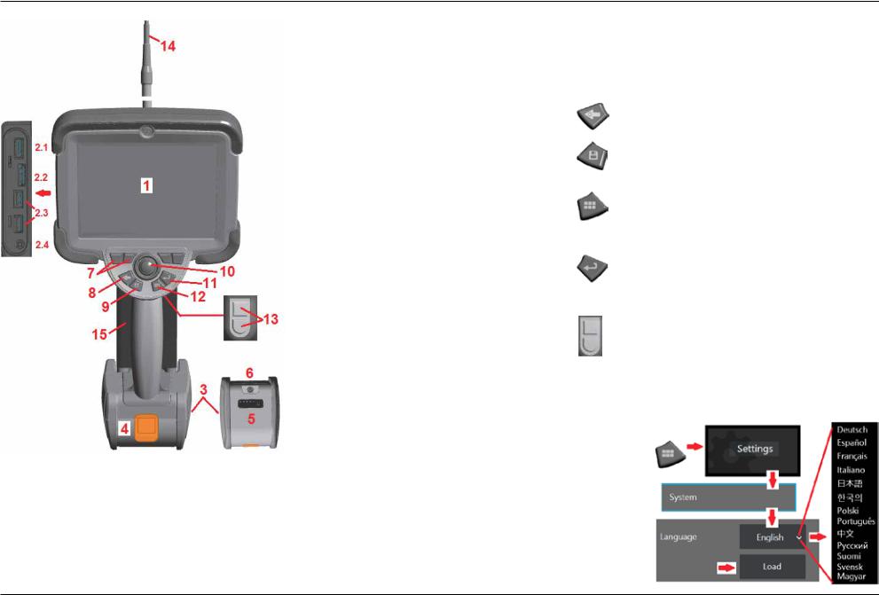
Component Identification
1 – LCD Touchscreen
2 – DisplayPort Output (2.1), USB 3.0 Client
Micro B Port (2.2), Two USB 3.0 Host
Type A Ports (2.3), 3.5 mm Headset/ Microphone Jack (2.4).
3 – Two-hour Lithium Ion Battery
4 – Battery Release Button
5 – Battery Charge Indicator
6 – AC Adaptor Input
7 – Function (or Soft) Keys (four total)
8 – Back Button: short press moves back one screen, long press moves to live screen. This also serves as the POWER ON button.
9 – Save Button: short press launches a Quick Save, long press opens or closes the Save Options Menu. Double press to record a Screenshot.
10 – Joystick Controls Articulation and Menu Navigation (push the joystick left/right/ up/down to navigate menus and sub-menus).
Hard |
Name |
Short |
Long |
Double |
Key |
|
Press |
Press |
Press |
|
|
|
|
|
|
Back |
Moves back one |
Moves to live |
|
|
button (and |
screen |
image |
|
|
Power On) |
|
|
|
|
Save |
Quick save |
Save with |
Record a |
|
button |
(assigns default |
options |
Screenshot |
|
|
name and |
available |
|
|
|
location) |
|
|
|
Menu |
Opens or closes |
Toggles |
|
|
button |
Global Menu |
between first |
|
|
|
|
and second |
|
|
|
|
rows of soft |
|
|
|
|
buttons |
|
|
|
|
|
|
|
Enter |
Toggles between |
Performs |
|
|
button |
live and frozen |
3DPM capture |
|
|
|
images. Also |
|
|
|
|
confirm selection |
|
|
|
|
(Done/Accept). |
|
|
|
|
|
|
|
|
Trigger |
Upper is same as |
Upper is same |
|
|
buttons |
Enter button |
as Enter |
|
|
(upper |
Lower toggles |
button |
|
|
and lower) |
Lower returns |
|
|
|
|
articulation mode |
|
|
|
|
between steer- |
articulation |
|
|
|
and-stay and |
system to |
|
|
|
steering modes |
neutral position |
|
|
|
|
|
|
11 – Enter Button: short press toggles between frozen and live frames and selects Done / Accept, a long press performs a 3DPM
Capture.
Note: Follow the selection sequence shown here to select the Operating Language.
12 –MenuButton: short pressopensorcloses theGlobalMenu, longpresstoggles betweenfirst andsecondlevelsoftbuttonrows.
13 – Trigger Button 1 (Upper): provides the same function as the Enter Button. Trigger Button 2 (Lower): short press toggles articulation mode between steer-and-stay and steering modes. When in steer-and-stay mode, a Lock icon appears. Long press returns the articulation system to the neutral (home) position.
14 – Insertion Tube/Camera assembly
15 – Interchangeable VideoProbe (Note: Includes Insertion Tube/Camera assembly)
10 |
08/2019 |
Touchscreen and Keys – Dual Control Systems
Most functions can be accomplished using the touchscreen or with a combination of keypressesandjoystickmovements.Thefollowingexamplesillustratevariouscontrol techniques that can be used on most Visual iQ display screens.
1 – Touch the lower left corner of the display screen (typically contains the GE Logo) or short-press the Menu key to open the Global Menu.
2 – The selected item in anymenu or list is identified by thisblue outline. Tap the display screen to select another item or to launch the selected item. Alternatively, use the joystick to select another item by moving the blue cursor, then short-press the Enter key to launch. Note that a short press of the Enter key accepts or launches most selected choices or actions.
3 – Tap the display to toggle between the upper and lower softkey bar (double-tap to hide or show the softkey and status bars). Alternatively, long-press the Menu key to switch between the upper and lower softkey bars.
4 – Tap anywhere on a displayed Live Image to freeze and unfreeze it. Alternatively, shortpress either the Enter key or the Upper Trigger key to freeze and unfreeze a live display.
Note that the Upper Trigger key performs the identical functions as the Enter key.
5 – Position two fingers on the display screen and move them apart to zoom in on a feature of the display (perform the opposite action to zoom out). Once zoomed (in a frozen image), you can drag with your finger to change the displayed view.
6 – Select the Zoom function using either soft keys or the touch screen (all displayed soft-key bar items can be selected either with the corresponding soft key or by tapping thetouchscreen).Usethejoystick to change the zoommagnificationbar(this and other blue bars can also be adjusted by dragging them using the touch screen), then select
Done. Once zoomed, you can use the joystick to move the displayed view.
7 – When the File Manager screen appears, the selected file or folder is identified by this blue outline. Tap the display screen to select another item or to launch the selected file or open the selected folder. Note that you can also display additional items (or directly access additional stored images) by simply swiping the display screen in any of the directions shown. Alternatively, use the joystick to select another item by moving the blue cursor, then short-press the Enter key to launch the file or open the folder.
8 – Select any feature in the Soft Key Bar by either touching that feature on the display screen (in this case, touching the box containing the words List View) or pressing the corresponding soft key.
Note: Connecting a Bluetooth or USB-wired keyboard allows for remote control of iQ functions and probe articulation. See Appendix O for a list of function key and keypress combinations equivalent to iQ button and joystick operations.
08/2019 |
11 |
Unpacking, Assembling, and Powering the Visual iQ
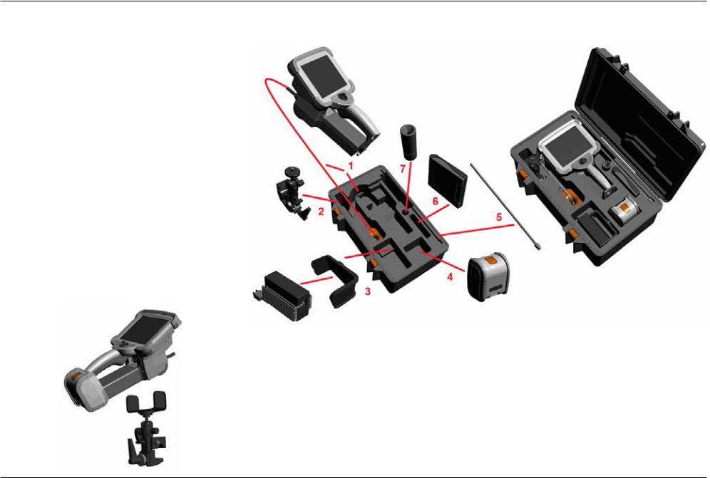
Unpacking and Putting Away the System (Small Case)
 Caution: If you do not pack the system carefully, as described here, damage might occur.
1 – The insertion tube (shown in red for clarity) is held in the case’s internal storage reel, which is accessed through the orange funnel shown here. Install the insertion tube before installing the probe-and-handset assembly and remove it after removing the probe-and-handset assembly. Be sure to straighten any loops or twists in the insertion tube before feeding it into the funnel. Note that the insertion tube’s rubber Torsional Strain Relief base should be routed through the case’s curved passage shown here.
 Caution: Before using the camera system, install an optical tip or the head guard, which prevents damage to the tip-attachment mechanism. Keep the head guard on whenever no optical tip is in place.
2 – Install clamp in the orientation shown here (clamp and mounting bracket assembly appears at left)
3 – Power supply / Battery Charger and Mounting Bracket are oriented and installed in this slot 4 – Battery must be removed prior to installing the iQ in the case.
5 – Rigidizer
6 – A case holding tips (or cleaning kit) fits in this slot.
7 – Gripper may be used alone, or with Rigidizer, to aid in orienting camera.
12 |
08/2019 |
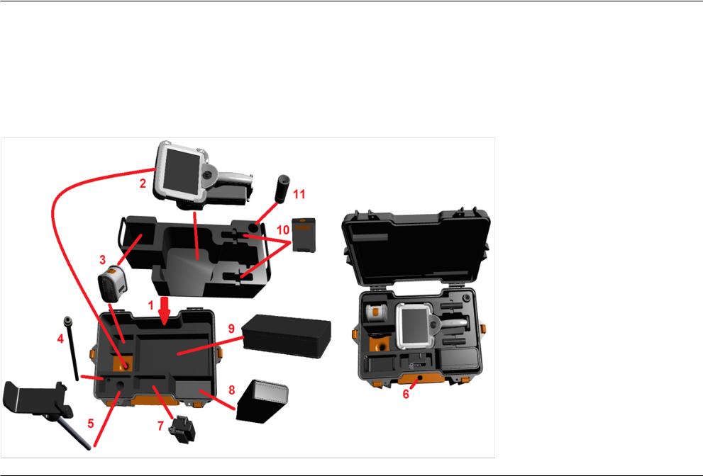
Unpacking and Putting Away the System (Large Case)
 Caution: If you do not pack the system carefully, as described here, damage might occur.
1 – Remove tray to access additional storage space.
2 – The insertion tube (shown in red for clarity) is held in the case’s internal storage reel, which is accessed through the orange funnel shown here. Install the insertion tube before installing the probe-and-handset assembly and remove it after removing the probe-and-handset assembly. Be sure to straighten any loops or twists in the insertion tube before feeding it into the funnel.
 Caution: Before storing the insertion tube, first remove the optical tip and install the head guard, which prevents damage to the tip attachment mechanism. Keep the head guard on whenever no optical tip is in place.
3 – Storage locations for two batteries. Battery must be removed prior to installing the iQ in the case.
4 – Rigidizer
5 – Mounting bracket and post
6 – Mounting bracket post fits in this hole
7 – Power supply / Battery Charger installed in this slot
8 – Extra Pod in case
9 – Extra VideoProbe in case
10 – Two cases holding tips and a cleaning kit fit in these slots.
11 – Gripper may be used alone, or with Rigidizer, to aid in orienting camera.
08/2019 |
13 |
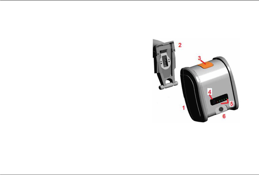
About the Battery
The Visual iQ is powered by a 10.8 V (nominal), 73 Wh, 6.8 Ah Lithium Ion battery.
Installing the Battery
Insert the battery into the handset. The battery is installed properly when the latching mechanism is engaged.
 Caution—Do not force the battery (1) into the handset (2), as damage may occur.
The battery is keyed and may only be installed in the proper orientation.
Removing the Battery
Press battery release button (3) to release the battery.
 Caution—Do not remove the battery while the system is operating.
Battery Charge Level
Check the battery charge by pressing the battery symbol (4) on the front of the battery.
Each light (5) represents approximately 20% of the battery charge capacity.
Charging the Battery
Connect the DC output of the battery charger into the Visual iQ battery (6) and then plug the included AC to DC power adaptor into a suitable AC power source. The LED battery lights will illuminate according to the amount of charge attained. The system may operate while charging.
Note: The battery may be charged while connected to an operating Visual iQ or while disconnected from the iQ.
Note: When the battery is fully charged, the LED battery lights will turn off.
Note: Battery run time approximately equals battery charge time; therefore, a two hour battery will take approximately two hours to charge. Charging time will be longer if the battery is connected to an operating Visual iQ system while charging.
Note: All batteries are shipped with a partial charge. Batteries should be fully charged prior to use.
14 |
08/2019 |
Supplying Power to the Visual iQ
The Visual iQ is powered by a 10.8 V (nominal), 73 Wh, 6.8 Ah Lithium Ion battery.
The battery is charged by connecting the power adaptor to the battery, then connecting the supplied AC-to-DC power adaptor to a suitable (100-240 VAC, 50-60 Hz, <1.5 A rms)
AC power source. The power adaptor delivers to the battery 18 Volts at 3.34 Amps.
Note: When powering a system with an AC power source, connect the power plug to a properly grounded source for reliable touchscreen operation.
Powering the Visual iQ On and Off
System Power On
Press and hold  untiltheunitturnson.ThebuttonsandLiquidCrystalDisplay(LCD) will light and begin the power-up sequence. After approximately 35 seconds, the system screen will display live video and on-screen controls. The system is now ready for use.
Note: All batteries are shipped with a partial charge. Batteries should be fully charged prior to use.
System Power Off
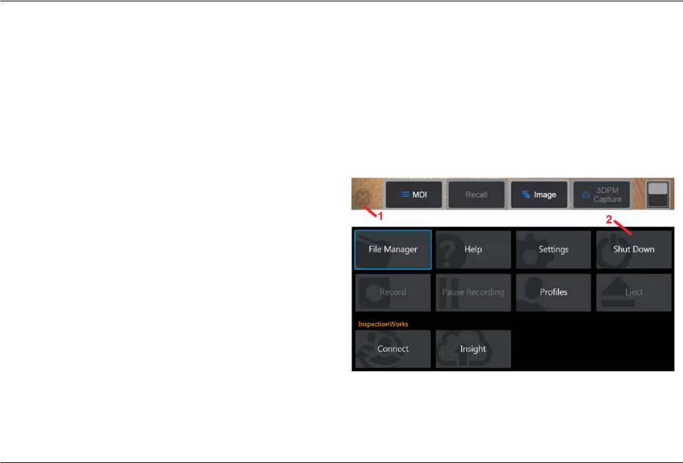
Touch the lower left corner of the display screen (which typically contains the on-screen
GE Logo (1) or the  hard key at any time to open or close the Global Menu, which
provides access to several features including Shut Down (2). Select Shut Down to power off the Visual iQ.
 Caution—Do not power off the Visual iQ by removing its battery. Only remove battery after powering off as described above.
08/2019 |
15 |
Changing Probes and Optical Tips
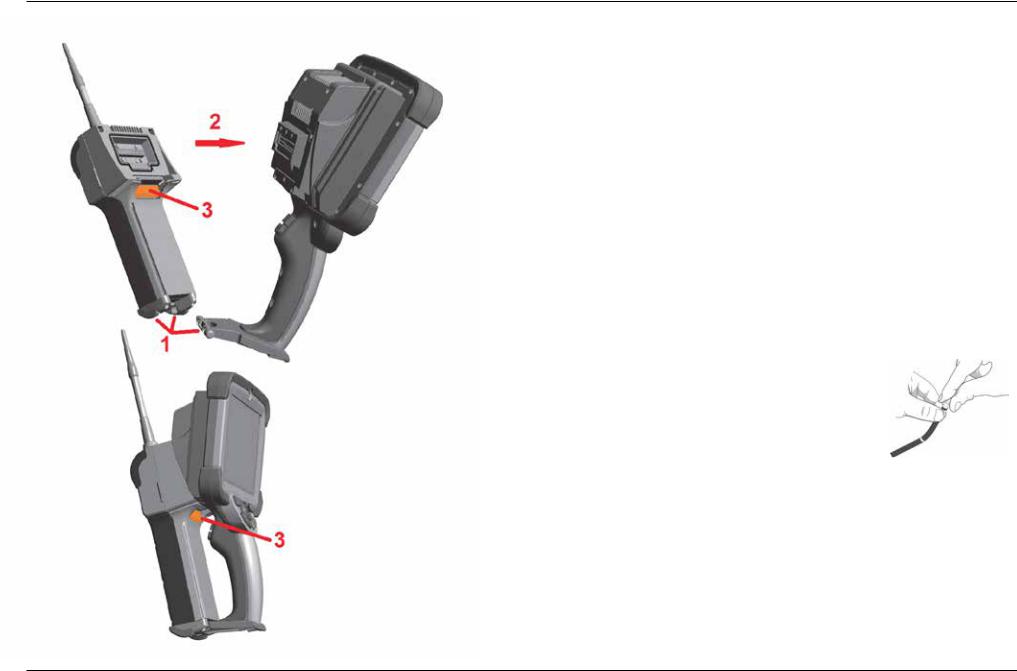
Attaching and Removing the Probe
To attach the probe to the handset:
1 – Insert the pin at the base of the handset into the mating groove at the bottom of the probe.
2 – Rotate the probe towards the back of the handset, applying enough pressure for the latching mechanism to “click.”
To remove the probe from the handset:
3 – Press this latching-mechanic's release button to separate the probe and handset.
Changing the Optical Tip
Optical tips are threaded onto the probe with a double set of threads to prevent them from falling into the inspection area. Each optical tip provides a unique depth of field, field of view, and direction of view. For a list of available tips, see Appendix B – Optical Tip Table.
 Caution—Use only finger pressure to remove or attach tips. Using force (including pliers or other tools) might damage the bending neck. Take care not to cross the threads. To reduce cross-threading risk: When installing a tip by hand (6.1mm & 8.4mm) or with an installation tool (4mm),rotatethetipcounterclockwisetolevel the threads before rotating clockwise to thread the tip on the camera. Reverse the leveling process when removing tips.
To Remove an Optical Tip: Support the bending neck and head of the probe with one hand, and with the other gently turn the optical tip counterclockwise (be sure to use a tip tool when removing 4.0 mm tips), Turn until the tip spins freely, indicating that it has cleared the first set of threads. Gently pull the tip away from probe and continue turning counterclockwise, engaging the second set of threads. Turn until you can remove it.
To Attach an Optical Tip: Verify that the optical tip and camera head threads are clean, then grasp the head of the probe with one hand, and with the other gently turn the tip clockwise.
Turn until it spins freely, indicating that it has cleared the first set of threads. Gently push the tip in, then turn clockwise again, engaging the second set of threads. Turn until finger tight.
 Caution—Donotover-tightentips.Pullonthetipgentlytoverifythatitissecurelyattached.
If the second set of threads does not engage, turn the tip slightly in a counterclockwise direction to allow the threads to levelize.
Note: Measurement tips must be tightened firmly to ensure accuracy.
16 |
08/2019 |
Setting Up the Visual iQ Operating System
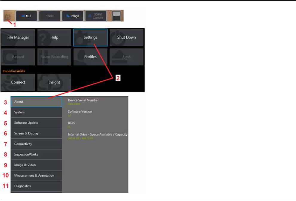
1 – Select the lower left corner of the display (which typically contains the on-screen
GE Logo) or the  hard key at any time to open or close the Global Menu, which provides access to several features including the Settings Menu.
2 – Tap to open the Settings Menu.
3 – Lists the device’s serial number and software version.
4 – Access to set a Password, Restore Defaults, adjust Date, Time, and operating Language, and alter various other system settings. Click here to learn more about the System Menu.
5 – Control automatic software update capability and manually update through web connection or connected USB drive.
6 – Allows the user to turn various on-screen indicators on and off as well as adjust display brightness. Click here to learn more about Display Setup.
7 – Allows the user to turn Wi-Fi and Bluetooth connections on and off as well as work with networks and identify folders for file sharing. Click here to learn more about
Connectivity Settings.
8 – Settings related to optional internet service that enables video collaboration between inspectors and remotely located experts.
9 – Allows the user to specify the default directories into which image files and videos arestored.Alsousedtoselectimagefiletype,videoformat,andsound-relatedsettings.
Controls MDI Annotation and imports Distortion Correction Tables. Click here to learn more about Image and Video Settings.
10 – Allows the user to set their preferred measurement units (inches vs. mm), manage and verify measurement tips, select the desired annotation style, and import and export preset annotations.
11 – Generates a Troubleshooting Log to be emailed to and evaluated by GE Technical Support. If log generation is required, GE Technical Support will guide the user through the process.
08/2019 |
17 |
Working with Profiles
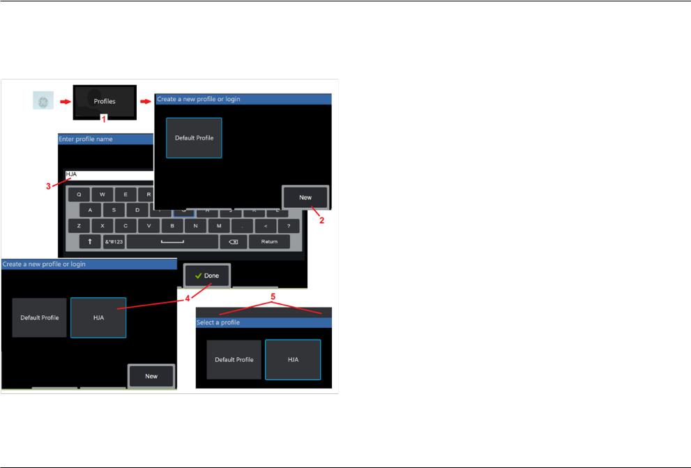
AProfiledefinesseveralparametersettings.Aslongasmorethanoneprofileisavailable,
(the Visual iQ is delivered with only a Default Profile), the operator is asked to select a Profile every time the system is powered on. Follow these instructions to create a new profile or select an existing one.
1 – To create a New Profile, touch the lower left corner of the display (or press the  hard key) to open the Global Menu, then select Profiles.
2– In this case, the Default Profile is active and it is the only one defined. Select New to create a new profile.
3– The Virtual Keyboard opens. Enter a Name for the new profile.
4– After entering a name and clicking Done,thenewprofileisaddedtothelistofavailable profiles. This profile includes the settings in place, at the time of its creation, for each of the parameters listed below. Anytime the profile is reactivated, the system will apply the settings associated with the activated profile. The parameters affected include:
System Settings Including:
Watermark Logo ON/OFF
Time Format
Date Format
Language
Power Management
USB Slave Mode
Steering Sensitivity
Screen & Display Settings – All Parameters
Connectivity Settings Including:
Wi-Fi on/off
Bluetooth on/off
Image & Video Settings – All parameters except Distortion Correction Table
Measurement & Annotation Including:
Presets
Zoom Window
3DPM Mask
3DPM Save Format
Stereo Index
Stereo Index Minimum
Units
5 – Each time the Visual iQ is powered on, you’ll be asked to select from the list of availableprofiles.SelectingtheDefaultProfilereturnsthesettingsforallprofile-controlled parameters to those specified by the default profile.
18 |
08/2019 |
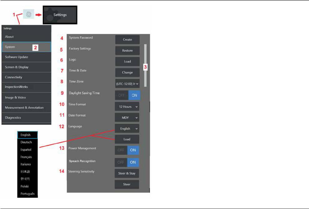
System Setup
1 – Tap the on-screen GE Logo (or press the  hard key) to open the
Global Menu, then open the Settings Menu.
2 – Select to alter the system-specific settings shown here.
3 – Drag your finger up or down the screen. This bar will move to show the current position among the list of system-specific settings.
4 – Tap to open the virtual keyboard and create or change a System Password. Once created, accessing the iQ’s operating screens requires first entering the password. This password is for the entire system and is not associated with the active profile.
Note: Entering a password requires the Default Profile be active.
5 – Select and follow the on-screen prompts to restore the active Profileto the Factory Default Settings.
Loading a Logo
AlogocanbeloadedontothedisplayscreenprovideditisPNGfiletype(withdimensions smaller than 140 x 140).
6 – Select Load, then navigate the instrument or an external drive to select any PNG file type as the on-screen logo. Click here for more information on creating and loading a personalized logo file.
Setting Date and Time
7 – Adjust Time and Date settings.
8 – Select the Time Zone in which you are operating.
9 – Indicate whether or not the instrument should automatically adjust for time changes due to Daylight Savings.
08/2019 |
19 |
10 – Specify 12 or 24 hour Time Format.
11 – Specify DMY, YMD, or MDY as the Date Format.
Loading and Selecting the Operating Language
12 – Choose from the operating Languages currently available for use. Selecting Load allows you to upload a new version of any of the existing translations available in the iQ.
Onceselected,theFileManagerscreenallowsyoutonavigatetothemodifiedtranslation file.
Other System Settings
13 – Setting Power Management to ON conserves battery power by putting the Visual iQ intosleepmodeafter10minutesofinactivity.Wheninsleepmode,inwhichonlythehard keys remain lit, touching any key or the joystick returns the iQ to a fully powered state.
Steering Sensitivity Settings
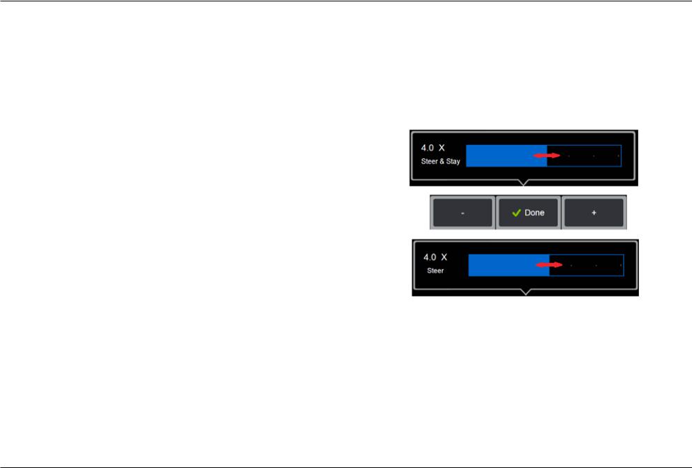
14 – The user can select from two probe steering modes: Steer or Steer and Stay™. In either mode, the bending neck articulates to follow the joystick motion. The modes differ in how they behave after the bending neck is positioned (click here to learn about thedifferencesbetweenthesemodes). Select either button shown here then drag the setting bar to set the sensitivity of either Steer or Steer and Stay mode. The higher the setting, the more the bending neck will articulate with a change in joystick position. For instance, increasing the setting from 2.0 to 4.0 means that a similar joystick movement will produce a greater amount of bending neck articulation.
20 |
08/2019 |
Screen & Display Setup
1 – Tap the on-screen GE Logo (or press the  hard key) to open the
Global Menu, then open the Settings Menu.
2 – Select to alter the display-screen appearance and operation.
3 – Turn the display screen’s touch-sensitive control ON or OFF. Once turned OFF, the icon shown here appears at the top of the display screen. Once disabled, use a combination of joystick and hard key press to re-enable the touchscreen.
4 – The Tip Map (shown here) graphically represents the extent to which the optical tip is articulated by positioning a bright dot at some distance from the crosshairs. The closer the dot appears to the center of the crosshairs, the straighter the tip’s position.
5 – The customizable watermark shown here appears in the bottom left corner of the display screen. Tapping this location opens the Global Menu. Turning this icon OFF causes it to disappear while tapping in its former location still opens the menu.
6 – Turn the displayed date and time, which appears on the status bar at the display’s upper right corner, ON or OFF.
7 – Select to turn the Sound Recording and/or Sound Recording Muted icons (shown here)ON or OFF. These icons appear in the display’s bottom right corner when recording video with an audio stream. Note that when these icons are visible (turned ON),selecting the onscreen icon mutes or unmutes the sound recording.
8 – Display or hide touch-screen pause and play controls during video recording.
9 – Control the display’s brightness by using your finger to drag this bar right or left (or
select with the joystick, press  and then position with the joystick).
08/2019 |
21 |

Connectivity Setup
1 – Tap the on-screen GE Logo (or press the  hard key) to open the
Global Menu, then open the Settings Menu.
2 – Select to work with settings that control the connection of the Visual iQ to WiFi networks and Bluetooth devices.
3 – Turn the WiFi connection ON or OFF. Once turned ON, the icon shown here appears at the top of the display screen.
Making Bluetooth Connections
4 – Turn the Bluetooth connection ON or OFF. Once turned ON, the icon shown here appears at the top of the display screen. The icon is gray if Bluetooth is ON or white if Bluetooth is ON and paired with a device. Then, select Connect to display a list of available Bluetooth Devices to which the iQ can connect.
5 – Available Bluetooth Devices that appear on this list can be paired with by simply tapping the on-screen listing. Note that pairing a keyboard may require inputting a PIN. When the device status switches from Not Paired to Paired, it is in Bluetooth communication with the Visual iQ. Note: Connecting a Bluetooth or USB-wired keyboard allows for remote control of iQ functions and probe articulation. See Appendix O for a list of function key and keypress combinations equivalent to iQ button and joystick operations.
Working with WiFi
6 – Select Connect to display a list of available WiFi networks to which the iQ can connect. Tap the screen to select an already known network from this list. (Select Manage Known Networks at any time to review the list of already-recognized networks and/or Edit the list by removing networks to which you no longer wish to automatically connect). Once Edit List is selected, tap the blue corner of any network to delete it from the list.
7 – If prompted by the onscreen instructions, use the Virtual Keyboard to enter the network’s password.
8 – Selecting Add Network allows you to enter the
SSID and security information for a hidden network not shown above.
22 |
08/2019 |
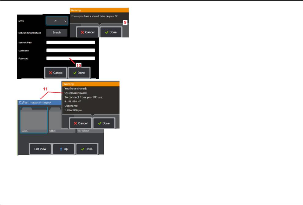
Mapping the Network Drive and Sharing Folders
9 – If you choose to give the Visual iQ’s File Manager access to a folder on a networkconnected computer, click on Setup (see above) to open the network-mapping process shown here. Next, select Done to confirm that the network connected PC has at least one folder identified for sharing.
10 – Enter the drive letter you wish to assign (in the Visual iQ’s File Manager) to the shared folder, then input the complete path to the folder on the network-connected PC. Following is an example of a complete path to insert in the Folder line: \\Device Name\TestShare Folder. When the folder path and username/password (assuming it is a password protected network) have been entered, click Done.
11 – To share one of the Visual iQ’s folders with a network-connected computer, click on Setup (see above) to open the file-selecting process. The path in the blue bar shown here identifies the folder that will be shared. Next, select Done to display the Warning statement listing the folder that will be shared, and select Done again to confirm that the identified folder is the one you wish to share with a network-connected PC.
12 – Set the USB Slave Mode to Mass Storage or Disable. When set to Mass Storage, a connected computer can work directly with files stored on the Visual iQ’s hard drive for file management purposes. In this state, the iQ will not perform inspection functions. When file management functions are complete, change setting to Disable to return inspection functionality.
08/2019 |
23 |
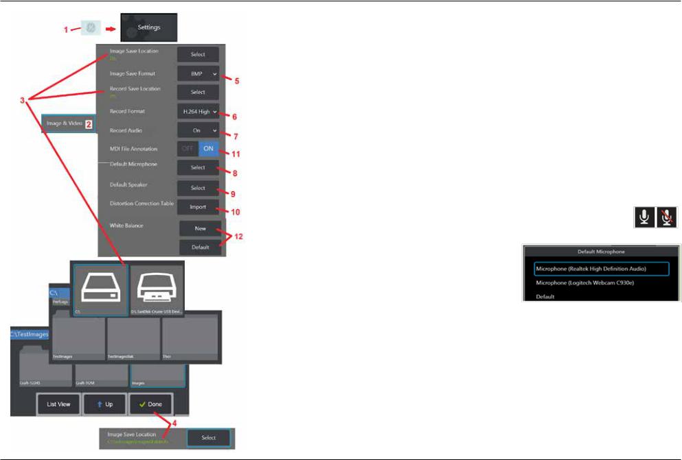
Image & Video Setup
1 – Tap the on-screen GE Logo (or press  ) to open the Global Menu, then open the Settings Menu. 2 – Select to change Image and Video related settings and defaults.
3 – Follow the procedure shown here to change either the Image Save Location or Video Save Location. These represent the two locations where quick-save images or videos are automatically stored. In the example shown here, these locations are both initially set to the D: drive. Press the Select soft key and then choose the desired directory path. When the desired storage location is opened, select the Done soft key to complete the process.
Note: The DVD drive may not serve as either the default or alternative saving location. Files must first be saved in a directory located in the instrument’s memory or on a connected USB storage device. Files can later be copied and pasted to optical media in an attached DVD drive.
4 – Using the process outlined above, the default Image Save Location is changed to C:\TestImages\Images\ FolderA\. This is the location where quick-saved images are stored (Click to learn more about Saving Images).
5 – Choose either BMP or JPEG as the default image file type.
6 – Set the video recording format to either H.264 High or H.264 Low. (Click for Working with Video).
7 –Determinesifthemicrophoneicon(atright)appearsinthedisplay’sbottomrightcornerduring video recording. When displayed, tap the icon to mute or unmute the recording of sound along with video. Click here to learn more about muting or turning sound
ON when recording live video.
8 – When set to Default, the system will normally recognize the connected Microphone. Alternatively, choose a microphone from those available (choices are only those devices already connected to the Visual iQ or paired via Bluetooth).
9 – When set to Default, the system will normally recognize the
connected Speaker. Alternatively, choose a speaker from those available (choices are only those devices that are already connected to the Visual iQ or paired via Bluetooth).
10 – Should a not-yet-defined tip configuration require an alternative Distortion Correction Table, Contact GE Technical Support. A table supplied by GE Technical Support will include instructions on how to Import the file.
11 – When set to OFF, the menu-directed inspection stage name is not saved in the image but will still appear during the MDI process.
Executing a White Balance
A white balance corrects the color so that white appears white despite any slight hues that may exist under the lighting conditions present when performed.
12 – Select New and follow the prompts or select Default to restore factory color settings.
24 |
08/2019 |
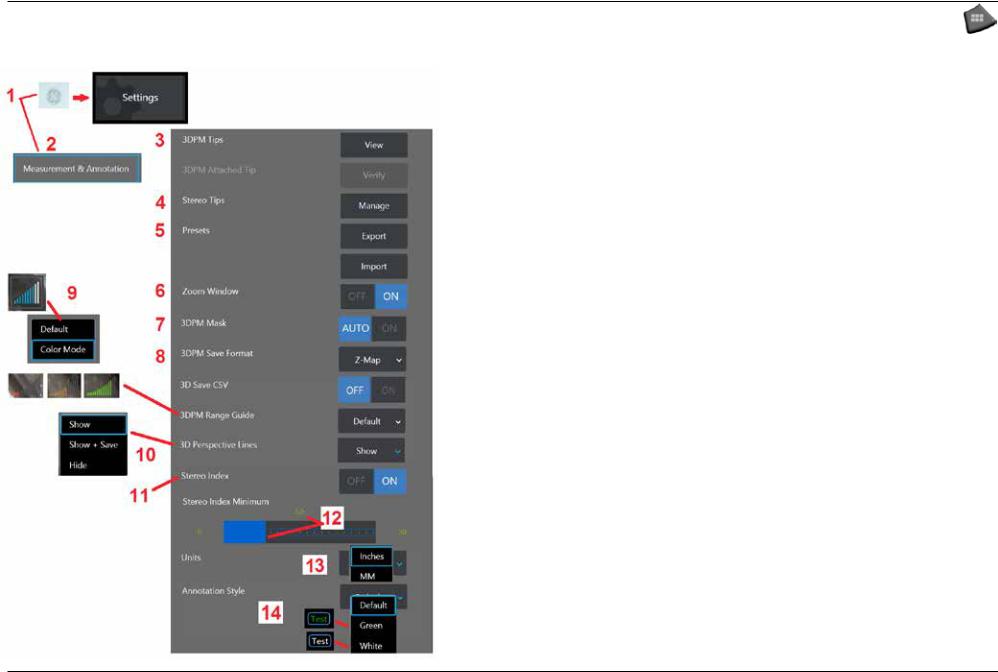
Measurement & Annotation Setup
1 – Tap the lower-left corner of the display (typically contains a GE Logo) or (or press the hard key) at any time to open the Global Menu, which provides access to the Settings Menu.
2 – Select to alter the Measurement and Annotation-specific settings shown here.
3 – View the list of 3DPM Tips already calibrated for use with the attached probe.
4 – Select to view a list of Stereo Tips already-calibrated for use with the attached probe. The Add Tip and Edit List options are not intended for general use. Deleting a tip through the Edit List option will permanently remove that tip’s calibration data requiring the probe and tip to be returned to an authorized GE Inspection Technologies service center for re-calibration.
5 – Save Preset Annotation (notes) to an external storage device or Import preset notes to the instrument from an external device.
6 – Displays or removes the Zoom Window (used for detailed cursor placement during measurement).
7 – Select AUTO to show the 3DPM red/yellow un-measurable pixel mask only when a cursor is placed on a red/yellow pixel. Select ON to always show the pixel mask when measuring.
8 – Select Z-Map for most usage. P-Map images contain additional data and may be requested by GE Technical Support to aid in troubleshooting.
9 – Determine the type of Range Guide to display during 3DPM measurement. As the tip-to-target distance decreases, the 3DPM Range Guide displays an increasing number of illuminated bars. In Default mode, the illuminated bars are all blue. In Color Mode, the bar color transitions from red, when few bars are illuminated, to green, when most of the bars are illuminated. Click here to learn more about making 3DPM measurements and the Range Guide.
10 –Displaysfourdottedlinesinthefull-imagepointcloudview.Theselinesrepresentfieldofview, providing the user with a better sense of probe orientation relative to the viewed surface. When using a measurement plane in conjunction with a Point-to-Line, Area, or Depth measurement type, an Edge View Angle is also included in both full-image and measurement-image point cloud views. These lines may be Hidden, Shown in the point cloud view during measurement or Shown and Saved along with the saved measurement image.
11 – Controls the display of the Stereo Index, which appears during Stereo Measurement. Click here for more about Stereo Index.
12 – Sets a threshold value for the Stereo Index below which the index flashes during Stereo
Measurement. This may be used to warn the user of low-index measurements where the accuracy may be reduced.
13 – Specify the unit of measurement as Inches or Millimeters.
14 – Annotation may be added to any frozen or recalled image. Select the Annotation Style to change the color of the letters displayed. Text colors available include black (Default), Green, and White.
08/2019 |
25 |
Capturing and Adjusting Images
Steering the Probe
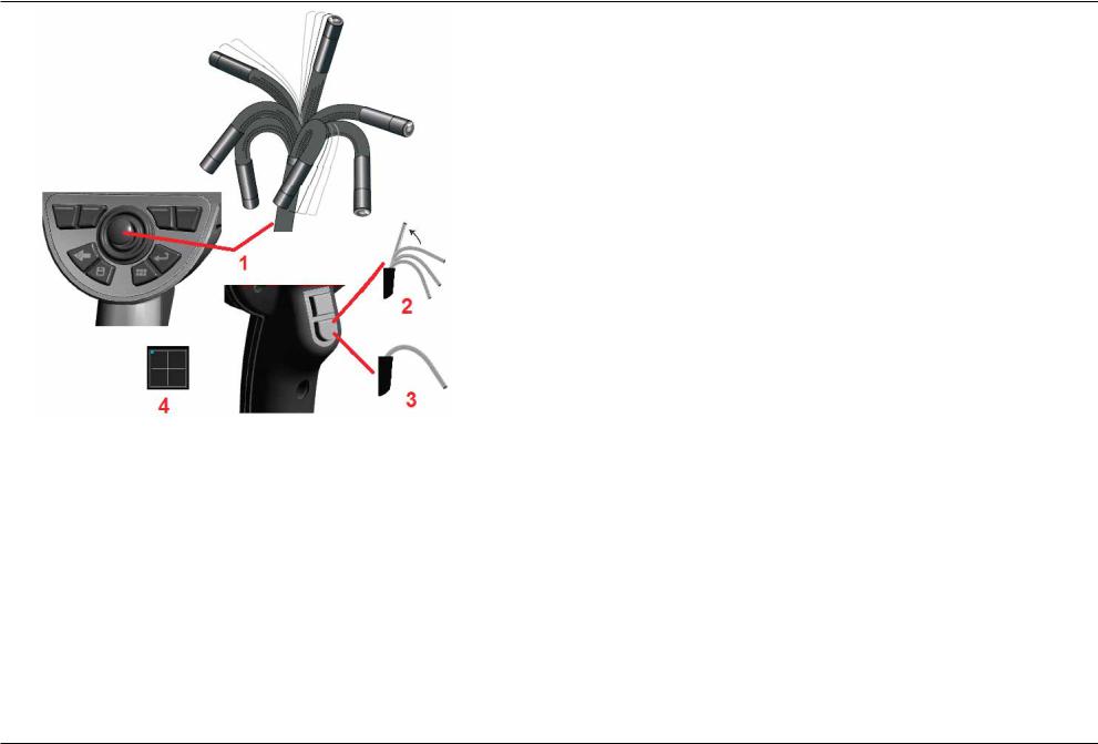
When you are viewing a live image, you can aim the probe’s camera by controlling its bending neck.
1 – Steering the Bending Neck: While viewing a live image, move the joystick toward the feature you want to see. The bending neck articulates so that the probe tip moves in that same direction.
2 – Straightening the Bending Neck: Long press this button to HOME or straighten the bending neck for safe withdrawal and storage of the insertion tube.
3 – Setting the Steering Mode: Short press this button to choose between Steer or Steer and Stay mode. In either mode, the bending neck articulates to follow the joystick motion. They differ in how they behave after the joystick is released (click here to learn how to setup the sensitivity of either mode). Steer mode allows the bending neck to drift towards a straight position when the joystick is released. Steer and Stay mode holds the bending neck in its articulated position when the joystick is released. If you move
the joystick while in Steer-and-Stay mode, the bending neck articulates. When you stop
moving the joystick, the bending neck stays in the new position. This  icon appears when in Steer and Stay mode.
Note: Connecting a Bluetooth or USB-wired keyboard allows for remote control of iQ functionsandprobearticulation.SeeAppendixOfor a list of function key and key-press combinations equivalent to iQ button and joystick operations.
4 – Tip Map. This on-screen icon indicates the relative positions of the steering motors. When the illuminated dot appears in the center of the crosshairs, the motors are centered. The bending neck position generally follows the motor positions but is affected by the shape of the insertion tube and other mechanical effects. The further the dot appears from the center of the icon, the more the bending neck is articulated. Depending on the rotation of the insertion tube and camera, the viewing area may or may not align with the direction indicated on the Tip Map.
Guiding the Insertion Tube Into the Inspection Area
With the desired optical tip installed, guide the insertion tube into the inspection area. Use your hands to push the tube until it reaches an area you want to inspect. Twist the insertion tube gently to bring the desired scene into view. Accessories are available to make it easier to maneuver the tube:
•Rigidizers: Rigid or semi-flexible guide tubes (available in different lengths) keep the tube supported as you insert it or allows the tube to span a recess.
•Grippers: Cylindrical handles that slide over the insertion tube to make it easier to control. Grippers are threaded to connect to rigidizers and to access port couplers.
Temperature Sensor Warnings
When excessive temperature is detected, the applicable icon displays in the status bar, and one of the warning messages listed below appears across the top of the display screen:
•Probe tip temperature has entered the WARNING Zone—this message displays in an
orange banner when tip temperature exceeds approximately 95°C and  appears in the status bar.
•Probe tip temperature has entered the CRITICAL Zone—this message displays in a
red banner when tip temperature exceeds approximately 100°C and  appears in the status bar.
•System is overheated, system shut down initiated—this message displays in a red banner when internal temperatures exceed limits. Shutdown automatically initiates
and  appears in the status bar.
When either the CRITICAL Zone or System Overheat warning appears, take immediate action to lower the temperature to which the indicated component is exposed.
26 |
08/2019 |
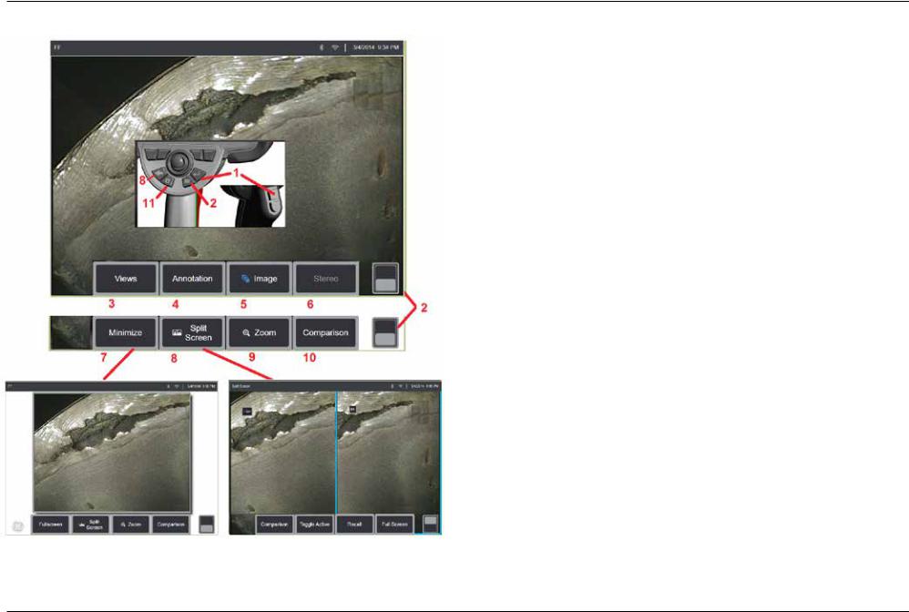
Freezing the Image
Freeze an image to temporarily capture it for review or adjustment. Moving the joystick in a frozen view does not articulate the probe tip.
1 –Brieflypresseitherofthesekeysortapanywhereonaliveon-screenimagetofreeze
the display. The  icon appears in the upper left corner of the display and the soft key menu opens, allowing for adjustment of the frozen image. Reverse this process (or
press  ) to unfreeze the display.
2 – Tap (or press and hold the  key) to toggle between the upper and lower soft key menus. Double tapping in this location hides or displays the soft keys and status bar.
3 – Select any one of up to four Views available when a 2D image is frozen or six Views when a 3DPM image is recalled (click here to learn more about each view).
4 – Add notes or arrows to the frozen image (Click here to learn more about annotating images).
5 – Select and adjust four image transformation settings including Brightness, Distortion Correction, Invert, and Inverse+. (Click here to learn about image settings).
6 – When a stereo tip is calibrated to the system, Stereo appears in white text. Press to perform stereo measurement. If no stereo tips are calibrated, Stereo appears in gray and may not be selected. (Click here to learn more about Stereo Measurements).
7 – Minimize the image to view unobscured by soft keys and status bar.
8 – Opens a Split Screen showing both frozen and live images. Press Full Screen to return to single screen view. (Click here to learn about working with Split Screens).
9 – Zoom in or enlarge a portion of the frozen image (Click here to learn about the
Zoom feature).
Note: If you zoom in on a frozen image and then move the joystick or drag the image with your finger, the image pans as the system electronically reviews the entire image.
10 – Measure features of the frozen image (Click here to learn about Comparison measurements).
11 – Press or press-and-hold to Save the frozen image (Click here to learn about the Save feature). Double press this key to save a Screenshot of the display screen.
08/2019 |
27 |
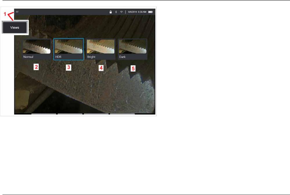
Selecting a View
When a 2D image is frozen (or a 3DPM image is recalled), the user can select from various Views as described below.
1 – Anytime an image is frozen, select to choose from all available View options.
2 – Displays a normal dynamic range image created by applying Adaptive Noise Reduction (ANR) processing to live video frames prior to the freeze request.
3 – HDR is a high dynamic range image generated by combining normal brightness ANR images captured before the freeze request with images of different brightness levels captured after the freeze request. This reduces the glare (number of saturated pixels) and increases brightness in dark areas.
4 – Displays a view similar to HDR but gives up some detail in bright areas to further brighten dark areas.
5 – Displays a view similar to HDR but gives up brightness in dark areas to show more detail in bright areas.
Note: To optimize the quality of all captured images, hold the probe tip still at the time of capture. Increasing the live image brightness prior to image capture will improve the quality of the "HDR" and "Bright" images in darker areas.
Note: Point Cloud and Depth Profile views are only available when working with 3DPM and 3DST images. Click here to learn more about working with these views.
Note: Once an image is saved with any one of these View options active, only that option and Normal are available when the saved image is recalled.
28 |
08/2019 |
Saving Image Files
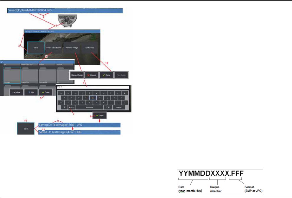
Image files can be stored in the Visual iQ or a detachable device. The Quick-Save feature stores a file with a default name and file type in a default directory (Click here to learn more about setting default file names, types, and directories).
Alternatively, use the Save Options Menu.
1 – Perform a short press of this hard key to Quick Save the displayed image in the default directory. A long press of this key opens the Save Options Menu. Double pressing this key saves a Screenshot of the display screen.
Note: Screenshots are BMP image files of the display screen, do not contain RVI data of any type, are stored in an automatically created subfolder titled “Screenshots,” and are assigned the auto-generated image file name but identified with the addition of the letters “ss.”
Note: The DVD drive may not serve as either the default or alternative saving location. Files must first be saved in a directory located in the instrument’s memory or on a connected USB storage device. Files can later be copied and pasted to optical media in an attached DVD drive.
2 – At all times, the intended saving location (in this case the Dev directory located on the
D drive) is listed here. After a file is stored, the status bar at the top of the screen indicates “Saved.” The file name (described below) and format are also listed.
Note: Each time files are pasted to the DVD drive, the optical media is auto-ejected to avoid loss of data.
3 – While in the process of assigning an alternative name or destination for the image file, the status bar at the top of the screen indicates “Saving.”
4 – Choose an alternative directory into which the file will be stored.
Note: Tap and open the target folder
5 – Tap to complete the target directory selection.
6 – Select to Rename the file prior to saving. The virtual keyboard opens.
7 – Select to choose from numeric characters or symbols. 8 – Tap after typing the desired name.
9 – The status bar now indicates the new target directory (in this case, TestImages) and the new file name (Trial 1).
10 – Tap to complete the saving process.
11 – The status bar now indicates that the file has been “Saved.”
12 – Add audio comments to the file before completing the saving process (Click here to learn more about recording audio comments).
08/2019 |
29 |
Working with a Recalled Image
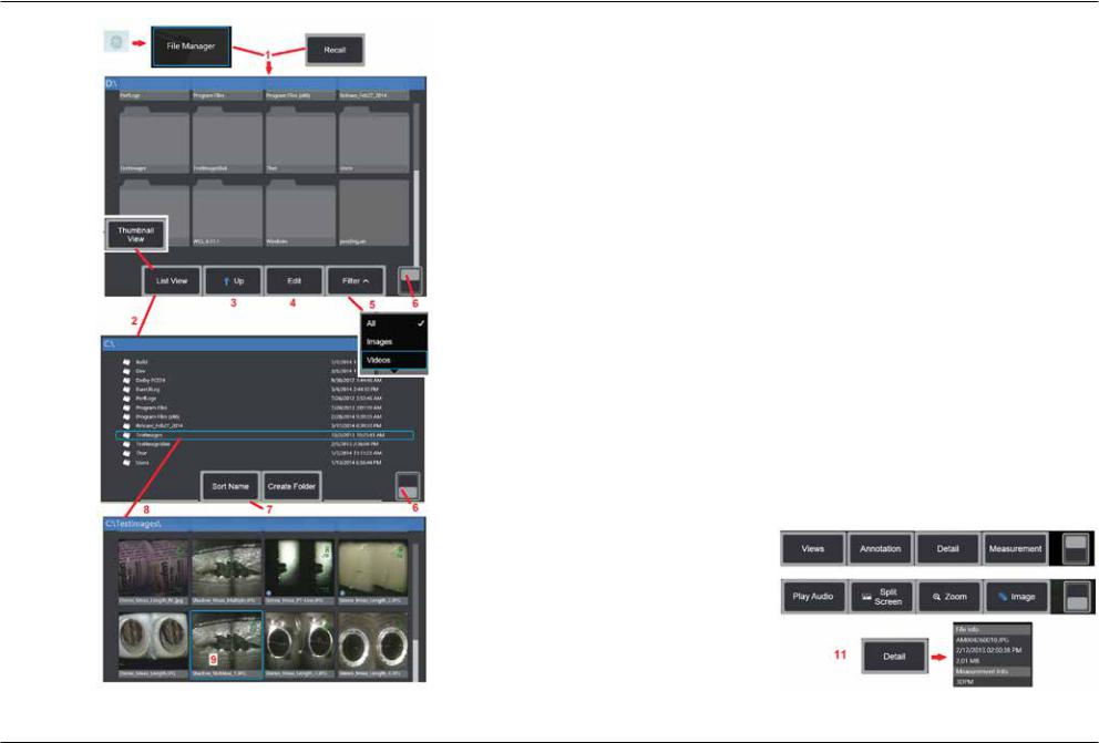
Image and video files can be stored in the Visual iQ or a detachable device. The Recall feature allows these stored files to be displayed, measured, and annotated. Follow these steps to locate and Recall a stored file:
1 – Recall a stored image or video by tapping the on-screen GE Logo (or press the  hard key) to open the Global Menu, then select File Manager.
Note: Selecting the Recall soft key (when enabled) automatically opens the last saved image (provided one has been saved since the iQ was last powered ON). Moving the joystick (or dragging the display with your finger) left or right recalls other images stored in the same folder as the originally recalled image.
2 – Controls the File Manager’s appearance (both Thumbnail and List Views areshownhere).
3 – Select to navigate to the next higher directory within the File Manager.
4 – Select to Copy, Rename, and otherwise Edit stored files (Click here to learn more about the file Edit feature).
5 – Choose which file types to display.
6 – Tap to switch between the Soft Key Bar’s top and bottom row. Double tapping in this location hides or displays the soft keys and status bar.
7 – Determine the order in which folders or files are listed (by date or alphabetical order).
8 – Tap screen to select the folder to open.
9 – Tap screen to select the file to Recall.
10 – Oncean image is recalled, variousactions can betaken (see soft keymenus below). Click on any of the following to learn more about the function:
-Select the displayed View -Annotate by adding text or arrows -Measure image features
-Play recorded audio
-Open a Split Screen to display any two images (live, frozen, or recalled)
-Use Zoom to magnify -Adjust the Image
11 – Press to open an onscreen list of the displayed file’s Detailed properties.
30 |
08/2019 |
 Loading...