


 Loading...
USM 36
Technical Reference and Operating Manual
This issue 2 (12/2013) applies to the following software version: 4.00 (August 2013)
You will find the software version and the serial number of your instrument on the second operating level (CONFIG1 - ABOUT)
© GE Sensing & Inspection Technologies GmbH | Technical content subject to change without notice.
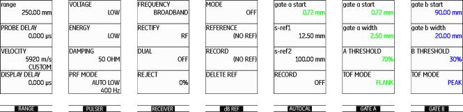
First operating level (Base)
To change between the first and the second operating level press Home key for 2 seconds.
USM 36 |
Issue 2 (12/2013) |
0-3 |
First operating level (Options)
To change between the first and the second operating level press Home key for 2 seconds.
0-4 |
Issue 2 (12/2013) |
USM 36 |

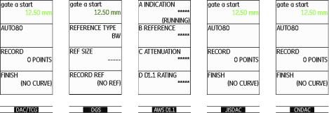
Second operating level
USM 36 |
Issue 2 (12/2013) |
0-5 |
Second operating level (continued)
0-6 |
Issue 2 (12/2013) |
USM 36 |
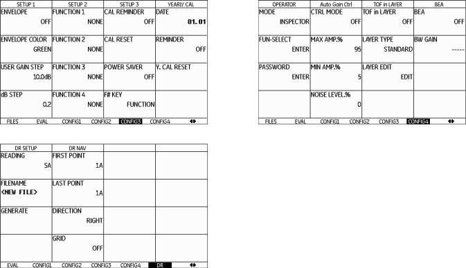
Status display icons
Icon Meaning
SD memory card is inserted,
flashes when the SD card is accessed
Freeze active (Freeze),
Display is „frozen“.
Magnify gate is active
Icon Meaning
Angle-beam probe 30° … 90°, flat surface, Reflection from the backwall
Angle-beam probe 30°, curved surface, Reflection from the inner surface of tube
Angle-beam probe 80°, curved surface, Reflection from the outer surface of tube
Pulser-receiver separation is turned off
Pulser-receiver separation is turned on
Pulser-receiver separation is turned on and set to through-transmission mode
Angle-beam probe 90°, surface wave
DAC mode = TCG is active
DGS reference echo has been recorded
Reject function is active
AGT is active
DGS reference echo has been recorded, transfer loss > 0
dB REF is active
Calibration reminder
USM 36 |
Issue 2 (12/2013) |
0-7 |
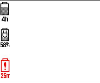
Power level indicators
Icon Meaning
Battery charge level, remaining operating time
in hours (approximate value)
Charger/power adaptor is connected, percentage of battery charge level (approximate value)
Warning: Low battery charge level, remaining operating time
in minutes (approximate value)
0-8 |
Issue 2 (12/2013) |
USM 36 |
Keypad functions
1 |
|
|
2 |
|
|
|
|
|
|
|
|
|
|
|
2 |
|
3 |
1 |
Left rotary knob for direct gain adjustments |
|||||||||||||||||
|
|
|
|
|
|
|
|
|
|
|
|
|
|
|
|
|
|
|
|
|
|
|
|
|
|
|
|
|
|
|
|
|
|
|
||
|
|
|
|
|
|
|
|
|
|
|
|
|
|
|
|
|
|
|
|
|
|
|
|
|
|
|
|
|
|
|
|
|
|
|
2 |
Selection keys, for selecting and confirming, |
|
|
|
|
|
|
|
|
|
|
|
|
|
|
|
|
|
|
|
|
|
|
|
|
|
|
|
|
|
|
|
|
|
|
|
3 |
for Zoom (long key press) |
|
|
|
|
|
|
|
|
|
|
|
|
|
|
|
|
|
|
|
|
|
|
|
|
|
|
|
|
|
|
|
|
|
|
|
||
|
|
|
|
|
|
|
|
|
|
|
|
|
|
|
|
|
|
|
|
|
|
|
|
|
|
|
|
|
|
|
|
|
|
|
||
|
|
|
|
|
|
|
|
|
|
|
|
|
|
|
|
|
|
|
|
|
|
|
|
|
|
|
|
|
|
|
|
|
|
|
Right rotary knob, for selection of function group or |
|
|
|
|
|
|
|
|
|
|
|
|
|
|
|
|
|
|
|
|
|
|
|
|
|
|
|
|
|
|
|
|
|
|
|
|
||
|
|
|
|
|
|
|
|
|
|
|
|
|
|
|
|
|
|
|
|
|
|
|
|
|
|
|
|
|
|
|
|
|
|
|
|
function, changing settings |
|
|
|
|
|
|
|
|
|
|
|
|
|
|
|
|
|
|
|
|
|
|
|
|
|
|
|
|
|
|
|
|
|
|
|
4 |
A-Scan freeze direct access key |
|
|
|
|
|
|
|
|
|
|
|
|
|
|
|
|
|
|
|
|
|
|
|
|
|
|
|
|
|
|
|
|
|
|
|
||
|
|
|
|
|
|
|
|
|
|
|
|
|
|
|
|
|
|
|
|
|
|
|
|
|
|
|
|
|
|
|
|
|
|
|
||
|
|
|
|
|
|
|
|
|
|
|
|
|
|
|
|
|
|
|
|
|
|
|
|
|
|
|
|
|
|
|
|
|
|
|
5 |
Programmable function keys F1 … F4, |
|
|
|
|
|
|
|
|
|
|
|
|
|
|
|
|
|
|
|
|
|
|
|
|
|
|
|
|
|
|
|
|
|
|
|
||
|
|
|
|
|
|
|
|
|
|
|
|
|
|
|
|
|
|
|
|
|
|
|
|
|
|
|
|
|
|
|
|
|
|
|
||
|
|
|
|
|
|
|
|
|
|
|
|
|
|
|
|
|
|
|
|
|
|
|
|
|
|
|
|
|
|
|
|
|
|
|
||
|
|
|
|
|
|
|
|
|
|
|
|
|
|
|
|
|
|
|
|
|
|
|
|
|
|
|
|
|
|
|
|
|
|
|
||
|
|
|
|
|
|
|
|
|
|
|
|
|
|
|
|
|
|
|
|
|
|
|
|
|
|
|
|
|
|
|
|
|
|
|
|
alternatively navigation keys, |
|
|
|
|
|
|
|
|
|
|
|
|
|
|
|
|
|
|
|
|
|
|
|
|
|
|
|
|
|
|
|
|
|
|
|
|
|
|
|
|
|
|
|
|
|
|
|
|
|
|
|
|
|
|
|
|
|
|
|
|
|
|
|
|
|
|
|
|
|
|
|
|
|
(second operation level, function group CONFIG3) |
|
|
|
|
|
|
|
|
|
|
|
|
|
|
|
|
|
|
|
|
|
|
|
|
|
|
|
|
|
|
|
|
|
|
|
6 |
Home key for exit from function group or function, |
|
|
|
|
|
|
|
|
|
|
|
|
|
|
|
|
|
|
|
|
|
|
|
|
|
|
|
|
|
|
|
|
|
|
|
||
|
|
|
|
|
|
|
|
|
|
|
|
|
|
|
|
|
|
|
|
|
|
|
|
|
|
|
|
|
|
|
|
|
|
|
|
or alternate between the two operation levels |
|
|
|
|
|
|
|
|
|
|
|
|
|
|
|
|
|
|
|
|
|
|
|
|
|
|
|
|
|
|
|
|
|
|
|
7 |
(long key press) |
|
|
|
|
|
|
|
|
|
|
|
|
|
|
|
|
|
|
|
|
|
|
|
|
|
|
|
|
|
|
|
|
|
|
|
||
|
|
|
|
|
|
|
|
|
|
|
|
|
|
|
|
|
|
|
|
|
|
|
|
|
|
|
|
|
|
|
|
|
|
|
||
|
|
|
|
|
|
|
|
|
|
|
|
|
|
|
|
|
|
|
|
|
|
|
|
|
|
|
|
|
|
|
|
|
|
|
On/Off key to switch the instrument on or off |
|
4 |
5 |
|
|
6 |
|
|
|
|
|
|
|
7 |
|
|
||||||||||||||||||||||
USM 36 |
Issue 2 (12/2013) |
0-9 |
0-10 |
Issue 2 (12/2013) |
USM 36 |
Contents
0 Overview
First operating level (Base). . . . . . . . . . . . 0-3 First operating level (Options). . . . . . . . . . 0-4 Second operating level . . . . . . . . . . . . . . . 0-5 Second operating level (continued) . . . . . 0-6 Status display icons . . . . . . . . . . . . . . . . . 0-7 Power level indicators. . . . . . . . . . . . . . . . 0-8 Keypad functions . . . . . . . . . . . . . . . . . . . 0-9
1 Introduction
1.1 Safety information . . . . . . . . . . . . . . . . . 1-2
Battery operation . . . . . . . . . . . . . . . . . . . 1-2 Software . . . . . . . . . . . . . . . . . . . . . . . . . . 1-2 Defects/errors and exceptional stresses. . 1-3 FCC compliance . . . . . . . . . . . . . . . . . . . . 1-3
1.2 Important information on ultrasonic testing . . . . . . . . . . . . . . . . . . . . . . . . . . . 1-4
Prerequisites for testing with
ultrasonic test equipment . . . . . . . . . . . . . 1-4 Operator training. . . . . . . . . . . . . . . . . . . . 1-4
Technical test requirements . . . . . . . . . . . 1-5 Limits of testing . . . . . . . . . . . . . . . . . . . . . 1-5 Ultrasonic wall thickness measurement . . 1-5 Effect of the test object material . . . . . . . . 1-6 Effect of temperature variations . . . . . . . . 1-6 Measurement of remaining wall thickness 1-6 Ultrasonic evaluation of flaws . . . . . . . . . . 1-7 Flaw boundary method . . . . . . . . . . . . . . . 1-7 Echo display comparison method . . . . . . . 1-7
1.3 The USM 36 . . . . . . . . . . . . . . . . . . . . . . . 1-9
Options . . . . . . . . . . . . . . . . . . . . . . . . . . 1-11 Special features of the USM 36 . . . . . . . 1-12
1.4 How to use this manual . . . . . . . . . . . . 1-13
1.5 Layout and presentation in
this manual . . . . . . . . . . . . . . . . . . . . . . 1-13
Attention and note symbols. . . . . . . . . . . 1-13 Listings . . . . . . . . . . . . . . . . . . . . . . . . . . 1-14 Operating steps. . . . . . . . . . . . . . . . . . . . 1-14
USM 36 |
Issue 2 (12/2013) |
0-11 |

Contents
2 Standard package and accessories
2.1 Standard package . . . . . . . . . . . . . . . . . . 2-2 2.2 Add-on functions . . . . . . . . . . . . . . . . . . 2-4 2.3 Recommended accessories. . . . . . . . . . 2-5
3 Initial start-up
3.1 Instrument positioning . . . . . . . . . . . . . . 3-2
3.2 Power supply. . . . . . . . . . . . . . . . . . . . . . 3-2
Operation with charger/power adaptor . . . 3-2 Operation using a battery . . . . . . . . . . . . . 3-4 Charging the batteries. . . . . . . . . . . . . . . . 3-8
3.3 Connecting a probe . . . . . . . . . . . . . . . . 3-9 3.4 Inserting the SD memory card. . . . . . . 3-10
3.5 Starting the USM 36 . . . . . . . . . . . . . . . 3-11
Powering On . . . . . . . . . . . . . . . . . . . . . . 3-11 Powering Off . . . . . . . . . . . . . . . . . . . . . . 3-11 Factory default setting (Reset) . . . . . . . . 3-12
4 Principles of operation
4.1 Overview of operator's controls . . . . . . 4-2
4.2 Display screen. . . . . . . . . . . . . . . . . . . . . 4-3
A-scan representation . . . . . . . . . . . . . . . . 4-3 Functions on the display screen . . . . . . . . 4-4 Gain. . . . . . . . . . . . . . . . . . . . . . . . . . . . . . 4-5 Measurement line . . . . . . . . . . . . . . . . . . . 4-5 Status display icons . . . . . . . . . . . . . . . . . 4-6 Alarms . . . . . . . . . . . . . . . . . . . . . . . . . . . . 4-6
4.3 Keys and rotary knobs . . . . . . . . . . . . . . 4-7
Power key . . . . . . . . . . . . . . . . . . . . . . . . . 4-7 Navigation . . . . . . . . . . . . . . . . . . . . . . . . . 4-7 Rotary knobs and arrow keys . . . . . . . . . . 4-7 Function keys . . . . . . . . . . . . . . . . . . . . . . 4-8
4.4 Operational concept . . . . . . . . . . . . . . . . 4-9
Operating levels . . . . . . . . . . . . . . . . . . . . 4-9 Selecting and setting functions . . . . . . . . . 4-9 Function HOME. . . . . . . . . . . . . . . . . . . . 4-11 Choosing the start value . . . . . . . . . . . . . 4-11
0-12 |
Issue 2 (12/2013) |
USM 36 |

Contents
Functions of the second operating level . 4-12
4.5 Important default settings . . . . . . . . . . 4-13
Language setting . . . . . . . . . . . . . . . . . . 4-13 Units setting . . . . . . . . . . . . . . . . . . . . . . 4-14 Decimal separator. . . . . . . . . . . . . . . . . . 4-14 Date format, Date, and Time . . . . . . . . . 4-15
4.6 Default settings of the display. . . . . . . 4-16
Selecting the color scheme. . . . . . . . . . . 4-16 Selecting the A-scan color . . . . . . . . . . . 4-17 Selecting the grid . . . . . . . . . . . . . . . . . . 4-17 Setting the brightness . . . . . . . . . . . . . . . 4-18
4.7 Saving the settings. . . . . . . . . . . . . . . . 4-19
Recalling settings . . . . . . . . . . . . . . . . . . 4-21 Displaying dataset name . . . . . . . . . . . . 4-22
5 Operation
5.1 Overview of the functions . . . . . . . . . . . 5-2
Function groups first operating level . . . . . 5-3 Function groups second operating level . . 5-4
5.2 Setting the gain. . . . . . . . . . . . . . . . . . . . 5-5
Setting the dB increment of gain. . . . . . . . 5-5
5.3 Assignment of function keys. . . . . . . . . 5-7
5.4 Setting the display range
(function group RANGE) . . . . . . . . . . . . 5-9
RANGE . . . . . . . . . . . . . . . . . . . . . . . . . . 5-10 PROBE DELAY. . . . . . . . . . . . . . . . . . . . 5-10 VELOCITY . . . . . . . . . . . . . . . . . . . . . . . 5-11 DISPLAY DELAY . . . . . . . . . . . . . . . . . . 5-12
5.5 Setting the pulser
(function group PULSER). . . . . . . . . . . 5-13
VOLTAGE (pulser voltage) . . . . . . . . . . . 5-13 ENERGY. . . . . . . . . . . . . . . . . . . . . . . . . 5-14 WIDTH . . . . . . . . . . . . . . . . . . . . . . . . . . 5-15 DAMPING . . . . . . . . . . . . . . . . . . . . . . . . 5-16
USM 36 |
Issue 2 (12/2013) |
0-13 |

Contents
PRF MODE (pulse repetition frequency) 5-16
5.6 Setting the receiver
(function group RECEIVER). . . . . . . . . 5-18
FREQUENCY . . . . . . . . . . . . . . . . . . . . . 5-18 RECTIFY. . . . . . . . . . . . . . . . . . . . . . . . . 5-19 DUAL (pulser-receiver separation) . . . . . 5-19 REJECT . . . . . . . . . . . . . . . . . . . . . . . . . 5-20
5.7Setting the gates (function groups GATE A
and GATE B) . . . . . . . . . . . . . . . . . . . . . 5-21
Tasks of the gates. . . . . . . . . . . . . . . . . . 5-21
A-START/B-START
(starting point of the gate) . . . . . . . . . . . . 5-22
A-WIDTH/B-WIDTH
(width of the gates) . . . . . . . . . . . . . . . . . 5-22
A-THRESHOLD/B-THRESHOLD (response and measurement
threshold of the gate) . . . . . . . . . . . . . . . 5-23 TOF MODE . . . . . . . . . . . . . . . . . . . . . . . 5-24 Starting point of gate B . . . . . . . . . . . . . . 5-26 Automatic gate height . . . . . . . . . . . . . . . 5-27
5.8 Calibrating the USM 36. . . . . . . . . . . . . 5-28
Calibrating the display range. . . . . . . . . . 5-28 Choice of the measuring point . . . . . . . . 5-28
Calibration with straight-beam and angle-beam probes . . . . . . . . . . . . . . . . . 5-29
Calibration using dual-element probes . . 5-33
5.9 Making measurements . . . . . . . . . . . . . 5-36
General notes . . . . . . . . . . . . . . . . . . . . . 5-36
5.10 dB-difference measurement
(function group dB REF) . . . . . . . . . . . 5-37
Recording a reference echo . . . . . . . . . . 5-38 Deleting a reference echo . . . . . . . . . . . . 5-38 Echo height comparison . . . . . . . . . . . . . 5-39
5.11 Rating of welds
(function group AWS D1.1) . . . . . . . . . 5-40
Rating of welds according to
AWS D1.1 . . . . . . . . . . . . . . . . . . . . . . . . 5-41
5.12 Flaw position calculation with angle-beam probes . . . . . . . . . . . . . . . . 5-44
PROBE ANGLE . . . . . . . . . . . . . . . . . . . 5-45
0-14 |
Issue 2 (12/2013) |
USM 36 |

Contents
THICKNESS . . . . . . . . . . . . . . . . . . . . . . 5-46 X VALUE. . . . . . . . . . . . . . . . . . . . . . . . . 5-47 O-DIAMETER . . . . . . . . . . . . . . . . . . . . . 5-47 COLOR LEG. . . . . . . . . . . . . . . . . . . . . . 5-48
5.13 Defining the probe angle . . . . . . . . . . . 5-49
BLOCK . . . . . . . . . . . . . . . . . . . . . . . . . . 5-50
5.14 Enabling options (Upgrade). . . . . . . . . 5-51
5.15 Configuring the USM 36 for
test tasks . . . . . . . . . . . . . . . . . . . . . . . . 5-52
TOF MODE. . . . . . . . . . . . . . . . . . . . . . . 5-52 Phantom echo detector. . . . . . . . . . . . . . 5-57 Configuring the measurement line . . . . . 5-58 Enlarged display of reading . . . . . . . . . . 5-62 LARGE (alarm signal). . . . . . . . . . . . . . . 5-64 MAGNIFY GATE (spanning the gate). . . 5-65 Activating the magnify gate function . . . . 5-66 Automatic A-scan freeze (Freeze) . . . . . 5-68
5.16 Setting the display . . . . . . . . . . . . . . . . 5-70
ASCAN FILL . . . . . . . . . . . . . . . . . . . . . . 5-71 Working with Echo Max . . . . . . . . . . . . . 5-72
5.17 General setup . . . . . . . . . . . . . . . . . . . . 5-73
EVAL MODE . . . . . . . . . . . . . . . . . . . . . . 5-73 Gate logic . . . . . . . . . . . . . . . . . . . . . . . . 5-74 Selecting the pulser type. . . . . . . . . . . . . 5-75 Configuring the alarm output. . . . . . . . . . 5-76 Analog output . . . . . . . . . . . . . . . . . . . . . 5-78 Horn . . . . . . . . . . . . . . . . . . . . . . . . . . . . 5-78 Power saving mode . . . . . . . . . . . . . . . . 5-79 VGA . . . . . . . . . . . . . . . . . . . . . . . . . . . . 5-80 TOF in LAYER . . . . . . . . . . . . . . . . . . . . 5-81 Backwall echo attenuation (BEA) . . . . . . 5-83
Displaying the envelope curve
(ENVELOPE) . . . . . . . . . . . . . . . . . . . . . 5-84
Automatic gain control
(Auto Gain Control) . . . . . . . . . . . . . . . . . 5-85 Calibration reminder . . . . . . . . . . . . . . . . 5-87 Password protection . . . . . . . . . . . . . . . . 5-89
5.18 Distance-amplitude correction (DAC) . 5-93
Recording a DAC curve . . . . . . . . . . . . . 5-94 Setting up the DAC . . . . . . . . . . . . . . . . . 5-96 Turning the DAC evaluation off. . . . . . . . 5-97
USM 36 |
Issue 2 (12/2013) |
0-15 |

Contents
Deleting the DAC curve . . . . . . . . . . . . . 5-98 Editing DAC points . . . . . . . . . . . . . . . . . 5-98 Adding DAC points . . . . . . . . . . . . . . . . . 5-99 Multiple DAC curves . . . . . . . . . . . . . . . . 5-99 AWS D1.1 in DAC/TCG . . . . . . . . . . . . 5-101 Sensitivity correction . . . . . . . . . . . . . . . 5-101 Echo evaluation using DAC/TCG . . . . . 5-102
5.19 Distance-amplitude curve according to JIS Z3060-2002 (JISDAC) . . . . . . . . . . 5-104
Activating JISDAC
(DAC according to JIS) . . . . . . . . . . . . 5-104 Recording a DAC curve . . . . . . . . . . . . 5-105 Setting up JISDAC . . . . . . . . . . . . . . . . 5-107 Sensitivity correction . . . . . . . . . . . . . . . 5-108 Turning the JISDAC evaluation off . . . . 5-108 Deleting the DAC curve . . . . . . . . . . . . 5-109 Echo evaluation using DAC . . . . . . . . . 5-109
5.20 Distance-amplitude curve according to JB/T4730 and GB 11345 (CNDAC) . . . 5-111
Evaluations according to CNDAC . . . . . 5-111 Standards and reference blocks . . . . . . 5-112
Activating the CNDAC. . . . . . . . . . . . . . 5-113 Recording a DAC curve . . . . . . . . . . . . 5-113 Setting up CNDAC . . . . . . . . . . . . . . . . 5-116 Sensitivity correction . . . . . . . . . . . . . . . 5-117 Adjusting reference lines. . . . . . . . . . . . 5-118 Turning the CNDAC evaluation off . . . . 5-118 Deleting the DAC curve. . . . . . . . . . . . . 5-119 Echo evaluation using DAC . . . . . . . . . 5-119
5.21 Evaluation according to the
DGS method . . . . . . . . . . . . . . . . . . . . 5-121
Using the DGS for measurements . . . . 5-121 Validity of the DGS method. . . . . . . . . . 5-123
Starting the echo height evaluation according to DGS . . . . . . . . . . . . . . . . . 5-125
Basic settings for the DGS
measurement . . . . . . . . . . . . . . . . . . . . 5-125
Recording a reference echo and
turning the DGS curve on . . . . . . . . . . . 5-127 Locks, error messages . . . . . . . . . . . . . 5-129
Sound attenuation and transfer
correction . . . . . . . . . . . . . . . . . . . . . . . 5-130
0-16 |
Issue 2 (12/2013) |
USM 36 |

Contents
Using multiple DGS curves. . . . . . . . . . 5-130 Turning the DGS evaluation off . . . . . . 5-131 Deleting a DGS reference echo . . . . . . 5-131 Probe data . . . . . . . . . . . . . . . . . . . . . . 5-132 trueDGS angle-beam probes . . . . . . . . 5-135
6 Documentation
6.1 Test reports . . . . . . . . . . . . . . . . . . . . . . . 6-2
Storing test reports . . . . . . . . . . . . . . . . . . 6-2 Displaying test reports . . . . . . . . . . . . . . . 6-5 Printing test reports. . . . . . . . . . . . . . . . . . 6-7 Deleting test reports . . . . . . . . . . . . . . . . . 6-7
Storing the A-scan and parameters in
the test report . . . . . . . . . . . . . . . . . . . . . . 6-9
6.2 Storing memos . . . . . . . . . . . . . . . . . . . 6-10
Creating a new memo file . . . . . . . . . . . . 6-10 Editing a memo file . . . . . . . . . . . . . . . . . 6-11 Attaching a memo file to test report . . . . 6-12
6.3 Storing a report header . . . . . . . . . . . . 6-13
Creating a new header file . . . . . . . . . . . 6-13
Editing a header file . . . . . . . . . . . . . . . . 6-14 Including a header file in the test report . 6-15
6.4 Videos . . . . . . . . . . . . . . . . . . . . . . . . . . 6-16
Recording a video . . . . . . . . . . . . . . . . . . 6-16 Viewing a video. . . . . . . . . . . . . . . . . . . . 6-19
6.5 Documentation using UltraMATE . . . . 6-21
6.6 Data Recorder (option). . . . . . . . . . . . . 6-21
Creating a Data Recorder file . . . . . . . . . 6-22 Activating a Data Recorder file . . . . . . . . 6-25 Storing readings in the grid matrix . . . . . 6-26 Deleting readings . . . . . . . . . . . . . . . . . . 6-27 A-scan preview . . . . . . . . . . . . . . . . . . . . 6-27 Viewing Data Recorder files . . . . . . . . . . 6-27 Turning the grid matrix on/off . . . . . . . . . 6-28
7 Maintenance and care
7.1 Instrument care. . . . . . . . . . . . . . . . . . . . 7-2
7.2 Battery care . . . . . . . . . . . . . . . . . . . . . . . 7-2
Battery care. . . . . . . . . . . . . . . . . . . . . . . . 7-2
USM 36 |
Issue 2 (12/2013) |
0-17 |
Charging the batteries. . . . . . . . . . . . . . . . 7-3
7.3 Maintenance . . . . . . . . . . . . . . . . . . . . . . 7-3
7.4 Software updates . . . . . . . . . . . . . . . . . . 7-4
Download of update files. . . . . . . . . . . . . . 7-4 Installing an update. . . . . . . . . . . . . . . . . . 7-5
8 Interfaces and Peripherals
8.1 Interfaces . . . . . . . . . . . . . . . . . . . . . . . . . 8-2
Overview . . . . . . . . . . . . . . . . . . . . . . . . . . 8-2 USB interface . . . . . . . . . . . . . . . . . . . . . . 8-3 Service interface (LEMO-1B) . . . . . . . . . . 8-3
8.2 VGA output . . . . . . . . . . . . . . . . . . . . . . . 8-4 8.3 Printer . . . . . . . . . . . . . . . . . . . . . . . . . . . 8-4
9 Appendix
9.1 Function directory. . . . . . . . . . . . . . . . . . 9-2 9.2 Manufacturer/Service addresses. . . . . 9-11
9.3 Environmental protection regulations 9-13
WEEE directive (Waste Electrical and Electronic Equipment) . . . . . . . . . . . . . . . 9-13
Disposal of batteries . . . . . . . . . . . . . . . . 9-14
9.4 Recycling directives . . . . . . . . . . . . . . . 9-16
Overview . . . . . . . . . . . . . . . . . . . . . . . . . 9-16 Materials to be disposed of separately . . 9-18 Other materials and components . . . . . . 9-20 Recycling data of the USM 36. . . . . . . . . 9-22
0-18 |
Issue 2 (12/2013) |
USM 36 |

Contents
10 Specifications
10.1 Specifications of USM 36 . . . . . . . . . . . 10-2
Display screen . . . . . . . . . . . . . . . . . . . . 10-2
Display . . . . . . . . . . . . . . . . . . . . . . . . . . 10-3
Connectors . . . . . . . . . . . . . . . . . . . . . . . 10-3
Pulser . . . . . . . . . . . . . . . . . . . . . . . . . . . 10-4
Receiver . . . . . . . . . . . . . . . . . . . . . . . . . 10-5
Gates . . . . . . . . . . . . . . . . . . . . . . . . . . . 10-6
Memory. . . . . . . . . . . . . . . . . . . . . . . . . . 10-6
General . . . . . . . . . . . . . . . . . . . . . . . . . . 10-7
Options . . . . . . . . . . . . . . . . . . . . . . . . . . 10-9
10.2 Specifications according to
EN 12668 . . . . . . . . . . . . . . . . . . . . . . . 10-10
11 Index
USM 36 |
Issue 2 (12/2013) |
0-19 |
0-20 |
Issue 2 (12/2013) |
USM 36 |
Introduction 1
USM 36 |
Issue 2 (12/2013) |
1-1 |

1 Introduction |
Safety information |
1.1Safety information
The USM 36 has been designed and tested according to DIN EN 61010-1: 2011-07, Safety requirements for electrical equipment for measurement, control and laboratory use, and was technically in perfectly safe and faultless condition when leaving the manufacturing works.
In order to maintain this condition and to ensure a safe operation, you should always read the following safety information carefully before putting the instrument into operation.
ATTENTION
The USM 36 is an instrument for materials testing. Any use for medical or any other applications is not permitted!
The instrument may only be used in industrial environments.
The USM 36 is waterproof according to IP66. It can be operated either with the corresponding lithium-ion batteries or with the charger/power adaptor. The charger/ power adaptor meets the requirements of electrical safety class II.
Battery operation
For the battery operation of the USM 36, we recommend the corresponding lithium-ion battery. You should only use this battery for the battery operation.
You can charge the lithium-ion battery either within the instrument itself or in an external charger. If a lithium-ion battery is inserted, charging starts automatically as soon as you connect the charger/power adaptor to the USM 36 and to the mains power supply.
For power supply, please also see Chapter 3.2 Power supply, page 3-2. For the use of batteries, please also see Chapter 7.2 Battery care, page 7-2.
Software
According to the current state of the art, software is never completely free from errors. Before using any soft- ware-controlled test equipment, it is therefore necessary to make sure that the required functions operate perfectly in the intended combination.
If you have any questions about the use of your test equipment, please contact your nearest GE representative.
1-2 |
Issue 2 (12/2013) |
USM 36 |
Safety information |
1 Introduction |
Defects/errors and exceptional stresses
If you have reason to believe that a safe operation of your USM 36 is no longer possible, you have to disconnect the instrument and secure it against unintentional re-connection. Remove the lithium-ion battery.
A safe operation is no longer possible for example
●if the instrument shows visible damages,
●if the instrument no longer operates perfectly,
●after prolonged storage under adverse conditions (e.g. exceptional temperatures or especially high air humidity, or corrosive environmental conditions),
●after being subjected to heavy stresses during transportation.
FCC compliance
This device complies with part 15 of the FCC Rules. Operation is subject to the following two conditions:
1This device may not cause harmful interference.
2This device must accept any interference received, including interference that may cause undesired operation.
This equipment has been tested and found to comply with the limits for a Class A digital device, pursuant to Part 15 of the FCC Rules. These limits are designed to provide reasonable protection against harmful interference when the equipment is operated in a commercial environment.
This equipment generates, uses, and can radiate radio frequency energy and, if not installed and used in accordance with the instruction manual, may cause harmful interference to radio communications.
Operation of this equipment in a residential area is likely to cause harmful interference, in which case the user will be required to correct the interference at his own expense.
USM 36 |
Issue 2 (12/2013) |
1-3 |
1 Introduction |
Important information on ultrasonic testing |
1.2Important information on ultrasonic testing
Please read the following information before using your USM 36. It is important that you understand and observe this information to avoid any operator errors that might lead to false test results. Such false test results could result in personal injuries or property damages.
Prerequisites for testing with ultrasonic test equipment
This operating manual contains essential information on how to operate your test equipment. In addition, there are a number of factors that affect the test results, but a description of all these factors goes beyond the scope of this operating manual. The three most important prerequisites for a safe and reliable ultrasonic inspection are:
●Operator training
●Knowledge of special technical test requirements and limits
●Choice of appropriate test equipment
Operator training
The operation of an ultrasonic test device requires proper training in ultrasonic test methods.
Proper training comprises for example adequate knowledge of:
●the theory of sound propagation,
●the effects of sound velocity in the test material,
●the behavior of the sound wave at interfaces between different materials,
●the propagation of the sound beam,
●the influence of sound attenuation in the test object and the influence of surface quality of the test object.
Lack of such knowledge could lead to false test results with unforeseeable consequences. You can contact for example NDT societies or organizations in your country (DGZfP in Germany; ASNT in the USA), or also GE, for information on the existing opportunities for training of ultrasonic inspectors as well as on the qualifications and certificates that can finally be obtained.
1-4 |
Issue 2 (12/2013) |
USM 36 |
Important information on ultrasonic testing |
1 Introduction |
Technical test requirements
Every ultrasonic test is subject to specific technical test requirements. The most important ones are:
●the definition of the scope of inspection
●the choice of the appropriate test method
●the consideration of material properties
●the determination of limits for recording and evaluation.
It is the task of the those with overall responsibility for testing to ensure that the inspector is fully informed about these requirements. The best basis for such information is experience with identical test objects. It is also essential that the relevant test specifications be clearly and completely understood by the inspector.
GE regularly holds specialized training courses in the field of ultrasonic testing. The scheduled dates for these courses will be given to you on request.
Limits of testing
The information obtained from ultrasonic tests only refers to those parts of the test object which are covered by the sound beam of the probe used.
Any conclusions from the tested parts to be applied to the untested parts of the test object should be made with extreme caution.
Such conclusions are generally only possible in cases where extensive experience and proven methods of statistical data acquisition are available.
The sound beam can be completely reflected from boundary surfaces within the test object so that flaws and reflection points lying deeper remain undetected. It is therefore important to make sure that all areas to be tested in the test object are covered by the sound beam.
Ultrasonic wall thickness measurement
All ultrasonic wall thickness measurements are based on a time-of-flight measurement. Accurate measurement results require a constant sound velocity in the test object. In test objects made of steel, even with varying alloying constituents, this condition is mostly fulfilled. The variation of sound velocity is so slight that it is only
USM 36 |
Issue 2 (12/2013) |
1-5 |
1 Introduction |
Important information on ultrasonic testing |
of importance for high-precision measurements. In other materials, e.g. nonferrous metals or plastics, the sound velocity variations may be even larger and thus affect the measuring accuracy.
Effect of the test object material
If the material of the test object is not homogeneous, the sound waves may propagate at different velocities in different parts of the test object. An average sound velocity should then be taken into account for the range calibration. This is achieved by using a reference block with a sound velocity equal to the average sound velocity of the test object.
If substantial sound velocity variations are expected, then the instrument calibration should be adjusted to the actual sound velocity values at shorter time intervals. Failure to do so may lead to false thickness readings.
Effect of temperature variations
The sound velocity within the test object also varies as a function of the material's temperature. This can cause appreciable errors in measurements if the instrument has been calibrated on a cold reference block, whereas the measurement is carried out on a warm test object. Such measurement errors can be avoided either by adjusting the temperature of the reference block used for calibration or by taking the temperature effect into consideration on the basis of a correction factor obtained from published tables.
Measurement of remaining wall thickness
The measurement of the remaining wall thickness on plant components, e.g. pipes, tanks, and reaction vessels of all types which are corroded or eroded from the inside, requires a perfectly suitable gauge and special care in handling the probe.
The inspectors should always be informed about the corresponding nominal wall thicknesses and the likely amount of wall thickness losses.
1-6 |
Issue 2 (12/2013) |
USM 36 |
Important information on ultrasonic testing |
1 Introduction |
Ultrasonic evaluation of flaws
In present-day test practice, there are basically two different methods of flaw evaluation:
If the diameter of the sound beam is smaller than the extent of the flaw, then the sound beam can be used to explore the boundaries of the flaw and thus determine its area.
If, however, the diameter of the sound beam is larger that the extent of the flaw, the maximum echo indication from the flaw must be compared with the maximum echo indication from an artificial flaw provided for comparison purposes.
Flaw boundary method
The smaller the diameter of the probe's sound beam, the more accurately the boundaries, i.e. the actual flaw area, can be determined by the flaw boundary method. If, however, the sound beam is relatively broad, the flaw area determined can substantially differ from the actual flaw area. Care should therefore be taken to select a probe which will give a sufficiently narrow sound beam at the position of the flaw.
Echo display comparison method
The echo from a small, natural flaw is usually smaller than the echo from an artificial comparison flaw, e.g. circular disc flaw of the same size. This is due, for instance, to the roughness of the surface of a natural flaw, or to the fact that the sound beam does not impinge on it at right angles.
If this fact is not taken into account when evaluating natural flaws, there is a risk of false evaluation.
In the case of very jagged or fissured flaws, e.g. shrink holes in castings, it may be that the sound scattering occurring at the boundary surface of the flaw is so strong that no echo at all is produced. In such cases, a different evaluation method should be chosen, e.g. use of the backwall echo attenuation in the evaluation.
The distance sensitivity of the flaw echo plays an important part when testing large components. Pay close attention to choosing artificial comparison flaws which are as far as possible governed by the same "distance laws" as the natural flaws to be evaluated.
USM 36 |
Issue 2 (12/2013) |
1-7 |
1 Introduction |
Important information on ultrasonic testing |
The ultrasonic wave is attenuated in any material. This sound attenuation is very low, e.g. in parts made of finegrained steel, likewise in many small parts made of other materials. However, if the sound wave travels larger distances through the material, a high cumulative sound attenuation can result, even with small attenuation coefficients. There is then a danger that echoes from natural flaws appear too small. For this reason, an estimate must always be made of the effects of attenuation on the evaluation result and taken into account if applicable.
If the test object has a rough surface, part of the incident sound energy will be scattered at its surface and is not available for the test. The larger this initial scattering, the smaller the flaw echoes appear, and the more errors occur in the evaluation result.
It is therefore important to take the effect of the test object's surfaces on the height of the echo into account (transfer correction).
1-8 |
Issue 2 (12/2013) |
USM 36 |
The USM 36 |
1 Introduction |
1.3The USM 36
The USM 36 is a lightweight and compact ultrasonic flaw detector which is especially suitable for:
● for locating and evaluating material flaws, ● for measuring wall thicknesses,
● for saving and documenting test results.
USM 36 |
Issue 2 (12/2013) |
1-9 |
1 Introduction |
The USM 36 |
Due to its design, the USM 36 can be used in most flaw detection applications in a wide range of industries, including aerospace, power generation, automotive, as well as oil and gas. These include:
Weld inspection
●Trigonometric projections
●AWS
●DAC
●DGS
Inspection of forgings and castings
●Manual PRF adjustment
●Phantom echo detector
●DGS
Rail inspection
●High PRF (up to 2000 Hz)
●Lightweight: 2.2 kg
●Small and ergonomic
Inspection of composites
●RF display
●3 gates A, B, and C
●Gate B is triggered by the event in gate A
For even more demanding applications
●Narrow band-pass filters
●Low-noise digital amplifiers
●Optional square pulsers
●DAC (TCG)
●Backwall echo attenuation (BEA)
1-10 |
Issue 2 (12/2013) |
USM 36 |
Loading...