

Page 1
GE
Inspection Technologies Remote Visual Inspection
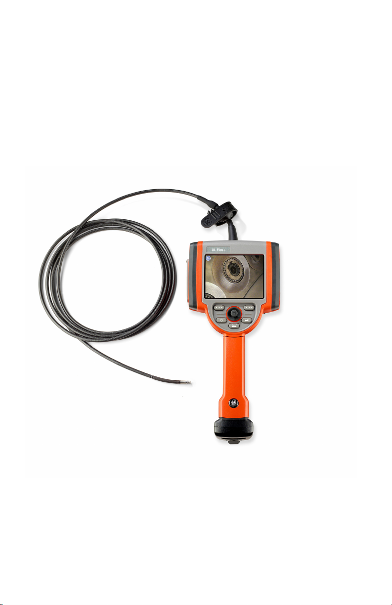
XL Flex / XL Flex +™ VideoProbe
Operating Manual
®
Page 2

Table of Contents
Chapter 1: Introlduction .........................................................5
About this Manual ....................................................................5
Standard Package .................................................................5
Optional Accessories .............................................................5
Optional Software ..................................................................5
Indicators, and Connectors ....................................................7
Controls .................................................................................8
Chapter 2: Safety Information .............................................10
Symbols and Terms .............................................................10
General Warnings ................................................................10
General Cautions .................................................................11
Battery Warnings .................................................................12
Symboles et termes employés ............................................13
Avertissements généraux ....................................................13
Mentions générales « Attention » ........................................14
Avertissements liés à la batterie ..........................................14
Chapter 3: Getting Started ...................................................16
System Removal .................................................................16
System Power On ................................................................17
System Power O ................................................................18
System Storage ...................................................................18
Mounting Accessories ..........................................................19
Battery .................................................................................20
Battery Charge Level ...........................................................21
Charging Battery ..................................................................21
Keyboard Support ................................................................22
Saving Images and Video ....................................................23
Optical Tips ..........................................................................24
Tip Tool Proper Use (4.0 mm only) ......................................25
Chapter 4: Common Tasks ..................................................26
GO TO Menu ..........................................................................26
Live Main Menu ......................................................................34
Input Method Editors ..............................................................45
Chapter 5: Operation ............................................................52
Battery Icon ............................................................................53
Date / Time .............................................................................54
Text Color ...............................................................................56
Temp Icon .............................................................................. 57
Stereo Tip Utilities...................................................................60
Units ......................................................................................62
Accuracy Index ......................................................................63
User Prompts..........................................................................64
Save Location ........................................................................66
MPEG Quality .........................................................................67
2 XL Vu™ VideoProbe
®
Page 3

Table of Contents
MIC .........................................................................................68
SETUP. ...................................................................................69
Save Location .........................................................................70
JPEG Quality ..........................................................................72
Playback Volume ...................................................................74
System Info.............................................................................79
Power Management ...............................................................80
Capturing Images and Video ..................................................82
Articulation Home ...................................................................83
Freeze Frame .........................................................................84
Still Image Capture and Playback ..........................................87
Video Recording and Playback ..............................................87
File Manager...........................................................................88
Video Playback Menu .............................................................90
Copying Files/Folders .............................................................91
Deleting Files/Folders .............................................................92
Creating a Folder ....................................................................93
Renaming Files/Folder ...........................................................94
Chapter 6: Measurement......................................................95
About Measurement ...............................................................95
Capturing Measurement Images for Re-Measurement ..........96
Stereo measurement images can be saved allowing the user to
Measurement Procedure ........................................................96
Accuracy Index .......................................................................96
StereoProbe Measurement ....................................................97
Comparison Measurement ....................................................98
Chapter 7: Maintenance ..................................................... 111
Inspecting and Cleaning the System .................................... 111
Cleaning Optical Tips............................................................ 111
Troubleshooting Measurement ............................................. 112
Service..................................................................................113
Chapter 8: Technical Specications ................................. 114
Product Specications: ......................................................... 114
Appendix .............................................................................119
A. Optical Tip Table ...............................................................119
B. Chemical Compatibility.....................................................123
C. Warranty ..........................................................................124
D. Verifying Measurement Tips.............................................125
E. Environmental Compliance .............................................126
F. Agency Certications ........................................................127
G.Creating a Personalized Logo File....................................129
I. Restoring Factory Defaults ................................................131
XL Vu™ VideoProbe® 3
Page 4

Introduction
This instruction handbook is for use by the owner of the Remote Visual Inspection equipment
and their personnel. GE Inspection Technologies remains the owner of the copyright on this
instruction handbook. No part of this work covered by the copyrights herein may be translated,
reproduced, stored in information retrieval systems, or transmitted, in any form or by any means
graphic, electronic, or mechanical, including photocopying, recording, taping, or otherwise
without the prior written permission of the publishers.Individual reproductions are allowed
for business purposes only with the prior written consent of GE Inspection Technologies.
Should you have any questions concerning clarication of problems in connection with
application, use, operation, specication of your Remote Visual Inspection equipment,
please contact the following:
Technical Support Contact Information
Global Phone: 1-866-243-2638
Email: RemoteSupport@GE.com
NOTE: Contact information is subject to change. Please visit the GE Inspection
Technologies website for the latest contact information.
NOTE: The terms XL Flex and XL Flex+, within this document, are used
interchangeably and with the intent that both are applicable unless otherwise
specied.
This equipment is manufactured under one or more of the following
US patents:
• 4,989,581 • 4,980,769 • 5,070,401 • 5,373,317
• 5,435,296 • 5,754,313 • 6,097,848 • 6,468,201
• 6,590,470 • 6,959,432 • 7,170,677 • 7,262,797
• 7,564,626
4 XL Flex+™ VideoProbe
®
Page 5

Introduction
About this Manual
This manual and the related equipment is intended for visual inspection
technicians with a basic understanding of inspection principles and
practices, and who are familiar with basic computer operations, but who
may not have experience with a video borescope system.
The manual contains complete setup, operating, and maintenance
instructions for the video borescope system. The manual also provides
a product overview, step-by-step procedures, and reference information.
To ensure operator safety, please read and understand this manual prior
to using the system.
For additional assistance, go to www.ge-mcs.com for a complete listing
of contact information.
Standard Package
XL Flex Documentation Thumbdrive
2-hour Li-Ion Battery Quickstart Card
Wheeled- Storage Case Optical Tip Storage Case
AC Adapter/Battery Charger Inspection Manager
Optional Accessories
Spare 4 hour battery Headset
VGA Video Cable Belt Clip
Insertion Tube Gripper Keyboard
Insertion Tube Rigidizer Optical Tips
12V DC Power Adaptor Measurement Optical Tips
Handset Holder Mini-Magic Clamp Kit
Soft Case Magic Arm Kit
Neck Strap Handset Mounting Hook
Sun Visor
Optional Software
Menu Directed Inspection (MDI)
Stereo Measurement
XL Flex+™ VideoProbe®
5
Page 6
Introduction
XL Flex
MEASUREMENT SETUP
STEREO TIP UTILITIES
UNITS
ACCURACY INDEX
USER PROMPTS
BACK DONE
6 XL Flex+™ VideoProbe
®
Page 7

Indicators, and Connectors
1 LCD Screen
2 USB2 Port
3 Integrated 2.5 mm Headset/Microphone Jack
4 VGA output
5 Controls
6 2-hour Lithium Ion Battery
7 Battery Removal Tab
8 Battery Charge Indicator
9 AC Adaptor Input
10 USB1 Bay
11 Insertion Tube Strap
12 Insertion Tube
Introduction
XL Flex+™ VideoProbe®
7
Page 8
Introduction
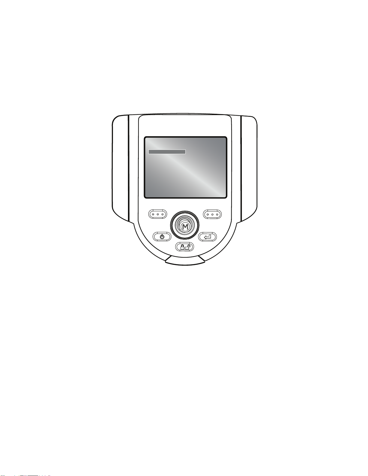
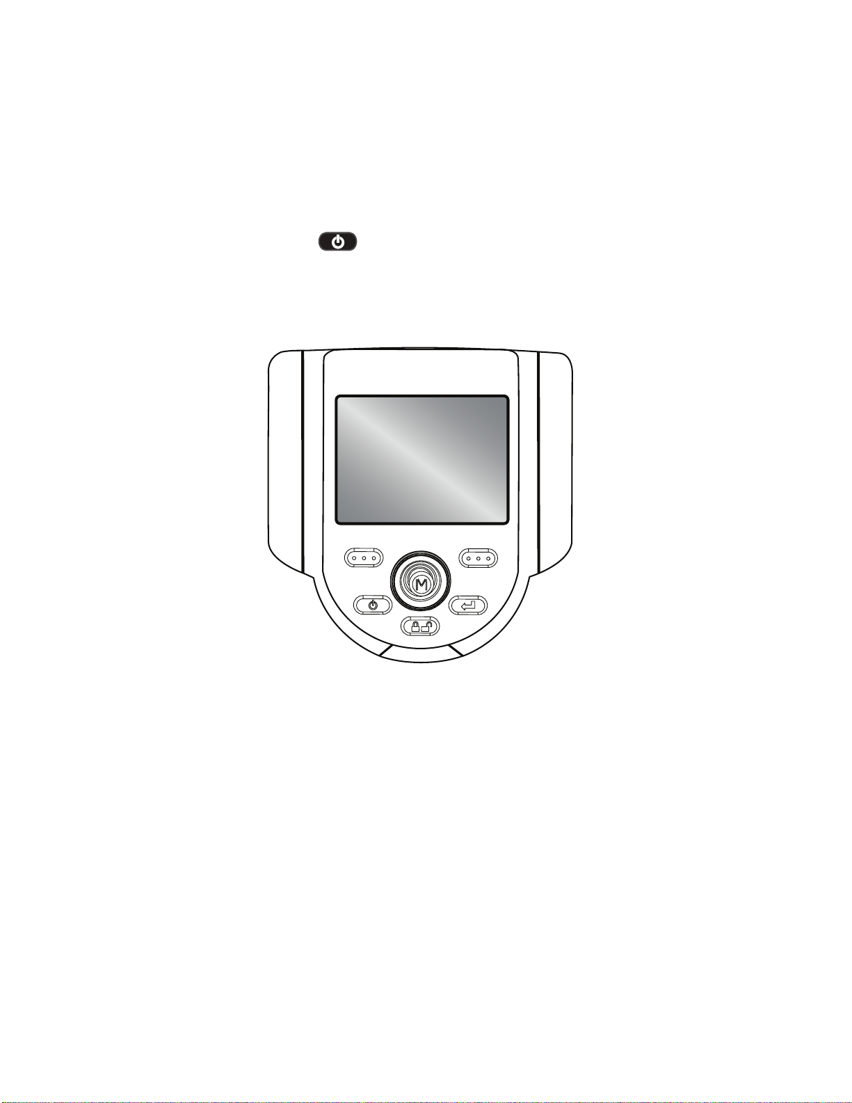
Controls
The following buttons control basic and advanced operation of the XL Flex+
VideoProbe.
XL Flex
XL Vu
1
2
6
3
4
8 XL Flex+™ VideoProbe
5
®
Page 9
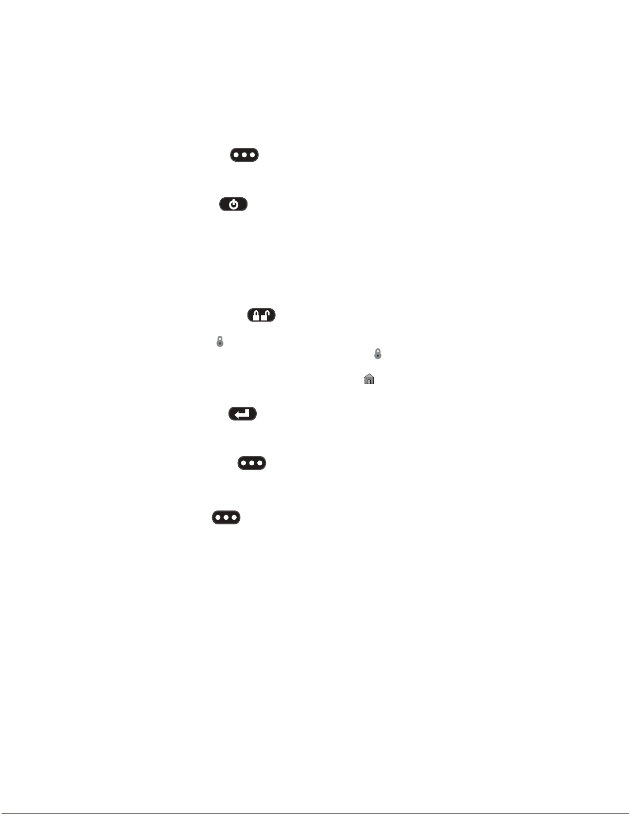
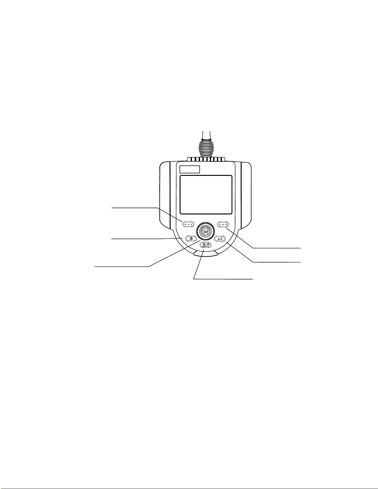
Introduction
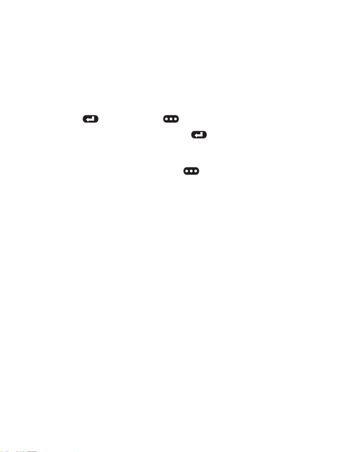
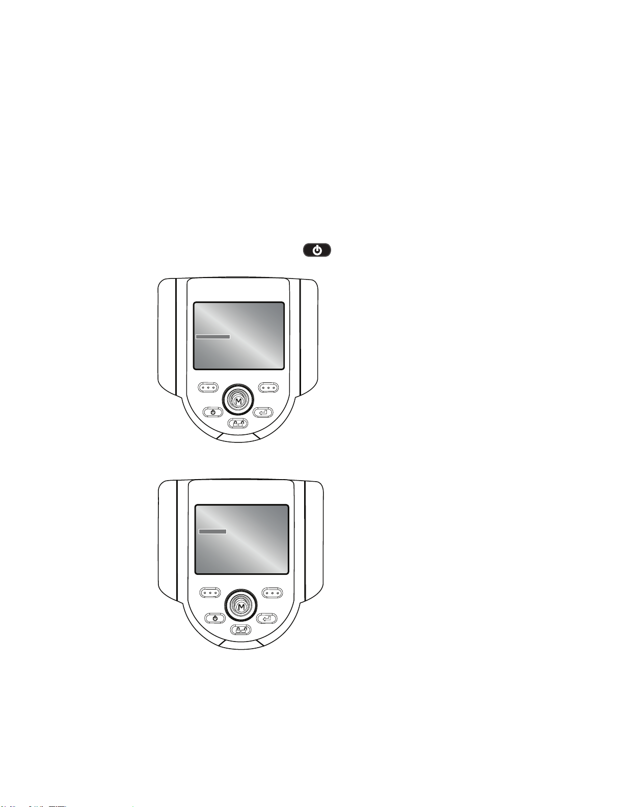
1 Left Soft Key
Activates screen command listed on system LCD. This key will most
frequently return the user BACK one screen.
2 Power/Exit
Turns system power on/o. Also used to exit menus, return to live/frozen
video and disable image control features.
3 Joystick
Controls articulation. Press to activate the Live Main Menu, Recalled
Image Menu, and Freeze Frame Menu. Push the joystick left/right/up/
down to navigate menus and sub-menus.
4 Steering Control
Press and release to keep bending neck locked in place after the joystick
is released. A lock will appear on the LCD when enabled. Press and
release again to unlock the steering control. The lock will disappear
from LCD when disabled. Also, press and hold to engage HOME
function to straighten bending neck. A blinking Home icon will appear
on the LCD when enabled. This icon will disappear when nished.
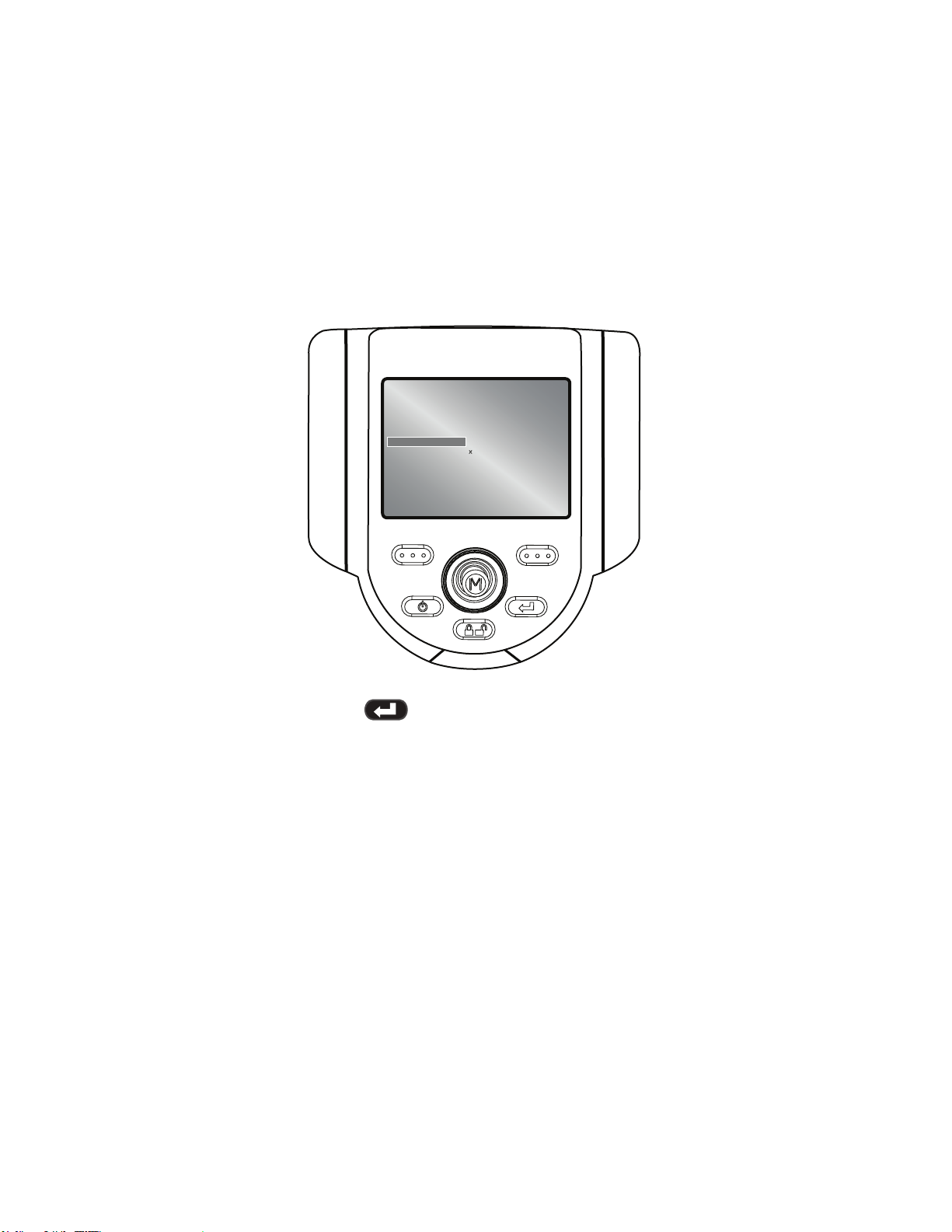
5 Freeze/Enter
Freezes the image on-screen. Also acts as enter key for selecting
options.
6 Right Soft Key
Activates screen command listed on system LCD. This key will most
frequently serve to SELECT active menu choices. This key will also
provide an alternative method to access the LIVE MAIN MENU. Press
and hold the right soft key labeled GOTO for ~ 3 seconds.
XL Flex+™ VideoProbe®
9
Page 10
Safety Information
Note: Before using or servicing the system, read and understand the
following safety information.
Symbols and Terms
The following symbols appear on the product:
See accompanying documentation.
General Warnings
The following warning statements apply to use of the system in general.
Warning statements that apply specically to particular procedures
appear in the corresponding sections of the manual.
Do not allow the conductive insertion tube, system or
its working tools to come in direct contact with any voltage
or current source. Prevent all contact with live electrical
conductors or terminals. Damage to the equipment and/or
electrical shock to the operator may result.
Do not use this system in explosive environments
USE PROPERLY. Using any piece of this equipment
in a manner not specied by the manufacturer may impair the
product’s ability to protect the user from harm.
10 XL Flex+™ VideoProbe
®
Page 11

Safety Information
General Cautions
The following caution statements apply to use of the XL Flex device
in general. Caution statements that apply specically to particular
procedures appear in the corresponding sections of the manual.
HANDLE PROBE CAREFULLY. Keep the insertion tube away from sharp
objects that might penetrate its outer sheath. Keep the whole insertion
tube as straight as possible during operation; loops or bends anywhere
in the tube decrease its ability to steer the probe tip. Avoid bending the
insertion tube sharply.
Note: Always use the Home button to straighten the bending neck
before withdrawing insertion tube from inspection area or putting probe
away. Never pull, twist, or straighten the bending neck by hand; internal
damage may result. At the rst sign of damage, return the probe for
repair.
Certain substances may damage the probe. For a list of substances that
are safe for the probe, see “Chemical Compatibility” in the Appendix.
XL Flex+™ VideoProbe® 11
Page 12

Safety Information
Battery Warnings
Only use the battery (XLGOABATTA or XLGOABATTB) and power
supply (XLGOACHGR or XLGOAAUTOC) specied for use with the XL
Flex+ system.
Before use, thoroughly review the instructions in this manual for the battery and battery charger to fully understand the information contained in
them, and observe the instructions during use.
WARNING
• Do not place the battery in re or exceed the battery operating
temperature.
• Do not pierce the battery with nails, strike the battery with a hammer,
step on the battery, or otherwise subject it to strong impacts or
shocks.
• Do not expose the battery to water or salt water, or allow the battery
to get wet.
• Do not disassemble or modify the battery.
Battery Communication Error: If the XL Flex+ shows this error
message on the display, please contact your nearest customer support
center.
Using the battery outside its recommended operating range will result
in degradation of the performance and service life. When storing the
battery, be sure to remove it from the base unit.
Recommended temperature range for Li-ion battery operation.
Discharge (when using the instrument): : -20˚ C to 46˚ C
Recharging : 0˚ C to 40˚ C
Storage : -25˚ C to +60˚ C
12 XL Flex+™ VideoProbe
®
Page 13
Safety Information
Remarque : avant l’utilisation ou l’entretien du système, vous devez lire
et comprendre les informations de sécurité qui suivent.
Symboles et termes employés
Les symboles suivants sont apposés sur le produit :
Voir la documentation jointe.
Avertissements généraux
Les avertissements suivants s’appliquent à l’utilisation du système
en général. Les avertissements qui s’appliquent spéciquement
à des procédures particulières sont indiqués dans les sections
correspondantes de ce manuel.
Le système XL Flex+ et les outils de travail qui
l’accompagnent ne doivent jamais entrer en contact direct
avec une source de tension ou de courant. Évitez tout contact
avec des conducteurs ou des bornes électriques sous tension.
L’équipement risquerait d’être endommagé, ou l’opérateur de
subir un choc électrique.
N’utilisez pas ce système dans un environnement à
risque d’explosion.
UTILISER CORRECTEMENT. Si un élément de cet
équipement est utilisé d’une manière non indiquée par le
fabricant, l’utilisateur peut ne plus être protégé des risques de
blessure.
XL Flex+™ VideoProbe® 13
Page 14

Safety Information
Mentions générales « Attention »
Les mentions « Attention » qui suivent s’appliquent à l’utilisation
de l’appareil XL Flex+ en général. Les mentions « Attention » qui
s’appliquent spéciquement à des procédures particulières sont
indiquées dans les sections correspondantes du manuel.
MANIPULER LA SONDE AVEC PRÉCAUTION. Maintenez la gaine
de la sonde à l’écart d’objets pointus ou tranchants qui risqueraient
de traverser son fourreau. Maintenez toute la gaine aussi droite que
possible pendant l’utilisation : en cas de boucle ou de courbure, il est
plus dicile de piloter le bout de la sonde. Évitez de trop courber la
gaine.
Remarque : utilisez toujours le bouton de rangement pour redresser
le béquillage avant de rétracter la gaine de la zone d’inspection ou
de ranger la sonde. Ne manipulez jamais le béquillage à la main pour
le tirer, le courber ou le redresser : vous risqueriez de l’endommager
à l’intérieur. Envoyez la sonde en réparation au premier signe
d’endommagement.
Certaines substances risquent d’endommager la sonde. Pour consulter
la liste des substances sans danger pour la sonde, voir Compatibilité
Chimique en annexe.
Avertissements liés à la batterie
Utilisez uniquement la batterie (XLGOABATTA or XLGOABATTB) et
l’alimentation (XLGOACHGR or XLGOAAUTOC) spéciées pour être
utilisées avec le système XL Flex+.
Avant utilisation, lisez attentivement les instructions contenues dans
ce manuel relatives à la batterie et au chargeur de batterie pour bien
les comprendre, et respectez ces instructions pendant l’utilisation de
l’appareil.
AVERTISSEMENT
• Ne jetez pas la batterie au feu et ne dépassez pas sa température
de fonctionnement.
• Ne percez pas la batterie avec des clous, ne la frappez pas avec
un marteau, ne marchez pas dessus et ne la soumettez pas à des
14 XL Flex+™ VideoProbe
®
Page 15

Safety Information
impacts ou des chocs violents.
• N’exposez pas la batterie à l’eau douce ou salée, et évitez de la
mouiller.
• Ne désassemblez pas la batterie et ne la modiez pas.
Erreur de communication de la batterie. Veuillez contacter le
Service clientèle au numéro +1 866 243 2638.
L’utilisation de la batterie en dehors de la plage de fonctionnement
recommandée entraînerait une dégradation de ses performances et de
sa longévité. Lorsque vous stockez la batterie, veillez à la retirer de sa
base.
Plage de température recommandée pour le fonctionnement de la
batterie Lithium-Ion.
Décharge (à l’utilisation de l’appareil) : -20˚C à +46˚CRecharge , 0˚C à
+40˚CStockage, -25˚C à +60˚C
XL Flex+™ VideoProbe® 15
Page 16
Getting Started
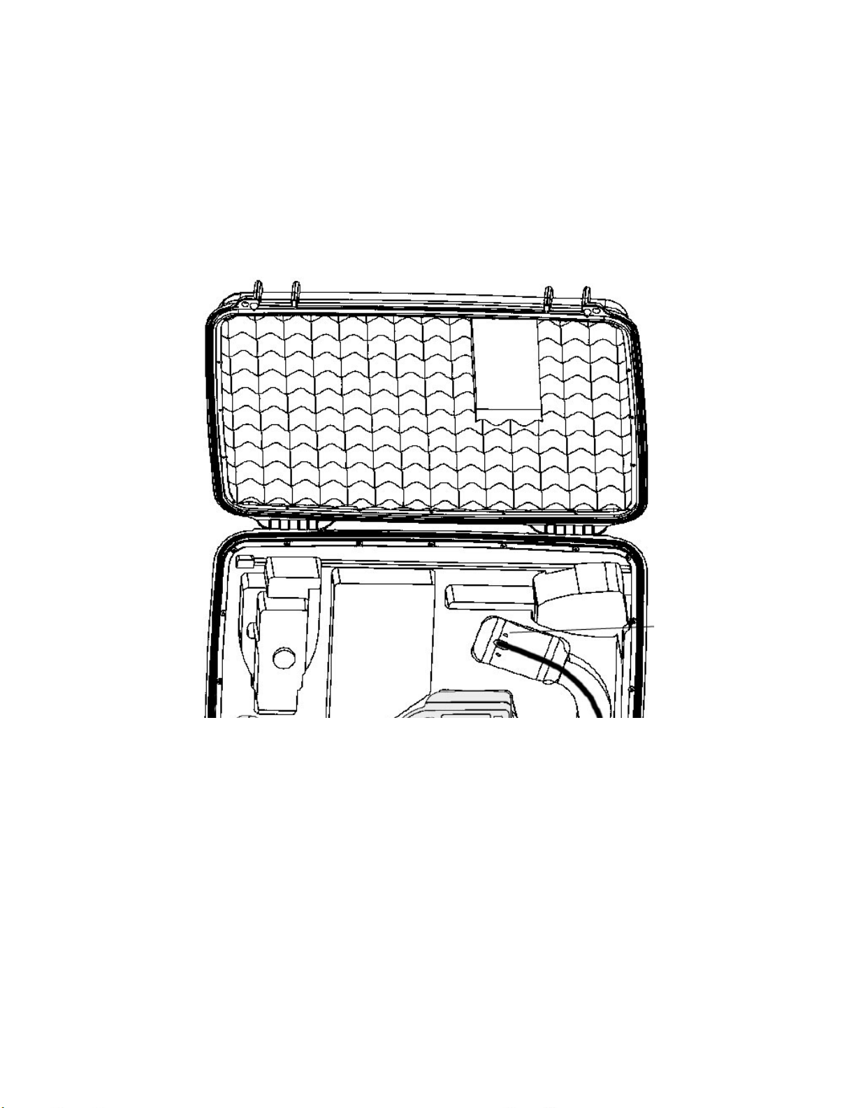
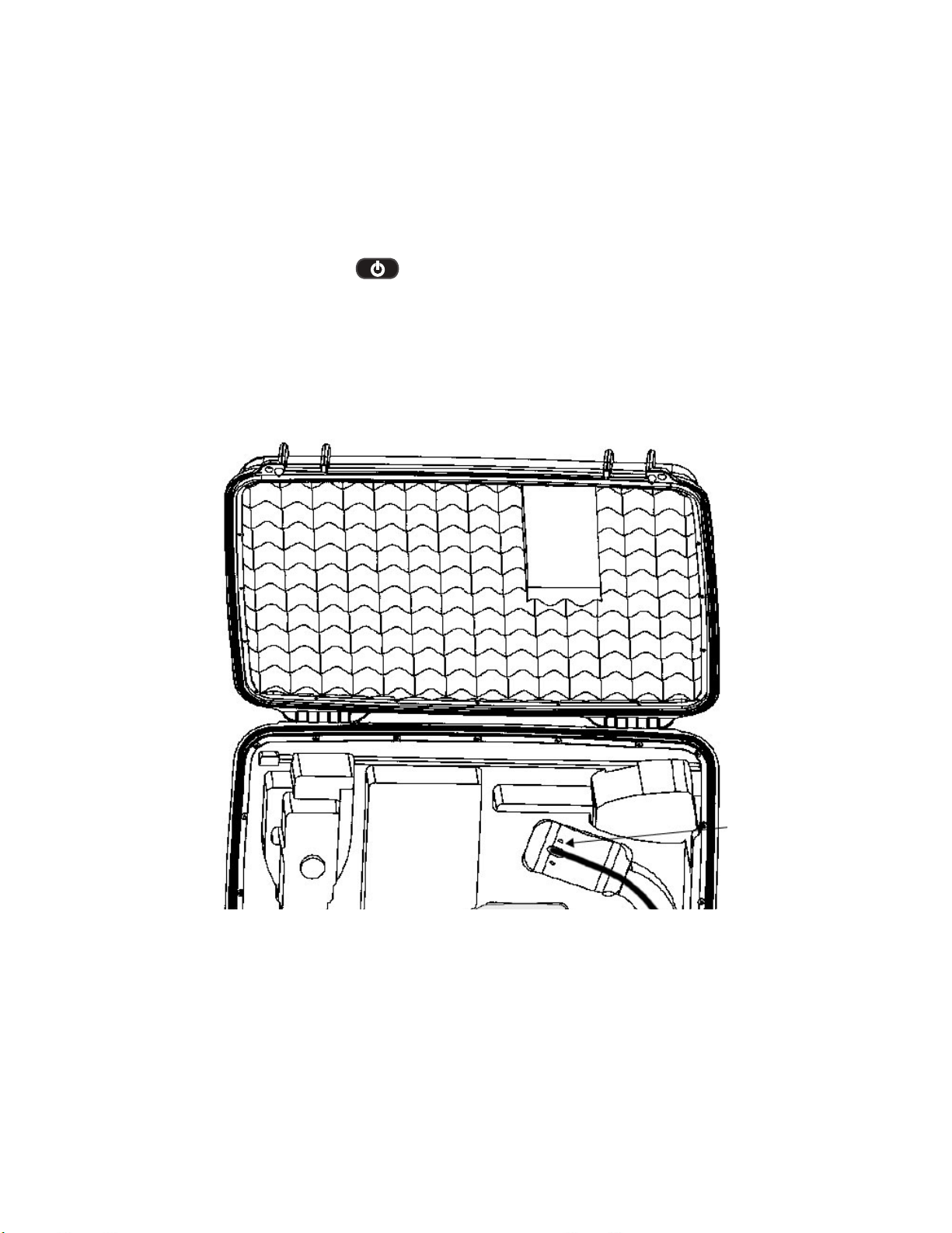
System Removal
Gently remove the insertion tube from the internal storage reel and lift
the handset from the storage case.
16 XL Flex+™ VideoProbe
®
Page 17
Getting Started
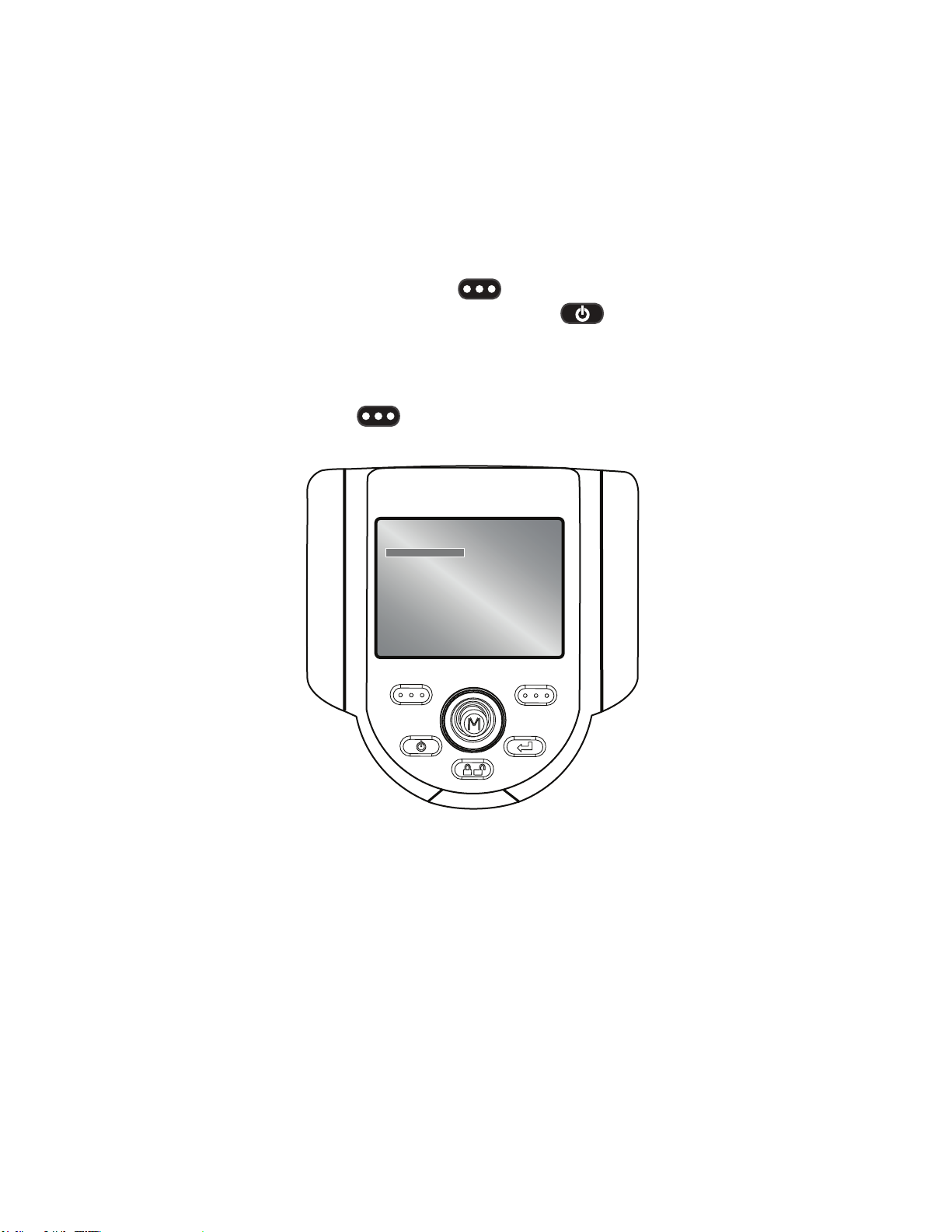
System Power On
Press and hold the Power/Exit key until unit turns on. The buttons
and Liquid Crystal Display (LCD) will light and begin the power-up
sequence. After approximately 30 seconds, select the desired language.
The system screen will display live video and screen prompts. The
system is now ready for use.
XL Flex
RECORD GOTO
Note: All batteries are shipped with a partial charge. Batteries should be
fully charged prior to use.
XL Flex+™ VideoProbe® 17
Page 18
Getting Started
System Power O
Press and hold the Power/Exit key until the “SYSTEM SHUTTING
DOWN” message appears. Key illumination and LED probe lights will go
out when system is completely powered down.
System Storage
Place the tip of the insertion tube into the orange funnel and gently feed
into storage reel. Place the XL Flex+ handset into the designated foam
cutout. LCD screen should face up.
18 XL Flex+™ VideoProbe
®
Page 19
Getting Started
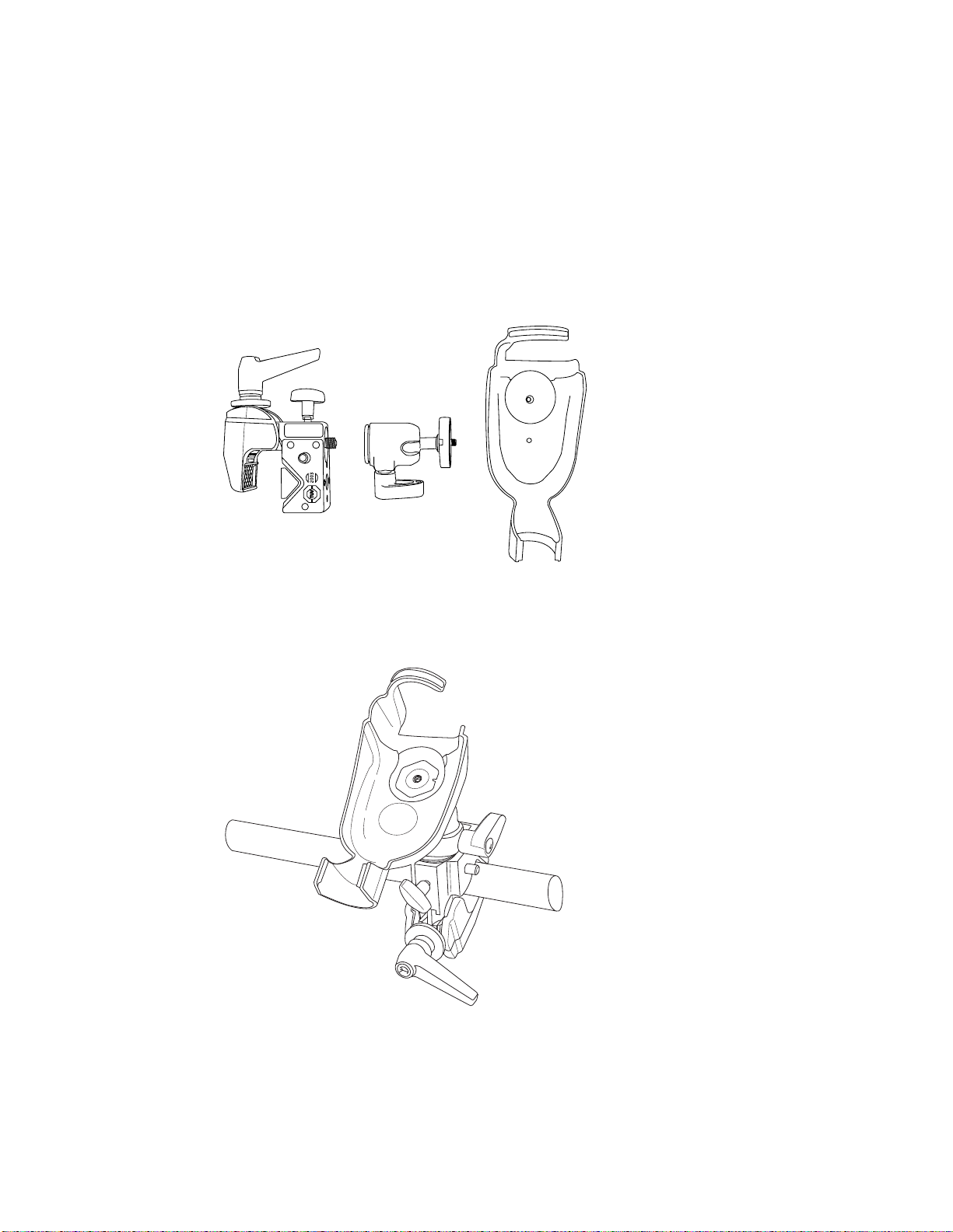
Mounting Accessories
Assemble the optional mounting accessories by screwing together the
mini magic clamp, swivel ball, and handset holder.
Secure the XL Flex+ mini magic clamp and place the XL Flex+ system in
the handset holder.
XL Flex+™ VideoProbe® 19
Page 20
Getting Started
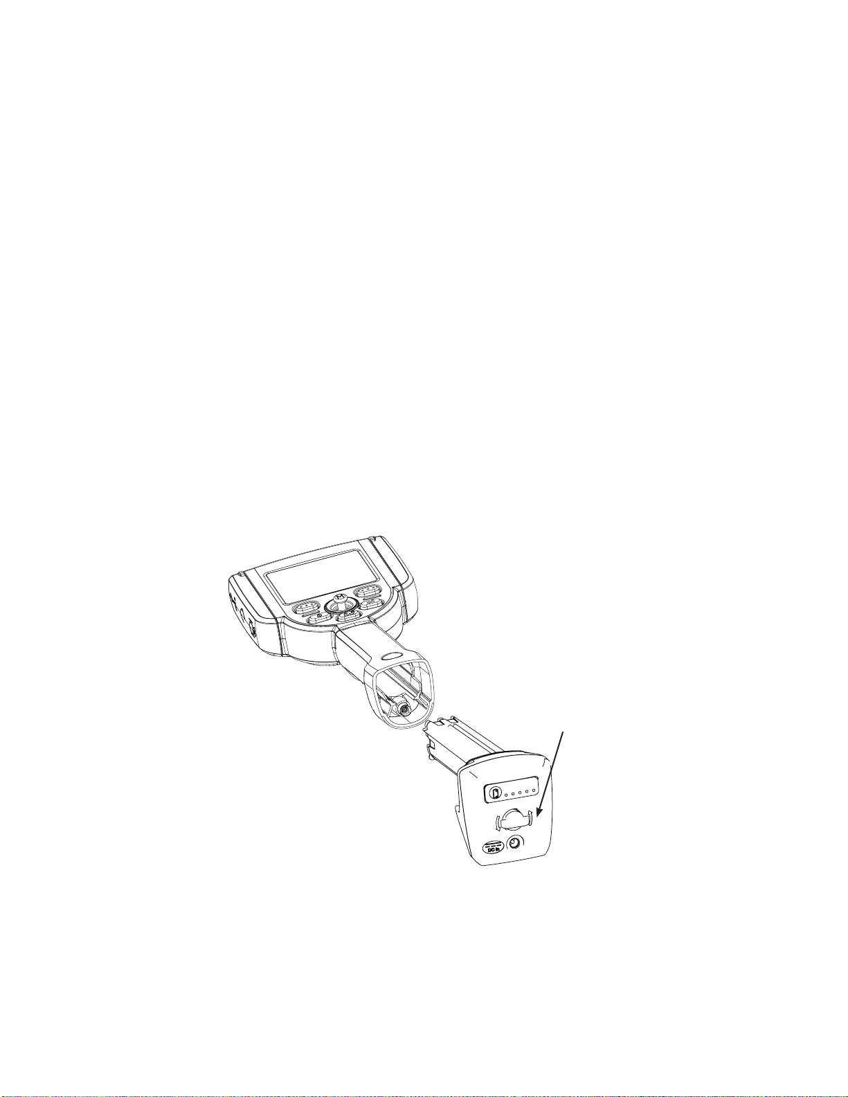
Battery
Installing Battery
Insert the battery into the handset. The battery is installed properly when
the latching mechanism is engaged.
Note: Do not force the battery into the handset, as damage may occur.
The battery is keyed and may only be installed in the proper orientation.
Removing Battery
For batteries with the removal tab, using your hand, turn the tab counterclockwise to release the battery.
Note: Do not use a tool to remove the battery.
For batteries with the locking screw, using a standard screwdriver or
coin, turn the locking screw counterclockwise and release the battery.
Note: Do not remove battery while system is operating.
Battery removal tab
20 XL Flex+™ VideoProbe
®
Page 21
Getting Started
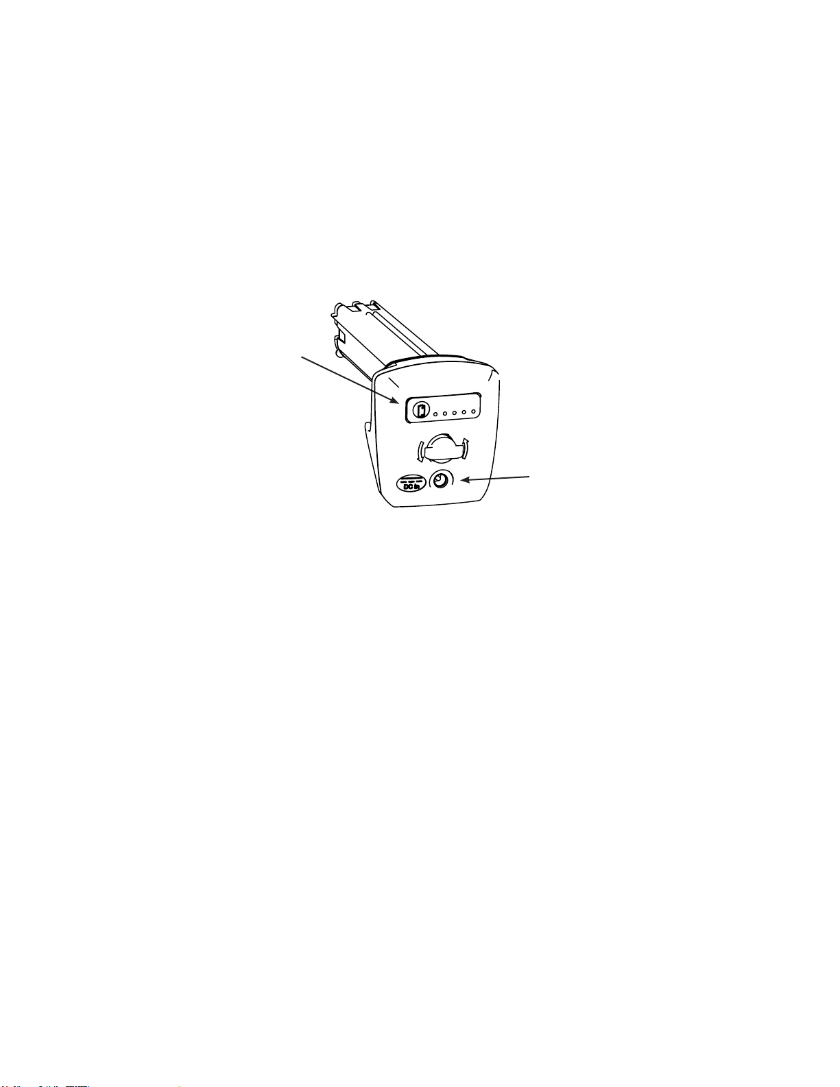
Battery Charge Level
Check the battery charge by pressing the battery symbol on the front
of the battery. Each light represents approximately 20% of the battery
charge capacity.
Charge Indicator LED’s
DC Battery Charging Jack
Charging Battery
Plug the included AC to DC power adaptor into a suitable AC power
source and connect the DC output of the battery charger into the XL
Flex+ battery. The LED battery lights will illuminate according to the
amount of charge attained. The system may operate while charging.
The battery may also be charged while disconnected from the system.
Note: When the battery is fully charged, the LED battery lights will turn o.
Note: Battery run time approximately equals battery charge time;
therefore, a four hour battery will take approximately four hours to
charge.
XL Flex+™ VideoProbe® 21
Page 22

Getting Started
Keyboard Support
To use an external, USB keyboard, plug the approved device into one of
the two USB ports.
For a list of approved keyboards, contact your sales representative or
customer support.
The function keys on the keyboard act as the keys on the XL Flex+:
F1: Menu Function on Joystick
F2: Left Soft Key
F3: Power/Exit Key
F4: Steer & Stay Key
F5: Enter Key
F6: Right Soft Key
Note: Keyboards only support the top level functions and will not support
the press and hold functions such as video recording.
22 XL Flex+™ VideoProbe
®
Page 23
Getting Started
Saving Images and Video
Still Images
To capture a still image, compose the picture and press and release
Freeze/Enter. Press the right soft key with SAVE on the
LCD above to save to the default location.
Alternately, from live video, press and hold Freeze/Enter to quick-
save.
Video
To record live video, press and hold the left soft key labeled
RECORD on the LCD above. A red record symbol will appear in the
upper right hand corner. When the video is stopped, it will automatically
save to the default location.
Note: See measurement section for instructions on saving images for
future remeasurement on the XL Flex+ or a PC.
XL Flex+™ VideoProbe® 23
Page 24

Getting Started
Optical Tips
Optical tips are attached to the camera head using a double thread. This
prevents unintended departures of optical tips from the probe. Each
optical tip provides a unique depth of eld (DOF), eld of view (FOV) and
direction of view (DOV). A complete list of available tips is provided in
the Appendix.
Optical Tip Removal
1. Grasp the head of the probe with one hand and gently loosen the tip
counterclockwise with the other hand. The tip has cleared the rst
set of threads when it spins freely.
2. Gently pull the tip away from the probe and continue loosening
counterclockwise until the tip is free from the second set of threads.
Optical Tip Installation
1. Ensure the optical tip is clean. Clean if necessary (See Cleaning
Optical Tips).
2. Grasp the head of the probe with one hand and gently turn the tip
clockwise with the other hand. The tip has cleared the rst set of
threads when it spins freely and then seats with gentle force applied.
3. Gently push the tip onto the probe and continue turning clockwise on
the second set of threads until the tip is attached nger tight. Do not
over tighten. Pull gently on the tip to ensure proper attachment to
the probe.
NOTE: Never use tools or excessive force to install or remove an
optical tip.
24 XL Flex+™ VideoProbe
®
Page 25

Getting Started
Tip Tool Proper Use (4.0 mm only)
Removing Tips
1. Apply empty tip tool to probe head.
2. Apply pressure while turning in the counter-clockwise position.
3. When tip tool spins freely, gently pull up while twisting in the
counter-clockwise position to release the second set of threads.
4. Remove tip tool and tip will be within.
Applying Tips
1. Apply tip tool containing appropriate tip to probe head.
2. Apply pressure while turning in the clockwise position.
3. When tip tool spins freely, gently push down while twisting in the
clockwise position to engage the second set of threads.
4. Pull gently on tip tool to ensure proper attachment.
5. Remove tip tool and tip will be attached to probe head.
NOTE: Never use excessive force to install or remove an optical tip.
XL Flex+™ VideoProbe® 25
Page 26
Common Tasks
GO TO Menu
Many common operating tasks are available in the GOTO menu. This
menu is available by pressing the right soft key labeled GOTO
during live video mode. To exit any menu, press Power/Exit.
GO TO > File Manager
To enter the le manager, navigate to FILE MANAGER with the joystick
and select with the right soft key labeled SELECT.
XL Flex
GO TO MENU
FILE MANAGER
EJECT HARDWARE
ZOOM LEVEL
LIGHT OUTPUT
LONG EXPOSURE
INVERSE +
INVERT
ANNOTATIONS
BACK SELECT
26 XL Flex+ VideoProbe
®
Page 27
Common Tasks
GO TO > Eject Drive
To eject USB thumb drives before removal, use the joystick to navigate
to the right of EJECT HARDWARE and select the appropriate drive using
the right soft key labeled SELECT.
Note: Always use EJECT HARDWARE before removing a USB thumb
drive to prevent loss of data.
XL Flex
GO TO MENU
FILE MANAGER
EJECT DRIVE
ZOOM LEVEL
LIGHT OUTPUT
LONG EXPOSURE
INVERSE +
INVERT
ANNOTATIONS
BACK SELECT
USB1
USB2
XL Flex+™ VideoProbe® 27
Page 28
Common Tasks
GO TO > Zoom Level
An image can be zoomed from 1 (normal view) to 5 (5 times zoomed).
Navigate to the right of ZOOM LEVEL and use the joystick to adjust the
zoom level. Zoom can be turned o in live video mode by pressing
Power/Exit.
XL Flex
GO TO MENU
FILE MANAGER
EJECT HARDWARE
ZOOM LEVEL
LIGHT OUTPUT
LONG EXPOSURE
INVERSE +
INVERT
ANNOTATIONS
BACK SELECT
5
1
28 XL Flex+ VideoProbe
®
Page 29
Common Tasks
GO TO > Light Output
To turn the camera light source On or O, navigate to the right of LIGHT
OUTPUT and select ON or OFF.
XL Flex
GO TO MENU
FILE MANAGER
EJECT HARDWARE
ZOOM LEVEL
LIGHT OUTPUT
LONG EXPOSURE
INVERSE +
INVERT
ANNOTATIONS
BACK SELECT
ON
OFF
Note: Pressing the Freeze Frame key is a convenient way to
temporarily turn o the light output and is ideal for changing optical tips
and conserving battery charge.
XL Flex+™ VideoProbe® 29
Page 30
Common Tasks
GO TO > Long Exposure
The XL Flex+ system can brighten the image by varying the exposure
time. Keep the probe tip as still as possible when capturing an image
with long exposure to minimize the risk of blurring.
Select LONG EXPOSURE to choose manual exposure, automatic long
exposure, or to turn long exposure o. Long Exposure may be turned o
in live video mode by pressing the Power/Exit key.
XL Flex
GO TO MENU
FILE MANAGER
EJECT HARDWARE
ZOOM LEVEL
LIGHT OUTPUT
LONG EXPOSURE
INVERSE +
INVERT
ANNOTATIONS
BACK SELECT
After selecting Long Exposure, the following options will be available:
XL Flex
LONG EXPOSURE
MANUAL
AUTO
X OFF
BACK SELECT
30 XL Flex+ VideoProbe
®
Page 31

Common Tasks
GO TO > Inverse +
Inverse + reverses the brightness similar to a photographic negative. It
enhances the image contrast, making subtle details more visible. Inverse
+ may be turned o in live video mode by pressing the Power/Exit
key.
To activate or deactivate, navigate to INVERSE + and choose ON or
OFF.
XL Flex
GO TO MENU
FILE MANAGER
EJECT HARDWARE
ZOOM LEVEL
LIGHT OUTPUT
LONG EXPOSURE
INVERSE +
INVERT
ANNOTATIONS
BACK SELECT
ON
OFF
XL Flex+™ VideoProbe® 31
Page 32

Common Tasks
GO TO > Invert
The invert function ips an image horizontally. To activate or deactivate,
navigate to INVERT and choose ON or OFF. Invert may be turned o in
live video mode by pressing the Power/Exit key.
XL Flex
GO TO MENU
FILE MANAGER
EJECT HARDWARE
ZOOM LEVEL
LIGHT OUTPUT
LONG EXPOSURE
INVERSE +
INVERT
ANNOTATIONS
BACK SELECT
ON
OFF
Note: Invert is typically used while a side view tip is installed in order to
compensate for the inversion caused by this tip.
32 XL Flex+ VideoProbe
®
Page 33

Common Tasks
GO TO > Annotations
When Annotations have already been added to the image, user can
quickly remove them by choosing ANNOTATIONS > DELETE ALL.
XL Flex
GO TO MENU
FILE MANAGER
EJECT HARDWARE
ZOOM LEVEL
LIGHT OUTPUT
LONG EXPOSURE
INVERSE +
INVERT
ANNOTATIONS
BACK SELECT
DELETE ALL
XL Flex+™ VideoProbe® 33
Page 34

Common Tasks
Live Main Menu
To activate the LIVE MAIN MENU, press and release the joystick. To exit
any menu, press Power/Exit.
An alternative method to access the LIVE MAIN MENU is a press and
hold of the right soft key labeled GOTO for ~3 seconds.
Live Main Menu > Light Output
To turn the LED optical light on/o, use the joystick to choose LIGHT
OUTPUT and select ON or OFF.
XL Flex
LIVE MAIN MENU
LIGHT OUTPUT
IMAGE CONTROL
ANNOTATION
EJECT HARDWARE
SETUP
FILE MANAGER
BACK SELECT
ON
OFF
Note: Pressing the Freeze Frame key is a convenient way to
temporarily turn o the light output and is ideal for changing optical tips
and conserving battery charge.
34 XL Flex+ VideoProbe
®
Page 35

Common Tasks
Live Main Menu > Image Control
From the LIVE MAIN MENU, select IMAGE CONTROL. The changes
made to the Image Controls take eect immediately.
XL Flex
LIVE MAIN MENU
LIGHT OUTPUT
IMAGE CONTROL
ANNOTATION
EJECT HARDWARE
SETUP
FILE MANAGER
BACK SELECT
The following options are then available:
• Image Brightness
• Zoom Level
• Long Exposure
• Split Screen
• Single View
• Inverse +
• Invert
Note: By pressing the power/exit key twice, any image control
features will be turned o and returned to factory default settings.
XL Flex+™ VideoProbe® 35
Page 36

Common Tasks
Live Main Menu > Image Control > Image Brightness
Navigate to IMAGE BRIGHTNESS from the IMAGE CONTROL Menu
and use the joystick to adjust the image brightness.
XL Flex
IMAGE CONTROL
IMAGE BRIGHTNESS
ZOOM LEVEL
LONG EXPOSURE
SPLIT SCREEN
SINGLE VIEW
INVERSE +
INVERT
BACK SELECT
0 100
36 XL Flex+ VideoProbe
®
Page 37

Common Tasks
Live Main Menu > Image Control > Zoom Level
Navigate to ZOOM LEVEL from the IMAGE CONTROL Menu and use
the joystick to adjust the zoom level. Digital zoom levels from 1x to 5x
may be selected.
XL Flex
IMAGE CONTROL
IMAGE BRIGHTNESS
ZOOM LEVEL
LONG EXPOSURE
SPLIT SCREEN
SINGLE VIEW
INVERSE +
INVERT
BACK SELECT
15
XL Flex+™ VideoProbe® 37
Page 38

Common Tasks
Live Main Menu > Image Control > Long Exposure
The XL Flex+ system can brighten the image by varying the exposure
time. Keep the probe tip as still as possible when capturing an image
with long exposure to minimize the risk of blurring.
Select LONG EXPOSURE to choose manual exposure, automatic long
exposure, or to turn long exposure o. Long Exposure may be turned o
in live video mode by pressing the Power/Exit key.
XL Flex
IMAGE CONTROL
IMAGE BRIGHTNESS
ZOOM LEVEL
LONG EXPOSURE
SPLIT SCREEN
SINGLE VIEW
INVERSE +
INVERT
BACK SELECT
After selecting LONG EXPOSURE, the following options will be available:
XL Flex
LONG EXPOSURE
MANUAL
AUTO
X OFF
BACK SELECT
38 XL Flex+ VideoProbe
®
Page 39

Common Tasks
Live Main Menu > Image Control > Split Screen
From a live, frozen, or recalled image, press the joystick to access the
LIVE MAIN MENU, FREEZE FRAME MENU or RECALLED IMAGE
MENU. Navigate to SPLIT SCREEN and press the right soft key
to select. Choose the area of screen to view by moving the joystick left
or right and using the right soft key to select. The left image is
frozen and the right image is live.
XL Flex
IMAGE CONTROL
IMAGE BRIGHTNESS
ZOOM LEVEL
LONG EXPOSURE
SPLIT SCREEN
SINGLE VIEW
INVERSE +
INVERT
BACK SELECT
XL Flex+™ VideoProbe® 39
Page 40

Common Tasks
Live Main Menu > Image Control > Single View
While navigating the probe with a stereo tip attached, single view
temporarily eliminates the second image.
Navigate to SINGLE VIEW from the IMAGE CONTROL MENU and
select ON or OFF. Pressing the Power/Exit key from live video
will disable Single View.
XL Flex
IMAGE CONTROL
IMAGE BRIGHTNESS
ZOOM LEVEL
LONG EXPOSURE
SPLIT SCREEN
SINGLE VIEW
INVERSE +
INVERT
BACK SELECT
ON
OFF
40 XL Flex+ VideoProbe
®
Page 41

Common Tasks
Live Main Menu > Image Control > Inverse +
Inverse + reverses the brightness like a photographic negative. It
enhances the image contrast, making subtle details more visible.
To alter the contrast of an image, select INVERSE + from the IMAGE
CONTROL MENU and select ON or OFF.
XL Flex
IMAGE CONTROL
IMAGE BRIGHTNESS
ZOOM LEVEL
LONG EXPOSURE
SPLIT SCREEN
SINGLE VIEW
INVERSE +
INVERT
BACK SELECT
ON
OFF
XL Flex+™ VideoProbe® 41
Page 42

Common Tasks
Live Main Menu > Image Control > Invert
The invert function ips an image horizontally. To activate or deactivate
Invert, navigate to INVERT from the IMAGE CONTROL MENU and
select ON or OFF.
XL Flex
IMAGE CONTROL
IMAGE BRIGHTNESS
ZOOM LEVEL
LONG EXPOSURE
SPLIT SCREEN
SINGLE VIEW
INVERSE +
INVERT
BACK SELECT
ON
OFF
Note: This feature is most useful when using Sideview Optical Tips.
42 XL Flex+ VideoProbe
®
Page 43

Common Tasks
Live Main Menu > Annotation
Annotating an XL Flex+ image means adding text or arrows to describe
or point out areas of interest: cracks, defects, etc. Annotation may be
used on live, frozen, and recalled images.
To alter the annotation settings, press the joystick to activate the LIVE
MAIN MENU and select ANNOTATION.
XL Flex
LIVE MAIN MENU
LIGHT OUTPUT
IMAGE CONTROL
ANNOTATION
EJECT HARDWARE
SETUP
FILE MANAGER
BACK SELECT
Note: There is a maximum of 3 lines of text/arrows per annotation.
Note: See the Freeze Frame Menu to enable Audio Annotation
XL Flex+™ VideoProbe® 43
Page 44

Common Tasks
Live Main Menu > Annotation > Text
To add, edit, or clear text on a specic image, select TEXT from the
ANNOTATION menu.
XL Flex
ANNOTATION
TEXT
ARROW
PRESET
HIDE ANNOTATION
AUDIO
BACK SELECT
ADD
EDIT
DELETE
DELETE ALL
XL Flex
USE JOYSTICK/ENTER TO ENTER TEXT.
^ < > v ENTER SPACE BACKSPACE
B
C
D
E
F
G
H
I
J
A
O
P
Q
R
N
2
3
4
5
1
,
:
;
?
.
@
#
$
%
~
PRESETS ADD TO PRESETS
BACK DONE
K
S
T
U
V
W
X
6
7
8
9
0
+
!
\
/
^
<
>
&
_
|
(
)
{
L
M
Y
Z
-
=
*
`
‘
“
}
[
]
Note: Maximum number of text annotation characters is 50.
44 XL Flex+ VideoProbe
®
Page 45

Common Tasks
Live Main Menu > Annotation
Input Method Editors
The XL Flex+ supports text entry with advanced input methods for
Simplied Chinese (Pinyin) and Japanese (Hiragana to Katakana/Kanji).
To utilize these input methods the user must have an external keyboard
connected to the VideoProbe. These input methods default as active
when either Chinese or Japanese are selected as the system language.
To return to an on-screen keyboard that does not utilize an input method,
toggle the button that reads “Input Method -/O”
Chinese
The XL Flex+ supports the Pinyin text entry method. For each word or
phrase that you wish to enter, please perform the following:
1. Using the external keyboard, type the Pinyin representation of
the character to be entered.
2. Use the numbers on the external keyboard to select the desired
character from the candidate list.
3. Press the enter key to conrm the selection.
Japanese
The XL Flex+ supports a text entry method that converts Hiragana to
Katakana and Kanji characters. For each word or phrase you wish to
enter, please perform the following:
1. Using the external keyboard, enter the Hiragana that make
up the word being entered.
2. When all of the Hiragana that make up the word is entered,
press the space bar on the external keyboard to get a
candidate list of characters.
3. Use the numbers on the keyboard to select the desired word.
4. Press the enter key to conrm selection.
Note: If the desired word is not shown in the candidate list, press Page
Up / Page Down on the keyboard to cycle through more options.
Note: A maximum of 6 Hiragana may be entered for each word or phrase
for Japanese text entry.
XL Flex+™ VideoProbe® 45
Page 46

Common Tasks
Live Main Menu > Annotation > Arrow
To add, edit or clear arrow on a specic image, select ARROW from the
ANNOTATION menu.
XL Flex
ANNOTATION
TEXT
ARROW
PRESET
HIDE ANNOTATION
AUDIO
BACK SELECT
ADD
EDIT
DELETE
DELETE ALL
Note: Maximum number of arrow annotations is 25.
46 XL Flex+ VideoProbe
®
Page 47

Common Tasks
Live Main Menu > Annotation > Preset
To create, recall or delete a preset annotation that will display throughout
an inspection, choose PRESET from the ANNOTATION menu. To
load or export a le containing presets, choose PRESET from the
ANNOTATION menu.
XL Flex
ANNOTATION
TEXT
ARROW
PRESET
HIDE ANNOTATION
AUDIO
BACK SELECT
CREATE
RECALL
EDIT
DELETE
IMPORT
EXPORT
Note:
• Maximum number of preset annotations is 100
• Preset les must be line-delimited .txt les
• The maximum preset length is calculated by character width
(approximately 28 characters).
XL Flex+™ VideoProbe® 47
Page 48

Common Tasks
Live Main Menu > Annotation > Loading a Preset
To load a le containing multiple presets onto the XL Flex+, a le may be
created on a PC. This le must conform to the following:
• Line-delimited (each preset must be on a separate line)
• File Type - .txt
• Encoding - UTF8
• Recommended Program - Microsoft™ Notepad
At the time of saving the document, select .txt as the le type and UTF-8
as the encoding. See example below.
Loading the File
1. Save the Preset.txt le onto external media(CF Card, USB
ThumbDrive, etc).
2. Insert the external media into XL Flex+.
3. Access the LIVE MAIN MENU by pressing joystick.
4. Select ANNOTATION.
5. Select PRESET > LOAD.
6. Locate the le that you have created.
48 XL Flex+ VideoProbe
®
Page 49

Common Tasks
Live Main Menu > Annotation > Hide Annotation
To hide or unhide an annotation, select HIDE ANNOTATION from the
ANNOTATION menu followed by ON or OFF.
XL Flex
ANNOTATION
TEXT
ARROW
PRESET
HIDE ANNOTATION
AUDIO
BACK SELECT
ON
OFF
XL Flex+™ VideoProbe® 49
Page 50

Common Tasks
Live Main Menu > Eject Hardware
To eject USB thumb drives before removal, use the joystick to navigate
to the right of EJECT HARDWARE and select the appropriate drive using
the right soft key labeled SELECT.
XL Flex
LIVE MAIN MENU
LIGHT OUTPUT
IMAGE CONTROL
ANNOTATION
EJECT HARDWARE
SETUP
FILE MANAGER
BACK SELECT
USB1
USB2
Note: Always use EJECT HARDWARE before removing a USB
thumbdrive to prevent loss of data.
50 XL Flex+ VideoProbe
®
Page 51

Common Tasks
Live Main Menu > Setup
To change default settings, select SETUP. For more information see
SYSTEM SETUP Section in the Operation Chapter.
XL Flex
LIVE MAIN MENU
LIGHT OUTPUT
IMAGE CONTROL
ANNOTATION
EJECT HARDWARE
SETUP
FILE MANAGER
BACK SELECT
XL Flex+™ VideoProbe® 51
Page 52

Operation
Live Main Menu > Setup
The System Setup Menu accesses the default settings. To exit any
menu, press Power/Exit.
Live Main Menu > Setup > Screen/Display Setup
To alter the display setup, press the joystick to activate the LIVE MAIN
MENU. Select SETUP followed by SCREEN/DISPLAY.
XL Flex
SETUP
SCREEN/DISPLAY
MEASUREMENT SETUP
VIDEO RECORD SETUP
STILL IMAGE SETUP
AUDIO PLAYBACK SETUP
STEERING SETUP
LANGUAGE SETUP
SYSTEM TOOLS
BACK SELECT
52 XL Flex+™ VideoProbe
®
Page 53

Operation
Live Main Menu > Setup > Screen/Display >
Battery Icon
To enable and disable the battery icon, select BATTERY ICON followed
by ON or OFF.
XL Flex
SCREEN/DISPLAY
BATTERY ICON
DATE/TIME
LOGO
TEXT COLOR
TEMP ICON
WHITE BALANCE
BACK SELECT
ON
OFF
XL Flex+™ VideoProbe® 53
Page 54

Operation
CK
SELLECTCTCT
Live Main Menu > Setup > Screen/Display >
Date / Time
To enable or disable the date/time stamp, as well as set the date and
time, select DATE/TIME from the SCREEN/DISPLAY menu.
XL Flex
SCREEN/DISPLAY
BATTERY ICON
DATE/TIME
LOGO
TEXT COLOR
TEMP ICON
WHITE BALANCE
ON
OFF
X
SET
BACK SELECT
To change date format between MM/DD/YYYY and DD/MM/YYYY, select
the Month, Day, Year format and move the joystick up or down to select
prefered format. Select OK when finished.
XL Flex
PLEASE ENTER TIME AND DATE
X
XX/XX/XXXX DD/MM/YYYY
00:00 PM 24HR
BACK SELEC T
BA
BACK OK
54 XL Flex+™ VideoProbe
®
Page 55

Operation
Live Main Menu > Setup > Screen/Display > Logo
A logo may be added to the screen. The le name “logo.jpg” must be
used. To load a logo, or to turn a logo on or o, select LOGO from the
SCREEN/DISPLAY menu and select the desired option.
XL Flex
SCREEN/DISPLAY
BATTERY ICON
DATE/TIME
LOGO
TEXT COLOR
TEMP ICON
WHITE BALANCE
BACK SELECT
ON
OFF
LOAD
Note: See Appendix G for details on creating a logo le.
XL Flex+™ VideoProbe® 55
Page 56

Operation
Live Main Menu > Setup > Screen/Display >
Text Color
The most legible text color will vary with the coloring and brightness of
the image. To change the color of the text displayed over images, select
TEXT COLOR followed by GREEN, BLACK, or WHITE.
XL Flex
SCREEN/DISPLAY
BATTERY ICON
DATE/TIME
LOGO
TEXT COLOR
TEMP ICON
WHITE BALANCE
BACK SELECT
GREEN
BLACK
WHITE
56 XL Flex+™ VideoProbe
®
Page 57

Operation
Live Main Menu > Setup > Screen/Display >
Temp Icon
To enable or disable the temperature icon, select TEMP ICON from the
SCREEN/DISPLAY menu.
XL Flex
SCREEN/DISPLAY
BATTERY ICON
DATE/TIME
LOGO
TEXT COLOR
TEMP ICON
WHITE BALANCE
BACK SELECT
ON
OFF
XL Flex+™ VideoProbe® 57
Page 58

Operation
Live Main Menu > Setup > Screen/Display >
White Balance
White balance corrects color so white appears white despite any slight
hues that may be present under varying lighting and ambient conditions.
To execute white balance, select WHITE BALANCE from the SCREEN/
DISPLAY menu. Options are to set a custom white balance or use the
default settings.
XL Flex
SCREEN/DISPLAY
BATTERY ICON
DATE/TIME
LOGO
TEXT COLOR
TEMP ICON
WHITE BALANCE
BACK SELECT
EXECUTE
RESTORE DEFAULT
58 XL Flex+™ VideoProbe
®
Page 59

Operation
Live Main Menu > Setup > Measurement Setup
To change MEASUREMENT SETUP defaults, press the joystick to activate
the LIVE MAIN MENU. Select SETUP followed by MEASUREMENT SETUP.
XL Flex
SETUP
SCREEN/DISPLAY
MEASUREMENT SETUP
VIDEO RECORD SETUP
STILL IMAGE SETUP
AUDIO PLAYBACK SETUP
STEERING
LANGUAGE SETUP
SYSTEM TOOLS
BACK SELECT
XL Flex+™ VideoProbe® 59
Page 60

Operation
Live Main Menu > Setup > Measurement Setup >
Stereo Tip Utilities
To access STEREO TIP UTILITIES, press the joystick to activate the LIVE
MAIN MENU. Select SETUP followed by MEASUREMENT SETUP followed
by STEREO TIP UTILITIES.
XL Flex
MEASUREMENT SETUP
STEREO TIP UTILITIES
UNITS
ACCURACY INDEX
USER PROMPTS
BACK DONE
60 XL Flex+™ VideoProbe
®
Page 61

Operation
Live Main Menu > Setup > Measurement Setup >
Stereo Tip Utilities > Cal Info
To verify which stereo tip optics are calibrated to the probe, press the
joystick to activate the LIVE MAIN MENU. Select SETUP followed by
STEREO TIP UTILITIES followed by CAL INFO to view the tip optic serial
numbers.
XL Flex
STEREO TIP UTILITIES
CAL INFO
ADD TIP
BACK DONE
The ADD TIP menu feature allows stereo measurement tips to be
added to the XL Flex+ by your local service center. TIPS MUST BE
CALIBRATED AT GE INSPECTION TECHNOLOGIES SERVICE CENTER.
XL Flex+™ VideoProbe® 61
Page 62

Operation
Live Main Menu > Setup > Measurement Setup >
Units
To change MEASUREMENT UNITS, press the joystick to activate the
LIVE MAIN MENU. Select SETUP followed by MEASUREMENT, then
MEASUREMENT UNITS followed by INCHES or MM.
XL Flex
MEASUREMENT SETUP
STEREO TIP UTILITIES
UNITS X INCHES
ACCURACY INDEX MM
USER PROMPTS
BACK DONE
62 XL Flex+™ VideoProbe
®
Page 63

Operation
Live Main Menu > Setup > Measurement Setup >
Accuracy Index
To enable or disable ACCURACY INDEX, press the joystick to activate the
LIVE MAIN MENU. Select SETUP followed by MEASUREMENT SETUP,
then ACCURACY INDEX.
XL Flex
ACCURACY INDEX
X ON
OFF
1
9
BACK SELECT
This feature allows the Accuracy Index to be shown on-screen during
Stereo measurements.
XL Flex+™ VideoProbe® 63
Page 64

Operation
Live Main Menu > Setup > Measurement Setup >
User Prompts
To enable or disable USER PROMPTS, press the joystick to activate
the LIVE MAIN MENU. Select SETUP followed by MEASUREMENT
SETUP, then USER PROMPTS.
XL Flex
MEASUREMENT SETUP
STEREO TIP UTILITIES
UNITS
ACCURACY INDEX
USER PROMPTS
BACK DONE
This feature allows advanced users to disable user prompts when in
measurement mode.
NOTE: Only a trained professional should turn o user prompts.
64 XL Flex+™ VideoProbe
®
Page 65

Operation
Live Main Menu > Setup > Video Record Setup
To change video record defaults, press the joystick to activate the LIVE
MAIN MENU. Select SETUP followed by VIDEO RECORD SETUP.
XL Flex
SETUP
SCREEN/DISPLAY
MEASUREMENT SETUP
VIDEO RECORD SETUP
STILL IMAGE SETUP
AUDIO PLAYBACK SETUP
STEERING
LANGUAGE SETUP
SYSTEM TOOLS
BACK SELECT
XL Flex+™ VideoProbe® 65
Page 66

Operation
Live Main Menu > Setup > Video Record Setup >
Save Location
Select SAVE LOCATION from the VIDEO RECORD SETUP menu and
navigate to the desired location.
XL Flex
VIDEO RECORD SETUP
SAVE LOCATION
MPEG QUALITY
MIC
BACK SELECT
66 XL Flex+™ VideoProbe
®
Page 67

Operation
Live Main Menu > Setup > Video Record Setup >
MPEG Quality
To set the video quality, select MPEG QUALITY from the VIDEO
RECORD SETUP menu followed by LOW or HIGH.
XL Flex
VIDEO RECORD SETUP
SAVE LOCATION
MPEG QUALITY
MIC
BACK SELECT
LOW
HIGH
MPEG Quality Recording Rate 16GB thumb drive
~minutes of video
MPEG-4 High 30MB/min ~266 minutes
MPEG-4 Low 15MB/min ~532 minutes
XL Flex+™ VideoProbe® 67
Page 68

Operation
Live Main Menu > Setup > Video Record Setup >
MIC
To turn an external mic on or o, select MIC from the VIDEO RECORD
SETUP menu followed by ON, MUTE, or DISABLED.
Note: The XL Flex+ does not have a built in mic.
XL Flex
MIC
ON
MUTE
DISABLED
BACK SELECT
68 XL Flex+™ VideoProbe
®
Page 69

Operation
Live Main Menu > Setup > Still Image Setup
To change still image defaults, press the joystick to activate the LIVE
MAIN MENU. Select SETUP followed by STILL IMAGE SETUP.
XL Flex
SETUP
SCREEN/DISPLAY
MEASUREMENT SETUP
VIDEO RECORD SETUP
STILL IMAGE SETUP
AUDIO PLAYBACK SETUP
STEERING
LANGUAGE SETUP
SYSTEM TOOLS
BACK SELECT
XL Flex+™ VideoProbe® 69
Page 70

Operation
Live Main Menu > Setup > Still Image Setup >
Save Location
Select SAVE LOCATION from the STILL IMAGE SETUP menu and use
the joystick to navigate to the desired location.
XL Flex
STILL IMAGE SETUP
SAVE LOCATION
FORMAT
JPEG QUALITY
BACK SELECT
70 XL Flex+™ VideoProbe
®
Page 71

Operation
Live Main Menu > Setup > Still Image Setup >
Format
To choose the image format [Bitmap (BMP) or JPEG (JPG)], navigate to
the right of FORMAT and select BMP or JPG.
XL Flex
STILL IMAGE SETUP
SAVE LOCATION
FORMAT
JPEG QUALITY
BACK SELECT
BMP
JPG
Bitmap images are the highest quality images that can be saved;
however, they are also the largest les size.
NOTE: Bitmap images are the recommended le format for saving
images containing measurements.
XL Flex+™ VideoProbe® 71
Page 72

Operation
Live Main Menu > Setup > Still Image Setup >
JPEG Quality
To choose JPEG quality, the user must rst select JPEG image format.
Once selected, navigate to the right of JPEG QUALITY and select LOW
or HIGH.
XL Flex
STILL IMAGE SETUP
SAVE LOCATION
FORMAT
JPEG QUALITY
BACK SELECT
LOW
HIGH
JPEG images are a compressed le format. They create smaller le
sizes than bitmap images.
NOTE: JPEG low is NOT recommended for saving images containing
measurements.
72 XL Flex+™ VideoProbe
®
Page 73

Operation
Live Main Menu > Setup > Audio Playback Setup
To change audio defaults, press the joystick to activate the LIVE MAIN
MENU. Select Setup followed by AUDIO PLAYBACK SETUP.
XL Flex
SETUP
SCREEN/DISPLAY
MEASUREMENT SETUP
VIDEO RECORD SETUP
STILL IMAGE SETUP
AUDIO PLAYBACK SETUP
STEERING
LANGUAGE SETUP
SYSTEM TOOLS
BACK SELECT
Note: To PLAY, RECORD OR DELETE AUDIO ANNOTATION, press the
Joystick from a frozen image. Select ANNOTATION followed by AUDIO.
Note: XL Flex+ does not have a built in microphone, you must attach an
external mic in order to record audio annotation.
XL Flex+™ VideoProbe® 73
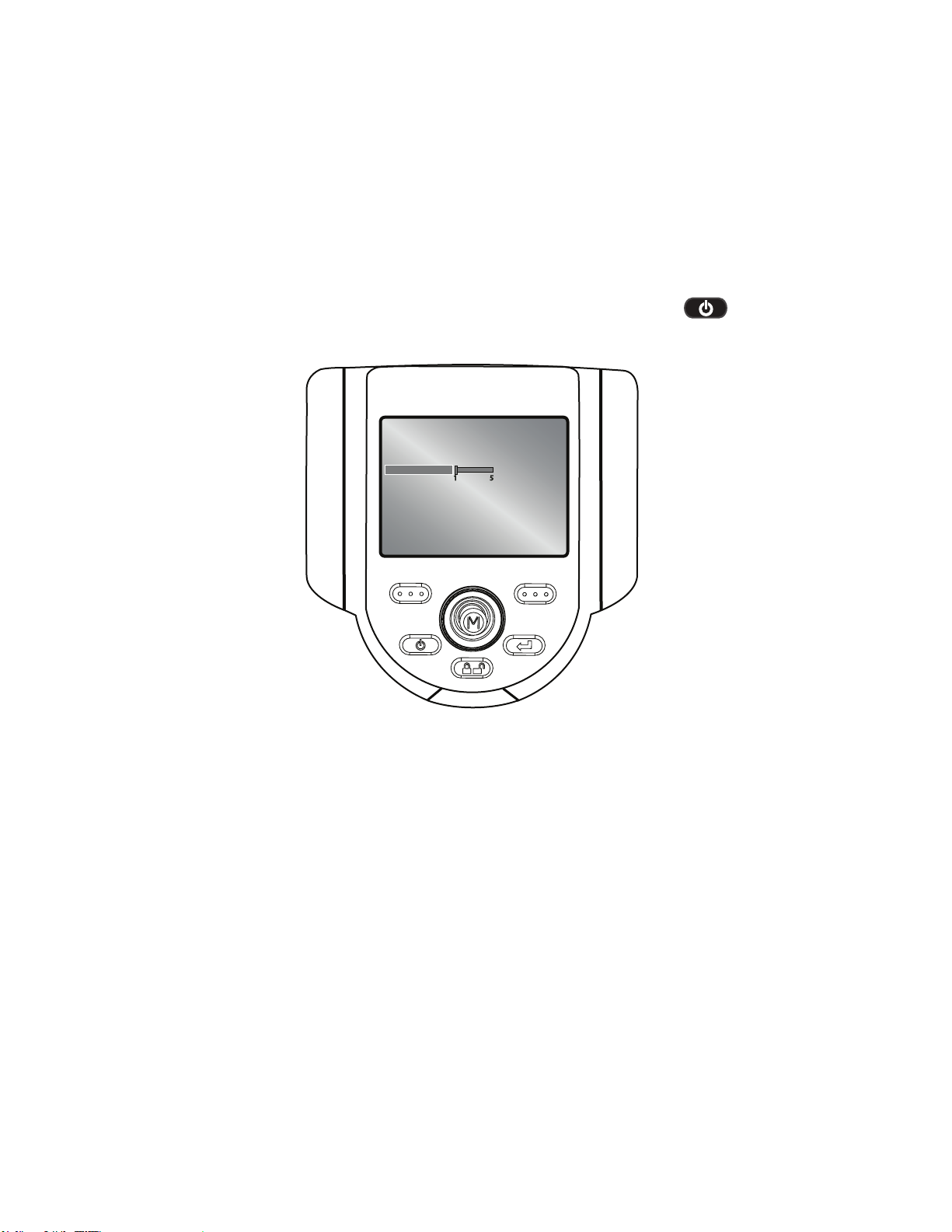
Page 74

Operation
Live Main Menu > Setup > Audio Annotation Setup >
Playback Volume
To set the playback volume, select PLAYBACK VOLUME from the
AUDIO ANNOTATION SETUP menu. Use the joystick to control the
volume from 0 to 10.
XL Flex
AUDIO PLAYBACK SETUP
PLAYBACK VOLUME
BACK SELECT
010
Note: XL Flex+ does not have a built in speaker, you must attach an
external headset in order to playback audio annotation.
74 XL Flex+™ VideoProbe
®
Page 75

Operation
Live Main Menu > Setup > Steering Setup > Steering
To manage probe articulation, select the steering increment. Options are
COARSE or FINE.
XL Flex
STEERING SETUP
STEERING
TIP MAP
BACK SELECT
X COARSE
FINE
XL Flex+™ VideoProbe® 75
Page 76

Operation
Live Main Menu > Setup > Steering Setup > Tip Map
Tip Map is a grid that indicates probe-tip position. To turn Tip Map ON or
OFF, select STEERING SETUP from the SETUP menu followed by TIP
MAP.
XL Flex
STEERING SETUP
STEERING
TIP MAP
BACK SELECT
X ON
OFF
76 XL Flex+™ VideoProbe
®
Page 77

Operation
Live Main Menu > Setup > Language Setup
To load or change the system language or external keyboard, select
LANGUAGE SETUP from the SETUP menu followed by the appropriate
language.
XL Flex
SETUP
SCREEN/DISPLAY
MEASUREMENT SETUP
VIDEO RECORD SETUP
STILL IMAGE SETUP
AUDIO ANNOTATION SETUP
STEERING
LANGUAGE SETUP
SYSTEM TOOLS
BACK SELECT
The following options are available:
• LOAD
• CHANGE
• KEYBOARD SETUP
XL Flex+™ VideoProbe® 77
Page 78

Operation
Live Main Menu > Setup > System Tools
To view system information or adjust power management, select SETUP
from the LIVE MAIN MENU followed by SYSTEM TOOLS.
XL Flex
SETUP
SCREEN/DISPLAY
MEASUREMENT SETUP
VIDEO RECORD SETUP
STILL IMAGE SETUP
AUDIO ANNOTATION SETUP
STEERING
LANGUAGE SETUP
SYSTEM TOOLS
BACK SELECT
78 XL Flex+™ VideoProbe
®
Page 79

Operation
Live Main Menu > Setup > System Tools >
System Info
To view system information such as the software version or the amount
of free disk space, select SYSTEM INFORMATION from the SYSTEM
TOOLS menu.
XL Flex
SYSTEM TOOLS
SYSTEM INFO
POWER MANAGEMENT
BACK SELECT
XL Flex+™ VideoProbe® 79
Page 80

Operation
Live Main Menu > Setup > System Tools >
Power Management
Power management enables a sleep mode / auto o to save battery
power. To enable or disable power management, select POWER
MANAGEMENT from the SYSTEM TOOLS menu followed by ON or
OFF.
XL Flex
SYSTEM TOOLS
SYSTEM INFO
POWER MANAGEMENT
BACK SELECT
ON
OFF
Sleep Mode
Occurs automatically under battery power if no buttons have been
activated for 15 minutes. Sleep mode is indicated by the push button
lights ashing in a rotating circle around the joystick.
Auto O
If sleep mode is not interrupted by any button or joystick activation within
15 minutes the system will power o to conserve battery.
80 XL Flex+™ VideoProbe
®
Page 81

Operation
Live Main Menu > File Manager
To manage les and folders on the XL Flex+ VideoProbe system, select
FILE MANAGER with the joystick. For more details refer to the FILE
MANAGEMENT section in the Operation Chapter.
XL Flex
LIVE MAIN MENU
LIGHT OUTPUT
IMAGE CONTROL
ANNOTATION
EJECT HARDWARE
SETUP
FILE MANAGER
BACK SELECT
XL Flex+™ VideoProbe® 81
Page 82

Operation
Capturing Images and Video
Steering the VideoProbe
The joystick controls articulation (steering) of the probe tip. When
viewing a live video image, move the joystick towards the desired
inspection area.
Articulation Lock
To hold the bending neck in place while steering, press and release the
Steering Control key. A lock icon will appear in the corner of the
display to symbolize steer and stay is enabled. The probe will now stay in
place when the joystick is released.
To unlock steering, press and release Steering Control again. The
lock icon will disappear.
XL Flex
RECORD GOTO
Note: While articulation lock is enabled, the XL Flex+ will steer in ne
articulation mode.
82 XL Flex+™ VideoProbe
®
Page 83

Operation
Articulation Home
Press and hold to engage HOME function to straighten bending
neck. A blinking home icon will appear on LCD when enabled.
HOME icon will disappear when system is nished.
XL Flex
RECORD GOTO
Note: It is recommended that a home operation is performed before
withdrawing the camera from the asset being inspected, to avoid getting
the camera stuck in the asset or damaging the XL Flex+.
XL Flex+™ VideoProbe® 83
Page 84

Operation
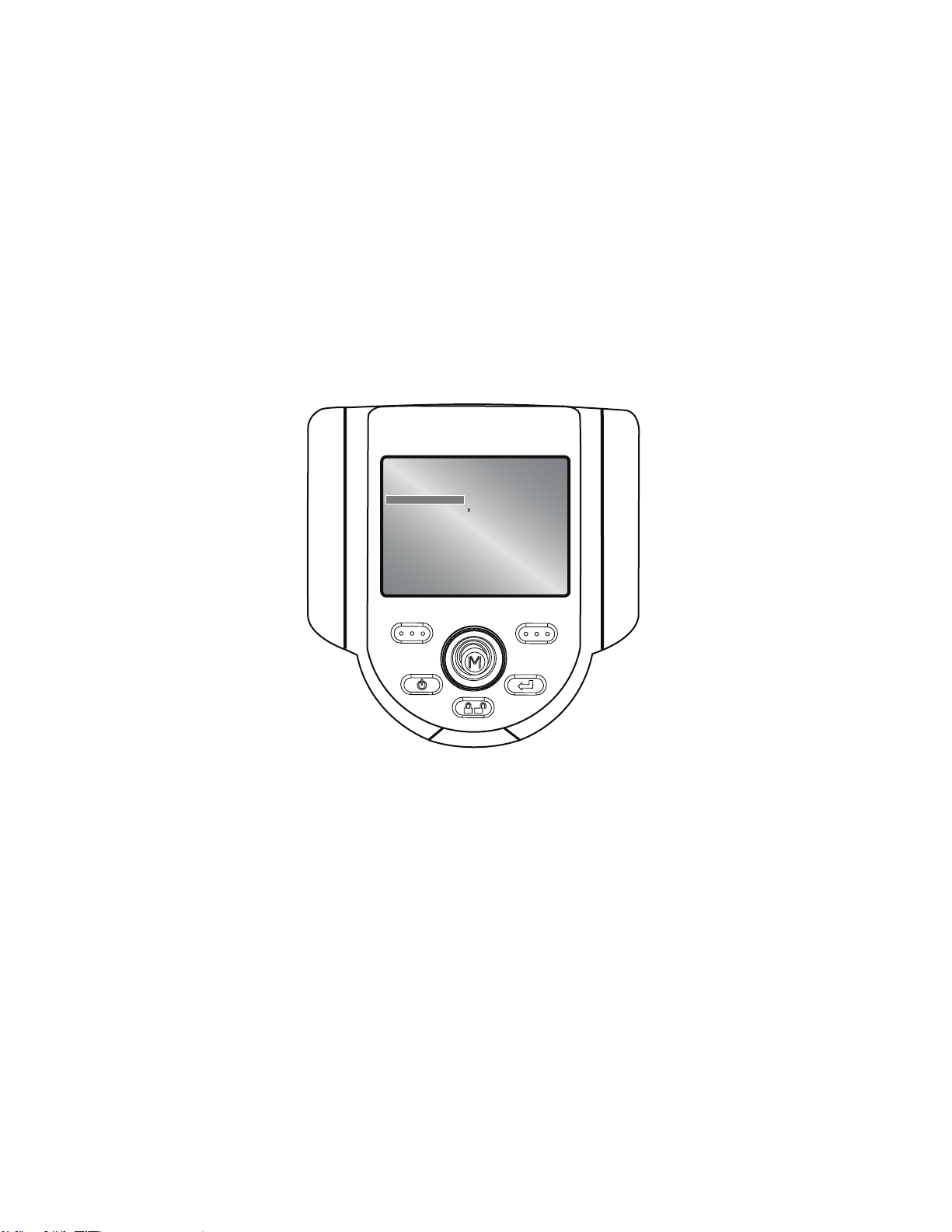
Freeze Frame
Once the inspection area is in view, the image must be frozen before it
can be measured or saved. To freeze an image, press Freeze/
Enter. An “FF” will appear in the upper right corner of the display to
symbolize that the image is frozen.
To disable Freeze Frame, press Freeze/Enter again. The “FF” will
disappear.
XL Flex
FF
MEASURE SAVE
84 XL Flex+™ VideoProbe
®
Page 85

Operation
Freeze Frame Menu
Once Freeze Frame is enabled, press the joystick to enter the FREEZE
FRAME MENU.
XL Flex
FREEZE FRAME MENU
SAVE AS
ANNOTATION
MEASURE
SPLIT SCREEN
BACK SELECT
The following options are available:
• SAVE AS
• ANNOTATION
• MEASUREMENT
• SPLIT SCREEN
XL Flex+™ VideoProbe® 85
Page 86

Operation
Freeze Frame Menu > Annotation
To add, edit or delete an annotation, or to play, stop or pause an audio
annotation, select ANNOTATION from the FREEZE FRAME MENU.
XL Flex
FREEZE FRAME MENU
SAVE AS
ANNOTATION
MEASURE
SPLIT SCREEN
BACK SELECT
The following options are available:
• TEXT
• ARROW
• PRESET
• HIDE ANNOTATION
• AUDIO
86 XL Flex+™ VideoProbe
®
Page 87

Operation
Still Image Capture and Playback
To save/capture a still image if freeze frame is enabled, press the
right soft key with SAVE on the LCD above to save to the default
location. Alternately, press and hold Freeze/Enter to auto-save.
Note: For further information see the “Save with Measurement” section.
Video Recording and Playback
To record live video, press the left soft key labeled RECORD on
the LCD above. A record symbol will appear in the upper right hand
corner. When the video is stopped, it will automatically save to the
default location.
To view recorded videos on a PC, use either QuickTime or VLC
software. Both are included with the system, located on the
documentation CD.
Still Image Capture During Video Recording
To capture a still image during viedo recording, pause the video using
the left soft key, press the Freeze/Enter button to capture
the image, press right soft key to save the image, and press
Exit to resume video recording.
XL Flex+™ VideoProbe® 87
Page 88

Operation
File Manager
To access the FILE MANAGER, press the joystick to activate the LIVE
MAIN MENU. Navigate to FILE MANAGER and select.
Recalling a File
To recall a le, select RECALL. Move the joystick to the right to locate
the le(s) and use the right soft key to select.
XL Flex
FILE MANAGER
RECALL
COPY
DELETE
SPLIT SCREEN
CREATE FOLDER
RENAME
STILL IMAGE SETUP
VIDEO RECORD SETUP
BACK SELECT
88 XL Flex+™ VideoProbe
®
Page 89

Operation
Recalled Image Menu
After recalling an image, press the joystick to activate the RECALLED
IMAGE MENU
XL Flex
RECALLED IMAGE MENU
SAVE AS
MEASURE
SPLIT SCREEN
BACK SELECT
The following options are available:
• SAVE AS
• MEASURE
• SPLIT SCREEN
XL Flex+™ VideoProbe® 89
Page 90

Operation
CK
SELE
CTCT
C
Video Playback Menu
To navigate a recalled video, either press the joystick left (rewind) or right
(fast forward) or press the left soft key to pause the video and
then press the joystick left or right. If navigating a paused video, press
the left soft key to resume playback.
XL Flex
SEEK IN PROGRESS
BACK SELECTBA
RESUME EXIT
90 XL Flex+™ VideoProbe
®
Page 91

Operation
Copying Files/Folders
To copy a le, select COPY. Move the joystick to the right to locate the
le(s) and use the right soft key to mark/unmark. Press
Freeze/Enter to copy.
Choose the destination for the copied le. Use the joystick to navigate to
the desired folder. Press Freeze/Enter to paste the copied le.
XL Flex
FILE MANAGER
RECALL
COPY
DELETE
SPLIT SCREEN
CREATE FOLDER
RENAME
STILL IMAGE SETUP
VIDEO RECORD SETUP
BACK SELECT
XL Flex+™ VideoProbe® 91
Page 92

Operation
Deleting Files/Folders
To delete a le, select DELETE FILE. Move the joystick to the right to
locate the le(s) and select. Press Freeze/Enter to delete.
XL Flex
FILE MANAGER
RECALL
COPY
DELETE
SPLIT SCREEN
CREATE FOLDER
RENAME
STILL IMAGE SETUP
VIDEO RECORD SETUP
BACK SELECT
92 XL Flex+™ VideoProbe
®
Page 93

Operation
Creating a Folder
To create a folder, select CREATE FOLDER. Select the location of the
folder. Use the joystick to highlight and Freeze/Enter to select
each letter. When done, press the right soft key to save the folder
name.
XL Flex
FILE MANAGER
RECALL
COPY
DELETE
SPLIT SCREEN
CREATE FOLDER
RENAME
STILL IMAGE SETUP
VIDEO RECORD SETUP
BACK SELECT
XL Flex+™ VideoProbe® 93
Page 94

Operation
Renaming Files/Folder
To rename a le, select RENAME. Navigate to the desired le/folder
and use the right soft key to select. Use the joystick to highlight
and Freeze/Enter to select each letter. When nished, press the
right soft key to save the le name.
XL Flex
FILE MANAGER
RECALL
COPY
DELETE
SPLIT SCREEN
CREATE FOLDER
RENAME
STILL IMAGE SETUP
VIDEO RECORD SETUP
BACK SELECT
94 XL Flex+™ VideoProbe
®
Page 95

Measurement
About Measurement
Measurement capability is enabled once measurement tips have been
calibrated to the XL Flex+ system. Features and defects may be
measured either before or after saving an image (if the image was saved
in measurement mode). Up to ve measurements can be saved per
image.
Measurement results are valid only for measurements taken in air.
For measurements taken in liquid, contact GE Sensing and Inspection
Technologies.
A measurement accuracy verication block is supplied with the purchase
of measurement tips. Perform a measurement on this verication block
to check accuracy. See Appendix D for help with using the verication
block.
All measurement images saved using the XL Flex+ system can be remeasured on a PC using Inspection Manager or iViewPC software.
Measurement File Formats
Measurement images, such as, JPEGs or bitmaps can be saved. These
les can also be viewed including the measurement results, in most
.BMP or .JPG viewing applications, such as Windows™ Paint. To learn
how to change the le format, see STILL IMAGE SETUP > FORMAT >
JPEG QUALITY.
NOTE: The .BMP le format is recommended for measurement
image capture.
Measurement Optical Tips
StereoProbe® measurement tips are factory-calibrated for use with
specic probes. Tips are matched to systems by the serial numbers
identied on each optical tip. A label located in USB1 bay indicates which
tips are calibrated to the probe.
To ensure that no mechanical damage has degraded tip accuracy, verify
measurement tips each time they are used. See Verifying Measurement
Tips in the Appendix.
XL Flex+™ VideoProbe® 95
Page 96

Measurement
See the Optical Tip Table in Appendix for a complete list of optical tips.
Measurement Procedure
Attach a measurement optical tip, position the probe for maximum
accuracy and freeze the image. Using the left soft key,
select Measurement. Choose the measurement tip and the type of
measurement. Position the cursor and press Freeze/Enter to save
the cursor placement. Repeat with remaining cursor(s).
Capturing Measurement Images for Re-Measurement
Stereo measurement images can be saved allowing the user to perform
the actual measurements at a later time on the XL Flex+, Rhythm Review
station, or on a PC using the Inspection Manager software
Measurement Procedure
Attach a measurement optical tip, position the probe for maximum
accuracy and freeze the image to be saved for re-measurement. Press
the joystick’s Main Menu button. Select ‘Save As” and press select
‘Measurement’ and press . Complete other optional elds and
press . When complete, use the soft key, select DONE.
Accuracy Index
The accuracy index is a number that indicates the amount of
magnication during stereo measurements. The higher the accuracy
index, the greater the magnication. The greater the magnication, the
more accurately you can place the measurement cursors allowing for
more accurate results.
96 XL Flex+™ VideoProbe
®
Page 97

Measurement
StereoProbe Measurement
Stereo measurements may be taken with the probe perpendicular or not
perpendicular to the target.
Types of StereoProbe Measurement
• Length
• Point to Line
• Depth
• Area
• Multi-Segment Line
XL Flex+™ VideoProbe® 97
Page 98

Measurement
Comparison Measurement
Comparison measurements are to be taken when an item in the image
has a known dimension and that item’s dimension is used as a reference
to measure other items.
Measurement
Type
Stereo Over comparison
Comparison • Use standard optical
Advantages Disadvantages
measurements:
• More accurate
• No known reference
is needed
• Measure depth
• Surface does
not need to be
perpendicular to the
prove view.
• The surface does
not need to be
perpendicular to the
probe view.
tip
• Measure with tip
further away
• Measure large objects
• Check the
approximate size of
many items quickly
The system may be
unable to position
matching cursors
accurately with any of
these conditions in the
measurement area:
• Insucient detail
• Repeating patterns
• Glare
• Smooth, straight lines
to measure along
In some cases, the
problem can be eliminated
by repositioning the probe
tip and adjusting the
brightness.
• Less accurate than
stereo measurement
• Known references
may not be present
and may be dicult
to deliver to the
measurement site
• Measurement surface
must be nearly
perpendicular to
the probe view for
accurate results
98 XL Flex+™ VideoProbe
®
Page 99

Measurement
StereoProbe Measurement
Stereo measurements require the use of StereoProbe measurement
tips, which capture stereoscopic images of a target — two pictures of
the same target from two dierent angles. To measure the target, the
XL Flex+ processor uses triangulation based on these two side-by-side
images. Stereo measurements can be taken on a frozen image or on a
recalled image that was saved in measurement mode.
Positioning the Probe Tip for Maximum Accuracy
Before freezing a stereo measurement image, position the probe tip to
meet these criteria:
Visibility: The item to be measured is fully visible in the left and right
images.
Tip-to-target proximity: The probe is positioned as close to the target as
possible while keeping it in focus.
Vertical orientation: If measuring distance between lines or across a
circle, the image is oriented so that cursors can be placed at the left and
right edges of the item to be measured — not at top, bottom, or diagonal
points. The system needs dierentiated details to the left and right of
each cursor to accurately place the matching cursors on the right image.
Minimal glare: Glare is minimized by adjusting the viewing angle and the
image brightness in the areas where cursors will be placed. Small glare
speckles do not present a problem, but larger glare areas may appear in
dierent positions on the two sides causing false matches.
XL Flex+ ™ VideoProbe® 99
Page 100

Measurement
Bad Example
• Object is not fully visible on
right side.
• Object is not well lit.
• Object is not oriented
to allow proper cursor
placement.
Good Example
• Object is fully visible on both
sides.
• Object is well lit.
• Object is oriented to allow
proper cursor placement.
Accuracy Index
The accuracy index is a number that indicates the amount of
magnication during stereo measurements. The higher the accuracy
index, the greater the magnication. The greater the magnication, the
more accurately you can place the measurement cursors allowing for
more accurate results.
When taking stereo measurements, you magnify the image, not by
zooming but by moving the optical tip as close as you can to the target.
100 XL Flex+™ VideoProbe
®
 Loading...