

Page 1
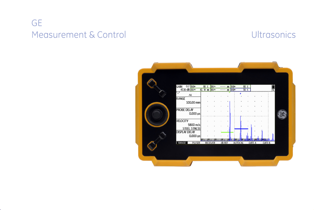
USM Go
USM Go+
Technical Reference and Operating Manual Id. No. 49 155
Page 2

This issue 6 (02/2013) applies to the following software versions:
USM Go: 2.08 (March 6, 2013)
USM Go+: 2.08 (May 28, 2013)
You will find the software version and the serial number of your instrument on the second operating level
(CONFIG2 - ABOUT)
© GE Sensing & Inspection Technologies GmbH | Technical content subject to change without notice.
Page 3
First operating level (Base)
To change between the first and the second operating level:
USM Go: Press the joystick for 2 seconds.
USM Go+: Press the center key of the keypad for 2 seconds.
USM Go Issue 6 (02/2013) 0-3
Page 4
First operating level (Options)
To change between the first and the second operating level:
USM Go: Press the joystick for 2 seconds.
USM Go+: Press the center key of the keypad for 2 seconds.
0-4 Issue 6 (02/2013) USM Go
Page 5
Second operating level
USM Go Issue 6 (02/2013) 0-5
Page 6
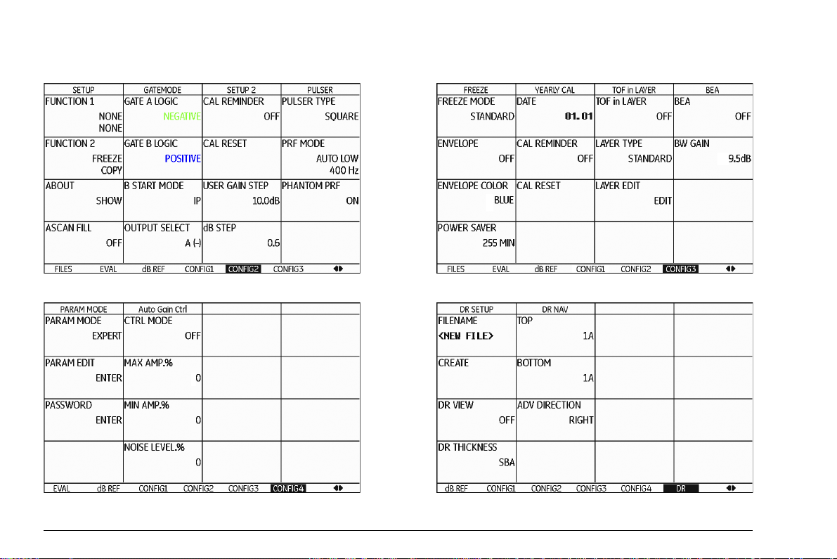
Second operating level (continued)
0-6 Issue 6 (02/2013) USM Go
Page 7
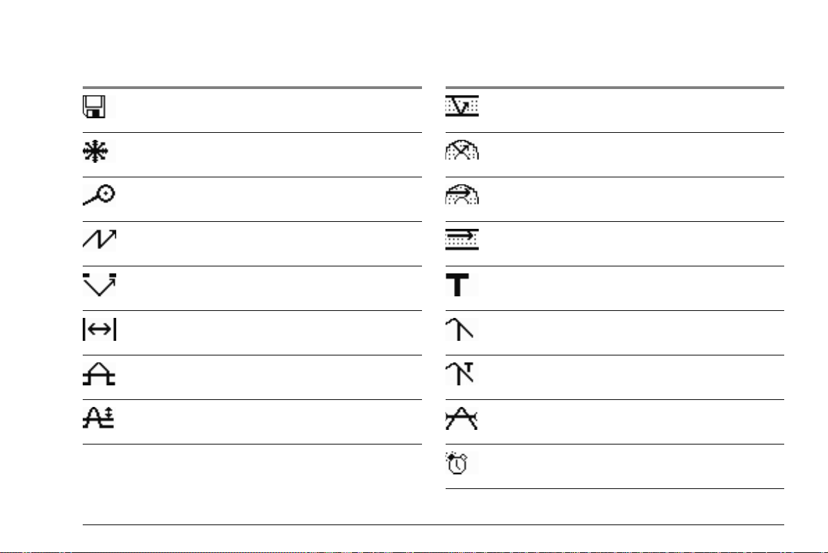
Status display icons
Icon Meaning Icon Meaning
SD memory card is inserted,
flashes when the SD card is accessed
Angle-beam probe 30° … 90°, flat surface,
Reflection from the backwall
Freeze active (Freeze),
Display is „frozen“.
Angle-beam probe 30°, curved surface,
Reflection from the inner surface of tube
Magnify gate is active Angle-beam probe 80°, curved surface,
Reflection from the outer surface of tube
Pulser-receiver separation is turned off Angle-beam probe 90°, surface wave
Pulser-receiver separation is turned on DAC mode = TCG is active
Pulser-receiver separation is turned on and set
DGS reference echo has been recorded
to through-transmission mode
Reject function is active DGS reference echo has been recorded,
transfer loss > 0
AGT is active dB REF is active
Calibration reminder
USM Go Issue 6 (02/2013) 0-7
Page 8
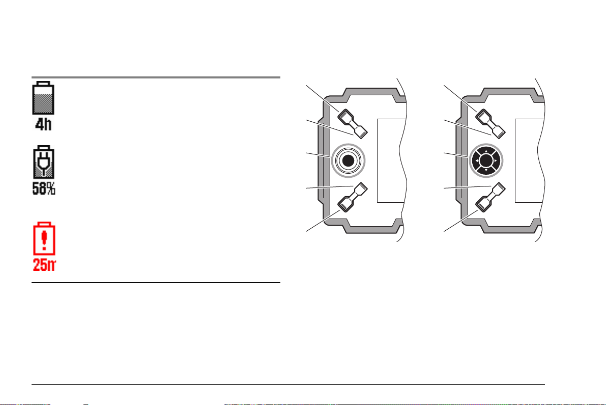
Power level indicators Keypad functions
3
4
2
2
3
4
5
5
USM Go USM Go+
Icon Meaning
Battery charge level,
remaining operating time
in hours (approximate value)
Charger/power adapter is connected,
percentage of battery charge level
(approximate value)
Warning: Low battery charge level,
remaining operating time
in minutes (approximate value)
1
1
1 Increasing the gain level in increments
2 Decreasing the gain level in increments
3 Navigation operating levels and function groups
4 Function key 1, individually assignable
5 Function key 2, individually assignable
0-8 Issue 6 (02/2013) USM Go
Page 9
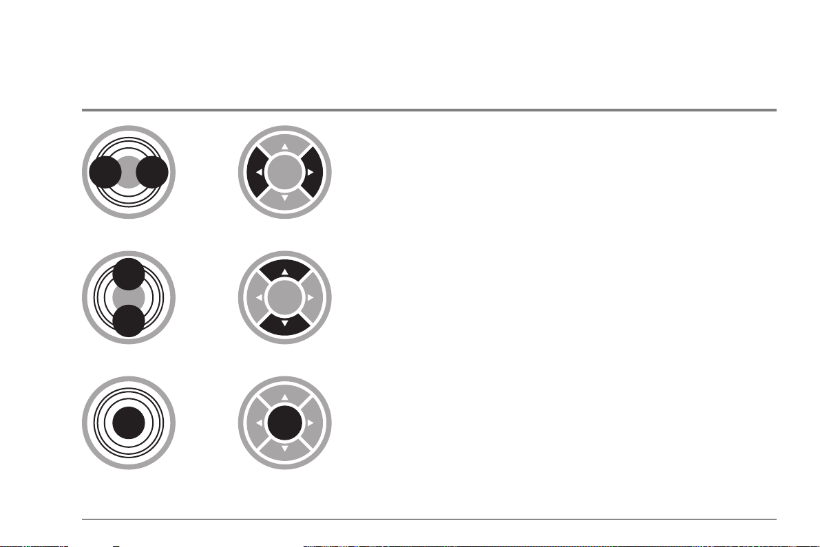
Navigation using joystick (USM Go) or keypad (USM Go+)
USM Go USM Go+ Function
Navigation between function groups,
adjusting values
Navigation within a function group,
adjusting values
Changing between operating levels (press for 2 seconds)
USM Go Issue 6 (02/2013) 0-9
Page 10

0-10 Issue 6 (02/2013) USM Go
Page 11

Contents
0 Übersichten
First operating level (Base). . . . . . . . . . . . 0-3
First operating level (Options). . . . . . . . . . 0-4
Second operating level . . . . . . . . . . . . . . . 0-5
Second operating level (continued) . . . . . 0-6
Status display icons . . . . . . . . . . . . . . . . . 0-7
Power level indicators. . . . . . . . . . . . . . . . 0-8
Keypad functions . . . . . . . . . . . . . . . . . . . 0-8
Navigation using joystick (USM Go)
or keypad (USM Go+). . . . . . . . . . . . . . . . 0-9
1 Introduction
1.1 Safety information . . . . . . . . . . . . . . . . . 1-2
Battery operation . . . . . . . . . . . . . . . . . . . 1-2
Software . . . . . . . . . . . . . . . . . . . . . . . . . . 1-2
Defects/errors and exceptional stresses. . 1-3
1.2 Important information on
ultrasonic testing . . . . . . . . . . . . . . . . . . 1-3
Prerequisites for testing with
ultrasonic test equipment . . . . . . . . . . . . . 1-3
Operator training . . . . . . . . . . . . . . . . . . . . 1-4
Technical test requirements . . . . . . . . . . . 1-4
Limits of testing . . . . . . . . . . . . . . . . . . . . . 1-5
Ultrasonic wall thickness measurement . . 1-5
Effect of the test object material . . . . . . . . 1-5
Effect of temperature variations . . . . . . . . 1-6
Measurement of remaining wall thickness 1-6
Ultrasonic evaluation of flaws . . . . . . . . . . 1-6
Flaw boundary method . . . . . . . . . . . . . . . 1-6
Echo display comparison method . . . . . . . 1-7
1.3 The USM Go. . . . . . . . . . . . . . . . . . . . . . . 1-8
Instrument versions USM Go and USM Go+1-9
Options . . . . . . . . . . . . . . . . . . . . . . . . . . 1-10
Special features of the USM Go . . . . . . . 1-11
1.4 The DMS Go. . . . . . . . . . . . . . . . . . . . . . 1-12
1.5 How to use this manual . . . . . . . . . . . . 1-12
USM Go Issue 6 (02/2013) 0-1
Page 12

Contents
1.6 Layout and presentation in
this manual . . . . . . . . . . . . . . . . . . . . . . 1-13
Attention and note symbols. . . . . . . . . . . 1-13
Listings . . . . . . . . . . . . . . . . . . . . . . . . . . 1-13
Operating steps. . . . . . . . . . . . . . . . . . . . 1-13
2 Standard package and accessories
2.1 Standard package . . . . . . . . . . . . . . . . . . 2-2
2.2 Add-on functions . . . . . . . . . . . . . . . . . . 2-3
2.3 Preconfigured function packages. . . . . 2-4
2.4 Recommended accessories. . . . . . . . . . 2-5
3 Initial start-up
3.1 Instrument positioning . . . . . . . . . . . . . . 3-2
3.2 Power supply. . . . . . . . . . . . . . . . . . . . . . 3-2
Operation with charger/power adapter . . . 3-2
Operation using batteries . . . . . . . . . . . . . 3-4
Charging the batteries. . . . . . . . . . . . . . . . 3-8
3.3 Connecting a probe . . . . . . . . . . . . . . . . 3-9
3.4 Inserting the SD memory card. . . . . . . 3-10
3.5 Starting the USM Go . . . . . . . . . . . . . . . 3-11
Powering On . . . . . . . . . . . . . . . . . . . . . . 3-11
Powering Off . . . . . . . . . . . . . . . . . . . . . . 3-12
Factory default setting (Reset) . . . . . . . . 3-12
4 Principles of operation
4.1 Overview of operator's controls . . . . . . 4-2
4.2 Display screen. . . . . . . . . . . . . . . . . . . . . 4-3
A-scan representation . . . . . . . . . . . . . . . . 4-3
Functions on the display screen . . . . . . . . 4-4
Gain. . . . . . . . . . . . . . . . . . . . . . . . . . . . . . 4-5
Measurement line . . . . . . . . . . . . . . . . . . . 4-5
Status display icons . . . . . . . . . . . . . . . . . 4-6
Alarms . . . . . . . . . . . . . . . . . . . . . . . . . . . . 4-6
0-2 Issue 6 (02/2013) USM Go
Page 13

Contents
4.3 Navigation and function keys . . . . . . . . 4-7
Navigation. . . . . . . . . . . . . . . . . . . . . . . . . 4-7
Function keys . . . . . . . . . . . . . . . . . . . . . . 4-7
Key combinations . . . . . . . . . . . . . . . . . . . 4-8
Power key . . . . . . . . . . . . . . . . . . . . . . . . . 4-8
4.4 Operational concept . . . . . . . . . . . . . . . . 4-9
Operating levels . . . . . . . . . . . . . . . . . . . . 4-9
Selecting and setting functions . . . . . . . . . 4-9
Function HOME . . . . . . . . . . . . . . . . . . . 4-11
Activating functions. . . . . . . . . . . . . . . . . 4-12
4.5 Important default settings . . . . . . . . . . 4-13
Language setting . . . . . . . . . . . . . . . . . . 4-13
Units setting . . . . . . . . . . . . . . . . . . . . . . 4-14
Decimal separator. . . . . . . . . . . . . . . . . . 4-14
Date format, Date, and Time . . . . . . . . . 4-15
Selecting the instrument orientation . . . . 4-16
4.6 Default settings of the display. . . . . . . 4-16
Selecting the color scheme. . . . . . . . . . . 4-16
Selecting the A-scan color . . . . . . . . . . . 4-17
Selecting the grid . . . . . . . . . . . . . . . . . . 4-18
Setting the brightness . . . . . . . . . . . . . . . 4-18
4.7 Saving the settings. . . . . . . . . . . . . . . . 4-19
Recalling settings . . . . . . . . . . . . . . . . . . 4-21
Displaying dataset name. . . . . . . . . . . . . 4-22
5 Operation
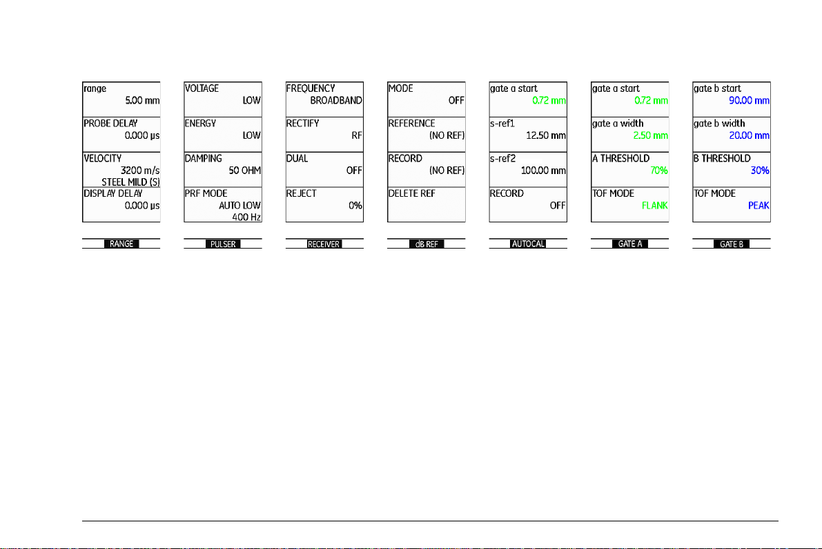
5.1 Overview of the functions . . . . . . . . . . . 5-2
Function groups first operating level . . . . . 5-3
Function groups second operating level . . 5-4
5.2 Setting the gain. . . . . . . . . . . . . . . . . . . . 5-6
Setting the dB increment of gain. . . . . . . . 5-6
5.3 Assignment of function keys. . . . . . . . . 5-8
5.4 Setting the display range
(function group RANGE) . . . . . . . . . . . 5-10
RANGE . . . . . . . . . . . . . . . . . . . . . . . . . . 5-11
PROBE DELAY. . . . . . . . . . . . . . . . . . . . 5-11
VELOCITY . . . . . . . . . . . . . . . . . . . . . . . 5-12
DISPLAY DELAY . . . . . . . . . . . . . . . . . . 5-13
USM Go Issue 6 (02/2013) 0-3
Page 14

Contents
5.5 Setting the pulser
(function group PULSER). . . . . . . . . . . 5-14
VOLTAGE (pulser voltage) . . . . . . . . . . . 5-14
ENERGY. . . . . . . . . . . . . . . . . . . . . . . . . 5-15
WIDTH . . . . . . . . . . . . . . . . . . . . . . . . . . 5-16
DAMPING . . . . . . . . . . . . . . . . . . . . . . . . 5-17
PRF MODE (pulse repetition frequency) . .5-17
5.6 Setting the receiver
(function group RECEIVER). . . . . . . . . 5-19
FREQUENCY . . . . . . . . . . . . . . . . . . . . . 5-19
RECTIFY. . . . . . . . . . . . . . . . . . . . . . . . . 5-20
DUAL (pulser-receiver separation) . . . . . 5-20
REJECT . . . . . . . . . . . . . . . . . . . . . . . . . 5-21
5.7 Setting the gates
(function groups
GATE A and GATE B) . . . . . . . . . . . . . . 5-22
Tasks of the gates. . . . . . . . . . . . . . . . . . 5-22
A-START/B-START
(starting point of the gate) . . . . . . . . . . . . 5-23
A-WIDTH/B-WIDTH
(width of the gates) . . . . . . . . . . . . . . . . . 5-23
A-THRESHOLD/B-THRESHOLD
(response and measurement
threshold of the gate) . . . . . . . . . . . . . . . 5-24
TOF MODE . . . . . . . . . . . . . . . . . . . . . . . 5-25
Starting point of gate B . . . . . . . . . . . . . . 5-27
Automatic gate height . . . . . . . . . . . . . . . 5-28
5.8 Calibrating the USM Go . . . . . . . . . . . . 5-29
Calibrating the display range. . . . . . . . . . 5-29
Choice of the measuring point . . . . . . . . 5-29
Calibration with straight-beam and
angle-beam probes . . . . . . . . . . . . . . . . . 5-30
Calibration using dual-element probes . . 5-34
5.9 Making measurements . . . . . . . . . . . . . 5-37
General notes . . . . . . . . . . . . . . . . . . . . . 5-37
5.10 dB-difference measurement
(function group dB REF) . . . . . . . . . . . 5-38
Recording a reference echo . . . . . . . . . . 5-39
Deleting a reference echo . . . . . . . . . . . . 5-39
Echo height comparison . . . . . . . . . . . . . 5-40
0-4 Issue 6 (02/2013) USM Go
Page 15

Contents
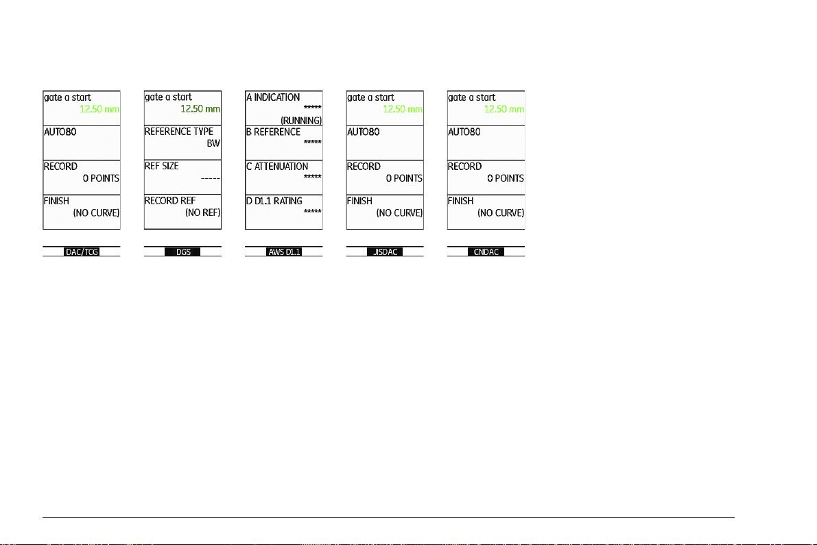
5.11 Rating of welds
(function group AWS D1.1) . . . . . . . . . 5-41
Rating of welds according to AWS D1.1. 5-42
5.12 Flaw position calculation with
angle-beam probes. . . . . . . . . . . . . . . . 5-45
PROBE ANGLE . . . . . . . . . . . . . . . . . . . 5-46
THICKNESS . . . . . . . . . . . . . . . . . . . . . . 5-47
X VALUE. . . . . . . . . . . . . . . . . . . . . . . . . 5-48
O-DIAMETER . . . . . . . . . . . . . . . . . . . . . 5-48
COLOR LEG. . . . . . . . . . . . . . . . . . . . . . 5-49
5.13 Defining the probe angle . . . . . . . . . . . 5-50
BLOCK . . . . . . . . . . . . . . . . . . . . . . . . . . 5-51
5.14 Enabling options (Upgrade). . . . . . . . . 5-52
5.15 Configuring the USM Go for
test tasks . . . . . . . . . . . . . . . . . . . . . . . . 5-53
TOF MODE. . . . . . . . . . . . . . . . . . . . . . . 5-53
Phantom echo detector. . . . . . . . . . . . . . 5-58
Configuring the measurement line . . . . . 5-59
Enlarged display of reading . . . . . . . . . . 5-62
LARGE (alarm signal). . . . . . . . . . . . . . . 5-64
MAGNIFY GATE (spanning the gate). . . 5-65
Activating the magnify gate function . . . . 5-66
Automatic A-scan freeze (Freeze) . . . . . 5-68
5.16 Setting the display . . . . . . . . . . . . . . . . 5-70
ASCAN FILL . . . . . . . . . . . . . . . . . . . . . . 5-71
Working with Echo Max . . . . . . . . . . . . . 5-72
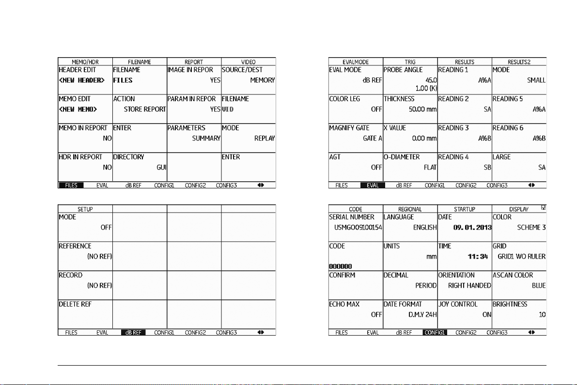
5.17 General setup . . . . . . . . . . . . . . . . . . . . 5-73
EVAL MODE . . . . . . . . . . . . . . . . . . . . . . 5-73
Gate logic . . . . . . . . . . . . . . . . . . . . . . . . 5-74
Selecting the pulser type. . . . . . . . . . . . . 5-75
Locking the joystick. . . . . . . . . . . . . . . . . 5-76
Configuring the alarm output. . . . . . . . . . 5-77
Power saving mode . . . . . . . . . . . . . . . . 5-79
TOF in LAYER . . . . . . . . . . . . . . . . . . . . 5-80
Backwall echo attenuation (BEA) . . . . . . 5-82
Displaying the envelope curve
(ENVELOPE) . . . . . . . . . . . . . . . . . . . . . 5-83
Automatic gain control
(Auto Gain Control) . . . . . . . . . . . . . . . . . 5-84
USM Go Issue 6 (02/2013) 0-5
Page 16

Contents
Calibration reminder . . . . . . . . . . . . . . . . 5-86
Password protection . . . . . . . . . . . . . . . . 5-87
5.18 Distance-amplitude correction (DAC) . 5-91
Recording a DAC curve . . . . . . . . . . . . . 5-92
Setting up the DAC . . . . . . . . . . . . . . . . . 5-94
Turning the DAC evaluation off. . . . . . . . 5-95
Deleting the DAC curve . . . . . . . . . . . . . 5-96
Editing DAC points . . . . . . . . . . . . . . . . . 5-96
Adding DAC points . . . . . . . . . . . . . . . . . 5-97
Multiple DAC curves . . . . . . . . . . . . . . . . 5-97
AWS D1.1 in DAC/TCG . . . . . . . . . . . . . 5-99
Sensitivity correction . . . . . . . . . . . . . . . . 5-99
Echo evaluation using DAC/TCG . . . . . 5-100
5.19 Distance-amplitude curve according to
JIS Z3060-2002 (JISDAC) . . . . . . . . . . 5-102
Activating JISDAC
(DAC according to JIS) . . . . . . . . . . . . 5-102
Recording a DAC curve . . . . . . . . . . . . 5-102
Setting up JISDAC . . . . . . . . . . . . . . . . 5-105
Sensitivity correction . . . . . . . . . . . . . . . 5-106
Turning the JISDAC evaluation off . . . . 5-106
Deleting the DAC curve. . . . . . . . . . . . . 5-107
Echo evaluation using DAC . . . . . . . . . 5-107
5.20 Distance-amplitude curve
according to JB/T4730 and
GB 11345 (CNDAC) . . . . . . . . . . . . . . . 5-109
Evaluations according to CNDAC . . . . . 5-109
Standards and reference blocks . . . . . . 5-110
Activating the CNDAC. . . . . . . . . . . . . . 5-111
Recording a DAC curve . . . . . . . . . . . . 5-111
Setting up CNDAC . . . . . . . . . . . . . . . . 5-114
Sensitivity correction . . . . . . . . . . . . . . . 5-115
Adjusting reference lines. . . . . . . . . . . . 5-116
Turning the CNDAC evaluation off . . . . 5-116
Deleting the DAC curve. . . . . . . . . . . . . 5-117
Echo evaluation using DAC . . . . . . . . . 5-117
5.21 Evaluation according to the
DGS method . . . . . . . . . . . . . . . . . . . . 5-119
Using the DGS for measurements . . . . 5-119
Validity of the DGS method. . . . . . . . . . 5-121
0-6 Issue 6 (02/2013) USM Go
Page 17

Contents
Starting the echo height evaluation
according to DGS . . . . . . . . . . . . . . . . . 5-123
Basic settings for the
DGS measurement . . . . . . . . . . . . . . . . 5-123
Recording a reference echo and
turning the DGS curve on . . . . . . . . . . . 5-125
Locks, error messages . . . . . . . . . . . . . 5-127
Sound attenuation and
transfer correction. . . . . . . . . . . . . . . . . 5-128
Using multiple DGS curves. . . . . . . . . . 5-128
Turning the DGS evaluation off . . . . . . 5-129
Deleting a DGS reference echo . . . . . . 5-129
Probe data . . . . . . . . . . . . . . . . . . . . . . 5-130
trueDGS angle-beam probes . . . . . . . . 5-133
6 Documentation
6.1 Test reports. . . . . . . . . . . . . . . . . . . . . . . 6-2
Storing test reports . . . . . . . . . . . . . . . . . . 6-2
Displaying test reports . . . . . . . . . . . . . . . 6-4
Printing test reports. . . . . . . . . . . . . . . . . . 6-6
Deleting test reports . . . . . . . . . . . . . . . . . 6-7
Storing the A-scan and parameters
in the test report . . . . . . . . . . . . . . . . . . . . 6-9
6.2 Storing memos . . . . . . . . . . . . . . . . . . . 6-10
Creating a new memo file . . . . . . . . . . . . 6-10
Editing a memo file . . . . . . . . . . . . . . . . . 6-11
Attaching a memo file to test report . . . . 6-12
6.3 Storing a report header . . . . . . . . . . . . 6-13
Creating a new header file . . . . . . . . . . . 6-13
Editing a header file . . . . . . . . . . . . . . . . 6-14
Including a header file in the test report . 6-15
6.4 Viewing and storing parameters . . . . . 6-16
6.5 Videos . . . . . . . . . . . . . . . . . . . . . . . . . . 6-17
Recording a video . . . . . . . . . . . . . . . . . . 6-17
Viewing a video. . . . . . . . . . . . . . . . . . . . 6-19
6.6 Documentation using UltraMATE . . . . 6-21
6.7 Data Recorder (option). . . . . . . . . . . . . 6-22
Creating a Data Recorder file . . . . . . . . . 6-23
Activating a Data Recorder file . . . . . . . . 6-25
Storing readings in the grid matrix . . . . . 6-26
USM Go Issue 6 (02/2013) 0-7
Page 18

Deleting readings . . . . . . . . . . . . . . . . . . 6-27
A-scan preview . . . . . . . . . . . . . . . . . . . . 6-28
Viewing Data Recorder files . . . . . . . . . . 6-28
Turning the grid matrix on/off . . . . . . . . . 6-29
Service interface (Mini RS232-C) . . . . . . . 8-3
8.2 Peripherals. . . . . . . . . . . . . . . . . . . . . . . . 8-4
9 Appendix
7 Maintenance and care
7.1 Instrument care. . . . . . . . . . . . . . . . . . . . 7-2
7.2 Battery care . . . . . . . . . . . . . . . . . . . . . . . 7-2
Battery care. . . . . . . . . . . . . . . . . . . . . . . . 7-2
Charging the batteries. . . . . . . . . . . . . . . . 7-3
7.3 Maintenance . . . . . . . . . . . . . . . . . . . . . . 7-3
7.4 Software updates . . . . . . . . . . . . . . . . . . 7-4
Download of update files. . . . . . . . . . . . . . 7-4
Installing an update. . . . . . . . . . . . . . . . . . 7-5
8 Interfaces and Peripherals
8.1 Interfaces. . . . . . . . . . . . . . . . . . . . . . . . . 8-2
Overview . . . . . . . . . . . . . . . . . . . . . . . . . . 8-2
USB interface . . . . . . . . . . . . . . . . . . . . . . 8-3
0-8 Issue 6 (02/2013) USM Go
9.1 Function directory. . . . . . . . . . . . . . . . . . 9-2
9.2 EU Declaration of Conformity . . . . . . . 9-11
9.3 Manufacturer/Service addresses. . . . . 9-11
9.4 Environmental protection regulations 9-13
WEEE directive (Waste Electrical and
Electronic Equipment) . . . . . . . . . . . . . . . 9-13
Disposal of batteries . . . . . . . . . . . . . . . . 9-14
9.5 Recycling directives . . . . . . . . . . . . . . . 9-16
Overview . . . . . . . . . . . . . . . . . . . . . . . . . 9-16
Materials to be disposed of separately . . 9-19
Other materials and components . . . . . . 9-22
Recycling data of the USM Go . . . . . . . . 9-29
Page 19

10 Specifications
10.1 Specifications of
USM Go and USM Go+ . . . . . . . . . . . . . 10-2
Display screen . . . . . . . . . . . . . . . . . . . . 10-2
Display . . . . . . . . . . . . . . . . . . . . . . . . . . 10-3
Connectors . . . . . . . . . . . . . . . . . . . . . . . 10-3
Memory. . . . . . . . . . . . . . . . . . . . . . . . . . 10-4
Pulser . . . . . . . . . . . . . . . . . . . . . . . . . . . 10-4
Receiver . . . . . . . . . . . . . . . . . . . . . . . . . 10-5
Gates . . . . . . . . . . . . . . . . . . . . . . . . . . . 10-6
Memory. . . . . . . . . . . . . . . . . . . . . . . . . . 10-6
Environment . . . . . . . . . . . . . . . . . . . . . . 10-7
Protection . . . . . . . . . . . . . . . . . . . . . . . . 10-8
Options . . . . . . . . . . . . . . . . . . . . . . . . . . 10-9
10.2 Specifications according to
EN 12668 . . . . . . . . . . . . . . . . . . . . . . . 10-11
Contents
11 Index
USM Go Issue 6 (02/2013) 0-9
Page 20

0-10 Issue 6 (02/2013) USM Go
Page 21

Introduction 1
USM Go Issue 6 (02/2013) 1-1
Page 22

1 Introduction Safety information
ATTENTION
1.1 Safety information
The USM Go has been designed and tested according
to DIN
EN 61010-1: 2011-07, Safety requirements for
electrical equipment for measurement, control and lab
oratory use, and was technically in perfectly safe and
faultless condition when leaving the manufacturing
works.
In order to maintain this condition and to ensure a safe
operation, you should always read the following safety
information carefully before putting the instrument into
operation.
The USM Go is an instrument for materials testing. Any use for medical or any
other applications is not permitted!
The instrument may only be used in industrial environments.
The USM Go is waterproof according to IP67. It can be
operated either with the corresponding lithium-ion bat
teries or with the charger/power adapter. The charger/
power adapter meets the requirements of electrical
safety class II.
-
Battery operation
For the battery operation of the USM Go, we recommend the corresponding lithium-ion battery. You should
only use this battery for the battery operation.
You can charge the lithium-ion battery either within the
instrument itself or in an external charger. If a lithium-ion
battery is inserted, charging starts automatically as
soon as you connect the charger/power adapter to the
USM Go and to the mains power supply.
For power supply, please also see Chapter 3.2 Power
supply, page 3-2. For the use of batteries, please also
see Chapter 7.2 Battery care, page 7-2.
Software
According to the current state of the art, software is never completely free from errors. Before using any software-controlled test equipment, it is therefore necessary to make sure that the required functions operate
perfectly in the intended combination.
If you have any questions about the use of your test
equipment, please contact your nearest representative
of GE Sensing & Inspection Technologies.
1-2 Issue 6 (02/2013) USM Go
Page 23

Important information on ultrasonic testing 1 Introduction
Defects/errors and exceptional stresses
If you have reason to believe that a safe operation of
your USM Go is no longer possible, you have to discon
nect the instrument and secure it against unintentional
re-connection. Remove the lithium-ion battery.
A safe operation is no longer possible for example
● if the instrument shows visible damages,
● if the instrument no longer operates perfectly,
● after prolonged storage under adverse conditions
(e.g. exceptional temperatures or especially high air
humidity, or corrosive environmental conditions),
● after being subjected to heavy stresses during transportation.
1.2 Important information on ultrasonic testing
Please read the following information before using your
USM Go. It is important that you understand and ob
serve this information to avoid any operator errors that
might lead to false test results. Such false test results
could result in personal injuries or property damages.
Prerequisites for testing with ultrasonic test equipment
This operating manual contains essential information on
how to operate your test equipment. In addition, there
are a number of factors that affect the test results, but a
description of all these factors goes beyond the scope
of this operating manual. The three most important pre
requisites for a safe and reliable ultrasonic inspection
are:
● Operator training
● Knowledge of special technical test requirements and
limits
-
-
● Choice of appropriate test equipment
USM Go Issue 6 (02/2013) 1-3
Page 24

1 Introduction Important information on ultrasonic testing
Operator training
The operation of an ultrasonic test device requires proper training in ultrasonic test methods.
Proper training comprises for example adequate knowledge of:
● the theory of sound propagation,
● the effects of sound velocity in the test material,
● the behavior of the sound wave at interfaces between
different materials,
● the propagation of the sound beam,
● the influence of sound attenuation in the test object
and the influence of surface quality of the test object.
Lack of such knowledge could lead to false test results
with unforeseeable consequences. You can contact for
example NDT societies or organizations in your country
(DGZfP in Germany; ASNT in the USA), or also GE
Sensing & Inspection Technologies, for information on
the existing opportunities for training of ultrasonic in
spectors as well as on the qualifications and certificates
that can finally be obtained.
-
Technical test requirements
Every ultrasonic test is subject to specific technical test
requirements. The most important ones are:
● the definition of the scope of inspection
● the choice of the appropriate test method
● the consideration of material properties
● the determination of limits for recording and evalua-
tion.
It is the task of the those with overall responsibility for
testing to ensure that the inspector is fully informed
about these requirements. The best basis for such infor
mation is experience with identical test objects. It is also
essential that the relevant test specifications be clearly
and completely understood by the inspector.
GE Sensing & Inspection Technologies regularly holds
specialized training courses in the field of ultrasonic
testing. The scheduled dates for these courses will be
given to you on request.
-
1-4 Issue 6 (02/2013) USM Go
Page 25

Important information on ultrasonic testing 1 Introduction
Limits of testing
The information obtained from ultrasonic tests only refers to those parts of the test object which are covered
by the sound beam of the probe used.
Any conclusions from the tested parts to be applied to
the untested parts of the test object should be made with
extreme caution.
Such conclusions are generally only possible in cases
where extensive experience and proven methods of sta
tistical data acquisition are available.
The sound beam can be completely reflected from
boundary surfaces within the test object so that flaws
and reflection points lying deeper remain undetected. It
is therefore important to make sure that all areas to be
tested in the test object are covered by the sound beam.
Ultrasonic wall thickness measurement
All ultrasonic wall thickness measurements are based
on a time-of-flight measurement. Accurate measure
ment results require a constant sound velocity in the test
object. In test objects made of steel, even with varying
alloying constituents, this condition is mostly fulfilled.
The variation of sound velocity is so slight that it is only
-
of importance for high-precision measurements. In oth
er materials, e.g. nonferrous metals or plastics, the
sound velocity variations may be even larger and thus
affect the measuring accuracy.
Effect of the test object material
If the material of the test object is not homogeneous, the
sound waves may propagate at different velocities in dif
ferent parts of the test object. An average sound velocity
should then be taken into account for the range calibra
tion. This is achieved by using a reference block with a
sound velocity equal to the average sound velocity of
the test object.
If substantial sound velocity variations are expected,
then the instrument calibration should be adjusted to the
actual sound velocity values at shorter time intervals.
Failure to do so may lead to false thickness readings.
-
-
-
USM Go Issue 6 (02/2013) 1-5
Page 26

1 Introduction Important information on ultrasonic testing
Effect of temperature variations
The sound velocity within the test object also varies as
a function of the material's temperature. This can cause
appreciable errors in measurements if the instrument
has been calibrated on a cold reference block, whereas
the measurement is carried out on a warm test object.
Such measurement errors can be avoided either by ad
justing the temperature of the reference block used for
calibration or by taking the temperature effect into con
sideration on the basis of a correction factor obtained
from published tables.
Measurement of remaining wall thickness
The measurement of the remaining wall thickness on
plant components, e.g. pipes, tanks, and reaction ves
sels of all types which are corroded or eroded from the
inside, requires a perfectly suitable gauge and special
care in handling the probe.
The inspectors should always be informed about the
corresponding nominal wall thicknesses and the likely
amount of wall thickness losses.
-
Ultrasonic evaluation of flaws
In present-day test practice, there are basically two different methods of flaw evaluation:
If the diameter of the sound beam is smaller than the extent of the flaw, then the sound beam can be used to explore the boundaries of the flaw and thus determine its
area.
-
If, however, the diameter of the sound beam is larger
that the extent of the flaw, the maximum echo indication
from the flaw must be compared with the maximum
echo indication from an artificial flaw provided for com
parison purposes.
Flaw boundary method
The smaller the diameter of the probe's sound beam,
the more accurately the boundaries, i.e. the actual flaw
area, can be determined by the flaw boundary method.
If, however, the sound beam is relatively broad, the flaw
area determined can substantially differ from the actual
flaw area. Care should therefore be taken to select a
probe which will give a sufficiently narrow sound beam
at the position of the flaw.
-
1-6 Issue 6 (02/2013) USM Go
Page 27

Important information on ultrasonic testing 1 Introduction
Echo display comparison method
The echo from a small, natural flaw is usually smaller
than the echo from an artificial comparison flaw, e.g. cir
cular disc flaw of the same size. This is due, for instance, to the roughness of the surface of a natural flaw,
or to the fact that the sound beam does not impinge on
it at right angles.
If this fact is not taken into account when evaluating natural flaws, there is a risk of false evaluation.
In the case of very jagged or fissured flaws, e.g. shrink
holes in castings, it may be that the sound scattering oc
curring at the boundary surface of the flaw is so strong
that no echo at all is produced. In such cases, a different
evaluation method should be chosen, e.g. use of the
backwall echo attenuation in the evaluation.
The distance sensitivity of the flaw echo plays an important part when testing large components. Attention
should be paid here to choosing artificial comparison
flaws which are as far as possible governed by the same
"distance laws" as the natural flaws to be evaluated.
The ultrasonic wave is attenuated in any material. This
sound attenuation is very low, e.g. in parts made of finegrained steel, likewise in many small parts made of oth
-
er materials. However, if the sound wave travels larger
distances through the material, a high cumulative sound
attenuation can result, even with small attenuation coef
ficients. There is then a danger that echoes from natural
flaws appear too small. For this reason, an estimate
must always be made of the effects of attenuation on the
evaluation result and taken into account if applicable.
If the test object has a rough surface, part of the incident
sound energy will be scattered at its surface and is not
available for the test. The larger this initial scattering, the
smaller the flaw echoes appear, and the more errors oc
cur in the evaluation result.
It is therefore important to take the effect of the test object's surfaces on the height of the echo into account
(transfer correction).
-
-
-
USM Go Issue 6 (02/2013) 1-7
Page 28

1 Introduction The USM Go
1.3 The USM Go
The USM Go is a lightweight and compact ultrasonic
flaw detector which is especially suitable
● for locating and evaluating material flaws,
● for measuring wall thicknesses,
● for saving and documenting test results.
Due to its design, the USM Go can be used in almost all
flaw detection applications in a wide range of industries,
including aerospace, power generation, automotive, as
well as oil and gas. These include:
Weld inspection
● Trigonometric projections
● AWS
● DAC
● DGS
Inspection of forgings and castings
● Manual PRF adjustment
Rail inspection
● High PRF (up to 2000 Hz)
● Lightweight: 850 g (1.87 lb)
● Small and ergonomic
Inspection of composites
● RF display
● 2 gates A and B
● Gate B is triggered by the event in gate A
For even more demanding applications
● Narrow band-pass filters
● Low-noise digital amplifiers
● Optional square pulsers
● DAC (TCG) with 120 dB/µs slope
● Backwall echo attenuation (BEA)
● Phantom echo detector
● DGS
1-8 Issue 6 (02/2013) USM Go
Page 29
The USM Go 1 Introduction
Instrument versions USM Go and USM Go+
A joystick is used in the USM Go for navigation, for
changing settings, and for selecting adjustment values.
USM Go
These functions are carried out by means of five keys in
the keypad of the USM
Go+. The arrow keys in the key-
pad correspond to the movement of the joystick in the
corresponding direction, and pressing the center key
corresponds to pressing the joystick.
USM Go+
USM Go Issue 6 (02/2013) 1-9
Page 30

1 Introduction The USM Go
Options
Various options extend the basic functions of the USM
Go and can be enabled by a code in each case.
USM Go Base
● Basic version, for universal ultrasonic
test jobs.
USM Go AWS
● Amplitude evaluation according to AWS D1.1 for the
weld inspection.
USM Go DAC
● DAC amplitude evaluation using up to 16 points according to EN 1712, EN 1713, EN 1714, ASME, and
ASME
III, in conformity with JIS Z3060
● DAC (TCG) 110 dB dynamic
● DAC (BEA) 120 dB/µs slope
USM Go DGS
● DGS amplitude evaluation according to EN 1712
USM Go with an on-board data logger
● Recording and documentation of measurement values in linear and grid file mode.
USM Go with square pulser
● Enables the fine adjustment of initial pulse parameters
● Voltage setting 120 … 300 V in increments of 10 V
● Pulse duration setting 30 … 500 ns in increments of
10
ns
● PRF
● 3G (gate C)
1-10 Issue 6 (02/2013) USM Go
Page 31

The USM Go 1 Introduction
Special features of the USM Go
● small, lightweight, rugged
● dust-tight and waterproof housing according to IP67
● long operating time (six hours) due to lithium-ion bat-
tery with internal and external charging possibility
● one-handed operation is possible
● keys for direct adjustment of gain
● two independent gates for accurate wall thickness
measurements from the material surface up to the
first echo or between two backwall echoes, including
a measurement on coated materials with a resolution
of 0.01 mm (up to 100 mm), referred to steel
● Magnify gate: spreading of the gate range over the
entire display range
● high-resolution color display (800 × 480 Pixel) for the
representation of digitized signals
● color display of gates and the corresponding readings
for easy distinction
● easily perceptible reflection geometry when using angle-beam probes due to changing A-scan or background color at every reflection point
● high memory capacity with 2 GB SD card. SD cards
with a memory capacity up to 16
GB can be used.
● increased calibration range: up to 9999 mm (steel),
depending on the frequency range
● semiautomatic two-point calibration
● pulse repetition frequency adjustable in 3 steps
(AUTO LOW, MED, HIGH) or MANUALLY in steps of
5
Hz.
● optional connection of phantom-echo detector
● choice of the frequency range for the connected
probe
● Signal display: full-wave rectification, positive or negative half rectification, and radio frequency
● display of seven user-selectable measured readings
at the top of the A-scan, one of which is displayed in
enlarged mode, or four user-selectable measured
readings displayed in enlarged mode
USM Go Issue 6 (02/2013) 1-11
Page 32

1 Introduction The DMS Go
1.4 The DMS Go
The USM Go uses the same operating principle as the
portable thickness gauge DMS Go.
You can extend your USM Go by a DMS Go quickly and
easily by means of a software upgrade. You will then
have two instruments available in one housing. When
you power the instrument on, you can choose the instru
ment that you want to use (see Chapter 3.5 Starting the
USM Go, page 3-11).
A separate operating manual is available for the DMS
Go. The functions of the DMS Go are therefore not de
scribed in the operating manual of the USM Go.
1.5 How to use this manual
This operating manual applies to all instrument versions
of the USM Go. Any differences in the functions or ad
justment values are marked in each case.
Before operating the instrument for the first time, it is absolutely necessary that you read the chapters 1, 3, and
4. They will inform you about the necessary prepara
tions of the instrument, give you a description of all keys
and displays, and explain the operating principle.
In doing this, you will avoid any errors or failures of the
instrument and be able to use the full range of instru
ment functions.
You will find the specifications of the instrument in
Chapter 10 Specifications.
-
-
-
1-12 Issue 6 (02/2013) USM Go
Page 33

Layout and presentation in this manual 1 Introduction
ATTENTION
Note
1.6 Layout and presentation in this manual
To make it easier for you to use this manual, all operating steps, listings, and special notes are always presented in the same way. This will help you find individual
pieces of information quickly.
Attention and note symbols
The ATTENTION symbol indicates peculiarities and special aspects in the operation
which could affect the accuracy of the re
sults.
Note contains e.g. references to other chapters or special recommendations for a function.
-
Listings
Listings are presented in the following form:
● Variant A
● Variant B
● ...
Operating steps
Operating steps appear as shown in the following example:
– Loosen the two screws at the bottom.
– Remove the cover.
–…
USM Go Issue 6 (02/2013) 1-13
Page 34

1-14 Issue 6 (02/2013) USM Go
Page 35

Standard package and accessories 2
USM Go Issue 6 (02/2013) 2-1
Page 36

2 Standard package and accessories Standard package
2.1 Standard package
Product code Description Order number
Ultrasonic flaw detector USM Go or USM Go+
TC-096 Transport case
LI-138 Lithium-ion battery, 7.4 V, 3.9 Ah, rechargeable
LiBC-139 AC power adapter/charger, 100V … 260V AC
SD memory card 2 GB
Display screen protector foils (10 pieces)
WS-342 Safety hand strap
Brief operating manual
Operating manual on CD
Manufacturer's certificate
2-2 Issue 6 (02/2013) USM Go
Page 37

Add-on functions 2 Standard package and accessories
2.2 Add-on functions
Product code Description Order number
DAC/TCG Echo evaluation method DAC, JISDAC, CNDAC, TCG
DGS Echo evaluation method DGS
AWS Echo evaluation method AWS D1.1
SWP Square-wave pulser
PPRF Phantom echo detector
3Gate Third gate C
DL Wall thickness data logger
USM Go Issue 6 (02/2013) 2-3
Page 38

2 Standard package and accessories Preconfigured function packages
2.3 Preconfigured function packages
Product code Description Order number
Basic Ultrasonic flaw detector USM Go or USM Go+
DAC Basic with DAC/TCG, AWS, SWP
DGS Basic with DGS, AWS, SWP
Advanced Basic with DAC, DGS, AWS, SWP, PPRF
2-4 Issue 6 (02/2013) USM Go
Page 39

Recommended accessories 2 Standard package and accessories
2.4 Recommended accessories
Product code Description Order number
LI-138 Lithium-ion battery, 7.4 V, 3.9 Ah, rechargeable
LiBC-139 AC power adapter/charger, 100V … 260V AC
CA-040 Battery adapter for external charging of battery
TC-096 Transport case
CH-097 Shoulder strap
WH-098 Shoulder bag for instrument and couplant
WS-342 Safety hand strap
EK-492 Ergonomic set (CH-097, WH-098, WS-342)
CBL-604 Probe cable: Lemo 00-90° - Microdot
CBL-819 Probe cable: Lemo 00-90° - Lemo 00
USM Go Issue 6 (02/2013) 2-5
Page 40

2 Standard package and accessories Recommended accessories
Product code Description Order number
CBL-820 Probe cable: Lemo 00-90° - Lemo 01
CBL-821 Probe cable: Lemo 00-90° - KBA 533
CBL-822 Probe cable: Lemo 00-90° - BNC
EN-499 Certificate EN 12668-1
2-6 Issue 6 (02/2013) USM Go
Page 41

Initial start-up 3
USM Go Issue 6 (02/2013) 3-1
Page 42

3 Initial start-up Instrument positioning
3.1 Instrument positioning
Fold out the prop-up stand on the rear side of the USM
Go and position the instrument on a flat base so that you
can easily read the display.
If the instrument has been brought from a cold room into
a warmer one, wait until it has adapted to the room tem
perature before you power it on (to avoid condensation).
If (in rare cases) condensation has developed inside the
instrument, the cover may mist up from the inside. In this
case, open the cover until the damp has dried up. You
should not power the instrument on until this has hap
pened.
-
3.2 Power supply
The USM Go can be operated either with an external
charger/power adapter or with the corresponding lithi
um-ion battery.
You can also connect the USM Go to the mains power
supply if the battery is in the instrument. A discharged
battery is charged in this case, during the instrument op
eration.
Operation with charger/power adapter
Connection to power supply
For the operation using a charger/power adapter, you
should only use the charger/power adapter included in
the standard package.
The charger/power adapter is automatically adjusted to
every AC voltage between 90
voltage).
V and 240 V (nominal
-
-
3-2 Issue 6 (02/2013) USM Go
Page 43

Power supply 3 Initial start-up
ATTENTION
1
2
Connecting the instrument
Connect the USM Go to the mains socket-outlet by
means of the corresponding charger/power adapter.
The socket-contact for connecting the charger/power
adapter is located on the side of the USM Go.
– Align the Lemo plug of the charger/power adapter
with the red mark on the socket (1).
– Push the plug into the socket until it locks into place
with a clearly audible click.
– When removing the Lemo plug, pull the metal sleeve
on the plug back first in order to open the lock.
In order to power the instrument off correctly,
press the power On/Off key (2) on the side of
the instrument. If the power supply is inter
-
rupted (removing the battery, disconnecting
the power plug), the operation does not end
correctly.
USM Go Issue 6 (02/2013) 3-3
Page 44

3 Initial start-up Power supply
21
Operation using batteries
You should only use the corresponding lithium-ion battery for the battery operation.
Inserting batteries
The battery compartment is located on the rear of the instrument. The cover is fastened with two attachment
screws.
– Turn the two attachment screws (1) of the battery
compartment counterclockwise by one quarter of a
turn each in order to loosen them.
– Lift the cover off upward. In the open battery compart-
ment, you will see several connector pins (2) on one
side.
3-4 Issue 6 (02/2013) USM Go
Page 45

Power supply 3 Initial start-up
1 2
– Place the battery in the battery compartment so that
the marking faces upwards and the contacts are
pushed against the connector pins (1).
– Insert the cover of the battery compartment with the
side opposite to the screws at first, and push the
lugs
(3) into the housing recesses.
– Press the cover firmly down on the side of the screws
and turn the two screws
(2) clockwise by one quarter
of a turn each in order to lock the cover.
3
USM Go Issue 6 (02/2013) 3-5
Page 46

3 Initial start-up Power supply
1 2
Checking the charge level of the lithium-ion battery
The lithium-ion battery is provided with a battery charge
level indicator. Five light-emitting diodes
(1) indicate the
level of battery charge. Check the battery charge level
before inserting it into the instrument.
The number of diodes that are lit up has the following
meaning:
● 5 LEDs: Battery charge level 100 … 80 %
● 4 LEDs: Battery charge level 80 … 60 %
● 3 LEDs: Battery charge level 60 … 40 %
● 2 LEDs: Battery charge level 40 … 20 %
● 1 LED: Battery charge level 20 … 10 %
● 1 LED is flashing: Battery charge level <10 %
– Press the key (2) next to the LEDs. The LEDs indi-
cate the battery charge level.
3-6 Issue 6 (02/2013) USM Go
Page 47

Power supply 3 Initial start-up
Note
Power level indicator
The USM Go is equipped with a power level indicator
that allows to estimate the remaining operating time of
the instrument. A battery icon with the corresponding
charge level is displayed in the top right corner on top of
the A-scan. The charge level is indicated in percent by
means of the battery icon.
Icon Meaning
Battery charge level,
remaining operating time
in hours (approximate value)
Charger/power adapter is connected,
percentage of battery charge level
(approximate value)
Warning: Low battery charge level,
remaining operating time
in minutes (approximate value)
The USM Go is automatically powered off if the operation is no longer ensured. All settings are retained during
battery exchange and are immediately available again
afterwards.
If the battery charge level is low, it is absolutely necessary that you finish your test job,
power off the instrument, and replace the
battery. You should carry a second battery
along with you if you cannot use mains pow
er supply to operate the instrument.
-
USM Go Issue 6 (02/2013) 3-7
Page 48

3 Initial start-up Power supply
Charging the batteries
You can charge the lithium-ion batteries either directly
within the instrument or in an external charger.
Internal charging
If a lithium-ion battery is inserted, charging starts automatically as soon as you connect the charger/power
adapter to the USM Go and to the mains power supply.
You can carry out ultrasonic tests and charge the batter
ies at the same time.
The charging time is approx. ten hours with simultaneous ultrasonic testing. If the instrument is not used for ultrasonic testing, the charging time is approx. eight
hours. This charging time applies to ambient tempera
tures of 25 … 30 °C.
-
Charging status
The LED on the charger/power adapter indicates the
status of charging.
off: Charger/power adapter is not con-
nected to the power supply
yellow steady light: Charger/power adapter is not con-
nected to the instrument or no batteries are inserted into the instru-
-
ment
flashing green light: Charging
green steady light: Charging is completed,
batteries are charged
External charging
You can charge lithium-ion batteries with an external
charger of the USM Go. Do not use any other chargers
for charging the lithium-ion batteries for the USM Go.
3-8 Issue 6 (02/2013) USM Go
Page 49

Connecting a probe 3 Initial start-up
ATTENTION
3.3 Connecting a probe
To prepare the USM Go for operation, you have to connect a probe to it. Any GEIT probe can be used for the
USM
Go, provided the appropriate cable is available
and the operating frequency is within an adequate
range.
If a probe is connected incorrectly, the consequence would be a mismatching which
may lead to considerable power losses or
even to echo waveform distortions.
The probe is connected to the sockets on the side of the
instrument casing.
Both connector sockets are equally suitable (connected
in parallel) for connecting probes equipped with only
one ultrasonic element (ultrasonic transducer) so that it
does not matter which one of the two sockets is used.
When connecting a dual-element (TR) probe (having
one transmitter or pulser element and one receiver ele
ment) or two probes (of which one is transmitting and
the other one receiving), attention should be paid to the
correct allocation of connecting cables (please see sym
bols on the instrument):
Icon Meaning
Pulser connection
Receiver connection
-
-
USM Go Issue 6 (02/2013) 3-9
Page 50

3 Initial start-up Inserting the SD memory card
2
3.4 Inserting the SD memory card
You can use any SD memory card in the USM Go. To
insert and to remove the memory card, you have to
open the watertight cover at the top of the instrument.
– Push the lock of the hinged cover (1) in the direction
of the arrow in order to open the cover.
– Insert the SD memory card into the card slot so that
the contacts (2) of the card face the instrument front
side.
– Press the card down into the card slot until it locks
into place.
– Close the cover and make sure that it is locked tightly.
If necessary, push the lock up to the limit stop in the
opposite direction of the arrow in order to close the
cover watertight again.
– To remove the SD card, open the cover and shortly
press down the card to unlock it.
1
3-10 Issue 6 (02/2013) USM Go
Page 51

Starting the USM Go 3 Initial start-up
1
3.5 Starting the USM Go
Powering On
To start the USM Go, shortly press the Power key (1) on
the side of the instrument casing.
The software is initialized. During this, the display will remain blank for about 3 seconds. If the license for the
DMS Go is also installed, the display will show the page
for selecting the required instrument. Select the re
quired instrument by means of the joystick (USM Go) or
the arrow keys of the keypad (USM
After that, the start display showing the name of the instrument and information on the software, serial number, and the installed options will appear.
The instrument carries out a self-check and then switches over to stand-by mode.
The settings of all function values and the default settings (language and units) are the same as before powering the instrument off.
Go+).
-
USM Go Issue 6 (02/2013) 3-11
Page 52

3 Initial start-up Starting the USM Go
Powering Off
To power the USM Go off, shortly press the Power
key
(1) on the side of the instrument casing.
The settings of all function values and the default settings (language and units) are retained after powering
off.
Factory default setting (Reset)
If you can no longer use the functions of your instrument
or if the instrument no longer reacts as expected, you
can reset it to the factory default settings. Any data
saved to the SD card will be retained, all other individual
settings, e.g. language and units, will be reset to the fac
tory default settings.
– Power the instrument off.
– Press the further end of the Gain key (1), the further
end of the Function key
multaneously, and hold all three keys pressed until
the start display or the page of the instrument selec
tion appears.
(2), and the Power key (3) si-
The instrument starts with the factory default settings
(for language selection,
page 4-13).
see Section Language setting,
1
-
-
2
3
3-12 Issue 6 (02/2013) USM Go
Page 53

Principles of operation 4
USM Go Issue 6 (02/2013) 4-1
Page 54

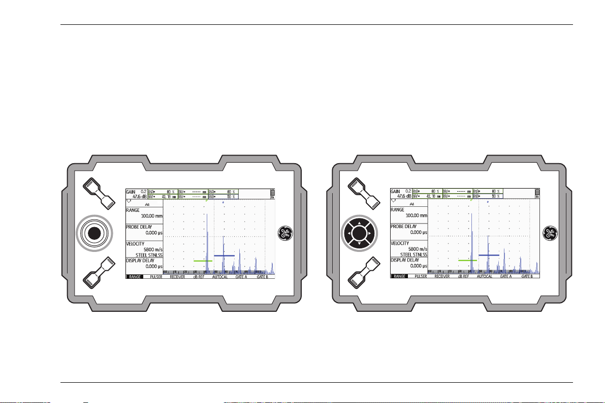
4 Principles of operation Overview of operator's controls
1
3
4
1
2
2
3
4
5
6 7
5
USM Go USM Go+
4.1 Overview of operator's controls
1 Increasing the gain level in increments
2 Decreasing the gain level in increments
3 Operating levels and function groups navigation
4 Function key 1, individually assignable
4-2 Issue 6 (02/2013) USM Go
5 Function key 2, individually assignable
6 Display for representation of A-scan and functions
7 Power key for powering on and off
Page 55

Display screen 4 Principles of operation
4.2 Display screen
A-scan representation
The USM Go has a high-resolution display screen for
the display of the A-scan.
A-scan display in the normal mode
A-scan display in the zoom mode
The gain and the adjusted dB step value are shown in
the top left corner of the display screen. The access to
all other instrument functions is disabled in the zoom
mode of the A-scan display.
Toggling the A-scan display mode
To toggle between the normal and the zoomed A-scan
display mode, shortly press the joystick (USM
the center key of the keypad (USM
Go+) once.
Go) or
USM Go Issue 6 (02/2013) 4-3
Page 56

4 Principles of operation Display screen
Functions on the display screen
Function groups
The names of the seven function groups are shown at
the bottom of the display screen. The currently selected
function group is highlighted.
First operating level (A-scan):
Second operating level (settings):
Functions
On the first operating level, the functions of the currently
selected function group are shown on the left of the dis
play screen, next to the A-scan.
The functions are hidden in the zoomed A-scan display
mode; no operation is possible in this case.
-
4-4 Issue 6 (02/2013) USM Go
Page 57

Display screen 4 Principles of operation
Note
Gain
The current gain value and the adjusted dB step value
are always displayed in the top left corner of the screen.
Measurement line
The measurement line on top of the A-scan shows seven different measurement readings. One reading can be
displayed in enlarged mode in a box on the far right. The
readings for the individual boxes are user selectable
(
see Section Configuring the measurement line,
page 5-59).
One or four measurement readings can be displayed in
enlarged mode. The number of the other boxes of the
measurement line is then reduced (
larged display of reading, page 5-62).
see Section En-
In addition to the measurement reading, the measuring
point (peak or flank) is displayed with a symbol in sound
path measurements:
^ = measuring point Peak
/ = measuring point Flank
Examples:
SA^ = sound path within gate A, at the measuring point
Peak
SA/ = sound path within gate A, at the measuring point
Flank
The measuring point for amplitude is marked
for the corresponding gate bar at the top
edge of the display by a triangle pointing up
wards in the color of the gate, the measuring
point for distance is marked by a triangle
pointing downwards.
-
USM Go Issue 6 (02/2013) 4-5
Page 58

4 Principles of operation Display screen
Status display icons
To the left of the A-scan, below the measurement line,
there is an area for various status displays. The status
display icons inform about active functions and certain
settings (
the beginning of the present operating manual).
see Section Status display icons, page 0-7 at
Alarms
You can display an alarm signal in the form of a virtual
LED in the far right box on top of the A-scan (
tion LARGE (alarm signal), page 5-64).
When an alarm is triggered, the color of the alarm signal
changes from green to red.
see Sec-
4-6 Issue 6 (02/2013) USM Go
Page 59

Navigation and function keys 4 Principles of operation
Note
4.3 Navigation and function keys
Navigation
A joystick is used in the USM Go for navigation, for
changing settings, and for selecting adjustment values.
These functions are carried out by means of five keys in
the keypad of the USM
pad correspond to the movement of the joystick in the
corresponding direction, and pressing the center key
corresponds to pressing the joystick.
The navigation is used
● for toggling between the operating levels,
● for selecting function groups,
● for selecting and setting functions,
● for selecting the zoom mode of A-scan display
Go+. The arrow keys in the key-
Function keys
Two key groups consisting of two function keys each are
arranged next to the display screen.
The two upper function keys are used for changing the
gain and turning the function AUTO
Key combinations, page 4-8).
The two lower function keys are used
● for changing values or settings,
● for selecting options,
● for triggering user-assigned functions (see Chapter
5.3 Assignment of function keys, page 5-8).
You can change many values either by
means of the navigation (small increments)
or by means of the lower function keys (large
increments).
80 on (see Section
USM Go Issue 6 (02/2013) 4-7
Page 60

4 Principles of operation Navigation and function keys
Key combinations
You can carry out some functions by means of key combinations. To achieve this, you have to press several
keys at the same time (
ator's controls, page 4-2).
Function Keys
HOME
Function key 1 + function key 2
see Section Overview of oper-
AUTO 80
UPDATE
RESET
Increase gain + decrease gain
Decrease gain + function key 2 + Power key
Increase gain + function key 2 + Power key
Power key
The key for powering the instrument on and off is located on the instrument side, next to the probe connectors.
4-8 Issue 6 (02/2013) USM Go
Page 61

Operational concept 4 Principles of operation
4.4 Operational concept
Operating levels
The USM Go is an easy-to-use instrument. It has two
operating levels between which you can toggle by
pressing the joystick (USM
(USM
Go+).
The first operating level shows the A-scan and is used
during normal operation.
It contains seven function groups for the settings during
normal operation.
The second operating level contains all functions for the
instrument configuration. This is where you will also find
functions for saving and printing, for data management
using the data logger, and for special applications, e.g.
software updates.
Go) or the center key
Selecting and setting functions
Shown below the A-scan are the seven function groups
which you can directly select using the navigation. The
name of the currently selected function group is high
lighted and the corresponding four functions are displayed on the left, next to the A-scan.
You can likewise directly select the individual functions
using the navigation.
If a function is selected, the name of the function group
is marked red. You can then change the value using the
navigation or the function keys.
-
USM Go Issue 6 (02/2013) 4-9
Page 62

4 Principles of operation Operational concept
Note
Coarse and fine adjustment of functions
You can choose between coarse and fine adjustment
for some functions.
The fine adjustment is made using the navigation. The
fastness of change is influenced by the movement of the
joystick during this (e.g. for the function VELOCITY).
You can lock the joystick in the USM Go. Any
changes to the adjustments using the joy
-
stick are then no longer possible (see Section Locking the joystick, page 5-76).
Use the lower function keys to make the coarse adjustment. The value will then change either in large increments (e.g. for the function RANGE) or you can choose
from a series of factory-saved values (e.g. for the func
-
tion VELOCITY)
During the fine adjustment, the name of the function is
displayed in lower-case letters (range), whereas it is
displayed in capital letters during the coarse adjustment
(RANGE).
As long as a function is selected, you can only change
the corresponding value but you cannot toggle between
the function groups. To toggle between the function
groups, you have to first select a function group again
using the navigation (the name is highlighted).
4-10 Issue 6 (02/2013) USM Go
Page 63

Operational concept 4 Principles of operation
Note
Function HOME
You can or must select the function HOME in various
cases (e.g. to confirm certain settings). To do this, press
the function keys at the same time (
view of operator's controls, page 4-2).
You can assign the function HOME to one of
the function keys (
of function keys, page 5-8).
Choosing the start value
You can use the function HOME for some functions to
quickly choose the start value of the adjustment range.
To do this, press the two lower function keys at the
same time after selecting the function. In this way, you
can e.g. set the value of the function DISPLAY DELAY
to 0.000 µs.
see Section Over-
see Section Assignment
This quick adjustment option is available for the following functions:
Function Function group
PROBE DELAY RANGE
DISPLAY DELAY RANGE
REJECT RECEIVER
USM Go Issue 6 (02/2013) 4-11
Page 64

4 Principles of operation Operational concept
Note
Activating functions
You have usually two options for choosing functions, for
triggering actions, or for changing settings on the sec
ond operating level:
● using the function keys directly after selecting a function,
● using the function keys or the navigation after activating a function.
The direct change of settings or functions is
disabled for some functions and, in any case,
you must activate the function first before
you can change any settings. This is the
case e.g. for the function DIRECTORY for
selecting a directory on the SD memory card.
-
Example
– Switch over to the second operating level.
– In the function group EVAL, select the function MAG-
NIFY GATE.
Option 1:
– Press the function keys to directly choose the gate for
the magnify gate function.
Option 2:
– Press the joystick (USM Go) or the center key of the
keypad (USM
Go+) briefly to activate the function
MAGNIFY GATE. The currently selected setting is
highlighted.
– After that, change the setting using either the naviga-
tion or the function keys.
– After changing the setting, press the joystick
(USM
Go) or the center key of the keypad
(USM
Go+) briefly again to deactivate the function.
You can then use the navigation again to switch over
to another function.
4-12 Issue 6 (02/2013) USM Go
Page 65

Important default settings 4 Principles of operation
4.5 Important default settings
Language setting
Use the function LANGUAGE (function group
CONFIG1 on the second operating level) to choose the
language for the displayed texts.
The following languages are available:
● Bulgarian ● Chinese ● German
● English ● Finnish ● French
● Italian ● Japanese ● Dutch
● Norwegian ● Polish ● Portuguese
● Romanian ● Russian ● Swedish
● Spanish ● Czech ● Hungarian
– Switch over to the second operating level.
– In the function group CONFIG1, select the function
LANGUAGE.
– Press the function keys to choose the required lan-
guage. The language changes immediately.
USM Go Issue 6 (02/2013) 4-13
Page 66

4 Principles of operation Important default settings
Units setting
You can use the function UNITS (function group
CONFIG1 on the second operating level) to select the
required units (mm, in, or µs). You can change the units
any time. All values are adjusted accordingly.
– Switch over to the second operating level.
– In the function group CONFIG1, select the function
UNITS.
Press the function keys to choose the required units.
Decimal separator
You can choose the decimal separator mark. All data
are displayed and saved using the selected decimal
separator.
– Switch over to the second operating level.
– In the function group CONFIG1, select the function
DECIMAL.
Press the function keys to choose the required setting.
4-14 Issue 6 (02/2013) USM Go
Page 67

Important default settings 4 Principles of operation
ATTENTION
Date format, Date, and Time
The date is saved together with the inspection results.
You can set the date format, the date, and the time us
ing the corresponding functions of the function group
CONFIG1 on the second operating level.
In view of a correct documentation, always
make sure that you are using the correct date
and the correct time. Remember to turn the
clock during the change from winter time to
summer time.
– Switch over to the second operating level.
– In the function group CONFIG1, select the function
DATE FORMAT.
– Press the function keys to change the date format.
The time format is changed together with the date for
mat.
– Select the function DATE.
– Press the joystick (USM Go) or the center key of the
keypad (USM
Go+) to change the setting. The first
value (day, month, or year) is highlighted.
– Use the navigation to change the highlighted value
and switch over to the next value.
– Change the other values in the same way.
-
– Finally, press the joystick (USM Go) or the center key
of the keypad (USM
Go+) to close the setting. The
new values apply immediately.
– Select the function TIME.
– Change the time in the same way as you did previ-
ously for the date.
– Finally, press the joystick (USM Go) or the center key
of the keypad (USM
Go+) to close the setting. The
new values apply immediately.
-
USM Go Issue 6 (02/2013) 4-15
Page 68

4 Principles of operation Default settings of the display
Selecting the instrument orientation
You can configure the instrument for right-handed or
left-handed operation (referred to the probe). The
screen display is then rotated through 180°, the func
tions of navigation and function keys are adjusted accordingly.
– Switch over to the second operating level.
– In the function group CONFIG1, select the function
ORIENTATION.
4.6 Default settings of the display
The USM Go is equipped with a high-resolution color
display. You can optimize the display according to your
own viewing habits and to the operating environment.
Selecting the color scheme
-
– Press the function keys to choose the required orien-
tation.
4-16 Issue 6 (02/2013) USM Go
Page 69

Default settings of the display 4 Principles of operation
Note
You can choose one of four color schemes using the
function COLOR (function group CONFIG1 on the sec
ond operating level). The color scheme determines the
color of all displays and of the background. You can set
the color of the A-scan separately (please see the sec
tion below).
All color schemes are suitable for indoor use.
For outdoor use, we recommend Scheme 3
and Scheme 4.
– Switch over to the second operating level.
– In the function group CONFIG1, select the function
COLOR.
– Press the function keys to select the required color
scheme.
Selecting the A-scan color
-
-
You can choose the color of the A-scan using the function
A-SCAN COLOR (function group CONFIG1 on the sec
ond operating level). The color options depend on the selected color scheme (see Section Selecting the color
scheme, page 4-16).
– Switch over to the second operating level.
– In the function group CONFIG1, select the function
A-SCAN COLOR.
-
– Press the function keys to choose the required color
for the A-scan.
USM Go Issue 6 (02/2013) 4-17
Page 70

4 Principles of operation Default settings of the display
Note
Selecting the grid
Using the function GRID (function group CONFIG1 on
the second operating level), you can choose a grid for
the A-scan. Two grids, each with and without a ruler at
the bottom edge of the display, are available as options.
– Switch over to the second operating level.
– In the function group CONFIG1, select the function
GRID.
– Press the function keys to choose the required grid
for the A-scan.
Setting the brightness
To set the brightness of the display, use the function
BRIGHTNESS (function group CONFIG1 on the second
operating level). You can choose a value from 1 to 10.
A high brightness value increases the power
consumption, due to which the operating
time is reduced in battery operation.
4-18 Issue 6 (02/2013) USM Go
Page 71

Saving the settings 4 Principles of operation
Note
– Switch over to the second operating level.
– In the function group CONFIG1, select the function
BRIGHTNESS.
– Press the function keys to select the required value.
You can extend the operating time by means
of the power saver function (
Power saving mode, page 5-79).
see Section
4.7 Saving the settings
You can save the current instrument settings to a file on
the SD memory card. The files for the USM
filename extension UGO.
Go have the
USM Go Issue 6 (02/2013) 4-19
Page 72

4 Principles of operation Saving the settings
ATTENTION
– Switch over to the function ACTION and press the
The filename can be up to 14 characters long
for saving data sets. However, only the first 7
characters are shown in the display on top of
the A-scan (
see Section Displaying dataset
name, page 4-22).
Please note this limitation when saving data
sets in order to avoid any confusions be
tween filenames starting with the same character.
function keys to select the function STORE DATA
SET.
– Switch over to the function FILENAME and briefly
press the joystick (USM
keypad (USM
Go+).
Go) or the center key of the
– Use the navigation to choose the option
<NEW
FILE> and briefly press the joystick (USM Go)
or the center key of the keypad (USM
Go+).
– Use the navigation to choose the first character of the
filename.
-
– Use the navigation to switch over to the next item,
and choose the next character.
– Switch over to the second operating level.
– Press the joystick (USM Go) or the center key of the
– In the function group FILES, select the function
DIRECTORY and briefly press the joystick (USM Go)
or the center key of the keypad (USM
Go+). The di-
keypad (USM
try.
Go+) briefly to close the filename en-
rectory of the SD memory card appears.
– Press the function keys to select a directory on the
SD card.
– Press the joystick (USM Go) or the center key of the
keypad (USM
Go+) briefly to choose the selected di-
rectory.
4-20 Issue 6 (02/2013) USM Go
Page 73

Saving the settings 4 Principles of operation
Note
Note
– Switch over to the function ENTER and briefly press
the joystick (USM
(USM
Go+).
Go) or the center key of the keypad
The current instrument settings are saved to the selected directory on the SD memory card under the name entered here.
You can create and delete directories by inserting the SD memory card into the SD card
reader of your PC or by connecting the
USM
Go to a PC via a USB cable (see Sec-
tion USB interface, page 8-3).
Recalling settings
You can recall and use instrument settings saved to the
SD memory card.
You can only recall datasets having the filename extension UGO. Other files on the SD
memory card are not displayed as options.
– Switch over to the second operating level.
– In the function group FILES, select the function
DIRECTORY and briefly press the joystick (USM Go)
or the center key of the keypad (USM
rectory of the SD memory card appears.
– Press the function keys to select a directory on the
SD card.
– Press the joystick (USM Go) or the center key of the
keypad (USM
Go+) briefly to choose the selected di-
rectory.
Go+). The di-
USM Go Issue 6 (02/2013) 4-21
Page 74

4 Principles of operation Saving the settings
Note
– Switch over to the function ACTION and press the
function keys to select the function RECALL DATA
SET.
– Switch over to the function FILENAME and briefly
press the joystick (USM
keypad (USM
Go+).
Go) or the center key of the
– Use the navigation to select the name of the required
dataset.
– Press the joystick (USM Go) or the center key of the
keypad (USM
Go+) briefly. The selection is automat-
ically changed to the function ENTER.
– Press the joystick (USM Go) or the center key of the
keypad (USM
Go+) briefly.
The instrument settings of the selected dataset are recalled and they are immediately active after closing the
recalling process.
Displaying dataset name
-
You can display the filename of the currently recalled instrument settings (dataset name) in the measurement
line on top of the A-scan.
The dataset name can only be displayed in
the box on the far right.
4-22 Issue 6 (02/2013) USM Go
Page 75

Saving the settings 4 Principles of operation
ATTENTION
– Switch over to the second operating level.
– Select the function group EVAL.
– Select the function LARGE.
– Press the function keys to choose the parameter
DSET as value.
– Switch over to the first operating level.
The filename can be up to 14 characters long
for saving data sets (on the second operating
level). However, only the first 7 characters
are shown in the display on top of the A-scan
(on the first operating level).
Please note this limitation when saving data
After recalling the instrument settings, the corresponding filename (dataset name) is displayed in red letters in
sets in order to avoid any confusions be
tween filenames starting with the same character.
-
the measurement line on top of the A-scan in the box on
the far right.
USM Go Issue 6 (02/2013) 4-23
Page 76

4 Principles of operation Saving the settings
4-24 Issue 6 (02/2013) USM Go
Page 77

Operation 5
USM Go Issue 6 (02/2013) 5-1
Page 78

5 Operation Overview of the functions
Note
Note
5.1 Overview of the functions
The functions of the USM Go are combined into function
groups on two operating levels.
– Press the joystick (USM Go) or the center key of the
keypad (USM
tween the two operating levels.
– Use the navigation to select a function or a setting.
– Press the function keys to change a setting.
The gain is always directly available to you by means of
the two keys at the top, next to the display.
You will find an overview of the function groups and their
corresponding functions on the first pages of this oper
ating manual.
Go+) for about 2 seconds to toggle be-
You will find detailed descriptions of how to
use the operator's controls in
ciples of operation.
Chapter 4 Prin-
The first operating level contains seven function groups
in the default view.
When certain functions are activated, other
associated function groups become visible
by navigating upwards. You can return to the
previous view by pressing the center key.
The second operating level contains eight function
groups.
First operating level
Second operating level
-
5-2 Issue 6 (02/2013) USM Go
Page 79

Overview of the functions 5 Operation
Function groups first operating level
RANGE This is where you will find functions required for the basic setting of the signal representation on the
display screen.
PULSER This group is a combination of functions used for setting the pulser.
RECEIVER This group is a combination of functions used for setting the receiver.
dB REF This group contains functions for evaluation. The name and functions of this group vary depending
on the selected evaluation method.
AUTOCAL This is where you will find the functions for the semi-automatic calibration of the instrument.
GATE A In this group, you will find all functions required for setting the gate A.
GATE B In this group, you will find all functions required for setting the gate B.
GATES Only if the option 3B is enabled: All functions for setting the gates A, B, and C.
The function groups GATE A and GATE B are then no longer visible.
USM Go Issue 6 (02/2013) 5-3
Page 80

5 Operation Overview of the functions
Function groups second operating level
FILES This is where you will find functions used for the management of files, test reports, and videos.
EVAL This group is a combination of functions for evaluation methods. In addition, you can configure the
measurement line here (
dB REF This group contains functions for the evaluation method dB Ref. The name and functions of this
group vary depending on the selected evaluation method.
DAC/TCG This group contains the functions for the evaluation method DAC/TCG (option).
DGS This group contains the functions for the evaluation method DGS (option).
AWS D1.1 This group contains the functions for the evaluation method AWS D1.1 (option).
JISDAC This group contains the functions for the evaluation method JISDAC (option).
CNDAC This group contains the functions for the evaluation method CNDAC (option).
see Section Measurement line, page 4-5).
5-4 Issue 6 (02/2013) USM Go
Page 81

Overview of the functions 5 Operation
CONFIG1 This is where you will find various default settings, e.g. language, color, and A-scan display options.
CONFIG2 This is where you will find special functions for the instrument setup for test and measurement
applications.
CONFIG3 This is where you will find additional functions for the instrument setup for test and measurement
applications.
CONFIG4 This group contains functions for the automatic gain control.
DR This group contains all functions for the data logger (option).
USM Go Issue 6 (02/2013) 5-5
Page 82

5 Operation Setting the gain
5.2 Setting the gain
To enable you to set the gain quickly and directly, this
function is always available to you with the two keys at
the top, next to the display screen.
You can use the gain to adjust the sensitivity necessary
for making echoes from reflectors to be detected visible
on the display screen at the required height.
– Press the upper key to increase the gain. The current
gain is displayed in the top left corner of the display
screen.
– Press the lower key to decrease the gain.
Setting the dB increment of gain
By pressing the keys, you will always set the gain by a
certain dB increment. You can define this dB increment.
5-6 Issue 6 (02/2013) USM Go
Page 83

Setting the gain 5 Operation
Note
The following settings are possible:
● LOCK (locked)
● 0.2 dB
● 0.6 dB
● 1.0 dB
● 2.0 dB
● 6.0 dB
● 0.2 … 60.0 dB
The setting LOCK locks the gain thus preventing its adjustment by mistake.
– Switch to the second operating level.
– In the function group CONFIG2, select the function
dB STEP.
– Press the function keys to choose the required dB in-
crement.
You can define the dB increment of the seventh level using the function USER GAIN STEP.
You can set the display range by coarse adjustment
steps or by fine adjustment (
see Section Coarse and
fine adjustment of functions, page 4-10).
– Select the function USER GAIN STEP.
– Set the user gain step by means of the function keys
or using the navigation.
USM Go Issue 6 (02/2013) 5-7
Page 84

5 Operation Assignment of function keys
5.3 Assignment of function keys
You can assign various functions to the two function
keys at the bottom, next to the display screen, so that
you will be able to trigger these functions any time with
out switching the operating level.
Each one of the two function keys can have two function
assigned to it, one of which is triggered by briefly press
ing the key, whereas the other one is triggered by pressing the key for a longer time (approx. 2 seconds). All in
all, this means that you can assign four different func
tions to the two function keys.
-
The following settings are possible:
● NONE (no function selected)
● FREEZE (see page 5-68)
● JOYSTICK LOCK (see page 5-76)
● COPY (see page 6-2)
● AUTO80 (see page 5-92)
● MAGNIFY GATE (see page 5-65)
● dB STEP (see page 5-6)
● RECALL DATASET (see page 4-21)
● ORIENTATION (see page 4-16)
● ENVELOPE (see page 5-83)
● HOME (see page 4-8)
● ANGLE+
-
● ANGLE-
● BW GAIN+ (see page 5-82)
-
● BW GAIN- (see page 5-82)
5-8 Issue 6 (02/2013) USM Go
Page 85

Assignment of function keys 5 Operation
– Switch to the second operating level.
– In the function group CONFIG2, select the function
FUNCTION
1 to assign functions to the upper func-
tion key.
– Activate the function (see Section Activating func-
tions, page 4-12). The upper option is selected and
you can now choose the function for the brief key
press.
– Use the navigation to choose the required function for
the brief key press.
– Press one of the function keys to choose the function
for the long key press. The selection changes to the
lower option and the name of the function changes to
(HOLD)func
1.
– Press the function keys to choose the function for the
long key press.
– Finally, deactivate the function (HOLD)func 1.
– Switch to the function FUNCTION 2 to assign func-
tions to the lower function key.
USM Go Issue 6 (02/2013) 5-9
Page 86

5 Operation Setting the display range (function group RANGE)
Note
5.4 Setting the display range (function group RANGE)
For an exact adjustment of the sound velocity and the probe delay, please start by reading Chapter 5.8 Calibrating the USM Go,
page 5-29.
You need the function group RANGE for the basic setting of the display range. The display range must be adjusted to the sound velocity used (function VELOCITY)
and to the probe used (function PROBE DELAY).
– Switch to the first operating level.
– Select the function group RANGE.
5-10 Issue 6 (02/2013) USM Go
Page 87

Setting the display range (function group RANGE) 5 Operation
Note
Note
RANGE
You can use the function RANGE to set the range (the
display range) for making measurements.
You can set the display range by coarse adjustment
steps or by fine adjustment (
fine adjustment of functions, page 4-10).
The adjustment range is 0.5 … 20000.00 mm.
The adjustment range for display range depends on the sound velocity setting and on
the frequency range setting (function FRE
QUENCY in the function group RECEIVER).
– Select the function RANGE.
– Set the required display range by means of the func-
tion keys or using the navigation.
– Press the two function keys at the same time to quick-
ly adjust an average value (254.00 mm).
see Section Coarse and
-
PROBE DELAY
Every probe is equipped with a delay line between the
transducer and the coupling face. The sound pulse must
first pass through this delay line before it can enter the
test object. You can compensate for this influence of the
delay line in the probe in the function PROBE DELAY.
You can set the probe delay by coarse adjustment steps
or by fine adjustment (
justment of functions, page 4-10).
The adjustment range is 0 … 1000.000 µs.
If the value for the probe delay is not known,
please read
USM Go, page 5-29 to determine this value.
– Select the function PROBE DELAY.
– Set the probe delay by means of the function keys or
using the navigation.
– Press the two function keys at the same time to set
the value to zero.
see Section Coarse and fine ad-
Chapter 5.8 Calibrating the
USM Go Issue 6 (02/2013) 5-11
Page 88

5 Operation Setting the display range (function group RANGE)
Note
ATTENTION
VELOCITY
Please always make sure that the setting of
If µs are selected as units, the function VE-
LOCITY is deactivated for safety reasons
and it does not appear on the display screen.
You can use the function VELOCITY to set the sound
velocity in the test object.
You can choose between different materials and their
sound velocities. The additional information TR. and
TRANS refer to the sound velocities in transverse wave
excitation mode. In longitudinal wave excitation mode,
the material name remains without additional informa
-
tion.
If you deviate from a specified material velocity when
using the navigation, the material name is automatically
replaced by the information CUSTOM. You can set the
sound velocity by coarse adjustment steps or by fine ad
justment (see Section Coarse and fine adjustment of
functions, page 4-10).
– Select the function VELOCITY.
– Set the sound velocity by means of the function keys
or using the navigation.
-
the function VELOCITY is correct. The USM
Go calculates all range and distance indica
tions on the basis of the value adjusted here.
-
The adjustment range is 250 … 16000 m/s.
5-12 Issue 6 (02/2013) USM Go
Page 89

Setting the display range (function group RANGE) 5 Operation
DISPLAY DELAY
You can use this function to choose whether to display
the adjusted display range (for example 250 mm) start
ing from the surface of the test object or in a section of
the test object starting at a later point. This allows you to
shift the complete screen display and consequently also
the display zero.
For example, if the display should start from the surface
of the test object, you have to adjust the value 0 for DIS
PLAY DELAY.
You can set the display delay by coarse adjustment
steps or by fine adjustment (
see Section Coarse and
fine adjustment of functions, page 4-10).
The adjustment range is -15.000 … 3500.000 µs.
– Select the function DISPLAY DELAY.
– Set the sound velocity by means of the function keys
or using the navigation.
– Press the two function keys at the same time to set
the value to zero.
-
-
USM Go Issue 6 (02/2013) 5-13
Page 90

5 Operation Setting the pulser (function group PULSER)
5.5 Setting the pulser (function group PULSER)
You will find all functions for setting the pulser in the
function group PULSER.
– Switch to the first operating level.
– Select the function group PULSER.
VOLTAGE (pulser voltage)
You can use the function VOLTAGE to set the pulser
voltage.
The following settings are possible:
● HIGH – high voltage
● LOW – low voltage
The setting HIGH is recommended for all tests in which
maximum sensitivity is important, e.g. for the detection
of small flaws. Choose the setting LOW for broadband
probes or if narrow echoes are required (better lateral
resolution).
Square-wave pulser
If your USM Go is equipped with a square-wave pulser
(option) and if the square-wave pulser is chosen as
pulser type (
page 5-75), then you can set the pulser voltage within
the range of 120 … 300 V in steps of 10 V. Instead of
the function ENERGY, the function WIDTH is then avail
able.
see Section Selecting the pulser type,
-
5-14 Issue 6 (02/2013) USM Go
Page 91

Setting the pulser (function group PULSER) 5 Operation
ATTENTION
Note
ENERGY
Use the data sheet for your probe to check
which maximum voltage is allowed to be ap
plied.
The pulser voltage and the pulse width can
be automatically limited, depending on the
pulse repetition frequency (
see Section PRF
MODE (pulse repetition frequency),
page 5-17) setting. This function helps to
avoid heat accumulations in the pulser electronics.
– Select the function VOLTAGE.
– Press the function keys to choose the required pulser
voltage.
You can use the function ENERGY to set the penetration or sound energy.
The following settings are possible:
● HIGH – high energy
● LOW – low energy
The setting HIGH is recommended for all tests in which
maximum sensitivity is important, e.g. for the detection
of small flaws. Choose the setting LOW for broadband
probes or if narrow echoes are required (better lateral
resolution).
– Select the function ENERGY.
– Press the function keys to choose the required set-
ting.
USM Go Issue 6 (02/2013) 5-15
Page 92

5 Operation Setting the pulser (function group PULSER)
Note
WIDTH
This function is only available if the option square-wave
pulser is chosen as pulser type (
see Section Selecting
the pulser type, page 5-75).
You can use the function WIDTH to adjust the pulse
width for the square-wave pulser. You can adjust a val
ue within the range of 30 … 500 ns (nanoseconds) in
steps of 10
ns.
The following equation produces an approximation for
the suitable pulse width:
Nominal width in nanoseconds
= 500/probe frequency in MHz
For example, the equation for a 2.25 MHz probe results
in:
Nominal width in nanoseconds
= 500/2.25 ns = 222 nanoseconds
The pulser voltage and the pulse width can
be automatically limited, depending on the
pulse repetition frequency (
see Section PRF
MODE (pulse repetition frequency),
-
page 5-17) setting. This function is used for
limiting the signal loss.
– Select the function WIDTH.
– Press the function keys to select the required value.
5-16 Issue 6 (02/2013) USM Go
Page 93

Setting the pulser (function group PULSER) 5 Operation
DAMPING
This function is used for matching the probe. By setting
the damping of the probe oscillating circuit you can vary
the height, width, and resolution of the echo display.
The following settings are possible:
● 1000 Ohm
low damping, the echoes become higher and broader.
● 50 Ohm
reduces the echo height but produces narrower
echoes with a higher resolution.
– Select the function DAMPING.
– Press the function keys to select the required value.
PRF MODE (pulse repetition frequency)
The pulse repetition frequency indicates the number of
times an initial pulse is triggered per second. You can
decide whether you need the highest possible PRF val
ue or whether you are satisfied with a low value. You
have three fixed steps and one user-variable step avail
able for the adjustment.
The larger your test object, the smaller PRF values are
needed to avoid phantom echoes. However, the A-scan
update rate becomes lower in the case of smaller PRF
values; high values are therefore required if a test object
should be scanned fast.
The best way to determine the suitable PRF value is by
experimenting: Start from the highest step and reduce
the value until there are no more phantom echoes.
-
-
USM Go Issue 6 (02/2013) 5-17
Page 94

5 Operation Setting the pulser (function group PULSER)
Note
The following settings are possible:
● AUTO LOW 400 Hz
● AUTO MED 1000 Hz
● AUTO HIGH 1500 Hz
● MANUAL
You can detect and avoid phantom echoes
by means of the optional function phantom
PRF (
see Section Phantom echo detector,
page 5-58).
– Select the function PRF MODE.
– Press the function keys to select the required value.
– If you have selected MANUAL, set the required value
using the navigation.
5-18 Issue 6 (02/2013) USM Go
Page 95

Setting the receiver (function group RECEIVER) 5 Operation
5.6 Setting the receiver (function group RECEIVER)
You will find all functions for setting the receiver in the
function group RECEIVER.
– Switch to the first operating level.
– Select the function group RECEIVER.
FREQUENCY
In this function, you can set the frequency of the receiver
according to the frequency of your probe.
The following settings are possible:
● BROADBAND
● 1 - 5 MHz
● 2 MHz
● 2.25 MHz
● 4 MHz
● 5 MHz
● 10 MHz
● 13 MHz
● 15 MHz
– Select the function FREQUENCY.
– Press the function keys to select the required value.
USM Go Issue 6 (02/2013) 5-19
Page 96

5 Operation Setting the receiver (function group RECEIVER)
RECTIFY
You can use the function RECTIFY to select the rectification mode of the echo pulses according to your application.
The following settings are possible:
● FULLWAVE
All half-waves are displayed above the base line on
the screen.
● POS HALFWAVE
Only positive half-waves are displayed above the
base line on the screen.
● NEG HALFWAVE
Only negative half-waves are displayed above the
base line on the screen.
● RF (radio frequency)
There is no rectification. Both positive and negative
wave portions are displayed with true amplitude.
– Select the function RECTIFY.
– Press the function keys to choose the required set-
ting.
DUAL (pulser-receiver separation)
You can use the function DUAL to activate the pulserreceiver separation (
probe, page 3-9).
● OFF
Single-element operation; the probe connector sockets are connected in parallel.
● ON
Dual mode for using dual-element probes; one probe
connector is connected to the amplifier input, the ini
tial pulse is applied to the other probe connector.
● THROUGH
Through-transmission mode for using two separate
probes; the receiver is connected to one probe con
nector and the pulser is connected to the other. As
the sound wave passes through the test object only
once in through-transmission mode, all range and
wall thickness measurement functions are adjusted
accordingly.
– Select the function DUAL.
– Press the function keys to choose the required set-
ting.
see Chapter 3.3 Connecting a
-
-
5-20 Issue 6 (02/2013) USM Go
Page 97

Setting the receiver (function group RECEIVER) 5 Operation
ATTENTION
REJECT
You can use the function REJECT to suppress unwanted echo indications, e.g. structural noise from the test
object.
The height in % indicates the minimum height that the
echoes must attain in order for them to be displayed on
the screen at all. The reject setting cannot be higher
than 80 %.
You should handle this function with great
caution as it may of course happen that you
suppress echoes from flaws as well. Many
test specifications expressly forbid using the
reject function.
– Select the function REJECT.
– Press the function keys to select the required value.
USM Go Issue 6 (02/2013) 5-21
Page 98

5 Operation Setting the gates (function groups GATE A and GATE B)
5.7 Setting the gates (function groups GATE A and GATE B)
You will find all functions for setting the gates A and B in
the function groups GATE
– Switch to the first operating level.
– Select the function group GATE A or GATE B.
A and GATE B.
Tasks of the gates
● The gates monitor the area of the test object where
you expect to detect a flaw. If an echo exceeds or falls
below the gate, an alarm signal is output (
Alarms, page 4-6).
● The gates A and B are independent of each other.
Gate
A can also assume the function of an echo start
gate for gate
● The gate chooses the echo for the digital time-offlight and amplitude measurement. The measured
value is displayed in the measurement line (
tion Measurement line, page 4-5).
Display of the gates
The gates are displayed in different colors for easier allocation.
B.
see Section
see Sec-
5-22 Issue 6 (02/2013) USM Go
Page 99

Setting the gates (function groups GATE A and GATE B) 5 Operation
A-START/B-START (starting point of the gate)
You can set the starting point of the gates A or B within
an adjustment range of 0
You can set the value by coarse adjustment steps or by
fine adjustment (
ment of functions, page 4-10).
– Select the function A-START or
B-START.
– Set the required value by means of the function keys
or using the navigation.
see Section Coarse and fine adjust-
… 27940 mm.
A-WIDTH/B-WIDTH (width of the gates)
You can set the width of the gates A or B within an adjustment range of 1.00 … 27940.00 mm.
You can set the value by coarse adjustment steps or by
fine adjustment (
ment of functions, page 4-10).
– Select the function A-WIDTH or
B-WIDTH.
– Set the required value by means of the function keys
or using the navigation.
see Section Coarse and fine adjust-
USM Go Issue 6 (02/2013) 5-23
Page 100

5 Operation Setting the gates (function groups GATE A and GATE B)
A-THRESHOLD/B-THRESHOLD (response and measurement threshold of the gate)
You can define the threshold value of the gates A or B
within the range of 5
ing an alarm if this value is exceeded or not reached.
In RF mode, you can additionally set the threshold within the range of –5 … –95 %.
– Select the function A-THRESHOLD or
B-THRESHOLD.
– Press the function keys to select the required value.
… 95 % screen height for trigger-
5-24 Issue 6 (02/2013) USM Go
 Loading...