

Page 1
GE
Sensing & Inspection Technologies
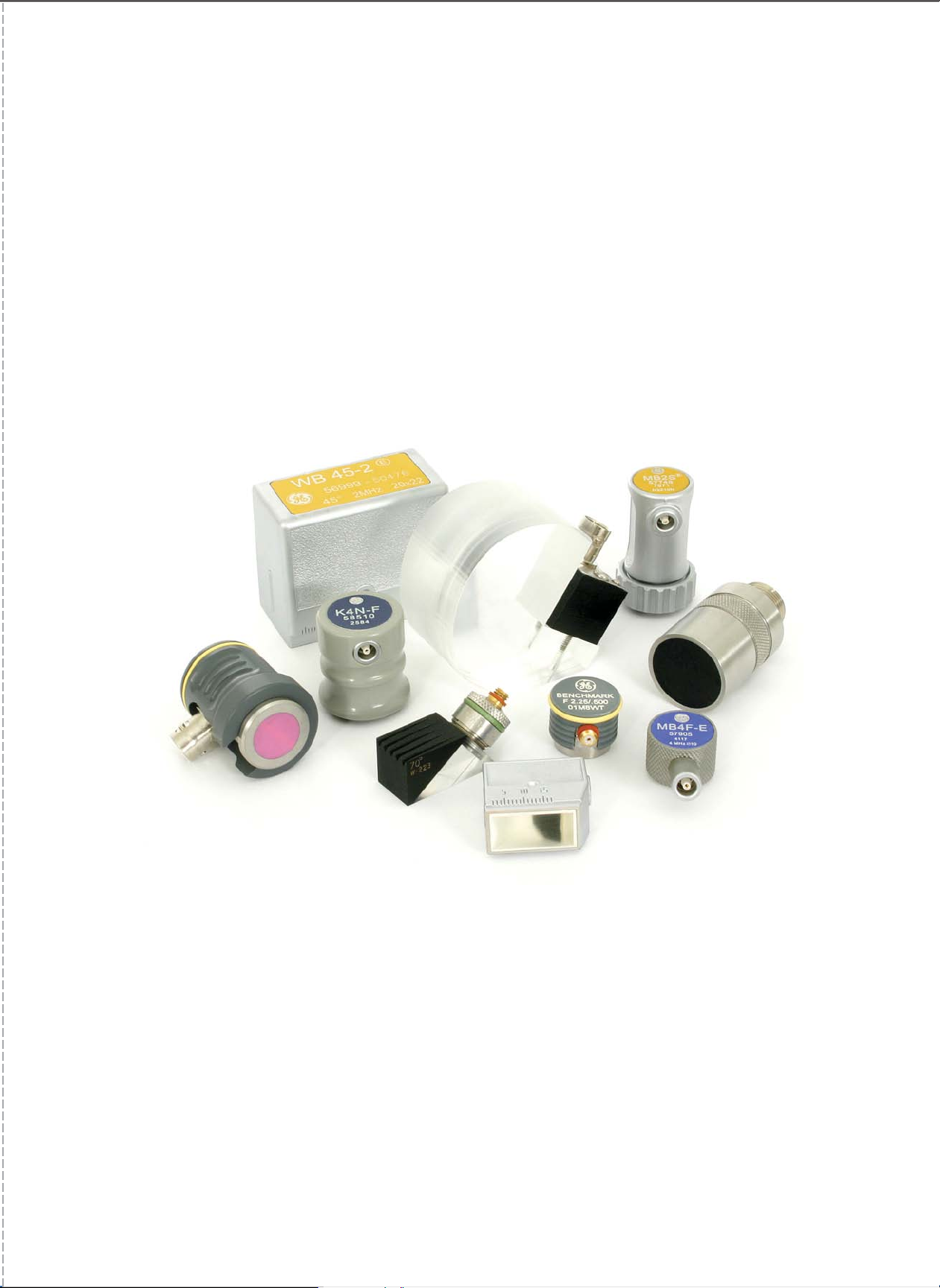
Ultrasonic Transducers
For Flaw Detection and Sizing
gg
Page 2

www.gesensinginspection.com
imagination at work
TÜV
Rheinland
Product Safety
©2008 GE. All rights reserved.
GEIT-20117EN (04/08)
e
i
n
h
l
R
a
n
V
d
Ü
T
o
.
f
c
n
N
I
o
,
r
CUS
a
t
c
h
i
r
A
e
m
Page 3

1
Table of Contents
Transducer Selection Criteria and Performance 2
General Information—Contact Inspection and Immersion Methods . . . . . . . . . . . . . . . . . . . . . . . . . . . . . . . . . . . . . . . . . . . . . . . . . .2
Transducer Selection Criteria—European Standards . . . . . . . . . . . . . . . . . . . . . . . . . . . . . . . . . . . . . . . . . . . . . . . . . . . . . . . . . . . . . . . .3
Transducer Selection Criteria—North American Standards . . . . . . . . . . . . . . . . . . . . . . . . . . . . . . . . . . . . . . . . . . . . . . . . . . . . . . . . . .4
Contact Transducers 5
Straight Beam Contact Transducers, Protective Face . . . . . . . . . . . . . . . . . . . . . . . . . . . . . . . . . . . . . . . . . . . . . . . . . . . . . . . . . . . . . . .5
European
North American
Straight Beam Contact Transducers, Wear Resistant . . . . . . . . . . . . . . . . . . . . . . . . . . . . . . . . . . . . . . . . . . . . . . . . . . . . . . . . . . . . . . .8
European
North American
Straight Beam Contact Transducers, Delay Line . . . . . . . . . . . . . . . . . . . . . . . . . . . . . . . . . . . . . . . . . . . . . . . . . . . . . . . . . . . . . . . . . . .12
European
North American
Straight Beam Contact Transducers, Dual Element (TR) . . . . . . . . . . . . . . . . . . . . . . . . . . . . . . . . . . . . . . . . . . . . . . . . . . . . . . . . . . . .15
European
North American
Angle Beam Transducers—Large Sizes . . . . . . . . . . . . . . . . . . . . . . . . . . . . . . . . . . . . . . . . . . . . . . . . . . . . . . . . . . . . . . . . . . . . . . . . . . . .18
European
North American
Angle Beam Transducers—Small Sizes . . . . . . . . . . . . . . . . . . . . . . . . . . . . . . . . . . . . . . . . . . . . . . . . . . . . . . . . . . . . . . . . . . . . . . . . . . . .22
European
North American
Angle Beam Transducers—Dual Element (TR) . . . . . . . . . . . . . . . . . . . . . . . . . . . . . . . . . . . . . . . . . . . . . . . . . . . . . . . . . . . . . . . . . . . . . .28
Immersion Transducers 31
European . . . . . . . . . . . . . . . . . . . . . . . . . . . . . . . . . . . . . . . . . . . . . . . . . . . . . . . . . . . . . . . . . . . . . . . . . . . . . . . . . . . . . . . . . . . . . . . . . . . . . . . .32
North American . . . . . . . . . . . . . . . . . . . . . . . . . . . . . . . . . . . . . . . . . . . . . . . . . . . . . . . . . . . . . . . . . . . . . . . . . . . . . . . . . . . . . . . . . . . . . . . . .33
Transducers for Specific Applications 35
Special Application Transducers . . . . . . . . . . . . . . . . . . . . . . . . . . . . . . . . . . . . . . . . . . . . . . . . . . . . . . . . . . . . . . . . . . . . . . . . . . . . . . . . . .35
Phased Array Transducers . . . . . . . . . . . . . . . . . . . . . . . . . . . . . . . . . . . . . . . . . . . . . . . . . . . . . . . . . . . . . . . . . . . . . . . . . . . . . . . . . . . . . . .36
Transducer Accessories 37
Cables and Adapters . . . . . . . . . . . . . . . . . . . . . . . . . . . . . . . . . . . . . . . . . . . . . . . . . . . . . . . . . . . . . . . . . . . . . . . . . . . . . . . . . . . . . . . . . . . . .37
Couplants . . . . . . . . . . . . . . . . . . . . . . . . . . . . . . . . . . . . . . . . . . . . . . . . . . . . . . . . . . . . . . . . . . . . . . . . . . . . . . . . . . . . . . . . . . . . . . . . . . . . . . .38
Calibration Blocks . . . . . . . . . . . . . . . . . . . . . . . . . . . . . . . . . . . . . . . . . . . . . . . . . . . . . . . . . . . . . . . . . . . . . . . . . . . . . . . . . . . . . . . . . . . . . . . .39
Transducer Kits . . . . . . . . . . . . . . . . . . . . . . . . . . . . . . . . . . . . . . . . . . . . . . . . . . . . . . . . . . . . . . . . . . . . . . . . . . . . . . . . . . . . . . . . . . . . . . . . . .40
Transducer Certification 41
Tables and Formulas 43
Page 4
2
Transducer Selection Criteria and Performance
General Information
The ultrasonic transducers in this catalog are divided into two
general categories, Contact and Immersion.
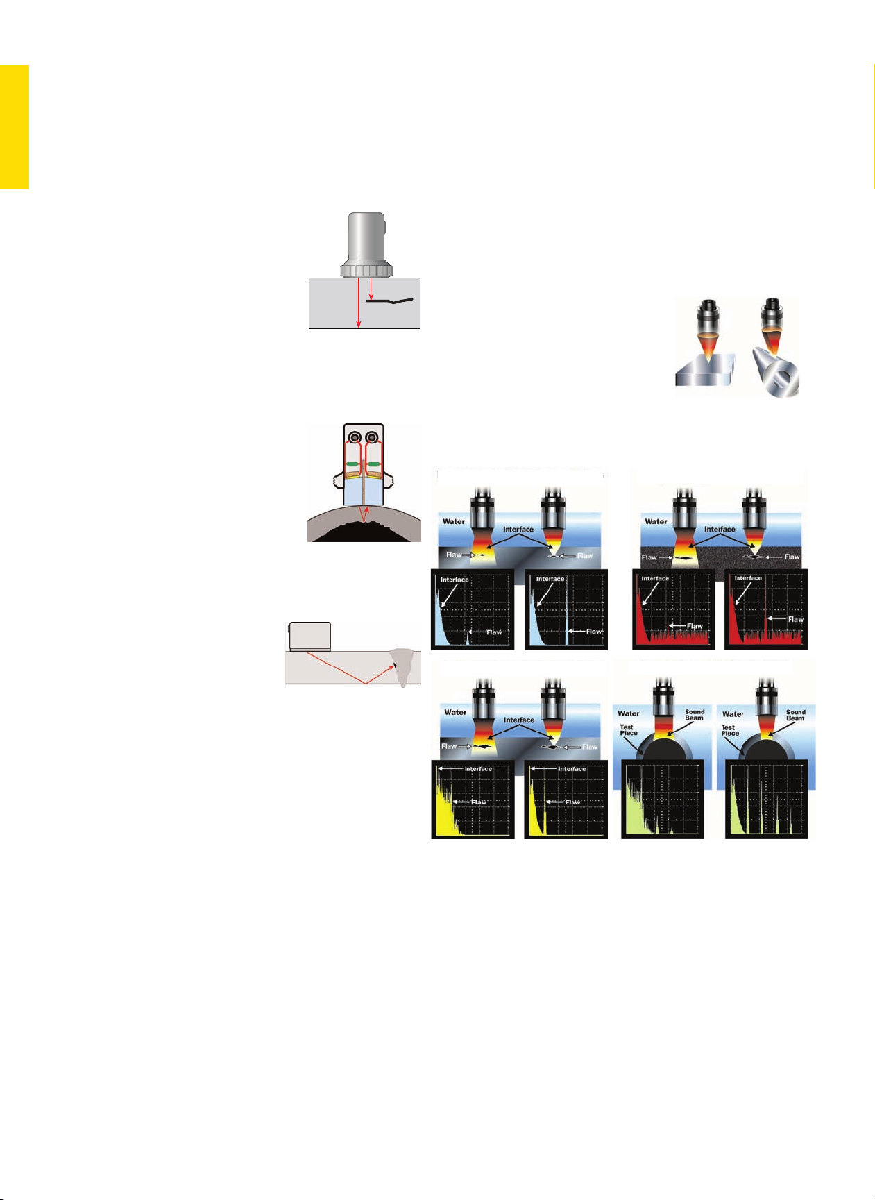
Transducers for the Contact
Inspection Method
Straight Beam—Single Element
• Parts with regular geometry and
relatively smooth contact surface
• Flat or curved contact surface
• Flaw or backwall parallel to surface or
detectable with beam normal to surface
• Preferred for penetration of thick
sections
• Delay line types improve near surface
resolution
• Requires couplant layer, typically a gel, oil, or paste
• Typically used for manual inspection
Straight Beam—Dual Element (TR)
• Transmit and receive elements
separated by crosstalk barrier
• Flaw or backwall parallel to surface or
detectable with beam normal to surface
• Best for thin sections, near surface
resolution
• Requires couplant layer, typically a gel,
oil, or paste
• Typically used for manual inspection
Angle Beam
• Element mounted on integral or
replaceable wedge
• Uses refraction to transmit shear or
longitudinal wave at a
predetermined angle
• Most standard transducers generate
shear waves by mode conversion
• Preferred for parts with inclined
flaws, such as welds
• Available in both single and dual element types
• Requires couplant layer, typically a gel, oil, or paste
• Sometimes used in mechanized or automated testing
Transducers for the Immersion Method
Immersion Transducers
• Acoustically matched for best
efficiency in water
• Suitable for parts with irregular
geometries
• Commonly used in mechanized or
automated testing
• Best method for consistent coupling and reproducible results
• Large parts can be tested using probe holders, bubblers, or
water jets
• Transducers can be focused to improve
results
Focused Immersion Transducers
• Spherical focus forms a point or spot
• Cylindrical focus forms a line
Advantages of Focusing
Spherical (Spot,
Point) Focus
Cylindrical (Line)
Focus
Increase sensitivity to small flaws
Improve near surface resolution
Correct for contoured surfaces
Improve signal-to-noise ratio
Page 5

3
Transducer Selection Criteria—European Standards
For transducers manufactured to European standards, technical and performance information is provided throughout this catalog
based on the definitions below. A comprehensive data sheet is supplied with most flaw detection transducers at no charge.
Description Explanation
Element size D or a x b
Diameter D or length x width a x b of the transducer element. The size of the element strongly affects the shape of the
transmitted sound field. Slight deviations, (e.g., imperfect shape or positions with reduced radiation due to poor bonding)
cause considerable evaluation errors, even when calibrated to a reference flaw.
Nominal frequency f
The mean frequency of all probes of the same type. The frequency has a great influence on the evaluation of reflectors.
Even the shape of the sound field and the reflection behaviour of angled reflectors are strongly dependent on the
frequency. With increasing frequency, the echo height from non-vertically positioned reflectors to the sound beam
decreases. This is why each probe is checked by our Quality Control to see if its frequency coincides with the nominal
frequency, according to the identification label, within very narrow tolerances. This is entered into the probe data sheet.
Bandwidth B
The range of frequencies in the echo pulse whose amplitude, at the most, is 6 dB less than the maximum amplitude.
fo- f
u
B = ------------ X 100%
f
fo= upper, fu= lower frequency limit for a 6 dB drop in amplitude.
With B = 100%, a 4 MHz, probe for example, has an foof 6 MHz and an fuof 2 MHz. Large bandwidths mean shorter echo
pulses, which mean high resolution and a good penetration power, because the lower frequencies of the pulse become less
attenuated than the nominal frequency. At high attenuation, the frequency of reflected signals decreases, compared to the
nominal frequency, as the distance increases. This must be taken into account with flaw evaluation. The bandwidth of each
probe is therefore checked and must, within narrow tolerances, coincide with the mean value of all probes.
Focal distance F
Near field length N
The distance of a small reflector from the probe producing the highest possible echo. Probes are focused in order to detect
small reflectors and produce a high echo amplitude. Focusing is only possible within the near field of the probe.
The near field length N is the focal distance of the unfocused probe which constitutes the sound pressure maximum at the
largest distance from the probe. N is determined by D, c and f.
D
2
eff
D
2
eff
. f
For D >> λ is: N = --------- = -------------
4 λ 4 c
λ = wave length c = sound velocity D
eff
= effective element diameter
Focal point and near field length are the distances with the best sound concentration and reflector recognition. Therefore,
when a probe is selected for a critical test, the flaw expectancy range must be in the focal area or near field length. The
data in the tables refers to steel with the exception of immersion testing in water.
Focal diameter FD
6
Diameter of the sound field in the focal distance or near field length with a 6 dB drop of the echo indication.
F . c 1 F
For D >> λ is: FD 6= ------ = ---- k . D
eff
with k = -----
f - D
eff
4 N
Pulse shape
The presentation of signals, as they are at the instrument input coming from plane reflectors.
Spectrum
Display of all the frequencies in the echo pulse. The frequency amplitudes are shown over the frequency.
Beam angle ß
The angle between the main beam and the normal axis of the test surface.
Page 6
4
Transducer Selection Criteria—North American Standards
For transducers manufactured to North American standards, GE Inspection Technologies offers three
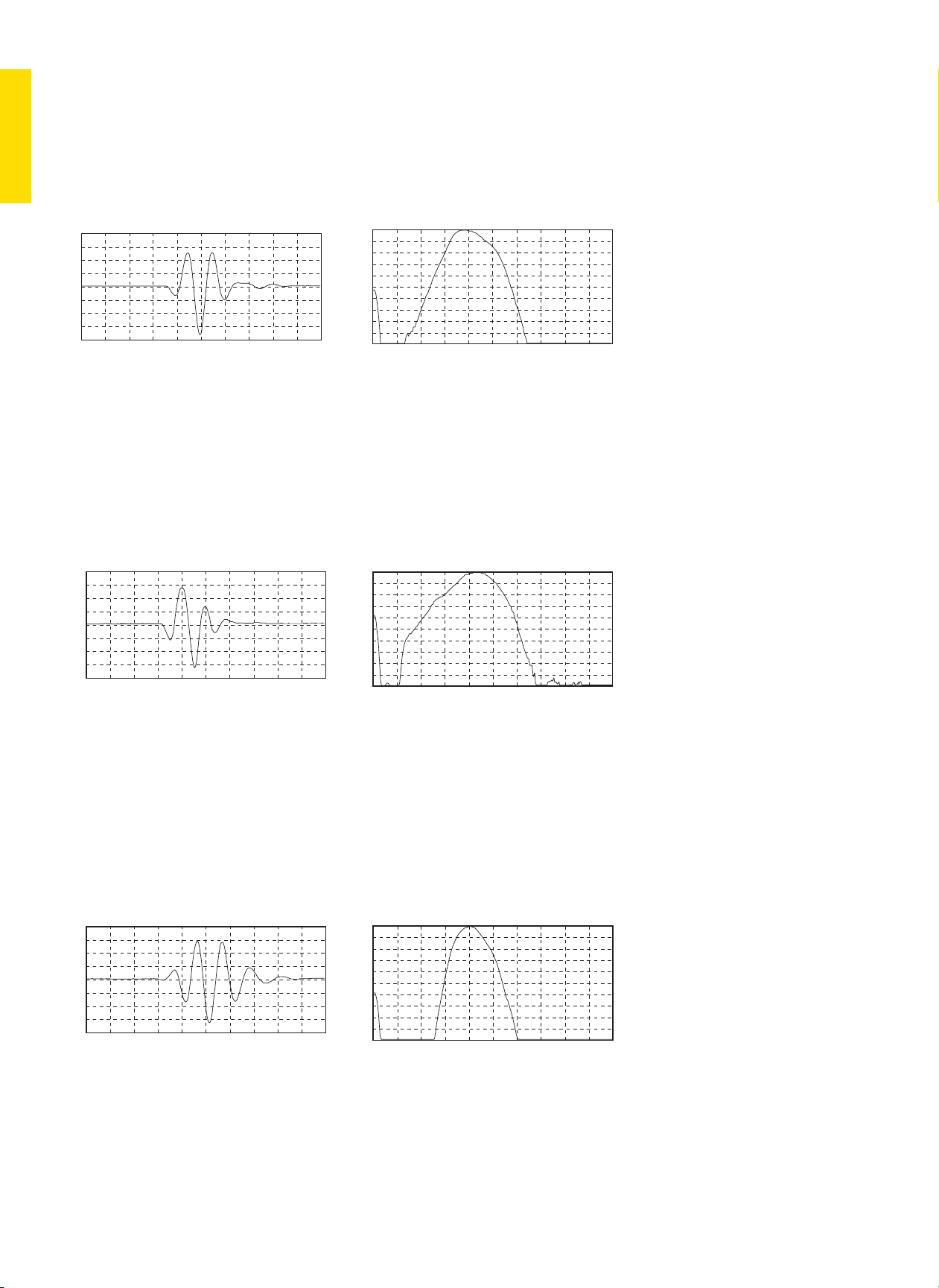
performance ranges: Alpha, Benchmark, and Gamma Series. Waveform and frequency certification,
per ASTM E-1065, are supplied with all flaw detection transducers at no charge.
Alpha Series Features
• Recommended for applications where resolution is the primary consideration.
• Suitable for applications such as thickness measurement and near-surface flaw detection.
• Very short pulse—mechanically damped to the limit of current technology.
• Gain is usually lower than that of the Gamma and Benchmark Series.
• Broadband—typical 6 dB bandwidths range from 50% to 100%.
• Typical Alpha waveforms (right) exhibit one to two full ring cycles, depending on frequency, size and
other parameters.
Benchmark Series Features
• Proprietary BENCHMARK COMPOSITE®(piezocomposite) active elements.
• Penetration in attenuative materials is far superior to conventional transducers.
• High signal to noise on coarse grain metals, fiber reinforced composites, et al.
• Short pulse—resolution usually superior to Gamma Series.
• Gain is usually higher than that of the Gamma and Alpha Series.
• Very broadband—typical 6 dB bandwidths range from 60% to 120%.
• Low acoustic impedance element improves performance of angle beam, delay line, and immersion
probes—excellent match to plastic and water.
Gamma Series Features
• General purpose transducers, recommended for the majority of applications.
• Medium pulse, medium damping—best combination of gain and resolution.
• Matching electrical network ensures maximum gain and optimum waveform for general use.
• Medium bandwidth—typical 6 dB bandwidths range from 30% to 50%.
• Typical Gamma waveform exhibits three to four full ring cycles, depending on frequency, size and
other parameters.
100.0m Volts/div
200.0ns/div
100.0m Volts/div
200.0ns/div
2 dB/div
1.25MHz/div
Real Time
Real Time
Real Time
Spectrum
Spectrum
Spectrum
1.25MHz/div
100.0m Volts/div
2 dB/div
200.0ns/div
2 dB/div
1.25MHz/div
Page 7
5
Straight Beam Contact Transducers, Protective Face
Applications
• General purpose, larger parts with simple geometry
• Forgings, billets
• Plates, bars, square profiles
• Containers, machine components, shells
• Inspection at high temperature with delay line
Features and Benefits
• European models have replaceable membrane:
– Improves coupling on uneven or curved surface
– Extends transducer life.
– Suitable for DGS flaw sizing method
– High temperature delay lines also available
– Lemo 1 (B..S) or Lemo 00 (MB..S) connector, side mount standard, top mount optional
• North American models can be used with three types of protective face:
– Membrane improves coupling on uneven or curved surface.
– Wear cap extends transducer life indefinitely when replaced periodically.
– High temperature delay line enables testing on surfaces up to 400°F (200°C).
– BNC connector, side or top mount
Contact Transducers
Page 8
6
Custom configurations are available by special order.
Description Type Remark
Protective
membrane
(1 set = 10 pcs)
ES45 (53756)
ES24 (53769)
for B..S;
for MB..S;
Delay line or delay
wedges
Special order e.g., for testing at high
temperatures.
Cables PKLL2 (50326)
MPKL2 (50486)
for B..S
for MB..S
Type
Order
Code
D
mm inf(MHz)Nmm in
Notes Sketch
B 1 S 57744 24 0.94 1 23 0.9
Type 2
B 1 S-EN 500035 24 0.94 1 23 0.9 DIN EN 12668-2 compliant
B 1 S-O 57755 24 0.94 1 23 0.9 Top connector
B 2 S 57745 24 0.94 2 45 1.8
B 2 S-EN 500036 24 0.94 2 45 1.8 DIN EN 12668-2 compliant
B 2 S-O 57756 24 0.94 2 45 1.8 Top connector
B 2 S-O-EN 500267 24 0.94 2 45 1.8
DIN EN 12668-2 compliant,
top connector
B 4 S 57746 24 0.94 4 88 3.5
B 4 S-EN 500037 24 0.94 4 88 3.5 DIN EN 12668-2 compliant
B 4 S-O 57757 24 0.94 4 88 3.5 Top connector
B 4 S-O-EN 500268 24 0.94 4 88 3.5
DIN EN 12668-2 compliant,
top connector
B 5 S 57747 24 0.94 5 110 4.3
MB 2 S 57748 10 0.39 2 8 0.3
Type 3
MB 2 S-EN 500038 10 0.39 2 8 0.3 DIN EN 12668-2 compliant
MB 2 S-O 57975 10 0.39 2 8 0.3 Top connector
MB 4 S 57749 10 0.39 4 16 0.6
MB 4 S-EN 500039 10 0.39 4 16 0.6 DIN EN 12668-2 compliant
MB 4 S-O 57976 10 0.39 4 16 0.6 Top connector
MB 5 S 57750 10 0.39 5 20 0.8
MB 5 S-O 57977 10 0.39 5 20 0.8 Top connector
Accessories
For explanations to the table data, refer to Selection Criteria on pages 2 through 4.
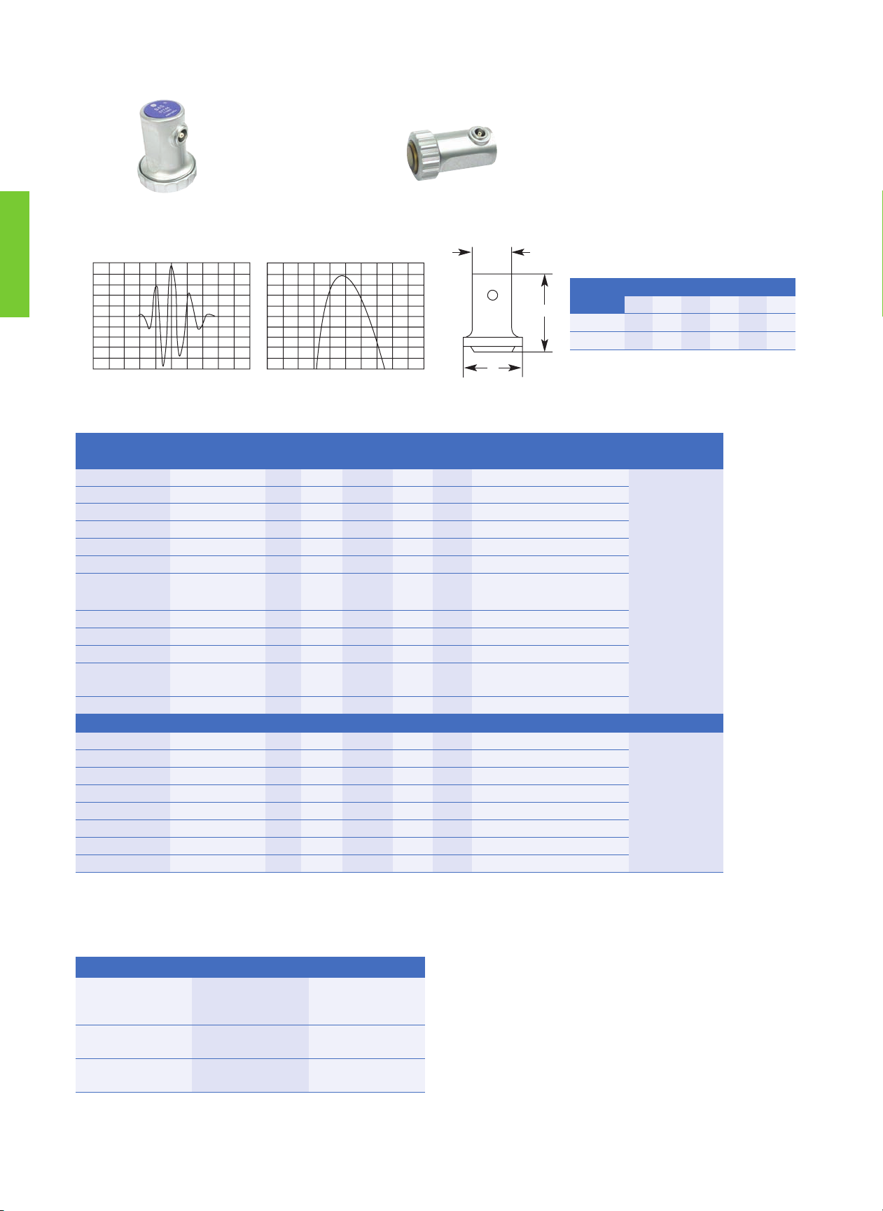
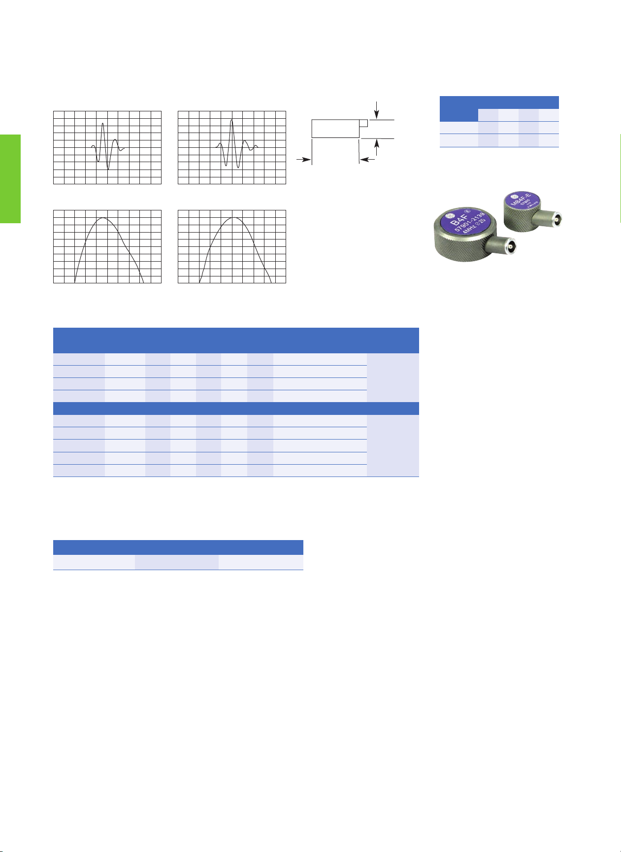
Protective Face Transducers—European Standards
Types B..S and MB..S
Typical waveform and frequency spectrum
50mV/Div
0,5μS/Div 0 - 4MHz
2dB/Div
B2S
pulse shape
spectrum
C
A
B
B..S
MB..S
Case
Type
A B C
mm in mm in mm in
Type 2 30 1.18 59 2.32 45 1.69
Type 3 20 0.79 43 1.77 25 0.98
Page 9
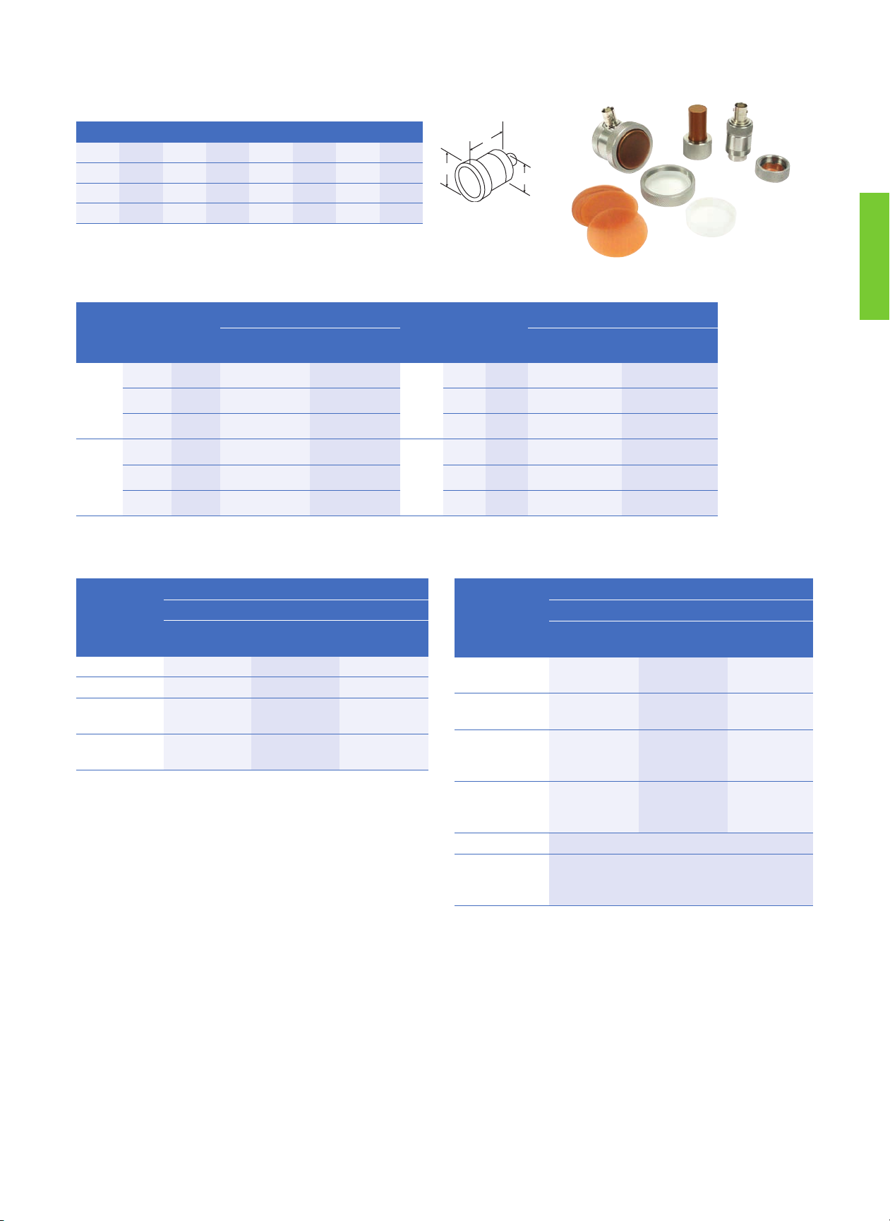
7
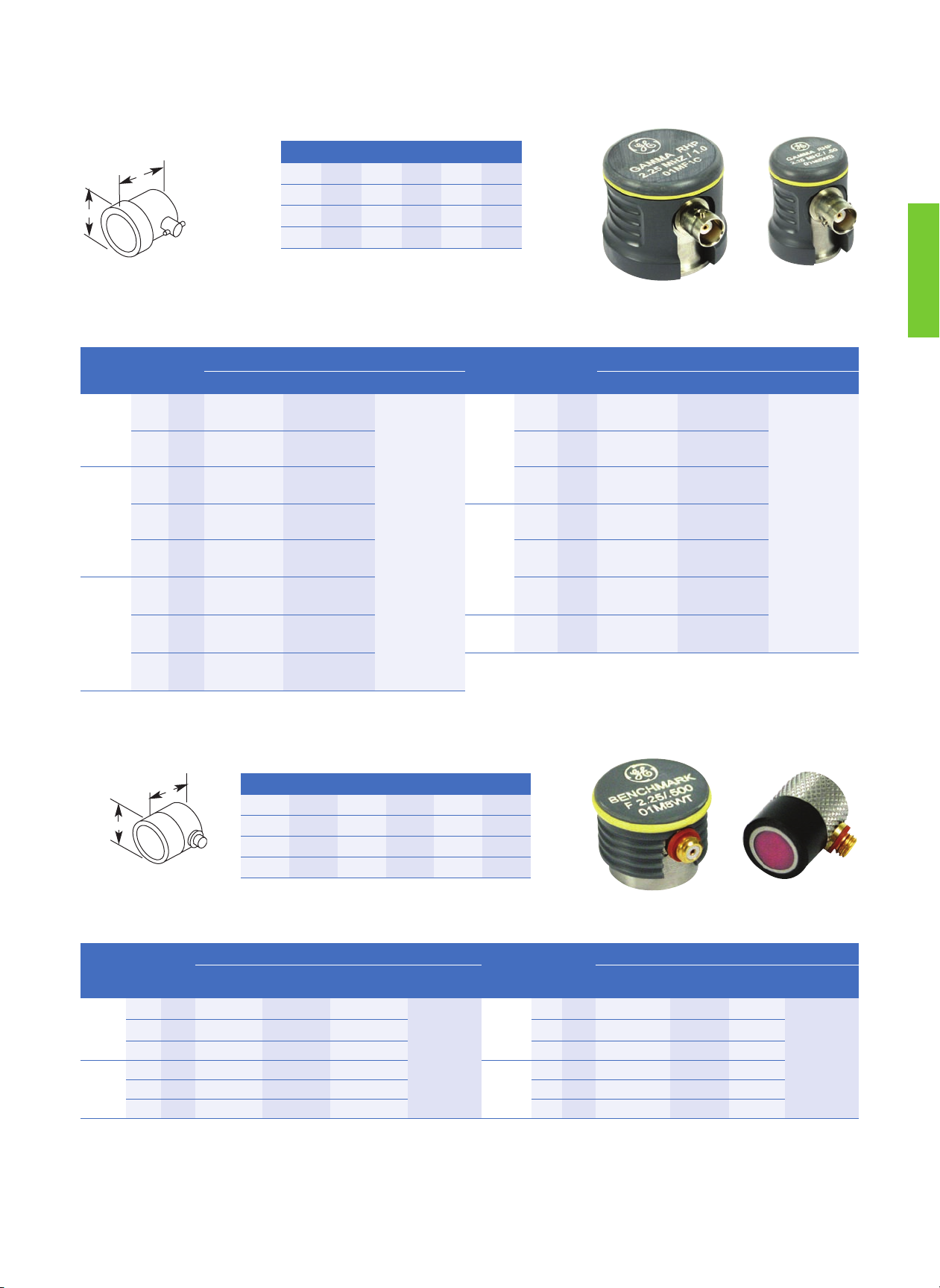
Protective Face Transducers—North American Standards
Protective Face Combination Transducers—Type PFCR (Side Mount BNC), PFCS (Top Mount BNC)
Note: Protective face option kits sold separately. Custom configurations are available by special order.
Protective Face Option Kits—PFCR/PFCS
Element Ø A B C
mm in mm in mm in mm in
13 0.50 19.1 0.75 30.5 1.20 23.9 0.94
19 0.75 25.4 1.00 30.5 1.20 30.2 1.19
25 1.00 31.8 1.25 30.5 1.20 36.6 1.44
Freq.
(MHz)
Element Ø
mm in
Order Code
Freq.
(MHz)
Element Ø
mm in
Order Code
Gamma Series
PFCR
Gamma Series
PFCS
Gamma Series
PFCR
Gamma Series
PFCS
1.0
13 0.50 241-240 241-260
3.50
13 0.50 243-240 243-260
19 0.75 251-240 251-260 19 0.75 253-240 253-260
25 1.00 261-240 261-260 25 1.00 263-240 263-260
2.25
13 0.50 242-240 242-260
5.0
13 0.50 244-240 244-260
19 0.75 252-240 252-260 19 0.75 254-240 254-260
25 1.00 262-240 262-260 25 1.00 264-240 264-260
Order Code
Transducer Element Ø
.5 in
(13 mm)
.75 in (19 mm) 1.00 in
(25 mm)
Spare Membranes
pkg. of 12 pcs.
118-220-020 118-220-021 118-220-022
Spare Wear Caps
pkg. of 12 pcs.
118-240-123 118-240-122 118-240-121
Hi-Temp. Delay
Line* 1.0 in
(25.4 mm) length
118-440-027 118-440-031 118-440-035
Hi-Temp. Delay
Line* 1.5 in
(38.1 mm) length
118-440-029 118-440-033 118-440-037
BNC Cable 118-140-016
Membrane, Wear
Cap and Delay
Line Couplant
118-300-740
Kit Styles
Order Code
Transducer Element Ø
.5 in
(13 mm)
.75 in
(19 mm)
1.00 in
(25 mm)
PM 118-450-120 118-450-140 118-450-160
PWC 118-450-220 118-450-240 118-450-260
PHTD - 1.0 in
(25.4 mm) Delay
118-450-320 118-450-340 118-450-360
PHTD - 1.5 in
(38.1 mm) Delay
118-450-420 118-450-440 118-450-460
* High Temp (PHTD) delay line: maximum temperature 400°F (200°C), maximum
contact time 10 seconds; cool to ambient before reuse.
B
A
C
Style PM Kit includes a knurled ring, gland nut, wrench,
12 membranes, and a 2 oz. bottle of couplant (transducer not
included).
Style PWC Kit includes a knurled ring, three wear caps, and a
2 oz. bottle of couplant (transducer not included). This option may
not be usable if near surface resolution is critical.
Style PHTD Kit includes a knurled ring, high temperature delay
line, and a 2 oz. bottle of couplant (transducer not included).
Page 10
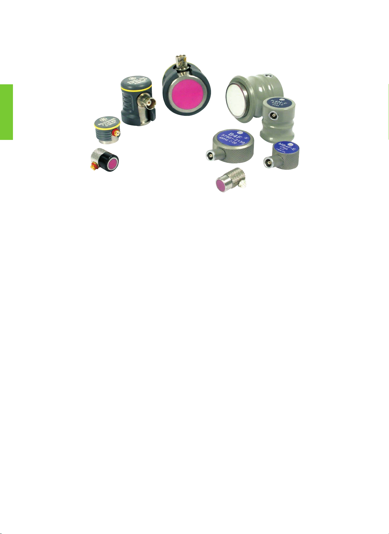
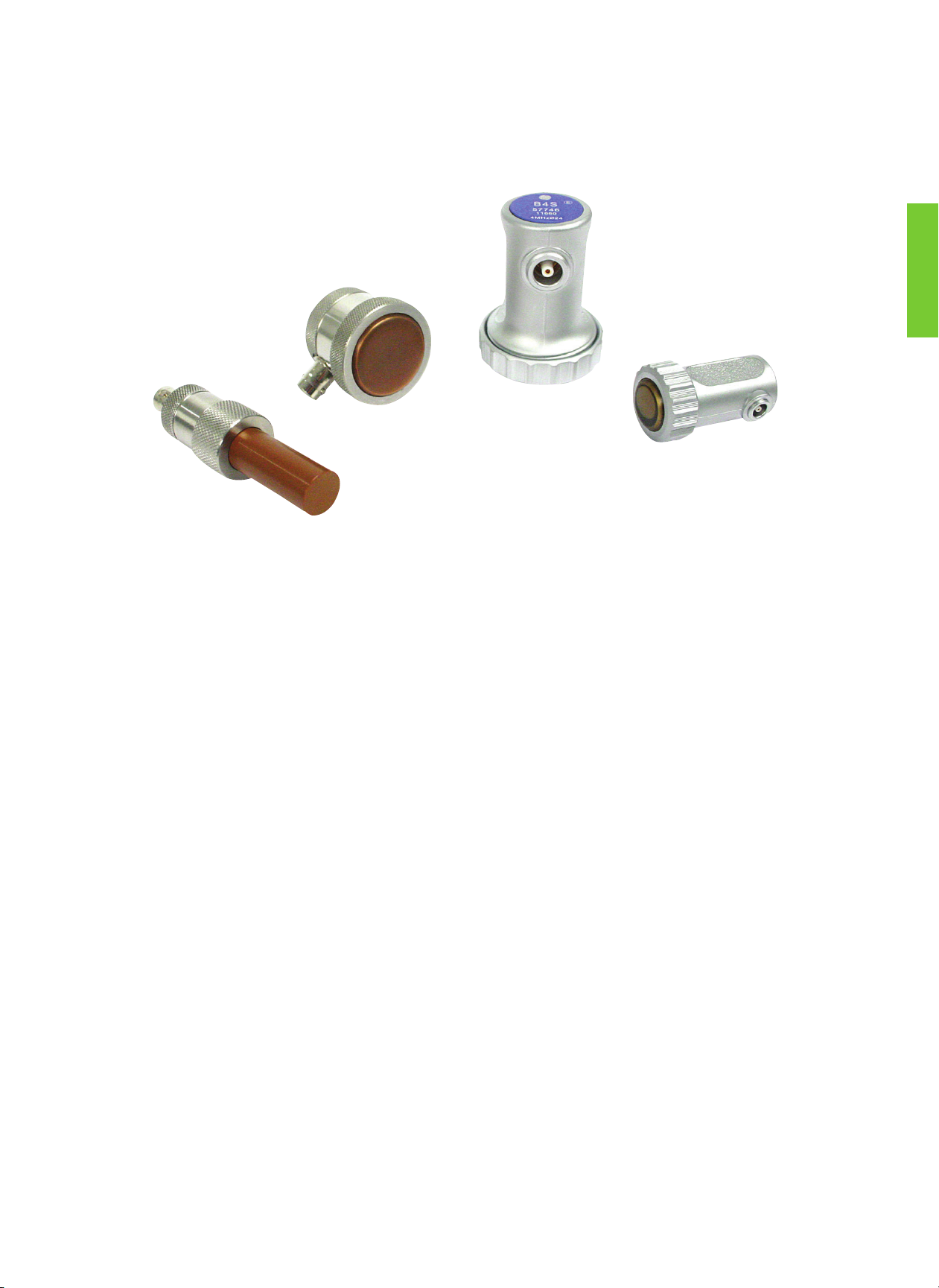
8
Applications
• General purpose, metal parts with simple geometry
• Manual inspection of plate, large forgings, billets, castings
• Smaller models for pipe and tube, tanks, bars, small forgings
• Lamination, delamination
• Bond testing
• Thick sections or difficult to penetrate materials
Features and Benefits
• Permanent, abrasion—resistant wear plate
• Best match to metals
• Higher gain reserve than protective face models
• Fingertip models for access to tight spaces
• Comfortable grip
• European models have side mounted Lemo 00 connectors, side mounted Microdot on K..K and G..K types.
• North American models have BNC connectors (side or top mount), side mounted Microdot on F type.
Straight Beam Contact Transducers, Wear Resistant
Page 11
9
Type
Order
CodeDmm inf(MHz)Nmm in
Notes Sketch
K 1 G 58506 24
0.94
1 23
0.9
Type 5
K 2 G 58507 24
0.94
2 45
1.8
K 2 G-EN 500071 24
0.94
2 45
1.8
DIN EN 12668-2 compliant
K 4 G 58508 24
0.94
4 88
3.5
K 4 G-EN 500072 24
0.94
4 88
3.5
DIN EN 12668-2 compliant
K 1 N 67620 10
0.39
1 4
0.2
Type 6
K 2 N 58509 10
0.39
2 8
0.3
K 4 N 58510 10
0.39
4 16
0.6
K 5 N 58511 10
0.39
5 20
0.8
K 5 K 52831 5
0.20
5 5
0.2
Type 7
K 5 K-EN 500061 5
0.20
5 5
0.2
DIN EN 12668-2 compliant
K 10 K 52832 5
0.20
10 10
0.4
K 10 K-EN 500062 5
0.20
10 10
0.4
DIN EN 12668-2 compliant
G 1 N 58500 24
0.94
1 23
0.9
Type 5G 2 N 58501 24
0.94
2 45
1.8
G 4 N 58502 24
0.94
4 88
3.5
G 2 KB 58503 10
0.39
2 8
0.3
Type 6
G 5 KB 58504 10
0.39
5 20
0.8
G 5 K 53057 5
0.20
5 5
0.2
Type 7
G 10 K 53052 5
0.20
10 10
0.4
Custom configurations are available by special order.
Description Type Remark
Probe Cable MPKL2
(50486)
MPKM2
(52999)
for K..G, K..N,
G..N, and
G..KB
for K..K and
G..K
Accessories
For explanations to the table data, refer to Selection Criteria on pages 2 through 4.
K..G, G..N K..N, G..KB
K..K, G..K
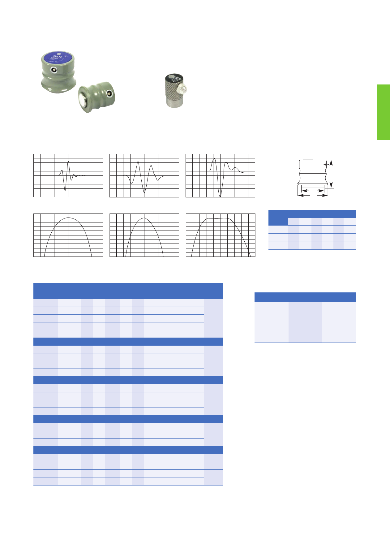
Wear Resistant Transducers—European Standards
Typical waveform and frequency spectrum
Types K..G, K..N, K..K, G..N, G..KB and G..K
3V/Div 0,2V/Div
0,1μS/Div0,5μS/Div
0 - 4MHz 0 - 10MHz
2dB/Div 2dB/Div
K2G-F K5K
A
C
B
0, 5V/Div
G2N-F
0, 25μS/Div
2dB/Div
0 - 4MHz
Case
Type
A B C
mm in mm in mm in
Type 5 30 1.18 37 1.46 40 1.57
Type 6 15 0.59 31 1.22 26 1.02
Type 7 10 0.39 17 0.67
Page 12
10
Wear Resistant Transducers—European Standards
For explanations to the table data, refer to Selection Criteria on pages 2 through 4.
Custom configurations are available by special order.
Description Type Remark
Cable MPKL2 (50486) for B..F and MB..F
Types B..F and MB..F
Typical waveform and frequency spectrum
B
A
1,0V/Div 2,0V/Div
0,2μS/Div
0,5μS/Div
0 - 4MHz 0 - 8MHz
2dB/Div 2dB/Div
B2F MB4F
Type
Order
CodeDmm inf(MHz)Nmm in
Notes Sketch
B 1 F 57899 20
0.79
1 16
0.6
Type 8
B 2 F 57900 20
0.79
2 31
1.2
B 4 F 57901 20
0.79
4 62
2.4
B 5 F 57902 20
0.79
5 76
3.0
MB 2 F 57904 10
0.39
2 8
0.3
Type 9
M B 4 F 57905 10
0.39
4 16
0.6
M B 4 F-EN 500073 10
0.39
4 16
0.6
DIN EN 12668-2 compliant
MB 5 F 57906 10
0.39
5 19
0.8
MB 10 F 57903 10
0.39
10 32
1.4
Case
Type
A B
mm in mm in
Type 8 31 1.22 16 0.63
Type 9 19 0.75 16 0.63
Accessories
Page 13
11
Fingertip Contact Transducers—Type F
Element Ø A B
mm in mm in mm in
6
0.25
12.7
0.50
16.8
0.66
10
0.375
16.0
0.63
16.8
0.66
13
0.50
19.1
0.75
16.8
0.66
Freq.
(MHz)
Element Ø
mm in
Order Code
Freq.
(MHz)
Element Ø
mm in
Order Code
Benchmark
Series
Alpha
Series
Gamma
Series
Accessories
Benchmark
Series
Alpha
Series
Gamma
Series
Accessories
2.25
6
.250
822-000 122-000 222-000
Cables
BNC
118-140-012
LEMO-1
118-140-022
5.0
6
.250
824-000 124-000 224-000
Cables
BNC
118-140-012
LEMO-1
118-140-022
10
.375
832-000 132-000 232-000 10
.375
834-000 134-000 234-000
13
.500
842-000 142-000 242-000 13
.500
844-000 144-000 244-000
3.5
6
.250
123-000 223-000
10.0
6
.250
126-000 226-000
10
.375
133-000 233-000 10
.375
136-000 236-000
13
.500
143-000 243-000 13
.500
146-000 246-000
A
B
Custom configurations are available by special order.
Type F
Standard Contact Transducers—Type RHP-CR (Side Mount BNC), RHP-CS (Top Mount BNC)
Freq.
(MHz)
Element Ø
mm in
Order Code
Freq.
(MHz)
Element Ø
mm in
Order Code
Alpha Series Gamma Series Accessories Alpha Series Gamma Series Accessories
.5
19 0.75
250-043-CR
250-123-CS
Cables
BNC
118-140-016
LEMO-1
118-140-018
3.5
13 0.50
243-043-CR
243-123-CS
Cables
BNC
118-140-016
LEMO-1
118-140-018
25 1.00
260-043-CR
260-123-CS
19 0.75
253-043-CR
253-123-CS
1.0
13 0.50
241-043-CR
241-123-CS
25 1.00
263-043-CR
263-123-CS
19 0.75
251-043-CR
251-123-CS
5.0
13 0.50
144-043-CR
144-123-CS
244-043-CR
244-123-CS
25 1.00
261-043-CR
261-123-CS
19 0.75
154-043-CR
154-123-CS
254-043-CR
254-123-CS
2.25
13 0.50
142-043-CR
142-123-CS
242-043-CR
242-123-CS
25 1.00
164-043-CR
164-123-CS
264-043-CR
264-123-CS
19 0.75
152-043-CR
152-123-CS
252-043-CR
252-123-CS
10.0 13 0.50
246-043-CR
246-123-CS
25 1.00
162-043-CR
162-123-CS
262-043-CR
262-123-CS
Custom configurations are available by special order.
Wear Resistant Transducers—North American Standards
A
B
Element Ø A B
mm in mm in mm in
13 0.50 29.2 1.15 38.1 1.50
25 0.75 35.6 1.40 38.1 1.50
19 1.00 41.9 1.65 38.1 1.50
Type RHP
Page 14
12
Straight Beam Contact Transducers, Delay Line
Applications
• Thickness measurement
• Near surface flaw detection
• Inspection of thin sections
• Curved parts, tubing, pipe
• Composites and plastics
• Turbine blades
Features and Benefits
• Excellent near surface resolution.
• Replaceable delay line—long life and versatility.
• Higher frequencies improve resolution and small flaw detectability.
• All models have side mounted Microdot connector.
Page 15
13
Description Type Remark
Cable
Delay Line
(exchangeable)
MPKM2 (52999)
CLFV1 (54258)
CLFV3 (54262)
.37 in (9.5 mm) for G.MN
.49 in (12.5 mm) for G.MN
0, 25μS/Div
2dB/Div
0 - 20MHz
21
ø 7.6
13
Delay Line Transducers—European Standards
Typical waveform and frequency spectrum
2, 5V/Div
G10MN
Type
Order
CodeDmm inf(MHz)
N
mm in
Sketch
G 5 MN 53046 5 0.20 5 5 0.2
Type 14G 10 MN 53047 5 0.20 10 10 0.4
G 15 MN 53058 5 0.20 15 15 0.6
Custom configurations are available by special order.
Type G..MN
Accessories
Page 16

14
Delay Line Transducers—North American Standards
Removable Delay Line—Type DFR
*H-007 fits .125 in (3 mm) and .25 in (6 mm) units only with exception of Mini DFR.
Custom configurations are available by special order.
Element Ø A B C
mm in mm in mm in mm in
3 or 6 0.125 or 0.25 13 0.51 21.3 0.84 7.6 0.30
13 0.50 22.4 0.88 35.1 1.38 15.2 0.60
Mini-DFR
3 0.125 10.41 0.41 19.6 0.77 4.8 0.19
Freq.
(MHz)
Element
Ø
mm in
Order Codes
Alpha
Series
Delay Line
10-PK .38 in
(9.5 mm) Lg
Delay Line
10-PK .5 in
(12.7 mm) Lg
Accessories
2.25
6 .250 122-660 118-440-050 118-440-051
Cables
BNC
118-140-012
LEMO-1
118-140-022
Delay Line
Couplant
118-300-740
Spring Loaded
VEE Block
118-480-007
13 .500 140-500 118-440-052
3.5 6 .250 123-660 118-440-050 118-440-051
5.0
6 .250 124-660 118-440-050 118-440-051
13 .500 144-660 118-440-052
10.0
6 .250 126-660 118-440-050 118-440-051
13 .500 140-602 118-440-052
15.0 6 .250 127-660 118-440-050 118-440-051
22.0 3 .125 118-660 118-440-050 118-440-051
Mini-
DFR
20.0
3 .125 518-650 118-440-502
C
B
A
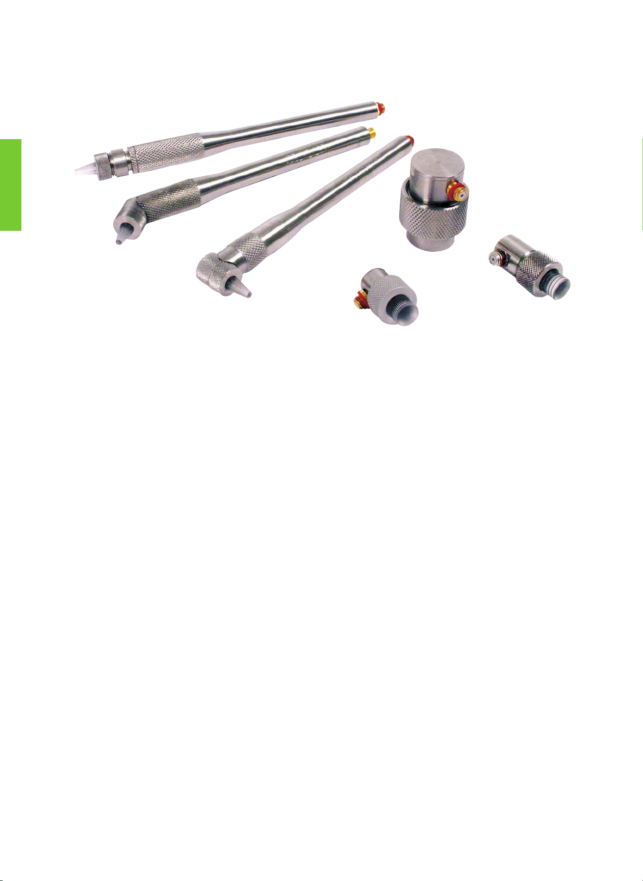
K-PEN Replaceable Delay Line Pencil Probe
• Focused, high resolution pencil probe
• Interchangeable delay lines, two tip diameters
• Extremely small contact area
• Tightly curved surfaces, such as turbine blades
• Wall thickness measurement from the bottom of an external pit
• Straight, right angle and 45° handles
• Straight model has removable handle
Freq.
(MHz)
Order Code
Straight K-PEN 45° K-PEN
Right Angle
K-PEN
.065 in (1.7 mm)
Tip Delay 10-PK
.090 in (2.3 mm)
Tip Delay 10-PK
BNC Cable
7.5 389-042-200 389-042-880 389-042-870
387-003-109 387-003-110 118-140-012
20.0 389-030-290 389-041-270 389-040-660
Types DFR and K-PEN
4.93
0.30
0.42
1.10
0.30
0.78
0.42
4.25
0.30
0.78
3.75
Page 17

15
Applications
• Remaining wall thickness, corrosion, erosion
• Near surface flaw detection
• Small parts—screws, bolts, pins
• Cladding and weld overlay
• Bond testing
• Railroad wheels
• Core flaws in shafts, bars, billets
• Coarse grain materials
Features and Benefits
• Excellent near surface resolution
• Improved coupling on curved and rough surfaces
• Reduce noise caused by scattering
• Can be contoured for curved parts
• European models have side mounted Lemo 00 connectors, side mounted Microdot SEB..KF types
• North American models have fixed BNC cable (ADP) or side mounted MMD (FDU)
Straight-Beam Contact Transducers, Dual Element (TR)
Page 18

16
Type
Order
Code
a x b
mm inf(MHz)Fmm in
Notes Sketch
SEB 1 57466 21 /2 ø 0.83 1 20 0.8
Type 15
SEB 1-EN 500176 21 /2 ø 0.83 1 20 0.8 DIN EN 12668-2 compliant
SEB 2 57467 7 x 18 .28 x .71 2 15 0.6
SEB 2-EN 500063 7 x 18 .28 x .71 2 15 0.6 DIN EN 12668-2 compliant
SEB 2-0° 57468 7 x 18 .28 x .71 2 30 1.2 Elements at 0° included angle
SEB 2-EN-0° 500065 7 x 18 .28 x .71 2 30 1.2
Elements at 0° included angle
DIN EN 12668-2 compliant
SEB 4 57469 6 x 20 .24 x .79 4 12 0.5
SEB 4-EN 500064 6 x 20 .24 x .79 4 12 0.5 DIN EN 12668-2 compliant
SEB 4-0° 57470 6 x 20 .24 x .79 4 25 1.0 Elements at 0° included angle
SEB 4-EN-0° 500066 6 x 20 .24 x .79 4 25 1.0
Elements at 0° included angle
DIN EN 12668-2 compliant
MSEB 2 57461 11 /2 ø 0.43 2 8 0.3
Type 16
MSEB 2-EN 500067 11 /2 ø 0.43 2 8 0.3 DIN EN 12668-2 compliant
MSEB 4 57462 3.5 x 10 .14 x .39 4 10 0.4
MSEB 4-EN 500068 3.5 x 10 .14 x .39 4 10 0.4 DIN EN 12668-2 compliant
MSEB 4-0° 57463 3.5 x 10 .14 x .39 4 18 0.7 Elements at 0° included angle
MSEB 5 57464 9 /2 ø 0.35 5 10 0.4 Typical bandwidth 100%
SEB 2 KF5 56464 8 /2 ø 0.31 2 6 0.24
Type 17
SEB 4 KF8 56465 8 /2 ø 0.31 4 6 0.24
SEB 4 KF8-EN 500069 8 /2 ø 0.31 4 6 0.24 DIN EN 12668-2 compliant
SEB 5 KF3 56466 8 /2 ø 0.31 5 3 0.12
SEB10 KF3 56867 5 /2 ø 0.20 10 3 0.12
Type 18
SEB10 KF3-EN 500070 5 /2 ø 0.20 10 3 0.12 DIN EN 12668-2 compliant
Custom configurations are available by special order.
Description Type Remark
Cable SEKG2 (53887)
SEKM2 (53001)
for SEB.., MSEB..,
for SEB..KF
Accessories
For explanations to the table data, refer to Selection Criteria on pages 2 through 4.
SEB MSEB SEB...KF
Dual Element (TR) Contact Transducers—European Standards
2dB/Div2dB/Div
10mV/Div0, 2V/Div
MSEB4
SEB4KFB
0, 2μs/Div
0-8MHz
0, 2μs/Div
0-8MHz
Typical waveform and frequency spectrum
Case
Type
A B C D
mm in mm in mm in mm in
Type 15 30 1.18 65 2.56 28.5 1.12 10 0.39
Type 16 20 0.79 45 1.77 16.5 0.65 5 0.20
Type 17 14 0.55 17 0.67 13 0.51 6.4 0.25
Type 18 14 0.55 17 0.67 7.5 0.30 6.4 0.25
Types SEB and MSEB
A
C
B
Types 15 and 16 Types 17 and 18
D
C
B
D
A
Page 19

17
Dual Element (TR) Contact Transducers—North American Standards
Dual Element Transducers—Types ADP and FDU
FDUADP
Element Ø A B
mm in mm in mm in
6 .25 9.7 0.38 12.7 0.50
10 .375 12.7 0.50 12.7 0.50
Element Ø A B C
mm in mm in mm in mm in
6 0.25 12.7 .50 16.3 .64 9.1 .36
10 0.375 16.0 .63 16.3 .64 11.9 .47
13 0.50 19.1 .75 17.3 .68 15.2 .60
Freq.
(MHz)
Element Ø Order Code
Freq.
(MHz)
Element Ø Order Code
mm in ADP Dual
FDU Dual
†
mm in ADP Dual
FDU Dual
†
2.25
6 .250 222-700 222-680
5.0
6 .250 224-700 224-680
10 .375 232-700 232-680 10 .375 234-700 234-680
13 .500 242-700 13 .500 244-700
3.5
6 .250 223-700 223-680 7.5 8 .300 135-700
10 .375 233-700 233-680
10.0
6 .250 389-002-771
13 .500 243-700 13 .500 389-021-830
† Standard MMD to BNC dual cable (118-140-014) sold separately. Custom configurations are available by special order.
B
A
B
A
C
Types ADP and FDU
ADP
FDU
Page 20

18
Applications
• General weld inspection, larger objects, thicker sections
• Pipes, tanks, pressure vessels
• Axles, forgings, castings
• Bridges and other structures
• Railroad wheels and rail
Features and Benefits
• European models have integral wedge
– Maximum precision and repeatability for DGS flaw sizing method
– Durable, ergonomically designed die cast housing
– Replacement soles (sold separately) for extended service life
– Lemo 1 connector on WB and WK types, side mount standard, top mount optional
– Lemo 00 connector on SWB and SWK types, side mount
• North American models have interchangeable wedges (sold separately)
– Maximum versatility and service life
– Custom wedge angles and curvatures can be special ordered
– AWS models available for AWS Structural Welding Code D1.1
– High temperature wedges available for testing to 200°C (400°F)
– BNC connector, top mount
Angle Beam Transducers—Large Sizes
Page 21

19
Type
Order
Code
a x b
mm in
f
(MHz)ß(Steel)Nmm in
Notes Sketch
WB 45-1
WB 45-1-EN
WB 45-O1
56993
500207
57217
20 x 22
20 x 22
20 x 22
.79 x .87
.79 x .87
.79 x .87
1
1
1
45
45
45
45
45
45
1.8
1.8
1.8
DIN EN 12668-2 compliant
Top connector
Type 21
WB 60-1
WB 60-1-EN
WB 60-O1
56994
500208
57218
20 x 22
20 x 22
20 x 22
.79 x .87
.79 x .87
.79 x .87
1
1
1
60
60
60
45
45
45
1.8
1.8
1.8
DIN EN 12668-2 compliant
Top connector
WB 70-1
WB 70-1-EN
WB 70-O1
56995
500209
57219
20 x 22
20 x 22
20 x 22
.79 x .87
.79 x .87
.79 x .87
1
1
1
70
70
70
45
45
45
1.8
1.8
1.8
DIN EN 12668-2 compliant
Top connector
WB 35-2
WB 35-2-EN
WB 35-O2
WB 35-O2EN
56998
500054
57222
500058
20 x 22
20 x 22
20 x 22
20 x 22
.79 x .87
.79 x .87
.79 x .87
.79 x .87
2
2
2
2
38
38
38
38
90
90
90
90
3.5
3.5
3.5
3.5
DIN EN 12668-2 compliant
Top connector
DIN EN 12668-2 compliant
WB 45-2
WB 45-2-EN
WB 45-O2
WB 45-O2EN
56999
500055
57223
500059
20 x 22
20 x 22
20 x 22
20 x 22
.79 x .87
.79 x .87
.79 x .87
.79 x .87
2
2
2
2
45
45
45
45
90
90
90
90
3.5
3.5
3.5
3.5
DIN EN 12668-2 compliant
Top connector
DIN EN 12668-2 compliant
WB 60-2
WB 60-2-EN
WB 60-O2
WB 60-O2EN
57000
500056
57224
500060
20 x 22
20 x 22
20 x 22
20 x 22
.79 x .87
.79 x .87
.79 x .87
.79 x .87
2
2
2
2
60
60
60
60
90
90
90
90
3.5
3.5
3.5
3.5
DIN EN 12668-2 compliant
Top connector
DIN EN 12668-2 compliant
WB 70-2
WB 70-2-EN
WB 70-O2
WB 70-O2EN
57001
500057
57225
500280
20 x 22
20 x 22
20 x 22
20 x 22
.79 x .87
.79 x .87
.79 x .87
.79 x .87
2
2
2
2
70
70
70
70
90
90
90
90
3.5
3.5
3.5
3.5
DIN EN 12668-2 compliant
Top connector
DIN EN 12668-2 compliant
WB 80-2
WB 80-2-EN
WB 80-O2
57002
500278
57226
20 x 22
20 x 22
20 x 22
.79 x .87
.79 x .87
.79 x .87
2
2
2
77
77
77
90
90
90
3.5
3.5
3.5
DIN EN 12668-2 compliant
Top connector
WB 90-2
WB 90-2-EN
WB 90-O2
57003
500266
57227
20 x 22
20 x 22
20 x 22
.79 x .87
.79 x .87
.79 x .87
2
2
2
90
90
90
90
90
90
3.5
3.5
3.5
DIN EN 12668-2 compliant
Top connector
Large Angle Beam Transducers—European Standards
WB45-2 WK60-2
0.1V/Div
1.0μs/Div
5dB/Div
0-4 MHz
0.1V/Div
1.0μs/Div
5dB/Div
0-4 MHz
C
D
B
A
Typical waveform and frequency spectrum
Types WB/WK and SWB/SWK
WB-O
Case
Type
A B C D
mm in mm in mm in mm in
Type 20 21.5 0.85 37 1.46 31 1.22 3 0.12
Type 21 29 1.14 53.5 2.11 45 1.77 5 0.20
Types WB/WK and SWB/SWK
WB, WK
SWB, SWK
Page 22

20
Large Angle Beam Transducers—European Standards
Description Type Remark
Cable PKLL2 (50326)
MPKL2 (50486)
for WB.., WK..
for SWB.., SWK..
Spare sole
(1 set = 10 pcs)
WP(E) (57276)
SWP (58514)
for WB.., WK..
for SWB.., SWK
Type
Order
Code
a x b
mm in
f
(MHz)ß(Steel)Nmm in
Notes Sketch
WB 35-4
WB 35-O4
57004
57228
20 x 22
20 x 22
.79 x .87
.79 x .87 44
38
38
180
180
7.1
7.1 Top connector
Type 21
WB 45-4
WB 45-4-EN
WB 45-O4
57005
500200
57229
20 x 22
20 x 22
20 x 22
.79 x .87
.79 x .87
.79 x .87
4
4
4
45
45
45
180
180
180
7.1
7.1
7.1
DIN EN 12668-2 compliant
Top connector
WB 60-4
WB 60-4-EN
WB 60-O4
57006
500201
57230
20 x 22
20 x 22
20 x 22
.79 x .87
.79 x .87
.79 x .87
4
4
4
60
60
60
180
180
180
7.1
7.1
7.1
DIN EN 12668-2 compliant
Top connector
WB 70-4
WB 70-4-EN
WB 70-O4
57007
500202
57231
20 x 22
20 x 22
20 x 22
.79 x .87
.79 x .87
.79 x .87
4
4
4
70
70
70
180
180
180
7.1
7.1
7.1
DIN EN 12668-2 compliant
Top connector
WB 80-4
WB 80-O4
57008
57232
20 x 22
20 x 22
.79 x .87
.79 x .87
4
4
77
77
180
180
7.1
7.1 Top connector
SWB 45-2
SWB 60-2
SWB 70-2
58414
58415
58416
14 x 14
14 x 14
14 x 14
.55 x .55
.55 x .55
.55 x .55
2
2
2
45
60
70
39
39
39
1.5
1.5
1.5
Type 20
SWB 45-5
SWB 60-5
SWB 70-5
58420
58421
58422
14 x 14
14 x 14
14 x 14
.55 x .55
.55 x .55
.55 x .55
5
5
5
45
60
70
98
98
98
3.9
3.9
3.9
WK 45-1
WK 60-1
WK 70-1
67889
67890
67891
20 x 22
20 x 22
20 x 22
.79 x .87
.79 x .87
.79 x .87
1
1
1
45
60
70
45
45
45
1.8
1.8
1.8
Piezocomposite
element
Type 21
WK 45-2
WK 60-2
WK 70-2
57011
57012
57013
20 x 22
20 x 22
20 x 22
.79 x .87
.79 x .87
.79 x .87
2
2
2
45
60
70
90
90
90
3.5
3.5
3.5
SWK 45-2
SWK 60-2
SWK 70-2
58843
58844
58845
14 x 14
14 x 14
14 x 14
.55 x .55
.55 x .55
.55 x .55
2
2
2
45
60
70
39
39
39
1.5
1.5
1.5
Piezocomposite
element
Type 20
Custom configurations are available by special order.
Accessories
For explanations to the table data, refer to Selection Criteria on pages 2 through 4.
Page 23

21
Large Angle Beam Transducers—North American Standards
Angle Beam Transducers—Types SWS and AWS
Element Size A B C D
mm in mm in mm in mm in mm in
13 Ø .50 Ø 18.3 .72 25.4 1.00 19.1 .75 20.6 .81
13 x 25 .50 x 1.0 18.5 .725 38.4 1.51 19.1 .75 33.3 1.31
19 x 25 .75 x 1.0 25.4 1.00 38.1 1.5 19.1 .75 33.3 1.31
25 Ø 1.0 31.0 1.22 41.9 1.65 19.1 .75 35.1 1.38
16 x 16 .63 x .63 18.5 .73 31.8 1.25 19.1 .75 25.4 1.00
16 x 19 .63 x .75 18.5 .73 31.8 1.25 19.1 .75 25.4 1.00
19 x 19 .75 x .75 21.6 .85 31.8 1.25 19.1 .75 25.4 1.00
Freq.
(MHz)
Element Ø
mm in
Order Codes
Freq.
(MHz)
Element Ø
mm in
Order Codes
Gamma
Series
Benchmark
Series
Standard
Wedge
(W = 118-340)
Hi-Temp
Wedge*
(W = 118-340)
Accessories
Gamma
Series
Benchmark
Series
Standard
Wedge
(W = 118-340)
Hi-Temp
Wedge*
(W = 118-340)
Accessories
0.50 25 1.0 260-600
W-021 45°
W-022 60°
W-023 70°
W-025 90°
W-081 45°
W-082 60°
W-083 70°
Cables
BNC
118-140-016
LEMO-1
118-140-018
Wedge
Couplant
118-300-740
2.25
AWS
Series
16 x16.63 x
.63
292-603 892-603
W-104 45°
W-105 60°
W-106 70°
Cables
BNC
118-140-016
LEMO-1
118-140-018
Wedge
Couplant
118-300-740
16 x19.63 x
.75
292-601 892-601
W-104 45°
W-105 60°
W-106 70°
1.0
13 0.5 241-600 841-600
W-009 45°
W-010 60°
W-011 70°
W-013 90°
W-076 45°
W-077 60°
W-078 70°
19 x19.75 x
.75
292-604 892-604
W-104 45°
W-105 60°
W-106 70°
13 x 250.5 x
1
291-600 891-600
W-015 45°
W-016 60°
W-017 70°
W-019 90°
W-070 45°
W-086 60°
W-071 70°
3.5
13 0.5 243-600 843-600
W-009 45°
W-010 60°
W-011 70°
W-013 90°
W-076 45°
W-077 60°
W-078 70°
19 x25.75 x
1
291-605 891-605
W-051 45°
W-052 60°
W-053 70°
W-054 90°
13 x250.5 x
1
293-600 893-600
W-015 45°
W-016 60°
W-017 70°
W-019 90°
W-070 45°
W-086 60°
W-071 70°
25 1.0 261-600 861-600
W-021 45°
W-022 60°
W-023 70°
W-025 90°
W-081 45°
W-082 60°
W-083 70°
19 x25.75 x
1
293-605 893-605
W-051 45°
W-052 60°
W-053 70°
W-054 90°
2.25
13 0.5 242-600 842-600
W-009 45°
W-010 60°
W-011 70°
W-013 90°
W-076 45°
W-077 60°
W-078 70°
25 1.0 263-600 863-600
W-021 45°
W-022 60°
W-023 70°
W-025 90°
W-081 45°
W-082 60°
W-083 70°
13 x250.5 x
1
292-600 892-600
W-015 45°
W-016 60°
W-017 70°
W-019 90°
W-070 45°
W-086 60°
W-071 70°
5.0
13 .5 244-600 844-600
W-009 45°
W-010 60°
W-011 70°
W-013 90°
W-076 45°
W-077 60°
W-078 70°
19 x25.75 x
1
292-605 892-605
W-051 45°
W-052 60°
W-053 70°
W-054 90°
13 x25.5 x
1
294-600 894-600
W-015 45°
W-016 60°
W-017 70°
W-019 90°
W-070 45°
W-086 60°
W-071 70°
25 1.0 262-600 862-600
W-021 45°
W-022 60°
W-023 70°
W-025 90°
W-081 45°
W-082 60°
W-083 70°
19 x25.75 x
1
294-605 894-605
W-051 45°
W-052 60°
W-053 70°
W-054 90°
25 1.0 264-600 864-600
W-021 45°
W-022 60°
W-023 70°
W-025 90°
W-081 45°
W-082 60°
W-083 70°
D
C
B
A
* Duty Cycle: at 400°F (200°C), maximum contact time is 10 seconds; cool to ambient before reuse. Note: Standard wedge angles are specified for carbon steel. Custom
configurations are available by special order.
Types SWS and AWS
Page 24

22
Applications
• General weld inspection, smaller objects, thinner sections
• Tubes, pipes, pressure vessels, containers
• Pumps, valve housings
• Turbine blades, shafts
• Wheel rims
Features and Benefits
• European models have integral wedge
– Maximum precision and repeatability for DGS flaw sizing method
– Durable, ergonomically-designed die cast housing
– Replacement soles (sold separately) for extended service life
– Lemo 00 connector on MWB and MWK types, side mount standard, top mount optional
• North American models have interchangeable wedges (sold separately)
– Maximum versatility and service life
– Custom wedge angles and curvatures can be special ordered
– Both quick change and screw mounted styles available
– Microdot connector on MSW-QC and MSWS types, MMD on SMSWS
Angle Beam Transducers—Small Sizes
Page 25

23
Small Angle Beam Transducers—European Standards
Typical wavefarm and frequency spectrum
0, 2μs/Div
0, 2V/Div 0.5V/Div
5dB/Div2dB/Div
0-8 MHz
MWB45-4 MWK45-4
24
14
22
2
Type
Order
Code
a x b
mm inf(MHz)ß(Steel)Nmm in
Notes Sketch
MWB 35-2
MWB 35-2EN
MWB 35-O2
MWB 35-O2EN
56920
500040
57204
500044
8 x 9
8 x 9
8 x 9
8 x 9
.31 x .35
.31 x .35
.31 x .35
.31 x .35
2
2
2
2
38
38
38
38
15
15
15
15
0.6
0.6
0.6
0.6
DIN EN 12668-2 compliant
Top connector
DIN EN 12668-2 compliant
Type 23
MWB 45-2
MWB 45-2EN
MWB 45-O2
MWB 45-O2EN
56921
500041
57205
500045
8 x 9
8 x 9
8 x 9
8 x 9
.31 x .35
.31 x .35
.31 x .35
.31 x .35
2
2
2
2
45
45
45
45
15
15
15
15
0.6
0.6
0.6
0.6
DIN EN 12668-2 compliant
Top connector
DIN EN 12668-2 compliant
MWB 60-2
MWB 60-2EN
MWB 60-O2
MWB 60-O2EN
56922
500042
57206
500046
8 x 9
8 x 9
8 x 9
8 x 9
.31 x .35
.31 x .35
.31 x .35
.31 x .35
2
2
2
2
60
60
60
60
15
15
15
15
0.6
0.6
0.6
0.6
DIN EN 12668-2 compliant
Top connector
DIN EN 12668-2 compliant
MWB 70-2
MWB 70-2EN
MWB 70-O2
MWB 70-O2EN
56923
500043
57207
500234
8 x 9
8 x 9
8 x 9
8 x 9
.31 x .35
.31 x .35
.31 x .35
.31 x .35
2
2
2
2
70
70
70
70
15
15
15
15
0.6
0.6
0.6
0.6
DIN EN 12668-2 compliant
Top connector
DIN EN 12668-2 compliant
MWB 80-2
MWB 80-O2
MWB 90-2
56924
57208
56925
8 x 9
8 x 9
8 x 9
.31 x .35
.31 x .35
.31 x .35
2
2
2
77
77
90
15
15
15
0.6
0.6
0.6
Top connector
Surface wave
MWB-O MWB, MWK
Type MWB/MWK
Type 23
0, 2μs/Div
0-8 MHz
Page 26

24
Description Type Remark
Cable MPKL2 (50486) for MWB.., MWK..
Spare sole (1 set = 10 pcs) MWP(E) (57277) for MWB.., MWK..
Type
Order
Code
a x b
mm in
f
(MHz)ß(Steel)Nmm in
Notes Sketch
MWB 35-4
MWB 35-4EN
MWB 35-O4
MWB 35-O4EN
56926
500047
57210
500235
8 x 9
8 x 9
8 x 9
8 x 9
.31 x .35
.31 x .35
.31 x .35
.31 x .35
4
4
4
4
38
38
38
38
30
30
30
30
1.2
1.2
1.2
1.2
DIN EN 12668-2 compliant
Top connector
DIN EN 12668-2 compliant
Type 23
MWB 45-4
MWB 45-4EN
MWB 45-O4
MWB 45-O4EN
56927
500048
57211
500236
8 x 9
8 x 9
8 x 9
8 x 9
.31 x .35
.31 x .35
.31 x .35
.31 x .35
4
4
4
4
45
45
45
45
30
30
30
30
1.2
1.2
1.2
1.2
DIN EN 12668-2 compliant
Top connector
DIN EN 12668-2 compliant
MWB 60-4
MWB 60-4EN
MWB 60-O4
MWB 60-O4EN
56928
500049
57212
500237
8 x 9
8 x 9
8 x 9
8 x 9
.31 x .35
.31 x .35
.31 x .35
.31 x .35
4
4
4
4
60
60
60
60
30
30
30
30
1.2
1.2
1.2
1.2
DIN EN 12668-2 compliant
Top connector
DIN EN 12668-2 compliant
MWB 70-4
MWB 70-4EN
MWB 70-O4
MWB 70-O4EN
56929
500050
57213
500238
8 x 9
8 x 9
8 x 9
8 x 9
.31 x .35
.31 x .35
.31 x .35
.31 x .35
4
4
4
4
70
70
70
70
30
30
30
30
1.2
1.2
1.2
1.2
DIN EN 12668-2 compliant
Top connector
DIN EN 12668-2 compliant
MWB 80-4
MWB 80-O4
MWB 90-4
56930
57214
56931
8 x 9
8 x 9
8 x 9
.31 x .35
.31 x .35
.31 x .35
4
4
4
7
77
90
30
30
30
1.2
1.2
1.2
Top connector
Surface wave
MWK 45-2
MWK 60-2
MWK 70-2
67488
67489
67490
8 x 9
8 x 9
8 x 9
.31 x .35
.31 x .35
.31 x .35
2
2
2
45
60
70
15
15
15
0.6
0.6
0.6
Piezocomposite
element
Type 23
MWK 45-4
MWK 60-4
MWK 70-4
58938
58939
58940
8 x 9
8 x 9
8 x 9
.31 x .35
.31 x .35
.31 x .35
4
4
4
45
60
70
30
30
30
1.2
1.2
1.2
Custom configurations are available by special order.
Accessories
For explanations to the table data, refer to Selection Criteria on pages 2 through 4.
Small Angle Beam Transducers—European Standards
Page 27

25
Small Angle Beam Transducers—North American Standards
Miniature Angle Beam Transducers–Type MSW-QC (Quick Change)
Replaceable Wedge 10 mm (.375 in)
Wedge
Angle
A B C D E Thread
mm in mm in mm in mm in mm in in
45° 14.0 .55 22.6 .89 11.9 .47 14.7 0.58 14.0 0.55 1/2 - 28
60° 14.0 .55 26.4 1.04 14.0 .55 14.7 0.58 14.0 0.55 1/2 - 28
70° 14.0 .55 30.2 1.19 14.7 .58 14.7 0.58 14.0 0.55 1/2 - 28
90° 14.0 .55 29.2 1.15 15.5 .61 14.7 0.58 14.0 0.55 1/2 - 28
Replaceable Wedge 6 mm (.25 in)
Wedge
Angle
A B C D E Thread
mm in mm in mm in mm in mm in in
45° 11.4 .45 19.1 .75 9.4 .37 14.1 0.56 10.7 0.42 3/8 - 32
60° 11.4 .45 21.3 .84 11.2 .44 14.1 0.56 10.7 0.42 3/8 - 32
70° 11.4 .45 25.4 1.00 12.7 .50 14.1 0.56 10.7 0.42 3/8 - 32
90° 11.4 .45 24.1 .95 12.7 .50 14.1 0.56 10.7 0.42 3/8 - 32
Note: Standard wedge angles are specified for carbon steel. Custom configurations are available by special order.
Replaceable Wedge 13 mm (.50 in)
Wedge
Angle
A B C D E Thread
mm in mm in mm in mm in mm in in
45° 17.8 .70 26.7 1.05 14.0 .55 16.5 0.65 17.8 0.70 5/8 - 24
60° 17.8 .70 31.5 1.24 16.3 .64 16.5 0.65 17.8 0.70 5/8 - 24
70° 17.8 .70 35.8 1.41 17.3 .68 16.5 0.65 17.8 0.70 5/8 - 24
90° 17.8 .70 35.3 1.39 18.5 .73 16.5 0.65 17.8 0.70 5/8 - 24
Type MSW-QC
A
B
C
D
E
Freq.
(MHz)
Element Ø
mm in
Order Codes
Freq.
(MHz)
Element Ø
mm in
Order Code
Gamma
Series
Benchmark
Series
Alpha
Series
Standard
Wedge
(W = 118-340)
Accessories
Gamma
Series
Benchmark
Series
Alpha
Series
Standard
Wedge
(W = 118-340)
Accessories
1.0 13 .500 241-590 241-591
W-210 30°
W-211 45°
W-212 60°
W-213 70°
W-214 90°
Cables
BNC
118-140-012
LEMO-1
118-140-022
Wedge
Couplant
118-300-740
5.0
6 .250 224-590 224-591 124-591
W-200 30°
W-201 45°
W-202 60°
W-203 70°
W-204 90°
Cables
BNC
118-140-012
LEMO-1
118-140-022
Wedge
Couplant
118-300-740
1.5
10 .375 231-590 231-596
W-220 30°
W-221 45°
W-222 60°
W-223 70°
W-224 90°
10 .375 234-590 234-591 134-591
W-220 30°
W-221 45°
W-222 60°
W-223 70°
W-224 90°
13 .500 241-595 241-596
W-210 30°
W-211 45°
W-212 60°
W-213 70°
W-214 90°
13 .500 244-590 244-591 144-591
W-210 30°
W-211 45°
W-212 60°
W-213 70°
W-214 90°
2.25
6 .250 222-590 222-591 122-591
W-200 30°
W-201 45°
W-202 60°
W-203 70°
W-204 90°
7.5
6 .250 225-591 125-591
W-200 30°
W-201 45°
W-202 60°
W-203 70°
W-204 90°
10 .375 232-590 232-591 132-591
W-220 30°
W-221 45°
W-222 60°
W-223 70°
W-224 90°
10 .375 235-591 135-591
W-220 30°
W-221 45°
W-222 60°
W-223 70°
W-224 90°
13 .500 242-590 242-591 142-591
W-210 30°
W-211 45°
W-212 60°
W-213 70°
W-214 90°
13 .500 245-591 145-591
W-210 30°
W-211 45°
W-212 60°
W-213 70°
W-214 90°
3.5
6 .250 223-590 223-591 123-591
W-200 30°
W-201 45°
W-202 60°
W-203 70°
W-204 90°
10
6 .250 226-590
W-200 30°
W-201 45°
W-202 60°
W-203 70°
W-204 90°
10 .375 233-590 233-591 133-591
W-220 30°
W-221 45°
W-222 60°
W-223 70°
W-224 90°
10 .375 236-590
W-220 30°
W-221 45°
W-222 60°
W-223 70°
W-224 90°
13 .500 243-590 243-591 143-591
W-210 30°
W-211 45°
W-212 60°
W-213 70°
W-214 90°
13 .500 246-590
W-210 30°
W-211 45°
W-212 60°
W-213 70°
W-214 90°
Page 28

26
Miniature Angle Beam Transducers–Type MSWS (Captive Screw Mount)
Note: Standard wedge angles are specified for carbon steel. Custom configurations are available by special order.
Replaceable Wedge .50 in (13 mm)
Wedge
Angle
A B C D E F
mm in mm in mm in mm in mm in mm in
45° 18.5 .73 24.4 .96 10.7 .42 14.2 .56 18.5 .73 12.7 .50
60° 18.5 .73 27.4 1.08 12.7 .50 14.2 .56 18.5 .73 12.7 .50
70° 18.5 .73 29.5 1.16 13.7 .54 14.2 .56 18.5 .73 12.7 .50
90° 18.5 .73 39.6 1.56 14.7 .58 14.2 .56 18.5 .73 12.7 .50
Freq.
(MHz)
Element Ø
mm in
Order Codes
Freq.
(MHz)
Element Ø
mm in
Order Codes
Gamma
Series
Standard
Wedge
(W = 118-340)
Accessories
Gamma
Series
Standard
Wedge
(W = 118-340)
Accessories
1.0 13 .500 241-580
W-040 45°
W-042 60°
W-044 70°
W-046 80°
W-048 90°
Cables
BNC
118-140-012
LEMO-1
118-140-022
Wedge
Couplant
118-300-740
5.0
6 .250 224-580
W-028 45°
W-030 60°
W-032 70°
W-034 80°
W-036 90°
Cables
BNC
118-140-012
LEMO-1
118-140-022
Wedge
Couplant
118-300-740
2.25
6 .250 222-580
W-028 45°
W-030 60°
W-032 70°
W-034 80°
W-036 90°
13 .500 244-580
W-040 45°
W-042 60°
W-044 70°
W-046 80°
W-048 90°
13 .500 242-580
W-040 45°
W-042 60°
W-044 70°
W-046 80°
W-048 90°
10.0
6 .250 226-580
W-028 45°
W-030 60°
W-032 70°
W-034 80°
W-036 90°
3.5
6 .250 223-580
W-028 45°
W-030 60°
W-032 70°
W-034 80°
W-036 90°
13 .500 246-580
W-040 45°
W-042 60°
W-044 70°
W-046 80°
W-048 90°
13 .500 243-580
W-040 45°
W-042 60°
W-044 70°
W-046 80°
W-048 90°
A
B
D
E
F
C
Replaceable Wedge .25 in (6 mm)
Wedge
Angle
A B C D E F
mm in mm in mm in mm in mm in mm in
45° 11.9 .47 15.2 .60 7.6 .30 7.9 .31 12.2 .48 8.6 .34
60° 11.9 .47 16.5 .65 8.9 .35 7.9 .31 12.2 .48 8.6 .34
70° 11.9 .47 17.8 .70 9.7 .38 7.9 .31 12.2 .48 8.6 .34
90° 11.9 .47 22.9 .90 9.7 .38 7.9 .31 12.2 .48 8.6 .34
Type MSWS
Small Angle Beam Transducers—North American Standards
Page 29

27
Subminiature Angle Beam Type SMSWS (Screw Mount)
Note: Standard wedge angles are specified for carbon steel. Custom configurations
are available by special order.
Angle
A B C D E F
mm in mm in mm in mm in mm in mm in
45° 7.9 .31 6.4 .25 5.3 .21 4.8 .19 5.8 .23 7.1 .28
60° 7.9 .31 10.7 .42 5.3 .21 4.8 .19 5.8 .23 7.1 .28
70° 7.9 .31 10.7 .42 5.3 .21 4.8 .19 5.8 .23 7.1 .28
90° 7.9 .31 18.3 .72 8.6 .34 4.8 .19 5.8 .23 7.1 .28
Freq.
(MHz)
Element Ø
mm in
Order Codes
Gamma
Series
Standard
Wedge
(W = 118-340)
Accessories
2.25 3 .125 212-585
W-120 45°
W-121 60°
W-122 70°
W-123 90°
Cable
BNC
118-140-047
Wedge
Couplant
118-300-740
5.0 3 .125 214-585
W-120 45°
W-121 60°
W-122 70°
W-123 90°
10.0 3 .125 216-585
W-120 45°
W-121 60°
W-122 70°
W-123 90°
A
B
C
D
E
F
Small Angle Beam Transducers—North American Standards
Page 30

28
Applications
• VS shear wave type
– Detection of small, near surface flaws
– Thin-walled tubes and containers
– Rings
• VRY and VSY longitudinal wave types
– Coarse grain weld inspection
– Attenuative materials
– Austenitic welds
– "Creeping wave" applications with 70° models
Features and Benefits
• Excellent near surface resolution
• Reduce noise caused by scattering
• Durable, ergonomically-designed die cast housing
• Types VS and VSY have side mounted Microdot connectors
• Type VRY has Lemo 00 connectors
Angle Beam Transducers, Dual Element (TR)
Page 31

29
For explanations to the table data, refer to Selection Criteria on pages 2 through 4.
Accessories Description Type Remark
Cable SEKM2 (53001) for VS
SEKL2 (50710) for VRY
SEKN2 (53775) for VSY
Custom configurations are available by special order.
D
C
B
A
Type
Order
Code
a x b
mm in
f
(MHz)ß(Steel)Fmm in
Notes Sketch
VS 45
VS 45-EN
57660
500194
3.5 x 10
3.5 x 10
.14 x .39
.14 x .39
4
4
45
45
10
10
0.4
0.4 DIN EN 12668-2 compliant
Type 30
VS 60
VS 60-EN
57661
500195
3.5 x 10
3.5 x 10
.14 x .39
.14 x .39
4
4
60
60
10
10
0.4
0.4 DIN EN 12668-2 compliant
VS 70
VS 70-EN
57662
500196
3.5 x 10
3.5 x 10
.14 x .39
.14 x .39
4
4
70
70
10
10
0.4
0.4 DIN EN 12668-2 compliant
VRY 45 57663 10 x 22 .39 x .87 1.8 45 40 1.6
VRY and VSY angles are
longitudinal (compression)
wave suitable for testing
coarse grain materials.
Type 31VRY 60 57664 10 x 22 .39 x .87 1.8 60 35 1.4
VRY 70 57665 10 x 22 .39 x .87 1.8 70 35 1.4
VSY 45-2
VSY 60-2
VSY 70-2
67154
67155
67156
5 x 10
5 x 10
5 x 10
.20 x .39
.20 x .40
.20 x .41
2
2
2
45
60
70
16
16
16
0.6
0.6
0.6
70° models suitable for
creeping wave excitation in
mild steel.
Type 32
VSY 45-4
VSY 60-4
VSY 70-4
54577
54578
54579
5 x 10
5 x 10
5 x 10
.20 x .42
.20 x .43
.20 x .44
4
4
4
45
60
70
20
20
20
0.8
0.8
0.8
VRY 45
VSY 45
2ømV/Div
0, 5μs/Div
2dB/Div
0-4 MHz
2ømV/Div
0, 2μs/Div
2dB/Div
0-8 MHz
Typical waveform and frequency spectrum
Types VS, VRY and VSY
Case
Type
A
B
C
D
mm in mm in mm in mm in
Type 30 14 0.55 24 0.94 22 0.87 2 0.08
Type 31 29 1.14 53.5 2.1 45 1.77 5 0.20
Type 32 15 0.59 30 1.8 27 1.06
Angle Beam Transducers, Dual Element (TR)
Page 32

30
Page 33

31
Immersion Transducers
Applications
• Parts with irregular or complex geometry, such as gears and valves
• Automated or mechanized scanning
• Applications requiring very high near surface resolution or detection of very small flaws
• Scanning pipes, tubes and tanks
• Plates, billets and bars
• Disks, axles and shafts
Features and Benefits
• Acoustically matched for best efficiency in water
• Can be focused to a point (spherical) or to a line (cylindrical) for improved resolution, sensitivity and
signal-to-noise ratio (refer to Selection Criteria on pages 2 through 4)
• European models have fixed cable with LEMO-1 connector.
• North American models have waterproof UHF connector, except IPS type, which has non-waterproof Microdot.
Notes:
N = Near field length in water
Min = Minimum recommended focal length in water
Max = Maximum recommended focal length in water
Distances in steel are approximately 1/4 the distances given for water. Longer or shorter focal lengths may be available by special order.
Minimum and Maximum Standard Focal Lengths (Longer or
Shorter Focal Lengths May Be Available By Special Order)
Element Diameter: mm (in)
Frequency
(MHz)
mm
25.4
(in)
(1.0)mm20.0
(in)
(0.79)mm19.1
(in)
(0.75)mm12.7
(in)
(0.5)mm10.0
(in)
(0.39)mm9.5
(in)
(0.375)mm6.4
(in)
(0.25)mm5.0
(in)
(0.2)
1.0
N 109 (4.3) 67 (2.7) 61 (2.4) 28 (1.1)
Min 50 (2) 40 (1.5) 40 (1.5) 25 (1)
Max 75 (3) 50 (2) 50 (2) 25 (1)
2.0
N 135 (5.3) 34 (1.3)
Min 40 (1.5) 20 (0.8)
Max 100 (4) 25 (1)
2.25
N 245 (9.6) 138 (5.4) 61 (2.4) 34 (1.4) 16 (0.6)
Min 50 (2) 40 (1.5) 25 (1) 20 (0.8) 13 (0.5)
Max 150 (6) 100 (4) 50 (2) 25 (1) 13 (0.5)
3.5
N 381 (15) 215 (8.4) 94 (3.7) 53 (2.1) 24 (0.9)
Min 50 (2) 40 (1.5) 25 (1) 20 (0.8) 13 (0.5)
Max 200 (8) 150 (6) 60 (2.5) 40 (1.5) 17 (0.7)
4.0
N 270 (10.7) 67 (2.6)
Min 40 (1.5) 20 (0.8)
Max 200 (8) 50 (2)
5.0
N 544 (21.4) 337 (13.4) 307 (12.0) 137 (5.4) 84 (3.3) 76 (3.0) 35 (1.3) 21 (0.9)
Min 50 (2) 40 (1.5) 40 (1.5) 25 (1) 20 (0.8) 20 (0.8) 13 (0.5) 10 (0.4)
Max 200 (8) 200 (8) 200 (8) 100 (4) 60 (2.4) 50 (2) 25 (1.0) 15 (0.6)
10.0
N 615 (24.1) 272 (10.7) 152 (6.0) 69 (2.7) 42 (1.7)
Min 40 (1.5) 25 (1) 20 (0.8) 13 (0.5) 10 (0.4)
Max 200 (8) 150 (6) 100 (4) 50 (2) 30 (1.2)
15.0
N 406 (16) 228 (9.0) 104 (4.0)
Min 25 (1) 20 (0.8) 13 (0.5)
Max 150 (6) 150 (6) 60 (2.5)
Page 34

32
Immersion Transducers—European Standards
Z..N, H..N and L..N Z..K, H..K and L..K Z..M, H..M and L..M
Case
Type
A B C
mm in mm in m feet
Type 33 24 0.94 60 2.36 2.5 8.2
Type 34 13 0.51 60 2.36 2.5 8.2
Type 35 9.5 0.37 25 0.98 1.5 3.9
Z4N Z4K
1,0V/Div0,4V/Div
2dB/Div 2dB/Div
0, 5μS/Div0, 2μS/Div
0 - 8MHz
Typical waveform and frequency spectrum
0 - 8MHz
1, 0V/Div
H5K
0, 1μs/Div
2dB/Div
C
B
A
0-10 MHz
Types Z, H and L
Type
Order
CodeDmm inf(MHz)Nmm in
Notes Sketch
Z 1 N
Z 2 N
Z 4 N
Z 5 N
53317
53318
53319
54705
20
20
20
20
0.79
0.79
0.79
0.79
1
2
4
5
64
127
254
318
2.5
5.0
10.0
12.5
High sensitivity (gain
reserve) for testing small to
mid-size objects.
Type 33
Z 2 K
Z 4 K
Z 5 K
Z 10 K
53341
53342
53732
54704
10
10
10
10
0.39
0.39
0.39
0.39
2
4
5
10
32
64
80
160
1.3
2.5
3.1
6.3
Type 34
Z 5 M
Z 10 M
Z 15 M
55468
53367
55576
5
5
5
0.20
0.20
0.20
5
10
15
20
40
60
0.8
1.6
2.4
Type 35
H 1 N
H 2 N
53042
530432020
0.79
0.7912
64
127
2.5
5.0
Shock wave transducers
especially suitable for
thickness measurement or
other applications requiring
high resolution.
Type 33
H 2 K
H 5 K
H 10 K
53300
53032
55818
10
10
10
0.39
0.39
0.39
2
5
10
32
80
160
1.3
3.1
6.3
Type 34
H 5 M
H 10 M
53258
5304155
0.20
0.20510
20400.8
1.6
Type 35
L 1 N
L 2 N
53133
531342020
0.79
0.7912
63
127
2.5
5.0
Broadband for applications
requiring high resolution.
Type 33
L 2 K
L 5 K
53137
531391010
0.39
0.3925
32801.3
3.1
Type 34
L 5 M 53143 5 0.20 5 20 0.8 Type 35
Also available with spherical (point) and cylindrical (line) focusing. Specify focal length. For available focal lengths,
refer to the table at beginning of the Immersion Transducers section.
Custom configurations are available by special order.
For explanations to the table data, refer to Selection Criteria on pages 2 through 4.
Page 35

33
Immersion Transducers—North American Standards
Immersion Transducers—Types ISS and IS
* Focus: S = Spherical, C = Cylindrical, N = Non-focus. Focal length must be specified. For available focal lengths, refer to the table at the beginning of the Immersion
Transducers section. Custom configurations are available by special order.
Freq.
(MHz)
Element Ø
mm in
Order Code
Freq.
(MHz)
Element Ø
mm in
Order Code
*Focus
Alpha
Series
Gamma
Series
Benchmark
Series
*Focus
Alpha
Series
Gamma
Series
Benchmark
Series
1.0
19 .750
S
C
N
251-360
251-370
251-380
5.0
6 .250
S
C
N
124-280
124-290
124-300
224-280
224-290
224-300
824-300
25 1.00
S
C
N
261-360
261-370
261-380
861-360
861-370
861-380
10 .375
S
C
N
134-280
134-290
134-300
234-280
234-290
234-300
834-280
834-290
834-300
2.25
6 .250
S
C
N 122-300
222-280
222-290
222-300 822-300
13 .500
S
C
N
144-280
144-290
144-300
244-280
244-290
244-300
844-280
844-290
844-300
10 .375
S
C
N
132-280
132-290
132-300
232-280
232-290
232-300 832-300
19 .750
S
C
N
154-360
154-370
154-380
254-360
254-370
254-380
854-360
854-370
854-380
13 .500
S
C
N
142-280
142-290
142-300
242-280
242-290
242-300
842-280
842-290
842-300
25 1.00
S
C
N
164-360
164-370
164-380
264-360
264-370
264-380
864-360
864-370
864-380
19 .750
S
C
N
152-360
152-370
152-380
252-360
252-370
252-380
852-360
852-370
852-380
10.0
6 .250
S
C
N
126-280
126-290
126-300
226-280
226-290
226-300
25 1.00
S
C
N
162-360
162-370
162-380
262-360
262-370
262-380
862-360
862-370
862-380
10 .375
S
C
N
136-280
136-290
136-300
236-280
236-290
236-300
3.5
13 .500
S
C
N
143-280
143-290
143-300
243-280
243-290
243-300
843-280
843-290
843-300
13 .500
S
C
N
146-280
146-290
146-300
246-280
246-290
246-300
19 .750
S
C
N
153-360
153-370
153-380
253-360
253-370
253-380
853-360
853-370
853-380
19 .750
S
C
N
156-360
156-370
156-380
256-360
256-370
256-380
25 1.00
S
C
N
163-360
163-370
163-380
263-360
263-370
263-380
863-360
863-370
863-380
15.0
6 .250
S
C
N
127-280
127-290
127-300
Note: Waterproof cables are in the Accessories Section.
6 .250 1.5 in S
127-302
(TTC-100)
10 .375
S
C
N
137-280
137-290
137-300
13 .500
S
C
N
147-280
147-290
147-300
Element Ø
A
B
mm in mm in mm in
6 .25 16 0.63 39.4 1.55
10 .375 16 0.63 39.4 1.55
13 .50 16 0.63 39.4 1.55
19 .75 25.4 1.00 45.0 1.77
25 1.0 31.8 1.25 46.2 1.82
B
IS
ISS
A
Types ISS and IS
Page 36

34
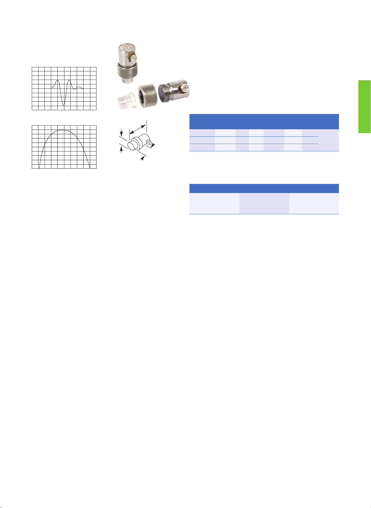
Immersion Transducers—North American Standards
Immersion Transducers—Type IPS
Immersion Transducers—Type IR
Freq.
(MHz)
Element Ø
mm in
Order Code
Freq.
(MHz)
Element Ø
mm in
Order Code
*Focus
Alpha
Series
Gamma
Series
Accessories *Focus
Alpha
Series
Gamma
Series
Accessories
2.25 6 0.25 N 122-340 222-340
Cable
BNC
118-140-012
Non-
waterproof
10.0 6 0.25
S
C
N
126-320
126-330
126-340
226-320
226-330
226-340
Cable
BNC
118-140-012
Non-
waterproof
5.0 6 0.25
S
C
N
124-320
124-330
124-340
224-320
224-330
224-340
15.0 6 0.25
S
C
N
127-320
127-330
127-340
Freq.
(MHz)
Element Ø
mm in
Order Code
Freq.
(MHz)
Element Ø
mm in
Order Code
*Focus
Alpha
Series
Gamma
Series
*Focus
Alpha
Series
Gamma
Series
2.25
6 0.25 N 122-420 222-420
5.0
6 0.25SC
N
124-400
124-410
124-420
224-400
224-410
224-420
10 0.375SC
N
132-400
132-410
132-420
232-400
232-410
232-420
10 0.375S C
N
134-400
134-410
134-420
234-400
234-410
234-420
13 0.50
S
C
N
142-400
142-410
142-420
242-400
242-410
242-420
13 0.50SC
N
144-400
144-410
144-420
244-400
244-410
244-420
* Focus: S = Spherical, C = Cylindrical, N = Non-focus. Focal length must be specified. For available focal lengths, refer to the table at the beginning of the Immersion
Transducers section. Custom configurations are available by special order.
Element Ø A B C
mm in mm in mm in mm in
6 .250 19.1 0.75 23.9 0.94 19.1 0.75
10 .375 19.1 0.75 23.9 0.94 19.1 0.75
13 .500 19.1 0.75 23.9 0.94 19.1 0.75
* Focus: S = Spherical, C = Cylindrical, N = Non-focus. Focal length must be specified. For available focal lengths, refer to the
table at the beginning of the Immersion Transducers section. Waterproof cables can be found in the Transducers Accessories
Section. Custom configurations are available by special order.
B
A
B
C
A
Element Ø A B
mm in mm in mm in
6 .250 9.7 0.38 36.8 1.45
Type IPS
Type IR
Page 37

MIG/MAG Transducers
Ultrasonic transducers for the inspection of MIG and MAG welds
using the ultrasonic transmission technique.
Tube Testing Transducers
Ultrasonic transducers for the inspection of tubes and hollow
railway axles and wheel sets.
High Temperature Transducers
Ultrasonic transducers for inspection at higher temperatures with
heat resistant delays.
High Frequency Immersion Transducers
Very high resolution immersion transducers, 25 MHz to 50 MHz.
RL Transducers
Refracted longitudinal wave angle beam transducers, single and
dual element, for inspection of coarse grain materials such as
austenitic steel pipe welds.
Boreside Arrays
Multi-element ultrasonic transducers, with water feed, for the
inspection of tubing from the ID.
ZIP Probes
"Zero Interface" delay line transducers for manual inspection of
composite materials.
35
Roller (Wheel) Transducers
Ultrasonic roller transducers and systems for the inspection of
overlapped and butt laser welds or brazed joints and welds on
tailored blanks with dry coupling.
Low Frequency Transducers
Ultrasonic transducers for the inspection of coarse materials such
as concrete, refractory bricks, stones, and wood.
Axle Transducers
Ultrasonic transducers for the inspection of railway axles and
wheel sets.
Transducer Holders
Ultrasonic transducer holders for special fixtures for the
inspection of gas bottles and tubes.
Transverse (Shear) Wave Straight Beam Transducers
Normal incidence transverse wave transducers typically used for
characterization of materials.
Spot Weld Transducers
Ultrasonic transducers with a flexible acoustic interface for
inspection of resistance welded spot welds on automotive bodies.
Transducers for Specific Applications
Special Application Transducers
GE Inspection Technologies' Application Centers provide a broad spectrum of services to users of nondestructive testing applications.
Our mission is to bring together worldwide knowledge and experience across multiple industries and modalities to help customers
quickly solve their inspection application problems.
With an unsurpassed track record, our highly skilled engineers, technicians and specialists are a key asset for our customers. Their
experience is broad, encompassing many NDT modalities and many industry segments—from the development of a radiographic
solution to inspect aerospace parts on the manufacturing floor to the design of customized ultrasound transducers or eddy current
probes for field inspection in the power, oil, gas and automotive industries.
New materials, manufacturing processes, and joining technologies often require customized ultrasonic transducers and accessories,
designed specifically for the particular application. We offer a wide range of special application transducers, some of which are shown on
these pages. Our special transducer teams are ready to address new application problems quickly and effectively. For more information
and an inquiry form, visit GE Inspection Technologies on the Internet at www.ge.com/inspectiontechnologies.
Page 38

36
Phased Array Transducers
Small and Mid-Sized Phased Arrays for General Angle and
Straight Beam Applications
GE Inspection Technologies manufactures a wide variety of phased array transducers for use with Phasor and other instruments. Phasor
transducers with the Dialog feature recognize physical connection and automatically download transducer information to Phasor. More
information on our full range of phased array transducers is available at www.ge.com/inspectiontechnologies.
Phased Array for Scanning and Wide Area Coverage,
Immersion or Delay Line
Applications
• Power: General weld inspection, austenitic welds, pressure
vessels and piping, turbine blades, rotors
• Oil and Gas: Pipeline girth welds, tanks, general weld inspection
• Aerospace: Weld inspection, landing gear
• Automotive: Axles, shafts, spindles, brake discs, wheels
• General: Welds, forgings, castings, tubular goods, bridges and
structures
Features and Benefits
• Electronic control of beam angle, focus, and scanning index
• Eliminate multiple inspections with fixed angle and fixed focus
probes.
• Inspect hard to access areas from a single contact point.
• Replaceable angle beam wedges and 0° delay lines, flat or curved
• Probes with internal wedges and delay lines are also available.
Typical Specifications (Others Available Upon Request)
Applications
• Power Generation: Pressure vessels, piping
• Oil and Gas: Piping, tanks
• Aerospace: Composite delamination and disbond, weld
inspection, landing gear
• Transportation: Composite delamination and disbond, plates
• General: Large area scanning, plate, bar, tubular goods, inline thickness measurement
Features and Benefits
• Electronic control of beam angle, focus, and scanning index
• Reduce set-up and scan times.
• Increase sensitivity and signal-to-noise ratio with electronic
focusing.
• Reduce or eliminate mechanical and manual manipulation.
• Use immersion method or with replaceable delay line.
Typical Specifications (Others Available Upon Request)
Frequency
(MHz)
Element Count Pitch mm (in) Elevation mm (in)
1.0 16, 32, 64, 128 1 to 3 (.04 to .12) 10 to 25 (0.4 to 1.0)
1.5 16, 32, 64, 128 0.75 to 3 (.03 to .12) 10 to 25 (0.4 to 1.0)
2.25 16, 32, 64, 128 0.5 to 2 (.02 to .08) 6 to 20 (0.25 to 0.8)
3.5 16, 32, 64, 128 0.5 to 2 (.02 to .08) 6 to 20 (0.25 to 0.8)
5.0 16, 32, 64, 128 0.25 to 1.5 (.01 to .06) 6 to 20 (0.25 to 0.8)
7.5 16, 32, 64, 128 0.25 to 1 (.01 to .04) 6 to 16 (0.25 to 0.63)
Frequency
(MHz)
Element Count Pitch/mm (in) Elevation/mm (in)
1.0 32, 64, 128 1 to 3 (.04 to .12) 10 to 25 (0.4 to 1.0)
1.5 32, 64, 128 0.75 to 3 (.03 to .12) 10 to 25 (0.4 to 1.0)
2.25 32, 64, 128 0.5 to 2 (.02 to .08) 6 to 20 (0.25 to 0.8)
3.5 32, 64, 128 0.5 to 2 (.02 to .08) 6 to 20 (0.25 to 0.8)
5.0 32, 64, 128 0.25 to 1.5 (.01 to .06) 6 to 20 (0.25 to 0.8)
7.5 32, 64, 128 0.25 to 1 (.01 to .04) 6 to 16 (0.25 to 0.63)
10.0 32, 64, 128 0.25 to 1 (.01 to .04) 6 to 13 (0.25 to 0.5)
Page 39

37
Cables and Adapters
Cable
Type
Order Code
Length
m (ft)
Impedance
(ohms)
Transducer Instrument
CL 331 58160 2 (6.5) 50 Microdot LEMO-00
MPKLL 2 58791 2 (6.5) 50 LEMO-00 LEMO-00
MPKL 2 50486 2 (6.5) 50 LEMO-00 LEMO-1
MPKM 2 52999 2 (6.5) 50 Microdot LEMO-1
PKP 2 66709 2 (6.5) 75
LEMO-03
Waterproof
LEMO-1
PKI 2 57694 2 (6.5) 75
UHF
Waterproof
LEMO-1
PKLL 2 50326 2 (6.5) 75 LEMO-1 LEMO-1
PKTL 2 52642 2 (6.5) 50
LEMO-1
Waterproof
LEMO-1
SEKG 2 53887 2 (6.5) 50
LEMO-00
Dual Plug
2x LEMO-1
SEKL 2 50710 2 (6.5) 50 2x LEMO-00 2x LEMO-1
SEKM 2 53001 2 (6.5) 50 2x Microdot 2x LEMO-1
SEKN 2 53775 2 (6.5) 50
1x Microdot
1x Microdot, Large
2x LEMO-1
VKLL 5 50484 5 (16.4) 75 LEMO-1 Coupling LEMO-1
MD-BNC 118-140-012 1.8 (6) 50 Microdot BNC
MD-BNC 12 118-140-011 3.6 (12) 50 Microdot BNC
MMD-BNC 118-140-047 1.8 (6) 50 MMD BNC
MD/RA-BNC 118-140-033 1.8 (6) 50
Right Angle
Microdot
BNC
BNC-BNC 118-140-016 1.8 (6) 50 BNC BNC
BNC-BNC 12 118-140-021 3.6 (12) 50 BNC BNC
UHF-BNC 118-140-027 1.8 (6) 50
UHF
Non-waterproof
BNC
L1-BNC 118-140-018 1.8 (6) 50 LEMO-1 BNC
UHF/WP-BNC 118-140-013 1.8 (6) 75
UHF
Waterproof
BNC
Dual MMD-BNC 118-140-014 1.8 (6) 50 2x MMD 2x BNC
Dual MD-BNC 118-140-024 1.8 (6) 50 2x Microdot 2x BNC
Plug Type
Adaptor Type Order Code Transducer Instrument
PKLB1 53013 BNC Socket LEMO-1 Plug
PKBL1 53014 LEMO-1 Socket BNC Plug
STUHF-RA
(Right Angle)
118-560-032
UHF Plug
Waterproof
UHF Socket
Waterproof
DM-BNC
Dual)
118-560-045 D-Meter Plug 2x BNC
Plug Type
LEMO-1
LEMO-1 Coupling
LEMO-1 Waterproof
LEMO-00 Dual Plug
LEMO-00
LEMO-03 Waterproof
UHF Waterproof
UHF (non-waterproof)
BNC
Microdot, Right Angle
Microdot, Large
Microdot
MMD
Transducer Accessories
Page 40

38
Couplants
General Purpose Couplants
Couplant Type Container Size Description Order Code Features
ZG-F
2.5 kg(5.5 lb) General Purpose 50469
• Thixotropic paste
• Non-drip, washable, non-corrosive
• Temperature range -4°F to 212°F (-20°C to 100°C)
• Safety data sheet per 91/155/EEC
5 bottles
250 ml (8.5 fl oz.)
General Purpose 54558
ZGT 100 g Tube (3.5 oz.) Multigrade Couplant 50472
• Medium viscosity paste
• Water resistant, non-corrosive
• Temperature range -22°F to 480°F (-30°C to 250°C)
• Safety data sheet per 91/155/EEC
Exosen 20
3.8 liter (1 gal)
General Purpose, Medium
Viscosity
118-300-420
• Water soluble
• Non-toxic
• Non-flammable
• Antiseptic
• Non-irritating
• Rust preventative added
• Temperature range 32°F to 212°F (0°C to 100°C)
• Material Safety Data Sheet per 29 CFR 1910.1200
Case of 4
3.8 liter (1 gal)
118-300-425
18.9 liter (5 gal) 118-300-440
208 liter (55 gal) 118-300-460
Exosen 30
3.8 liter (1 gal)
General Purpose, High
Viscosity, Pourable
118-300-520
Case of 4
3.8 liter (1 gal)
118-300-525
18.9 liter (5 gal) 118-300-540
208 liter (55 gal) 118-300-560
Specialty Couplants
Couplant Type Container Size Description Order Code Notes
ZGM 100 g Tube (3.5 oz.)
High Temperature
Coupling Paste
56567
• High viscosity paste
• Solid filler melts at elevated temperature
• Specially formulated for thickness measurement on hot parts
• Temperature range 390°F to 1100°F (200°C to 600°C)
Hitempco
79 g Tube (2.8 oz.)
High Temperature
Coupling Grease
118-300-010
• High viscosity grease
• Thickness measurement and flaw detection on hot parts
• Temperature range 50°F to 550°F (10°C to 290°C)
• Material Safety Data Sheet per 29 CFR 1910.1200
12 Tubes 79 g
(2.8 oz.)
118-300-015
SLC 113 g (4 oz.)
High Viscosity, High
Attenuation
118-300-080
• Extremely high viscosity
• Allows transmission of transverse (shear) waves
• High attenuation reduces noise on rough or curved surface
• Material Safety Data Sheet per 29 CFR 1910.1200
XD-740 59 ml (2 fl oz.)
Wedge, Delay Line,
Protective Face Couplant
118-300-740
• Applied between transducer face and accessory
• Material Safety Data Sheet per 29 CFR 1910.1200
XL
236 ml (8 fl oz.)
Low Viscosity Laboratory
Couplant
118-300-820
• For smooth surface, 1.6 μm (62 μin) RMS or better
• Suitable for performance testing of ultrasonic transducers
• Material Safety Data Sheet per 29 CFR 1910.1200
3.78 liter (1 gal) 118-300-860
Page 41

39
Calibration Blocks
Calibration blocks provide known targets that produce echo indications that are used for instrument setup, transducer evaluation, and
reference for evaluating flaw size.
Calibration Blocks—European Standards
Calibration Blocks—North American Standards
Block Type (Steel) Order Code Description
K1
EN 12223
59108
• Large angle beam calibration block, 100 mm radius
• Calibrate range with an angle beam transducer
• Measure beam index point and refracted angle
K2
EN 27963/ISO 7963
50434
• Small angle beam calibration block, 25 and 50 mm radii
• Calibrate range with an angle beam transducer
• Measure beam index point and refracted angle
VW 50441
• Step block for calibrating thickness range
• Eight .039 in (1 mm) steps, .039 in (1 mm) through
.039 in (9 mm) to .315 in (8 mm)
N30 58474
• Ultrasonic reference standard
• Connect directly to flaw detector
• Produces multiple echoes at precise intervals in steel
• Check instrument gain over long time periods
Block Type
(Steel)
Order Code Description
IIW Type 1
118-540-270
• Large angle beam calibration block
• 4.0 in (101.6 mm) radius for angle beam range calibration
• Measure beam index point and refracted angle
• Also used to check resolution and sensitivity
IIW Type 2 118-540-280
• Same as IIW Type 1 with 2 in (50.8 mm) and 4 in (101.6 mm) radii for range
calibration
• Side drilled holes also added for resolution check
DSC
118-540-300
• Small block for angle beam distance and sensitivity calibration
• 1.0 in (25.4 mm) radius opposite a 3.0 in (76.2 mm) radius
• 0.375 in (9.5 mm) slot in the 3.0 in (76.2 mm) radius
• Also used to check beam index point and refracted angle
Angle Beam,
Miniature
118-540-260
• Substitute for DSC block
• 1.0 in (25.4 mm) radius opposite a 2.0 in (50.8 mm) radius
• Side drilled hole to check beam index point and refracted angle
AWS
Resolution
118-540-350
• Evaluate angle beam transducer resolution capability
• Three sets of side drilled holes for 45°, 60° and 70° angles
• Three 0.062 in (1.6 mm) diameter holes in each set of holes
NAVSHIPS Test
Block
118-540-370
• For NAVSHIPS specification 0900-006-3010, Section 6
• Distance amplitude correction, sensitivity, and flaw depth
4-Step Block
118-540-320
• Step block for calibrating thickness range
• Steps .250, .500, .750, 1.00 in (6.35, 12.70, 19.05, 25.40 mm)
5-Step Block 118-540-310
• Step block for calibrating thickness range
• Steps .100, .200, .300, .400, .500 in (2.54, 5.08, 7.62, 10.06, 12.70 mm)
Page 42

40
Transducer Kits
Our transducer kits combine the most commonly used transducers and accessories necessary for general, and some specific, ultrasonic
testing applications. Each kit includes a hard shell carrying case for easy access, convenient storage and transportation.
Transducer Kits—European Standards
Type Order Code Description Probe contents
PKS 1
57281
Coarse Grain Set K0,5S; K1SM; WRY45; WRY70; WB45-1; WSY45-4, WSY70-4
PKS 2
57282
Aircraft Set B4S; K4G; G5KB; MSEB4; K5K; CLF4; SEB10KF3; 2x MWB45-4;
MWB70-4; MWB90-4
PKS 3
57283
Steel Set B4S; SEB2; G5KB; MSEB4; MB4F; WK45-2; WK70-2; 2x
MWB45-4; MWB70-4
PKS 4
57284
Welding Set MB4S; SEB4; WB45-2; WB70-2; MWB45-2; 2x MWB45-4;
MWB60-4; 2x MWB70-4
PKS 5
57285
Casting Set B2S; SEB2; K1S; MB2S; SEB4KF8; G5KB; WB45-1; WB70-1;
MWB45-2
PKS 6
57286
Forging Set B4S; B2S; SEB2; MB4S; K2N; SEB4KF8; MB4F; WB45-2;
MWB45-4; MWB70-4
Transducer Kits—North American Standards
Basic Contact Kit
Product Order Code 118-450-020
Wide assortment for weld inspection, lamination detection, corrosion/erosion and thin gauge materials.
Qty. Product Codes Description
1 113-292-603
2.25 MHz, .63 in x .63 in AWS
Style, Single Element
1 113-242-591
2.25 MHz, .5 in MSW-QC Style, BMC
Single Element Angle Beam Probe
1 113-262-043
2.25 MHz, 1 in CR Style,
Single Element Contact Probe
1 113-544-000
5 MHz, .5 in CA211A Style,
Single Element Contact Probe
1 113-252-240
2.25 MHz, .75 in PFCR Style,
Single Element Membrane Probe
Qty. Product Codes Description
1 113-527-660
15 MHz, .25 in ALPHA 2 DFR Style,
Single Element Delay Line Probe
1 113-292-751
2.25 MHz, .5 in x .5 in DU-F Style,
Dual Element Contact Probe
1 113-224-681
5 MHz, .25 in RC Style,
Dual Element Contact Probe
1 C-012
BNC-MD Coaxial Cable
1 C-016
BNC-BNC Coaxial Cable
1 C-024
BNC-MD Dual Coaxial Cable
1 C-088
BNC-RC Dual Coaxial Cable
Qty. Product Codes Description
1 D-050
Delay Lines for 113-527-660
(10 pcs.)
1 PK-140
Protective Membrane Kit for
113-252-240 PFCR probe.
1 W-104, 106
45° and 70° Lucite Wedge
1
W-211, 212, 213 45°, 60° and 70° Lucite Wedge
1 XD-740
Wedge/Delay Line Couplant
1 118-540-198
Calibration Block .1 in–.5 in
1 118-800-025
Diced Foam Carrying Case
Qty. Product Codes Description
1 113-292-603
2.25 MHz, .63 in x .63 in AWS Style,
Single Element Angle Beam Probe
1 113-292-601
2.25 MHz, .63 in x .75 in AWS Style,
Single Element Angle Beam Probe
1 113-292-604
2.25 MHz, .75 in x .75 in AWS Style,
Single Element Angle Beam Probe
1 113-262-043
2.25 MHz, .1 in dia. CR-RHP,
L-Wave Contact Probe
1 W-104
45° Lucite Wedge
1 W-105
60° Lucite Wedge
1 W-106
70° Lucite Wedge
1 C-016
BNC-BNC Coaxial Cable
1 B-196
DSC Reference Standard
1 XL-820
8 oz. Couplant
1 118-800-025
Diced Foam Carrying Case
Qty. Product Codes Description
1 113-544-000
5 MHz, .5 in dia. CA211A Style,
Single Element Contact Probe
1 113-262-043
2.25 MHz, 1 in dia. CR Style,
Single Element Contact Probe
1 113-527-660
15 MHz, .25 in Alpha 2 DFR Style,
Delay Line Probe
1 113-224-700
5 MHz, .25 in dia. ADP Style,
Dual Element Probe
1 113-244-591
5 MHz, .5 in dia. MSW-QC Style,
Benchmark Angle Beam Probe
2 W-211
45° Lucite Wedge
2 W-212
60° Lucite Wedge
2 W-213
70° Lucite Wedge
2 C-016
BNC-BNC Coaxial Cable
2 C-012
BNC-MD Coaxial Cable
1 118-540-198
5 Step Reference Standard,
1 in-.5 in
1 XL-820
8 oz. Couplant
1 118-800-025
Diced Foam Carrying Case
Qty. Product Codes Description
1 113-294-642
5 MHz, 70° ABFP-SM,
Single Element Angle Beam Probe
1 113-216-585
10 MHz, .125 in SMSWS Style,
Single Element Angle Beam Probe
1 113-294-600
5 MHz, 5 in x 1 in SWS Style,
Single Element Angle Beam Probe
1 113-224-591
5 MHz, .25 in MSWQC Style,
Benchmark Angle Beam Probe
1 118-540-196
DSC Reference Standard
1 C-047
BNC-MMD Coaxial Cable
1 C-016
BNC-BNC Coaxial Cable
1 C-012
BNC-MD Coaxial Cable
1 ea. W-120, 122
45° and 70° Lucite Wedge
1 ea. W-015, 017
45° and 70° Lucite Wedge
1 ea. W-201, 202, 203
45°, 60° and 70° Lucite Wedge
1 XL-820
8 oz. Couplant
1 118-800-025
Diced Foam Carrying Case
Basic AWS Weld Inspection Kit
Order Code 118-450-500
Transducers and accessories
for testing weldments to
specification AWS D1.1.
Multi-Purpose Contact Kit
Order Code 118-450-510
Commonly used transducers for a variety
of angle beam, lamination, corrosion,
general flaw, and thickness testing.
Basic Angle Beam Kit
Order Code 118-450-030
Assortment for weld and other angle
beam inspections.
Page 43

41
Transducer Certification
European Standards
Each delivered probe is subjected to a very strict quality test that
makes certain all probes of the same type identically evaluate
flaws. The corresponding probe data sheet contains proof of the
data reliability. We store the data of every numbered probe for a
number of years, enabling probe certificates (PZ) to also be
produced at a later date.
North American Standards
Certificate Order Code Description
PZ-E 57682 Waveform and frequency spectrum for
standard catalog flaw transducers,
including amplitude, frequency, bandwidth,
and pulse duration
PZ-EN 59969 Detailed certificate of calibration according
to standard EN 12668-2, "Non-destructive
testing - Characterization and verification of
ultrasonic examination equipment Part 2: Probes", ratified by European
Committee for Standardization (CEN)
Certificate Order Code Description
Waveform/
Frequency
113-900-911 Waveform and frequency spectrum for
standard catalog flaw transducers,
including amplitude, frequency,
bandwidth, and pulse duration
Beam Profile 113-900-913 Plot is made by moving the transducer
across a ball or rod reflector in an
immersion tank. The beam profile gives
the relative intensity and width of the
sound beam at a given distance from the
transducer face.
Transducer Certificate PZ-E
Transducer Certificate PZ-EN
Waveform/Frequency Certificate
Beam Profile
Page 44

42
Page 45

43
Material Longitudinal
Velocity
Shear Velocity Acoustic
Impedance
in/s x 10
6
km/s
in/s x 10
6
km/s MRayl
Air .013 .33 – – .0004
Aluminum .25 6.3 .12 3.1 17.0
Aluminum Oxide .39 9.9 .23 5.8 32.0
Beryllium .51 12.9 .35 8.9 23.0
Boron Carbide .43 11.0 – – 26.4
Brass .17 4.3 .08 2.0 36.7
Cadmium .11 2.8 .059 1.5 24.0
Copper .18 4.7 .089 2.3 41.6
Glass (Crown) .21 5.3 .12 3.0 18.9
Glycerin .075 1.9 – – 2.42
Gold .13 3.2 .047 1.2 62.6
Ice .16 4.0 .08 2.0 3.5
Inconel .22 5.7 .12 3.0 47.2
Iron .23 5.9 .13 3.2 45.4
Iron (Cast) .18 4.6 .10 2.6 33.2
Lead .085 2.2 .03 .7 24.6
Magnesium .23 5.8 .12 3.0 10.0
Mercury .057 1.4 – – 19.6
Molybdenum .25 6.3 .13 3.4 64.2
Monel .21 5.4 .11 2.7 47.6
Neoprene .063 1.6 – – 2.1
Material Longitudinal
Velocity
Shear Velocity Acoustic
Impedance
in/s x 10
6
km/s
in/s x 10
6
km/s MRayl
Nickel .22 5.6 .12 3.0 49.5
Nylon, 6-6 .10 2.6 .043 1.1 2.9
Oil (SAE 30) .067 1.7 – – 1.5
Platinum .13 3.3 .067 1.7 69.8
Plexiglass .11 2.7 .043 1.1 3.1
Polythylene .07 1.9 .02 .5 1.7
Polystyrene .093 2.4 .04 1.1 2.5
Polyurethane .070 1.9 – – 1.9
Quartz .23 5.8 .087 2.2 15.2
Rubber, Butyl .07 1.8 – – 2.0
Silver .14 3.6 .06 1.6 38.0
Steel, mild .23 5.9 .13 3.2 46.0
Steel, stainless .23 5.8 .12 3.1 45.4
PTFE .06 1.4 – – 3.0
Tin .13 3.3 .07 1.7 24.2
Titanium .24 6.1 .12 3.1 27.3
Tungsten .20 5.2 .11 2.9 101.0
Uranium .13 3.4 .08 2.0 63.0
Water .0584 1.48 – – 1.48
Zinc .17 4.2 .09 2.4 29.6
dB Ratio dB Ratio dB Ratio dB Ratio
0 1.00:1 5 1.78:1 11 3.55:1 17 7.08:1
.5 1.06:1 6 2.00:1 12 3.98:1 18 7.94:1
1 1.12:1 7 2.24:1 13 4.47:1 19 8.91:1
2 1.26:1 8 2.51:1 14 5.01:1 20 10.00:1
3 1.41:1 9 2.82:1 15 5.62:1 40 100.00:1
4 1.58:1 10 3.16:1 16 6.31:1 60 1000.00:1
Near Field Length
D2F/4C or D2/4λ
Beam Spread
SINγC/DF x 1.22 or 1.22λ/D
Snell’s Law SINα/ SINβ = C1/C
2
Skip Distance 2T x TANβ
V-Path 2T/COSβ
Surface Distance (Projected) S.P. x SINβ
Depth (1st Leg) S.P. x COSβ
Depth (2nd Leg) 2T - (S.P. x COSβ)
Depth (3rd Leg) (S.P x COSβ) - 2T
Wavelength C/F
Frequency C/λ
Acoustic Impedance Z = C x d
% of Reflected Sound Pressure Rp = (Z2- Z1)/(Z2+ Z1)
Coefficient of Transmission Tp = 2Z2/(Z2+ Z1)
Total Beam Width TBW = (Depth - N) (2TANγ) +
T x Element Diameter
Transit Time TT = 2T/C
Center Frequency Fc = (F1+ F2)/2
% Bandwidth (F1- F2)/Fcx 100%
Q Factor Fc/(F1- F2)
Distance Speed x Time
RPM Speed/Circumference
Maximum Scanning Speed (x, y)
(Min. Flaw Length + EBW) x PRR
Maximum Scanning Speed
(polar)
RPM x Diameter x Clock
interval (ft per min.)
dB Difference 20 Log (A1/A2)
dB Ratio Inv log dB/20
Water Equivalent = (Steel)
WE = F (water) x
(C(water))/(C(steel)) (F = Focal
length)
MAXß SIN-1 (ID/OD)
Focal Length R = F (n - 1)/n
Cylinder Offset Technique
Offset (X) = Outside Radius x SINa
Tables and Formulas
Velocity and Acoustic Impedance of Common Materials
Useful Formulas
dB vs. Amplitude Ratio Chart
Symbol Key
λ = Wavelength
D = Probe Diameter
F = Probe Frequency
C = Acoustic Velocity
d = Density
α = Incident Angle
ß = Refracted Angle
T = Part Thickness
S.P. = Sound Path
N = Near Field
γ = Divergence 1/2
Angle
Element Diameter
Frequency
(MHz)
mm
25.4
(in)
(1.0)
mm
19.1
(in)
(0.75)
mm
12.7
(in)
(0.50)
mm
6.3
(in)
(0.25)
1.0 109.2 (4.3) 61 (2.4) 27.2 (1.07) 6.8 (0.27)
2.25 243.8 (9.6) 137.1 (5.4) 61.0 (2.4) 15.3 (0.60)
5.0 543.5 (21.4) 304.8 (12.0) 137.1 (5.4) 33.0 (1.3)
10.0 1092.2 (43) 609.6 (24) (271.8) (10.7) 68.6 (2.7)
To find approx. length in steel, divide the above values by 4.
Near Field Length (N) in Water
Page 46

GE Sensing & Inspection Technologies
couples a legacy of more than 130 years
of GE leadership and innovation with
world-class technology from the
leading names in ultrasonic
nondestructive testing—AGFA NDT,
Krautkramer and Nutronik.
Page 47

GE
Sensing & Inspection Technologies
GE Sensing & Inspection Technologies provides
technology-driven inspection solutions that deliver
productivity, quality and safety. We design,
manufacture and service ultrasonic, remote visual,
radiographic and eddy current equipment to
inspect, monitor and test materials and equipment
without disassembling, deforming or damaging
them.
We offer specialized products and services that will
help improve productivity in a wide range of
industries including aerospace, power generation, oil
and gas, automotive and metals.
Ultrasonic
Radiography
Hardness Testing
Eddy Current
Remote Visual
Metrology
Software
 Loading...