

Page 1
PocketMIKE
Operating Manual
©2004 GE Inspection Technologies, LP
50 Industrial Park Road
Lewistown, PA 17044
Phone: +1 (717) 242-0327
Fax: +1 (717) 242-2606
www.GEInspectionTechnologies.com
021-002-279
GE Inspection Technologies Systems GmbH
Robert-Bosch-Straße 3
D – 50354 Hürth
Phone: +49 (0) 2233 601111
Fax.: +49 (0) 2233 601402
Page 2

Page 3

PocketMIKE
Operating Manual version 2.0
Page 4

Page 5

Important Notice
The following information must be read and understood by any user of
a GE Inspection Technologies ultrasonic thickness gauge. Failure to
follow these instructions can lead to errors in thickness measurements
or other test results. Decisions based on erroneous results can, in turn,
lead to property damage, personal injury or death.
General Warnings
Proper use of ultrasonic test equipment requires three essential elements:
◆ Selection of the correct test equipment.
◆ Knowledge of the specific “test application requirements.”
◆ Training on the part of the instrument operator.
This operating manual provides instruction in the basic set up and
operation of the GE Inspection Technologies thickness gauge.
There are, however, additional factors which affect the use of ultrasonic
test equipment. Specific information regarding these additional factors
is beyond the scope of this manual. The operator should refer to textbooks on the subject of ultrasonic testing for more detailed information.
Operator Training
Operators must receive adequate training before using ultrasonic test
equipment. Operators must be trained in general ultrasonic testing
procedures and in the set up and performance required by a particular
test. Operators must understand:
◆ Soundwave propagation theory.
◆ Effects of the sound velocity of the test material.
◆ Behavior of the sound wave where two different materials
are in contact.
◆ Areas covered by the sound beam.
PocketMIKE Operating Manual Page i
Page 6

More specific information about operator training, qualification,
certification, and test specifications is available from various technical
societies, industry groups, and government agencies.
Testing Limitations
In ultrasonic testing, information is obtained only from within the limits
of the sound beam. Operators must exercise great caution in making
inferences about the test material outside the limits of the sound beam.
For example, when testing large materials it may be impossible or
impractical to inspect the entire test piece. When a less-than-complete
inspection is to be performed, the operator must be shown the specific
areas to inspect. Inferences about the condition of areas not inspected,
based on data from the evaluated areas, should only be attempted by
personnel fully qualified and trained in applicable standards of statistical evaluation. In particular, materials subject to erosion or corrosion, in
which conditions can vary significantly in any given area, should only
be evaluated by fully trained and experienced operators.
Sound beams reflect from the first interior surface encountered. Because of part geometry and overlapped flaws or overlapped surfaces,
thickness gauges may measure the distance to an internal flaw rather
than to the back wall of the material. Operators must take steps to
ensure that the entire thickness of the test material is being examined.
Ultrasonic Thickness Measurement
Critical Operating Procedures
The following operating procedures must be observed by all users of
ultrasonic thickness gauges in order to minimize errors in test results.
1. Calibration of Sound Velocity
The principle of operation of an ultrasonic thickness gauge is that the
instrument measures the time of flight of an ultrasonic pulse through
the test piece and multiplies this time by the sound velocity of the
material. Thickness measuring error is minimized by ensuring that the
sound velocity to which the instrument is calibrated is the sound
Page ii PocketMIKE Operating Manual
Page 7

velocity of the material being tested. Actual sound velocities in materials often vary significantly from the values found in published tables.
In all cases, best results are obtained if the instrument is calibrated on a
velocity reference block made from the same material as the test piece;
this block should be flat and smooth and as thick as the maximum
thickness of the test piece.
Operators should also be aware that the sound velocity may not be
constant in the material being tested; heat treating, for example, can
cause significant changes in sound velocity. This must be considered
when evaluating the accuracy of the thickness provided by this instrument. Instruments should always be calibrated before testing, and the
calibration should be checked after testing, to minimize testing errors.
2. Probe Zero Procedure
Probe zeroing is the process of measuring the time of flight of sound
through the transducer. The transducer time of flight is then automatically removed from each measurement so that only the test piece time
of flight is used to calculate and display the thickness value. The probe
zeroing process is performed automatically while the probe is coupled.
3. Effects of Temperature on Calibration
Temperature variations change the sound velocity of materials and
transducer delay lines and, therefore, calibrations. All calibrations
should be performed on-site, and with test blocks at the same
temperature as the test piece, to minimize errors due to temperature
variations.
4. Transducer Selection
The transducer used in testing must be in good condition without
noticeable wear of the front surface. Badly worn transducers will have a
reduced effective measuring range. The specified range of the transducer must include the complete range of thicknesses to be tested. The
temperature of the material to be tested must be within the transducer’s
temperature range.
PocketMIKE Operating Manual Page iii
Page 8

5. Use of Couplants
Operators must be familiar with the use of ultrasonic couplants. Testing
skills must be developed so that couplant is used and applied in a
consistent manner to minimize variations in couplant layer thickness
and errors in test results. Calibration and actual testing should be
performed under similar coupling conditions, using a minimum amount
of couplant and applying consistent pressure on the transducer.
6. Doubling
Ultrasonic thickness gauges will, under certain conditions, display
readings which are twice (or, in some cases, three times) the actual
material thickness being measured. This effect, commonly known as
“doubling,” can occur below the minimum specified range of the
transducer. If the transducer being used is worn, doubling is possible at
a thickness greater than the minimum of the specified range.
When using a new transducer, any reading which is less than twice the
minimum specified range of the transducer may be a “doubled” reading, and the thickness of the material being tested should be verified by
the use of other methods. If the transducer shows any sign of wear,
doubling may occur at a thickness greater than twice the minimum of
the specified range. This thickness should be determined by calibrating
the PocketMIKE on reference blocks that represent the complete range
of possible thicknesses that may be encountered in testing. This is
particularly important when the test piece is being ultrasonically
measured for the first time or in any case where the history of thickness
of the test specimen is unknown.
Physics of Ultrasound
These instruments operate on the ultrasonic pulse-echo principle,
similar to sonar. A short ultrasonic pulse is transmitted into the part by a
probe (transducer). The pulse travels through the material under test
until it encounters an interface, that is a material with substantially
different physical characteristics, such as air or liquid, at the back
surface of the part. At the interface, the pulse is reflected back to the
probe.
Page iv PocketMIKE Operating Manual
Page 9
The time needed for the pulse to make this round trip is divided by two
and multiplied by the sound velocity of the material under test. The
result is the thickness of the material.
The figure below illustrates the pulse-echo principle of ultrasonic
thickness measurement.
Dual
Probe
Acoustic
Zero
Backwall Echo
Dual Element Thickness Measurement
V-Path of
Pulse
PocketMIKE Operating Manual Page v
Page 10

Page vi PocketMIKE Operating Manual
Page 11

Contents
Chapter 1: Getting Started ................................................................... 1
1.1 Installing the Battery ...................................................................................... 1
1.2 Powering On the Instrument ......................................................................... 2
Chapter 2: Quick Help for Interpreting the Keypad and
Display Screen ..................................................................................... 3
2.1 Keypad Operations ......................................................................................... 4
2.2 Display Indicators ........................................................................................... 5
2.3 Types of Display Screens ................................................................................ 6
Chapter 3: Setting Up the Instrument ................................................. 9
3.1 Adjusting the Display’s Brightness (Backlight) .......................................... 10
3.2 Thickness Calibration ................................................................................... 11
3.3 Velocity Calibration ...................................................................................... 12
3.4 Setting the Measurement Units and Resolution ......................................... 13
3.5 Reversing the Display’s Orientation ........................................................... 13
3.6 Replacing the Probe ...................................................................................... 14
3.7 Disabling Instrument Adjustment Controls ............................................... 15
3.8 Rotating the Display ..................................................................................... 15
Chapter 4: Measuring Thickness ...................................................... 17
Chapter 5: Specifications and Declaration ....................................... 19
5.1 Specifications ................................................................................................. 19
5.2 EC Declaration of Conformity ..................................................................... 20
Chapter 6: Application Considerations ............................................. 21
6.1 Material Consistency in Test Specimen ...................................................... 21
6.2 Flaws in the Specimen Being Tested ............................................................ 22
6.3 Condition of the Test Specimen’s Surface................................................... 22
6.4 Test Specimens with Curved Surfaces ........................................................ 22
Chapter 7: Troubleshooting Guide ................................................... 25
Chapter 8: Warranty and Repair ....................................................... 27
8.1 Warranty ........................................................................................................ 27
8.2 Service ............................................................................................................ 29
Chapter 9: Appendix .......................................................................... 31
Index ................................................................................................... 33
PocketMIKE Operating Manual Page vii
Page 12

Page viii PocketMIKE Operating Manual
Page 13

Getting Started
To begin using your PocketMIKE, you need only install a battery in
the instrument and power it on.
1.1 Installing the Battery
◆ The instrument is powered by one “AA” size Alkaline
battery.
◆ An alkaline battery will provide approximately 80 hours of
service life.
◆ Replace the battery as soon as possible after the low battery
indicator (
To install the battery, refer to Figure 1-1 and follow these steps:
) appears on the instrument’s display.
Step 1—Unscrew the probe locking ring and remove the probe from its
sealed position.
Step 2—Insert one “AA” battery in the instrument. Make sure the
battery poles are oriented as shown in Figure 1-1. The instrument will
not function if the battery is inserted incorrectly.
Step 3—Reinstall and finger tighten the probe locking ring until the
ring is seated against the instrument body.
PocketMIKE Operating Manual Page 1
Page 14
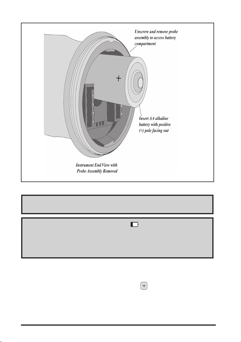
Figure 1-1—Battery Replacement
NOTE: Avoid using tools which may over-tighten the probe locking
ring.
NOTE: When the low battery indicator ( ) lights, replace the battery
as soon as possible. When the battery is too weak for reliable operation,
the instrument automatically powers off. Instrument settings are saved
and restored when batteries are replaced and the instrument is again powered on.
1.2 Powering On the Instrument
To power on the instrument, simply press . Pressing and holding
this key for more than three seconds, when the instrument is on, will
cause it to power off. If the instrument is uncoupled and no keys are
pressed for three minutes, the instrument will automatically power off.
Page 2 PocketMIKE Operating Manual
Page 15
Quick Help for
Interpreting the Keypad
and Display Screen
PocketMIKE controls and settings are displayed in the instrument’s
screen and adjusted using various combinations of key presses. This
chapter identifies the display screen’s features, the keypad functions,
and the general display structure. Topics covered include:
◆ Keypad Operations (section 2.1)
◆ Display Indicators (section 2.2)
◆ On-Screen Menu Structure (section 2.3)
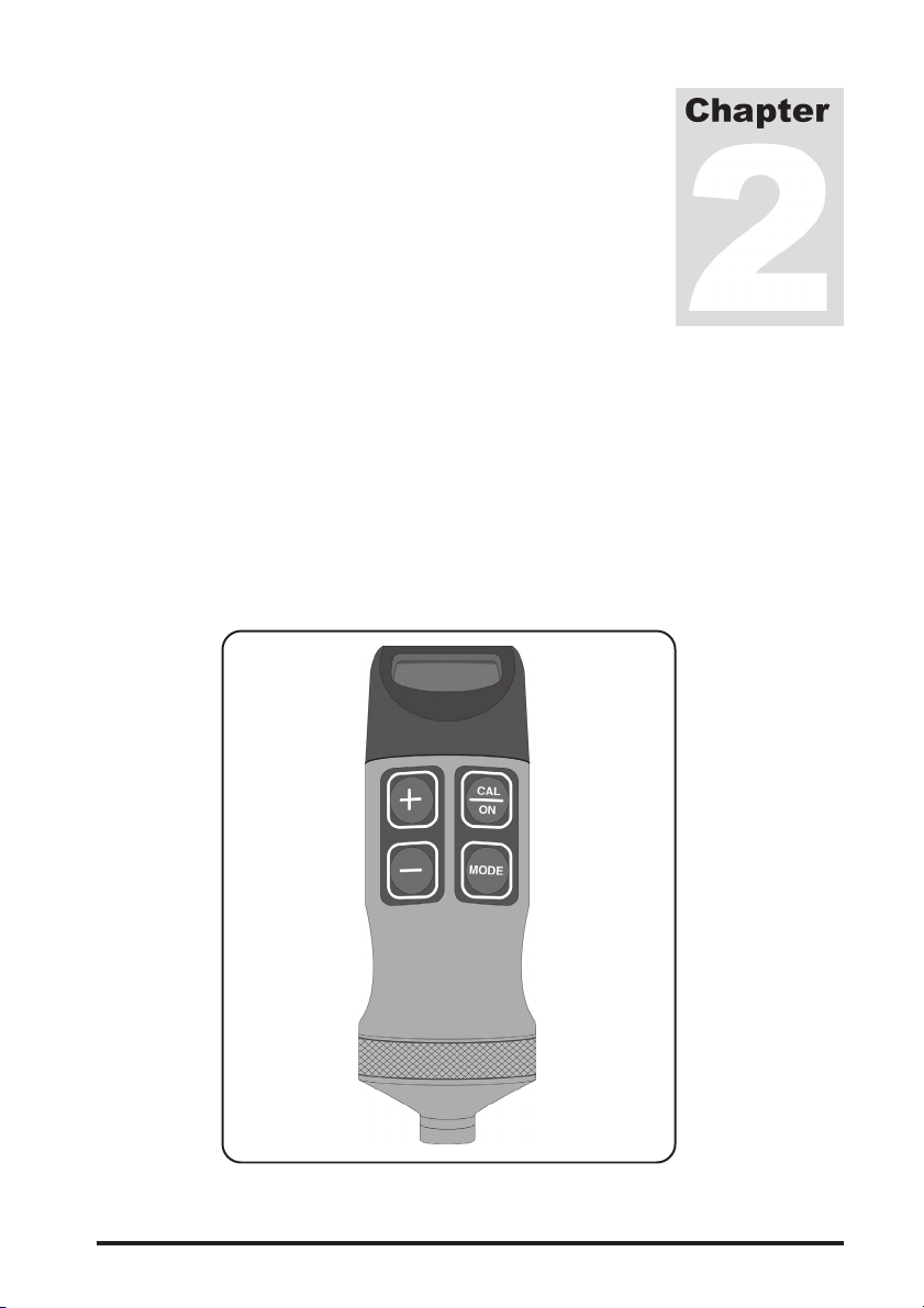
FIGURE 2-1—PocketMIKE
PocketMIKE Operating Manual Page 3
Page 16

2.1 Keypad Operations
The following is a brief summary of each key’s function. For more
complete information, refer to the referenced manual section.
Powers the instrument on and off (section 1.2)
Launches and ends the thickness calibration
process (section 3.2)
Reverses display orientation (section 3.5)
Changes on-screen values when in thickness and
velocity calibration modes (sections 3.2 and 3.3)
Changes setting when in Backlight Adjustment
mode (section 3.1)
Reverses display orientation (section 3.5)
Changes on-screen values when in thickness and
velocity calibration modes (sections 3.2 and 3.3)
Changes setting when in Backlight Adjustment
mode (section 3.1)
and Simultaneous pressing of these keys selects
measurement units and resolution (section 3.4)
Simultaneous pressing and HOLDING these keys
activates and deactivates SAFE mode in which most
instrument controls are disabled (section 3.7)
Launches and ends the Velocity Calibration process
and activates Backlight Adjustment mode
(sections 3.3 and 3.1)
Page 4 PocketMIKE Operating Manual
Page 17

2.2 Display Indicators
The PocketMIKE display (Figure 2-2) includes indicators (icons)
around its perimeter and text or numerical values in its center. Indicators and other display contents vary in response to instrument settings,
key presses, and measurement status. The following is a summary of
display indicators. For more complete information, refer to the
referenced manual section.
FIGURE 2-2—Each of these screen
indicators are displayed only under
certain conditions.
Indicates instrument is in Thickness Measurement
mode when display is not inverted (chapter 4).
Thickness Calibration mode is in process
(section 3.2).
Velocity Calibration mode is in process
(section 3.3).
Indicates instrument is in Backlight Adjustment
mode (section 3.1).
Indicates a low battery condition (section 1.1).
Displayed when probe is coupled (chapter 4).
Unit of measurement set to inches (Imperial Units)
(section 3.4).
Unit of measurement set to millimeters (Metric
Units) (section 3.4).
PocketMIKE Operating Manual Page 5
Page 18

SAFE Control lockout is activated, instrument controls are locked
out (section 3.7).
donE Displayed when lockout mode has been disabled (section 3.7).
HOT Instrument’s internal temperature has exceeded defined
limits (chapter 4)
FAIL (Diagnostic Message displayed after power-up)
Instrument memory is corrupted. Return for service.
CAL Calibration mode for sound velocity is active. Thickness
may be calibrated.
2.3 Types of Display Screens
The PocketMike offers three general display screen modes, similar to
the three shown below:
◆ Thickness Measurement Display (Figure 2-3)
◆ Calibration Mode (Figure 2-4)
◆ Backlight Adjustment Mode (Figure 2-5)
FIGURE 2-3—In thickness measurement
mode,
upper edge. Other on-screen indicators
are shown here. See Chapter 4 for more
details related to Thickness Measurement
mode and related display indicators.
Page 6 PocketMIKE Operating Manual
appears along the display’s
Page 19

FIGURE 2-4—While the calibration process is underway,
appears (and flashes) along the display’s edge. The calibration
display varies depending on whether velocity or thickness
calibration mode is indicated. See sections 3.2 and 3.3 for more
details related to instrument calibration.
FIGURE 2-5—Pressing twice (when operating in Thickness
Measurement mode) launches the Backlight Adjustment mode.
Pressing
or sets backlight to On, OFF, or Auto (section 3.1).
PocketMIKE Operating Manual Page 7
Page 20

Page 8 PocketMIKE Operating Manual
Page 21

Setting Up the
Instrument
Instrument settings can be configured to match your test conditions.
This chapter explains how to configure the instrument to measure
thickness. Topics covered include:
◆ Adjusting Display Brightness or Backlighting (section 3.1)
◆ Thickness Calibration (section 3.2)
◆ Velocity Calibration (section 3.3)
◆ Setting the Measurement Units and Resolution
(section 3.4)
◆ Reversing the Instrument’s Display Orientation (section 3.5)
◆ Replacing a Probe (section 3.6)
◆ Disabling All Adjustment Controls (section 3.7)
◆ Rotating the Display (section 3.8)
NOTE: Prior to setting up an instrument, a battery must be installed and
the instrument must be powered on. Refer to Chapter 1 for information
on installing a battery and turning the instrument on.
NOTE: Before using this instrument, read the “Important Notices” at
the beginning of this manual, and Chapter 6 — Application Consider-
ations, for important information on test conditions that affect measurement results.
PocketMIKE Operating Manual Page 9
Page 22

3.1 Adjusting the Display’s Brightness
(Backlight)
The instrument’s backlight feature illuminates the display to improve
visibility when operating in low light conditions. Note that using the
backlight feature reduces battery life.
Press
When this mode is active,
When Auto mode is selected, the backlight automatically illuminates
each time a key is pressed or when the probe is coupled. The backlight
remains illuminated for approximately 4 seconds after which it automatically extinguishes. It will re-illuminate with the next key press or
coupling.
one or two times to activate the Backlight Adjustment mode.
appears in the display’s corner. Press
or to select between the following backlight modes:
◆ On
◆ OFF
◆ Auto
Page 10 PocketMIKE Operating Manual
Page 23

3.2 Thickness Calibration
NOTE: Worn, cracked, or otherwise damaged probe tips will affect the
accuracy of thickness measurements. Refer to section 3.6 for information on probe replacement.
The instrument offers two calibration modes, thickness and velocity
(section 3.3). To launch thickness calibration mode, press
the instrument’s display shows the
throughout the calibration process,
indication. Note that
appears (and flashes) along
the display’s upper edge. Figure 3-1 illustrates the displayed parameters and key presses required to navigate through the thickness
calibration process. Note that calibration should be performed with the
instrument set to its highest resolution.
NOTE: Calibration standards of known thickness should be of the same
material, sound velocity, and curvature of the material being tested. Best
results are achieved with a standard that is slightly thicker than the thickest expected test piece.
anytime
Uncouple when reading is stable then
press
nominal value.
FIGURE 3-1—Thickness Calibration Procedure
PocketMIKE Operating Manual Page 11
or to adjust reading to
Page 24

3.3 Velocity Calibration
The user can directly specify the acoustic velocity of the material
being tested. To launch velocity calibration mode, press
the instrument’s display shows
currently set acoustic velocity (in units of inches-per-microsecond or
meters-per-second depending on units-of-measurement settings).
. The instrument displays the
anytime
Note that throughout the velocity calibration process,
(and flashes) along the display’s upper edge. Figure 3-2 illustrates the
displayed parameters and key presses required to navigate through the
velocity calibration process.
NOTE: A thickness standard is not required to perform a velocity calibration. However, following a velocity calibration the instrument’s accuracy should be checked using a sample of known thickness and with a
sound velocity that matches the user-inputted value. A table of approximate sound velocities for various materials can be found in Chapter 9.
appears
FIGURE 3-2—Velocity Calibration Procedure
Page 12 PocketMIKE Operating Manual
Page 25

3.4 Setting the Measurement Units
and Resolution
Measured thickness can be displayed in either metric or imperial units
and to one of two levels of resolution. Available measurement units
and resolution include:
— 0.00 inches — 0.0 mm
— 0.000 inches — 0.00 mm
Notice that the active units of measurement are indicated by
, which appear along the bottom of the display. To select the unit
and resolution of measurement. Press
anytime
also determine the units in which acoustic velocity is displayed.
NOTE: Selecting a resolution setting of 0.0 mm or 0.00 inch may
increase battery life.
is displayed. The unit of measurement selected will
and simultaneously
3.5 Reversing the Display’s
Orientation
The displayed thickness and units of measurement ( or ) can
be reversed (displayed upside down) to allow for easy display-screen
reading with the instrument in either the probe up or probe down
orientation. To reverse the display, simply press
instrument’s display shows
return the display to its original orientation. Note that the orientation
of other on-screen indicators do not change. A press of the key
return the display to its normal orientation and enter velocity calibration mode.
. A second press of either key will
or anytime the
or
will
PocketMIKE Operating Manual Page 13
Page 26

3.6 Replacing the Probe
Worn, cracked, or otherwise damaged probe (transducer) contact
surfaces can affect measurement accuracy. The probe and locking ring
are replaced as an assembly. Refer to Figure 3-3 for the probe replacement procedure. Always recalibrate the instrument after the probe is
replaced or removed.
FIGURE 3-3—Probe Replacement
Page 14 PocketMIKE Operating Manual
Page 27

3.7 Disabling Instrument Adjustment
Controls
The control lockout feature disables all instrument controls (except
Power Off and Display Reversal). To activate the lockout, simultaneously press and hold
the word “SAFE” appears on the display screen. When lockout mode
is activated, the instrument calibration, units of measurement, and
backlight setting can not be adjusted. This mode is disabled by repeating the simultaneous key press and is indicated when “donE” appears
on the display. Note that powering the instrument off and back on does
not disable the lockout mode.
and for longer than three seconds until
3.8 Rotating the Display
The plastic display housing on the top of the PocketMike can be
rotated through 180 degree of motion. To rotate the display housing
grasp the PocketMike in one hand while gently turning the display
housing. Do not attempt to turn the display housing past its limits or
damage could result.
PocketMIKE Operating Manual Page 15
Page 28

Page 16 PocketMIKE Operating Manual
Page 29

Measuring Thickness
The PocketMIKE measures thickness in units of inches or mm. Read
the following notices and instructions before measuring thickness.
NOTE: The instrument is designed to measure materials with surface
temperatures of up to 100°C. However, the instrument’s internal electronics should not be allowed to reach temperatures above 60°C for extended periods of time. When internal instrument temperature reaches
60°C, the instrument displays the word “Hot.” This warning will remain
until the instrument’s internal temperature drops below 55°C. When internal temperature reaches 85°C, the HOT warning is momentarily displayed, than the instrument is automatically powered off.
NOTE: Before using this instrument, read the “Important Notices” at
the beginning of this manual, and Chapter 6 — Application Considerations, for important information on test conditions that affect measurement results.
NOTE: ALWAYS calibrate the PocketMIKE before measuring thickness. Refer to sections 3.2 and 3.3 for instructions.
When
ness. Follow these steps to measure thickness:
Step 1—Remove dirt, loose material, and couplant residue from the
surface of the test piece.
Step 2—Be sure that the instrument has been calibrated to match the
sound velocity of material being tested.
PocketMIKE Operating Manual Page 17
is displayed, the instrument is ready to measure thick-
Page 30

Step 3—Place a drop of couplant on the material surface at the measurement point.
Step 4—Position the transducer in steady contact with the surface of
the material at the measurement point. When coupling is achieved,
will be displayed.
Material thickness is displayed in the user-specified measurement unit
(inches or millimeters) and resolution as described in section 3.4.
When the probe is uncoupled,
will no longer appear along the
edge of the display but the instrument will continue to display the last
measured thickness. Refer to Figure 4-1 to interpret display indicators.
FIGURE 4-1—Thickness Measurement Mode
NOTE: Only couplants approved by GE Inspection Technologies should
be used. Other couplants, e.g. oil, may affect the instrument's functionality or cause damages!
Page 18 PocketMIKE Operating Manual
Page 31

Specifications and
EC Declaration of
Conformity
5.1 Specifications
Operating Principal Pulse-Echo
Probe 5 MHz, 0.475 inch (12 mm) Diameter
Probe Zero Automatic, ON-Block
Instrument Calibration Known Thickness
Known Velocity
Units of Measure mm or inch
Backlight Auto/OFF/On
Approximate Measuring Range 0.040" (1mm) to 9.999" (250 mm),
Material and Application Dependent
Display Resolution 0.001 inch for < 10.000 inches
0.01 inch for ≥ 10.00 inches
0.01 mm for < 100.00 mm
0.1 mm for ≥ 100.00 mm
Reading Stability +/- .001 inches
Operating Temperature -10°C to +50°C (10°F to +120°F)
Storage Temperature -20°C to +60°C (-4°F to +140°F)
Probe Surface Temperature -10°C to +100°C (10°F to +212°F)
Maximum coupling time 3 sec at 100°C
(212°F). One minute cool down.
Power Source Qty 1, 1.5 VDC, AA Alkaline Battery
PocketMIKE Operating Manual Page 19
Page 32

Battery Life Up to 80 hours, with the backlight
off, at 22°C (72°F), and with the probe
coupled 25% of the time
Instrument Weight 5.2 ounces (150 grams) with battery
Instrument Dimensions 4.00 in (105 mm) x 1.38 in
(39 mm) nominal diameter
Environmental IP67
5.2 EC Declaration of Conformity
GE Inspection Technologies Systems GmbH
Robert-Bosch-Strasse 3
D – 50354 Hürth
We herewith declare in sole responsibility that the product which this
declaration refers to, meets the requirements of the following directives:
89/336/EEC (incl. amendments) EEC directive on the electromagnetic
compatibility
The conformity with the requirements of the directive 89/336/EEC is
proved by meeting the standard specifications:
IEC 61000-6-2:2001 (Immunity to interference for industrial environment)
IEC/CISPR11:1998 + A1:1999 + A2:2002 Class A, Group 2
(Emitted interference for ISM equipment)
Note:
Class-A instruments are instruments suitable for use in all other areas
except for the living area and except for areas which are directly connected
to a low-voltage supply network (also) feeding residential buildings.
Class-A instruments are provided for the operation in an industrial environment.
The Group 2 comprises all ISM equipment (industrial, scientific, and
medical radiofrequency equipment) in which RF energy is intentionally
generated and/or used as electromagnetic radiation for the purpose of
material treatment, as well as EDM and arc-welding devices.
Page 20 PocketMIKE Operating Manual
Page 33

Application
Considerations
Measuring thickness under certain conditions requires special considerations. In this chapter you will find a summary of special considerations related to the following variables in testing applications:
◆ Material Consistency in Test Specimen (section 6.1)
◆ Flaws in the Specimen Being Tested (section 6.2)
◆ Condition of the Test Specimen’s Surface (section 6.3)
◆ Test Specimens with Curved Surfaces (section 6.4)
6.1 Material Consistency in Test
Specimen
Maximum measurement accuracy will be obtained if the work piece and
the calibration piece are the same temperature, shape, material, and size.
NOTE: At velocities greater than 6240 m/s the instrument will automatically adjust its gain to improve measurement consistency.
NOTICE
Since sound velocity varies from test piece to work piece, accuracy of
measurement depends on consistency of sound velocity. Sound velocity
also varies with internal stress, so that heat treatment of the material
will also effect accuracy. The following table expresses accuracy
variations for some common materials. Actual accuracy may be different.
Aluminum +/– 2% Cast Iron +/– 8%
Steel +/– 0.5% Nylon +/– 10%
NOTE: These specifications are intended only as a general guide.
PocketMIKE Operating Manual Page 21
Page 34

6.2 Flaws in the Specimen Being
Tested
If, during testing, the PocketMIKE suddenly reads a value which is
much thinner than the apparent thickness of the part, it may be reading
the distance to a flaw in the test piece, rather than the distance to the
backwall. If the cause is unclear, further examination of the part with
an ultrasonic flaw detection instrument or other suitable GE Inspcetion
Technologies method is recommended.
6.3 Condition of the Test Specimen’s
Surface
A regular pattern on the surface under test, such as machine grooves,
may cause a false thickness reading when using a dual element probe.
Higher frequency probes are especially sensitive to this condition. The
problem can usually be corrected by rotating the probe so that the
crosstalk barrier is at a right angle to the grooves.
It is possible for the surface of a test piece to be too rough to permit a
good reading. Excess couplant could be trapped between the probe and
surface under test, causing a false reading. A very rough surface may
prevent coupling altogether (no coupling indicator). This problem can
be corrected by grinding the surface until it is smooth enough to
permit good coupling.
6.4 Test Specimens with Curved
Surfaces
When measuring on curved surfaces, such as tubes or pipes, be sure to
keep the probe centered on the part and as stable as possible. As a rule,
smaller diameter probes improve coupling and minimize “rocking” on
curved parts. In some cases, special probes with contoured faces to
match surface curvature may be needed. Practice may be helpful to
develop the proper technique.
Page 22 PocketMIKE Operating Manual
Page 35

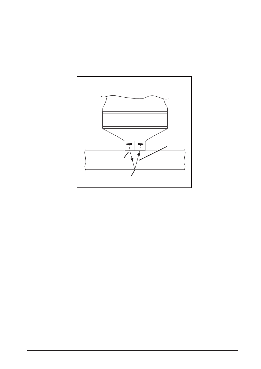
When using a flat dual probe, position the crosstalk barrier at a right
angle to the long axis of the part, as shown in Figure 6-1.
PROBE
CROSSTALK
BARRIER
LONG AXIS
OF TUBE
CONTACT
FÄCE
FIGURE 6-1—Crosstalk Barrier Orientation
PocketMIKE Operating Manual Page 23
Page 36

Page 24 PocketMIKE Operating Manual
Page 37

Troubleshooting
Guide
Should your instrument malfunction, refer to the guidelines that
correspond to the problem you’re experiencing:
PocketMIKE Operating Manual Page 25
Page 38

Page 26 PocketMIKE Operating Manual
Page 39

Warranty and Repair
8.1 Warranty
There are no warranties, expressed or implied by either distributor or
the manufacturer on new equipment except the manufacturer’s warranty against defects in material and workmanship set forth below:
GE Inspection Technologies warrants new instruments manufactured
by GE Inspection Technologies and delivered to the original retail
purchaser F.O.B. GE Inspection Technologies’s factory, to be free from
defects in material and workmanship under normal use and service, for
a period of two years from delivery of the instrument or unless otherwise stated by GE Inspection Technologies.
GE Inspection Technologies warrants new transducers manufactured
by GE Inspection Technologies and delivered to the original retail
purchaser F.O.B. GE Inspection Technologies’s factory, to be free from
defects in material and workmanship under normal use and service, for
ninety (90) days from the date of purchase.
These warranties are subject to the following limitations to which the
Buyer expressly agrees:
A. GE Inspection Technologies’s obligation under this warranty is
limited solely to repairing or replacing, at our option, and which,
upon examination by GE Inspection Technologies shall be found
to its reasonable satisfaction to have been thus defective. THIS
REMEDY IS EXPRESSLY SUBSTITUTED FOR ANY AND
ALL OTHER REMEDIES POSSIBLE UNDER THE UNIFORM
COMMERCIAL CODE, STATE, COMMON OR STATUTORY
LAW OR OTHERWISE.
PocketMIKE Operating Manual Page 27
Page 40

B. The provisions of this warranty SHALL NOT APPLY:
◆ To any instrument or transducer, which has been subject to
misuse, negligence or accident or which has been repaired
or altered outside GE Inspection Technologies’s factory in
any way so as to, in GE Inspection Technologies’s sole but
reasonable judgment affect its performance and reliability.
◆ To any instrument or transducer, which has been subjected
to an environment, chemistry or temperature that is not
compatible with the materials of construction.
◆ To any parts of an instrument or transducer, which, under
normal usage, would not or are not expected to last the
warranty period, i.e. “wear” items (i.e. batteries and
cables).
◆ To any instrument or transducer, which have not been
subject to proper care and maintenance.
◆ GE Inspection Technologies shall not be liable for any
damages, whether direct or indirect, economic, commercial,
incidental, or consequential, and whether arising from GE
Inspection Technologies’s negligence, breach of contract,
product liability, warranty or any other reason.
◆ To any instruments or transducer not manufactured by GE
Inspection Technologies. For equipment furnished, but not
manufactured by GE Inspection Technologies, GE Inspection Technologies assigns to the Buyer any warranty and/or
claim it may have against the manufacturer or supplier of
the equipment.
THIS WARRANTY IS EXPRESSLY IN LIEU OF ANY OTHER
WARRANTIES, EXPRESSED OR IMPLIED INCLUDING ANY
IMPLIED OR EXPRESSED WARRANTY OF MERCHANTABILITY, SUITABILITY OR FITNESS FOR A PARTICULAR PURPOSE
and GE Inspection Technologies neither assumes nor authorizes
another to assume any liability in connection with such equipment,
except as provided above.
Page 28 PocketMIKE Operating Manual
Page 41

8.2 Service
GE Inspection Technologies offers a complete Service Department for
repair and recertification of our products. You do not need a preauthorization number to send your GE Inspection Technologies unit
in for repair. Simply, provide the following information:
◆ Company Name
◆ Contact Name
◆ Phone Number
◆ Company Address
◆ Model Number
◆ Serial Number
◆ Accessories
◆ Description of problem or work required
◆ Any additional comments
and send it with your unit to:
GE Inspection Technologies, LLC
50 Industrial Park Road
Lewistown, PA 17044
U.S.A.
Phone: +1 (717) 242-0327
Fax.: +1 (717) 242-2606
or:
GE Inspection Technologies Systems GmbH
Robert-Bosch-Straße 3
D – 50354 Hürth
Germany
Phone: +49 (0) 2233 601111
Fax.: +49 (0) 2233 601402
PocketMIKE Operating Manual Page 29
Page 42

When shipping your unit, please take care to protect it from transit
damage. Static sensitive parts must be packaged in anti-static bags,
foam, or tubes. All products should be sent back in their original carry
cases, or wrapped in bubble wrap or other available packaging material.
GE Inspection Technologies warrants all repairs for a full 90 days.
Page 30 PocketMIKE Operating Manual
Page 43

Appendix
)evaWlanidutignoL(slairetaMsuoiraVniseiticoleVdnuoSlacipyT
rePsehcnI
dnocesorciM
munimulA0052.0036nolyN0001.0052
ssarB0071.0034cilonehP0650.0041
muimdaC0011.0082munitalP0061.0014
norItsaC0081.0064salgixelP0011.0082
reppoC0081.0064enelyhteyloP0070.0081
niseRyxopE0011.0082enerytsyloP0390.0042
)nworC(ssalG0022.0065enahteruyloP0070.0081
)wodniW(ssalG0072.0086nialecroP0022.0065
dloG0031.0033)lytuB(rebbuR0370.0091
lenocnI0022.0065).cluV(rebbuR0090.0032
daeL0580.0022revliS0041.0063
muisengaM0032.0085leetS0032.0085
esenagnaM0081.0064niT0031.0033
munedbyloM0052.0036muinatiT0042.0016
lenoM0012.0035netsgnuT0012.0035
enerpoeN0360.0061cniZ0061.0014
lekciN0022.00652yolacriZ0091.0074
Typical values for the sound velocity of many common materials.
Because processing, exact material composition, and temperature
affect velocity, these values may not precisely match the velocity
in the material being tested.
NOTE: This information is provided for the convenience of the user. GE
Inspection Technologies assumes no responsibility for inaccuracies. Actual
velocities depend on exact composition, temperature, and processing of each
material.
rePsreteM
dnoceS
rePsehcnI
dnocesorciM
dnoceS
rePsreteM
PocketMIKE Operating Manual Page 31
Page 44

Page 32 PocketMIKE Operating Manual
Page 45

Index
A
Auto .......................................................................................................... 10
B
Backlight .................................................................................................. 10
Backlight Adjustment ............................................................................. 10
Batteries .................................................................................................... 1
Battery indicator ....................................................................................... 2
Brightness ............................................................................................... 10
C
CAL ............................................................................................................. 6
Calibration ............................................................................................... 11
Curved Surfaces ..................................................................................... 22
D
Display ....................................................................................................... 5
donE ........................................................................................................... 6
E
EC Declaration of Conformity ............................................................... 20
F
FAIL ............................................................................................................ 6
Features ................................................................................................... 19
Flaws in the Specimen ........................................................................... 22
PocketMIKE Operating Manual Page 33
Page 46

H
HOT warning ........................................................................................... 17
K
Keypad ....................................................................................................... 4
L
Lockout .................................................................................................... 15
M
Material Consistency .............................................................................. 21
P
Powering On the Instrument ................................................................... 2
Probe transducer .................................................................................... 14
R
Repair ....................................................................................................... 29
Resolution ............................................................................................... 13
Reverse the display ................................................................................ 13
S
SAFE ........................................................................................................ 15
Service ..................................................................................................... 29
Specifications ......................................................................................... 19
Surface ..................................................................................................... 22
T
Temperature ............................................................................................ 17
Thickness ................................................................................................ 17
Thickness calibration ............................................................................. 11
Troubleshooting ..................................................................................... 25
Page 34 PocketMIKE Operating Manual
Page 47

U
Units of measurement ............................................................................ 13
V
Velocity calibration ................................................................................. 12
W
Warranty .................................................................................................. 27
PocketMIKE Operating Manual Page 35
 Loading...