

Page 1

Krautkramer MIC 20
Technical Reference and Operating Manual
Ident No. 28 702
Page 2

This Issue 02, 04/2005 applies to the software version V 01.00
The version number of the software is displayed in the menu bar line on the screen
or in the menu Config – Info (ref. chapter 4.7).
Subject to change without notice.
0-2 Issue 02, 04/2005 Krautkramer MIC 20
Page 3

Contents
1 Introduction ....................................... 1-1
1.1 Safety information ................................... 1-2
Power supply ............................................. 1-2
Software .................................................... 1-3
1.2 About this manual ................................... 1-3
Important information ................................. 1-3
1.3 Layout and presentation in this manual . 1-4
Attention and note symbols ....................... 1-4
Listings ...................................................... 1-4
Operating steps ......................................... 1-4
1.4 Prerequisites for hardness testing .......... 1-5
Operator training ........................................ 1-5
Technical test requirements ....................... 1-6
Choice of the appropriate test equipment ... 1-6
1.5 Important information about hardness
testing using the Krautkramer MIC 20 .... 1-7
Test material .............................................. 1-7
Test method ............................................... 1-7
Conversion of hardness values .................. 1-9
1.6 The Krautkramer MIC 20 ......................... 1-10
Special features of the MIC 20.................. 1-11
Large variety of application possibilities ....1-12
2 Standard package and accessories 2-1
2.1 Standard package .................................... 2-3
2.2 Required accessories .............................. 2-5
2.3 Recommended accessories
(general) .................................................... 2-7
2.4 Recommended accessories
(UCI method) ............................................ 2-8
2.5 Recommended accessories
(rebound method) ...................................2-11
2.6 Spare parts requirements
(UCI method) ...........................................2-12
2.7 Spare parts requirements
(rebound method) ...................................2-13
Krautkramer MIC 20 Issue 02, 04/2005 0-1
Page 4

ContentsContents
3 Initial start-up ..................................... 3-1
3.1 Power supply ........................................... 3-2
Operation using the power supply unit ........ 3-2
Operation using the battery pack
MIC 20-BAT ............................................... 3-3
3.2 Connecting a probe or
an impact device ...................................... 3-4
Connecting a UCI probe ............................. 3-5
Connecting an impact device ..................... 3-6
Disconnecting the connecting cable ........... 3-7
Exchanging the test attachment ................ 3-8
3.3 Turning on/off .......................................... 3-8
Turning on .................................................. 3-8
Turning off .................................................. 3-8
Emergency-stop ......................................... 3-9
Cold start ................................................... 3-9
4 Operation ........................................... 4-1
4.1 Fundamental principles of operation ..... 4-2
Operator’s controls and displays ................ 4-3
Display screen ........................................... 4-3
User interface ............................................ 4-4
Virtual keyboard......................................... 4-5
Operation using the keypad or
touch screen .............................................. 4-6
Installing the instrument ............................. 4-6
4.2 Probe and impact device ......................... 4-7
Guiding the probe ....................................... 4-7
Operating the impact device ...................... 4-8
4.3 Hardness testing .....................................4-10
Starting and closing a test series .............. 4-10
Viewing and evaluating test results ...........4-11
Conversion into other hardness scales ...... 4-14
4.4 Calibration ...............................................4-15
Carrying out the calibration ....................... 4-16
Saving calibration data ..............................4-18
0-2 Issue 02, 04/2005 Krautkramer MIC 20
Page 5

Contents
Deleting calibration data ............................4-19
Restoring the standard calibration ............. 4-20
4.5 Saving the test data ................................4-21
Saving files ............................................... 4-22
Deleting files or directories ........................4-22
Opening and closing directories ................4-23
Creating new directories ............................4-23
Opening files .............................................4-24
Editing saved files .................................... 4-24
File management using instrument keys ...4-25
4.6 Printing test reports ................................ 4-25
Prerequisites for printing ...........................4-26
Selecting and printing a test series ........... 4-27
4.7 Instrument configuration ........................4-30
Evaluation parameters ..............................4-30
System settings........................................ 4-35
System information ...................................4-39
4.8 Saving and loading
instrument parameters ...........................4-41
Saving instrument parameters .................. 4-41
Loading and deleting
instrument parameters ..............................4-41
4.9 Functional tests ......................................4-42
Functional test for UCI method .................4-42
Functional test for rebound method ........... 4-43
4.10 Calibrating the touch screen ..................4-44
4.11 Troubleshooting ......................................4-45
Error messages ........................................ 4-45
Errors ........................................................ 4-45
5 Care and maintenance ...................... 5-1
5.1 Care .......................................................... 5-2
Care of instrument ..................................... 5-2
Care of batteries ........................................ 5-2
Charging the batteries ................................ 5-3
Krautkramer MIC 20 Issue 02, 04/2005 0-3
Page 6

Contents
5.2 Maintenance ............................................. 5-4
Cleaning the probe ..................................... 5-4
Cleaning the impact device ........................ 5-4
6 Interfaces and data transfer.............. 6-1
6.1 Interfaces .................................................. 6-2
Serial interface RS232 ............................... 6-3
Ethernet interface ...................................... 6-3
6.2 Data transfer to a printer .......................... 6-4
Requirements for printing ........................... 6-4
6.3 Data transfer to a computer ..................... 6-5
7 Hardness testing method ................. 7-1
7.1 The UCI method ....................................... 7-2
The treatment of test material .................... 7-3
7.2 The rebound method ............................... 7-5
The treatment of test material .................... 7-6
7.3 Conversion of hardness values ............... 7-8
7.4 Information on the
statistical evaluation ............................... 7-12
Statistical average .................................... 7-12
Relative range of spread ...........................7-13
Relative standard deviation ....................... 7-13
Calculation of process capability ...............7-13
8 Specifications .................................... 8-1
Basic instrument ........................................ 8-2
Connections and interfaces ........................ 8-2
Power supply and operating time ................ 8-3
Ambient conditions .................................... 8-3
Evaluation .................................................. 8-4
9 Annex ................................................. 9-1
9.1 EC Declaration of Conformity ................. 9-2
9.2 Manufacturer/Service addresses ............. 9-2
10 Index ................................................. 10-1
0-4 Issue 02, 04/2005 Krautkramer MIC 20
Page 7

Introduction 1
Krautkramer MIC 20 Issue 02, 04/2005 1-1
Page 8

IntroductionIntroduction Safety information
1.1 Safety information
The Krautkramer MIC 20 is designed and tested according to DIN EN 61 010 Part 1, March 1994, “Safety
requirements for electric measuring, control, and laboratory devices”, and was technically in a perfectly safe
and faultless condition when leaving the manufacturing
works.
In order to maintain this condition and to ensure a safe
operation, it is absolutely necessary that you read the
following safety information before putting the instrument into operation.
A Attention:
The Krautkramer MIC 20 is an instrument meant for
materials testing. Any use in medical or other applications is not allowed!
The instrument may only be used in industrial environments.
Power supply
Battery pack and power supply unit
The Krautkramer MIC 20 can be operated using the
battery pack MIC 20-BAT, or a power supply unit. You
can charge the battery pack MIC 20-BAT in the instrument itself while the instrument is supplied with power
via the power supply unit and turned off. As soon as
you turn the instrument on, the power supply to the
battery compartment is interrupted.
NiCd or NiMH single cells
The operation using NiCd or NiMH single cells is likewise possible but is not recommended because of the
clearly reduced operating time.
A Attention:
You cannot charge NiCd or NiMH single cells in the
instrument itself but only by means of an external battery charger approved for this purpose.
If you are only using the power supply unit for a longer
period of time, you should remove the batteries from
the instrument.
1-2 Issue 02, 04/2005 Krautkramer MIC 20
Page 9

IntroductionIntroductionSafety information
H Note:
Alkaline cells are not suitable due to their high internal
impedance.
Software
According to the current state of the art, software is
never completely free from errors or defects.
For this reason, before using any software-controlled
test equipment, it should be ensured that the required
functions operate perfectly in the intended combination.
If you have any questions regarding the use of the instrument, please contact your nearest GE Inspection
Technologies representative.
1.2 About this manual
This manual describes the operation of the hardness
tester Krautkramer MIC 20.
Please read carefully through this manual in order to be
able to operate all functions of your instrument quickly
and reliably. You’ll be able to use the complete range of
instrument functions and, at the same time, to avoid
faults and operating errors which may lead to incorrect
test results.
Important information
Even if you might be familiar with hardness testing
methods, please always observe the information in
chapters 1.4 and 1.5. In chapter 1.4, you will find important limitations and prerequisites for hardness testing in
general (training, knowledge of the specific technical
test requirements and limits of testing, choice of the
appropriate test device).
In chapter 1.5, you will find concrete information about
hardness testing using the MIC 20 that you always have
to follow in order to ensure correct test results.
Krautkramer MIC 20 Issue 02, 04/2005 1-3
Page 10

IntroductionIntroduction Layout and presentation in this manual
1.3 Layout and presentation in
this manual
To make it easier for you to use the manual, the operating steps, notes, etc. are always presented in the same
way. This will help you find individual pieces of information quickly.
Attention and note symbols
A Attention:
You will find the Attention symbol in the case of any
peculiarities or special aspects in the operation which
could affect the correctness of the results.
H Note:
At Note, you will find e.g. references to other chapters
or special recommendations for a function.
Listings
Listings are presented in the following form:
❚ Variant A
❚ Variant B
❚ ...
Operating steps
Operating steps appear as shown in the following example:
– Place the handheld probe vertically to the surface to
be tested.
– Hold the probe tight with one hand so that the foot
stays perpendicular to the surface during the measurement.
1-4 Issue 02, 04/2005 Krautkramer MIC 20
Page 11

IntroductionIntroductionPrerequisites for hardness testing
1.4 Prerequisites for hardness
testing
In this operating manual you will find all essential information on how to operate the Krautkramer MIC 20. In
addition, there are a number of factors which affect the
test results. As a description of these factors would go
beyond the scope of an operating manual, only the
three most important conditions are therefore described
here:
❚ operator training
❚ knowledge of special technical test requirements and
limits
❚ choice of the appropriate test equipment
A Attention:
Lack of knowledge of the above-mentioned subjects
may lead to incorrect test results with unforeseeable
consequences.
GE Inspection Technologies organizes training courses
in the field of hardness testing. You will receive information on the scheduled dates on request.
Operator training
The reliable and safe operation of a hardness testing
device requires a proper training in materials testing.
A proper training comprises for example adequate
knowledge of:
❚ hardness testing on metallic materials
❚ effects due to material properties, especially due to
the microstructure, on hardness testing and on the
corresponding choice of the appropriate hardness
tester
❚ problems relating to the comparability of different
hardness values, such as Vickers, Rockwell, and
Brinell
❚ effects due to surface finish on the hardness value
❚ effects of the test load on the determined hardness
value
Krautkramer MIC 20 Issue 02, 04/2005 1-5
Page 12

IntroductionIntroduction Prerequisites for hardness testing
Technical test requirements
Every hardness test is subject to specific technical test
requirements. The most important ones are:
❚ definition of the scope of testing
❚ choice of the appropriate test method
❚ consideration of material properties
❚ determination of limits for evaluation
Choice of the appropriate test equipment
It is the task of those responsible for the test to fully
inform the operator about the technical test requirements. Moreover, a clear and thorough interpretation of
the corresponding test specifications is absolutely necessary.
Information about test methods and test specifications
may be obtained, for example, from various institutions,
industrial companies, and authorities.
1-6 Issue 02, 04/2005 Krautkramer MIC 20
Page 13

IntroductionIntroductionImportant information about hardness testing using the Krautkramer MIC 20
1.5 Important information about
hardness testing using the
Krautkramer MIC 20
Please find in the following a summary of the most
important technical test requirements that you always
have to observe in order to obtain reliable and reproducible test results.
A Attention:
Do not carry out the hardness test twice at the same
test position, otherwise measuring errors may occur
due to the hardness increase of the surface. The distance between the test positions should be at least
3 mm.
Krautkramer MIC 20 Issue 02, 04/2005 1-7
Test material
The surfaces must be free from any impurities (oil,
dust, etc.) and rust. The peak-to-valley height should
not exceed approx. 30 % of the penetration depth.
Rough surfaces lead to a higher variation range of the
single readings. If necessary, polish rougher surfaces,
for example using our grinding set MIC 1060 (ref. chapter 2).
Test method
The MIC 20 supports both quasi-static hardness testing
according to the UCI method and dynamic hardness
testing according to the rebound method.
All Krautkramer UCI probes and the rebound impact
devices D, G, and E are supported in these processes.
The UCI method
The UCI method is a comparative method (contribution
of the Young’s modulus to the measurement) with a
very high reproducibility of measurements. The UCI
method does not replace the classical Vickers hardness testing method but constitutes a fast and reliable
addition to it.
Page 14

IntroductionIntroduction Important information about hardness testing
The direct comparison with the results of the standardized Vickers measurement according to the material
samples is therefore indispensable for the assessment
of the measuring accuracy of the UCI method. This
means:
The test forces (probes) must match the surface quality
of the material:
❚ Smooth, homogeneous surfaces require low test
forces.
❚ Rougher, coarse-grained surfaces require as high
test forces as possible.
A Attention:
It is absolutely necessary that you calibrate your
MIC 20 to the material to be tested.
The calibration is required only once for this since you
can save calibrations and recall them again as required
without any problem (ref. chapter 4.4).
The calibration for low-alloy or unalloyed steel is already
predefined in the instrument. You should check them
from time to time (ref. chapter 4.9 Functional tests).
Please also read the notes on the UCI method in chapter 7.
The Rebound method
The rebound method is a dynamic method with a very
high reproducibility of measurements. The rebound
method does not replace the classical Brinell hardness
testing method or other standardized methods but constitutes a fast and reliable addition to them.
The still existing energy of an impact body after the
rebound from the material surface is measured. It
should be kept in mind in this regard that the loss of
energy suffered in this process also depends on the
mechanical properties of the material, i.e. mainly on its
Young’s modulus or modulus of elasticity.
The direct comparison with the results of the standardized Vickers measurement according to the material
samples is therefore indispensable for the assessment
of the measuring accuracy of the method. This means:
1-8 Issue 02, 04/2005 Krautkramer MIC 20
Page 15

IntroductionIntroductionImportant information about hardness testing
A Attention:
It is absolutely necessary that you set your MIC 20 to
the suitable material group before carrying out the test
and that you additionally calibrate it if necessary.
The calibration is necessary only once in this process
since you can save the calibrations and recall them
again as required without any problem (ref. chapter 4.4).
The material group for low-alloy or unalloyed steel is
predefined in the instrument as a default setting.
You should check this from time to time (ref. chapter
4.9 Functional tests).
Test objects having a mass of at least 5 kg can be
tested without any additional supports; more leightweight objects require a support to which they have to
be rigidly coupled. You should use large metal supports
that do not give way for this purpose.
The test objects should have a minimum wall thickness
of 20 mm. We recommend the UCI method, or the use
of a suitable UCI probe in combination with the MIC 20
for test objects having smaller wall thicknesses.
A Attention:
Should the test objects give way or spring, the result
may be measuring errors!
Please read also chapter 7 on the rebound method.
Conversion of hardness values
The conversion of hardness values into other hardness
scales is only possibly with restrictions.
Hardness values determined according to different
methods cannot be converted into each other by
means of generally applicable relations. The restrictions
regarding the conversion, stated in the DIN 50 150,
ASTM E140 specifications, must therefore always be
taken into account!
The indentation behavior of the material is determined
by its stress-strain behavior. Shape and material of the
indenter, the size of indentation, and consequently the
measured area vary, depending on the test method
used.
The conversion of hardness values both into one another and into tensile strength values can be inaccurate
Krautkramer MIC 20 Issue 02, 04/2005 1-9
Page 16

Introduction Important information about hardness testing
or unacceptable depending on the material, treatment
condition, and surface quality.
A Attention:
Any illegal or unacceptable conversions may lead
to serious errors in the interpretation of test results.
1.6 The Krautkramer MIC 20
The Krautkramer MIC 20 is a mobile and easy-to-use
hardness tester which can be equally used for tests
according to the UCI method and for tests according to
the rebound method.
After connecting the probe, the instrument is automatically set to the corresponding test method; tests can be
carried out quickly and without any problem.
The fact that both methods are supported leads to a
large variety of application possibilities with only one
single instrument. Additional probes extend the range of
applications if required.
The operation of the Krautkramer MIC 20 (calibration,
setup, evaluation, data memory) is carried out by
means of the graphic user interface presented on the
display and adapted to the known Windows standard.
The mouse is replaced by the touch screen for this
purpose.
As an alternative, conventional buttons are available for
most operating functions.
1-10 Issue 02, 04/2005 Krautkramer MIC 20
Page 17
IntroductionThe Krautkramer MIC 20
Special features of the MIC 20
❚ Measurements on castings and forgings, hardened
surfaces and welds
❚ Automatic adaptation of the test method and of the
test parameters to the connected probe
❚ Color LCD 5.7" for displays and operating functions
(TFT or CSTN)
❚ Support of all Krautkramer UCI probes
❚ Support of the Krautkramer rebound
impact devices D, G, and E
❚ Non-directional measurement (patented signal
processing with the rebound method)
❚ Storage of measurement data and clear representa-
tion of measurement series as a diagram and histogram
❚ Simple and fast calibration, saving and recalling of
calibration data at the press of a button
❚ Output of measurement data directly to a printer or
transfer to a computer
Krautkramer MIC 20 Issue 02, 04/2005 1-11
Page 18

Introduction The Krautkramer MIC 20
❚ Operation using the battery pack or power supply
unit
Large variety of application possibilities
You can use the Krautkramer MIC 20 to measure anywhere and in any direction; the direction must not be
set beforehand.
The MIC 20 is mainly suitable
❚ for measuring hardness of low-alloy or unalloyed
steels,
❚ for measuring hardness of high-alloy steels,
❚ for measuring hardness of nonferrous metals.
The MIC 20 is available in two versions:
❚ Basic version MIC 20 with color CSTN screen
❚ MIC 20 TFT with color TFT display screen
1-12 Issue 02, 04/2005 Krautkramer MIC 20
Page 19

Standard package and accessories 2
Krautkramer MIC 20 Issue 02, 04/2005 2-1
Page 20

Standard package and accessories Standard package
This chapter informs you about the standard package
and the accessories available for the Krautkramer
MIC 20.
It describes
❚ component parts of the product
❚ required and recommended accessories
❚ spare parts requirements
2-2 Issue 02, 04/2005 Krautkramer MIC 20
Page 21

2.1 Standard package
Product code Description Order no.
MIC 20 Portable Hardness Tester according to the quasi-static 35 468
Standard package and accessoriesStandard package
UCI principle and the dynamic Rebound principle.
Display of the hardness values in HV, HB, HRC,
HRB, N/mm
in HL and HS.
including:
Instrument MIC 20 35 493
Mains adapter 101 075
Transport case 101 554
Operating manual German 28 701
or
Operating manual English 28 702
2
and additional for the Rebound principle
Krautkramer MIC 20 Issue 02, 04/2005 2-3
Page 22

Standard package and accessories Standard package
Product code Description Order no.
MIC 20 TFT Portable Hardness Tester according to the quasi-static 35 479
UCI principle and the dynamic Rebound principle.
Display of the hardness values in HV, HB, HRC, HRB,
2
N/mm
and additional for the Rebound principle
in HL and HS.
including:
Instrument MIC 20 TFT 35 492
Mains adapter 101 075
Transport case 101 554
Operating manual German 28 701
or
Operating manual English 28 702
2-4 Issue 02, 04/2005 Krautkramer MIC 20
Page 23

2.2 Required accessories
Product code Description Order no.
MIC 201-A Handheld probe 10 N 34 104
MIC 205-A Handheld probe 50 N 34 105
MIC 2010-A Handheld probe 98 N 34 106
MIC 201-AL Extended handheld probe 10 N 34 392
MIC 205-AL Extended handheld probe 50 N 34 282
MIC 201-AS Short handheld probe 10 N 34 711
MIC 205-AS Short handheld probe 50 N 34 712
Standard package and accessoriesRequired accessories
Handheld Probes (UCI method)
(each probe complete with cable)
Krautkramer MIC 20 Issue 02, 04/2005 2-5
Page 24

Standard package and accessories Required accessories
Product code Description Order no.
Motorized Probes (UCI method)
(each probe complete with cable)
MIC 211-A Motor probe 8.6 N 34 381
MIC 2103-A Motor probe 3 N 34 382
MIC 2101-A Motor probe 1 N 35 577
Impact Devices (rebound method)
(each without connecting cable for impact device)
Dyna D Impact device with 3 mm tungsten-carbide 34 248
Dyna G Impact device with 5 mm tungsten-carbide 34 549
Dyna E Impact device with diamond-tipped body 34 588
Dyna 50 Connecting cable for impact device 34 329
2-6 Issue 02, 04/2005 Krautkramer MIC 20
Page 25

Recommended accessories (general)
2.3 Recommended accessories (general)
Product code Description Order no.
MIC 20-BAT NiMH accumulator pack, 4.5 Ah, internal charging 35 452
MIC 1060 Battery grinding set 34 380
MIC 300 Technical book on hardness testing (only in German) 28 837
Printer cable (serial/parallel) for connection to 101 761
Hewlett Packard Printers of the hpdeskjet 9xx series
UDAT UltraDAT data management program for transfer and 35 549
documentation of hardness measurement data
Data transfer cable from the instrument to a PC 101 785
ZG-F Couplant 54 558
Standard package and accessories
Krautkramer MIC 20 Issue 02, 04/2005 2-7
Page 26

Standard package and accessories
2.4 Recommended accessories (UCI method)
Product code Description Order no.
Guiding devices and test supports
MIC 270 Surface attachment for MIC 201-A, MIC 205-A, 32 084
MIC 2010-A
MIC 271 Prism adapter for MIC 201-A, MIC 205-A 32 993
MIC 220 Test specimen holder for MIC 2101-A, MIC 2103-A 30 766
and MIC 211-A
MIC 221 Universal test support with instrument holder 33 541
MIC 227 Test support for determination of hardness progression 35 264
MIC 222-A Precision test support 35 546
MIC 2221 Magnetic foot for support MIC 222-A 33 909
MIC 2220 Support block for flat, thin parts 33 651
Recommended accessories (UCI method)
MIC 225 Camshaft test stand 34 869
2-8 Issue 02, 04/2005 Krautkramer MIC 20
Page 27

Recommended accessories (UCI method)
Product code Description Order no.
MIC 100 Probe attachment set 29 929
MIC 100-1 Prism attachment 29 920
MIC 120 Magnetic probe shoe for curved surfaces 31 854
MIC 223 Quick test support with magnetic foot 34 020
MIC 25C Hardness Reference Plate 25 HRC 33 905
MIC 45C Hardness Reference Plate 45 HRC 33 906
MIC 65C Hardness Reference Plate 65 HRC 33 907
MIC 1V100 Hardness Reference Plate 150 HV10 34 279
MIC 2V010 Hardness Reference Plate 240 HV1 33 896
Standard package and accessories
Guiding devices for motor probes
Hardness reference plates with MPA certificate
MIC 2V050 Hardness Reference Plate 240 HV5 33 899
Krautkramer MIC 20 Issue 02, 04/2005 2-9
Page 28

Standard package and accessories
Product code Description Order no.
MIC 2V100 Hardness Reference Plate 240 HV10 33 902
MIC 5V010 Hardness Reference Plate 540 HV1 33 897
MIC 5V050 Hardness Reference Plate 540 HV5 33 900
MIC 5V100 Hardness Reference Plate 540 HV10 33 903
MIC 8V010 Hardness Reference Plate 840 HV1 33 898
MIC 8V050 Hardness Reference Plate 840 HV5 33 901
MIC 8V100 Hardness Reference Plate 840 HV10 33 904
Recommended accessories (UCI method)
2-10 Issue 02, 04/2005 Krautkramer MIC 20
Page 29

Recommended accessories (rebound method)
Standard package and accessories
2.5 Recommended accessories (rebound method)
Product code Description Order no.
Hardness reference blocks (rebound method)
MIC D62 Hardness reference block 620 HV100 34 393
MIC D62MPA Hardness reference block 620 HV100, 34 573
certified by MPA, Germany
MIC G38 Hardness reference block 380 HV100 34 631
MIC G38MPA Hardness reference block 380 HV100, 34 657
certified by MPA, Germany
Test attachments for Dyna D and E (rebound method)
Dyna 41 Set (5 pcs.) of test attachments for cylindrical and 34 536
hollow-cylindrical surfaces
Dyna 42 Set (5 pcs.) of test attachments for spherical and 34 539
hollow-spherical surfaces
Krautkramer MIC 20 Issue 02, 04/2005 2-11
Page 30

Standard package and accessories
2.6 Spare parts requirements (UCI method)
Product code Description Order no.
MIC 1050 Probe cable for handheld probes 34 071
MIC 1051 Probe cable for motor probes 34 378
MIC 1052 Probe cable for shortened handheld probes for 34 713
MIC 201-AS and MIC 205-AS
Ball headed probe grip 33 854
Spare parts requirements (UCI method)
2-12 Issue 02, 04/2005 Krautkramer MIC 20
Page 31

Spare parts requirements (rebound method)
Standard package and accessories
2.7 Spare parts requirements (rebound method)
Product code Description Order no.
Impact body D, new 34 443
Impact body G, new 34 596
Impact body E, new 34 593
Impact body D, replacement in exchange by 34 572
Krautkramer Service Department
Impact body G, replacement in exchange by 35 265
Krautkramer Service Department
Dyna 50 Connecting cable for impact device 34 329
Cleaning brush for Dyna D or Dyna E 34 420
Cleaning brush for Dyna G 34 618
Standard test attachment for impact device D or E 34 312
Test attachment for impact devices D or E, 34 656
Ø = 13.5 mm
Krautkramer MIC 20 Issue 02, 04/2005 2-13
Page 32

Standard package and accessories
Product code Description Order no.
Spare parts requirements (Rebound method)
Standard test attachment for impact device G 34 569
Test attachment for impact device G, 34 634
diameter = 50 mm
Replacement grinder for battery grinding set MIC 1060 18 115
2-14 Issue 02, 04/2005 Krautkramer MIC 20
Page 33

Initial start-up 3
Krautkramer MIC 20 Issue 02, 04/2005 3-1
Page 34

Initial start-up Power supply
3.1 Power supply
You can operate the Krautkramer MIC 20 either with the
battery pack MIC 20-BAT or with the power supply unit.
The operation with the power supply unit is possible
even if the battery pack MIC 20-BAT is in the instrument. The power supply to the battery compartment is
then automatically interrupted.
Operation using the power supply unit
The Krautkramer MIC 20 is supplied either with a desktop power supply unit or with a plug-in power supply
unit. The power supply unit is automatically set to any
a.c. voltage between 100 and 240 V (nominal voltage).
Operation using the desktop power supply unit
The desktop power supply unit is provided with a cable
equipped with a Euro plug connector and inlet connector for non-heating appliances.
Plug the cable’s inlet connector for non-heating appliances in the socket for non-heating appliances of the
power supply unit.
Operation using the plug-in power supply unit
The plug-in power supply unit is delivered with two different socket-outlet adapters – for Euro and U.S. standard. If the adapter plug on your power supply unit does
not correspond to your socket-outlet standard, you can
exchange it.
Just pull off the attached adapter, and replace it with
the required one.
H Note:
You should exchange the socket-outlet adapter only
once; the plug-in power supply unit is not meant for
frequent exchanges.
3-2 Issue 02, 04/2005 Krautkramer MIC 20
Page 35

Initial start-upPower supply
Connecting
Use the corresponding power supply unit to connect the
Krautkramer MIC 20 to a suitable mains socket-outlet.
The socket-contact for the power supply unit cable is
located at the back of the instrument.
Operation using the battery pack
MIC 20-BAT
You can operate the Krautkramer MIC 20 with the NiMH
battery pack MIC 20-BAT (ref. chapter 2).
The operation is likewise possible with 6 NiCd or NiMH
single C-cells each, however, it is not recommended
because of the clearly reduced operating time.
Inserting batteries
The battery compartment is located in the instrument
bottom.
– Move the fastener towards the lid center in order to
open the lid, and remove the lid.
– Insert the plug of the battery pack into the socket-
contact in the battery compartment until it snaps into
place. When inserting the battery pack, make sure
that no squeezing or kinking of the cables is possible.
– If you use single cells, insert the individual cells into
the battery compartment one by one. Follow the instructions regarding alignment and polarity in the
battery compartment.
– Place the lid back on, move the fastener back and
close the battery compartment so that the fastener
locks home perceptibly.
Krautkramer MIC 20 Issue 02, 04/2005 3-3
Page 36

Initial start-up Power supply
H Notes:
Remove the batteries from the instrument if you’re not
going to use it for a longer period of time!
Used or defective batteries are special waste and have
to be disposed of as provided by the law!
When using the battery pack MIC 20-BAT (unless NiMH
or NiCd single cells are used), the current status of the
battery is indicated on the display of the MIC 20 by an
icon:
An alarm is output with low voltage. In such a case,
exchange the batteries at once. The Krautkramer
MIC 20 is automatically turned off if the voltage gets
too low in order to ensure a reliable mode of functioning.
You will find more details on the care and charging of
batteries in chapter 5.
3.2 Connecting a probe or an
impact device
You can connect probes for the quasi-static hardness
testing according to the UCI method as well as impact
devices for the dynamic hardness testing according to
the rebound method to the MIC 20.
Probes and impact devices are connected to the
MIC 20 via corresponding connecting cables. The connecting cables are equipped with a round plug for the
connection to the probe or to the impact device, and
with a square plug for the connection to the instrument.
H Note:
You should only change the probe or the impact device
when the MIC 20 is switched off.
3-4 Issue 02, 04/2005 Krautkramer MIC 20
Page 37

Connecting a UCI probe
– Align the round plug of the cable correctly with the
socket of the probe by means of the markings, and
push it carefully into the socket until it locks into
place.
– Plug the square plug of the connecting cable in the
socket at the back of the instrument.
– Check that both plugs fit tightly.
– Attach the probe handle to the probe if necessary.
– Screw on the conical test attachment for short-time
measurements using the UCI handheld probes
MIC 201-A, MIC 205-A, or MIC 2010-A. Use the cylindrical test attachment for measurements with defined dwell times.
– Switch the MIC 20 on. An icon in the top left corner
of the screen shows that a probe has been correctly
connected:
Initial start-upConnecting a probe or an impact device
Conical probe attachment for
short-time measurements
Cylindrical probe attachment for
measurements with a defined
dwell time
Krautkramer MIC 20 Issue 02, 04/2005 3-5
Page 38

Initial start-up Connecting a probe or an impact device
H Note:
If you want to carry out measurements with defined
dwell times, please use the support
MIC 222-A (support with precise probe guidance).
This will help you to avoid measuring inaccuracies to a
large degree.
In addition, other accessories are available to make the
measurements easier for you to carry out (ref.
chapter 2).
Connecting an impact device
The following impact devices are available for use in
combination with the MIC 20:
❚ Dyna D
Standard impact device for all materials that can be
tested
❚ Dyna G
Impact device for solid test objects, e.g. castings or
forgings
❚ Dyna E
Impact device for the hardness range over 650 HV
A Attention:
The impact device Dyna G must only be used up to a
hardness to be tested of max. 650 HB, otherwise the
impact body may be destroyed.
H Note:
A larger test attachment (diameter 50 mm) is available
for the impact device Dyna G for a more stable measurement on large, flat workpieces.
3-6 Issue 02, 04/2005 Krautkramer MIC 20
Page 39

Connecting a probe or an impact device
Initial start-up
For measurements on test objects having curved surfaces, you have special test attachments at your disposal in order to achieve a better positioning with the
impact devices Dyna D and Dyna E (ref. chapter 2).
– Align the round plug of the cable correctly with the
socket of the probe by means of the markings, and
push it carefully into the socket until it locks into
place.
– Plug the square plug of the connecting cable in the
socket at the back of the instrument.
– Check that both plugs fit tightly.
– Screw on the suitable test attachment for measure-
ments on curved surfaces if necessary.
– Switch the MIC 20 on. An icon in the top left corner
of the screen shows that a probe has been correctly
connected:
Disconnecting the connecting cable
The round plug is provided with a bayonet lock, the
square plug has two locking clips.
– Carefully pull the outer ring of the round plug on the
probe or on the impact device in order to release the
lock, and pull off the plug.
– Press the two lateral clips of the square plug on the
instrument in order to release the lock, and pull off
the plug.
Krautkramer MIC 20 Issue 02, 04/2005 3-7
Page 40

Initial start-up
Connecting a probe or an impact device
Exchanging the test attachment
You can use special test attachments for testing on
small parts and on uneven surfaces in order to achieve
a better positioning of the probe or of the impact device.
– Slowly unscrew the currently used test attachment
counter-clockwise by hand.
– Place the required test attachment on carefully.
Make sure that the threads are not damaged by tilting.
– Carefully screw on the test attachment clockwise
and by only using manual force all the way to the
limit stop.
3.3 Turning on/off
Turning on
– Briefly press the button o to turn the instrument on.
The operating system will start, and some information,
e.g. about the software, is briefly displayed on the
screen. When the instrument is ready, you will see the
graphic user interface.
Turning off
– Briefly press the button o to turn the instrument off.
A Attention:
You should always use the button
erly turn the instrument off. In the case of an interruption of the power supply (battery removal, unplugging of
power plug), the instrument is not turned off properly,
and data may be lost.
o in order to prop-
3-8 Issue 02, 04/2005 Krautkramer MIC 20
Page 41

Turning on/off
Emergency-stop
If the instrument no longer shows any reaction, you can
turn it off without saving the current data. Afterwards,
you can turn it back on as usual.
Initial start-up
– To turn off, keep the button
the screen is blanked, and the instrument is turned
off.
o pressed down until
Cold start
If the instrument no longer reacts and cannot be started
properly, you can reset the settings with a cold start.
A Attention:
In a cold start, the files LastMeasure.mes and last.set
are deleted so that the last measurement series and
the saved calibration data may be lost.
– To switch on the instrument, briefly press
the button
– As soon as the start screen (blue background) ap-
pears, press the button
Krautkramer MIC 20 Issue 02, 04/2005 3-9
o.
.
Page 42

3-10 Issue 02, 04/2005 Krautkramer MIC 20
Page 43

Operation 4
Krautkramer MIC 20 Issue 02, 04/2005 4-1
Page 44

Operation Fundamental principles of operation
4.1 Fundamental principles of operation
4-2 Issue 02, 04/2005 Krautkramer MIC 20
Page 45

OperationFundamental principles of operation
Operator’s controls and displays
1 Temperature sensor (no operating function)
2 Select keys to select the main menus
3 Touch-sensitive screen (touch screen), for direct
operation of the graphic interface
4 Key to turn on and off
5 Red LED,
is lit in the case of alarms and if the preset threshold
values for hardness measurements are exceeded
6 Green LED,
is lit with an active charging process,
flashes quickly with a finished charging process,
flashes slowly if the battery voltage or the temperature are out of tolerances
7 Arrow keys for navigation in the menus, and for acti-
vation of functions
8 Select keys for submenus and functions
Display screen
The Krautkramer MIC 20 is equipped with a touch
screen enabling a direct operation of the menus appearing on the screen.
The graphic user interface is adapted to the known
Windows standards. The operation by means of a
mouse (selecting and clicking) is in this case replaced
with direct touch on the screen. A mouse pointer is
therefore not necessary.
To select or to mark an element of the user interface,
just touch the corresponding point of the screen briefly
with your finger or with the pen provided for the instrument.
The pen is located in the holder at the instrument bottom.
A Attention:
Do not touch the touch screen with any hard or sharpedged objects (e.g. ball-point pen or screw driver). The
touch-sensitive surface may be severely damaged by
them.
Krautkramer MIC 20 Issue 02, 04/2005 4-3
Page 46

Operation Fundamental principles of operation
Do not apply any high pressure to the screen, the touch
screen needs only slight pressure to react.
User interface
The 3 main menus Data, Config, and Measure are dis-
played on the screen. The 3 main menus have different
user interfaces.
The buttons as well as the option and other boxes
shown on the user interface can be operated by directly
touching the touch screen, or by pressing the corresponding key next to the screen.
H Note:
The contents of the menu differ in some details, depending on the fact whether a probe or an impact device is connected to the MIC 20.
Main menu Measure Main menu Config
4-4 Issue 02, 04/2005 Krautkramer MIC 20
Main menu Data
Page 47

Virtual keyboard
A virtual keyboard is available for text and value inputs
and is automatically displayed if the corresponding
input fields are activated.
The virtual keyboard can also be turned on and off by
hand.
– Touch the button with the keyboard icon on it, next to
the battery icon. The virtual keyboard is displayed.
– Touch the broad bar above the displayed keys, keep
the pen pressed down, and move the keyboard with
the pen pressed down.
– Touch the button with the keyboard icon on it once
again. The virtual keyboard is turned off again.
OperationFundamental principles of operation
Krautkramer MIC 20 Issue 02, 04/2005 4-5
Page 48

Operation Fundamental principles of operation
Operation using the keypad or touch
screen
You can use either the keys arranged around the screen
to operate all menus and functions or, as an alternative,
directly the touch screen.
At the beginning, use both alternatives in order to test
the advantages of either one in practice.
In general, this manual only describes the direct operation by means of the touch screen. If the operation alternative using the keyboard presents a special advantage, it is additionally mentioned at that point.
The keys and menus or functions are arranged in such
a way that a clear assignment can always be seen.
Consequently, you’ll always have the following two alternatives:
– Touch the button of a function.
or
– Press the key next to (or below) the function.
Installing the instrument
The instrument has a prop-up lever stand at its bottom
enabling you to install the instrument at varying angles.
You should always ensure that you have a good view of
the screen in order to work as ergonomically as possible and to avoid overstraining yourself unnecessarily.
– Fold out the lever stand, and let it lock into the re-
quired position.
– Install the instrument in such a way that you have a
good and non-dazzling view of it.
4-6 Issue 02, 04/2005 Krautkramer MIC 20
Page 49

Probe and impact device
Operation
4.2 Probe and impact device
Guiding the probe
A Attention:
Make sure that the probe is connected before switching
the MIC 20 on so that the instrument is automatically
set to the UCI method.
Reliable measurement results can only be obtained if
you know how to handle the probe correctly and safely.
Please always observe the following rules:
❚ Avoid any rough placing of the probe on the test sur-
face in order not to damage the diamond.
❚ Do not move the probe under load on the test material.
❚ Pay attention to guiding the probe smoothly and
steadily using your both hands.
❚ Do not carry out measurements twice at the same
test position. The distance between the test positions
should be at least 3 mm.
H Note:
After placing the probe on the test surface, the measurement must be carried out within 3 seconds. Otherwise an error message will be given and you have to
start the process again.
– Select the main menu Measure.
– If necessary, remove the rubber protection cap from
the probe.
– Screw on the conical test attachment for short-time
measurements.
– Hold the probe with your both hands in order to have
the best possible control during guidance and during
impressing in the material surface.
– Place the probe vertically on the surface to be
tested. An icon at the top edge on the screen shows
the contact of the probe with the test material:
Krautkramer MIC 20 Issue 02, 04/2005 4-7
Page 50

Operation
Probe and impact device
– Hold the probe with one hand tightly enough so that it
doesn’t tilt and press it evenly and steadily against
the surface with the other hand.
– Increase the pressure steadily until the probe’s spe-
cific load is attained and you hear an acoustic signal.
The measured hardness value is displayed on the
screen.
– Lift off the probe and place it again at another posi-
tion in order to carry out other measurements.
H Note:
If you have pressed the probe down up to the limit stop
without any measured value being determined (no
acoustic signal), check the following possible causes:
❚ The load was applied too fast. Try again by increas-
ing the pressure more slowly.
❚ The instrument has not been calibrated correctly
beforehand.
❚ The hardness of the surface tested is beyond the
probe’s range of measurement.
Operating the impact device
A Attention:
Make sure that the impact device is connected before
switching the MIC 20 on so that the instrument is automatically set to the rebound method.
The impact device Dyna G must only be used up to a
hardness to be tested of max. 650 HB, otherwise the
impact device may be destroyed.
Reliable measurement results are only obtained if you
know how to handle the impact device correctly and
safely.
You should always observe the following rules:
❚ Always use an impact device suitable for the appli-
cation and equipped with the appropriate test attachment.
❚ Do not carry out measurements twice at the same
test position. The distance between the test positions
should be at least 3 mm.
4-8 Issue 02, 04/2005 Krautkramer MIC 20
Page 51

Probe and impact device
Operation
❚ Never load the impact device at the actual test posi-
tion (surface hardening) but somewhere else (e.g. at
a table or another position of the test object).
❚ Keep the following in mind when using the test at-
tachments Dyna 41 and Dyna 42 so that the impact
device is correctly loaded: do not tension the impact
device by pushing the load tube through „in the air”
but by e.g. pressing one finger against it or by placing the impact device on the test surface. After that,
put the impact device at the actual test position.
– Select the main menu Measure.
– Tension the impact device by pushing the load tube
all the way through to the limit stop and by moving it
slowly back to the initial position.
– Place the impact device vertically on the test sur-
face and press it slightly against it with one hand so
that it doesn’t tilt.
– Use the index finger of the other hand to press the
release button. An acoustic signal is heard if the
measurement was successful.
– Lift off the impact device. The measured hardness
value is displayed on the screen.
Release button
Load tube
Test attachment
Krautkramer MIC 20 Issue 02, 04/2005 4-9
Page 52

Operation
Hardness testing
4.3 Hardness testing
A Attention:
In order to obtain correct measurement results, it is
absolutely necessary to calibrate the MIC 20 to the test
object’s material before starting any measurements.
You have to repeat the calibration process for every
new material. You must likewise repeat the calibration
whenever you change the test method.
The calibration is described in detail in the following
chapter 4.4. As you have to carry out measurements
for the calibration, please read the present chapter first
in order to learn how to edit measurement series and
view measurement results.
H Note:
When the MIC 20 is switched off, the instrument settings (including calibration) of the last measurement are
saved and will again be available unchanged when the
instrument is switched on the next time. Check the
current settings prior to every measurement series.
Starting and closing a test series
If you use test series, you can end a test series any
time, and start a new one. The statistical evaluations
always refer to the currently active test series.
– Select the main menu Measure.
– Select one of the functions Curve, Histogr. or Sta-
tistics at the bottom edge of the display.
– Touch the button New in order to start a new test
series.
– Touch the button Delete in order to delete a test se-
ries that has possibly already been recorded. The
readings are deleted, and a new test series is
started.
You can now start measuring.
The processes of saving and editing test results are
described later in this manual (ref. chapter 4.5).
4-10 Issue 02, 04/2005 Krautkramer MIC 20
Page 53

Hardness testing
Operation
Viewing and evaluating test results
Various information is shown to you in the main menu
Measure, depending on the selected view, e.g. the current hardness value, the list of previous measured values, or the statistical distribution of measured values.
Details depend on the current method of measurement.
You can choose between three display view modes for
measurements:
You have a choice between three display modes for the
measurements:
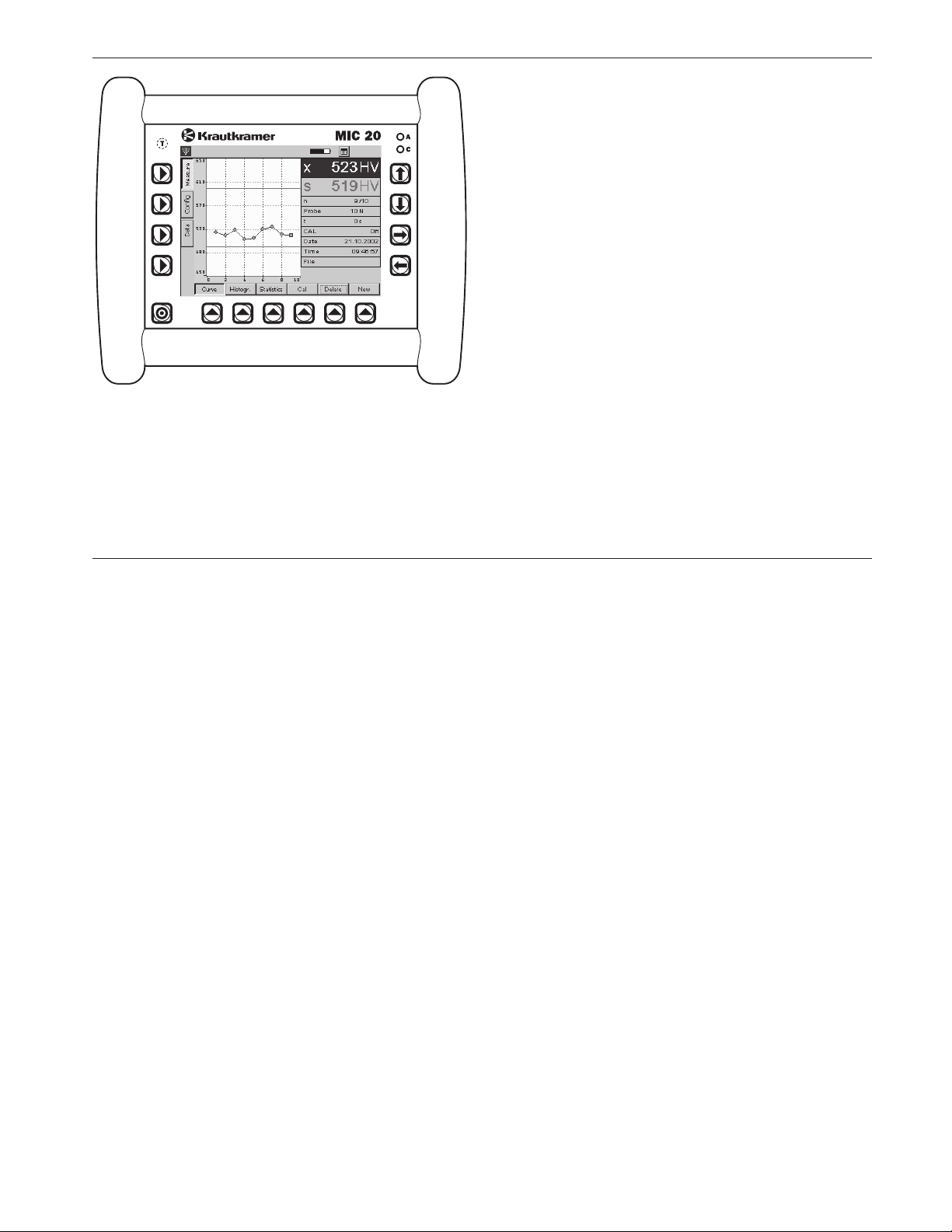
❚ Curve
❚ Histogram
❚ Statistics
H Note:
The different display modes have no effect on the process of measurement.
The current reading (s), the current statistical average
(x), and the number of measurements (n) can be seen
in all four display modes.
– Select the main menu Measure.
– Select one of the functions at the bottom edge of the
display in order to see the corresponding display
mode.
Curve function
The measured hardness values are displayed as a
curve in a diagram. The shape of the curve helps you
with the evaluation of the test results.
Krautkramer MIC 20 Issue 02, 04/2005 4-11
Page 54

Operation
Hardness testing
The horizontal green lines show the tolerance limit settings. Readings within the tolerance range are displayed
in green, readings outside in red.
In addition to the diagram, other information is displayed for every measured value:
Probe Test load of the probe or
type of the impact device
t Dwell time (only with UCI method)
CAL Calibration number (Off = standard material)
Mat. Selected material group
(only with rebound method)
Date Date of measurement
Time Hour of time of measurement
File File name when editing an already saved
measurement series
You can delete individual test results.
– Touch the required reading to select it.
– Touch the button Delete. The selected reading is
immediately deleted.
H Note:
You can also select the reading by means of the arrow
keys to the right of the screen display.
4-12 Issue 02, 04/2005 Krautkramer MIC 20
Page 55

Hardness testing
Operation
Histogr. function
The histogram shows the statistical distribution of the
readings of the current test series.
Besides the graphics, additional statistical single values are displayed (ref. chapter 7.4):
S Standard deviation (absolute and percentage)
R Range of spread (absolute and percentage)
cp Process capability index
cpk Critical process capability index
Statistics function
The Statistics function shows the test results of a test
series in tabular form.
Krautkramer MIC 20 Issue 02, 04/2005 4-13
Page 56

Operation
Hardness testing
Besides the table, additional statistical single values
are displayed (ref. chapter 7.4):
S Standard deviation (absolute and percentage)
R Range of spread (absolute and percentage)
Min Minimum value
Max Maximum value
Test results situated within the set tolerance limits are
shown in blue characters, test results outside the tolerance are shown in red characters.
You can delete individual test results.
– Touch the required reading in order to select it.
– Touch the button Delete. The selected reading is
immediately deleted.
H Note:
You can also select the reading by means of the arrow
keys to the right of the screen.
Conversion into other hardness scales
You can directly convert the test results obtained into
other hardness scales.
A Attention:
Any illegal or unacceptable conversions may lead
to serious errors in the interpretation of test results.
You should always pay attention to the information
given in chapter 7.3 of this manual regarding the conversion of test results.
4-14 Issue 02, 04/2005 Krautkramer MIC 20
Page 57

Hardness testing
Operation
H Note:
The list of hardness scale options is not automatically
adapted to the test method or the impact device used.
If your choice is not accepted by the instrument, the
selected conversion is not possible. A corresponding
note is displayed on the screen.
– Touch the abbreviation of the current hardness scale
(e.g. HV) at the item Average (x) in the right-hand
screen section. An options menu is displayed.
– Touch the abbreviation of the required hardness
scale (e.g. HB). All values of the current
measurement series are displayed in the new scale.
4.4 Calibration
A Attention:
In order to obtain correct measurement results, it is
absolutely necessary to calibrate the MIC 20 to the test
object’s material before starting any measurements.
You have to repeat the calibration for every new material. When changing the test method, you have to likewise repeat the calibration procedure.
H Note:
If you want to measure on low-alloy or unalloyed steels,
there’s no need to set the instrument because this material group is the default setting of the MIC 20.
When switching the MIC 20 off, the instrument settings
(including calibration) of the last measurement are
saved and will be available again unchanged when the
instrument is switched on the next time. Check the
current settings prior to every measurement series.
Krautkramer MIC 20 Issue 02, 04/2005 4-15
Page 58

Operation
Calibration
Carrying out the calibration
The calibration procedure is basically identical for the
UCI method and for the rebound method.
You only have to start by selecting one of the material
groups stored in the instrument as an additional action
with the rebound method.
You need a reference block made of the same material
with known hardness for the calibration. During the calibration, you determine the calibration number that you
need in other measurements on this material.
The calibration number is an auxiliary value that simplifies the subsequent change of the calibration setting.
The calibration number has no physical reference whatsoever and consequently no name either.
As you can save the calibration in the MIC 20, you only
have to carry out the calibration once for a certain material.
Only with calibration for rebound method:
If you want to carry out measurements on high-alloy
steels or on other materials, e.g. nonferrous metals,
you have to set the MIC 20 to the required material. To
do this, you start by choosing the suitable material
from the 9 existing ones. For precision measurements,
you have to carry out a calibration afterwards for the
adjustment.
– Touch the button Cal. The calibration menu is dis-
played.
– Touch the list box Material group. The list of the
stored material groups appears.
4-16 Issue 02, 04/2005 Krautkramer MIC 20
Page 59

Calibration
Operation
– Touch the material group corresponding to the test
object. The list is closed again.
– Finally, touch the button OK to close the menu.
Notes on the material groups:
The MIC 20 makes 9 material groups available. However, not all material groups are suitable for the different
impact devices. Please observe the assignment in the
table below:
Material group Impact device
ST - steel and cast steel D E G
AST - tool steel D E
SST - stainless steel D
GCI - gray cast iron D G
NCI - nodular cast iron D G
AL - aluminum cast alloys D
BRZ - bronze D
CU - wrought copper alloys D
Calibration for UCI and rebound method:
– Carry out a series of measurements consisting of
about 5 single measurements on your reference
block.
– Touch the button Cal. The calibration menu is dis-
played.
The current statistical average of your measurements
is displayed at the item Real value. However, this value
does not correspond to the known, real hardness value
because you have not yet calibrated the instrument.
You will now have to adapt the displayed value to the
known hardness value of your reference block.
– Double-touch the item Target value in order to mark
the value displayed there.
BRS - brass D
Krautkramer MIC 20 Issue 02, 04/2005 4-17
Page 60

Operation
Calibration
– Touch the button Select at the bottom edge of the
screen. The virtual keyboard is displayed, and you
can input the required target value.
– Key in the value by touching the corresponding char-
acters on the keyboard.
– Finally, touch the displayed Return (ENTER) key. The
keyboard disappears again.
According to the input hardness value, the MIC 20
will automatically determine the calibration number
which is immediately displayed at the item Cal.
Number.
Having calibrated the MIC 20, you can carry out
hardness tests as described above.
– Touch the button OK in order to close the calibration
menu. You will see the normal display screen again.
An icon at the top edge of the screen shows that a
calibration is active (calibration number non-0):
A Attention:
The calibration is active when the calibration menu is
closed, however, it is not automatically saved. If you
want to use a calibration again some time later, you
have to save it under a new name (please see the following section).
Saving calibration data
If you want to use a calibration several times (e.g. after
switching the instrument off and on again, or after exchanging the probe), you have to save it. To do this,
you have to enter a name for the calibration.
H Notes:
You cannot edit or overwrite saved calibrations. In order
to save any changes, you have to enter a new name.
Calibrations for the UCI method are independent of the
probe, and consequently they apply to all UCI probes.
Calibrations for the rebound method are dependent of the
4-18 Issue 02, 04/2005 Krautkramer MIC 20
Page 61

Calibration
Operation
type of the impact device, and the letter of the impact
device is therefore added to their name (D, G, or E).
– Touch the button Cal. The calibration menu is dis-
played and you will see the current calibration.
– Double-touch the item Name in order to mark the
name displayed there.
– Touch the button Select at the bottom edge of the
screen. The virtual keyboard is displayed, and you
can key in the required name for the calibration.
– Finally, touch the button OK in order to close the
menu. The current calibration is now saved under the
input name, and you can always restore it at a later
date.
Deleting calibration data
You can always delete calibrations that are no longer
needed.
– Touch the button Cal. The calibration menu is dis-
played.
– Touch the item List containing the saved calibration
data. The list appears.
– Touch the name of the required calibration.
– Touch the button Delete at the bottom edge of the
screen. The current calibration is deleted after confirming the safety prompt. The following calibration in
the list is now active.
– Finally touch the button OK in order to close the
menu.
Krautkramer MIC 20 Issue 02, 04/2005 4-19
Page 62

Operation
Calibration
Restoring the standard calibration
If you want to reset the calibration to the standard or
default setting again after calibrating to a special material, just choose the option STANDARD from the list of
calibration data. This setting is factory-programmed and
cannot be deleted.
– Touch the button Cal. The calibration menu is dis-
played.
– Touch the item List containing the saved calibration
data. The list appears.
– Touch the option STANDARD. The default setting is
restored.
– Finally, touch the button OK in order to close the
menu.
The icon for the active calibration is no longer shown at
the top edge of the screen.
H Note:
You can always restore all other saved calibration data
as well in exactly the same way by making your choice
from the list.
4-20 Issue 02, 04/2005 Krautkramer MIC 20
Page 63

Saving the test data
Operation
4.5 Saving the test data
A Attention:
Before starting a new test series, you can save the
current test series to a file in the memory of the
Krautkramer MIC 20. You can restore and view the
data saved in this way any time later on.
You can interrupt and save test series any time by
starting a new test series.
Depending on the configuration of the instrument, you
are automatically prompted to save as soon as the last
value that was set for a test series has been recorded.
– Select one of the functions Curve, Histogram or
Statistics at the bottom edge of the display.
– Touch the button New in order to start a new test
series. Three new buttons are displayed at the bottom edge of the display.
– If necessary, touch the button Edit if you want to
make some further changes to the current test series (record other readings, delete reading or conversions). You will again see the display mode that was
last selected.
– Touch the button Delete in order to delete the current
test series.
– Touch the button Save in order to save the current
test series. The window for selecting the directory
and file name appears.
You can now select a directory and assign a file name
as you’re used to do in common Windows applications.
H Note:
The selection of the directory and the assignment of
the file name are not necessary if you activate Auto
save to (please see chapter 4.7).
Krautkramer MIC 20 Issue 02, 04/2005 4-21
Page 64

Operation
Saving the test data
Saving files
– Touch the name of a directory in order to select the
directory.
– Touch the text box at the bottom edge of the display.
The virtual keyboard is displayed, and you can key
in the required file name.
– Enter a name by touching the corresponding charac-
ters on the keyboard.
– Finally, touch the displayed ENTER key. The key-
board disappears again.
– Touch the button Save. The test series is saved to
the currently selected directory using the specified
name.
Deleting files or directories
A Attention:
When a directory is deleted, all files stored there are
likewise deleted. You cannot cancel the deletion.
– Touch the name of a directory or a file in order to
select the directory or file.
– Touch the button Delete. A safety prompt appears.
– Touch the button Yes in order to confirm the deletion
process. The selected directory or the selected file is
deleted.
4-22 Issue 02, 04/2005 Krautkramer MIC 20
Page 65

Saving the test data
Operation
Opening and closing directories
– Double-touch a directory. The directory is opened.
or
– Briefly touch a directory in order to select it, and then
touch the button Open.
– Double-touch an open directory. The directory is
closed.
or
– Briefly touch an open directory in order to select it,
and then touch the button Close.
Creating new directories
– Touch the name of a directory in order to select the
directory.
– Touch the text box at the bottom edge of the display.
The virtual keyboard is displayed, and you can key
in a name of a directory.
– Enter a name by touching the corresponding charac-
ters on the keyboard.
– Finally, touch the displayed ENTER key. The key-
board will again disappear.
– Touch the button NewDir. The new directory is cre-
ated in the currently selected directory using the
specified name.
Krautkramer MIC 20 Issue 02, 04/2005 4-23
Page 66

Operation
Saving the test data
Opening files
You can open saved files, and view the readings of a
test series stored there.
– Touch the name of a file in order to select the file.
– Touch the button Open. The file is opened.
After opening the file, the main menu Measure will automatically appear. You can change between the different
display modes, as well as view the saved data.
If you start a new test series, the open file is closed
without editing it.
You can also edit the open file. If the edited data should
be saved, you have to save the file afterwards using a
new name.
Editing saved files
If you want to edit an already saved file, you have to
save this file afterwards using a new name.
– Open the required file.
– If necessary, edit the required data in the main menu
Measure (e.g. deleting of single readings).
– Go to the main menu Data.
You can now enter a new file name as described above,
and save the edited file.
H Note:
You cannot add any other readings to a saved file. The
file LastMeasure.mes, where the current readings that
have not yet been saved are automatically filed when
the MIC 20 is switched off, is an exception. You can
continue with the measurement series after opening
this file the next time the instrument is switched on.
4-24 Issue 02, 04/2005 Krautkramer MIC 20
Page 67

Saving the test data
Operation
File management using instrument keys
All main functions of file management, known to you
from the Windows Explorer, are available to you in the
main menu Data. Analogously to the operation using
the mouse, the operation by means of the touch screen
is the most convenient way with the Krautkramer
MIC 20.
The operation using the keys arranged around the display screen, however, only makes a limited functionality available.
You can always navigate in the file structure, as well as
select files and directories using the arrow keys to the
right of the display screen.
The keys below the display screen enable you to operate the buttons appearing above each one of them, and
carry out the corresponding functions (e.g. Delete,
Open, or Close).
The access to the text box for keying in file or directory
names, however, is not possible by means of the instrument keys. A character can only be keyed in via
the virtual keyboard.
4.6 Printing test reports
You can print out the results of a test series in the form
of a test report. To do this, you have to save the test
results to a file beforehand.
You have a choice between two types of reports:
❚ Compact
❚ Complete
The compact-type report contains the following data:
❚ Date and name of the file
❚ Information about the instrument and the probe or
impact device
❚ Name of the operator
❚ Remarks on the test series
❚ All statistical evaluations referring to the test series
❚ Data regarding the tolerance threshold settings
Krautkramer MIC 20 Issue 02, 04/2005 4-25
Page 68

Operation
Printing test reports
H Note:
The compact-type report contains no single readings.
The complete-type report contains, in addition to the
data of the compact-type report, the following:
❚ graphic display of the hardness values in a diagram
(analogously to the display mode Curve)
❚ list of hardness values in tabular form (analogously
to the display mode Statistics)
For both report types you can addionally select the
options Color and Draft. The option Draft will accelerate
the printing process with a slight loss of quality.
Prerequisites for printing
The following requirements must be met for the printout
of test reports.
A PCL-compatible laser or ink-jet printer must be connected to the serial interface of the instrument. To connect the printer, you need a serial printer cable, or a
serial-parallel converter (order no. 101 761).
H Note:
Information about the configuration of your model of
printer you find in the documentation of the printer
used.
Serial printer
– Connect the printer with the serial interface (9-pin
Sub-D-socket).
– Set the data transmission parameters on your printer
as follows:
1 start bit
1 stop bit
8 data bits
no parity check
software handshake on
– Ensure that the baud rate set in the printer agrees
with that selected in the MIC 20 (ref. following section).
4-26 Issue 02, 04/2005 Krautkramer MIC 20
Page 69

Printing test reports
Operation
Parallel printer
– Connect the printer by the serial-parallel-cable with
the serial interface (9-pin Sub-D-socket).
– Ensure that the baud rate setting of the serial-parallel
converter agrees with that selected in the MIC 20
(ref. following section). The recommended baud rate
is 4800.
Selecting and printing a test series
After connecting and configuring a compatible printer,
you can select the required measured value file
(*.mes), and print out the test report.
H Note:
Due to the baud rate of 4800, the printout is recommended in the draft mode.
– Go to the main menu Data.
– Touch the required measured value file in order to
select it.
– Touch the button Print. A dialog box appears.
– Touch the list boxes one after another, and select the
printer, the interface, and the mode of the report.
– Touch the button OK. The printing process starts
immediately.
Krautkramer MIC 20 Issue 02, 04/2005 4-27
Page 70

Operation
Specimen test report complete
Printing test reports
4-28 Issue 02, 04/2005 Krautkramer MIC 20
Page 71

Specimen test report compact
OperationPrinting test reports
Krautkramer MIC 20 Issue 02, 04/2005 4-29
Page 72

Operation
Instrument configuration
4.7 Instrument configuration
In order to use the Krautkramer MIC 20 in an optimum
way, you can configure it according to your requirements. The configuration of the instrument comprises
three areas:
❚ Evaluation
❚ Instrument
❚ Info
H Note:
In the main menu Config, you have the additional button Select at your disposal. This button enables you to
alternatively carry out most of the settings using the
instrument keys. The touch screen or the virtual keyboard is only required for the input of a comment text if
applicable.
You can use the key below the button Select e.g. to
open list boxes in order to make the required choice
there.
Evaluation parameters
The following describes the various options available to
you for the evaluation and the representation of test
results.
H Note:
The contents of the menu differ in some details, depending on the fact whether a probe or an impact device is connected to the MIC 20.
– Select the submenu Evaluation in the main menu
Config.
4-30 Issue 02, 04/2005 Krautkramer MIC 20
Page 73

Instrument configuration
Operation
Scale
The test result is displayed as HV value in the default
setting. You can select another hardness scale as required.
H Notes:
The list of the hardness scale options is not automatically adapted to the test method or the impact device
used. If your choice is not accepted by the instrument,
the selected conversion is not possible. A warning message may be displayed under certain circumstances.
If readings are beyond the range of values when converting into another hardness scale, they cannot be
converted. These values are reset to zero, and they are
not taken into consideration in the statistical evaluation
according to the currently active scale.
– Touch the list box, and select the required hardness
scale.
Conversion
You can choose between the conversion tables according to DIN 50 150, according to ASTM E140, and the
DynaMIC-specific conversion table for the conversion
of hardness values.
H Note:
The list of the conversion table options is not automatically adapted to the test method or the impact device
used. If your choice is not accepted by the instrument,
the selected conversion is not possible. A warning message may be displayed under certain circumstances.
– Touch the list box, and select the required standard.
Krautkramer MIC 20 Issue 02, 04/2005 4-31
Page 74

Operation
Instrument configuration
No of Measurements
You can specify the number of single measurements to
be contained in a test series. After recording the last
reading, a message is then automatically displayed on
the screen prompting you to save the test series.
– Double-touch the text box No of Measurements in
order to select the current value.
– Touch the keyboard icon at the top edge of the dis-
play screen in order to display the virtual keyboard.
– Enter the required number, and touch the ENTER
key in order to make the keyboard disappear again.
– Touch the check box in order to activate the function.
If the function is activated, the box is ticked off.
H Note:
If the function is not activated, test series are not automatically closed. However, you can also save test series which are not finished any time (ref. chapter 4.5).
Upper Threshold, Lower Threshold
You can enter a minimum value and a maximum value
for measured hardness values. If a hardness value is
outside these tolerance thresholds, an alarm is output,
and the red LED at the instrument front panel is lit.
In addition, hardness values outside the tolerance
thresholds are marked red in the main menus Measure,
viz. in the display modes Curve and Statistics.
H Note:
If the input thresholds are beyond the range of values
when changing to another hardness scale, they are
automatically adjusted to the permissible maximum or
minimum value. When changing back to the previous
hardness scale, this may lead to threshold shifts.
– Double-touch the text box Upper Threshold or
Lower Threshold in order to select the current
value.
– Touch the keyboard icon at the top edge of display
screen in order to have the virtual keyboard displayed.
4-32 Issue 02, 04/2005 Krautkramer MIC 20
Page 75

Instrument configuration
Operation
– Enter the required number, and touch the ENTER
key in order to make the keyboard disappear again.
– Touch the corresponding check box in order to acti-
vate the required function. If the function is activated, the box is ticked off.
Material group (only with rebound method)
For dynamic measurements according to the rebound
method, you have to choose one of the material groups
stored in the MIC 20 in order to calibrate the instrument
to the test material.
H Note:
Not all material groups can be selected for the different
impact devices (D, E, or G). A corresponding note may
be displayed if applicable. Please observe the assignment in the table below:
Material group Impact device
ST - steel and cast steel D E G
AST - tool steel D E
SST - stainless steel D
GCI - gray cast iron D G
NCI - nodular cast iron D G
AL - aluminum cast alloys D
BRS - brass D
BRZ - bronze D
CU - wrought copper alloys D
– Touch the list box and select the required material
group.
Krautkramer MIC 20 Issue 02, 04/2005 4-33
Page 76

Operation
Instrument configuration
Dwell time (only with UCI method)
You can specify the dwell time of test load in seconds if
required. This function is only useful in measurements
by means of a support when using a special test attachment or motor probes (ref. chapter 2).
– Double-touch the text box Dwell time in order to
select the current value.
– Touch the keyboard icon at the top edge of display
screen in order to have the virtual keyboard displayed.
– Enter the required number, and touch the ENTER
key in order to make the keyboard disappear again.
Auto save to
You can specify a directory where the measured value
files are automatically filed during saving.
If you activate this option, you don’t have to select a
directory and a file name by hand during every new
saving process.
The name of the directory plus an appended numerical
value, which is likewise increased by 1 with every new
file, are then automatically assigned to the measured
value files.
To start with, you have to select the required directory
in the main menu Data. Chapter 4.5 describes how to
proceed in the main menu Data.
– Go to the main menu Data.
– If necessary, create a new directory.
– Briefly touch the required directory in order to select it.
– Go to the main menu Config, and select the
submenu Evaluation.
The selected memory directory is displayed at the
parameter Auto save to for verification purposes.
– Touch the check box to activate the Auto-save
option.
If the option is activated, the main menu Data is not
opened any more during saving. After touching the button Save, you can immediately start a new test series.
4-34 Issue 02, 04/2005 Krautkramer MIC 20
Page 77

Instrument configuration
Operation
System settings
You can define various default settings for the
Krautkramer MIC 20.
– Select the submenu Instrument in the main menu
Config.
Backlight
You can set the backlight of the display screen according to a scale from 0 to 9, with 9 being the value for the
brightest backlight.
– Double-touch the text box in order to select the cur-
rent value.
– Touch the keyboard icon at the top edge of display
screen in order to have the virtual keyboard displayed.
– Enter the required value, and touch the ENTER key
in order to make the keyboard disappear again.
H Note:
To save energy, the display screen is automatically
slightly dimmed after a short while if you’re not operating the instrument.
After a further period of time without any operation, the
display screen is completely turned off.
As soon as you carry out an action, the display screen
switches back to the normal backlight. You cannot influence this energy-saving function.
Krautkramer MIC 20 Issue 02, 04/2005 4-35
Page 78

Operation
Instrument configuration
Contrast (only with MIC 20 equipped with CSTN
screen)
You can adjust the contrast of the display screen on a
scale from 0 to 9. The value for the highest contrast is 9.
– Double-touch the text box in order to mark the cur-
rent value.
– Touch the keyboard icon at the top edge of the
screen in order to display the virtual keyboard.
– Key in the required value and touch the Return (EN-
TER) key in order to make the keyboard disappear
again.
Automatic turn-off
You can set a time in minutes after which the instrument is automatically turned off if there is no operation
of the keys, the probe, or of the touch screen.
The current instrument configuration and the current
test series are saved, and they are available again
when the instrument is started the next time.
After the automatic turn-off, you have to turn the instrument on again by means of the On/Off key.
If you enter the value 0 (zero), this function is deactivated, and the instrument is no longer automatically
turned off.
– Double-touch the text box in order to select the cur-
rent value.
– Touch the keyboard icon at the top edge of display
screen in order to have the virtual keyboard displayed.
– Enter the required number, and touch the ENTER
key in order to make the keyboard disappear again.
4-36 Issue 02, 04/2005 Krautkramer MIC 20
Page 79

Instrument configuration
Operation
Beep
You can activate an acoustic signal to acknowledge
different actions. The actions acknowledged with an
acoustic signal include the successful recording of a
reading, or errors during recording of readings.
– Touch the list box, and select the required option.
Language
You can select the dialog language for the operation of
the Krautkramer MIC 20. All texts of the user interface
are displayed in the selected language. Reports are
printed in the selected language as well.
– Touch the list box, and select the required language.
Date
Set the correct date, and make sure that the set date
always corresponds to the current date. Date and time
are saved together with the readings and used for printing test reports.
– Touch the list box containing the currently set date. A
calendar is displayed.
– Use the arrow icons in the header area of the calen-
dar to select the required month.
– Touch the required date. The calendar disappears,
and you will see the new date in the list box.
H Note:
In case of a power interruption (e.g. when exchanging
the batteries) longer than 5 minutes the date and time
setting will get lost.
Krautkramer MIC 20 Issue 02, 04/2005 4-37
Page 80

Operation
Instrument configuration
Time
Set the correct hour of time, and make sure that the set
time always corresponds to the current time. Date and
time are saved together with the readings and used for
printing test reports.
The time is indicated in hours, minutes, and seconds.
– Touch the number of hours in the box Time in order
to select it.
– Touch the arrow keys to the right of the box in order
to change the selected value.
– Set the minutes and, if required, the seconds in the
same way.
Network address (TCP/IP)
If required, specify an IP address for the instrument
here. During data transfer operations to a computer
using the UltraDAT program, this address must agree
with the IP address specified in the program.
– Double-touch the text box in order to mark the cur-
rent address.
– Touch the keyboard icon at the top edge of the
screen in order to display the virtual keyboard.
– Key in the required IP address and touch the Return
(ENTER) key in order to make the keyboard disappear again.
4-38 Issue 02, 04/2005 Krautkramer MIC 20
Page 81

Instrument configuration
Operation
System information
The submenu Info provides you with various informa-
tion about the instrument and the probe. These data are
only meant for information, and they cannot be edited.
In the lower section of the window, you can key in a
short comment or information text to be saved together
with the current test series, and also to be printed out in
the test report.
– Select the submenu Info in the main menu Config.
Probe Type
Type of the currently connected probe (H = handheld
probe, M = motor probe) or of the connected impact
device (D, G, or E).
Probe Serial Number
Serial number of the currently connected probe.
Load (N) (only with UCI method)
Nominal test load of the currently connected probe in N.
Evaluation Software
Version number of the current evaluation software.
System Software Version
Version number of the current system software.
Krautkramer MIC 20 Issue 02, 04/2005 4-39
Page 82

Operation
Instrument configuration
System Hardware Version
Version number of the current system hardware.
Total Measurements
Total number of measurements carried out using the
currently connected probe.
Last Service
Date of the last instrument check by the authorized
service of GE Inspection Technologies.
Info
This is where you can key in information or comments
to be saved together with the current test series (e.g.
name of operator, name of test object, and data on the
test position).
H Note:
These data only apply to the current test series. As
soon as a new test series is started, the Info text box
is cleared again.
– Double-touch the text box in order to select the cur-
rent text.
– Touch the keyboard icon at the top edge of display
screen in order to have the virtual keyboard displayed.
– Key in the required text, and touch the ENTER key in
order to make the keyboard disappear again.
4-40 Issue 02, 04/2005 Krautkramer MIC 20
Page 83

Saving and loading instrument parameters
Operation
4.8 Saving and loading instrument
parameters
You can save the current specific parameters of the
instrument. The current settings regarding the measurements are saved with a test series.
You can load the saved instrument parameters any time
in order to quickly configure the instrument.
Saving instrument parameters
– Go to the main menu Config, and select the
submenu Instrument.
– Touch the button Save. A window for the input of the
file name appears.
– Briefly touch the text box File name. The virtual
keyboard is displayed.
– Key in the required file name, and touch the ENTER
key in order to make the keyboard disappear again.
The current instrument parameters are saved.
Loading and deleting instrument parameters
– Go to the main menu Config, and select the
submenu Instrument.
– Touch the button Load. A window for the selection of
a parameter file appears.
– Touch the name of the required file in order to select it.
– Touch the button Load. The selected file is loaded
and immediately active.
– Touch the button Delete. The selected file is deleted.
Krautkramer MIC 20 Issue 02, 04/2005 4-41
Page 84

Operation
Functional tests
4.9 Functional tests
Functional test for UCI method
Checking the Vickers diamond optically
Check the Vickers diamond under a microscope from
time to time.
Ensure that the pyramid form of the diamond is not
damaged.
Checking the measuring accuracy
All UCI probes are calibrated using hardness reference
plates certified for the corresponding test load by the
German material testing institute “Materialprüfungsanstalt MPA NRW”. Every hardness reference plate
shows natural variations that also affect the deviation
of the value measured by the corresponding probe from
the plate’s value.
Under well defined conditions, as e.g. with the measurement in the test support MIC 222 on Krautkramer hardness reference plates with acoustic coupling (thin oil
film or ultrasonic couplant ZG between the reference
plate and the support), a deviation from the plate’s
value amounting to ±3.6 % of the average from 5 measurements is still permissible (with a range of variation
of max. 5 % relative to the average).
Individual deviations from the plate’s value may occur
in freehanded measurements, depending on how the
probe is handled. However, they should not amount to a
deviation of more than 5 % from the plate’s value in
10 measurements.
Make yourself thoroughly familiar with the handling of
the probe and practice the handling of the probe using
the measurements on the hardness reference plates
until you obtain stable measured values.
Any sudden changes indicate a defective diamond or a
de-calibration of the probe.
Have the instrument and the probe checked by the GE
Inspection Technologies service if any major deviations
occur.
– Carry out 3 to 5 measurements on the hardness ref-
erence plate. Ensure that the distance between the
measuring positions is at least 3 mm.
4-42 Issue 02, 04/2005 Krautkramer MIC 20
Page 85

Functional tests
Operation
– Read the average and compare it with the reference
value of the hardness reference plate.
Functional test for rebound method
Check the functioning of impact device and of MIC 20
before using them for the first time, and afterwards from
time to time (after 1,000 impacts in each case at the
latest) by measuring the hardness value HL on the corresponding hardness reference block.
Minor deviations from the reference value of ±5 HL can
be compensated for by the calibration function. If any
major deviations occur, it is necessary to replace the
spherical carbide metal tip.
– Carry out 3 to 5 measurements on the hardness ref-
erence plate. Ensure that the distance between the
measuring positions is at least 3 mm.
– Read the average, and compare it with the reference
value of the hardness reference plate.
Have the instrument and the impact device checked by
the GE Inspection Technologies service if any major
deviations occur.
Krautkramer MIC 20 Issue 02, 04/2005 4-43
Page 86

Operation
Calibrating the touch screen
4.10 Calibrating the touch screen
If the operation of the touch screen frequently fails, you
can recalibrate the touch-sensitive screen.
H Note:
The calibration of the touch screen does not affect
measurements and test results in any way.
– Go to the main menu Config, and select the
submenu Info.
– Touch the button Cal. Touch. A window for the cali-
bration of the display screen appears.
– Press the center of the displayed crosshairs as ex-
actly as possible. The crosshairs are moved to another position.
– Press the center of the crosshairs as exactly as
possible one more time.
– Repeat the action until the calibration is finished, and
a new information message is displayed.
– Briefly touch the touch screen once in order to con-
firm the new calibration, and to transfer it.
If you don’t transfer the calibration, the old setting is
used again after 30 seconds.
The calibration is finished, and you will again see the
main menu Config after a short while.
4-44 Issue 02, 04/2005 Krautkramer MIC 20
Page 87

Troubleshooting
Operation
4.11 Troubleshooting
After being turned on, the Krautkramer MIC 20 carries
out an automatic system self-check. In addition, the
system also monitors itself during the operation.
Error messages
If any system or operating errors occur, they are indicated by a corresponding error message on the display
screen. Generally, the error message also contains
information about the cause of the error, and about the
further procedure.
Errors
Error Possible remedy
Instrument does not react when turned on. Check power supply and battery charge status.
Instrument no longer reacts when operated. Keep the On/Off key pressed down long enough
(approx. 5 s) to turn off the instrument. Current data
are not saved.
Krautkramer MIC 20 Issue 02, 04/2005 4-45
Page 88

4-46 Issue 02, 04/2005 Krautkramer MIC 20
Page 89

Care and maintenance 5
Krautkramer MIC 20 Issue 02, 04/2005 5-1
Page 90

Care and maintenance Care
5.1 Care
A Attention:
Never use water for cleaning! Water penetrating inside
may cause severe damages to the instrument and the
probe.
Do not use any solvents! Paint coating and plastic
parts may become brittle or be damaged by them.
Care of instrument
Clean the instrument and the connecting cable for the
probe or the impact device at regular intervals by only
using a dry cloth.
Do not use any sharp-edged objects or other tools for
cleaning the display screen. The touch-sensitive foil
may be damaged by them.
Care of batteries
Capacity and life of batteries mainly depend on their
correct handling. You should therefore pay attention to
the tips below. You should charge the batteries in the
following cases:
❚ before the initial start-up,
❚ after a storage period of 3 months or longer,
❚ after frequent partial discharge.
H Note:
Used or defective batteries are special waste and must
be disposed of as provided by the law!
5-2 Issue 02, 04/2005 Krautkramer MIC 20
Page 91

Care and maintenanceCare
Charging the batteries
A Attention:
Never try to charge alkaline batteries (explosion
hazard)!
You can only charge the NiMH battery pack MIC 20-BAT
in the instrument itself.
You can only charge single NiMH or NiCad batteries
outside the Krautkramer MIC 20 using a battery charger
approved for this task.
If necessary, read the operating manual of the battery
charger, and pay special attention to the safety precautions recommended there.
The battery pack MIC 20-BAT is always automatically
charged in the Krautkramer MIC 20 if the instrument is
supplied with power via the power supply unit and
turned off at the same time. If the instrument is turned
on, the connection to the battery compartment is always interrupted if the instrument is supplied with
power via the power supply unit.
The green LED on the instrument front panel is lit during the charging process. If the green LED flashes
quickly, the charging process is finished.
H Note:
Used or defective batteries are special waste, and must
be disposed of as provided by the law!
Krautkramer MIC 20 Issue 02, 04/2005 5-3
Page 92

Care and maintenance Maintenance
5.2 Maintenance
As a general principle, no maintenance work is required
on the Krautkramer MIC 20.
A Attention:
Any repair work must only be carried out by the authorized service of GE Inspection Technologies.
Cleaning the probe
Clean the probe by just using a dry cloth.
Cleaning the impact device
A Attention:
Never use oil for cleaning the impact device!
The impact device must be cleaned after approx. 1,000
measurements or if any incorrect readings are obtained.
– Unscrew the test attachment and remove the impact
body from the guide tube.
– Clean the test attachment, impact body, and test tip
using a dry cloth.
– Clean the guide tube using a cleaning brush.
5-4 Issue 02, 04/2005 Krautkramer MIC 20
Page 93

Interfaces and data transfer 6
Krautkramer MIC 20 Issue 02, 04/2005 6-1
Page 94

Interfaces and data transfer Interfaces
6.1 Interfaces
The Krautkramer MIC 20 has two bidirectional interfaces that you can use to transfer the data to a printer
or to a computer.
RS232 interface Ethernet interface
6-2 Issue 02, 04/2005 Krautkramer MIC 20
Page 95

Interfaces and data transferInterfaces
Serial interface RS232
Plug Pin Signal Level Direction
1 DCD RS232 Input
2 RXD RS232 Input
3 TXD RS232 Output
4 DTR RS232 Output
Sub-D 5 GND 0 V Input
6 DSR RS232 Input
7 RTS RS232 Output
8 CTS RS232 Input
9–– –
H Note:
You need a serial printer cable or a serial-parallel converter for the connection of a printer (Order number
101 761).
Ethernet interface
Plug Pin Signal Level Direction
1 TXD + 3.3 V Output
2 TXD – 3.3 V Output
3 RXD + 3.3 V Input
4–– –
RJ45 5 – – –
6 RXD – 3.3 V Input
7–– –
8–– –
The signals are galvanically isolated.
H Note:
You need a crossed patch cable with RJ45 plugs for the
connection to a computer (Order number 101 785).
Krautkramer MIC 20 Issue 02, 04/2005 6-3
Page 96

Interfaces and data transfer Data transfer to a printer
6.2 Data transfer to a printer
You can print out the results of a test series in the form
of a test report. To do this, you have to save the test
results to a file beforehand (please see chapter 4 of this
manual).
Requirements for printing
The following requirements have to be met for printing
test reports.
A PCL-compatible laser or ink-jet printer must be connected with the serial interface of the instrument. To
connect the printer, you need a serial printer cable or a
serial-parallel converter (Order number 101 761).
H Note:
You will find information about the configuration of your
printer type in the documentation of the printer used.
Transfer parameters
The transfer parameters must be set as follows for a
serial printer:
❚ 1 start bit
❚ 1 stop bit
❚ 8 data bits
❚ no parity check
❚ software handshake on
In the case of a parallel printer using the serial-parallel
converter, the baud rate setting on the converter must
correspond to the baud rate selected in the MIC 20. A
baud rate of 4800 is recommended.
6-4 Issue 02, 04/2005 Krautkramer MIC 20
Page 97

6.3 Data transfer to a computer
You can transfer the results of saved test series to a
computer, and save them to an Excel file there.
You need the UltraDAT program for the data transfer
(ref. chapter 2).
UltraDAT enables the direct access to the file structure
of the instrument and has a large variety of preview
options. Besides the convenient selection of the test
series to be exported, additional information can be
added to the test series, e.g. test object, operator’s
name, or additional remarks.
H Note:
The data transfer to a computer is carried out either via
the Ethernet interface. To do this, you need a corresponding data cable (ref. section 6.1).
For more details on the data transfer, please read the
documentation for the UltraDAT program (quick reference guide and online help).
Interfaces and data transferData transfer to a computer
Krautkramer MIC 20 Issue 02, 04/2005 6-5
Page 98

6-6 Issue 02, 04/2005 Krautkramer MIC 20
Page 99

Hardness testing method 7
Krautkramer MIC 20 Issue 02, 04/2005 7-1
Page 100

The hardness testing methods The UCI method
7.1 The UCI method
The following section gives you helpful information
about the UCI hardness testing method of the MIC 20.
Unlike conventional low-load hardness testers, the
MIC 20 does not evaluate the Vickers indentation by
means of a microscope but by electronic means using
the UCI method.
This brings about an advantage with regard to the optical evaluation because a high reproducibility of the
results is ensured even with small test indentations.
The Vickers diamond is attached to the tip of a round
metal rod. This metal rod is excited to longitudinal oscillations in its resonant frequency of approx. 78 kHz.
If the Vickers diamond and the test material come into
contact with each other, the resonant frequency
changes. This happens as a function of the size of the
indentation surface of the Vickers diamond. This is in
turn the measure for the hardness of the material
tested.
Resonant frequencies can be measured quite accurately. The UCI method is therefore especially suitable
for a considerable simplification and acceleration of the
evaluation of the Vickers indentations, and consequently of the complete test process.
As a result of this, there are two more benefits:
❚ The hardness measurement is carried out under load
(no impairment of the measurement by elastic
resilience).
❚ Basis for the hardness measurement is the surface
of the indentation and not the length of the indentation diagonals. The measurement is consequently
less influenced by the surface roughness. The
measurement of burnished or gunmetal finish surfaces is also possible.
H Note:
In the UCI method, the measured value depends on the
elastic properties of the material (Young’s modulus or
modulus of elasticity, Poisson’s ratio) so that the instrument has to be calibrated for hardness measurements
on different materials (ref. chapter 4.4).
7-2 Issue 02, 04/2005 Krautkramer MIC 20
 Loading...