

Page 1

FAQ's – Hardness Testing
(click on page number to view answer)
FAQ 1: How do Rebound testers such as the DynaMIC and DynaPOCKET work?..........................................2
FAQ 2: How does the MIC 10 use ultrasonics to measure hardness?................................................................3
FAQ 3: What is the proper technique for carrying out a hardness measurement?..............................................5
FAQ 4: What model of your portable hardness testers will best solve my application? .................................... 6
FAQ 5: How can my parts mass and thickness affect the results and what are the minimum requirements?.....7
FAQ 6: What surface finish is needed and how can I properly prepare it?........................................................9
FAQ 7: How do I select the best MIC 10 probe for my application?...............................................................10
FAQ 8: How do I select the right DynaMIC impact device for my application?.............................................11
FAQ 9: Does gravity affect the results of the instrument? ...............................................................................12
FAQ 10: Does your portable hardness test equipment meet ASTM standards?...............................................13
FAQ 11: When is it necessary to calibrate the instrument and how is this accomplished?..............................14
FAQ 12: What is the accuracy I can expect and how is the equipment’s performance verified?..................... 16
FAQ 13: How thin a coating or surface treatment can I measure using the MIC 10? ......................................17
FAQ 14: How do the sizes of the indentations produced by the various portable hardness testers compare?.18
FAQ 15: What is an effective method to measure the HAZ on welded parts?................................................. 19
Page 2
FAQ 1: How do Rebound testers such as the DynaMIC and DynaPOCKET work?
y
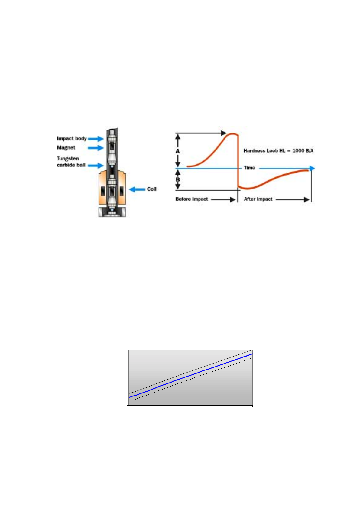
The rebound method indirectly measures the loss of energy of a so-called Impact Body. A
spring projects it towards the test piece and its spherical indenter str ikes the object ’s surface
at a defined speed. The indentation created absorbs a portion of the energy thereby
reducing its original speed. The sof ter the material t he larger the indent ation and the hig her
the loss of energy.
The velocities before and after t he impact are each measur ed in a non-cont act mode. T his is
accomplished by a small permanent magnet within the impact body ( see f igure) that induces
a voltage during its passage throug h a coil. The voltage created is proportional to the speed
as shown in the figure below.
Cross-cut of a typical impact device Voltage signal generated by the impact body
travelling through the coil. The signal is shown
before and after the impact.
The inventor of this method, D. Leeb, defined his own hardness value, the Leeb hardness
value. The Leeb hardness value, HL, is calculated from t he ratio of the im pact and rebound
speed according to: HL = 1000 B/A with A, B = speed before / after t he im pact
Who uses the Leeb value? The fact is that although the HL is the actual physical
measurement value behind this method rarely does a user indicate the Leeb value in his
specifications or test report s. Normally he reports a converted har dness value (HV, HB, HS,
2
HRC, HRB, N/mm
). Therefore conversion tables for various material groups are stored
within the instrument. The graphic below illustrat es such a conversion t able.
80,0
70,0
60,0
HRC
50,0
40,0
30,0
20,0
10,0
500 600 700 800 900
HL
D
Conversion of Hardness Leeb, HL, into HRC as a typical example for conversion tables stored in
rebound hardness testers. These curves are experimentally generated by material samples of
different hardness measured b
rebound and Rockwell test.
Page 3
FAQ 2: How does the MIC 10 use ultrasonics to measure hardness?
p
Conventional Vickers or Brinell hardness testing requires optical evaluation of the area of an
indentation produced by its indentor under a specified load. Testing using the UCI
(Ultrasonic Contact Impedance) met hod the diagonals of the test indentation, which have to
be known in order to determine the Vickers Hardness value, are not evaluated optically as
usual, but the indentation area is electronically detected by measuring the shift of an
ultrasonic frequency.
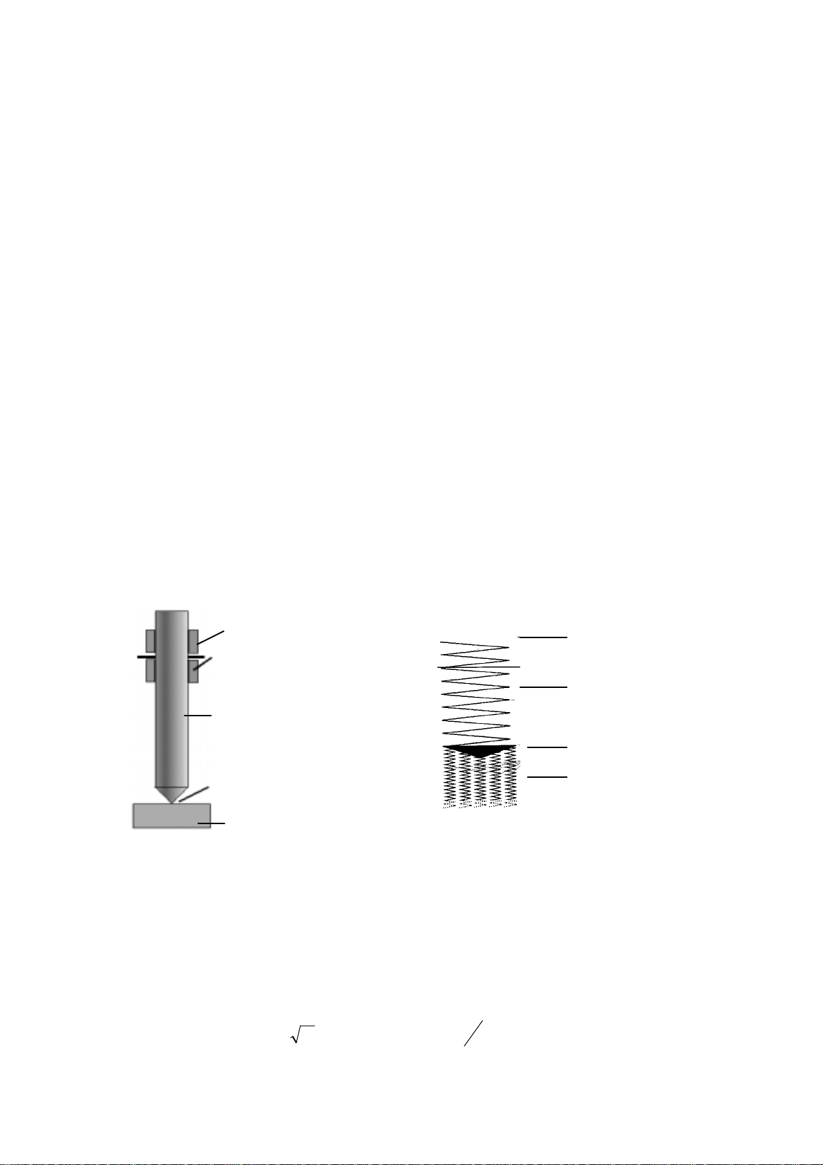
A UCI probe consists of a Vickers diam ond attached to the end of a metal rod. This rod is
excited into a longitudinal oscillation of approximately 70 kHz by Piezoelectric transducers.
Imagine the rod as a large spiral spr ing held at one end and f ree to oscillate at the resonant
frequency at the other end. At tached to the f ree end is a contact plate, t he Vick ers diamond.
Now picture the surface of the material to be comprised of a system of smaller spiral spring s
positioned vertically to the surface with the quantity of these springs r epresenting the elastic
properties of the material (Refer t o FAQ 11 for more information reg arding how to properly
calibrate the instrument f or a m aterials elastic modulus).
The diamond’s penetration depth into the ma terial is determined by the m aterial’s hardness
with a very hard material having a shallow indentation allowing only a few of these "at omic
springs" to contact the diamond r esulting in a slight frequency shift. On the other hand if a
softer part is tested, the diamond penetration is deeper and the frequency shift is more
significantly as additional "springs" are touched. This is the secret of UCI hardness testing:
the frequency shift is proportional to the size of the t est indentation produced by the Vickers
diamond.
Piezo Transducer
Piezo Receiver
Oscillating Rod
Vickers Diamond
Material
Schematic description of the UCI probe UCI principle in an imaginary experiment:
an oscillating spring in contact with material. The
large spring represents the oscillating rod, the contact
plate represents the diamond, the smaller springs
represent the material and its elastic constants.
Fixture
Spring
Contact Plate
Material S
rings
The equation below describes this basic relation in comparison to the definition of the
Vickers hardness value.
AEf
⋅≈∆
elast
HV =
F
A
Page 4

The graphic below illustrates the relationship of frequency shift to har dness.
900
700
HV
500
300
100
2 2,5 3 3,5 4 4,5 5
Frequency shift [kHz]
Vickers Hardness value versus frequency shift of the oscillating rod.
Page 5

FAQ 3: What is the proper technique for carrying out a hardness measurement?
DynaMIC Series Including the DynaPOCKET
Pressing the Loading Tube of the impact device of t he DynaPOCKET and DynaMIC grasps
and suspends the impact body. Upon pressing the Release Button a spring propels it
towards the part and hardness value is updated.
Aligning the impact device within 3° of being perpendicular to the surface is required. The
standard support rings provided with each Dyna D and Dyna E can be used to test convex or
concave radii greater than 30 mm (1.2 in.). The larger diameter of the Dyna G standard
support ring requires the r adius to be greater than 50 mm (2. 0 in. ).
Support rings are offered as accessories that can be used with the Dyna D and Dyna E
impact devices. They are available to cover the range of 10-30 mm (0.4 to 1.2 in.) f or t esting
the ID’s or OD’s of cylindrical and spherical shaped parts (see Dyna 41 and Dyna 42).
Custom support rings are also available on request.
MIC 10 Series
The recommended technique for using a handheld probe is to use one hand to steady the
probe at the bottom while the other hand applies the load in a slow and controlled manner.
Force is continuously applied until the end of the probe sleeve contacts the material at which
time the instrument displays the updated hardness value.
Caution: To prevent damage to the diamond care must be taken not to twist the
probe while the diamond is in contact with the test material.
To carry out a reading, the probe must be aligned perpendicular to within 5° of part’s
surface. Of course, the m ore precise t he alig nment t he mor e consist ent the result s. T o aid in
alignment the protection sleeve can be removed and replaced with various probe shoes. For
example a probe shoe with a V groove base is handy when testing cylindrical parts having a
radius of 3 - 75mm (.12 - 3.0 in.) And a flat pr obe shoe, although designed primarily to test
flat surfaces, also can be used in test ing radii greater than 75 mm (3.0 in.).
Page 6
FAQ 4: What model of your portable hardness testers will best solve my application?
Several factors enter in the decision as to what method and portable instrument packag e is
best suited for a particular applicat ion.
As with conventional hardness testers the size of the indentation produced by the portable
equipment is extremely important in det ermining its suitability for a hardness application. To
obtain accurate and repeatable readings the indentation must cover several grains of the
materials microstructure; must be proportionally larger than the surface roughness; and if
testing coatings or surf ace hardened components their thickness must be at least 10 times
larger than the indentation depth so as not t o be affected by the softer subst rate material.
The UCI method is recommended for testing fine grained material having any shape and
size. It is especially used where material properties are to be processed with narrow
tolerances, e.g. f or det ermination of strain hardening on dr op forged parts.
Rebound hardness testing is carried out on large, coarse grained mater ials, f or ged par ts and
all types of cast materials because the spherical tip of the impact device produces a r ather
larger indent than the Vickers diamond and therefore processes the characteristics of the
casting structure better.
With the small indent of the Microdur UCI probes, determination of the hardness can be
made on welded parts in the critical area of the weld, the heat affected zone (HAZ).
The Leeb and UCI methods can be influence by the mass and thickness of the part to be
tested. Therefore bot h of these factors must be considered in deter mining the best method
(refer to FAQ 5 for additional information) .
A number of probes and impact devices having diff erent test loads provide a large rang e of
applications.
Application UCI testing Rebound testing
Solid parts
Coarse grain materials
Steel and aluminium cast alloys
HAZ with welds
Tubes: wall thickness > 20 mm
Tubes: wall thickness < 20 mm
Inhomogeneous surfaces
Thin layers
+++
-++
o++
++ ++ ++
++ -
-+
++ -
Difficult to access positions
(++ especially suited / + well suited / o suited sometimes / - not recommended)
Applications for UCI and rebound hardness testing.
++ +
Page 7

FAQ 5: How can my parts mass and thickness affect the results and what are the minimum requirements?
The requirements f or the part’s thickness and mass are more demanding for the Rebound
(Leeb) method than they are for the UCI method. Each method is inf luenced diff erently but a
common solution is offered.
The DynaMIC / DynaPOCKET create a high force of about 900 N at the time of impact . T hin
or lightweight materials will flex under this large impact, altering the rebound of the impact
body from the surface typically causing the display of lower than actual hardness values.
Although the force of t he UCI is considerably less (98N f or the MIC-2010 probe) t he pr oblem
with this method is that thin or lightweight components can go into self-oscillation. What
occurs with the UCI method is an incorrect frequency shift to be measured causing
erroneous and erratic values.
A possible solution for either method is a machined support that precisely matches the
contour of part’s back surf ace to reinforce and make it rig id. Extremely thin materials may
also require the use of a light grease or paste to couple the part t o the support.
The table below is provided as a guideline for determining m ass and support requirements.
Dyna D & E DynaG UCI Probes
No support required > 5 Kg
> 11 lbs.
Requires Support 2 to 5 Kg
4.4 to 11 lbs.
Requires Support & coupling paste .05 to 2 Kg
0.1 to 4.4lbs.
> 15 Kg
33 lbs.
5 to 15 Kg
11 to 33 lbs.
.5 to 5 Kg
1.1 to 11 lbs.
0.3 Kg
0.7 lbs.
0.1 to 0.3 Kg
0.2 to 0.7 lbs.
0.01 to 0.1 Kg
0.02 to 0.22 lbs.
In addition to the test object’s minimum mass, the wall thick ness also plays an important part
in selection of the test method. It can influence the hardness value even when the test object
is solid and weighs a few tons. Wall thickness of tubes, pipelines or valves is critical for
portable hardness testing. As an example, a thin wall will react like the skin of a drum when
an impact body strikes it.
The following table is offered to provide guidelines f or wall thickness however certain part
geometry could stiff en the test piece allowing a thinner wall.
Hardness testing
method
Rebound 20 mm 0.79
UCI 2-3 mm 0.08 – 0.12
Wall thickness
in mm
Wall thickness
in inches
Page 8

The graphic below effectively illustrates t he deviation of a Vickers test compared to that of
the DynaD for varying wall thickness. Note that above 20mm there is good correlation
between the different test methods indicating that the rebound tester provides a true value.
Page 9

FAQ 6: What surface finish is needed and how can I properly prepare it?
All hardness test methods require smooth surfaces free of rust, paint, oil or protective
coatings. The indentation depth m ust be lar ge in comparison to the surface roughness.
Surface preparation can be performed using a battery driven, high speed (>12,000 rpm)
handheld grinder. However, care must be taken not to alter the surface hardness by
overheating or cold working.
DynaMIC Series Including the DynaPOCKET.
Coarse surfaces will tend to lower the measured value and cause a great er variation within a
set of measurements. The graphic below illustrates the affects of variation in the Vickers
values as a result to varying degrees of surface roughness that can be expected when using
a DynaMIC with DynaD impact device or a DynaPOCKET.
MIC 10 Series
Size of the indentations produced can vary greatly due to the extensive range in hardness
possible with the MIC 10 and the available probe loads ranging from 0.3 to 10.0 kg f. The
MIC 10 provides very fast testing allowing the operator to q uickly take a set of 5-10 readings.
Experience has shown that the average of the set can be repeated if the surface has been
sufficiently prepared.
Page 10

FAQ 7: How do I select the best MIC 10 probe for my application?
The UCI method is best suited for testing homogeneous materials due to the small size of
the indentations created. Five diff erent loads (0. 3, 0.8, 1.0, 5.0 and 10 k g f ) are employed by
the various models of UCI probes. The table below is off ered as a g eneral guide t o selecting
the appropriate probe for a variety of applications.
Load Available Models Advantage or Benefit Typical Applications
98 N
10 kgf
50 N
5 kgf
10 N
1 kgf
8 N
0.8 kgf
3 N
0.3 kgf
MIC-2010
Standard Length
Handheld Style
MIC-205
Standard Length
Handheld Style
MIC-205L
Extended Length
Handheld Style
MIC-205S
Short Probe
Handheld Style
MIC-201
Standard Length
Handheld Style
MIC-201L
Extended Length
Handheld Style
MIC-201S
Short Probe
Handheld Style
MIC-211
Motor Probe Style
MIC-2103
Motor Probe Style
Largest indentation requiring only
minimal surface preparation
Solves most general applications
30mm (1.2 in.) extended length
designed for clearing obstacles.
Reduced length to 90 mm (3.5 in.)
electronics in separate housing for
minimum height.
Load is easy to apply; provides
control to test on a sharp radius
30mm (1.2 in.) extended length
designed for clearing obstacles.
Reduced length to 90 mm (3.5 in.)
electronics in separate housing for
minimum height.
Use with urethane fixtures for
complex shapes
Shallowest indentation Layers, e.g. copper or chromium
Small forgings & HAZ weld testing
Induction or carburized machined
parts, e.g. camshafts, turbines,
HAZ weld testing
Measurement in grooves & gears
ID testing of pipes or tubes
Ion-nitrided stamping dies and
molds, forms, presses, thin walled
parts
Bearing raceways & gears
ID testing of pipes or tubes
Finished precision parts e.g.
gears, & bearing raceways
layers on steel cylinders
(≥ 40 µm),
Copper Rotogravure cylinders,
Coatings, Hardened layers
(≥ 20 µm)
UCI (MIC 10) probe models, their benefits and typical applications.
Page 11

FAQ 8: How do I select the right DynaMIC impact device for my application?
Our series of rebound hardness tester s includes the DynaMIC and DynaMIC DL inst ruments
with interchangeable DynaD, DynaE and DynaG impact devices. The DynaPOCKET is an
integrated model with an equivalent DynaD device built into the electr onics.
Although a variety of impact devices are off ered, the DynaD with a 3 mm tungsten carbide
tip solves the majority of common applications. The Dyna E is similar mechanically to the
DynaD but uses a diamond to provide a long service life for testing very hard part s (650 HV /
56 HRC or higher).
The DynaG impact body is much larger in size compared to the other two devices, which is
necessary because it creates impact energy nine times greater and has a larger indentor .
Typical applications for each device are listed in the f ollowing t able:
Model Indenter Force
(N mm)
DynaD
DynaPOCKET
DynaE 3 mm Spherical Diamond 12 >50 HRC, e.g. forged and hardened steel mill rolls
DynaG 5 mm Tungsten Carbide Ball 90 <650 HB, e.g. Large castings and forgings, lower
DynaPOCKET and DynaMIC Series Impact Devices, their benefits and typical applications
3 mm Tungsten Carbide Ball 12 General purpose testing of homogeneous material
surface requirements
Typical Applications
Page 12

FAQ 9: Does gravity affect the results of the instrument?
NO. All of our portable equipment is unaffected by gravitational affects allowing complete
and uninterrupted testing around t he cir c um ference of a cylinder.
DynaMIC Series Including the DynaPOCKET
All Leeb instruments currently on the market with the exception of the DynaMIC and
DynaPOCKET are affected by gravity. The first inst ruments required the operator to use a
lookup table and add a correction factor to the displayed value based on the impact devices
orientation. Competitive instrument now on the market require the operat or to input the test
direction prior to carrying out a measurement so that the correction factor is added
automatically to the displayed value.
However, what sets the DynaMIC and DynaPOCKET above all other Leeb instruments is our
patented Autobalancing featur e. Special signal processing not only calculates the hardness
value using the ratio of the voltages r equired by the LEEB principle but also analyzes their
phases to automatically compensate for changes in orientation. Eliminating the additional
step to input direction improves productivity and assures the accuracy of the results. Due t o
the patented signal processing there is no need for any manual correction for the impact
direction.
MIC 10 Series
The principle of the UCI method employed by the MIC 10 has always been unaffected by
gravitational affect s.
Page 13

FAQ 10: Does your portable hardness test equipment meet ASTM standards?
DynaMIC Series Including DynaPOCKET
The DynaMIC and DynaPOCKET conform to ASTM Standard A956-00 ent itled:
Standard Test Method for Leeb Hardness Testing Of St eel Pr oducts.
MIC 10 Series
At this time the UCI principle of the MIC 10 is not covered under any ASTM standard.
Page 14

FAQ 11: When is it necessary to calibrate the instrument and how is this accomplished?
Elastic modulus (Young’s Modulus) is determined by the bonding forces of a material’s
atoms. It’s a measure of a material’s ability to return to it original condition after a load is
applied and then removed. Elastic modulus is an important factor when converting values of
different hardness tests methods and its influence must be taken into consideration to
properly calibrate our portable hardness testers.
DynaMIC Series Including the DynaPOCKET
To calibrate the DynaPOCKET, the operator selects from one of nine material groups from
the table below. Each material group represents materials having a similar elastic modulus
and for most applications the results obtained are sufficiently accurate. However, material
groups were generated using a limited num ber of alloys and therefor e should be considered
as a rough calibration.
The DynaMIC also provides the operator the selection from the same m aterial groups. But
for more demanding applicat ions were tight tolerances are required it is possible to use the
calibration feature to allow for a specific material. All that is required is a sample of the
material which has been tested with the method specified, e.g. Brinell, Rock well C, Rockwell
B, etc. To perform the calibration, several readings are taken on the sample and the
DynaMIC’s displayed average value is adjusted to the actual “real” hardness. This
establishes a calibration offset reference value for that specific material that can be used to
recalibrate the instrument at a later time.
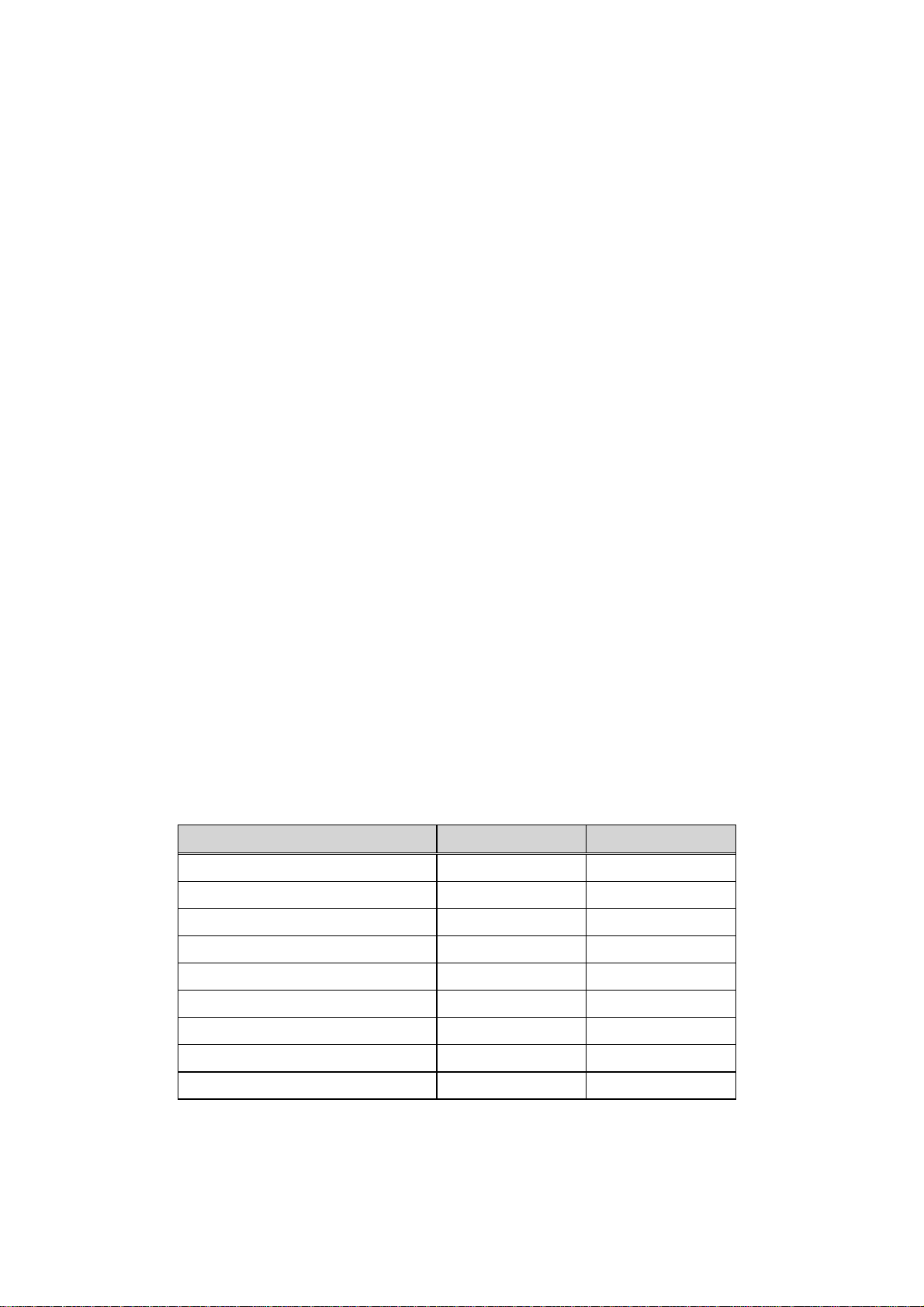
Material Group HV HB HRB HRC HS N/mm
1 Steel –
Plain, Low Alloy or Cast
2 Tool Steel D, E D, E
3 Stainless Steel D D D D
4 Gray Cast Iron D, G
5 Nodular Cast Iron D, G
6 Cast Aluminium D D
7 Brass D D
8 Bronze D
9 Copper D
Material groups and available DynaMIC conversions
Letter indicates the impact device model ( D also indicates the DynaPOCKET)
D, E, G D, E, G D, E, G D, E, G D, E, G
2
MIC 10 Series
UCI probes compatible with the MIC 10 series are calibrated on steel t est blocks having an
elastic modulus of 210,000 MPA (30
106 PSI). Because non-alloyed or low alloyed steels
·
have a similar elastic modulus, accurate results are obtained with t he standard calibrat ion. In
many cases, the difference in elastic modulus of medium and high alloy steels is so
insignificant that the er r o r cr eated falls within the allowable tolerances of the part.
Page 15

However, the elastic modulus for non ferr ous mat erials req uir e special calibrat ions. All that is
required is a sample of the material which has been tested with the method specified, e.g.
Brinell, Rockwell C, Rockwell B, etc. To per form the calibration, several readings are tak en
on the sample and the MIC 10 displayed average value is adjusted to the actual “real”
hardness. This establishes a calibration off set reference value for t hat specific material that
can be used to recalibrate the instrument at a later time.
Calibration offset values are ref erenced from a 0000 value for st eel. Note that they can be
either a positive or negative value. The following table contains a listing of approximate
calibration values that can be referenced for som e common materials.
Material Calibration Offset Value
Aluminium -8800
Chromium +0250
Copper -5800
Cast iron -4800
Titanium -6500
300 Series Stainless -1500
400 Series Stainless -0900
Approximate UCI Calibration Offset Values
Page 16

FAQ 12: What is the accuracy I can expect and how is the equipment’s performance verified?
Assuming that your parts have adequate thickness and mass for the chosen technique other
factors relating to a specific application (e.g. shape, surface condition, the homogeneous
nature of the material, et c.) can affect the overall accuracy you can expect to obtain.
The performance of any hardness tester can be assessed indirectly using standardised
hardness reference blocks and by employing stat ist ical m et hods.
DynaMIC Series Including the DynaPOCKET
The acceptable performance is based on 5 measurements on a certified Leeb test block
having a nominal value of approximately 765 HL. The average of the 5 measurements
should be within ±5 HL of the test blocks certified value.
A higher than acceptable average test block value indicates:
• The tungsten carbide ball is flat tened and the impact body requires replacement.
• The area of the test block is completed use and should be replaced.
A lower than acceptable average test using block value indicates:
• A dirty impact device guide tube; clean with the supplied brush.
• The tungsten carbide ball is crack ed and t he im pact body requires replacement.
• The support ring has a worn rubber pad and requir es r eplacem ent.
MIC 10 Series
The specification for t he MIC 10 is stated using cer tified Vick ers test blocks. The averag e of
5 readings should be within ±3.6% of its certified value when using a ridged support such as
the MIC-222 test stand. Testing freehand a minimum of 10 r eadings should be averaged and
the tolerance is ±5%.
As a reference for comparison the ±3.6% HV range achievable with the MIC 10 Series
converts to the Rockwell C scale as listed in the table below. Also to compare it to bencht op
Rockwell testers the required repeatability for these hardness levels as defined by ASTM
E18 is also listed.
64 HRC
45 HRC
25 HRC
MIC 10 with Fixturing
(3.6% of 5 readings)
± 1.0 HRC ± 1.5 HRC ± 0.5 HRC
± 1.5 HRC ± 2.0 HRC ± 1.0 HRC
± 1.5 HRC ± 2.0 HRC ± 1.0 HRC
MIC 10 Freehand
(5.0% of 10 readings)
Rockwell Tester
per ASTM E18
Page 17

FAQ 13: How thin a coating or surface treatment can I measure using the
MIC 10?
The UCI method is suitable for testing t hin nitrided or carburized surf ace hardened layers or
coatings such as chrome. To ensure that the r eading is unaf fected by the substrate mat erial,
the penetration depth of the Vick ers diamond has to be considered. As a rule, t he thickness
of the layer should be a minimum of ten times t he indentation depth. But nevertheless, the
total thickness of the test piece should be at least 2-3 m m otherwise the sample has to be
coupled to a support plate.
The minimum wall thickness of a layer / coat ing for hardness testing with the UCI (Vickers)
[N]loadTest
0.062d ⋅=
[mm]
[HV]Hardness
hardness tester depends on the probe load and the (estimated) hardness of the test
material. The depth of penet ration (d) can be calculated using the following equation:
And the minimum thickness (s) as mentioned above should be at least 10 times the
penetration depth (d). s > 10d
The table below lists the depth of penetration using the above equation and minimum
thickness based on the times ten rule for various hardness levels when using the MIC-2103
(3N or 0.3kgf load) and the MIC-211 (8.6 N or 0.8 k gf load) motor ized probes. Keep in mind
that the shallow indentations produced by these light loads require a very stringent sur face
finish.
Probe
MIC-2103
(3 N)
MIC-211
(8.6 N)
Hardness Penetration depth Min. Thickness
[HV]
200 7,6 76
400 5,4 54
600 4,4 44
800 3,8 38
1000 3,4 34
200 12,9 129
400 9,1 91
600 7,4 74
800 6,4 64
1000 5,7 57
µm µm
Page 18

FAQ 14: How do the sizes of the indentations produced by the various portable hardness testers compare?
In general, the larger the area sampled by an indentation the more consistent the test
results. Variations in microstructure of non-homogeneous materials or those comprised of
large coarse grains are averaged providing consistent results. Another advantage of a larg er
indentation is less demand is placed on the surface finish thereby reducing the time for
preparing the surface.
In comparison, the indentations yielded by the various impact devices of rebound test ers are
much larger than those created by any UCI probe. W hen testing large casting s and forg ings
the rebound tester is recommended. T esting small components compr ised of homogeneous
materials or those having received surface hardening processes require the shallower
indentations produced by UCI probes.
Comparison of indentation width for Dyna D impact device and MIC 2010, MIC 205, MIC 201probe
The tables below are provided to compare the indentation width and depth of rebound
impact devices and UCI probes at three levels of hardness.
Dyna G
6 mm ball,
90 N mm
64 HRC 350 152 107 48 25
55 HRC 898 449 175 124 56 28
30 HRC 1030 541 249 175 79 41
Approximate indentation width (in µm) at different hardness levels.
Dyna G
6 mm ball,
90 N mm
800 HV 16 22 16 7 4
600 HV 63 28 25 20 9 5
300 HV 83 35 35 25 11 6
Approximate indentation depth (in µm) at different hardness levels.
Dyna D
3 mm ball
11 N mm
Dyna D
3 mm ball
11 N mm
MIC 2010
98 N
MIC 2010
98 N
MIC 205
50 N
MIC 205
50 N
MIC 201
10 N
MIC 201
10 N
MIC 2103
3 N
MIC 2103
3 N
Page 19

FAQ 15: What is an effective method to measure the HAZ on welded parts?
Hardness measurements in the HAZ determine whether the welding was done properly or if
a post weld heat treatment is required. Lim itations must be placed on the hardness of the
base metal, heat-affected zone (HAZ) and weld metal. If too hard, they will not have
sufficient ductility f or t he service conditions, or their corrosion resistance may be impaired.
The HAZ may only be 3mm wide and contains several zones differing metallurgically.
Therefore a small indention is desirable to detect the narrow band of t he hardened areas.
Performing a Brinell te st or even using t he Telebrineller (commonly used in re fineries) results
in quite a large indentation that averages several zones. This would mask the presence of
this undesirable condition.
This is an excellent application for the MIC 10 in combination with either t he MIC-205 or MIC2010 probe due to their design and the small indentations they create. With the diamond
protruding from the probe sleeve the operator can precisely position it. The small
indentations produced make it possible to detects the undesirable condition so that a post
weld heat treat can be used to correct the problem.
A MIC-227 test support is also available to accurately index across the pipe to record the
hardness progression.
 Loading...