

Page 1

DynaPOCKET
Technical Reference and Operating Manual
Ident-No. 28 674
Page 2

Content
This Issue 03, 04/2005 applies to the software version V 01.01.01
The software version is indicated in the display (ref. chapter 3.3).
Subject to change without notice.
0-2 Issue 03, 04/2005 Krautkramer DynaPOCKET
Page 3

Content
1 Introduction ...................................... 1 -1
1.1 Safety information .................................. 1 -2
Batteries ................................................... 1 -2
Software ................................................... 1 -2
1.2 About this manual .................................. 1 -3
Important information ................................ 1 -3
1.3 Layout and presentation in this manual 1 -4
Attention and note symbols ...................... 1 -4
Listings ..................................................... 1 -4
Operating steps ........................................ 1 -4
1.4 Prerequisites for hardness testing ......... 1 -5
Operator training ....................................... 1 -5
Technical test requirements ...................... 1 -6
Choice of the appropriate test equipment .. 1 -6
1.5 Krautkramer DynaPOCKET ..................... 1 -7
1.6 Important information about hardness
testing using the DynaPOCKET ............. 1 -9
Test material ............................................. 1 -9
The rebound method ................................. 1 -9
Conversion of hardness values ............... 1 -10
2 Scope of supply and accessories .. 2 -1
2.1 Scope of supply ...................................... 2 -3
2.2 Recommended accessories ................... 2 -5
2.3 Spare parts requirements ....................... 2 -6
3 Operation .......................................... 3 -1
3.1 Preparation .............................................. 3 -2
Inserting batteries ..................................... 3 -2
3.2 Fundamental principles of operation .... 3 -3
Display and keys ...................................... 3 -3
How to handle the impact device .............. 3 -5
3.3 Hardness measurement .......................... 3 -6
Switch-on .................................................. 3 -6
Switch-off ................................................. 3 -6
Carrying out a measurement ..................... 3 -6
Closing a measurement set ...................... 3 -7
Deleting measured values ......................... 3 -7
Krautkramer DynaPOCKET Issue 03, 04/2005 0-3
Page 4

Content
3.4 Selecting instrument settings ................ 3 -8
Setup mode .............................................. 3 -8
Measurement mode and
display of measured values ...................... 3 -8
Material group ........................................... 3 -9
Hardness scale ....................................... 3 -10
Conversion .............................................. 3 -11
4 Maintenance and care ...................... 4 -1
4.1 Care ......................................................... 4 -2
Caring for the instrument ........................... 4 -2
Caring for rechargeable batteries ............... 4 -2
Charging the batteries ............................... 4 -2
How to handle alkaline batteries ................ 4 -3
4.2 Maintenance ............................................ 4 -3
Impact device ........................................... 4 -3
5 Function check and
troubleshooting ................................ 5 -1
5.1 Checking the function ............................. 5 -2
5.2 Troubleshooting ...................................... 5 -2
Error codes ............................................... 5 -3
6 Technical data .................................. 6 -1
Housing .................................................... 6 -2
Display and keypad .................................. 6 -2
Power supply and operating time ............... 6 -3
Ambient conditions ................................... 6 -3
Evaluation ................................................. 6 -4
0-4 Issue 03, 04/2005 Krautkramer DynaPOCKET
Page 5

Content
7 The rebound hardness testing
method .............................................. 7 -1
7.1 The hardness testing method ................ 7 -2
7.2 Conversion of hardness values .............. 7 -3
Material groups ......................................... 7 -4
Application ranges of the conversion tables . 7 -5
7.3 The treatment of test material ................ 7 -6
Surface quality .......................................... 7 -6
Curved surfaces........................................ 7 -6
Measurements on small objects ............... 7 -6
Minimum wall thicknesses ........................ 7 -6
7.4 Information about the
statistical evaluation ............................... 7 -8
8 Annex ................................................ 8 -1
8.1 EU declaration of conformity ................. 8 -2
8.2 Manufacturer/Service addresses ............ 8 -2
9 Index .................................................. 9 -1
Krautkramer DynaPOCKET Issue 03, 04/2005 0-5
Page 6

0-6 Issue 03, 04/2005 Krautkramer DynaPOCKET
Page 7

Introduction 1
Krautkramer DynaPOCKET Issue 03, 04/2005 1-1
Page 8

Introduction Safety information
1.1 Safety information
The DynaPOCKET is designed and tested according to
DIN EN 61 010 Part 1, March 1994, “Safety requirements for electric measuring, control and laboratory
equipment“, and was technically in perfectly safe and
faultless condition when leaving the manufacturing
works.
In order to maintain this condition and to ensure a safe
operation, it is absolutely necessary that you read the
following safety information before putting the instrument into operation.
A Attention:
The DynaPOCKET is an instrument for materials
testing. Any use for medical applications or other
purposes is not permitted!
The instrument may only be used in industrial
environments.
Batteries
The DynaPOCKET can be operated with AAA-sized
AlMn cells or rechargeable NiCads and NiMH batteries.
NiCads or NiMH batteries can not be charged within
the instrument. They must be charged with a specifically approved external battery charger.
For information on how to properly handle the batteries,
please refer to chapter 4
Maintenance and care
.
Software
According to the present state of the art, software is
never completely free from errors.
Before using any software-controlled test equipment,
you should ensure that the required functions operate
perfectly as intended.
If you have any questions about the use of your test
equipment, please contact your local GE Inspection
Technologies representative.
1-2 Issue 03, 04/2005 Krautkramer DynaPOCKET
Page 9

About this manual Introduction
1.2 About this manual
In the following section you will learn how to use this
manual. Please read through these instructions carefully carefully to operate all functions of the
DynaPOCKET quickly and reliably.
This will enable you to take full advantage of the
instrument’s capabilities. Also, you will avoid any incorrect test results due to malfunctions or operating errors. Such incorrect test results may cause personal
injuries or material damages.
Important information
Even if you should be familiar with hardness testing
methods, please review the information in the chapters
1.4, 1.5 and 7.
In chapter 1.4, you will find important limitations and
prerequisites for hardness testing in general (training,
knowledge of the specific technical test requirements
and limits, choice of the appropriate test equipment).
In chapter 1.5, you will find complete information about
hardness testing using the DynaPOCKET that must
always be followed to ensure correct measurement
results.
Chapter 7 describes the rebound hardness testing
method.
Krautkramer DynaPOCKET Issue 03, 04/2005 1-3
Page 10

Introduction Layout and presentation in this manual
1.3 Layout and presentation in
this manual
To make it easier for you to use this manual, all operating steps, notes, etc. are always presented in the same
way. This will help you find individual pieces of information quickly.
Attention and note symbols
A Attention:
The Attention symbol indicates peculiarities and
special aspects in the operation which could affect the
accuracy of the results.
H Note:
Note contains e.g. references to other chapters or
special recommendations for a function.
Listings
Listings are presented in the following form:
❚ Variant A
❚ Variant B
❚ ...
Operating steps
Operating steps appear as shown in the following
example:
– Position the DynaPOCKET vertically to the
surface to be tested.
– Use your thumb to press the release button.
1-4 Issue 03, 04/2005 Krautkramer DynaPOCKET
Page 11

IntroductionPrerequisites for hardness testing
1.4 Prerequisites for hardness
testing
This operating manual contains all essential information on how to operate the DynaPOCKET. In addition,
there are a number of factors which affect the results.
A description of these factors would go beyond the
scope of an operating manual. The following list therefore contains only the three most important conditions:
❚ operator training
❚ knowledge of special technical test requirements
and limits
❚ choice of the appropriate test equipment
A Attention:
Lack of knowledge of the above-mentioned subjects
may lead to incorrect test results and thus have unforeseeable consequences.
Operator training
The reliable and safe operation of a hardness testing
device requires a proper training in the field of materials testing.
A proper training comprises for example adequate
knowledge of:
❚ hardness testing on metallic materials,
❚ effects due to material properties, especially due to
the microstructure, on hardness testing and on the
corresponding choice of the appropriate hardness
tester,
❚ limits relating to the use of conversion of different
hardness values such as Vickers, Rockwell and
Brinell,
❚ effects of surface finish on the hardness value,
❚ effects of the test load on the determined hardness
value.
Krautkramer DynaPOCKET Issue 03, 04/2005 1-5
Page 12

Introduction Prerequisites for hardness testing
Technical test requirements
Every hardness test is subject to specific technical
test requirements. The most important ones are :
❚ definition of the scope of test
❚ choice of the appropriate test method
❚ consideration of material properties
❚ determination of limits for evaluation
Choice of the appropriate test equipment
It is the task of those with overall responsibility for
testing to ensure that the inspector is fully informed
about the technical test requirements. Moreover, a
clear and thorough interpretation of the corresponding
test specifications is absolutely necessary.
Information about test methods and test specifications
may be obtained, for example, from various institutions,
industrial enterprises and authorities.
1-6 Issue 03, 04/2005 Krautkramer DynaPOCKET
Page 13

IntroductionKrautkramer DynaPOCKET
1.5 Krautkramer DynaPOCKET
The Krautkramer DynaPOCKET is a handy and easyto-use rebound hardness tester enabling the user to
carry out tests quickly and effortlessly.
You can use the DynaPOCKET to carry out measurements anywhere and in any direction; the direction
does not have to be set in advance.
The DynaPOCKET is mainly suitable
❚ for measuring the hardness of low-alloy or unalloyed
steels,
❚ for measuring the hardness of high-alloy steels,
❚ for measuring the hardness of nonferrous metals.
The DynaPOCKET operates according to the rebound
method (according to ASTM standard A 956). In this
method, an impact body is impelled against the test
surface by spring force.
Impact and rebound speeds are measured in non-contact mode and the hardness value is calculated on the
basis of these two measurements. The hardness value
is immediately displayed. Apart from this, a high reproducibility of the test results is ensured.
The DynaPOCKET has only two operating keys to
carry out all functions.
The large display indicates the current single value or
the statistical average of a measurement set, depending on the selected mode.
Krautkramer DynaPOCKET Issue 03, 04/2005 1-7
Page 14
Introduction Krautkramer DynaPOCKET
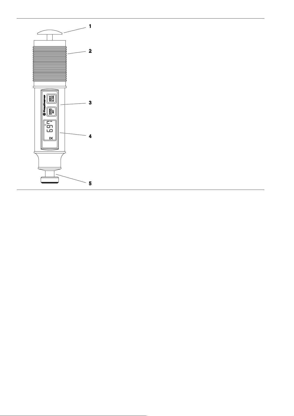
1 Release button
2 Loading tube
3 Operating keys
4 Display
5 Impact device with test attachment
1-8 Issue 03, 04/2005 Krautkramer DynaPOCKET
Page 15

Important information about hardness testing using the DynaPOCKET Introduction
1.6 Important information about
hardness testing using the
DynaPOCKET
The following section contains a summary of the most
important technical test requirements that you always
have to observe in order to obtain reliable and reproducible measurement results.
Test material
Surfaces must be free from any impurities (oil, dust,
rust, etc.). Rough surfaces lead to a greater variation
of the single values. If necessary, prepare rough surfaces, using our grinding set MIC 1060 (ref. chapter 2).
Test objects having a mass of at least 5 kgs can be
tested without any additional supports; objects weighing less require a support to which they have to be
tightly coupled. Please use large, inflexible and rigid
metal supports for this purpose.
The test objects should have a minimum wall thickness of 20 mm. We recommend the use of the UCI
hardness tester MIC 10 for test objects having thinner
wall thicknesses.
A Attention:
A yielding or springiness of the test objects may lead
to measuring errors! Please also refer to chapter 7.3.
The rebound method
The rebound method is a dynamic method with a very
high reproducibility of the measurements. The rebound
method does not replace the classical Brinell hardness
testing or other standardized methods, but rather
complements them.
The remaining energy of an impact body is measured
after rebounding from the material surface. Please observe that the loss of energy is also effected by the
material’s mechanical properties, i.e. mainly on its
modulus of elasticity or Young’s modulus.
The direct comparison with results obtained from standardized hardness measurements on specific materials
is therefore important for the evaluation of the measuring accuracy of the rebound method.
Krautkramer DynaPOCKET Issue 03, 04/2005 1-9
Page 16

Introduction Important information about hardness testing using the DynaPOCKET
A Attention:
It is absolutely necessary that you set your
DynaPOCKET to the appropriate material group
before testing (ref. chapter 3.4).
The material group for low-alloy or unalloyed steel is
defined as default setting in the instrument.
Please also read chapter 7 on the rebound method.
A Attention:
You should not carry out hardness measurements
twice at the same test position, otherwise faulty measurements are possible due to the surface hardening.
The distance between the test positions should be at
least 3 mm.
Conversion of hardness values
The conversion of the HL value determined according
to the rebound method into standard hardness scales
is carried out on the basis of defined conversion tables
depending on the material group.
The conversion into tensile strength values is made
according to DIN 50150 on the basis of the HB values.
You should carry out conversions only
❚ if the specified test method cannot be applied (for
example because there is no suitable instrument
available),
❚ if it’s not possible to section the part to perform the
specified test method.
Please observe the limitations regarding the conversion into DIN 50150.
A Attention:
Any illegal or unacceptable conversions may lead
to grave errors in the interpretation of measurement results.
1-10 Issue 03, 04/2005 Krautkramer DynaPOCKET
Page 17

Scope of supply and accessories 2
Krautkramer DynaPOCKET Issue 03, 04/2005 2-1
Page 18

Scope of supply and accessories Scope of supply
This chapter informs you about the scope of supply in
our standard package and the accessories available for
the DynaPOCKET.
It describes
❚ accessories included in the scope of supply of our
standard package
❚ recommended accessories
❚ spare parts requirements
2-2 Issue 03, 04/2005 Krautkramer DynaPOCKET
Page 19

Scope of supply Scope of supply and accessories
2.1 Scope of supply
Product name Description Order no.
DynaPOCKET Plus DynaPOCKET Plus – Portable hardness tester 35 158
according to the rebound method with an integrated
impact device D and digital display of the
measured value in HV, HB, HRB, HRC, HS, HL or
N/mm², including hardness reference block
consisting of:
Basic instrument DynaPOCKET 35 159
Hardness reference block MIC D 62 34 394
Operating manual German/English 28 674
Quick Reference Guide German/English 28 675
Transport case 09 554
Cleaning brush 34 420
2 AlMn batteries (type AAA) 100 612
Test attachment dia. 13.5 mm 34 656
Krautkramer DynaPOCKET Issue 03, 04/2005 2-3
Page 20

Scope of supply and accessories Scope of supply
Product name Description Order no.
DynaPOCKET DynaPOCKET – Portable hardness tester 35 114
according to the rebound method with an integrated
impact device D and digital display of the
measured value in HV, HB, HRB, HRC, HS, HL or
N/mm²
consisting of:
Basic instrument DynaPOCKET 35 159
Operating manual German/English 28 674
Quick Reference Guide German/English 28 675
Transport case 09 554
Cleaning brush 34 420
2 AlMn batteries (type AAA) 100 612
Test attachment dia. 13.5 mm 34 656
2-4 Issue 03, 04/2005 Krautkramer DynaPOCKET
Page 21

Recommended accessories Scope of supply and accessories
2.2 Recommended accessories
Product name Description Order no.
MIC 300 Technical book on hardness testing (German only) 28 837
MIC 1060 Grinding set for surface treatment 34 380
Dyna 41 1 set (5 pieces) of test attachments 34 536
for cylindrical surfaces
Dyna 42 1 set (5 pieces) test attachments 34 539
for spherical surfaces
Krautkramer DynaPOCKET Issue 03, 04/2005 2-5
Page 22

Scope of supply and accessories Spare parts requirements
2.3 Spare parts requirements
Product name Description Order no.
2 AlMn batteries (type AAA) 100 612
MIC D 62 Hardness reference block 620 HV100 34 393
MIC D 62-MPA Hardness reference block 620 HV100, 34 573
certified by the material testing institute MPA
Cleaning brush for impact device D 34 420
Standard test attachment for impact device D 34 312
Test attachment for impact device D, dia. 13.5 mm 34 656
Impact body D, new 34 443
Impact body D, exchange replacement by 34 572
GE Inspection Technologies Service
2-6 Issue 03, 04/2005 Krautkramer DynaPOCKET
Page 23

Operation 3
Krautkramer DynaPOCKET Issue 03, 04/2005 3-1
Page 24

Operation Preparation
3.1 Preparation
Inserting batteries
You can operate the DynaPOCKET with AAA-sized
AlMn batteries or rechargeable NiCd or NiMH batteries.
You need 2 pieces of each. AlMn batteries are recommended for the longest operating time.
– Open the cover of the battery compartment.
– Insert the batteries while observing the correct
polarity as shown in the battery compartment.
– Replace the lid and snap the cover back in place.
The lock must perceptibly snap in.
H Notes:
Remove the batteries from the instrument if you’re not
going to use it for a longer period of time!
Used or defective batteries are special waste and must
be disposed of according to the legal requirements!
The following icon indicates the battery voltage is getting too low:
In this case, exchange the batteries immediately. The
DynaPOCKET automatically switches off if the battery
voltage is too weak to ensure reliable operation. It may
happen that the instrument cannot be switched on
again without battery exchange.
H Note:
If you remove the batteries from the instrument for
more than about 3 minutes, the last settings are lost
(e.g. measurement mode and hardness scale).
You will find more information about batteries in
chapter 5.1.
3-2 Issue 03, 04/2005 Krautkramer DynaPOCKET
Page 25
Fundamental principles of operation Operation
3.2 Fundamental principles of
operation
Display and keys
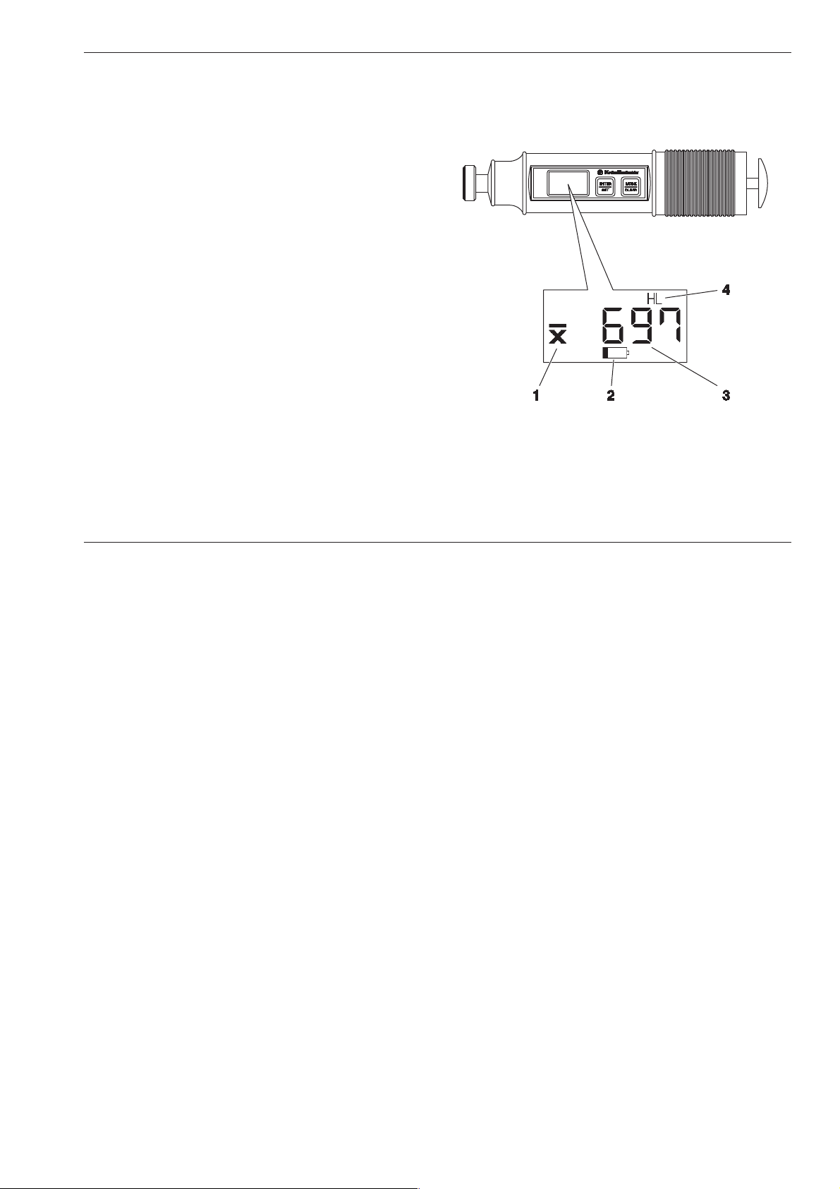
The display consists of the following areas:
1 Average
If you have selected the measurement set mode,
the icon for average value is displayed.
2 Battery
The battery voltage icon flashes to indicate that the
batteries require replacement.
3 Measured value
The measured hardness value (or the statistical
average with measurement sets) is shown in large
digits in the middle of the display. This area also
applies to other text displays when selecting default
settings, and for error codes.
4 Hardness scale
The selected hardness scale is displayed in the
area above or below the measured value.
Krautkramer DynaPOCKET Issue 03, 04/2005 3-3
Page 26

Operation Fundamental principles of operation
The DynaPOCKET has two keys which you can use
to carry out all functions. Each activates several different functions, depending on the current mode of the
instrument.
Key ENTER/SET
Mode Function
Instrument off Switch-on
Single measurement None
Measurement set Start new measurement set
Setting Set selected parameter
Key MODE/CLEAR
Mode Function
Instrument off Switch-on
Single measurement None
Measurement set Display and delete last value
Setting Apply setting and
select the next parameter
3-4 Issue 03, 04/2005 Krautkramer DynaPOCKET
Page 27

OperationFundamental principles of operation
How to handle the impact device
Ensure the use of the propriate test attachment for
your application.
– Press either key to switch the instrument on.
– Place the DynaPOCKET with the test attachment on
a flat surface.
– Load the impact device by pressing the blue cylinder
down to the end stop and then moving it slowly back
to the initial position.
– Place the DynaPOCKET vertically on the test
surface.
– Use your thumb to press the release button.
The measured value (or the statistical average) is
digitally displayed:
A Attention:
Do not load the impact device at the actual test location but (due to surface hardening) at another location
(e.g. table or another part of the test object). After that,
place it at a new test position for another measurement.
Do not perform two measurements at the same test
location, otherwise measuring errors may occur due to
surface hardening effects. Maintain a minimum spacing
of 3 mm.
The loading tube should not be pushed in (loading tube
must be at the farthest stop) when releasing for measurement.
Test attachments Dyna 41 and Dyna 42
The test attachments Dyna 41 and Dyna 42, which you
use for a better positioning on curved surfaces, have a
special geometry for use on cylindrical surfaces or
spherical surfaces (ref. chapter 2).
Krautkramer DynaPOCKET Issue 03, 04/2005 3-5
Page 28

Operation Hardness measurement
3.3 Hardness measurement
If you intend to measure on low-alloy or unalloyed
steels, no adjustment to the instrument setting is required because the DynaPOCKET is set to this material group as default setting.
When measuring on high-alloy steels as well as on
other materials, such as nonferrous metals, you have
to select the required material group before carrying
out the measurement.
Switch-on
– Briefly press either key to switch the DynaPOCKET
on.
Immediately after activating, the instrument carries out
a self-test and displays the installed software version
(e.g. 100 for software version 1.00) on the display. After that, the DynaPOCKET is ready for measurement.
Switch-off
The DynaPOCKET is automatically switched off if not
used for approx. 1 minute (single value) resp. for
approx. 3 minutes (measurement set).
This limits unnecessary battery drain to extend the
operating time.
H Note:
When switching off, the displayed reading (or the complete set with measurement sets) is deleted, the selected settings are retained.
If you remove the batteries from the instrument,
the individual settings are lost after about 3 minutes
(e.g. measurement mode and hardness scale).
Carrying out a measurement
– Check that the test attachment is suitable and that
the required settings (e.g. hardness scale) are
selected.
– Position the DynaPOCKET and carry out the mea-
surement. The measured values are digitally displayed.
3-6 Issue 03, 04/2005 Krautkramer DynaPOCKET
Page 29

OperationHardness measurement
Closing a measurement set
If you use measurement sets, you can close a measurement set at any time and start a new set. The previous measured values stored for the calculation and
their displayed arithmetic mean are deleted.
– Press the ENTER/SET key. The actual average
value flashes.
– Press the ENTER/SET key a second time to close
the current measurement set and to delete the
stored values. The display indicates 0 as a current
reading.
Deleting measured values
If you are using measurement sets, you can delete the
most recent reading at any time to remove an erraneous
measurement from the statistical average.
– Press the MODE/CLEAR key for about 2 seconds.
The last value measured flashes.
– Press the MODE/CLEAR key a second time to
delete the value. The measured value is deleted and
the average is automatically recalculated.
– You can repeat the procedure to sequence through
the readings deleting each until all measured values
are deleted.
H Note:
As long as the display is flashing, you can abort the
deletion.
– Briefly press the ENTER/SET key to cancel the
process of deleting.
Krautkramer DynaPOCKET Issue 03, 04/2005 3-7
Page 30

Operation Selecting instrument settings
3.4 Selecting instrument settings
Setup mode
You can set various parameters for your work with the
DynaPOCKET. To do this, change over to the setup
mode first.
– If necessary, press one of the two keys to switch
the instrument on.
– Press the two keys simultaneously to select the
setup mode.
The first setup parameter is displayed:
– Press the MODE/CLEAR key to activate the next
parameter. After the last parameter, the instrument
exits the setup mode and returns to the measurement display.
Measurement mode and display of
measured values
You can choose between single measurements and
measurement sets. In the case of single measurements,
the current individual value is displayed. Selecting measurement sets, the arithmetic mean calculated on the
basis of consecutive readings is displayed.
Setting options:
Measurement set with average display
Single measurement
– Activate setup mode and select the parameter S/A
with the MODE/CLEAR key.
– Press the ENTER/SET key in order to change the
current setting.
– Press the MODE/CLEAR key to confirm the se-
lected setting. Press the key again to exit the setup
mode and return to the measurement mode.
3-8 Issue 03, 04/2005 Krautkramer DynaPOCKET
Page 31

Selecting instrument settings Operation
Material group
If you intend to carry out measurements on high-alloy
steels or on other materials, such as nonferrous metals, you must set the DynaPOCKET to the required
material.
Choose the appropriate material from the 9 material
groups stored in the DynaPOCKET.
Setting options:
St Low-alloy/unalloyed steel and cast steel
ASt Tool steel
SSt Corrosion-resistant steel
GCI Gray cast iron
NCI Nodular graphite cast iron
AL Aluminum cast alloys
brS Brass
brZ Bronze
– Press the two keys simultaneously to select the
setup mode.
– Select the parameter MAt with the MODE/CLEAR
key.
– Press the ENTER/SET key to change the current
setting.
– Use the MODE/CLEAR key to confirm the selected
setting, and press the key again, if necessary, to go
to the measurement mode.
Cu Wrought copper alloys
Krautkramer DynaPOCKET Issue 03, 04/2005 3-9
Page 32

Operation Selecting instrument settings
Hardness scale
In the default setting, the measurement result is displayed as HL value (Leeb’s hardness according to the
rebound hardness testing method). You can select another hardness scale if required.
Setting options:
HS Shore
HB Brinell
HRB Rockwell B
HRC Rockwell C
HL Leeb
HV Vickers
N/mm2 Tensile strength
– Press the two keys simultaneously to select the
setup mode.
– Press the ENTER/SET key to change the current
setting.
– Use the MODE/CLEAR key to confirm the selected
setting, and press the key again, if necessary, to go
to the measurement mode.
The selected new hardness scale is shown in the display in the area above or below the measured value.
– Select the parameter SCAL with the MODE/CLEAR
key.
3-10 Issue 03, 04/2005 Krautkramer DynaPOCKET
Page 33

Conversion
The DynaPOCKET provides verious conversion options. The conversions according to DIN 50150 and
ASTM E140 only apply to the material group St (steel
and cast steel) (please refer to overview of conversion
ranges in chapter 7.2).
Setting options:
dynA DynaPOCKET-specific
din DIN 50150
E140 ASTM E140
– Press the two keys simultaneously to select the
setup mode.
– Select the parameter Con with the MODE/CLEAR
key.
– Press the ENTER/SET key to change the current
setting.
OperationSelecting instrument settings
– Use the MODE/CLEAR key to confirm the selected
setting, and press the key again, if necessary, to go
to the measurement mode.
Krautkramer DynaPOCKET Issue 03, 04/2005 3-11
Page 34

3-12 Issue 03, 04/2005 Krautkramer DynaPOCKET
Page 35

Maintenance and care 4
Krautkramer DynaPOCKET Issue 03, 04/2005 4-1
Page 36

Maintenance and care Care
4.1 Care
Caring for the instrument
Prevent dust and dirt from collecting in the guide tube
of the impact device.
Clean the instrument and the accessory parts only by
means of a dry cloth.
A Attention:
Don’t use water for cleaning! The DynaPOCKET is
neither watertight nor humidity-proof.
Don’t use solvents! The paint coating and the plastic
parts may become brittle or be damaged.
Caring for rechargeable batteries
The capacity and service life of batteries mainly depend on proper handling. You should therefore
observe the following tipswhen using rechargeable
batteries:
❚ before the initial start-up,
❚ after a storage period of 3 months or longer,
❚ after frequent partial discharge.
Charging the batteries
NiMH batteries or NiCads can be charged using only a
specifically approved external battery charger. Read
the operating manual of the battery charger and pay
special attention to the safety precautions recommended there.
4-2 Issue 03, 04/2005 Krautkramer DynaPOCKET
Page 37

Maintenance Maintenance and care
How to handle alkaline batteries
As improper handling or misuse of batteries may cause
damages to the instrument, please observe the following recommendations:
❚ Only use leak-proof batteries!
❚ Remove the batteries from the instrument if you’re
not planning to use it for extended periods of time!
A Attention:
Never attempt to charge AlMn batteries (explosion
hazard)!
H Note:
Used or defective batteries are special waste and must
be disposed of according to the legal requirements!
To protect the environment, please use storage batteries whenever possible!
4.2 Maintenance
The instrument requires basically no maintenance
work.
A Attention:
Any repair work may only be carried out by authorized
GE Inspection Technologies Service personnel.
Impact device
The impact device must be cleaned after approx. 1,000
measurements or in the case of incorrect measured
values.
– Unscrew the test attachment and remove the impact
body from the guide tube.
– Clean the test attachment, impact body and test tip
using a dry cloth.
– Clean the inside of the guide tube using the cleaning
brush.
A Attention:
Never use oil to clean the impact device!
Krautkramer DynaPOCKET Issue 03, 04/2005 4-3
Page 38

4-4 Issue 03, 04/2005 Krautkramer DynaPOCKET
Page 39

Function check and troubleshooting 5
Krautkramer DynaPOCKET Issue 03, 04/2005 5-1
Page 40

Function check and troubleshooting Checking the function
5.1 Checking the function
Please check the functioning of the impact device and
hardness tester by measuring the HL hardness value
on the hardness reference block before using the instrument for the first time, and afterwards from time to
time (always after 1,000 impacts at the latest).
– Take the hardness reference block from the case
and place it on a solid base support.
– Carry out 3 to 5 measurements on the hardness
reference block. Ensure that the spacing between
the measurement locations is a minimum of 3 mm.
– Read the average and compare it with the reference
value of the hardness reference block.
In the case of larger deviations, the tungsten-carbide
ball functioning as a spherical test tip must be replaced.
5.2 Troubleshooting
When turned on, the DynaPOCKET carries out
an automatic system self-test. In addition, the
DynaPOCKET’s self-monitoring function is active
during the operation.
If system errors or operating errors should occur, they
are displayed by a corresponding error code (e.g. E 0.1).
5-2 Issue 03, 04/2005 Krautkramer DynaPOCKET
Page 41

Error codes Function check and troubleshooting
Error codes
Code Cause Action
E 0.0 Internal error in the EPROM/RAM Remove the batteries and re-insert
them after approx. 1 minute.
Switch the instrument on; if the error
occurs again, contact your nearest
GE Inspection Technologies Service.
E 0.1 Battery voltage is too low Exchange the batteries.
E 0.2 Error with self-test Switch the instrument on again; if the
error occurs again, contact your nearest
GE Inspection Technologies Service.
E 1.0 Evaluation error, impossible to carry out Carry out the measurement once again.
a correct evaluation of the measurement. If necessary, clean the impact device.
E 1.1 Evaluation of the measurement is not yet Please carry out the measurement again.
complete.
Krautkramer DynaPOCKET Issue 03, 04/2005 5-3
Page 42

5-4 Issue 03, 04/2005 Krautkramer DynaPOCKET
Page 43

Technical data 6
Krautkramer DynaPOCKET Issue 03, 04/2005 6-1
Page 44

Technical data
Housing
Setup Miniaturized processor-controlled rebound hardness tester.
Impact device with integrated electronics.
Battery compartment 2 AAA cells, lid with snap-in lock
Dimensions (dia. × L) approx. 38 × 170 mm / 1.5 x 6.7 in
Weight approx. 200 g / 0.4 lb.
Impact energy approx. 12 Nmm
Impact device Dyna D (for all materials enabling testing)
Switch-on press of a key
Switch-off automatic switch-off after approx. 1 min (single measurement mode) /
3 min (measurement set with average display)
Display and keypad
Display LCD, display of the hardness value via 4 seven-segments, status indicators
Keypad Membrane keypad with 2 click keys
6-2 Issue 03, 04/2005 Krautkramer DynaPOCKET
Page 45

Power supply and operating time
Batteries 2 × size AAA cells. AlMn or rechargeable with NiCad or NiMH,
(external charging only).
Operating time > 4,000 measurements
Battery charge indicator Low-Batt indicator, hardware switch-off with undervoltage.
Ambient conditions
Operation –10 °C to +50 °C / 14 °F to 122 °F
Storage –20 °C to +70 °C / -4 °F to 150 °F
Rel. humidity of air 10 to 80 % (no condensation allowed, moisture condenstation excluded)
Vibration resistance 5 g (5 to 150 Hz, half-sine)°F
Shock resistance 11 g (11 ms, sine)
Technical data
Krautkramer DynaPOCKET Issue 03, 04/2005 6-3
Page 46

Technical data
Evaluation
Measured quantity Characteristic of the induced coil voltage,
determination of the hardness value according to HL = V1/V2 × 1000
Data buffer Battery-backed RAM memory. With loss of battery voltage the data and set
values are lost after 3 minutes.
Measurement uncertainty + 4 HL of the average (5 measurements) from reference value of the hardness
reference plate (0.5 % at 800 HL)
Note: The given tolerances apply for measurements at room temperature.
Statistics Average
Conversion according to DIN, ASTM, Dyna
Conversion scales HL (1.0)
and resolution HV (1.0)
HB (1.0)
HS (0.1)
HRC (0.1)
HRB (0.1)
N/mm² (5.0)
Material groups please see page 7-4
Conversion ranges please see page 7-5
6-4 Issue 03, 04/2005 Krautkramer DynaPOCKET
Page 47

The rebound hardness testing method 7
Krautkramer DynaPOCKET Issue 03, 04/2005 7-1
Page 48

The rebound hardness testing method The hardness testing method
7.1 The hardness testing method
In the following section, you will find some helpful information about the hardness testing method of the
DynaPOCKET.
The DynaPOCKET is an integrated instrument, consisting of impact body, impact device and display unit.
The impact body has a tungsten-carbide ball as a
spherical test tip, and a permanent magnet for generating a voltage pulse. The impact device has a spring
drive for loading and impelling the impact body, and an
induction coil for detecting the magnet in the impact
body. In rebound hardness testing, the speed variation
due to the impact body’s collision with the workpiece
surface is measured.
To carry out the measruement, the impact energy is
set via the spring. The impact body located in the tube
of the impact device is impelled against the test surface by means of the release button.
In this process, the impact body’s magnet induces a
voltage signal in the coil, with the amplitude of this
signal being proportional to the impact phase speed
(Ip). The impact causes a plastic deformation of the
material, and a permanent spherical indentation is cre-
ated in the surface. This plastic deformation brings
about a loss of energy of the impact body, and consequently leads to a lower speed after the rebound phase
(Rp).
The hardness value is calculated from the ratio of
these two speeds and displayed as follows:
HL = 1000 Ip/Ap
please also refer to VDI reports no. 308 (1978).
The speed ratio is determined exactly at the time of the
impact/rebound using the special signal processing. The
speed ratio is therefore unaffected by the impact direction. As opposed to this, other rebound hardness testers
require that the impact direction be predefined in fixed
steps (effects of gravitation on the speed ratio) – which
is a considerable handicap with frequently changing test
positions.
H Note:
With DynaPOCKET, it is not necessary to specify the
impact direction.
7-2 Issue 03, 04/2005 Krautkramer DynaPOCKET
Page 49

Conversion of hardness values The rebound hardness testing method
7.2 Conversion of hardness
values
Please observe the following with regard to the conversion of hardness values (ref. DIN 50 150 or ASTM
E 140):
Hardness values which are measured according to
different methods cannot be converted into one another via generally applicable relations.
The reason for this lies, firstly, in the fact that the penetration behaviour of a material is determined by its
stress-deformation behaviour. Secondly, the shape and
the material of the indenter, the size of indentation, and
consequently the zone measured differ according to
the hardness testing method.
You should therefore know that the conversion of hardness values both into one another and into tensile
strength values can be inaccurate or unacceptable,
depending on the material, its treatment and surface
finish.
Indicate hardness values according to the scale determined experimentally with the hardness testing method
used (e.g. rebound method in HL).
Only carry out conversions:
❚ if the specified test method cannot be applied, e.g.
because there is no suitable instrument available,
❚ if it’s impossible to take the required samples for the
specified test method.
Special aspects related to the conversion in the
DynaPOCKET
In the default setting, the conversion of hardness values
into other scales, which you can select on the instrument, is carried out according to the instrument-specific
conversion tables; however, you can also carry out a
conversion according to DIN 50 150 or ASTM E 140. All
limitations mentioned in these standards regarding the
conversion apply.
Moreover, please keep in mind that the conversions
according to DIN 50 150 and ASTM E 140 (for Rockwell
scales) only apply to the material group 1 (low-alloy/
unalloyed steel). The instrument-specific conversion is
used for other material groups after selecting DIN 50
150 or ASTM E 140.
DynaPOCKET provides 9 material groups from which
you have to choose the one corresponding to your test
material.
Krautkramer DynaPOCKET Issue 03, 04/2005 7-3
Page 50

The rebound hardness testing method Conversion of hardness values
Please take into account with the steel material groups
that the hardness values situated in the lower hardness ranges (up to approx. 500 HL) are less materialdependent than those in the upper ranges. Please
check the calibration of your instrument, in particular
if the hardness values in question are situated above
500 HL.
You will find the conversion options available for the
individual material groups stored in the DynaPOCKET
in the overview given on the next page. Due to the
higher material dependence, converted hardness values show considerably larger differences in the upper
hardness ranges.
Material groups
Code designation Material group
St Low-alloy/unalloyed steel and cast steel
ASt Tool steel
SSt Corrosion-resistant steel
GCI Gray cast iron
NCI Nodular graphite cast iron
AL Aluminum cast alloys
brS Brass
brZ Bronze
Cu Wrought copper alloys
7-4 Issue 03, 04/2005 Krautkramer DynaPOCKET
Page 51

The rebound hardness testing methodConversion of hardness values
Application ranges of the conversion tables
Conversion Material HV HB HRB HRC HS N/mm²
mode group
DIN St 80 – 1000 80 – 650 40 – 106 19 – 70 30 – 100 275 – 2200
ASTM St 90 – 1000 90 – 560 52 – 102 19 – 70 30 – 100 300 – 2200
Dyna St 75 – 1000 75 – 700 35 – 100 20 – 70 30 – 100 250 – 2200
ASt 75 – 1000 20 – 70
SSt 75 – 1000 75 – 700 35 – 100 20 – 70
GCI 90 – 350
NCI 120 – 400
AL 20 – 180 10 – 85
brS 40 – 180 10 – 95
brZ 45 – 320
Cu 45 – 320
Measuring range for the default scale HL: 150 – 1000
Krautkramer DynaPOCKET Issue 03, 04/2005 7-5
Page 52

The rebound hardness testing method The treatment of test material
7.3 The treatment of test material
In order to obtain reliable and reproducible measurement results, you have to observe a few notes on the
quality and treatment of the test material. Therefore,
please read the following information.
Surface quality
The surface must be clean, free of oil, grease and
dust. The peak-to-valley height or surface roughness
should not exceed 10 micrometers.
You should therefore grind off rougher surfaces, for
example using the battery-driven grinder MIC 1060
(ref. chapter 2).
Curved surfaces
In the case of surfaces showing a radius of curvature
< 30 mm (convex or concave), a correspondingly
shaped test attachment must be used for a firm and
secure positioning of the impact device.
Measurements on small objects
Due to the impact effect of the impact device, vibrations liable to cause a corruption of the measurement
results may occur with smaller or more lightweight test
objects.
❚ Objects having a mass less than 2 kgs must always
be fixed to the support using couplant so that no
vibrations can occur.
❚ Test objects having a mass between 2 kgs and
5 kgs must be placed on a large metal support
(e.g. a table) so that they are not moved or do not
start to vibrate by to the impact. If necessary,
couple the test objects using our couplant ZG.
Minimum wall thicknesses
Similar problems occur with test objects having small
wall thicknesses. Walls, e.g. on tubes, can start to
vibrate due to the impact of the impact device in a
similar way as the membrane of a drum. This generally
results in indicating too low hardness values.
7-6 Issue 03, 04/2005 Krautkramer DynaPOCKET
Page 53

For this reason, we recommend minimum test object
wall thicknesses of 20 mm for rebound hardness testing.
For measurements below 20 mm wall thickness, the
use of the UCI hardness tester MIC 10 is recommended. You should compare the measured hardness
values to those of a stationary hardness tester.
The rebound hardness testing methodThe treatment of test material
Krautkramer DynaPOCKET Issue 03, 04/2005 7-7
Page 54

The rebound hardness testing method Information about the statistical evaluation
7.4 Information about the
statistical evaluation
With a corresponding setting, the DynaPOCKET displays the statistical average ( x¯ ).
Every measurement is subject to a measurement uncertainty. In this connection, the measuring errors consist of the following single errors:
❚ the basic measurement inaccuracy of the method of
measurement used,
❚ the handling of the probes,
❚ the preparation of the material to be measured
(surface or heat treatment),
❚ the homogeneity of the material to be measured,
❚ external influences (contamination, humidity, tem-
perature).
The statistiscal evaluation is intended to help you to
better assess your measurements and to make more
reliable decisions on the quality of the material under
test.
The average of a measurement set is the more accurate, the more single measurements you carry out. At
the same time, however, many single measurements
mean that more “outliers” are included. For this reason,
the difference between minimum value and maximum
value is no reliable yardstick for the evaluation of a
measurement set containing more than around 12 measuring points.
The average ( x¯ ) is arithmetically calculated:
(x1 + x2 + x3 + ... + xn)
x¯ =
with
x¯ = Average
x = Single measurement
n = Number of measurements
n
7-8 Issue 03, 04/2005 Krautkramer DynaPOCKET
Page 55

Annex 8
Krautkramer DynaPOCKET Issue 01, 12/99 8-1
Page 56

Annex EU declaration of conformity
8.1 EU declaration of conformity
The DynaPOCKET meets the requirements of the following EU directives:
❚ 89/336/EEC (Electromagnetic compatibility)
The conformity with the requirements of the
EU directive 89/336/EEC is proved by the compliance
with the following standard specifications
❚ EN 55011, 12/1998, Class A, Group 2
❚ EN 50082-2, 02/1996
8.2 Manufacturer/
Service addresses
The Krautkramer DynaPOCKET is manufactured by:
GE Inspection Technologies GmbH
Robert-Bosch-Straße 3
D – 50354 Hürth
Phone +49 (0) 22 33 - 601 111
Fax +49 (0) 22 33 - 601 402
The Krautkramer DynaPOCKET is manufactured according to state-of-the-art methods using high-quality
components. Thorough in-process inspections or intermediate tests and a quality management system certified to DIN EN ISO 9001 ensure an optimum quality of
conformance of the instrument. Should you nevertheless detect an error on your instrument or on the software, inform your local GE Inspection Technologies
Service indicating the error and describing it.
If there is anything special that you would like to know
about the use, handling, operation and specifications
of the system, please contact your nearest GE Inspection Technologies representative or directly:
8-2 Issue 03, 04/2005 Krautkramer DynaPOCKET
Page 57

Manufacturer/Service addresses Annex
GE Inspection Technologies GmbH
Service-Center
Robert-Bosch-Straße 3
D – 50354 Hürth
or:
Postfach 1363
D – 50330 Hürth
Phone +49 (0) 22 33 - 601 111
Fax +49 (0) 22 33 - 601 402
France
GE Inspection Technologies Scs
SAC Sans Souci
68, Chemin des Ormeaux
F – 69760 Limonest
Phone +33 47 - 217 92 20
Fax +33 4 7 - 847 56 98
Great Britain
GE Inspection Technologies
892 Charter Avenue
Canley
GB – Coventry CV4 8AF
Phone +44 845 - 130 - 3925
Fax +44 845 - 130 - 5775
USA
GE Inspection Technologies, LP
50 Industrial Park Road
USA – Lewistown, PA 17044
Phone +1 717 - 242 03 27
Fax +1 717 - 242 26 06
Krautkramer DynaPOCKET Issue 03, 04/2005 8-3
Page 58

8-4 Issue 01, 12/99 Krautkramer DynaPOCKET
Page 59

Index 9
Krautkramer DynaPOCKET Issue 03, 04/2005 9-1
Page 60

Index
A
Accessories . . . . . . . . . . . . . . . . . . . . . . 2 -5
Addresses . . . . . . . . . . . . . . . . . . . . . . . 8 -2
Ambient conditions . . . . . . . . . . . . . . . . 6 -3
Attachment . . . . . . . . . . . . . . . . . . . . . . 3 -5
B
Batteries . . . . . . . . . . . . . . . 1 -2, 2 -3, 4 -2
C
Care . . . . . . . . . . . . . . . . . . . . . . . . . . . . 4 -2
Charging handle . . . . . . . . . . . . . . . . . . . 1 -8
Check . . . . . . . . . . . . . . . . . . . . . . . . . . 5 -2
Cleaning . . . . . . . . . . . . . . . . . . . . . . . . . 4 -3
Cleaning of impact device . . . . . . . . . . . 4 -3
Control elements . . . . . . . . . . . . . . . . . . 1 -8
Conversion . . . . . . . . 1 -10, 3 -11, 6 -4, 7 -3
Conversion table . . . . . . . . . . . . . . . . . . 7 -5
Curved surfaces . . . . . . . . . . . . . . . . . . . 3 -5
D
Declaration of conformity . . . . . . . . . . . . 8 -2
Deleting measured values . . . . . . . . . . . 3 -7
Display . . . . . . . . . . . . . . . . . 1 -8, 3 -3, 6 -2
DynaPOCKET . . . . . . . . . . . . . . . . . . . . 1 -7
E
Error . . . . . . . . . . . . . . . . . . . . . . . . . . . . 5 -2
Error codes . . . . . . . . . . . . . . . . . . . . . . 5 -3
EU declaration of conformity . . . . . . . . . 8 -2
Evaluation . . . . . . . . . . . . . . . . . . . . . . . 6 -4
F
Function check . . . . . . . . . . . . . . . . . . . 5 -2
Functional description . . . . . . . . . . . . . . 7 -2
9-2 Issue 03, 04/2005 Krautkramer DynaPOCKET
Page 61

Index
G
Grinding set . . . . . . . . . . . . . . . . . . . . . . 2 -5
H
Hardness measurement . . . . . . . . . . . . . 3 -6
Hardness reference block . . . . . . . . . . . 2 -3
Hardness scale . . . . . . . . . . . . . 1 -10, 3 -10
Hardness testing . . . . . . . . . . . . . . . . . . 1 -5
Hardness testing method . . . . . . . . . . . . 7 -2
I
Impact device . . . . . . . . . . . . . . . 1 -8, 3 -5
Impact device cleaning . . . . . . . . . . . . . 4 -3
Inserting batteries . . . . . . . . . . . . . . . . . 3 -2
Instrument settings . . . . . . . . . . . . . . . . 3 -8
K
Keypad. . . . . . . . . . . . . . . . . . . . . . . . . . 6 -2
Keys . . . . . . . . . . . . . . . . . . . . . . 1 -8, 3 -4
M
Maintenance . . . . . . . . . . . . . . . . . . . . . 4 -3
Material . . . . . . . . . . . . . . . . . . . . . . . . . 1 -9
Material group . . . . . . . . . . . . . . . . . . . . 3 -9
Material groups . . . . . . . . . . . . . . . . . . . 7 -3
Mean . . . . . . . . . . . . . . . . . . . . . . . . . . . 3 -8
Measurement mode . . . . . . . . . . . . . . . . 3 -8
Measurement set . . . . . . . . . . . . . . . . . . 3 -7
Method . . . . . . . . . . . . . . . . . . . . . . . . . . 1 -6
O
Operating keys . . . . . . . . . . . . . . . . . . . . 1 -8
Operating time . . . . . . . . . . . . . . . . . . . . 6 -3
Operation . . . . . . . . . . . . . . . . . . . . . . . . 3 -3
Operator training . . . . . . . . . . . . . . . . . . 1 -5
Order numbers . . . . . . . . . . . . . . . 2 -3, 2 -4
P
Position . . . . . . . . . . . . . . . . . . . 1 -10, 3 -5
Power supply . . . . . . . . . . . . . . . . . . . . . 6 -3
Preparation . . . . . . . . . . . . . . . . . . . . . . 3 -2
Krautkramer DynaPOCKET Issue 03, 04/2005 9-3
Page 62

Index
R
Rebound method . . . . . . . . . . . . . . . . . . 1 -7
Release button . . . . . . . . . . . . . . . . . . . . 1 -8
Requirements . . . . . . . . . . . . . . . . . . . . . 1 -6
Results . . . . . . . . . . . . . . . . . . . . . . . . . 1 -5
S
Safety information . . . . . . . . . . . . . . . . . 1 -2
Scale . . . . . . . . . . . . . . . . . . . . . 1 -10, 3 -10
Scope of supply . . . . . . . . . . . . . . . . . . . 2 -3
Service addresses . . . . . . . . . . . . . . . . . 8 -2
Setting options . . . . . . . . . . . . . . . . . . . . 3 -8
Settings . . . . . . . . . . . . . . . . . . . . . . . . . 3 -8
Single measurement . . . . . . . . . . . . . . . 3 -8
Software . . . . . . . . . . . . . . . . . . . . . . . . 1 -2
Spare parts . . . . . . . . . . . . . . . . . . . . . . 2 -6
Surface . . . . . . . . . . . . . . . . . . . . . . . . 1 -10
Surface, curved . . . . . . . . . . . . . . . . . . . 3 -5
Surfaces . . . . . . . . . . . . . . . . . . . . . . . . 7 -6
Switch-off . . . . . . . . . . . . . . . . . . . . . . . . 3 -6
Switch-on . . . . . . . . . . . . . . . . . . . . . . . . 3 -6
Symbols . . . . . . . . . . . . . . . . . . . . . . . . 1 -4
System errors . . . . . . . . . . . . . . . . . . . . 5 -2
T
Technical data . . . . . . . . . . . . . . . . . . . . 6 -2
Test attachment . . . . . . . . . . 1 -8, 2 -3, 3 -5
Test material . . . . . . . . . . . . . . . . 1 -9, 7 -6
Test method . . . . . . . . . . . . . . . . . . . . . . 1 -6
Test position . . . . . . . . . . . . . . . . 1 -10, 3 -5
Test results . . . . . . . . . . . . . . . . . . . . . . 1 -5
Testing method. . . . . . . . . . . . . . . . . . . . 7 -2
Training . . . . . . . . . . . . . . . . . . . . . . . . . 1 -5
Troubleshooting . . . . . . . . . . . . . . . . . . . 5 -2
W
Wall thickness . . . . . . . . . . . . . . . 1 -9, 7 -6
Weight . . . . . . . . . . . . . . . . . . . . . . . . . . 7 -6
9-4 Issue 03, 04/2005 Krautkramer DynaPOCKET
 Loading...