

Page 1
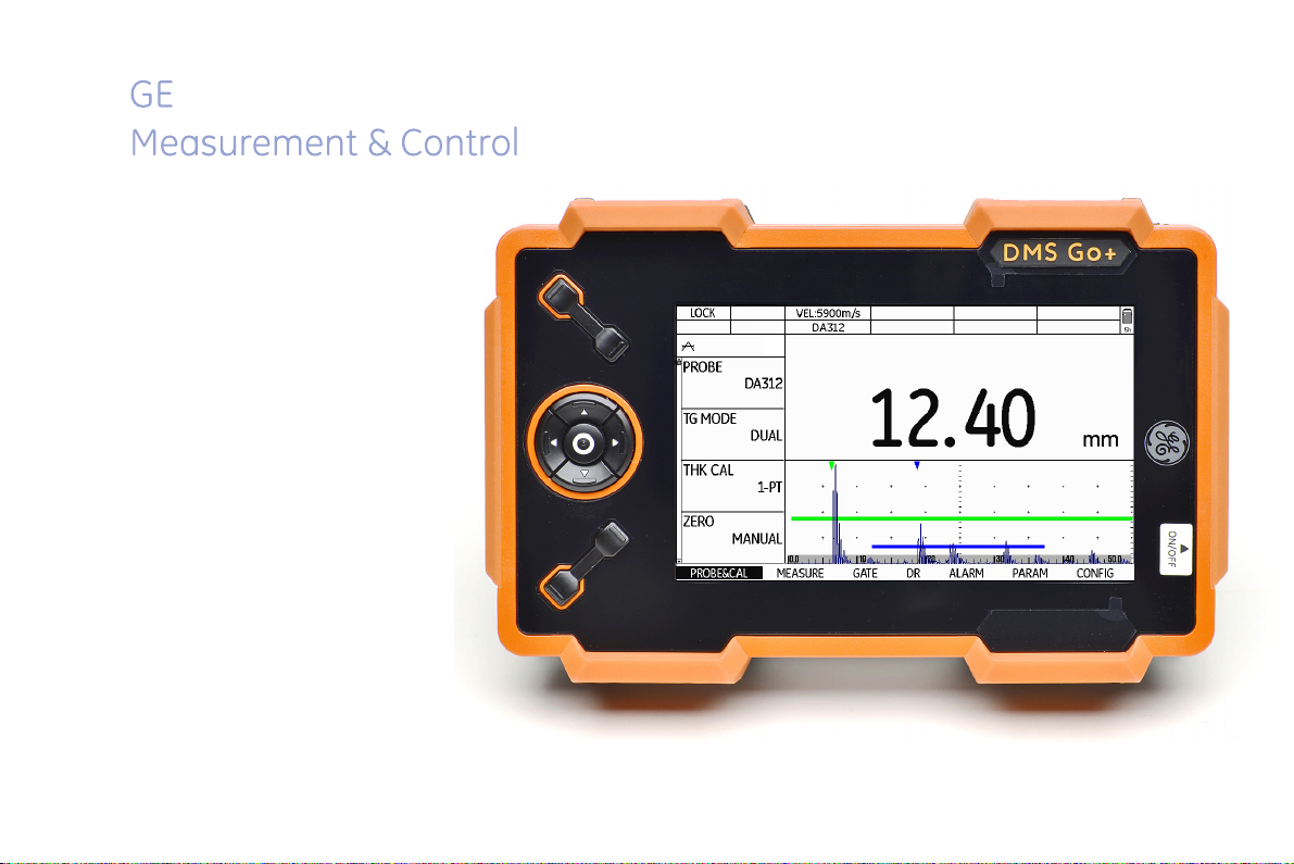
DMS Go+
Technical Reference and Operating Manual
Page 2

This edition 4 (05/2014) applies to the software version 3.20 (April 2, 2014)
You will find the software version and the serial number of your instrument at CONFIG - ABOUT.
© GE Sensing & Inspection Technologies GmbH | Technical content subject to change without notice.
Page 3
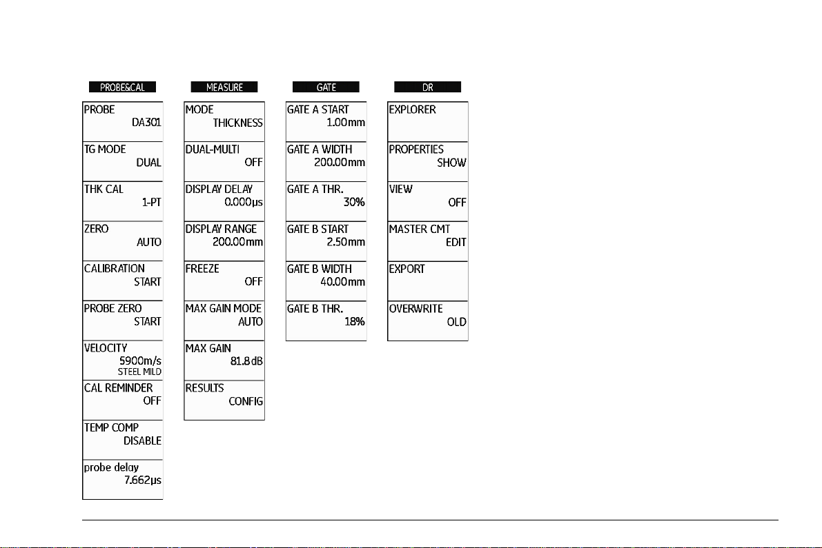
Function groups and functions
DMS Go+ Edition 4 (05/2014) 0-3
Page 4
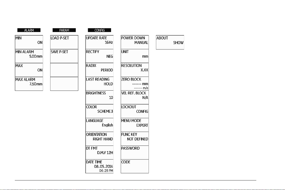
Function groups and functions (cont'd)
0-4 Edition 4 (05/2014) DMS Go+
Page 5
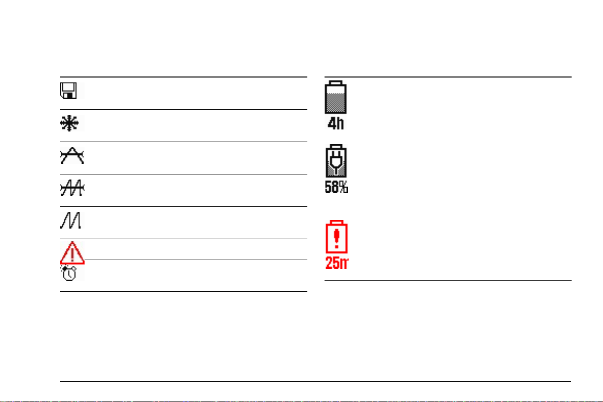
Status display icons Power level indicators
Icon Meaning
SD memory card is inserted,
flashes when the SD card is accessed
Display memory active (Function FREEZE),
display is „frozen“.
Measurement mode S-IP, DUAL
Measurement mode S-PEAK, S-FLANK
Measurement mode DUAL-MULTI
Alarm threshold exceeded or fallen below
Reminder for calibration
Icon Meaning
Battery charge level,
remaining operating time
in hours (approximate value)
Charger/power adapter is connected,
percentage of battery charge level
(approximate value)
Warning: Low battery charge level,
remaining operating time
in minutes (approximate value)
DMS Go+ Edition 4 (05/2014) 0-5
Page 6
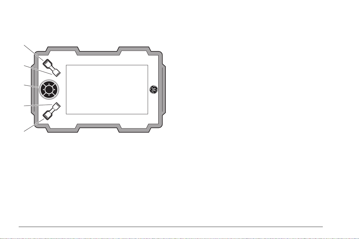
Basic key functions
1
2
3
4
5
1 Function key 1, functions are context-dependent
2 Function key 2, functions are context-dependent; keys 1 and 2 simultaneously: Save screen shot
3 Keypad, navigation between function groups and functions, changing settings
4 Function key 3, functions are context-dependent
5 Function key 4, function individually assignable (CONFIG – FUNC KEY),
0-6 Edition 4 (05/2014) DMS Go+
Page 7
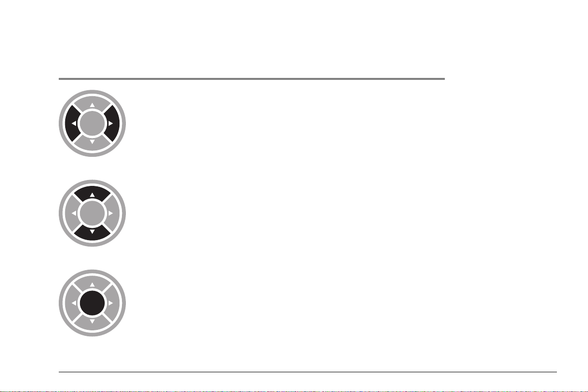
Navigation
Keys Function
Navigation between function groups,
adjusting values
Navigation between functions
within a function group
Changing the display orientation (landscape - portrait)
DMS Go+ Edition 4 (05/2014) 0-7
Page 8

0-8 Edition 4 (05/2014) DMS Go+
Page 9

Contents
0 Overview
Function groups and functions . . . . . . . . . 0-3
Function groups and functions (cont'd). . . 0-4
Status display icons . . . . . . . . . . . . . . . . . 0-5
Power level indicators. . . . . . . . . . . . . . . . 0-5
Basic key functions . . . . . . . . . . . . . . . . . . 0-6
Navigation. . . . . . . . . . . . . . . . . . . . . . . . . 0-7
1 Introduction
1.1 Safety information . . . . . . . . . . . . . . . . . 1-2
Battery operation . . . . . . . . . . . . . . . . . . . 1-2
Software . . . . . . . . . . . . . . . . . . . . . . . . . . 1-2
Defects/errors and exceptional stresses. . 1-3
1.2 Important information on
wall thickness measurement . . . . . . . . . 1-4
Prerequisites for the use of ultrasonic
thickness gauges . . . . . . . . . . . . . . . . . . . 1-4
Limits of ultrasonic testing . . . . . . . . . . . . 1-5
Ultrasonic wall thickness measurement . . 1-5
Effect of the test object material . . . . . . . . 1-6
Effect of temperature variations . . . . . . . . 1-6
Measurement of remaining wall thickness 1-6
Choice of the probe. . . . . . . . . . . . . . . . . . 1-7
Use of couplants . . . . . . . . . . . . . . . . . . . . 1-7
Doubling of measured value . . . . . . . . . . . 1-7
1.3 Important information on wall thickness
measurement using the DMS Go+ . . . . 1-8
Probe zero offset. . . . . . . . . . . . . . . . . . . . 1-8
Measuring accuracy . . . . . . . . . . . . . . . . . 1-8
Probes. . . . . . . . . . . . . . . . . . . . . . . . . . . . 1-9
1.4 The DMS Go+ . . . . . . . . . . . . . . . . . . . . 1-12
Overview of functions . . . . . . . . . . . . . . . 1-12
Options . . . . . . . . . . . . . . . . . . . . . . . . . . 1-14
1.5 Wall thickness measurement
using the DMS Go+. . . . . . . . . . . . . . . . 1-15
Principle of ultrasonic measurement. . . . 1-15
Dual mode (measurement mode DUAL). 1-16
Single-element mode (measurement
modes S-IP, S-PEAK, S-FLANK) . . . . . . 1-17
Multi-echo mode
(measurement mode DUAL-MULTI). . . . 1-17
DMS Go+ Edition 4 (05/2014) 0-1
Page 10

Contents
TopCOAT method
(measurement mode TOP-COAT) . . . . . 1-18
Auto-V (measurement mode AUTO-V). . 1-19
B-scan. . . . . . . . . . . . . . . . . . . . . . . . . . . 1-20
Display orientation . . . . . . . . . . . . . . . . . 1-21
1.6 The USM Go+ . . . . . . . . . . . . . . . . . . . . 1-22
1.7 How to use this manual . . . . . . . . . . . . 1-22
Overview . . . . . . . . . . . . . . . . . . . . . . . . . 1-23
1.8 Layout and presentation in
this manual . . . . . . . . . . . . . . . . . . . . . . 1-24
Attention and note symbols. . . . . . . . . . . 1-24
Listings . . . . . . . . . . . . . . . . . . . . . . . . . . 1-24
Operating steps. . . . . . . . . . . . . . . . . . . . 1-24
2 Standard package and accessories
2.1 Standard package . . . . . . . . . . . . . . . . . . 2-2
2.2 Add-on functions . . . . . . . . . . . . . . . . . . 2-3
2.3 Preconfigured function packages. . . . . 2-4
2.5 Recommended probe cables . . . . . . . . 2-10
2.6 Recommended accessories. . . . . . . . . 2-12
3 Initial start-up
3.1 Instrument positioning . . . . . . . . . . . . . . 3-2
3.2 Power supply. . . . . . . . . . . . . . . . . . . . . . 3-2
Operation with charger/power adapter . . . 3-2
Operation using batteries . . . . . . . . . . . . . 3-4
Charging the batteries. . . . . . . . . . . . . . . . 3-8
3.3 Connecting a probe . . . . . . . . . . . . . . . . 3-9
Dual-type connectors . . . . . . . . . . . . . . . . 3-9
Single-type connectors . . . . . . . . . . . . . . . 3-9
3.4 Inserting the SD memory card . . . . . . . 3-10
3.5 Starting the DMS Go+ . . . . . . . . . . . . . . 3-11
Powering On . . . . . . . . . . . . . . . . . . . . . . 3-11
Powering Off . . . . . . . . . . . . . . . . . . . . . . 3-12
Factory default setting (Reset) . . . . . . . . 3-12
2.4 Recommended probes . . . . . . . . . . . . . . 2-5
0-2 Edition 4 (05/2014) DMS Go+
Page 11

Contents
4 Principles of operation
4.1 Overview of operator's controls . . . . . . 4-2
4.2 Display screen . . . . . . . . . . . . . . . . . . . . 4-3
Display modes . . . . . . . . . . . . . . . . . . . . . 4-3
Functions on the display screen . . . . . . . . 4-5
Icons and information . . . . . . . . . . . . . . . . 4-5
Display of reading . . . . . . . . . . . . . . . . . . . 4-6
4.3 Navigation and function keys . . . . . . . . 4-7
Keypad . . . . . . . . . . . . . . . . . . . . . . . . . . . 4-7
Function keys . . . . . . . . . . . . . . . . . . . . . . 4-7
Power key . . . . . . . . . . . . . . . . . . . . . . . . . 4-7
Key combinations . . . . . . . . . . . . . . . . . . . 4-8
4.4 Operational concept . . . . . . . . . . . . . . . . 4-9
Changing the display views . . . . . . . . . . . 4-9
Selecting and setting functions. . . . . . . . 4-10
5 Operation
5.1 Default settings . . . . . . . . . . . . . . . . . . . . 5-2
Language setting . . . . . . . . . . . . . . . . . . . 5-2
Units setting . . . . . . . . . . . . . . . . . . . . . . . 5-3
Resolution setting . . . . . . . . . . . . . . . . . . . 5-3
Radix. . . . . . . . . . . . . . . . . . . . . . . . . . . . . 5-4
Last reading . . . . . . . . . . . . . . . . . . . . . . . 5-4
Date format, Date, and Time. . . . . . . . . . . 5-5
Selecting the instrument orientation . . . . . 5-6
Display orientation . . . . . . . . . . . . . . . . . . 5-6
Assignment of function key 4 . . . . . . . . . . 5-7
Function lockout . . . . . . . . . . . . . . . . . . . . 5-8
Password protection . . . . . . . . . . . . . . . . 5-10
Power saving mode . . . . . . . . . . . . . . . . 5-12
Configuring data boxes . . . . . . . . . . . . . . 5-13
5.2 Default settings of the display. . . . . . . 5-15
Setting the brightness . . . . . . . . . . . . . . . 5-15
Selecting the color scheme. . . . . . . . . . . 5-16
DMS Go+ Edition 4 (05/2014) 0-3
Page 12

Contents
5.3 Operating modes and views . . . . . . . . 5-17
Changing the operating mode or view . . 5-17
5.4 Saving the settings . . . . . . . . . . . . . . . . 5-18
Loading settings . . . . . . . . . . . . . . . . . . . 5-19
Deleting settings . . . . . . . . . . . . . . . . . . . 5-19
5.5 Preparing for measurements . . . . . . . . 5-20
Choosing the probe type. . . . . . . . . . . . . 5-21
Choosing the measurement mode . . . . . 5-22
5.6 Carrying out the calibration. . . . . . . . . 5-24
Calibrations . . . . . . . . . . . . . . . . . . . . . . . 5-24
Probe zero offset. . . . . . . . . . . . . . . . . . . 5-25
Calibration to zero and to sound velocity 5-27
Setting the sound velocity . . . . . . . . . . . . 5-31
5.7 Carrying out measurements . . . . . . . . 5-32
5.8 A-scan configuration . . . . . . . . . . . . . . 5-33
Setting the display range . . . . . . . . . . . . 5-33
Setting the gain . . . . . . . . . . . . . . . . . . . . 5-34
Selecting the display update rate . . . . . . 5-35
Selecting the rectification mode . . . . . . . 5-36
Setting the probe delay . . . . . . . . . . . . . . 5-36
5.9 Setting the gates . . . . . . . . . . . . . . . . . . 5-37
Task of the gates. . . . . . . . . . . . . . . . . . . 5-37
Gate start . . . . . . . . . . . . . . . . . . . . . . . . 5-37
Gate width . . . . . . . . . . . . . . . . . . . . . . . . 5-38
Gate threshold. . . . . . . . . . . . . . . . . . . . . 5-38
5.10 Configuring alarm functions . . . . . . . . 5-39
Minimum value alarm . . . . . . . . . . . . . . . 5-39
Maximum value alarm . . . . . . . . . . . . . . . 5-39
5.11 MIN/MAX mode . . . . . . . . . . . . . . . . . . . 5-40
Switching the MIN/MAX mode on . . . . . .5-41
Clearing a sequence of measurements . 5-41
5.12 Thickness profiles with the B-scan . . . 5-42
Switching the B-scan display on . . . . . . . 5-43
Setting the display time . . . . . . . . . . . . . . 5-43
Setting the waiting time . . . . . . . . . . . . . . 5-44
Minimum value line . . . . . . . . . . . . . . . . . 5-44
Recording a B-scan. . . . . . . . . . . . . . . . . 5-45
0-4 Edition 4 (05/2014) DMS Go+
Page 13

Contents
5.13 Differential value display . . . . . . . . . . . 5-46
Switching the differential value
display on . . . . . . . . . . . . . . . . . . . . . . . . 5-46
5.14 A-scan view . . . . . . . . . . . . . . . . . . . . . . 5-47
5.15 Other functions . . . . . . . . . . . . . . . . . . . 5-48
Saving calibration block data . . . . . . . . . 5-48
Calibration reminder . . . . . . . . . . . . . . . . 5-50
Temperature compensation . . . . . . . . . . 5-51
Display freeze (FREEZE) . . . . . . . . . . . . 5-52
Gate magnifier (ZOOM) . . . . . . . . . . . . . 5-53
5.16 Enabling options (Upgrade). . . . . . . . . 5-54
6 Data Recorder
6.1 Overview of functions . . . . . . . . . . . . . . 6-2
6.2 File types . . . . . . . . . . . . . . . . . . . . . . . . . 6-4
File type LINEAR . . . . . . . . . . . . . . . . . . . 6-4
File type CUSTOM LINEAR . . . . . . . . . . . 6-5
File type CUSTOM POINT . . . . . . . . . . . . 6-5
File type GRID . . . . . . . . . . . . . . . . . . . . . 6-6
File type CUSTOM GRID . . . . . . . . . . . . . 6-6
File type BOILER . . . . . . . . . . . . . . . . . . . 6-7
6.3 Master comment list . . . . . . . . . . . . . . . . 6-8
Creating a master comment list . . . . . . . . 6-8
Changing master comments . . . . . . . . . . . 6-9
6.4 Working with files . . . . . . . . . . . . . . . . . 6-11
Creating a new file . . . . . . . . . . . . . . . . . 6-11
Deleting files . . . . . . . . . . . . . . . . . . . . . . 6-13
6.5 Saving measurement results. . . . . . . . 6-14
Loading a file. . . . . . . . . . . . . . . . . . . . . . 6-14
Saving readings . . . . . . . . . . . . . . . . . . . 6-15
Special measuring point functions . . . . . 6-16
Selecting individual measuring points. . . 6-16
Clearing a reading. . . . . . . . . . . . . . . . . . 6-17
Overwriting readings . . . . . . . . . . . . . . . . 6-17
Saving readings with A-scans . . . . . . . . . 6-18
Adding comments . . . . . . . . . . . . . . . . . . 6-20
Editing a file comment list . . . . . . . . . . . . 6-22
DMS Go+ Edition 4 (05/2014) 0-5
Page 14

Contents
6.6 Editing files . . . . . . . . . . . . . . . . . . . . . . 6-24
Expanding the file capacity . . . . . . . . . . . 6-24
Deleting parts of a file . . . . . . . . . . . . . . . 6-26
Editing header data. . . . . . . . . . . . . . . . . 6-27
Adding a Microgrid . . . . . . . . . . . . . . . . . 6-29
Automatic advance . . . . . . . . . . . . . . . . . 6-33
6.7 Evaluations . . . . . . . . . . . . . . . . . . . . . . 6-36
Viewing statistical evaluations . . . . . . . . 6-36
Changing the view (Spread – List) . . . . . 6-38
Viewing stored reading attachments. . . . 6-39
6.8 Documenting measurements. . . . . . . . 6-40
Data export . . . . . . . . . . . . . . . . . . . . . . . 6-40
Screen shots . . . . . . . . . . . . . . . . . . . . . . 6-41
7 Special functions of the DMS Go+ TC
7.1 Basics . . . . . . . . . . . . . . . . . . . . . . . . . . . 7-2
7.2 Measurement mode Auto-V . . . . . . . . . . 7-6
Applications. . . . . . . . . . . . . . . . . . . . . . . . 7-6
Choosing the probe. . . . . . . . . . . . . . . . . . 7-6
Activating Auto-V. . . . . . . . . . . . . . . . . . . . 7-6
Zeroing for Auto-V. . . . . . . . . . . . . . . . . . . 7-7
Checking reference block data . . . . . . . . . 7-7
7.3 Measurement mode TopCOAT. . . . . . . . 7-9
Applications. . . . . . . . . . . . . . . . . . . . . . . . 7-9
Choosing the probe. . . . . . . . . . . . . . . . . . 7-9
Activating TopCOAT . . . . . . . . . . . . . . . . . 7-9
Zeroing for TopCOAT . . . . . . . . . . . . . . . 7-10
Checking reference block data . . . . . . . . 7-10
Sound velocity in the test object.. . . . . . . 7-11
Calibration to the sound velocity . . . . . . . 7-12
Sound velocity in the coating . . . . . . . . . 7-13
8 Maintenance and care
8.1 Instrument care . . . . . . . . . . . . . . . . . . . . 8-2
8.2 Battery care . . . . . . . . . . . . . . . . . . . . . . . 8-2
Battery care. . . . . . . . . . . . . . . . . . . . . . . . 8-2
Charging the batteries. . . . . . . . . . . . . . . . 8-3
8.3 Maintenance . . . . . . . . . . . . . . . . . . . . . . 8-3
0-6 Edition 4 (05/2014) DMS Go+
Page 15

Contents
8.4 Software updates . . . . . . . . . . . . . . . . . . 8-4
Download of update files . . . . . . . . . . . . . 8-4
Installing an update. . . . . . . . . . . . . . . . . . 8-5
9 Interfaces and Peripherals
9.1 Interfaces. . . . . . . . . . . . . . . . . . . . . . . . . 9-2
Overview. . . . . . . . . . . . . . . . . . . . . . . . . . 9-2
USB interface . . . . . . . . . . . . . . . . . . . . . . 9-3
Service interface (Mini RS232-C) . . . . . . . 9-3
9.2 Peripherals . . . . . . . . . . . . . . . . . . . . . . . 9-4
10 Appendix
10.1 Application notes . . . . . . . . . . . . . . . . . 10-2
General notes . . . . . . . . . . . . . . . . . . . . . 10-2
10.2 Sound velocities . . . . . . . . . . . . . . . . . . 10-4
10.3 Data Recorder file types. . . . . . . . . . . . 10-7
File type LINEAR . . . . . . . . . . . . . . . . . . 10-7
File type GRID . . . . . . . . . . . . . . . . . . . . 10-9
File type CUSTOM LINEAR . . . . . . . . . 10-11
File type CUSTOM GRID . . . . . . . . . . . 10-13
File type CUSTOM POINT . . . . . . . . . . 10-15
File type BOILER . . . . . . . . . . . . . . . . . 10-17
10.4 Flag symbols . . . . . . . . . . . . . . . . . . . . 10-19
10.5 Function directory . . . . . . . . . . . . . . . 10-20
10.6 EU Declaration of Conformity . . . . . . 10-25
10.7 Manufacturer/Service addresses. . . . 10-25
10.8 Environmental protection
regulations. . . . . . . . . . . . . . . . . . . . . . 10-27
WEEE directive (Waste Electrical
and Electronic Equipment) . . . . . . . . . . 10-27
Disposal of batteries . . . . . . . . . . . . . . . 10-28
10.9 Recycling directives . . . . . . . . . . . . . . 10-30
Overview . . . . . . . . . . . . . . . . . . . . . . . . 10-30
Materials to be disposed of separately . 10-33
Other materials and components . . . . . 10-36
Recycling data of the DMS Go+ . . . . . . 10-43
DMS Go+ Edition 4 (05/2014) 0-7
Page 16

11 Specifications
11.1 Specifications of the DMS Go+ . . . . . . 11-2
Display screen . . . . . . . . . . . . . . . . . . . . 11-2
Display . . . . . . . . . . . . . . . . . . . . . . . . . . 11-3
Connectors . . . . . . . . . . . . . . . . . . . . . . . 11-4
Pulser . . . . . . . . . . . . . . . . . . . . . . . . . . . 11-4
Receiver . . . . . . . . . . . . . . . . . . . . . . . . . 11-5
Memory . . . . . . . . . . . . . . . . . . . . . . . . . . 11-5
Environment . . . . . . . . . . . . . . . . . . . . . . 11-6
Protection . . . . . . . . . . . . . . . . . . . . . . . . 11-7
Options . . . . . . . . . . . . . . . . . . . . . . . . . . 11-8
11.2 Specifications according to
EN 12668 . . . . . . . . . . . . . . . . . . . . . . . . 11-9
12 Index
0-8 Edition 4 (05/2014) DMS Go+
Page 17

Introduction 1
DMS Go+ Edition 4 (05/2014) 1-1
Page 18

1 Introduction Safety information
ATTENTION
1.1 Safety information
The DMS Go+ has been designed and tested according
to DIN
EN 61010-1: 2011-07, Safety requirements for
electrical equipment for measurement, control and lab
oratory use, and was technically in perfectly safe and
faultless condition when leaving the manufacturing
works.
In order to maintain this condition and to ensure a safe
operation, you should always read the following safety
information carefully before putting the instrument into
operation.
The DMS Go+ is an instrument for materials testing. Any use for medical or any
other applications is not permitted!
The instrument may only be used in industrial environments.
The DMS Go+ is waterproof according to IP67. It can be
operated either with the corresponding lithium-ion bat
teries or with the charger/power adapter. The charger/
power adapter meets the requirements of electrical
safety class II.
-
Battery operation
For the battery operation of the DMS Go+, we recommend the corresponding lithium-ion battery. You should
only use this battery for the battery operation.
You can charge the lithium-ion battery either within the
instrument itself or in an external charger. If a lithium-ion
battery is inserted, charging starts automatically as
soon as you connect the charger/power adapter to the
DMS Go+ and to the mains power supply.
For power supply, please also see Chapter 3.2 Power
supply, page 3-2. For the use of batteries, please also
see Chapter 8.2 Battery care, page 8-2.
Software
According to the current state of the art, software is never completely free from errors. Before using any software-controlled test equipment, it is therefore necessary to make sure that the required functions operate
perfectly in the intended combination.
If you have any questions about the use of your test
equipment, please contact your nearest representative
of GE.
1-2 Edition 4 (05/2014) DMS Go+
Page 19

Safety information 1 Introduction
Defects/errors and exceptional stresses
If you have reason to believe that a safe operation of
your DMS Go+ is no longer possible, you have to dis
connect the instrument and secure it against unintentional reconnection. Remove the lithium-ion battery.
A safe operation is no longer possible for example
● if the instrument shows visible damages,
● if the instrument no longer operates perfectly,
● after prolonged storage under adverse conditions
(e.g. exceptional temperatures or especially high air
humidity, or corrosive environmental conditions),
● after being subjected to heavy stresses during transportation.
-
DMS Go+ Edition 4 (05/2014) 1-3
Page 20

1 Introduction Important information on wall thickness measurement
ATTENTION
1.2 Important information on wall thickness measurement
Please read the following information before
using your thickness gauge. It is very import
ant that you understand and observe this information to avoid any errors when using the
instrument that might lead to false measure
ment results. Decisions made on the basis of
false measurement results may lead to prop
erty damages and personal injuries.
Prerequisites for the use of ultrasonic thickness gauges
This operating manual contains essential information on
how to operate your thickness gauge. In addition, there
are a number of factors that affect the measurement re
sults. A description of all these factors would go beyond
the scope of an operating manual. Therefore, only the
most important prerequisites for a safe and reliable ul
trasonic thickness measurement are mentioned here:
-
● Training of the instrument operator (operator)
● Knowledge of special technical measurement re-
quirements and limits
● Choice of the appropriate measuring device
The operation of an ultrasonic measuring device requires proper training in ultrasonic thickness measure-
ment. Proper training comprises for example adequate
knowledge of the following:
● Theory of the propagation of sound waves in materi-
-
als
-
● Effects of the sound velocity of test material
● Behavior of sound waves at interfaces between dif-
ferent materials
● Propagation of the sound beam within the material
● Effect of the surface quality of test material.
-
1-4 Edition 4 (05/2014) DMS Go+
Page 21

Important information on wall thickness measurement 1 Introduction
Lack of such knowledge could lead to false measurement results with unforeseeable consequences. Information about the existing training opportunities for ultrasonic inspectors and about the qualifications and certificates that can finally be obtained is available at the
national NDT societies or at GE.
GE holds specialized training courses in the field of ultrasonic testing at regular intervals. The scheduled
dates for these courses will be given to you on request.
Limits of ultrasonic testing
The information obtained from ultrasonic tests only refers to those parts of the test object which are covered
by the sound beam of the probe used. Should any con
clusions from the tested parts be applied to the untested
parts of the test object, they should therefore be made
with extreme caution. Such conclusions are generally
only possible in cases where extensive experience of
the components to be tested and proven methods of
statistical data acquisition are available.
Boundary surfaces within the test object can completely
reflect the sound beam, resulting in reflection points
which lie beyond this, for example the component's
backwall, remaining undetected. It is therefore import
ant to make sure that all areas to be tested in the test
object are covered by the sound beam.
Ultrasonic wall thickness measurement
All ultrasonic wall thickness measurements are based
on a time-of-flight measurement of the sound pulse in
the test object. Accurate measurement results therefore
require a constant sound velocity in the test object. This
requirement is generally met in test objects made of
steel, even with different alloying constituents. The vari
ation of sound velocity is so slight that it is only of impor-
tance for high-precision measurements. In other materials, for example nonferrous metals or plastics, the
sound velocity is nevertheless subject to larger varia
tions. These may affect the measuring accuracy.
-
-
-
DMS Go+ Edition 4 (05/2014) 1-5
Page 22

1 Introduction Important information on wall thickness measurement
Effect of the test object material
If the material is not homogeneous, the sound waves
may propagate at different velocities in different parts of
the test object. In this case, an average sound velocity
should therefore be taken into account for the instru
ment calibration.
However, the best results are obtained when the instrument is calibrated using a reference block made of the
same material as the test object. This calibration block
should have plane-parallel surfaces and a thickness
corresponding to the maximum thickness of the test ob
ject. The operator
should additionally keep in mind that the sound velocity
is liable to vary substantially due to heat treatments.
This fact must be taken into account when assessing
the accuracy of the wall thickness measured by the in
strument.
If substantial sound velocity variations are expected,
then the instrument calibration should be adjusted to the
actual sound velocity values at shorter time intervals.
Failure to do so may lead to false thickness readings.
-
Effect of temperature variations
The sound velocity within the test object also varies
along with material's temperature. This can cause ap
preciable errors in measurements if the instrument has
been calibrated on a cold reference block, whereas the
thickness measurement is carried out on a warm test
object. Such measurement errors can be avoided either
by adjusting the temperature of the reference block
used for calibration or by taking the temperature effect
on the sound velocity into consideration on the basis of
a correction factor obtained from published tables.
-
Measurement of remaining wall thickness
The measurement of the remaining wall thickness on
plant components, e.g. pipes, tanks, or reaction vessels
of all types which are corroded or eroded from the in
side, requires a perfectly suitable gauge and special
care in handling the probe.
The operator should always be informed about the corresponding nominal wall thicknesses as well as about
the likely amount of wall thickness losses.
-
-
1-6 Edition 4 (05/2014) DMS Go+
Page 23

Important information on wall thickness measurement 1 Introduction
Choice of the probe
The probe used for the measurement must be in good
condition, i.e. its coupling face or delay line should not
show any considerable wear. The measuring range (ap
plication range) specified for the corresponding probe in
the data sheets must cover the complete thickness
range to be inspected. The temperature of the test ob
ject must be within the permissible temperature range of
the selected probe.
Use of couplants
The operator must be familiar with the use of the ultrasonic couplant to the effect that the couplant is applied
equally during every measurement so that variations in
the couplant layer thickness and errors in the subse
quent measurement results are avoided. The instrument calibration and the actual wall thickness measurement should be carried out under identical coupling conditions. During this process, the quantities of couplant
used should be as small as possible and a constant
pressure should be applied to the probe.
-
In the case of curved coupling faces, for example on
tubes, the dual-element probe used for the measure
ment should be coupled in such a way that its acoustic
separation layer forms an angle of 90° with reference to
-
the tube's longitudinal axis.
Doubling of measured value
-
A dangerous measuring error in ultrasonic thickness
measurement can occur if the thickness is measured
below the application range (operating range) specified
for the probe used. In this case, the first backwall echo
is too small for an evaluation, whereas the second back
wall echo has an adequately high amplitude and is
therefore evaluated by the instrument. This results in a
wall thickness reading which is twice as large as the ac
tual wall thickness. In order to avoid such measuring errors, the operator must carry out an additional check
measurement using another probe at the limit of the ap
plication range.
-
-
-
-
DMS Go+ Edition 4 (05/2014) 1-7
Page 24

1 Introduction Important information on wall thickness measurement using the DMS Go+
ATTENTION
1.3 Important information on wall thickness measurement using the DMS Go+
Please always read the following information
about the special features in wall thickness
measurement using the DMS Go+. It is abso
lutely necessary that you observe this information in order to always obtain correct
measurement results.
Probe zero offset
High differences in temperature
If the differences in temperature between the storage
and inspection site are high, it is necessary that you wait
approx. 2 minutes before you use the instrument after
connecting the probe.
at temperatures below –10 °C. You should therefore
carry out a 2-point calibration and repeat it in the case
of major temperature jumps.
Couplant residues
In order to ensure a correct probe zero offset, make sure
that you always remove the couplant residues before
carrying out a new measurement after decoupling the
probe.
-
Measuring accuracy
Keep in mind that the measuring accuracy is not identical with the display accuracy.
The measuring accuracy depends on the following factors:
● Temperature
● Probe delay line
● Constancy of sound velocity
● Uniformity of surface quality
Temperatures below –10 °C
The probe zero offset does not always function correctly
1-8 Edition 4 (05/2014) DMS Go+
Page 25

Important information on wall thickness measurement using the DMS Go+ 1 Introduction
Probes
Please note that only probes specified in chapter 2 of
this manual are accepted for the DMS Go+.
V-path correction
The following probes have only one transducer element
and therefore require no V-path correction:
● K 1 SC ● K-PEN ● G5 KB
● G 2 N ● CLF 5 ● CLF 4
● CA 215 ● CA 214 ● CA 211
● CA 211 A ● A DFRP ● A2 DFR
● A2 DFR ● A2 10 M ● 5 M 5 DFR
All probes equipped with a transmitter and a receiver element require a V-path correction due to the inclined position of their transducer elements (with wall thicknesses < 60 mm in steel).
The V-path correction is stored in the DMS Go+ for the
following probes:
● Alpha2 D ● CA 211A ● DA 301
● DA 303 ● DA 312 ● DA 312 B1
● DA 501 EN ● DA 503 EN ● DA 507
● DA 512 ● D 590 ● FH 2 E
● HT 400 A ● KBA 525 ● KBA 560
● OSS 10 ● TC 560 ● D 790
DMS Go+ Edition 4 (05/2014) 1-9
Page 26

1 Introduction Important information on wall thickness measurement using the DMS Go+
The following probes have been corrected individually
during the manufacturing process; the V-path correction
is stored in the probe. For some of these probes
(marked with *), this was additionally done for the oper
ating mode DUAL-MULTI.
● DA 401 ● DA 403 ● DA 408
● DA 411 ● DA 412* ● DA 451*
● DA 453 ● DA 458 ● DA 461*
● DA 462* ● DA 455 ● DA 465
● DA 467 ● DA 469 ● FH 2 ED REM
Zeroing
The correct zeroing is important for the measuring accuracy of probes equipped with a transmitter and a receiver element. A difference is made between two methods:
1 Zeroing before coupling the probe
(OFF-BLOCK zeroing)
2 Zeroing during probe coupling
(ON-BLOCK zeroing)
Zeroing before coupling the probe (OFF-BLOCK
zeroing)
After powering the DMS Go+ on, the length of the delay
line below the transmitter element is determined at reg
ular intervals whenever the probe is not coupled for the
wall thickness measurement. In this regard, it is import
ant that the coupling face of the probe is free from couplant to a large extent in order to avoid any faulty measurements.
This method is of advantage in cases where rough or
curved surfaces may result in a critical coupling. When
determining wall thicknesses in plastics, only probes
with zeroing before coupling should be chosen:
● DA 401 ● DA 403 ● DA 408
● DA 411 ● DA 412 ● D 790
● FH 2 E ● KBA 525 ● KBA 560
● HT 400 A ● TC 560
-
-
1-10 Edition 4 (05/2014) DMS Go+
Page 27

Important information on wall thickness measurement using the DMS Go+ 1 Introduction
Zeroing during probe coupling (ON-BLOCK zeroing)
After coupling the probe (but before each individual wall
thickness measurement), the length of the delay line be
low the transmitter element is determined at first. The
actual wall thickness measurement is not carried out till
after that.
This method is of advantage whenever a high stability
and reproducibility of the measured values are required.
For example, if the temperature of the part to be tested
differs largely from that of the probe, the delay lines are
cooled down during coupling and thus reduced, or they
are heated up and thus extended. Each zero drift is thus
compensated for immediately before every wall thick
-
ness measurement in the case of these probes:
● DA 301 ● DA 303 ● DA 305
● DA 312 ● DA 312 B... ● DA 315
● DA 317 ● DA 319 ● DA 451*
● DA 453* ● DA 461* ● DA 462*
● DA 465* ● DA 467* ● DA 469*
In the case of probes marked with *, the zero is determined as an arithmetic mean of the two probe delay
lines. For example, probes showing beveled wear can
thus comply with their original measured-value toler
ance better.
-
DMS Go+ Edition 4 (05/2014) 1-11
Page 28
1 Introduction The DMS Go+
1.4 The DMS Go+
Overview of functions
The DMS Go+ is a portable thickness gauge with an integrated data recorder You can use this instrument for
measuring the wall thickness on a large variety of com
ponents, for example on tubes, pressure vessels, and
other equipment parts whose wall thickness is subject to
a gradual reduction.
This makes the DMS Go+ especially suitable for measurement tasks for the documented corrosion test.
Special features of the DMS Go+
● high measuring stability and reliability thanks to the
zero crossing method
● automatic gain control for an improved reproducibility
during corrosion tests
● dust-tight and waterproof housing according to IP67
-
● low weight (845 g incl. batteries)
● long operating time (8 hours) due to lithium-ion bat-
tery with internal and external charging possibility
● one-handed operation is possible
● high-resolution color screen (800 x 480 pixels) for the
display of measured values and A-scan
● enlarged display of measured values which are easy
to read even from a greater distance
● color-coded display of gates for easy differentiation
1-12 Edition 4 (05/2014) DMS Go+
Page 29

The DMS Go+ 1 Introduction
● high memory capacity with 2GB SD card. SD cards
with a memory capacity up to 16
GB can be used.
● measuring range 0.25 … 14000 mm (steel), depending on the probe, material, and surface
● digital resolution 0.01 mm or 0.1 mm (selectable)
over the entire measuring range
● units selectable between inch and mm
● integrated data recorder for 100,000 measurements
per file. Several files can be saved to the SD card.
● up to 16 user-definable comments for every file format with up to 16 alphanumeric characters per measuring point
● automatic probe detection with dialog probes, optimized setup and power of the instrument, especially
higher measuring accuracy thanks to the individual Vpath correction data stored in the corresponding
probe used
● MicroGrid function for testing the direct surroundings
of the measuring point
● single-element operating mode with measurement at
echo flank or echo peak
● MIN operating mode with increased pulse repetition
frequency for detecting the smallest reading in a se
ries of measurements
● Dual-Multi operating mode for measuring through
coatings
● adjustable minimum and maximum limits with alarm
signaling through color change of the reading
● locking function to prevent unintentional changes to
the adjustment values
-
DMS Go+ Edition 4 (05/2014) 1-13
Page 30

Options
Various options extend the basic functions of the DMS
Go+ and can be enabled by a code in each case.
DMS Go+ Base
● Basic version, for universal
ultrasonic wall thickness measurement
DMS Go+ TC
● TopCOAT technology for the simultaneous measurement of coating thickness and metal thickness
● Auto-V function for the wall thickness measurement
of components with unknown sound velocity, without
calibration block during the measurement
DMS Go+ DR
● Extended data recorder
DMS Go+ Advanced
● TopCOAT technology for the simultaneous measurement of coating thickness and metal thickness
● Auto-V function for the wall thickness measurement
of components with unknown sound velocity, without
calibration block during the measurement
● Extended data recorder
1-14 Edition 4 (05/2014) DMS Go+
Page 31

Wall thickness measurement using the DMS Go+ 1 Introduction
1.5 Wall thickness measurement using the DMS Go+
Principle of ultrasonic measurement
At first, the DMS Go+ generates an electric initial pulse
which is guided to the transmitter element of the probe.
Once there, it is converted into a mechanical ultrasonic
pulse. By means of a couplant, the ultrasonic pulse is
transmitted from the probe to the material to be tested
which it passes through at a velocity typical of the mate
rial (sound velocity of the material) until it encounters a
change in the material. Part of the pulse energy is re
flected from there and sent back to the probe (echo). If
the signal reaches the backwall of the test object before
that, the reflected pulse is called backwall echo.
A probe can have one (single-element probe) or several
transducer elements (dual-element probe).
Dual-element probes are especially suitable in the case
of:
-
-
● flaws reaching close to the sound entry surface, i.e.
especially in the case of
● deep-level corrosion and erosion.
DMS Go+ Edition 4 (05/2014) 1-15
Page 32

1 Introduction Wall thickness measurement using the DMS Go+
dual-element probe
backwall
test object
transmitter element
transmitted pulse reflected pulse
receiver element
Dual mode (measurement mode DUAL)
In the dual mode, the tasks of transmitting (T) and receiving (R) are solved by two transducer elements arranged in such a way that they are mechanically separated from each other. An initial pulse is triggered on the
transmitter side and transmitted to the test object. The
echoes are received on the receiver side and reconvert
ed into (very weak) electric pulses.
The DMS Go+ measures the time between transmitting
and receiving the sound pulse (time of flight). The DMS
Go+ determines the material thickness on the basis of
the measured time and the material's sound velocity.
The operating principle of a dual-element probe is
shown in the following figure.
-
1-16 Edition 4 (05/2014) DMS Go+
Page 33

Wall thickness measurement using the DMS Go+ 1 Introduction
probe
2nd backwall echo
boundary surface
between
coating and
1st backwall echo
coating
test object
Single-element mode (measurement modes S-IP, S-PEAK, S-FLANK)
A single-element probe is used for transmitting and receiving the echoes in the single-element mode. For the
wall thickness measurement, the DMS Go+ determines
the time of flight between the entry echo and the first
echo exceeding the gate A. The entry echo (interface
echo) is generated at the transition of the initial pulse
from the probe to the test object.
Multi-echo mode (measurement mode DUAL-MULTI)
The multi-echo mode is recommended, for example, for
the wall thickness measurement of coated test objects.
In this mode, two (or several) backwall echoes are used
for determining the wall thickness. The multi-echo mode
is possible using dual-element probes.
As before, an initial pulse is transmitted by a transducer
element to the test material. In the multi-echo mode,
however, part of the sound pulse energy is reflected
from the boundary surface between the coating (paint
coating) and the test material.
The rest of the energy of the first pulse transmitted passes further through the test material and returns as a
backwall echo.
The time of flight between the two successive backwall
echoes is used, together with the material's sound ve
locity, for determining the material thickness. The
echoes from the coating are ignored in this process.
The operating principle of the multi-echo mode is shown
in the following figure.
DMS Go+ Edition 4 (05/2014) 1-17
Page 34

1 Introduction Wall thickness measurement using the DMS Go+
probe
test object
coating
TopCOAT method (measurement mode TOP-COAT)
The patented TopCOAT method optimizes the corrosion measurement through paint coatings. In this process, the test object and paint coating are measured at
one go, and the two values are displayed on the screen.
Measurements using this method are even possible on
heavily corroded backwalls.
A special probe equipped with two pairs of transmitter/
receiver elements is used for the TopCOAT method.
The first pair of transmitter/receiver elements determines the coating thickness by means of a longitudinal
sound wave propagating beneath the surface of the test
object. At the same time, the second pair determines the
total wall thickness and reduces this value by the coat
ing thickness. The two values are displayed simultaneously on the DMS Go+ screen.
Measurements according to the TopCOAT method are
only possible using the DMS Go+ TC.
The following figure shows the operating principle of the
TopCOAT method using a special probe.
-
1-18 Edition 4 (05/2014) DMS Go+
Page 35

Wall thickness measurement using the DMS Go+ 1 Introduction
probe
test object
Auto-V (measurement mode AUTO-V)
The function Auto-V enables to measure the wall thickness of uncoated test objects without knowing the material's sound velocity. In this function, the sound velocity is determined simultaneously with the wall thickness
measurement. Uncoated materials can thus be mea
sured without an additional calibration and without the
use of reference blocks.
The function Auto-V also uses the probe described with
two pairs of transmitter/receiver elements. One pair of
transmitter/receiver elements calculates the material's
sound velocity by means of a longitudinal sound wave
propagating beneath the surface of the test object and
by means of the known sound path (distance between
transmitter and receiver). At the same time, the second
pair determines the time of flight of the sound pulse in
the test object and uses this value and the material'
sound velocity determined by the first pair to calculate
the wall thickness.
In this way, variations in the sound velocity due to temperature variations or local inhomogeneities within the
material are also included in the wall thickness calcula
tion.
-
The function Auto-V is only available in the version DMS
Go+ TC.
-
DMS Go+ Edition 4 (05/2014) 1-19
Page 36

1 Introduction Wall thickness measurement using the DMS Go+
B-scan
The B-scan is a special, path-dependent representation
of the test object's wall thickness. This representation is
ideal for the display of corroded sections. The probe is
guided over the section to be tested of the component
for this representation.
The cross section of the test object shown in the display
of DMS Go+ gives the operator a quick overview of the
thickness distribution on the component. In this regard,
the minimum wall thicknesses become especially well
visible. The following display shows a typical
B-scan in the display of DMS Go+.
1-20 Edition 4 (05/2014) DMS Go+
Page 37

Wall thickness measurement using the DMS Go+ 1 Introduction
Display orientation
You can change the screen display of DMS Go+ from
landscape to portrait mode (
see Section Display orien-
tation, page 5-6).
In addition, you can toggle between right-hand and lefthand operation (
see Section Selecting the instrument
orientation, page 5-6).
Display orientation in landscape mode
Display orientation in portrait mode
DMS Go+ Edition 4 (05/2014) 1-21
Page 38

1 Introduction The USM Go+
1.6 The USM Go+
The DMS Go+ uses the same operating principle as the
portable flaw detector USM Go+.
Your DMS Go+ can use all functions of the flaw detector
USM Go+ by means of a simple software upgrade. You
will then have two instruments available in one housing.
When you power the instrument on, you can choose the
instrument that you want to use (
ing the DMS Go+, page 3-11).
A separate operating manual is available for the USM
Go+. The functions of the USM Go+ are therefore not
described in the operating manual of the DMS Go+.
see Chapter 3.5 Start-
1.7 How to use this manual
This operating manual applies to all instrument versions
of the DMS Go+. Any differences in the functions or ad
justment values are marked in each case.
Before operating the instrument for the first time, it is absolutely necessary that you read the chapters 1, 3,
and
4. They will inform you about the necessary preparations of the instrument, give you a description of all
keys and displays, and explain the operating principle.
In doing this, you will avoid any errors or failures of the
instrument and be able to use the full range of instru
ment functions.
You will find the specifications of the instrument in
Chapter 11 Specifications.
-
-
1-22 Edition 4 (05/2014) DMS Go+
Page 39

How to use this manual 1 Introduction
Overview
The operation of the DMS Go+ is easy and quick to
learn. To be able to use the instrument quickly, you
should make yourself familiar with its preparation for
use and its basic functions. Please read the following
chapter carefully for this purpose:
Chapter 3 Initial start-up
This is where you'll find all the preparatory measures required for using the instrument.
Chapter 4 Principles of operation
gives you an overview of the operating principle of the
instrument and of the basic operating steps.
Chapter 5 Operation
shows you the settings that you can define and the operating steps needed for the measurement. It shows the
further options and functions presented by the DMS
Go+.
Chapter 6 Data Recorder
This chapter describes the functions and options for using the data recorder, as well as the documentation of
the measurement results.
Chapter 7 Special functions of the DMS Go+ TC
This chapter describes the options Auto-V and
TopCOAT.
Chapter 10 Appendix
You can find additional information about special measurements, the data recorder files types, a function reference, and tables with typical sound velocities in the
Annex.
DMS Go+ Edition 4 (05/2014) 1-23
Page 40

1 Introduction Layout and presentation in this manual
ATTENTION
Note
1.8 Layout and presentation in this manual
To make it easier for you to use this manual, all operating steps, listings, and special notes are always presented in the same way. This will help you find individual
pieces of information quickly.
Attention and note symbols
The ATTENTION symbol indicates peculiarities and special aspects in the operation
which could affect the accuracy of the re
sults.
Note contains e.g. references to other chapters or special recommendations for a function.
-
Listings
Listings are presented in the following form:
● Variant A
● Variant B
● ...
Operating steps
Operating steps appear as shown in the following example:
– Loosen the two screws at the bottom.
– Remove the cover.
–…
1-24 Edition 4 (05/2014) DMS Go+
Page 41

Standard package and accessories 2
DMS Go+ Edition 4 (05/2014) 2-1
Page 42

2 Standard package and accessories Standard package
2.1 Standard package
Product code Description Order number
Thickness gauge DMS Go+
TC-096 Transport case 109 709
LI-138 Lithium-ion battery, 7.4 V, 3.9 Ah, rechargeable 109 707
LiBC-139 AC power adapter/charger, 100V … 260V AC 109 708
SD memory card 8 GB
Display screen protector foils (10 pieces)
WS-342 Safety hand strap 109 753
Quick Start Guide
Operating manual on CD
Manufacturer's certificate
2-2 Edition 4 (05/2014) DMS Go+
Page 43

Add-on functions 2 Standard package and accessories
2.2 Add-on functions
Product code Description Order number
TC TopCOAT and Auto-V
DR Extended Data Recorder
DMS Go+ Edition 4 (05/2014) 2-3
Page 44

2 Standard package and accessories Preconfigured function packages
2.3 Preconfigured function packages
Product code Description Order number
Base Thickness gauge DMS Go+ or DMS Go+
TC Base with TopCOAT and Auto-V
DR Base with Extended Data Recorder
Advanced Base with TopCOAT, Auto-V, and Extended Data Recorder
2-4 Edition 4 (05/2014) DMS Go+
Page 45

Recommended probes 2 Standard package and accessories
2.4 Recommended probes
Product code Description Order number
Probes for corrosion measurements
(one-sided zeroing during coupling):
DA 301 5 MHz, measuring range 1.2 … approx. 200 mm 56 904
DA 303 2 MHz, measuring range 5 … approx. 300 mm 56 905
DA 0.8 G 800 kHz, measuring range 7 … approx. 60 mm 66 501
DA 312 10 MHz, measuring range 0.6 … approx. 50 mm 56 906
DMS Go+ Edition 4 (05/2014) 2-5
Page 46

2 Standard package and accessories Recommended probes
Product code Description Order number
Dialog probes for corrosion measurements
(one-sided zeroing before coupling):
DA 401 5 MHz, measuring range 1.2 … approx. 200 mm 58 637
DA 403 2 MHz, measuring range 5 … approx. 300 mm 58 639
DA 408 800 kHz, measuring range 7 … approx. 60 mm 58 644
DA 411 as DA 401, connectors at the top 58 857
DA 412 10 MHz, measuring range 0.6 … approx. 50 mm 58 638
2-6 Edition 4 (05/2014) DMS Go+
Page 47

Recommended probes 2 Standard package and accessories
Product code Description Order number
Probes for high-temperature measurements
DA 315 2 MHz, measuring range 5 … 150 mm, up to +200 °C 57 167
DA 317 5 MHz, measuring range 2 … 80 mm, up to +200 °C 57 168
DA 319 10 MHz, measuring range 1 … 15 mm, up to +200 °C 57 169
DA 305 High-temperature probe, 5 MHz
56 911
measuring range approx. 4 … 60 mm, up to +600 °C
HT 400 A High-temperature probe,
113-224-760
measuring range 0.5 … approx. 300 mm, up to +540 °C
DMS Go+ Edition 4 (05/2014) 2-7
Page 48

2 Standard package and accessories Recommended probes
Product code Description Order number
Probes for special test tasks:
DA 312 B16 10 MHz, measuring range 0.6 … approx. 12 mm, dia. 3 mm 66 934
KBA 525 10 MHz, measuring range 0.6 … approx. 20 mm, dia. 5 mm 113-516-002
FH2ED-REM Dialog probe, 8 MHz,
113-552-009
measuring range 0.75 … approx. 50 mm, remote control key
TC-560 5 MHz, measuring range 2 … approx. 200 mm
113-544-214
for TopCOAT operating mode (only DMS Go+ TC)
2-8 Edition 4 (05/2014) DMS Go+
Page 49

Recommended probes 2 Standard package and accessories
Product code Description Order number
Probes for precision measurements in
single-element mode (DMS Go+ and DMS Go+ TC):
CLF 4 Delay probe, 15 MHz, measuring range 0.25 … approx. 25 mm 113-527-665
CLF 5 Contact probe, 10 MHz, measuring range 1 … approx. 50 mm 113-526-005
CA 211 A Contact probe, 5 MHz, measuring range 2 … approx. 380 mm 113-544-000
CA 214 5 MHz, only in connection with N 12,5 K delay line 65 121
N 12,5 K Delay line for CA 214 66 382
G5KB Contact probe, 5 MHz, measuring range 2 … approx. 635 mm 58 504
G2N Contact probe, 2 MHz, measuring range 3 … approx. 635 mm 58 501
K1SC Contact probe, 1 MHz, measuring range 5 … approx. 635 mm 59 074
DMS Go+ Edition 4 (05/2014) 2-9
Page 50

2 Standard package and accessories Recommended probe cables
2.5 Recommended probe cables
Product code Description Order number
DA 231 1.5 m (for DA 401, DA 403, DA 408) 53 616
DA 233 1.5 m (for DA 315, DA 317, DA 319, DA 411) 54 999
DA 235 1.5 m (for DA 305, DA 412) 54 374
KBA 531 A 1.5 m (for TC-560), with cable gland,
with special stainless steel jacket
KBA 535 1.5 m (for HT 400 and HT 400A), with cable gland,
with special stainless steel jacket
KBA 536 1.5 m (for HT 400 and HT 400A), with cable gland, 118-140-100
HT-B Bell-housing grip, plug-on type for HT 400 and HT 400A 118-080-342
ET-104 Extension tube, plug-on type for HT 400 and HT 400A 118-100-104
CL 331 1.5 m (for CLF 4, CA 211 A) 58 160
2-10 Edition 4 (05/2014) DMS Go+
118-140-058
118-140-099
Page 51

Recommended probe cables 2 Standard package and accessories
Product code Description Order number
MPKLL 2 2 m (for CA 214, G5KB, G2N) 58 791
MPKL 2 2 m (for K1SC) 50 486
DMS Go+ Edition 4 (05/2014) 2-11
Page 52

2 Standard package and accessories Recommended accessories
2.6 Recommended accessories
Product code Description Order number
ZGM Hihg-temperature coupling paste, 200 … 600 °C, 100g tube 56 567
LI-138 Lithium-ion battery, 7.4 V, 3.9 Ah, rechargeable 109 707
LiBC-139 AC power adapter/charger, 100 V … 260 V AC 109 708
CA-040 Battery adapter for external charging of battery 109 713
TC-096 Transport case 109 709
CH-097 Shoulder strap 109 710
WH-098 Shoulder bag for instrument and couplant 109 711
WS-342 Safety hand strap 109 753
EK-492 Ergonomic set (CH-097, WH-098, WS-342) 109 754
2-12 Edition 4 (05/2014) DMS Go+
Page 53

Recommended accessories 2 Standard package and accessories
Product code Description Order number
UL MATE L Basic data transfer program UltraMATE L 022-104-560
UL MATE Evaluation and documentation program UltraMATE 022-103-660
DMS Go+ Edition 4 (05/2014) 2-13
Page 54

2 Standard package and accessories Recommended accessories
2-14 Edition 4 (05/2014) DMS Go+
Page 55

Initial start-up 3
DMS Go+ Edition 4 (05/2014) 3-1
Page 56

3 Initial start-up Instrument positioning
Note
3.1 Instrument positioning
Fold out the prop-up stand on the rear side of the
DMS
Go+ and position the instrument on a flat base so
that you can easily read the display.
If the instrument has been brought from a cold room into
a warmer one, wait until it has adapted to the room tem
perature before you power it on (to avoid condensation).
If (in rare cases) condensation has developed inside the
instrument, the cover may mist up from the inside. In this
case, open the top cover until the damp has dried up.
You should not power the instrument on until this has
happened.
Don't leave the cover and the lid of the battery compartment open for any longer than is
needed for exchanging the memory card or
the battery. Otherwise, moisture may pene
trate into the instrument.
3.2 Power supply
The DMS Go+ can be operated either with an external
charger/power adapter or with the corresponding lithi
um-ion battery.
You can also connect the DMS Go+ to the mains power
supply if the battery is in the instrument. A discharged
battery is charged in this case, during the instrument op
eration.
Operation with charger/power adapter
Connection to power supply
For the operation using a charger/power adapter, you
should only use the charger/power adapter included in
the standard package.
The charger/power adapter is automatically adjusted to
every AC voltage between 90
voltage).
V and 240 V (nominal
-
-
3-2 Edition 4 (05/2014) DMS Go+
Page 57

Power supply 3 Initial start-up
ATTENTION
1
2
Connecting the instrument
Connect the DMS Go+ to the mains socket-outlet by
means of the corresponding charger/power adapter.
The socket-contact for connecting the charger/power
adapter is located on the side of the DMS Go+.
– Align the Lemo plug of the charger/power adapter
with the red mark on the socket (1).
– Push the plug into the socket until it locks into place
with a clearly audible click.
– When removing the Lemo plug, pull the metal sleeve
on the plug back first in order to open the lock.
In order to power the instrument off correctly,
press the power On/Off key (2) on the side of
the instrument. If the power supply is inter
rupted (removing the battery, disconnecting
the power plug), the operation does not end
correctly.
DMS Go+ Edition 4 (05/2014) 3-3
Page 58

3 Initial start-up Power supply
21
Operation using batteries
You should only use the corresponding lithium-ion battery for the battery operation.
Inserting batteries
The battery compartment is located on the rear of the instrument. The cover is fastened with two attachment
screws.
– Turn the two attachment screws (1) of the battery
compartment counterclockwise by one quarter of a
turn each in order to loosen them.
– Lift the cover off upward. In the open battery compart-
ment, you will see several connector pins (2) on one
side.
3-4 Edition 4 (05/2014) DMS Go+
Page 59

Power supply 3 Initial start-up
1 2
– Place the battery in the battery compartment so that
the marking faces upwards and the contacts are
pushed against the connector pins (1).
– Insert the cover of the battery compartment with the
side opposite to the screws at first, and push the
lugs
(3) into the housing recesses.
– Press the cover firmly down on the side of the screws
and turn the two screws
(2) clockwise by one quarter
of a turn each in order to lock the cover.
3
DMS Go+ Edition 4 (05/2014) 3-5
Page 60

3 Initial start-up Power supply
1 2
Checking the charge level of the lithium-ion battery
The lithium-ion battery is provided with a battery charge
level indicator. Five light-emitting diodes
(1) indicate the
level of battery charge. Check the battery charge level
before inserting it into the instrument.
The number of diodes that are lit up has the following
meaning:
● 5 LEDs: Battery charge level 100 … 80 %
● 4 LEDs: Battery charge level 80 … 60 %
● 3 LEDs: Battery charge level 60 … 40 %
● 2 LEDs: Battery charge level 40 … 20 %
● 1 LED: Battery charge level 20 … 10 %
● 1 LED is flashing: Battery charge level <10 %
– Press the key (2) next to the LEDs. The LEDs indi-
cate the battery charge level.
3-6 Edition 4 (05/2014) DMS Go+
Page 61

Power supply 3 Initial start-up
Note
Power level indicator
The DMS Go+ is equipped with a power level indicator
that allows to estimate the remaining operating time of
the instrument. A battery icon with the corresponding
charge level is displayed in the top right corner on top of
the A-scan. The battery icon indicates the remaining op
erating time or the battery charge level.
Icon Meaning
Battery charge level,
remaining operating time
in hours (approximate value)
Charger/power adapter is connected,
percentage of battery charge level
(approximate value)
Warning: Low battery charge level,
remaining operating time
in minutes (approximate value)
The DMS Go+ is automatically powered off if the operation is no longer ensured. All settings are retained during
battery exchange and are immediately available again
afterwards.
If the battery charge level is low, it is abso-
lutely necessary that you finish your test job,
power off the instrument, and replace the
battery. You should carry a second battery
along with you if you cannot use mains pow
er supply to operate the instrument.
-
DMS Go+ Edition 4 (05/2014) 3-7
Page 62

3 Initial start-up Power supply
Charging the batteries
You can charge the lithium-ion batteries either directly
within the instrument or in an external charger.
Internal charging
If a lithium-ion battery is inserted, charging starts automatically as soon as you connect the charger/power
adapter to the DMS Go+ and to the mains power supply.
You can carry out ultrasonic tests and charge the batter
ies at the same time.
The charging time is approx. ten hours with simultaneous ultrasonic testing. If the instrument is not used for ultrasonic testing, the charging time is approx. eight
hours. This charging time applies to ambient tempera
tures of 25 … 30 °C.
-
Charging status
The LED on the charger/power adapter indicates the
status of charging.
off: Charger/power adapter is not con-
nected to the power supply
yellow steady light: Charger/power adapter is not con-
nected to the instrument or no batteries are inserted into the instru-
-
ment
flashing green light: Charging
green steady light: Charging is completed,
batteries are charged
External charging
You can charge lithium-ion batteries with an external
charger of the DMS Go+. Do not use any other chargers
for charging the lithium-ion batteries for the DMS Go+.
3-8 Edition 4 (05/2014) DMS Go+
Page 63

Connecting a probe 3 Initial start-up
Note
ATTENTION
3.3 Connecting a probe
You can connect all probes recommended in chapter 2
of this manual. In addition to the probe, you need a suit
able probe cable for the connection between the probe
and the instrument. The probe connectors are located
on the side of the instrument.
Probes with zeroing before coupling should
not be coupled when the instrument is pow
ered on. The DMS Go+ tries to detect a zero
point as long as the probe is coupled.
Dual-type connectors
Most probe cables have a dual-type connector for both
connection sockets on the instrument. To prevent a
wrong connection, these connectors and the connection
sockets on the probe and on the instrument are provid
ed with lugs.
– Connect the probe cable with the probe.
– Connect the probe cable with the probe connections
on the side of the instrument.
Single-type connectors
-
Both connector sockets are equally suitable (connected
in parallel) for connecting single-element probes so that
it does not matter which one of the two sockets is used.
When connecting a dual-element (TR) probe (having
one transmitter or pulser element and one receiver ele
ment) or two probes (of which one is transmitting and
the other one receiving), attention should be paid to the
correct allocation of connecting cables (please see sym
bols on the instrument):
Icon Meaning
-
If a probe is connected incorrectly, the consequence would be a mismatching which
may lead to considerable power losses or
even to echo waveform distortions.
Transmitter connection
Receiver connection
-
-
DMS Go+ Edition 4 (05/2014) 3-9
Page 64

3 Initial start-up Inserting the SD memory card
2
3.4 Inserting the SD memory card
You can use any standard SD memory card in the DMS
Go+. To insert and to remove the memory card, you
have to open the watertight cover at the top of the instru
ment.
– Push the lock of the hinged cover (1) in the direction
of the arrow in order to open the cover.
– Insert the SD memory card into the card slot so that
the contacts (2) of the card face the instrument front
side.
– Press the card down into the card slot until it locks
into place.
– Close the cover and make sure that it is locked tightly.
If necessary, push the lock up to the limit stop in the
opposite direction of the arrow in order to close the
cover watertight again.
– To remove the SD card, open the cover and shortly
press down the card to unlock it.
1
-
3-10 Edition 4 (05/2014) DMS Go+
Page 65

Starting the DMS Go+ 3 Initial start-up
1
3.5 Starting the DMS Go+
Powering On
To start the DMS Go+, shortly press the Power key (1)
on the side of the instrument casing.
The software is initialized. During this, the display will remain blank for about 3 seconds. If the license for the
USM Go is also installed, the display will show the page
for selecting the required instrument. Choose the re
quired instrument using the arrow keys on the keypad.
After that, the start display showing the name of the instrument and information on the software, serial number, and the installed options will appear.
The instrument carries out a self-check and then switches over to stand-by mode.
-
The settings of all function values and the default settings (language and units) are the same as before powering the instrument off.
DMS Go+ Edition 4 (05/2014) 3-11
Page 66

3 Initial start-up Starting the DMS Go+
Powering Off
To power the DMS Go+ off, shortly press the Power key
on the side of the instrument casing.
The settings of all function values and the default settings (language and units) are retained after powering
off.
Factory default setting (Reset)
If you can no longer use the functions of your instrument
or if the instrument no longer reacts as expected, you
can reset it to the factory default settings. Any data
saved to the SD card will be retained, all other individual
settings, e.g. language and units, will be reset to the fac
tory default settings.
– Power the instrument off.
– Press the further ends of the two Function keys (1
and 2), and the Power key
hold all three keys pressed until the start display or
the page of the instrument selection appears.
(3) simultaneously, and
The instrument starts with the factory default settings
(for language selection,
page 5-2).
1
-
2
see Section Language setting,
3
3-12 Edition 4 (05/2014) DMS Go+
Page 67

Principles of operation 4
DMS Go+ Edition 4 (05/2014) 4-1
Page 68

4 Principles of operation Overview of operator's controls
1
3
4
2
5
6 7
4.1 Overview of operator's controls
1 Function key 1, functions are context-dependent
2 Function key 2, functions are context-dependent;
keys 1 and 2 simultaneously: Save screen shot
3 Keypad, navigation between function groups and
functions, changing settings
4 Function key 3, functions are context-dependent
4-2 Edition 4 (05/2014) DMS Go+
5 Function key 4, function is individually assignable
(CONFIG – FUNC KEY),
6 Display for representation of readings,
A-scan, B-scan, functions, and data
7 Power key for powering on and off
Page 69

Display screen 4 Principles of operation
Note
4.2 Display screen
Display modes
The DMS Go+ has a high-resolution display screen for
the representation of the A-scan or the B-scan, for the
display of readings, important setup parameters and
icons, as well as for the representation of different
menus.
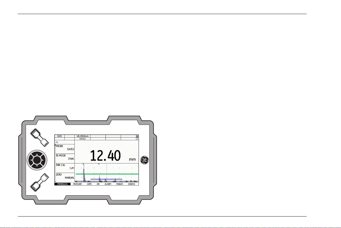
Normal display mode reading and A-scan
For toggling between the different display
modes and operating modes,
Operating modes and views, page 5-17.
Display mode reading and B-scan
see Section
DMS Go+ Edition 4 (05/2014) 4-3
Page 70

4 Principles of operation Display screen
Display mode Data Recorder
If a data recorder file is loaded, you will see the name
and the structure of the data recorder file above the cur
rent reading.
The functions to the left on the display screen are used
for navigating within the data recorder file.
Landscape and Portrait mode
You can change the screen display of DMS Go+ from
landscape to portrait mode.
4-4 Edition 4 (05/2014) DMS Go+
Page 71

Display screen 4 Principles of operation
Functions on the display screen
Function groups
The names of the seven function groups are shown at
the bottom of the display screen. The currently selected
function group is highlighted.
Functions
The functions of the currently selected function group
are shown on the left side of the display screen.
Icons and information
Keypad functions
You can see the current functions of the four function
keys in the top left corner of the display screen. The
functions are context-dependent and change during the
operation.
Data boxes
The current sound velocity of the material and the name
of the selected probe are displayed at the top center.
Six other data boxes are user-assignable for different
data and information.
DMS Go+ Edition 4 (05/2014) 4-5
Page 72

4 Principles of operation Display screen
Status display icons
The status displays in the top left corner of the display
screen, above the functions, inform about certain active
functions, operating modes, or operating status (
see
Section Status display icons, page 0-5).
Display of reading
The current reading is always displayed in enlarged
mode above the A-scan or B-scan.
If an alarm threshold is exceeded, the displayed reading
is red.
4-6 Edition 4 (05/2014) DMS Go+
Page 73

Navigation and function keys 4 Principles of operation
Note
4.3 Navigation and function keys
Keypad
The five keys of the keypad next to the display screen
are used
● for navigation between and within the function
groups,
● for changing settings, and
● for selecting adjustment values.
If a key is pressed for a longer time, the adjustment values change in larger increments.
The center key of the keypad is normally used for toggling between the display modes Landscape and Portrait.
In special contexts, the keys have further functions
which are described together with the corresponding ac
tion in this manual.
Function keys
Apart from the keypad, two groups of keys, including
two function keys each, are arranged next to the display
screen (
page 4-2).
The functions of three function keys are context-dependent and change automatically during the operation.
The current functions are displayed in the top left corner
of the display screen (
page 4-5).
The function of the function key number 4 is user-assignable (see Section Assignment of function key 4,
page 5-7).
see Section Overview of operator's controls,
see Section Keypad functions,
Power key
The key for powering the instrument on and off is located on the instrument side, next to the probe connectors.
-
DMS Go+ Edition 4 (05/2014) 4-7
Page 74

4 Principles of operation Navigation and function keys
Key combinations
You can carry out some functions by means of key combinations. To achieve this, you have to press several
function keys at the same time (
of operator's controls, page 4-2).
Function Keys
Screen shot Function key 1 + function key 2
Update Function key 2 + function key 4 + Power key
Reset Function key 1 + function key 4 + Power key
see Section Overview
4-8 Edition 4 (05/2014) DMS Go+
Page 75

Operational concept 4 Principles of operation
4.4 Operational concept
Changing the display views
The display view changes automatically after selecting
the corresponding instrument function or the operating
mode (function MODE).
Normal view reading and A-scan
Every time the DMS Go+ is powered on, the normal
view with the large display of reading and the functions
groups and functions can be seen.
View Data Recorder
If a data recorder file has been loaded, additional information about the file is automatically displayed above
the reading together with the file structure including the
saved readings.
A description of how to handle data recorder files is given in Chapter 6 Data Recorder.
DMS Go+ Edition 4 (05/2014) 4-9
Page 76

4 Principles of operation Operational concept
Selecting and setting functions
Shown below the A-scan are the seven function groups
which you can directly select using the keys of the key
pad. The name of the currently selected function group
is highlighted and the corresponding functions are dis
played in a list at the left screen edge.
A vertical scroll bar at the utmost screen edge shows the
current position in the list for function groups containing
more than four functions.
-
–Press the left or right arrow keys in order to choose
a function group.
– Press the down arrow key in order to select the first
function of the function group chosen previously.
– Press the left or right arrow keys in order to change
the setting.
– Press the function key 1 (function HOME) in order to
exit the function.
Coarse and fine adjustment of functions
You can choose between coarse and fine adjustment
for some functions.
Use the lower function keys to make the coarse adjustment. The value will then change either in large increments (e.g. for the function DISPLAY RANGE) or you
can choose from a series of factory-saved values (e.g.
for the function VELOCITY)
The fine adjustment is made by means of the left and
right arrow keys of the keypad. The fastness of change
is influenced by the duration of the key depression
during this (e.g. for the function VELOCITY).
4-10 Edition 4 (05/2014) DMS Go+
Page 77

Operational concept 4 Principles of operation
During the coarse adjustment, the name of the function is
displayed in capital letters (DISPLAY RANGE), whereas
it is displayed in lower-case letters during the fine adjust
ment (display range).
As long as a function is selected, you cannot toggle between the function groups. To toggle between the function groups, you have to press the function key 1 (function HOME) first in order to exit the function.
Key lock
If no function is selected, you can activate the key lock.
If the key lock is active, all keys except for the function
key 1 are locked and the instrument no longer reacts if
a key is pressed.
– Press the function key 1 (function LOCK) in order to
activate the key lock. The key function LOCK is then
displayed in the top left corner of the display screen.
– Press the function key 1 (function LOCK) once more
in order to deactivate the key lock. The instrument re
acts again when a key is pressed.
Disabled functions
If the option INSPECTOR is chosen in the function
MENU MODE, the functions are suppressed and cannot
be set.
Depending on other settings, individual functions can be
visible (
see Section Function lockout, page 5-8)
-
DMS Go+ Edition 4 (05/2014) 4-11
Page 78

4-12 Edition 4 (05/2014) DMS Go+
Page 79

Operation 5
DMS Go+ Edition 4 (05/2014) 5-1
Page 80

5 Operation Default settings
5.1 Default settings
Language setting
Use the function LANGUAGE (function group CONFIG)
to choose the language for the displayed texts.
The following languages are available:
● Bulgarian ● Chinese ● German
● English ● Finnish ● French
● Italian ● Japanese ● Dutch
● Norwegian ● Polish ● Portuguese
● Romanian ● Russian ● Swedish
● Spanish ● Czech ● Hungarian
– In the function group CONFIG, select the function
LANGUAGE.
– Choose the required language. The language chang-
es immediately.
5-2 Edition 4 (05/2014) DMS Go+
Page 81

Default settings 5 Operation
Units setting
You can use the function UNIT (function group CONFIG) to select the required units (mm or in). You can
change the units any time. All values are adjusted ac
cordingly.
– In the function group CONFIG, select the function
UNIT.
– Choose the required unit. The unit changes immedi-
ately.
-
Resolution setting
You can use the function RESOLUTION (function group
CONFIG) to select the resolution for the display of read
ings. If the setting AUTO is selected, the readings up to
100
mm are displayed with two decimal places (up to
10
in with three decimal places).
– In the function group CONFIG, select the function
RESOLUTION.
– Choose the required resolution. The display of read-
ings changes immediately.
-
DMS Go+ Edition 4 (05/2014) 5-3
Page 82

5 Operation Default settings
Radix
You can choose the radix symbol. All data are displayed
and saved using the selected radix.
– In the function group CONFIG, select the function
RADIX.
– Choose the required radix. The display of readings
changes immediately.
Last reading
You can choose the display mode for the thickness value measured last – after uncoupling and before coupling the next time.
– In the function group CONFIG, select the function
LAST READING.
– Choose the required display mode. The display of
readings changes immediately.
5-4 Edition 4 (05/2014) DMS Go+
Page 83

Default settings 5 Operation
ATTENTION
Date format, Date, and Time
You can set the date format, the date, and the time using the corresponding functions of the function group
CONFIG on the second operating level.
In view of a correct documentation, always
make sure that you are using the correct date
and the correct time. Remember to turn the
clock during the change from winter time to
summer time.
– In the function group CONFIG, select the function DT
FMT.
– Choose the required date format. The time format is
changed together with the date format.
– Select the function DATE TIME.
– Press the left or right arrow keys.
– Use the navigation to change the highlighted value
and switch over to the next value.
– Change the other values in the same way.
– Finally, press the function key 1 to exit the function.
The new values apply immediately.
DMS Go+ Edition 4 (05/2014) 5-5
Page 84

5 Operation Default settings
Selecting the instrument orientation
You can configure the instrument for right-handed or
left-handed operation (referred to the probe). The
screen display is then rotated through 180°, the func
tions of navigation and function keys are adjusted accordingly.
– In the function group CONFIG, select the function
ORIENTATION.
– Choose the required orientation. The screen display
is immediately switched over.
-
Display orientation
You can change the screen display of DMS Go+ from
landscape to portrait mode.
It is not possible to access the settings and parameters
in the portrait mode.
– Briefly press the center key of the keypad in order to
rotate the screen display by 90 degrees.
– Press the center key one more time in order to see
the original display mode again.
5-6 Edition 4 (05/2014) DMS Go+
Page 85

Default settings 5 Operation
Assignment of function key 4
You can assign a function to the function key 4 (see
Section Overview of operator's controls, page 4-2) to
be able to trigger this function any time. In this way, you
can switch for example from right-handed operation
over to left-handed operation by pressing the function
key
4 (option LH/RH).
The following settings are possible:
● NOT DEFINED (no function assigned)
● NOTE (choosing a comment, see page 6-20)
● µGRID (adding a MicroGrid, see page 6-29)
● LH/RH (instrument orientation, see page 5-6)
● OBSTR/CLEAR (no measurement possible or delete
reading,
see page 6-15 f.)
● FREEZE (display freeze, see page 5-52)
● CAL (calibration start, see page 5-25)
● ZOOM (gate magnifier, see page 5-53)
– In the function group CONFIG, select the function
FUNC KEY.
– Choose the required function.
– Press the function key 4 to test the function.
DMS Go+ Edition 4 (05/2014) 5-7
Page 86

5 Operation Default settings
Function lockout
You can disable the access to the setup functions of the
instrument in order to prevent, for example, any acci
dental changes to settings. The functions are then no
longer displayed on the screen.
When the access to the functions is disabled, you can
exclude individual functions from the lockout and make
them visible. These functions are then selectable and
can be changed or set in spite of the general lockout.
-
Disabling all setup functions
– In the function group CONFIG, select the function
MENU
MODE.
– Choose the option INSPECTOR in order to disable
the access to all setup functions.
– Choose the option EXPERT in order to enable the ac-
cess to all setup functions.
– Check whether the functions are visible or not ac-
cording to the selected setting.
5-8 Edition 4 (05/2014) DMS Go+
Page 87

Default settings 5 Operation
Enabling individual setup functions
– In the function group CONFIG, select the function
LOCKOUT.
– Press the left or right arrow keys. A selection menu
is displayed.
– Press one of the left or right arrow keys in order to
select the function group.
– Press one of the up or down arrow keys in order to
select the function.
– Press the center key of the keypad in order to exclude
the selected function from the general lockout. The
function is marked with a cross.
– Select other exceptions in the same way.
– Finally, press the function key 2 (function CONFIRM)
in order to exit the selection menu and to save the se
lection.
– Check whether the marked functions are visible in the
corresponding function groups and can be changed
or set.
-
DMS Go+ Edition 4 (05/2014) 5-9
Page 88

5 Operation Default settings
ATTENTION
Password protection
You can protect the access to the setup functions with a
password. This makes the access to the disabled func
tions only possible after entering a password (see Section Function lockout, page 5-8).
To activate the password protection, you have to set a
password. After saving the password, it is only possible
to switch to the EXPERT mode after entering the pass
word.
Saving a new password
After saving the password, it is only possible
to have full access to the instrument func
tions after entering the password. If the password is lost, you have to reset the instrument
(
see Section Factory default setting (Re-
set), page 3-12).
-
You can save a password only if there is no password
protection yet or if the EXPERT mode is active (
Section Function lockout, page 5-8).
-
– In the function group CONFIG, select the function
PASSWORD.
– Press one of the left or right arrow keys.
– Press the arrow keys to mark the first character for
the password.
– Press the center key of the keypad to select the
marked character.
– Choose other characters in the same way.
– Press the function key 2 (function BKSP) in order to
delete the last character.
– Press the function key 4 (function NEXT) and set the
password again to check it.
– Press the function key 4 (function NEXT). The pass-
word is saved and immediately valid.
see
5-10 Edition 4 (05/2014) DMS Go+
Page 89

Default settings 5 Operation
Changing a password
You can change the password at any time. To do this,
you must first enter the current password.
– In the function group CONFIG, select the function
PASSWORD.
– Press one of the left or right arrow keys.
– Press the arrow keys to mark the first character for
the current password.
– Press the center key of the keypad to select the
marked character.
– Choose other characters in the same way.
– Press the function key 4 (function NEXT).
– Set the new password (see Section Saving a new
password, page 5-10).
Deactivating password protection
To deactivate the password protection, proceed in the
same way as for changing the password. Instead of a
new password, however, you don't choose any charac
ters.
– In the function group CONFIG, select the function
PASSWORD.
– Press one of the left or right arrow keys.
– Press the arrow keys to mark the first character for
the current password.
– Press the center key of the keypad to select the
marked character.
– Choose other characters in the same way.
– Press the function key 4 (function NEXT). However,
do not choose any characters at this point.
– Press the function key 4 (function NEXT) and, to
check, the function key
4 one more time (function
NEXT). The password protection is deactivated.
-
DMS Go+ Edition 4 (05/2014) 5-11
Page 90

5 Operation Default settings
Power saving mode
To save power during longer stops or breaks, you can
activate the automatic power down function of the in
strument after a preset time. The instrument is powered
down if no operation takes place during this time. After
that, you have to power the instrument on again using
the Power key.
If you choose the option MANUAL, the instrument is not
powered down automatically.
-
You have a choice between the following automatic
power down times:
● 1 min
● 2 min
● 3 min
● 4 min
● 5 min
● 10 min
● 15 min
● 30 min
– In the function group CONFIG, select the function
POWER DOWN.
– Choose the required power down time or the option
MANUAL.
5-12 Edition 4 (05/2014) DMS Go+
Page 91

Default settings 5 Operation
Configuring data boxes
You can use the function RESULTS to choose the data
to be displayed in the six data boxes at the top of the
screen display (
page 4-5).
see Section Icons and information,
You have a choice between the following data:
● OFF (no display)
● P-DLY (probe delay)
● LOC (measuring location)
● M-GAIN (maximum gain setting)
● TEMP (material temperature setting)
● GAIN (current gain)
● T-THK (temperature-compensated wall thickness)
● THK (measured wall thickness)
● C-THK (coating thickness in the operating mode
TopCOAT)
DMS Go+ Edition 4 (05/2014) 5-13
Page 92

5 Operation Default settings
– In the function group MEASURE, select the function
RESULTS.
– Press one of the left or right arrow keys. A selection
menu is displayed.
– Press one of the up or down arrow keys in order to
mark the required data box.
– Press one of the left or right arrow keys in order to
select the content for the marked data box.
– Configure the other data boxes in the same way.
– Finally, press the function key 1 (function EXIT) in or-
der to exit the selection menu and to save the selection. The selected data are then displayed in the data
boxes.
5-14 Edition 4 (05/2014) DMS Go+
Page 93

Default settings of the display 5 Operation
Note
Note
5.2 Default settings of the display
The DMS Go+ is equipped with a high-resolution color
display. You can optimize the display according to your
own viewing habits and to the operating environment.
Setting the brightness
You can set the brightness of the display and select a
value from 1 to 10 for this purpose.
A high brightness value increases the power
consumption, due to which the operating
time is reduced in battery operation.
– In the function group CONFIG, select the function
BRIGHTNESS.
– Choose the required value. The display brightness
changes immediately.
You can extend the operating time by means
of the power saver function (
Power saving mode, page 5-12).
see Section
DMS Go+ Edition 4 (05/2014) 5-15
Page 94

5 Operation Default settings of the display
Note
Selecting the color scheme
All color schemes are suitable for indoor use.
You can choose one of four color schemes. The color
scheme determines the color of all displays and of the
background.
For outdoor use, we recommend SCHEME
and SCHEME
4.
– In the function group CONFIG, select the function
COLOR.
– Select the required color scheme. The screen display
changes immediately.
3
5-16 Edition 4 (05/2014) DMS Go+
Page 95

Operating modes and views 5 Operation
5.3 Operating modes and views
You can choose from different operating modes and display views for different tasks.
● THICKNESS Default setting for general thickness
measurements,
● A-SCAN A-scan view, see page 5-47
● B-SCAN B-scan profile, see page 5-42
● MIN/MAX MIN/MAX mode, see page 5-40
● DIFF Differential value display,
see page 5-46
see page 5-32
Changing the operating mode or view
– In the function group MEASURE, select the function
MODE.
– Select the required operating mode or view. The dis-
play view changes immediately.
DMS Go+ Edition 4 (05/2014) 5-17
Page 96

5 Operation Saving the settings
Note
5.4 Saving the settings
The file name can consist of a maximum of
20
characters.
– In the function group PARAM, select the function
SAVE P-SET.
– Press one of the left or right arrow keys.
– Press the arrow keys to mark the first character for
the file name.
– Press the center key of the keypad to select the
marked character.
– Choose other characters in the same way.
You can save the current instrument settings to a file on
the SD memory card. The files for the DMS
the file extension DGO and are saved to the directory
DMSGO\DATASETS on the memory card.
Go+ have
– Press the function key 2 (function BKSP) in order to
delete the last character.
– Finally, press the function key 4 (function CONFIRM)
in order to save the file with the parameter data set
under the specified name.
5-18 Edition 4 (05/2014) DMS Go+
Page 97

Saving the settings 5 Operation
Note
Note
Loading settings
You can load and use instrument settings saved to the
SD memory card.
You can only load files with the file extension
DGO in the directory DMSGO\DATASETS.
Other files are not displayed for selection.
– In the function group PARAM, select the function
LOAD P-SET.
– Press one of the left or right arrow keys.
– Press the arrow keys to select the required file.
– Press the function key 2 (function ENTER) to load the
selected file.
The instrument settings of the selected dataset are
loaded, and they are immediately active after closing
the loading process.
Deleting settings
You can delete instrument settings saved to the SD
memory card.
You can only delete files with the file extension DGO in the directory DMSGO\DATASETS. Other files are not displayed for
selection.
– In the function group PARAM, select the function
LOAD P-SET.
– Press one of the left or right arrow keys.
– Press the arrow keys to select the required file.
– Press the function key 3 (function DELETE) to delete
the selected file.
– Confirm the safety prompt. The dataset file is deleted.
DMS Go+ Edition 4 (05/2014) 5-19
Page 98

5 Operation Preparing for measurements
Note
5.5 Preparing for measurements
You can use the DMS Go+ to measure wall thicknesses
or distances and to assess residual wall thicknesses in
a simple way. The measured value is displayed directly.
Depending on the task definition, you can apply one of
the following measuring methods:
● Measurement of residual wall thickness up to the first
echo with dual-element probes, for example in the
event of corrosion.
● Measurement of a multi-echo sequence with good
surfaces on both sides of the test object.
● Wall thickness measurement through coating by
evaluating the multi-echo sequence (DUAL-MULTI).
● Simultaneous measurement of wall thickness and
coating thickness with single echo (TopCOAT, only
with DMS Go+ TC).
● Wall thickness and residual wall thickness measure-
ment with a simultaneous determination of the current sound velocity (Auto-V, only with DMS Go+ TC).
To prepare for measurements, you have to:
● Select a suitable probe.
● Select the suitable measurement mode.
● Calibrate the A-scan display.
● Calibrate the instrument for the selected probe and
measurement mode.
– Connect a suitable probe (see Section Connecting a
probe, page 3-9).
– Power the instrument on (see Section Starting the
DMS Go+, page 3-11).
The further steps are described in detail in the following.
The functions TopCOAT and Auto-V are described in chapter 7 of this manual.
5-20 Edition 4 (05/2014) DMS Go+
Page 99

Preparing for measurements 5 Operation
Note
Choosing the probe type
After connecting a suitable probe for the task, you have
to choose the probe type to adjust the DMS
Go+ to the
probe.
The choice of measurement modes as well as individual
functions and parameters available likewise depends on
the selected probe type. The composition of the individ
ual function groups varies accordingly.
You have a choice between the following probes:
● A2 DFR ● CA211A ● OSS10
● D790 ● DA301 ● DA303
● DA312 ● DA312B16 ● DA501
● DA503 ● DA507 ● DA512
● DA590 ● DIALOG ● DP104
● FH2E ● HT400A ● KBA525
● KBA560 ● TC560
When a dialog probe (probe designation
DA4... or ...-D) is connected, the DMS
receives the necessary data from the probe
automatically. In that case, you don't have to
choose the probe type any more. It is auto
-
matically entered after connecting the probe.
– In the function group PROBE&CAL, select the func-
tion PROBE.
– Choose the connected probe. The instrument is im-
mediately adjusted.
Go+
-
DMS Go+ Edition 4 (05/2014) 5-21
Page 100

5 Operation Preparing for measurements
Choosing the measurement mode
You have to choose the suitable measurement mode for
the task. By doing so, you define the method for operat
ing the instrument or the data used for determining the
measurement result.
You have a choice between the following measurement
modes:
S-IP
The measurement mode S-IP is available for single-element probes.
The wall thickness is determined on the basis of the ultrasonic time of flight from zero up to the last zero crossing before the first flank crossing detected in gate A. The
ultrasonic time of flight is corrected by the probe delay
line which is calculated during the probe zero offset (
Section Probe zero offset, page 5-25).
This measurement mode is suitable for non-coated materials with smooth, parallel surfaces.
see
S-PEAK
The measurement mode S-PEAK is available for single-
element probes.
The wall thickness is determined on the basis of the ul-
trasonic time of flight from the last zero crossing before
the amplitude peak in gate
before the peak echo in gate
A up to the last zero crossing
B.
This measurement mode is suitable for non-coated materials with smooth, parallel surfaces.
S-FLANK
The measurement mode S-FLANK is available for single-element probes.
The wall thickness is determined on the basis of the ultrasonic time of flight from the last zero crossing before
the first flank detected in gate
A up to the last zero
crossing before the first flank crossing detected in
gate
B.
This measurement mode is suitable for coated materials
with smooth, parallel surfaces.
5-22 Edition 4 (05/2014) DMS Go+
 Loading...