

Page 1

CL 5
Operating Manual
Ident-Nr. 021-002-296
Issue 01
Page 2

Issue 01, 04/2005 applies to software version XX.04.XX
Page 3

CL 5 Issue 01, 04/05 0-1
Contents
1 General Information........................... 1-1
1.1 Supplying Power to the CL 5................. 1-2
1.2 Powering On and Off the Instrument .... 1-4
1.3 Key Features of the CL 5........................ 1-4
CL 5 Precision Thickness
Measurement Base Instrument .............. 1-5
Instrument Options .................................. 1-6
1.4 Whats in this Manual ............................ 1-6
2 Understanding the Keypad,
Menu System, and Displays ............. 2-1
2.1 Keypad Features .................................... 2-2
2.2 Interpreting Display Screens ................. 2-2
2.3 Working with the Configuration
Display .................................................2-10
3 Setting Up the CL 5 ........................... 3-1
3.1 Connecting a Probe and Loading a
Setup File ............................................. 3-3
3.2 Configuring the Instrument ................... 3-6
3.2.1 Setting Instrument Gain ................ 3-8
3.2.2 Setting Update Rate ..................... 3-8
3.2.3 Setting Nominal Thickness ........... 3-8
3.3 Instrument Calibration........................... 3-9
3.4 Setting the Maximum and Minimum
Alarms .................................................. 3-9
3.5 Creating and Erasing Custom Setup
Files .....................................................3-11
3.6 Locking and Unlocking Instrument
Settings ...............................................3-14
4 Measuring Thickness ........................ 4-1
4.1 Selecting the Displayed View ................ 4-2
4.2 Normal Measurement Mode
(No A-Scan) .......................................... 4-3
4.3 Min Scan and Max Scan Measurement
Mode..................................................... 4-6
Page 4

0-2 Issue 01, 04/05 CL 5
Contents
4.4 Differential/Rate-of-Reduction
Measurement Mode ............................. 4-8
4.5 Thickness + A-Scan Measurement
Mode (Optional) ..................................4-10
4.6 Velocity Measurement Mode
(Optional) ............................................. 4-8
5 Using the Optional Data Recorder ... 5-1
5.1 Creating a New Data Recorder File ....... 5-2
5.2 Recalling and Erasing Stored Data
Recorder Files ...................................... 5-4
5.3 Recording Thickness and Velocity
Measurements in Data Recorder
Files ...................................................... 5-5
5.3.1 Recording A-Scans in Data
Recorder Files .............................. 5-6
5.3.2 Navigating Through Data
Recorder Files .............................. 5-6
5.4 Printing a Report.................................... 5-6
6 I/O Features........................................ 6-1
6.1 Transmitting Data to an External
Device ..................................................... 6-2
6.2 Setting Communication Speed
(Baud Rate) and Connecting to a PC... 6-4
6.3 Remote Commands ............................... 6-4
7 Specifications
7.1 Instrument Specifications ..................... 7-2
7.2 A-Scan Option Features ......................... 7-5
7.3 Velocity Measurement Option
Features................................................ 7-5
7.4 Data Recorder Option Features ............. 7-6
7.5 CL 5 Probe/Transducer
Specifications....................................... 7-6
Page 5

CL 5 Issue 01, 04/05 0-3
Contents
8 Maintenance
Care of the Instrument .................................... 8-2
9 Appendix............................................ 9-1
9.1 Resetting the Operating Software ......... 9-2
9.2 Upgrading the Operating Software ....... 9-2
9.3 EMC Documentation .............................. 9-3
9.4 Manufacturer/Service Addresses .......... 9-5
10 Index ................................................. 10-1
Page 6

0-4 Issue 01, 04/05 CL 5
Important Notice
Important Notice
The following information must be read and understood
by any user of a GE Inspection Technologies ultrasonic
thickness gauge. Failure to follow these instructions
can lead to errors in thickness measurements or other
test results. Decisions based on erroneous results can,
in turn, lead to property damage, personal injury or
death.
General Warnings
Proper use of ultrasonic test equipment requires three
essential elements:
Selection of the correct test equipment.
Knowledge of the specific test application
requirements.
Training on the part of the instrument operator.
This operating manual provides instruction in the basic
set up and operation of the thickness gauge. There are,
however, additional factors which affect the use of
ultrasonic test equipment. Specific information
regarding these additional factors is beyond the scope
of this manual. The operator should refer to textbooks
on the subject of ultrasonic testing for more detailed
information.
Operator Training
Operators must receive adequate training before using
ultrasonic test equipment. Operators must be trained in
general ultrasonic testing procedures and in the set up
and performance required by a particular test.
Operators must understand:
Soundwave propagation theory.
Effects of the velocity of sound of the test material.
Behavior of the sound wave where two different
materials are in contact.
Areas covered by the sound beam.
More specific information about operator training, qualification, certification, and test specifications is available from various technical societies, industry groups,
and government agencies.
Page 7

CL 5 Issue 01, 04/05 0-5
Important Notice
Testing Limitations
In ultrasonic testing, information is obtained only from
within the limits of the sound beam. Operators must
exercise great caution in making inferences about the
test material outside the limits of the sound beam. For
example, when testing large materials it may be
impossible or impractical to inspect the entire test
piece.
When a less-than-complete inspection is to be
performed, the operator must be shown the specific
areas to inspect. Inferences about the condition of
areas not inspected, based on data from the evaluated
areas, should only be attempted by personnel fully
trained in applicable statistical and probability
techniques. In particular, materials subject to erosion
or corrosion, in which conditions can vary significantly
in any given area, should only be evaluated by fully
trained and experienced operators.
Sound beams reflect from the first interior surface
encountered. Because of part geometry and overlapped flaws or overlapped surfaces, thickness gauges
may measure the distance to an internal flaw rather
than to the back wall of the material. Operators must
take steps to ensure that the entire thickness of the
test material is being examined.
Ultrasonic Thickness Measurement Critical
Operating Procedures
The following operating procedures must be observed
by all users of ultrasonic thickness gauges in order to
minimize errors in test results.
1. Calibration of Sound Velocity
The principle of operation of an ultrasonic thickness
gauge is that the instrument measures the time of flight
of an ultrasonic pulse through the test piece and
multiplies this time by the velocity of sound in the
material. Thickness measuring error is minimized by
ensuring that the sound velocity to which the instrument is calibrated is the sound velocity of the material
being tested. Actual sound velocities in materials often
vary significantly from the values found in published
tables. In all cases, best results are obtained if the
instrument is calibrated on a velocity reference block
made from the same material as the test piece; this
block should be flat and smooth and as thick as the
maximum thickness of the test piece.
Page 8

0-6 Issue 01, 04/05 CL 5
Important Notice
Operators should also be aware that the sound velocity
may not be constant in the material being tested; heat
treating, for example, can cause significant changes in
sound velocity. This must be considered when evaluating the accuracy of the thickness provided by this
instrument. Instruments should always be calibrated
before testing, and the calibration should be checked
after testing, to minimize testing errors.
2. Probe Zero Procedure
When performing a one-point calibration with a contact
probe, the probe zero procedure must be performed as
described in this manual. The probe zero block should
be clean, in good condition, and without noticeable
wear. Failure to properly perform the probe zero
procedure will cause inaccurate thickness readings.
3. Effects of Temperature on Calibration
Temperature variations change the sound velocity of
materials and transducer delay lines and, therefore,
calibrations. All calibrations should be performed onsite, and with test blocks at the same temperature as
the test piece, to minimize errors due to temperature
variations.
4. Transducer Selection
The transducer used in testing must be in good
condition without noticeable wear of the front surface.
Badly worn transducers will have a reduced effective
measuring range. The specified range of the transducer
must include the complete range of thicknesses to be
tested. The temperature of the material to be tested
must be within the transducers temperature range.
5. Use of Couplants
Operators must be familiar with the use of ultrasonic
couplants. Testing skills must be developed so that
couplant is used and applied in a consistent manner to
minimize variations in couplant layer thickness and
errors in test results. Calibration and actual testing
should be performed under similar coupling conditions,
using a minimum amount of couplant and applying
consistent pressure on the transducer.
6. Doubling
Ultrasonic thickness gauges will, under certain
conditions, display readings which are twice (or, in
some cases, three times) the actual material thickness
Page 9

CL 5 Issue 01, 04/05 0-7
Important Notice
being measured. This effect, commonly known as
doubling, can occur below the minimum specified
range of the transducer. If the transducer being used is
worn, doubling is possible at a thickness greater than
the minimum of the specified range.
When using a new transducer, any reading which is
less than twice the minimum specified range of the
transducer may be a doubled reading, and the
thickness of the material being tested should be
verified by the use of other methods. If the transducer
shows any sign of wear, doubling may occur at a
second echo or other echo signal combinations may
produce a readable signal. The instrument reading and
apparent thickness are up to about twice the actual
value, resulting in a thickness greater than twice the
minimum of the specified range. This thickness should
be determined by calibrating the instrument/transducer
combination on reference blocks that represent the
complete range of possible thicknesses that may be
encountered in testing. This is particularly important
when the test piece is being ultrasonically measured for
the first time or in any case where the history of thickness of the test specimen is unknown.
Safety Information
Attention:
The CL 5 is an instrument for materials testing. Any
use for medical applications or other purposes is not
allowed.
The CL 5 may only be used in industrial environments.
The CL 5 can be operated with batteries or while
plugged into an electrical outlet using the AC charger.
The power supply unit has the electrical safety class II.
Batteries:
For the battery operation of the CL 5, we recommend
the use of a lithium-polt battery pack provided.
Operation using alkaline batteries, NiMH or NiCAD
cells is possible. You should only use the products
recommended by us for the battery operation. Do not
attempt to use any lithium batteries that are not
provided with the instrument. Do not attempt to charge
the provided batteries on an outside charger.
Page 10

0-8 Issue 01, 04/05 CL 5
Important Notice
Software:
According to the current state of the art, software is
never completely free from errors. Before using any
software-controlled test equipment, please make sure
that the required functions operate perfectly in the
intended combination.
Defects/errors and exceptional stresses
If you have reason to believe that a safe operation of
your CL 5 is no longer possible, you have to disconnect
the instrument and secure it against unintentional
reconnection. Remove the batteries if necessary.
A safe operation is no longer possible e.g.:
The instrument shows visible damages
The instrument no longer operates perfectly
After prolonged storage under adverse conditions like
exceptional temperatures and/or especially high air
humidity, or corrosive environmental conditions.
Being subjected to heavy stresses during
transportation
Service
Every effort has been made to provide you with a
reliable product. However, should service become
necessary, GE Inspection Technologies, has established a number of Factory Trained Service Centers.
For the location of the nearest facility refer to section
9.4 of this manual.
Page 11

CL 5 Issue 01, 04/05 1-1
General Information 1
Page 12

1-2 Issue 01, 04/05 CL 5
General Information Supplying Power to the CL 5
The CL 5 is an ultrasonic precision thickness
measurement device. Its available with optional live
A-Scan display, acoustic velocity measurement
capability, and a data recorder in which as many
10,000 thickness measurements per file can be stored.
This chapter of your manual introduces the key
features of the CL 5 and the contents of this operating
manual. The next chapter explains the keypad
functions and display-menu contents. Closely
reviewing the material in these two chapters will help
you make better use of the more detailed information
found throughout the rest of this manual.
In this chapter, youll learn
How to install batteries or connect the AC power
adapter to the instrument (Section 1.1)
How to Power on and off the instrument
(Section 1.2)
The features of the instrument and base instrument
package contents (Section 1.3)
The general content of each chapter in this manual
(Section 1.4)
1.1 Supplying Power to the
CL 5
The instrument is powered by a Lithium (Li) battery
pack.
It will also accept three AA size Alkaline, NiCAD,
or NiMH (nickel metal hydride) battery types.
The Lithium battery, which is recommended, will
provide up to approximately 25 hours of service life.
This pack (and only this pack) may be recharged in
the instrument using the charger provided with your
instrument.
When other types of rechargeable batteries are
used, they must be removed from the instrument for
charging.
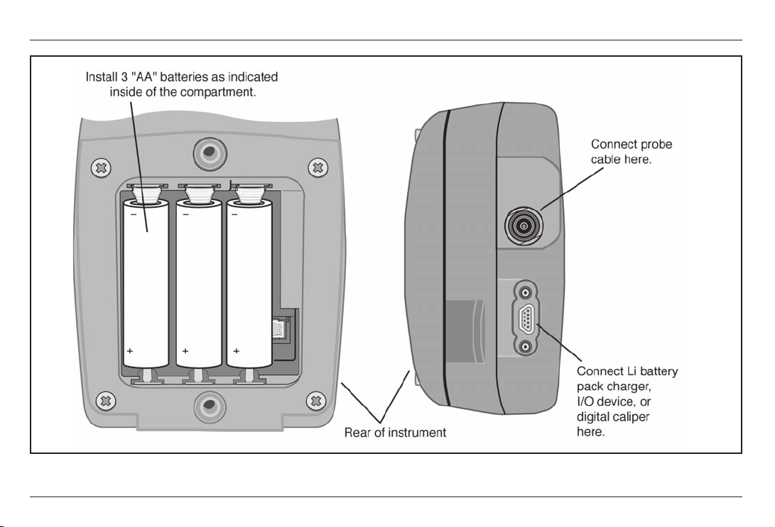
To install batteries, remove the battery-compartment
cover as shown in Figure 1-1. After inserting the Li
pack or three AA batteries according to the polarity
indicated in the battery compartment, replace the
compartment cover. Instructions on specifying battery
type are found in Section 3.2.
Page 13
CL 5 Issue 01, 04/05 1-3
Supplying Power to the CL 5
General Information
FIGURE 1-1Insert batteries as shown here. Notice the location of the External Power Connector to which the
instruments Li battery packs charger be connected.
Page 14
1-4 Issue 01, 04/05 CL 5
. Note:
When the battery indicator is in the last quarter as
indicated by the display-screen symbol
, replace
the batteries as soon as possible. The CL 5
automatically shuts off when batteries are too weak for
reliable operation. However, settings are saved and
restored when the instrument is turned on again. When
testing in remote locations, always carry spare
batteries.
. Note:
The instrument can be operated while the Li battery
packs charger is connected. This charger is connected
to the instrument though the connector shown in
Figure 1-1. When the charger is powering the
instrument,
appears on the display screen. The
charger may only be connected when the GE
Inspection Technologies Li battery pack is installed in
the instrument.
1.2 Powering On and Off the
Instrument
After a power source has been provided, power on the
instrument by pressing and holding
until the
instrument turns on. Press and hold when the
instrument is on to turn if off.
1.3 Key Features of the CL 5
Large Hollow/filled thickness digits
Alarm Bar Graph
Standard and Custom parameter setups
Supports delay and contact probes
Alphanumeric naming of data locations
Lockout feature with password access
Lightweight .75 lbs (.34 Kg)
Large LCD Display with Backlight and Adjustable
Contrast
General Information Powering On and Off the Instrument
Page 15

CL 5 Issue 01, 04/05 1-5
Approximately 25 hours life with the Li battery
pack or 3 AA alkaline batteries
Easy-to-use, single-level menu system
Multiple display-screen languages
User-selectable measurement resolution to 0.0001
inch (0.001 mm)
Normal (thickness), Min-Scan, Max-Scan, and
Differential/Rate of Reduction Measurement Modes
are Standard
Optional A-Scan provides A-Scan plus Thickness
Optional Data Recorder stores up to 10,000 thick-
ness measurements with A-Scan images attached
in as many as 120 data recorder files
Optional Velocity Measurement Mode includes an
electronically connected digital caliper for exact
measurement and automatic input of nominal
thickness
Field upgrades available via the GE Inspection
Technologies web site
Compatible with UltraMATE
©
and UltraMATE LITE
©
software programs
CL 5 Precision Thickness Measurement
Base Instrument
Contents of the CL 5 Base Instrument
CL 5 Instrument
Lithium Battery Pack
Lithium Battery Pack Recharger
Plastic Carrying Case
Wire Stand
Two-Point Check Block (uncertified)
Couplant Sample
Firmware Upgrade CD-ROM (requires Serial PC
cable)
Operating Manual
Operating Instruction Card
Certificate of Conformity
Key Features of the CL 5 General Information
Page 16

1-6 Issue 01, 04/05 CL 5
Instrument Options
A-Scan Upgrade Option
Data Recorder Upgrade Option
Velocity Measurement Option
1.4 Whats in this Manual
The CL 5 Operating Manual is divided into ten
chapters. All chapters except 4 and 5 apply to all
instruments. The last two sections of Chapter 4 apply
only to instruments equipped with the A-Scan or
Velocity measurement options. Chapter 5 applies only
to instruments equipped with the Data Recorder option.
Note that any CL 5 can be retrofitted to incorporate
these options. Following is a summary of Chapters 1
through 10:
Chapter 1General Introduction
Supplying Power to the instrument
Powering on and off the instrument
Overview of instrument features
Explanation of the operating manual contents
Chapter 2Understanding the Keypad, Menu
System, and Displays
Operations performed by each key
Navigating the display screens
Overview of menu functions
Explanation of display features (base model, data
recorder, and A-Scan equipped instruments)
Definition of icons
Chapter 3Setting Up the CL 5
Install a probe and configure the instrument by
loading a setup file
Set up the instrument display appearance (for base
model and A-Scan equipped instruments) and make
other configuration settings
General Information Whats in the Manual
Page 17

CL 5 Issue 01, 04/05 1-7
Whats in this Manual
General Information
Adjust the instrument gain setting
Specify the nominal material thickness
Calibrate and zero the instrument/probe combination
Set maximum and minimum alarm values
Create and erase custom setup files
Lock and unlock instrument controls
Chapter 4Measuring Thickness
Specify and use the Normal measurement mode (No
A-Scan)
Operate in Min-Scan and Max-Scan Measurement
mode
Operate in Differential/Rate of Reduction
measurement mode
Select and interpret the A-Scan plus Thickness
measurement mode (Optional)
Magnify the displayed A-Scan using the Zoom
control
Freeze the thickness reading and A-Scan
Connect the digital caliper and measure acoustic
velocity (Optional)
Chapter 5Using the Optional Data Recorder
Create, recall, and delete data recorder files
Store A-Scan and thickness readings in data
recorder files
Navigate data recorder file locations
Attach notes to the data recorder file
Print reports
Chapter 6I/O Technical Details
Configure the instrument to communicate with PCs
and printers
Thickness value format
Remote control codes
Page 18

1-8 Issue 01, 04/05 CL 5
Chapter 7Specifications
Chapter 8Maintenance
Chapter 9Appendix
Reset the operating software
Upgrade the operating software
EMC documentation
How to obtain service
Chapter 10Index
Whats in this Manual General Information
Page 19

CL 5 Issue 01, 04/05 2-1
Understanding the Keypad,
Menu System, and Displays
2
Page 20

2-2 Issue 01, 04/05 CL 5
Understanding the Keypad, Menu System, and Displays Keypad Features
The CL 5s display, keypad, and functional commands
are easy to interpret and use. In this chapter youll find
a brief explanation of all display and keypad features.
Youll also find references to manual sections where
more detailed information is available.
Note that the CL 5s display screen contents vary
depending on the optional features installed and the
operational settings selected. Display screens shown
in this chapter represent those found in all instrument
configurations including:
Base Model
A-Scan Option Installed
Data Recorder Option Installed
A-Scan and Data Recorder Options Installed
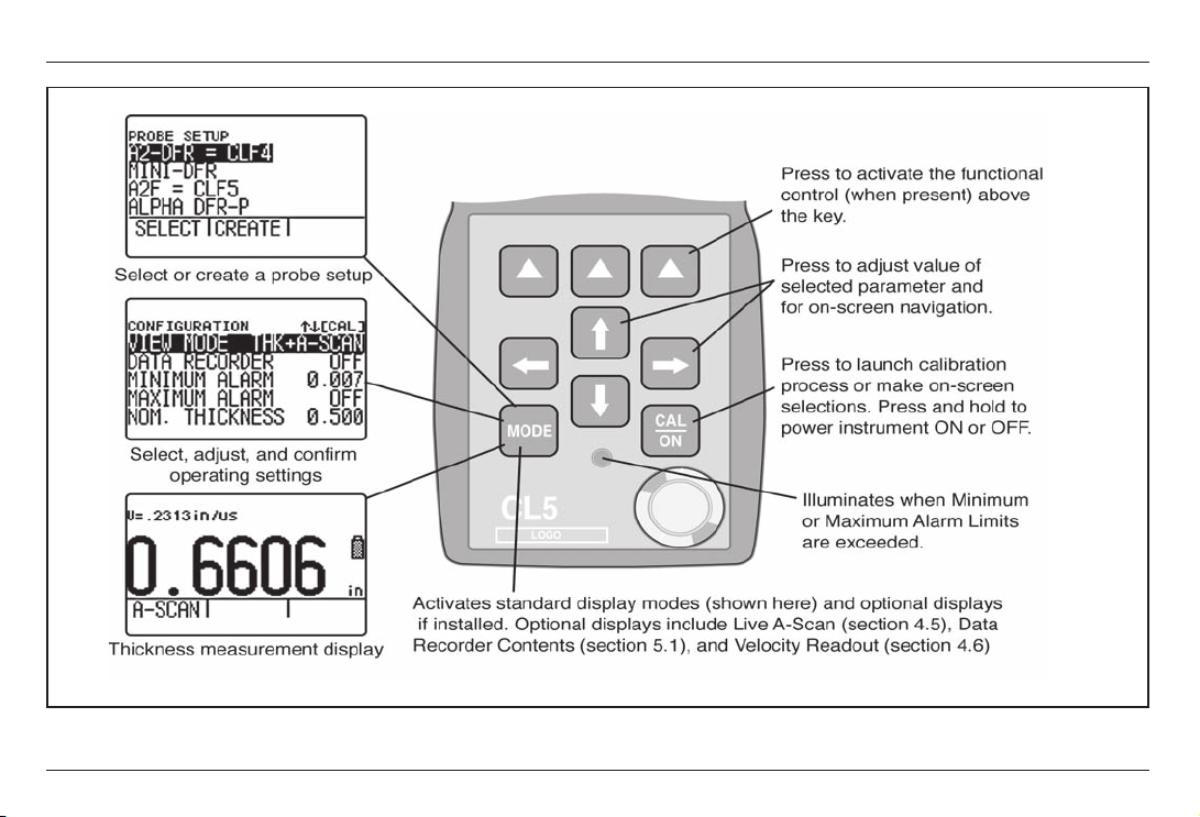
2.1 Keypad Features
The instruments keypad includes dedicated keys
(
and ), arrow keys ( , , , ), and three
virtual function keys ( ). Key functions are described
in Figure 2-1.
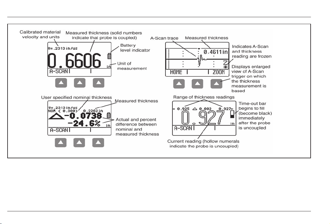
2.2 Interpreting Display Screens
This section of your manual describes the layout of the
CL 5s primary display modes including the:
Measurement Display Mode Indicates measured
thickness, contains status icons, displays data
recorder location and file name (when this option is
installed and activated), and the live A-Scan display
(when this option is installed and activated). Figure
2-2 shows four representative display screens.
Page 21
CL 5 Issue 01, 04/05 2-3
Interpreting Display Screens
Understanding the Keypad, Menu System, and Displays
FIGURE 2-1Key Functions
Page 22
2-4 Issue 01, 04/05 CL 5
Interpreting Display Screens
Understanding the Keypad, Menu System, and Displays
FIGURE 2-2MEASUREMENT DISPLAY MODE The displays appearance varies based on installed instrument
options as well as instrument display settings. NORMAL view mode is available in all instruments regardless of the
installed options. Additional measurement view modes are available when the A-Scan or Data Recorder options are
installed. Depending on the view selected, the display may contain the current thickness value, a live A-Scan,
minimum thickness value, maximum thickness value, and differential value in the unit of measurement or as a
percentage when compared to a nominal value.
Page 23

CL 5 Issue 01, 04/05 2-5
Understanding the Keypad, Menu System, and Displays Interpreting Display Screens
Probe Setup Display Mode Allows the user to
select a standard preloaded instrument setup (each
matched to a specific probe model) or a custom
user-defined setup. Custom Setups are created
using this display screen. They can be downloaded
to a PC using the UltraMATE© software package
and then downloaded into any CL 5 instrument. The
contents of a Custom Setup file vary depending on
the instruments configuration. See Section 3.5 for
information on custom setups. (Figure 2-3).
File Display Mode Allows the user to create and
store thickness readings in data recorder files. This
feature is only available when the data recorder
option is installed and activated. Accompanying
A-Scans can be stored with thickness readings by
holding
below the SEND Function for three
seconds. (Figure 2-4)
Configuration Display Mode Instrument controls
are accessed through this screen. The controls
listed on the configuration display screen vary
depending on the installed options. (Figure 2-5)
Page 24
2-6 Issue 01, 04/05 CL 5
Interpreting Display Screens
Understanding the Keypad, Menu System, and Displays
FIGURE 2-3PROBE SETUP DISPLAY MODE Allows selection of a preloaded or Custom Setup file, which
automatically recalls all parameter settings. Note that Custom Setups can be downloaded from an UltraMate©
equipped PC to any instrument, or created using this display (see Section 3.5 for information on Custom Setup files).
Page 25
CL 5 Issue 01, 04/05 2-7
Understanding the Keypad, Menu System, and Displays Interpreting Display Screens
FIGURE 2-4FILE DISPLAY MODE When installed and activated, the data recorder option allows users to create
data recorder files, store thickness readings (and accompanying A-Scans), and navigate through file contents as
shown here. See Chapter 5 to work with Data Recorder files.
Page 26
2-8 Issue 01, 04/05 CL 5
Interpreting Display Screens
Understanding the Keypad, Menu System, and Displays
FIGURE 2-5CONFIGURATION DISPLAY MODE The contents of the Configuration display depend on the
instruments installed-option configuration. All settings listed on the Configuration display are described in Section
2.3.
Page 27
CL 5 Issue 01, 04/05 2-9
2.3 Working with the
Configuration Display
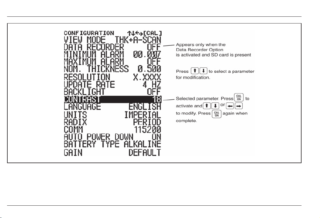
The Configuration display is accessed by pressing .
With this screen displayed, you can adjust most CL 5
controls.
VIEW MODE In base-model units this parameter
offers 4 settings. In A-Scan equipped instruments this
parameter allows the measurement and live A-Scan to
be displayed. See Section 4.1 to select the view to be
displayed.
DATA RECORDER When the optional data recorder
is installed, setting this parameter to ON activates the
file recording capability and the data recorder file
display.
MINIMUM ALARM Enables and sets the minimum
alarm value. (Section 3.4)
MAXIMUM ALARM Enables and sets the maximum
alarm value. (Section 3.4)
NOMINAL THICKNESS Set the nominal thickness
value that is then used to calculate and the differential
and rate of reduction measurement values when
selected by the VIEW MODE parameter.
(Section 3.2.3)
RESOLUTION Controls the format (number of
decimal places) of the thickness measurement
displayed, printed in a report, and stored in a Data
Recorder file. (Section 3.2)
UPDATE RATE Rate at which the measurement
reading is updated. (Section 3.2.2)
BACKLIGHT Turns the displays backlight feature to
ON, OFF, or AUTO (AUTO switches backlighting on
whenever a key is pressed or the probe is coupled)
CONTRAST Sets the displays contrast level (select
then press
or to change contrast)
LANGUAGE Sets the instrument displays language
(Section 3.2)
UNITS Sets the unit of measurement to inches or
millimeters (Section 3.2)
Understanding the Keypad, Menu System, and Displays Working with the Configuration Display Module
Page 28

2-10 Issue 01, 04/05 CL 5
Working with the Configuration Display Module
Understanding the Keypad, Menu System, and Displays
RADIX Selects a period (.) or comma (,) to be used
as a decimal point (Section 3.2)
COMM Specifies the baud rate of the attached
printer or PC
AUTO POWER DOWN Selects the battery-life saving
ON, which powers down the instrument if no key
presses or measurement occur for four minutes, or the
OFF setting, which will only power down the instrument
when
is pressed.
BATTERY TYPE Select the installed battery type to
ensure accurate remaining battery-life indication.
Choose from Alkaline, NiMHD, or NiCAD. (See
Section 1.1 to install batteries)
GAIN Selects the default or reduced level of gain
corresponding to the active setup file (Section 3.2.1)
Page 29

CL 5 Issue 01, 04/05 3-1
Setting Up the CL 5 3
Page 30

3-2 Issue 01, 04/05 CL 5
Setting Up the CL 5 Connecting a Probe and Loading a Setup File
Prior to measuring thickness, the instrument must be
properly setup. This chapter explains the steps that
must be taken prior to measurement, to ensure that the
display appearance, ultrasonic settings, and
measurement mode match the desired configuration.
The steps described in this chapter apply to all
instruments, regardless of whether or not they
incorporate the A-Scan or Data Recorder options.
Most fundamental instrument parameters are
automatically set to a default value based on the Setup
file selected by the user. The instrument is supplied
with standard Setup files, named to match the probe for
which they are intended. Loading these standard setup
files (or a Custom Setup file like the ones described in
Section 3.5) is the first step to setting up the
instrument.
In preparation for measuring thickness, this chapter
explains how to
Install a probe and configure the instrument by
loading a Setup file (Section 3.1)
Set up the instrument display appearance
(Section 3.2)
Set the instruments Gain and Update Rate
(Section 3.2)
Calibrate the instrument/probe combination
(Section 3.3)
Set maximum and minimum alarm values
(Section 3.4)
Create and Erase Custom Setup Files (Section 3.5)
Lock and unlock instrument controls (Section 3.6)
Page 31

CL 5 Issue 01, 04/05 3-3
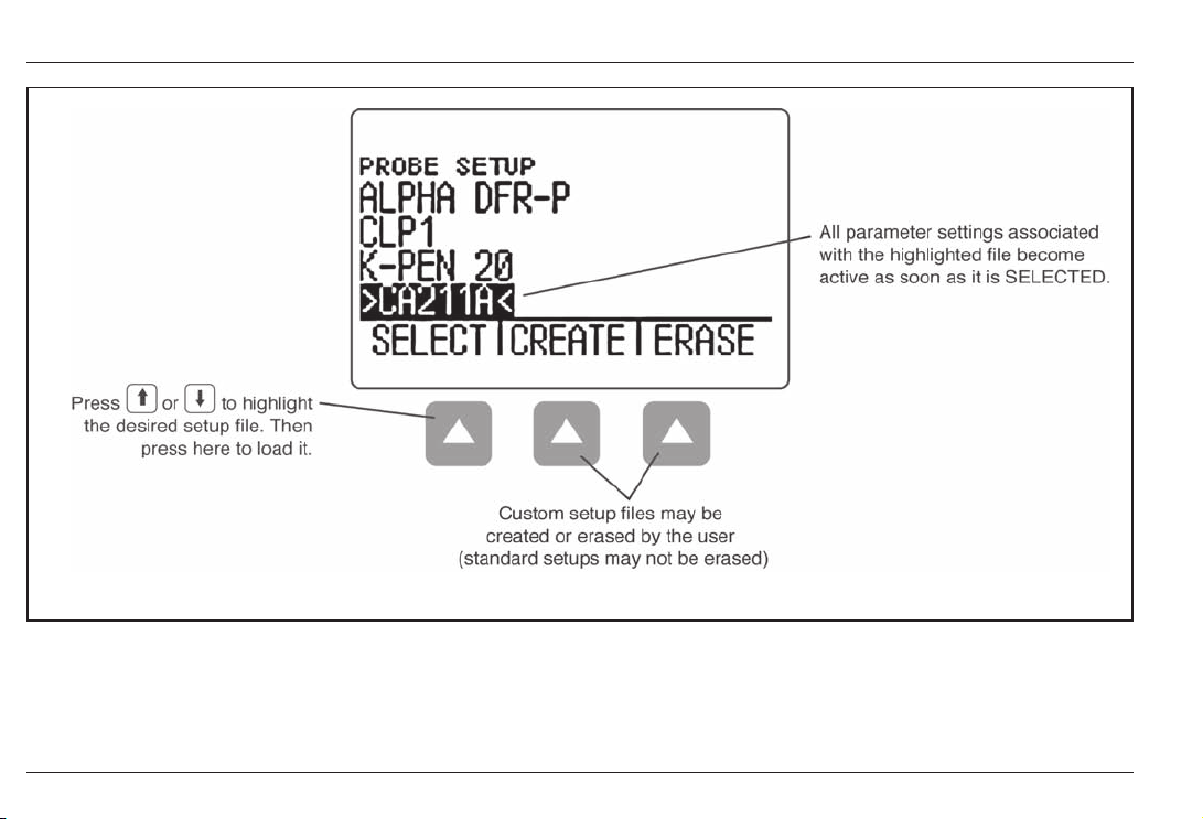
Connecting a Probe and Loading a Setup File
Setting Up the CL 5
3.1 Connecting a Probe and
Loading a Setup File
Prior to measuring thickness, you must connect a
probe to the instrument and select a setup file thats
compatible with the probe (Figure 3-1). The CL 5
supports delay line and contact probe types (see
Chapter 7 for specifications).
Once a probe is connected, press to activate the
Probe Setup display. The Probe Setup display, which is
shown in Figure 3-2, allows the user to select a
standard or Custom Setup file (see Section 3.5 to
create or erase Custom Setup files).
FIGURE 3-1Connecting a Probe Cable
Page 32

3-4 Issue 01, 04/05 CL 5
The following instrument settings are automatically
adjusted when the Setup file is activated:
Custom Setup Filename
Source Setup Filename
View Mode
Gain
Measured Value display resolution
Measurement Mode
Nominal Thickness when Differential, %RR, or
Velocity modes are selected
Minimum Alarm Setting
Maximum Alarm Setting
Zero Offset for contact probes only
Velocity
. Note:
While Custom Setups can be created in any
instrument, the parameter settings, which may be
modified and then saved in a Custom Setup, depend
on the instruments configuration. In a base model
instrument, only the setup name, material velocity
value (determined via calibration), alarm thickness
values, and UT settings related to the probe setup can
be modified and stored in a custom setup.
Setting Up the CL 5 Configuring the Instruments Display
Page 33

CL 5 Issue 01, 04/05 3-5
Configuring the Instruments Display
Setting Up the CL 5
FIGURE 3-2Selecting a Setup File
Page 34

3-6 Issue 01, 04/05 CL 5
3.2 Configuring the Instrument
Prior to using the CL 5 to measure thickness, some or
all of the following parameters must be specified using
the Configuration display shown in Figure 3-3.
Language Set the displayed language to English,
German, French, Spanish, Italian, etc.
Units Set the unit of measurement to inches or
millimeters
Resolution Sets the number of decimal places to
which thickness measurements are displayed
Update Rate Update the displayed measurement
at a rate of 4 or 8 Hz
Radix Select a period (.) or comma (,) to be used
as a decimal point
Battery Type Select from Alkaline, NiCAD, or NiMH
Auto Power Down Select ON to automatically turn
the instrument off five minutes after the last key
press (no data will be lost) or OFF to allow the
instrument to remain on until manually powered off.
Contrast Adjusts the display contrast
Backlight Adjusts the display lighting (a setting of
ON increases battery usage, a setting of AUTO
causes backlighting to illuminate and remain on for
Five Seconds after each key press.)
Each of these parameters is set the same way:
Step 1: Press
multiple times to access the display
(shown in Figure 3-3).
Step 2: Press
or to select each parameter you
would like to modify.
Step 3: When the desired parameter is highlighted,
press
to activate it.
Setting Up the CL 5 Configuring the Instruments Display
Page 35

CL 5 Issue 01, 04/05 3-7
Configuring the Instruments Display
Setting Up the CL 5
FIGURE 3-3Changing Parameter Settings
Page 36

3-8 Issue 01, 04/05 CL 5
Step 4: Press or to adjust the parameters value.
Step 5: Press
when the parameter is set to the
desired value.
Step 6: Continue selecting other parameters for
modification as outlined in Steps 2 through 5. When
complete with all modifications, press to return to
the measurement display.
3.2.1 Setting Instrument Gain
Instrument gain level is set to either a DEFAULT value
or to a noise-reducing LOW setting. To select the
instrument gain setting:
Step 1: Press
Step 2: Select the GAIN control
Step 3: Press
to activate the control, then or
to adjust the setting.
Step 4: Press when the adjustment is complete.
3.2.2 Setting Update Rate
Measurements are updated at a rate of 4 or 8 Hz, as
selected by the user. To select the measurement
update rate:
Step 1: Press
Step 2: Select the UPDATE RATE control
Step 3: Press to activate the control, then or
to adjust the setting.
Step 4: Press
when the adjustment is complete.
3.2.3 Specifying Nominal Thickness
When the VIEW parameter is set to DIFF/RR%, the
displayed thickness includes two differential values (in
the instruments units and as a percentage) that
represent the variation from user-specified nominal
thickness (Section 4.4). Nominal thickness is also
Setting Up the CL 5 Instrument Calibration
Page 37

CL 5 Issue 01, 04/05 3-9
Instrument Calibration
Setting Up the CL 5
used to calculate material velocity when the velocity
measurement option is installed. In VELOCITY view
mode, nominal thickness can be manually input or
directly measured using a connected digital micrometer
(Section 4.6). To manually input or modify the nominal
thickness:
Step 1: Press
Step 2: Select the NOM THICKNESS control
Step 3: Press
to activate the control, then or
to adjust the selected place value and or to
select another value.
Step 4: Press
when the adjustment is complete.
3.3 Instrument Calibration
Before measuring thickness with the CL 5, the
instrument and connected probe must be calibrated.
Its important that the setup file corresponding to the
attached probe be selected prior to launching the
calibration process.
Calibration requires the use of one or more standards
of known thickness. When a contact probe is installed,
either a one or two point calibration can be specified.
Note that contact probe types require zeroing and the
zeroing process is automatically accomplished as part
of calibration. To calibrate the instrument, follow the
instructions in Figure 3-4 and on your instruments
display screen.
. Note:
Proper calibration affects the accurate operation of the
instrument. The instrument should be calibrated if there
is a change in the type or temperature of the material
being tested, if the attached probe is changed, after
performing any parameter adjustment, or at intervals
specified in your test procedures.
3.4 Setting the Maximum and
Minimum Alarms
The CL 5 is equipped with a red LED (at the bottom
center of the instruments key pad) that illuminates
whenever the user-inputted minimum or maximum
Page 38

3-10 Issue 01, 04/05 CL 5
Setting Up the CL 5 Setting the Maximum and Minimum Thickness Alarms
FIGURE 3-4Instrument Calibration Procedure
Page 39

CL 5 Issue 01, 04/05 3-11
Creating and Erasing Custom Setup Files
Setting Up the CL 5
alarm is violated. Note that the inputted alarm value
will correspond to a thickness except when the
VELOCITY measurement option is installed and
activated. In this case the alarm settings will represent
velocity values. To input a minimum or maximum
alarm:
Step 1: Press to access the Configuration display
(shown in Figure 3-3).
Step 2: Press or to select
MINIMUM ALARM or MAXIMUM ALARM
Step 3: When the desired parameter is highlighted,
press
to activate it.
Step 4: Press or to change the selected position
in the alarm thickness and
or to adjust the value
of the selected position. To switch the alarm setting to
OFF from any other value, simultaneously press
and .
Step 5: Press
when the alarm thickness is set to
the desired value.
3.5 Creating and Erasing Custom
Setup Files
After loading a Standard Setup and performing the
necessary adjustments to optimize performance for a
given application, the instrument settings can be
stored and named as a Custom Setup file. The
instrument is capable of storing up to 5 Custom Setup
files, which can be erased at any time
(Figure 3-5).
Custom Setups can be created from any CL 5 keypad.
Custom Setups created using a base-model instrument
include the following settings:
User-assigned Custom Setup file name
VELOCITY
Page 40

3-12 Issue 01, 04/05 CL 5
Setting Up the CL 5 Locking and Unlocking Instrument Controls
FIGURE 3-5Follow this procedure to create or erase a Custom Setup file. Custom Setup file names may contain up
to 16 characters.
Page 41

CL 5 Issue 01, 04/05 3-13
Locking and Unlocking Instrument Controls
Setting Up the CL 5
MINIMUM ALARM
MAXIMUM ALARM
Custom Setups created using instruments equipped
with an optional A-Scan display store the same
parameters as a base-model unit as well as settings
that affect measurement. A full listing of parameter
settings stored in Custom Setup files is found in
Table 3-1.
Tab le 3-1
CUSTOM SETUP FILE CONTENTS
Custom Setup File Name Nominal Thicknesswhen differential, %RR, or Velocity
mode is selected
Source Setup File Name Minimum Alarm Thickness
Gain Maximum Alarm Thickness
Resolution of Displayed Values Zero Offset
View Mode Velocity
Measurement Mode
Whenever a Standard or Custom Setup file is recalled,
all of the instrument settings revert to those settings
stored in the file. Note that thickness measurements
are part of Data Recorder files (see Chapter 5) and are
not stored in Setup files.
. Note:
UltraMATE can be used to transfer Custom Setup files
to a PC where they are stored. The stored Setup file
can then be downloaded to any CL 5.
Page 42

3-14 Issue 01, 04/05 CL 5
3.6 Locking and Unlocking
Instrument Controls
Any instrument function can be made nonoperational
(locked) using the lockout display. Note that this
display is only accessible from the measurement
screen. Follow the instructions in Figure 3-6 to access
this display and lockout (or enable) some or all
function keys.
Setting Up the CL 5 Locking and Unlocking Instrument Controls
Page 43

CL 5 Issue 01, 04/05 3-15
FIGURE 3-6Procedure for locking and unlocking function keys
Locking and Unlocking Instrument Controls Setting Up the CL 5
Page 44

3-16 Issue 01, 04/05 CL 5
Setting Up the CL 5 Locking and Unlocking Instrument Controls
THIS PAGE LEFT INTENTIONALLY BLANK.
Page 45

CL 5 Issue 01, 04/05 4-1
Measuring Thickness 4
Page 46

4-2 Issue 01, 04/05 CL 5
Measuring Thickness Selecting the Displayed View
After setting up the instrument, as described in
Chapter 3, additional adjustments can be made to
select the type of measurement made and the way in
which it is displayed. In this chapter, youll also find
information related to configuring and working with the
optional A-Scan display including how to:
Select the measured value to view (Section 4.1)
Work with Normal measurement mode (Section 4.2)
Use the Min Scan and Max Scan measurement
modes (Section 4.3)
Interpret the Differential/Rate-of-Reduction
measurement mode (Section 4.4)
Work with the optional Thickness + A-Scan
measurement mode (Section 4.5)
Use the optional Velocity measurement mode
(Section 4.6)
. Note:
Load a Setup file corresponding to the connected probe
prior to making the adjustments described in this
chapter. Loading a Setup file after these adjustments
are made will force certain settings back to the default
value stored in the file.
. Note:
After making some or all of the adjustments described
in this chapter, the modified instrument setup can be
stored by creating a Custom Setup file. Your instrument
will store up to 5 Custom Setup files, which are
created (and erased) via the setup display. See
Section 3.5 for step-by-step instructions to create a
Custom Setup file.
4.1 Selecting the Displayed View
The measurement displayed by the instrument is
modified by
Step 1: Press multiple times to access the
configuration menu
Page 47

CL 5 Issue 01, 04/05 4-3
Step 2: Press or to select the VIEW MODE
parameter
Step 3: Press
to activate this parameter
Step 4: Scroll through the available modes by pressing
or . Press to select the displayed mode
(described below).
Base model instruments offer four display modes. In
addition, two more display modes are available
depending on the installed options. Display modes
include:
NORMAL (Thickness Only) The thickness value
appears as large digits in the center of the display. No
live A-Scan is displayed but an A-Scan snapshot of
the triggering echo can be accessed (Section 4.2).
MIN SCAN (Minimum Thickness Scan) Allows the
user to continuously evaluate material thickness
(provided the probe remains coupled or is uncoupled
only briefly) then, when the evaluation period is
complete, the minimum material thickness is
displayed. During the evaluation period, thickness is
displayed along with the minimum and maximum
observed thickness values (and the calculated
difference between the two). The display also includes
a time-out bar, which begins to fill as soon as the
probe is uncoupled. Recoupling the probe before the
time-out period expires allows the user to continue with
the same evaluation period. When the evaluation period
is complete (after the probe is uncoupled and the timeout bar fills), the minimum thickness observed during
the evaluation period is displayed. Its corresponding AScan can also be displayed by pressing
. At this
point the screen is frozen. Recouple the probe to
reactivate the display screen (Section 4.3).
MAX SCAN (Maximum Thickness Scan) Allows the
user to continuously evaluate material thickness
(provided the probe remains coupled or is uncoupled
only briefly) then, when the evaluation period is
complete, the maximum material thickness is
displayed. During the evaluation period, thickness is
displayed along with the minimum and maximum
observed thickness values (and the calculated
difference between the two). The display also includes
a time-out bar, which begins to fill as soon as the
probe is uncoupled. Recoupling the probe before the
time-out period expires allows the user to continue with
Measuring Thickness
Selecting the Displayed View
Page 48

4-4 Issue 01, 04/05 CL 5
the same evaluation period. When the evaluation period
is complete (after the probe is uncoupled and the timeout bar fills), the maximum thickness observed during
the evaluation period is displayed. Its corresponding AScan can also be displayed by pressing
. At this
point the screen is frozen. Recouple the probe to
reactivate the display screen (Section 4.3).
. Note:
During the placement of a very sensitive probe on the
part surface, excess couplant may cause erroneous
results. To eliminate the effect of excessive couplant,
couple the probe firmly to the part, then press
under
the ASCAN function, then press
under HOME.
This restarts the scanning session while the probe is
properly in contact with the part.
DIFF / RR% (Differential / Rate-of-Reduction) The
currently measured and user-inputted nominal
thickness appear along the top of the display while the
difference between these two values (measured minus
nominal values expressed in percentage and
dimensional terms) appears in the middle of the
display. Note that the displayed differences can have
positive or negative values (Section 4.4).
THK + A-SCAN (Thickness and A-Scan) An A-Scan
appears in the center portion of the display and the
thickness value is shown in the displays upper righthand corner (Section 4.5).
VELOCITY (Material Velocity) The material velocity
value appears as large digits in the center of the
display. This velocity calculation requires an accurate
NOMINAL THICKNESS value which can be inputted by
the user or by using the connected digital caliper. Note
that no live A-Scan is displayed but an A-Scan
snapshot of the triggering echo can be accessed
(Section 4.6).
4.2 Normal Measurement Mode
(No Live A-Scan)
When NORMAL view mode is active, the display only
contains a thickness reading (see Section 4.1 to select
view mode). While no live A-Scan is available, an AScan Snapshot can be accessed at any time by
pressing
directly below A-SCAN on the function bar
(Figure 4-1).
Measuring Thickness Normal Measurement Mode
Page 49

CL 5 Issue 01, 04/05 4-5
FIGURE 4-1NORMAL view mode displays only the thickness reading. Selecting the A-SCAN function bar option
allows you to view a Snapshot of the A-Scan echo that is represented by the thickness reading. This A-Scan is frozen.
No live A-Scan echo is available in this view mode.
Measuring Thickness
Normal Measurement Mode
Page 50

4-6 Issue 01, 04/05 CL 5
4.3 Min Scan and Max Scan
Measurement Modes
These modes allow the user to continuously evaluate
material thickness then, when the evaluation period is
complete, display the extreme (minimum or maximum)
material thickness observed. During the evaluation
period, thickness is displayed along with the minimum
and maximum observed thickness values (Figure 4-2).
See Section 4.1 to select view mode.
FIGURE 4-2MIN SCAN and MAX SCAN views allow the user to observe thickness measurements over an area, and
display the maximum and minimum thickness encountered during the evaluation period. The time-out feature
(represented by the bar shown here) allows the user to momentarily uncouple during the evaluation period, and then
recouple to continue the same period. In these modes the instrument will continue to collect and compare thickness
readings for as long as the probe remains coupled.
Measuring Thickness Min Scan and Max Scan Measurement Modes
Page 51

CL 5 Issue 01, 04/05 4-7
4.4 Differential / Rate-ofReduction Measurement
Mode
This view mode displays the currently measured and
user-inputted nominal thickness, along with the
difference between these two values (measured minus
nominal) expressed in percentage and dimensional
terms. Note that the displayed differences can have
positive or negative values (Figure 4-3). See Section
4.1 to select view mode and 3.2.3 to specify
nominal thickness.
Measuring Thickness
Differential/Rate-of-Reduction Measurement Mode
FIGURE 4-3The DIFF / RR% view compares the live measurement with a user-inputted nominal material thickness.
This comparison is then expressed as a differential measurement and a percentage of the nominal thickness.
Page 52

4-8 Issue 01, 04/05 CL 5
4.5 Thickness + A-Scan
Measurement Mode (Optional)
This optional view mode displays both a live A-Scan
reading and corresponding thickness value. Selecting
FIND moves the triggering echo to the center of the
display while FREEZE captures the live A-Scan. After
the display is frozen, select ZOOM to magnify the
triggering echo (Figure 4-4). See Section 4.1 to select
view mode.
FIGURE 4-4THK + A-SCAN view mode displays, freezes, and magnifies a live A-Scan.
Measuring Thickness Thickness + A-Scan Measurement Mode
Page 53

CL 5 Issue 01, 04/05 4-9
4.6 Velocity Measurement Mode
(Optional)
This optional view mode displays measured material
velocity (see Section 4.1 to select view mode). The
material velocity calculation depends on the value
inputted for the test materials nominal thickness. This
nominal thickness value can be manually inputted
(Section 3.2.3) or by using the digital caliper supplied
with all instruments that incorporate the Velocity option.
(Figures 4-5 and 4-6). Note that when operating in
VELOCITY view mode, material velocity values may
be entered for MINIMUM and MAXIMUM ALARMs
(Section 3.4).
FIGURE 4-5VELOCITY view mode allows measurement of acoustic velocity based on a user inputted (or manually
measured) mechanical thickness.
Measuring Thickness
Velocity Measurement Mode
Page 54

4-10 Issue 01, 04/05 CL 5
Measuring Thickness Velocity Measurement Mode
FIGURE 4-6Direct input of nominal thickness in VELOCITY mode.
Page 55

CL 5 Issue 01, 04/05 5-1
Using the Optional Data Recorder 5
Page 56

5-2 Issue 01, 04/05 CL 5
Using the Optional Data Recorder Creating a New Data Recorder File
. Note:
The instructions here apply only to instruments
equipped with a Data Recorder.
When installed and activated, the data recorder option
allows users to create Data Recorder files, store
thickness readings (and accompanying A-Scans when
desired), and navigate through file contents. In this
chapter youll learn how to
Create Data Recorder files (Section 5.1)
Recall and erase Data Recorder files (Section 5.2)
Store thickness readings in Data Recorder files
(Section 5.3)
Store A-Scans in Data Recorder files (Section 5.3.1)
Navigate Data Recorder file locations to store or
delete readings (Section 5.3.2)
Print reports (Section 5.4)
5.1 Creating a New Data Recorder
File
To create a new Data Recorder file, you need only
specify a file name. In most cases, however, youll
wish to enter additional information. Parameters that
can be adjusted during the file-naming process include:
The first (TOP) and last (BOTTOM) positions in the
Data Recorder file (Figure 5-2 describes how these
define the number of locations in the new file)
The ADVANCE DIRECTION (described in
Figure 5-2)
NOTES related to the data file
Follow Steps 1 through 5 in Figure 5-1 to create a new
Data Recorder file.
. Note:
Once created, the file name and size parameters can
NOT be edited. Only the ADVANCE DIRECTION
parameter and NOTES contents can be modified. To
accomplish this, first select the file then activate and
modify the parameter.
Page 57

CL 5 Issue 01, 04/05 5-3
Creating a New Data Recorder File
Using the Optional Data Recorder
FIGURE 5-1Creating a New Data Recorder File
Page 58

5-4 Issue 01, 04/05 CL 5
5.2 Recalling and Erasing Stored
Data Recorder Files
Stored files can be recalled or erased at any time.
Once recalled, thickness measurements can be stored
in empty file locations, existing measurements can be
deleted and the advance direction can be changed. To
recall a Data Recorder file:
Step 1: Press
to access the CONFIGURATION
display, then set DATA RECORDER to ON.
Step 2: Press
again to launch the File Display
mode
Step 3: Activate the file selection function by pressing
below FILES. A file list will appear on the display.
Using the Optional Data Recorder Recalling and Erasing Stored Data Recorder Files
FIGURE 5-2Defining the Size and Advance Direction of a Data Recorder File
Page 59

CL 5 Issue 01, 04/05 5-5
Step 4: Press or to select the stored file you
wish to recall, and then press
.
To erase a Data Recorder file:
Step 1: Press
to launch the File Display mode
Step 2: If required, press
below FILES to obtain a
list of stored files.
Step 3: Press or to select the stored file you
wish to erase, and then press and hold below
ERASE.
. Note:
Once erased, the Data Recorder file and any stored
thickness measurements can not be retrieved.
5.3 Recording Thickness and
Velocity Measurements in
Data Recorder Files
The Data Recorder must be enabled (turned ON) via
the CONFIGURATION display. Once the Data Recorder
is turned on, the contents of the active Data Recorder
file are displayed in the File Navigation Grid shown in
Figure 5-2.
To store a thickness reading in the selected file
position, press
below SEND. Remember that the
units of the thickness value, and the number of
decimal places to which the thickness is recorded, are
determined by the UNITS and RESOLUTION settings
as described in Section 3.2.
. Note:
Pressing and holding below SEND for three
seconds will cause the thickness and displayed AScan to be stored in the selected position as described
in Section 5.3.1.
Recording Thickness Measurements in Data Recorder Files Using the Optional Data Recorder
Page 60

5-6 Issue 01, 04/05 CL 5
. Note:
Pressing
below SEND with the instrument
connected to a PC that has the applicable software
installed and running will result in the thickness reading
being sent out the I/O port as described in Section 6.1.
5.3.1 Recording A-Scans in Data
Recorder Files
An A-Scan can be stored in that active position of the
Data Recorder by pressing and holding (for three
seconds)
below SEND.
5.3.2 Navigating Through Data Recorder
Files
When the Data Recorder is turned on, the contents of
the active Data Recorder file are displayed in the
File Navigation Grid shown in Figure 5-2. Once the
navigation grid is activated,
, , , and can be
used to select any file position. Note that a heavier grid
box appears around the selected file position. Once a
file position is selected:
The current thickness reading can be sent to an
EMPTY file position
A measurement value can be stored by pressing
below SEND
An already stored value can be deleted by pressing
below CLEAR
5.4 Printing a Report
. Note:
The following procedure explains how to print the
contents of a stored Data Recorder file.
Once the instrument is configured for the connected
PC (see Section 6.2), you can proceed with the report
printing process. A printed report will include:
Printing a Report Using the Optional Data Recorder
Page 61

CL 5 Issue 01, 04/05 5-7
A file header listing Data Recorder file name
A description of the files structure including number
of rows, columns, and a listing of NOTES
All thickness measurements stored in the Data
Recorder file, along with an indication if the file has
an A-Scan attached or resulted from a Minimum or
Maximum thickness scanning session.
Attached A-Scans are NOT printed as part of the
report
Step 1: Press to access the Data Recorder file
display as shown in Figure 5-2.
Step 2: Follow the regular procedure to select the file
to be printed.
Step 3: Press
below PRINT to launch the report
printing process. All features listed above will be
included in the printed report.
Using the Optional Data Recorder Printing a Report
Page 62

5-8 Issue 01, 04/05 CL 5
Printing a Report
Using the Optional Data Recorder
THIS PAGE LEFT INTENTIONALLY BLANK.
Page 63

CL 5 Issue 01, 04/05 6-1
I/O Features 6
Page 64

6-2 Issue 01, 04/05 CL 5
I/O Features Transmitting Thickness Data Through an External Device
. Note:
The instructions in this chapter apply to all
instruments.
The instrument can communicate with external devices
in several ways. All of these communication methods
rely on the instruments I/O port. The following cables
are available for connection to this RS-232 port (see
Figure 3-1 for location):
USB PC Cable
Serial PC Cable
Digital CaliperVelocity Option
Li Battery Packs Charging cable
The instrument determines if the cable is connected to
a device provided the device is not off line or busy.
Individual thickness readings and A-Scans can be
transmitted to an attached device. With the use of
remote codes, a PC can control the instrument.
In this chapter you will find:
The byte structure used when thickness readings
are transmitted through the I/O port (Section 6.1)
Remote commands (Section 6.2)
6.1 Transmitting Data to an
External Device
When below SEND is pressed to transmit a
thickness or velocity value through the I/O port, data
will be transmitted at 8 data bits, 1 stop bit, no parity,
and at the user-specified baud rate. The transmitted
data will be in a 13-byte message format, structured as
shown in Table 6-1. Note that data can be transmitted
(and SEND appears) only when the PC cable is
connected to a device that can receive data.
Page 65

CL 5 Issue 01, 04/05 6-3
Transmitting Thickness Data Through an External Device
I/O Features
Table 6-1
Format of Transmitted Thickness Measurements
Byte 1 "+" or "-" for displayed differential thickness values
"?" for displayed high resolution metric velocity values
" " (space) for all other di splayed values
Byte 2,3,4,5,6 Display value (4 digits and decimal point)
.0000
0.000
00.00
000.0
0000.
Byte 7 " " (space)
Byte 8,9,10,11 "IN " for displayed inch thickness values
"MM " for displayed metric thickness values
Byte 12 Carriage Return (ASCII 13)
Page 66

6-4 Issue 01, 04/05 CL 5
6.2 Setting Communication
Speed (Baud Rate) and
Connecting to a PC
Using the proper cable, the instruments I/O port can
be connected to a PC. Before connecting to a PC do
the following:
Step 1: Press
to display the CONFIGURATION
menu
Step 2: Select the COMM (communication) control
Step 3: Press
to activate the control, then or
to adjust the selected baud rate to match that of the
connected device. Data transfer will not occur if the
selected baud rate does not match the device.
Step 4: Press
when the desired value is selected.
6.3 Remote Commands
The CL 5 can receive coded instructions from a
personal computer or terminal connected to the RS-232
I/O Features Setting Communication Speed and Type
I/O port. Queries, key presses and adjusting
instrument settings can be done remotely by using a
user written program or a commercially available serial
communications program such as Windows
HyperTerminal. After starting and configuring the
program, commands are inputted using the computer
keyboard.
Two types of command structures are possible:
To request the status or value of a function the
following sequence is used:
<ESC><COMMAND><RETURN>
To execute a keypad operation or adjust a setting
the following sequence is used:
<ESC><COMMAND><SPACE><VALUE><RETURN>
Examples:
<ESC><8J><RETURN>
The CL 5 will now return the version of
instrument operating software.
Page 67

CL 5 Issue 01, 04/05 6-5
Setting Communication Speed and Type
I/O Features
<ESC><7K><SPACE><11><RETURN>
The CL 5 now displays the Setup Screen
listing all stored default and custom probe
setups.
Remote Control Codes:
The following is a partial listing of remote commands.
Additional remote commands are available upon
request.
Strings inside [ ] are values / parameters
Codes supporting queries are indicated with *
Page 68

6-6 Issue 01, 04/05 CL 5
I/O Features
Setting Communication Speed and Type
edoCyreuQretemaraPegnaRnoituloseRnoitcnuF
*DI).qerton(seY ."5LC"snruterTNEMURTSNI:noitacifitnedI
*PD).qerton(seY fotsilanruterlliwTNEMURTSNI:steSretemaraPfoyrotceriD
elifehtsatamrofemasehtni)sputesmotsuc(stesretemarap
:erutcurtsyrotcerid
XXXXXXXXXXXXXXXX1000
XXXXXXXXXXXXXXXX2000
XXXXXXXXXXXXXXXX3000
XXXXXXXXXXXXXXXX4000
*RD).qerton(seY htiwselifredroceratadfotsilanruterlliwTNEMURTSNI:yrotceriD
42sis'Xybdetacidnidleifemanelif(noitamrofniepytelif
:)sretcarahc
).delbanesinoitporedroceRataDnehwdetroppusylno(
DIRGXXXXXXXXXXXXXXXX1000
NIILCXXXXXXXXXXXXXXXX2000
)n(XFONrebmunelif
tsilridno
ot1
forebmuN
selif
1 ebdluohs)n(.)n(ybdetacidnielifehttimsnartlliwTNEMURTSNI
.tsilyrotceridehtnodeyalpsidsarebmunelifeht
).delbanesinoitporedroceRataDnehwdetroppusylno(
UF sihT.edomeviecerelifotnioglliwTNEMURTSNI:daolpUeliF
.stesretemaraprofdesuebtondluohs
).delbanesinoitporedroceRataDnehwdetroppusylno(
]n[UPretemaraP
rebmuntes
11ot1
no7ot1(
)P5LC
1 tesretemarapotnioglliwTNEMURTSNI:daolpUteSretemaraP
ottesretemaraphcihwsetacidni]n[retemarapehT.edomeviecer
.dedaolpuenoehthtiwecalper
)deunitnoC(
Page 69

CL 5 Issue 01, 04/05 6-7
edoCyreuQretemaraPegnaRnoituloseRnoitcnuF
]n[DPONretemaraP
rebmuntes
11ot0
no7ot0(
)P5LC
tesretemarapotnioglliwTNEMURTSNI:daolnwoDteSretemaraP
setacidni]n[.tesretemarapdetseuqerehtgnidnesedomdaolnwod
.detseuqersitahtrebmuntesretemarapeht
.sretemaraptnemurtsnievitcayltneserpehtsdnes0
MA noelbaliavayromemnruterlliwTNEMURTSNI:yromeMelbaliavA
.setybnidracDS
]rts[PAONputeS
emaN
.deificepsemangnirtsretemarapehtybdetacidniputesehtsdaoL
]n[FASEYrebmunelif
tsilridno
rebmunot1
seliffo
1.elifredroceratadevitcaehtyreuQ/teS:eliFevitcA
]n[K7ONsserpyek
edoc
1.etucexeotsserpyektahwdetacidnieulav=]n[:sserPyeK
0YEK_ON_EDOCKenifed#
11F_EDOCKenifed#
22F_EDOCKenifed#
33F_EDOCKenifed#
4WORRA_PU_EDOCKenifed#
5WORRA_NWOD_EDOCKenifed#
6WORRA_TFEL_EDOCKenifed#
7WORRA_THGIR_EDOCKenifed#
8EDOM_EDOCKenifed#
9FFO_NO_EDOCKenifed#
H7ON .edomweivtnemerusaemGTottnemurtsnisteS:EMOH
)deunitnoC(
Setting Communication Speed and Type
I/O Features
Page 70

6-8 Issue 01, 04/05 CL 5
I/O Features Setting Communication Speed and Type
edoCyreuQretemaraPegnaRnoituloseRnoitcnuF
R7ON riehtotsretemarapgniwollofehtsteseR.teserretemaraptfoS
:stluafed
ssenkcihT:edoMweiV
DOIREP:xidaR
FFO:thgilkcaB
hsilgnE:egaugnaL
)detcetedsiyrettabiLsselnu(enilaklA:seirettaB
otuA:nwoDrewoP
HCNI:stinU
XXX.X:noituloseR
)sretemaraptuokcollla(FFO:stuOkcoL
000.0:ssenkcihTlanimoN
)FFO(000.0:smralAxaM/niM
)detceffa-ton(etarduaB
J8)qerton(SEY rebmunnoisrevmetsySgnitarepOrofyreuQ
K8)qerton(SEY rebmuNlaireStnemurtsnIrofyreuQ
M8 .gnirtsnoisiveredoctooBrofyreuQ
N8 .gnirtsnoisiverngisedAGPFrofyreuQ
T8)qerton(SEY .erutarepmettnemurtsnilanretnirofyreuQ
Y8ONDCL
yromeM
pmuD
niyromemyalpsidDCLehtfopamtibehtgniniatnocatadpmudlliW
.stamroflarevesfoeno
rofetybyromemoedivehtspmudsihT.pmudyranibehtsisihT
.etyb
)deunitnoC(
Page 71

CL 5 Issue 01, 04/05 6-9
Setting Communication Speed and Type
I/O Features
edoCyreuQretemaraPegnaRnoituloseRnoitcnuF
C9ONenon edomnoitarugifnoc/noitarbilacyrotcafotnitnemurtsnisecalP
D9ONenon daolnwoD.edomnoitarugifnoc/noitarbilacyrotcafnielihwylnoevitcA
ehT.tnemurtsniehtmorfatadnoitarbilacevitcayltneserpeht
ecapsnoitarbilacehtfosetyb652gnidnesybdnopserlliwtnemurtsni
.enohcaeretfaRCahtiwtamrofrebmunlamicedni
U9ONenon daolpU.edomnoitarugifnoc/noitarbilacyrotcafnielihwylnoevitcA
ottcepxelliwtnemurtsniehT.tnemurtsniehtotecapsnoitarbilaceht
ehT.hcaeretfaRCahtiwecapsnoitarugifnocfosetyb652eviecer
.dessecorpsietybhcaeretfaRCahtiwdnopserlliwtnemurtsni
P9ONresluP
elbasid
selbasiD.edomnoitarugifnoc/noitarbilacyrotcafnielihwylnoevitcA
.snoitarblacniagrofreslup
elbane-0
elbasid-1
A9ONenon MORPEEotnikcabecapsnoitarbilacdetadpumargorP
SMSEY :sutatselpuoc,yticolev,ssenkcihttnemurtsnitneserpehtrofyreuQ
)sdleifdetimiledammoc(:tamroFtuptuO
sutatselpuoc,yticoleV,ssenkcihT
.noitulosermm100.nirebmunelohwaebsyawlalliwssenkcihT
.s/m1.0nieblliwyticoleV
delpuocnurof"U",delpuocrof"C"eblliwgalfelpuoC
)deunitnoC(
Page 72

6-10 Issue 01, 04/05 CL 5
I/O Features Setting Communication Speed and Type
edoCyreuQretemaraPegnaRnoituloseRnoitcnuF
W8ONgnimaertS
edoMataD
1
2
3
4
5
edomanitnemurtsniehttuplliw)0(fforo)x(noedomsihtgninruT
retfaTRAUehtrevodneseblliwFOTdnaeulavssenkcihtehterehw
duabwolstanwodtnemurtsniehtwolsyamsihT.noitisiuqcahcae
.edompaC-niMnigninnurnehwrosetar
)sdleifdetimiledammoc(:tamroFtuptuO
SUTATSELPUOC,YTICOLEV,SSENKCIHT
.noitulosermm100.nirebmunelohwaebsyawlalliwssenkcihT
noitulosers/m1nideyalpsidyticoleV
delpuocnurof"U",delpuocrof"C"eblliwgalfelpuoC
SUTATSELPUOC,SUTATSMRALA,SSENKCIHT
:sadeyalpsidsimralA
mralaon:Ñ)nofi(mralanimnahtsselsissenkciht:<
)nofi(mralaxamnahtretaergsissenkciht:>
SUTATSELPUOC,FOT
sdnoces-onanninoituloserthgilffoemiT
SUTATSELPUOC,%RR,ECNEREFFID,SSENKCIHT
ssenkcihtlanimonmorfdetaluclacsiecnereffiD
ssenkcihtlanimonmorfecnereffidegatnecrepehtsi%RR
SUTATSELPUOC,KCIHTXAM,KCIHTNIM,SSENKCIHT
noitulosermm100.ni,seulavssenkcihtehterassenkcihtxamdnaniM
ngis-ehtsadeyalpsideblliwxaMdnaniM.noisseserutpacehtrof
sahxamronimwenondnadetratssinoisseserutpacwenanehw
.derutpacneeb
RTONssenkcihT
yalpsiD
noituloseR
xxxx.x-0
xxx.x-1
xx.x-2
x.x-3
noituloseryalpsidssenkcihtsteS
RPONtuokcoL
drowssaP
teseR
otsretemaraptuokcolllastesdna5LCotdrowssaptuokcolehtsteseR
.dekcolnu
Page 73

CL 5 Issue 01, 04/05 7-1
Specifications 7
Page 74

7-2 Issue 01, 04/05 CL 5
Specifications Instrument Specifications
This chapter lists the features and specifications of your CL 5 including:
• Instrument Specifications (Section 7.1)
• Features of the Optional A-Scan (Section 7.2)
• Features of the Velocity Measurement Option (Section 7.3)
• Features of the Optional Data Recorder (Section 7.4)
• Probe Specifications (Section 7.5)
7.1 Instrument Specifications
Operating Principle: Ultrasonic, pulse echo measurement method
Measuring Range: 0.006 to 20.00 inch depending on probe and material
0.16 to 500 mm
Measuring Resolution: inch 0.001 default (selectable 0 .0001, 0.001, 0.01 inch)
mm 0.01 default (selectable 0.001, 0.01, 0.1 mm)
Material Velocity Range: 0.03937 to 0.78736 in/µs
1000 to 19999 m/s
Material Velocity Resolution: 0.00001 in/µs
0.1 m/s
Page 75

CL 5 Issue 01, 04/05 7-3
Instrument Specifications Specifications
Units: Inch or millimeter
Calibration: Enter velocity or thickness
Contact: One point or Two point calibration
Delay: One point
Pulser:
Excitation Pulse: Spike Pulser
Voltage: 100 V into 50 ohm load, using 20 MHz Scope
Receiver
Bandwidth: 1.0 to 10 MHz @ -3 dB
Gain: Automatic Gain Control
Display Type: High Resolution: Graphical LCD 64 x 128 Pixels,
2.25 ´ 2.56 (40 ´ 57 mm) with backlight and adjustable contrast.
Update Rate: 4 Hz or 8 Hz (User Selectable)
Thickness Value Display: 5 digit 0.75 (19 mm) high NORMAL MODE
5 digit 0.25 (6 mm) high with display of A-SCAN)
Page 76

7-4 Issue 01, 04/05 CL 5
Display of Last Reading: Solid filled or hollow digits indicate coupled or uncoupled condition.
Setups: 6 Standard Setups for Contact and Delay probes
5 Custom Setups with up to 16 character alphanumeric name
Alarm Settings: Minimum and Maximum Alarms
Range of 0.005-20 in. (0.1-508 mm)
Red LED illuminates and < or > displayed when alarms are enabled and
violated.
Power Requirements: Standard Li Battery Pack with on-board charger.
Batteries 3 each, AA size Alkaline, NiCad or NiMH
Battery Life/Operating Time: Approximately 24 hours
Instrument Shut-0ff: Selectable ALWAYS ON or AUTO OFF after 3 minutes of inactivity
Language: Selectable English, German, French, Spanish, and Italian
Baud Rate: Selectable 115200, 57600, 9600, 1200
Specifications Instrument Specifications
Page 77

CL 5 Issue 01, 04/05 7-5
I/O Connectors
Transducer: 00 Lemo (coax)
RS-232, Battery Charger: MicroD9 (Female),
Charger 100240 V, 5060 Hz
Temperature
Operating: +10°F to +140°F (-10°C to +60°C)
Storage: -10°F to +160°F (-20°C to +70°C)
Weight: 0.92 lbs. (420 g) including batteries
Size: 7.1 H x 3.7 W x 1.8 D (180 mm x 94 mm x 46 mm)
Instrument specifications subject to change without prior notice.
7.2 A-Scan Option Parameter Adjustments
Display View Thickness + A-Scan
Instrument specifications subject to change without prior notice.
7.3 Velocity Measurement Option Features
Display View VELOCITY Measurement
A-Scan Option Parameter Adjustments Specifications
Page 78

7-6 Issue 01, 04/05 CL 5
7.4 Data Recorder Option Features
Capacity: 120 files each containing 10,000 readings with or without A-Scan
attachments (May vary based on size of SD card used.)
File Structures Grid created from instrument keypad and Custom Linear created with
UltraMATE
File Naming: Up to 24 character alphanumeric name
Optional Software: UltraMATE and UltraMATE Lite
Instrument specifications subject to change without prior notice.
7.5 CL 5 Probe/Transducer Specifications
Model Probe Nominal Contact Measuring
Type Freq. Diameter Range
A-2 DFR & CLF4 Standard Delay Line 15 MHz 0.30 in. 0.007 to 1.0 in.
7.6 mm 0.18 to 25.4 mm Steel
Specifications Data Recorder Option Features
Page 79

CL 5 Issue 01, 04/05 7-7
Model Probe Nominal Contact Measuring
Type Freq. Diameter Range
Alpha 2F & CLF5 Fingertip Contact 10 MHz 0.38 in. 0.060 to 10.0 in.
9.5 mm 1.52 to 254 mm
Steel
Alpha DFR-P Plastics, Delay Line 22 MHz 0.30 in. 0.005 to 0.15 in.
7.6 mm 0.13 to 3.8 mm
Plastic
Mini-DFR Thin Range Delay Line 20 MHz 0.19 in. 0.005 to 0.200 in.
4.8 mm 0.13 to 5.1 mm
Steel
CL1P1 Pencil Probe 15 MHz 0.065 or 0.090 in. 0.008 to 0.175 in.
1.7 or 2.3 mm 0.20 to 4.4 mm
Steel
CA211A Standard Contact 5 MHz 0.75 in. 0.060 to 20.0 in.
19.1 mm 1.52 to 508 mm
Steel
Note: Other Probe Models Available upon request
Cl 5 Probe/Transducer Specifications Specifications
Page 80

7-8 Issue 01, 04/05 CL 5
Specifications CL 5 Probe/Transducer Specifications
THIS PAGE WAS INTENTIONALLY LEFT BLANK.
Page 81

CL 5 Issue 01, 04/05 8-1
Maintenance 8
Page 82

8-2 Issue 01, 04/05 CL 5
Maintenance Care of the Instrument
Care of the Instrument
Clean the instrument housing and display using a soft
cloth lightly dampened with water or a mild windowcleaning product. Never use harsh solvents as they
could cause the plastic to become brittle or damaged.
Care of Delay Line Probes
Replace delays showing signs of excessive wear or
those embedded with metal turnings. Delays in good
condition should periodically have the couplant
between the probe face and delay refreshed as follows:
Remove the delay by unthreading the knurled ring
Wipe clean the mating surfaces of the delay and
transducer face
Apply a fresh drop of lightweight oil (recommend
XD-740 couplant) and replace the delay line
Proper Cable Handling
Avoid twisting or knotting of the cable
Grasp the cable only by the connectors when
connecting or disconnecting from the instrument
Batteries
Periodically inspect the batteries for signs of leakage
or corrosion. If either occurs, remove and replace ALL
the batteries. Take care to properly dispose of the
defective batteries.
Page 83

CL 5 Issue 01, 04/05 9-1
Appendix 9
Page 84

9-2 Issue 01, 04/05 CL 5
Appendix Resetting the Operating Software
This section contains supplementary information
including instructions on:
Resetting the Instruments Operating Software
Upgrading the Instruments Software
EMC Documentation
Manufacturing and Service Center Locations
9.1 Resetting the Operating
Software
WARNING: The following procedure deletes all
Custom Setup files stored in the instrument. Any files
you wish to retain should be downloaded using the
UltraMATE PC software before resetting the operating
software. Data recorder files (if so equipped) stored on
the installed SD card will not be deleted.
To reset the instruments operating software:
Step 1: Turn off the instrument.
Step 2: Press and hold down
then press
and hold down . Continue to press both keys for
approximately three (3) seconds until the power-on
sequence is initiated.
Step 3: A successful reset is acknowledged when the
RESET COMPLETE message briefly appears in the
display screens bottom center.
9.2 Upgrading the Operating
Software
The CL 5 operating software can be upgraded using an
internet connection and an upgrade utility program.
Each instrument is shipped with a CD containing the
CL 5 Upgrade Utility Program.
Step 1: Install the Upgrade Utility Program on your
Internet connected PC.
Step 2: Run the program by clicking on the program
icon, located on your Program Menu. (Click the START
and then RUN buttons, select PROGRAMS, and select
CL 5 Upgrade Utility.)
Page 85

CL 5 Issue 01, 04/05 9-3
Step 3: Select the Download New File button.
The program will connect to the GE Inspection
Technologies, FTP site (you may need to be connected
to the Internet prior to this operation). The program
checks the version you have on your machine against
the version that is on the FTP site. If the version on
the FTP site is newer, it will download the CL 5
operation code. If they are the same, it will not
download the program, but exit the download routine.
Step 4: Turn off the CL 5 and connect it to the PC.
Step 5: Click on the Upgrade The Instrument button.
Step 6: WHEN PROMPTED, press and hold the
and for 3 seconds. The CL 5 will go into the reprogramming mode. When finished, the CL 5 will
automatically shut off.
Step 7: Reset the operating software to clean out the
instruments memory (WARNING: All stored Custom
Setup Files will be lost!!! However, stored Data
Recorder files will not be affected).
Information available on the GE Inspection
Technolgies, web site. GEInspectionTechnologies.com
Up to date information on operating software
Latest upgrade utility program
Specifications
New features
Literature
And much more!
9.3 EMC Documentation
The following page displays the CL 5s Declaration of
EMC Compliance.
Upgrading the Operating Software Appendix
Page 86

9-4 Issue 01, 04/05 CL 5
Appendix
EMC Documentation
Engineering Declaration of EMC Compliance
CL 5 Ultrasonic Precision Thickness Gauge
References: Radiation Sciences, Incorporated EMC Test Report No. RSI-2703E, GE Inspection Technologies
Model CL 5, 21 March 2005.
Instrument Description: The CL 5 is a precision ultrasonic thickness gauge capable of measuring materials
using ultrasonic transducers operating in frequency from .6 to 28 MHz. This instrument displayed a thickness
calculated by the measured time of flight in the material at the velocity specified to the instrument. The instrument
is intended for use as a portable thickness gauge in an industrial environment. The instrument is not intended to
be part of a closed control loop in an automated process control system.
Compliance Statement: The CL 5 complies with the following EN standards:
EN 55011: 1998 Radiated and conducted emissions, Class A
EN 61000-3-2: 2001 Harmonic current emissions, Class A
EN 61000-3-3: 1995 Voltage fluctuations and flicker
EN 61000-4-2: 1995 Electrostatic Discharge 2, 4, 8kV
EN 61000-4-3: 1998 Radiated Fields at 10 V/m from 80-1000 MHz including 1.4 to 2.0 GHz
EN 61000-4-4: 1995 Fast Transient/Burst at 2 kV
EN 61000-4-5: 1995 Surge Immunity 0.5 , 1, 2 kV
EN 61000-4-6: 1996 Conducted RF Disturbances 10 V/rms
EN 61000-4-11: Voltage Dips/Interruptions
Page 87

CL 5 Issue 01, 04/05 9-5
Manufacturer/Service Addresses Appendix
9.4 Manufacturer/Service
Addresses
The CL 5 is manufactured by:
GE Inspection Technologies, LP
50 Industrial Park Road
Lewistown, PA 17044
Telephone: (717) 242-0327
(717) 242-0331
Telefax: (717) 242-2606
The CL 5 is manufactured according to state-of-the-art
methods using high-quality components. In-process
testing and a quality management system certified to
ISO 9001 ensure optimum quality of instrument
conformance. Nevertheless should you experience a
problem or require technical assistance, visit
the product service page accessible from
www.GEInspectionTechnologies.com to locate your local
GE Inspection Technologies representative, or contact
one of the following addresses:
Germany
GE Inspection Technologies, GmbH
Service-Center
Robert-Bosch-StraBe 3
D-50354 Huerth
or:
Postfach 1363
D-50330 Huerth
Telephone +49 (0) 22 33 - 601 111
Fax +49 (0) 22 33 - 601 402
Page 88

9-6 Issue 01, 04/05 CL 5
France
GE Inspection Technologies Scs
68, Chemin des Ormeaux
69760 Limonest
France
Telephone +33 4 72 - 17 92 20
Fax +33 4 78 - 47 56 98
Great Britain
GE Inspection Technologies
892 Charter Avenue
Canley
Coventry CV4 8AF/West Midlands
Telephone +44 845-601-5771
Fax +44 845-130-5775
USA
GE Inspection Technologies, LP
50 Industrial Park Road
USA - Lewistown, PA 17044
Telephone 1 717-242-0327
Fax 1 717-242-2606
Page 89

CL 5 Issue 01, 04/05 10-1
Index 10
Page 90

10-2 Issue 01, 04/05 CL 5
Index
A
A-Scan Upgrade Option .................................... 1-6
ADVANCE DIRection ....................................... 5-2
alarm ............................................................. 3-11
Auto Power Down ........................................... 3-6
B
Backlight ......................................................... 3-6
backlight ......................................................... 2-9
batteries .......................................................... 1-2
battery indicator ............................................. 1-4
battery type ................................................... 2-10
battery types ................................................... 1-2
BOTTOM .......................................................... 5-2
C
Calibration ...................................................... 3-9
CLEAR ............................................................. 5-6
COMM .............................................................. 6-4
Configuration Display ..................................... 2-9
Contrast .......................................................... 3-6
contrast ........................................................... 2-9
Couplants ......................................................... 0-6
Custom Setup file .......................................... 3-11
Custom Setups ................................................ 3-4
D
Data Recorder file ........................................... 5-2
Data Recorder Upgrade Option ...................... 1-6
Decimal ........................................................... 3-6
Differential / Rate-of-Reduction
Measurement Mode ....................................... 4-7
Display Screen ................................................ 2-2
Displayed View ............................................... 4-2
Doubling .......................................................... 0-6
Page 91

CL 5 Issue 01, 04/05 10-3
Upgrading the Operating Software Appendix
E
EMPTY ............................................................. 5-6
erase a Data Recorder file .............................. 5-5
Erasing Custom Setup Files ......................... 3-11
F
FILE DISPLAY MODE ....................................... 2-6
File Navigation Grid ........................................ 5-5
FILES ............................................................... 5-4
FIND ................................................................ 4-8
FREEZE ........................................................... 4-8
G
Gain ................................................................. 3-8
I
I/O port ............................................................ 6-2
K
Key functions .................................................. 2-2
Keypad ............................................................ 2-2
L
Language ........................................................ 3-6
Lithium (Li) battery ......................................... 1-2
lockout .......................................................... 3-14
M
MAX ALARM TK .............................................. 3-11
MAX SCAN ....................................................... 4-7
Maximum and Minimum Alarms ...................... 3-9
MEASUREMENT DISPLAY MODE .................... 2-5
MIN ALARM TK .............................................. 3-11
MIN SCAN ......................................................... 4-7
Page 92

10-4 Issue 01, 04/05 CL 5
Appendix
EMC Documentation
N
Nominal Thickness .......................................... 3-8
NORMAL view .................................................. 4-4
NOTES ............................................................. 5-2
O
operating software ................................. 9-2, 10-2
Options ............................................................ 1-6
P
POWER DOWN ............................................... 2-10
Powering On .................................................... 1-4
Printing a Report ............................................. 5-6
Probe ........................................................ 3-3, 7-6
R
Radix ............................................................... 3-6
Remote Commands .......................................... 6-4
Report ............................................................. 5-6
reset the instrument ....................................... 9-2
Resolution ....................................................... 3-6
S
Safety .............................................................. 0-7
SEND ............................................................... 5-5
Serial PC Cable ............................................... 6-2
Service ...................................................... 0-8, 9-5
SETUP DISPLAY MODE ................................... 2-7
Setup File ........................................................ 3-3
Software ........................................................... 9-2
Specifications ................................................. 7-2
T
Temperature ................................................... 0-6
Thickness + A-Scan Measurement Mode ........ 4-8
thickness alarm ............................................ 3-11
Page 93

CL 5 Issue 01, 04/05 10-5
Manufacturer/Service Addresses Appendix
TOP .................................................................. 5-2
Training ........................................................... 0-4
Transducer Selection ..................................... 0-6
Transducer Specifications ............................. 7-6
transmitted data ............................................. 6-2
U
Units ................................................................ 3-6
Update Rate .................................................... 3-8
upgrade utility program .................................. 9-2
V
Velocity Measurement Mode .......................... 4-9
VIEW MODE ..................................................... 4-3
W
Warnings ......................................................... 0-4
Z
zeroing ............................................................ 3-9
ZOOM ............................................................... 4-8
 Loading...