

Page 1
User Guide Chapter 1
Introduction and Setup
1
LV1
Page 2

i
Waves eMotion LV1 User Guide | Introduction
Contents
INTRODUCTION ........................................................................................................................... 1
About Waves eMotion LV1 ................................................................................................................................................................. 2
Installation and Setup......................................................................................................................................................................... 4
Host Computer Minimum Requirements ................................................................................................................................................. 6
Connections ............................................................................................................................................................................................. 7
Installing Software ................................................................................................................................................................................... 9
Top Bar ............................................................................................................................................................................................. 10
CHAPTER 1: SETUP WINDOW .................................................................................................... 17
System Inventory Page ..................................................................................................................................................................... 18
System Inventory Page Displays and Controls ........................................................................................................................................ 19
Sample Rate Controls ............................................................................................................................................................................. 20
Device Racks: Configuring and Managing Network Devices .................................................................................................................. 21
I/O Sharing ............................................................................................................................................................................................. 26
Sharing a Device..................................................................................................................................................................................... 27
Patching Shared Devices ........................................................................................................................................................................ 31
Servers ................................................................................................................................................................................................... 36
External Control Devices ........................................................................................................................................................................ 38
Using the System Inventory Page ..................................................................................................................................................... 40
Working Offline...................................................................................................................................................................................... 44
Mixer Settings Page .......................................................................................................................................................................... 45
User Interface Settings Page ............................................................................................................................................................. 51
User-Assignable Menu Items ................................................................................................................................................................. 54
CHAPTER 2: PATCH WINDOW .................................................................................................... 56
Patch Window Sections .................................................................................................................................................................... 57
Filtering Tools ........................................................................................................................................................................................ 58
Patch Views ........................................................................................................................................................................................... 59
Grid Filters ............................................................................................................................................................................................. 59
Navigating the Grid Filters...................................................................................................................................................................... 59
Page 3

ii
Waves eMotion LV1 User Guide | Introduction
The Patch Grid ................................................................................................................................................................................. 60
Mixer Channels, Mix Busses and Control Groups ................................................................................................................................... 62
Mixer Inputs .......................................................................................................................................................................................... 64
Mixer Outputs ........................................................................................................................................................................................ 65
Internal Routing ..................................................................................................................................................................................... 66
Device-to-Device .................................................................................................................................................................................... 67
CHAPTER 3: CHANNEL WINDOW ............................................................................................... 69
Channels and Presets ....................................................................................................................................................................... 71
Channel Presets ..................................................................................................................................................................................... 71
Copying Channel Information................................................................................................................................................................. 73
Channel Window Sections ................................................................................................................................................................ 75
Input Section .................................................................................................................................................................................... 76
Preamp Controls .................................................................................................................................................................................... 78
Controlling Preamp Gain on Shared Devices .......................................................................................................................................... 81
Input Section for Mix Channels .............................................................................................................................................................. 83
Plugin Rack Section .......................................................................................................................................................................... 86
Adding and Managing Plugins .......................................................................................................................................................... 87
The Plugin Menu .................................................................................................................................................................................... 87
Plugin Menu: Plugins Section ................................................................................................................................................................. 88
Plugin Menu: Presets Section ................................................................................................................................................................. 90
Plugin Menu: Latency Section ................................................................................................................................................................ 90
Plugin Pane ...................................................................................................................................................................................... 93
Main Control Section ........................................................................................................................................................................ 95
Assigning a Plugin to the Dynamics, EQ, and Filter Controls ................................................................................................................... 96
Dynamics Mapping in the Main Control Section ................................................................................................................................... 97
EQ Plugin Controls in the Main Control Section ...................................................................................................................................... 98
AUX/EFX and AUX/MON Sends Section .......................................................................................................................................... 101
Aux Sends ............................................................................................................................................................................................ 102
Channel Output Section ....................................................................................................................................................................... 105
Cue ...................................................................................................................................................................................................... 110
Page 4

iii
Waves eMotion LV1 User Guide | Introduction
Talkback ......................................................................................................................................................................................... 113
Matrix ............................................................................................................................................................................................ 115
Link Channel Controls (DCAs) ......................................................................................................................................................... 118
CHAPTER 4: MIXER WINDOW .................................................................................................. 120
Top Bar ........................................................................................................................................................................................... 126
Mixer Layers ................................................................................................................................................................................... 127
Channels Layer ..................................................................................................................................................................................... 128
Groups Layer........................................................................................................................................................................................ 129
Aux Layer ............................................................................................................................................................................................. 130
Masters Layer ...................................................................................................................................................................................... 132
Buss Outs ............................................................................................................................................................................................. 133
Link/DCA Layer..................................................................................................................................................................................... 135
ALL Layer ............................................................................................................................................................................................. 137
Custom Layers ..................................................................................................................................................................................... 138
Dugan Layer ......................................................................................................................................................................................... 139
Basic Operation.................................................................................................................................................................................... 139
MIXER CHANNELS ........................................................................................................................................................................... 140
Channel Strip ....................................................................................................................................................................................... 140
Channel Input ...................................................................................................................................................................................... 141
Pan/Balance/Rotate Functions ............................................................................................................................................................. 143
Layer Modes ................................................................................................................................................................................... 144
Input Layer Mode ................................................................................................................................................................................ 146
Dynamics/EQ Mode ............................................................................................................................................................................. 147
Rack Mode ........................................................................................................................................................................................... 148
Route Mode ......................................................................................................................................................................................... 151
Aux Modes (AUX/EFX, AUX/MON, ALL AUX)......................................................................................................................................... 152
Sends on Faders ................................................................................................................................................................................... 153
Channel Mode ..................................................................................................................................................................................... 155
Master Fader .................................................................................................................................................................................. 156
Utility Sections ............................................................................................................................................................................... 157
Link Group Controls ............................................................................................................................................................................. 159
Page 5

iv
Waves eMotion LV1 User Guide | Introduction
CHAPTER 5: SHOW WINDOW .................................................................................................. 162
Sessions Page ................................................................................................................................................................................. 163
Sessions List ......................................................................................................................................................................................... 165
Loading a Session ................................................................................................................................................................................. 166
Templates ............................................................................................................................................................................................ 168
Auto-Saving Sessions ........................................................................................................................................................................... 168
Scenes Page.................................................................................................................................................................................... 170
Scenes List ........................................................................................................................................................................................... 172
Hot Scenes ........................................................................................................................................................................................... 174
Scope Section ................................................................................................................................................................................. 175
Channel Parameters............................................................................................................................................................................. 176
Scope of Changes: Session vs. Scene .................................................................................................................................................... 177
Recall Safe Page ................................................................................................................................................................................... 178
CHAPTER 6: eMotion LV1 SIGNAL FLOW DIAGRAMS............................................................... 180
APPENDIX A: eMOTION LV1 MIXER CONFIGURATIONS ................................................................................................................... 190
APPENDIX B: USING MULTIPLE DISPLAYS ........................................................................................................................................ 192
APPENDIX C: INCORPORATING MIDI ............................................................................................................................................... 200
APPENDIX D: MACKIE CONTROL PROTOCOL ................................................................................................................................... 203
APPENDIX E: DELAY GROUPS .......................................................................................................................................................... 210
eMotion LV1 KEYBOARD SHORTCUTS ............................................................................................................................................. 215
Page 6
1
Waves eMotion LV1 User Guide | Introduction
INTRODUCTION
Thank you for choosing the eMotion LV1 live mixer from Waves. In order to efficiently set up and use the mixer, please become familiar
with the eMotion LV1 manual, which is divided into two parts:
•
A Quick Start Guide that explains navigation, workflow, and basic controls. It provides what you need for initial setup and basic use.
•
This User Guide is a complete inventory of the mixer’s controls and displays, along with in-depth instructions.
We suggest that you visit the Waves support site: http://www.waves.com/support. There you will find an extensive answer base, the
latest tech specs, detailed installation guides, software updates, and much more.
Page 7

2
Waves eMotion LV1 User Guide | Introduction
About Waves eMotion LV1
Waves eMotion LV1 is a software mixer that provides real-time audio mixing and processing for front-of-house, monitor, broadcast, and
recording studio applications. A mixer system consists of the eMotion LV1 application, a SoundGrid server, and one or more SoundGrid
I/Os. There are three mixer configurations—64, 32 or 16 channels—with up to 8 stereo groups, 16 stereo auxes, L/R/C/M Main busses,
and an 8 stereo channel matrix. The mixer is very scalable and it provides a complete solution for live mixing, from the smallest gig to the
largest production.
The mixer is compatible with Windows and Mac operating systems. It supports industry-standard control surfaces and multi-touch
devices and can run on multiple screens in both wired and wireless networks. This allows you to design your work environment however
you want. Whether you’re using a single laptop with a mouse or multiple touchscreens and control surfaces, the eMotion LV1 user
interface will feel familiar and intuitive.
Powered by low-latency Intel-based Waves SoundGrid DSP servers, eMotion LV1 utilizes the SoundGrid network for connecting
multiple mixers, stage boxes, I/O interfaces, playback/recording hosts, and all other SoundGrid-compatible devices. This provides for
flexible configurations with standard network components.
eMotion LV1 is a one-stop shop for all of your live mixing needs. With eight inserts on each channel for SoundGrid-compatible Waves and
third-party plugins, eMotion LV1 saves you the need to use outboard gear for top-tier processors. eMotion LV1 also lets you share plugin
presets and rack processing chains between your studio and any other platforms or consoles that run MultiRack.
Page 8

3
Waves eMotion LV1 User Guide | Introduction
About This User Guide
Window
The most comprehensive view (Mixer window, Show window, etc.). Windows are accessed with tabs at the
top of each view.
Page
A subset of a window, usually accessed by a side tab (User I/O Settings, Channels Input A, Scenes, etc.).
Section
An area of a page, usually defined by function (Output section, Channel aux sends section, etc.).
Control
Any object used to change a parameter (fader, knob, button, etc.).
Value Box
A window that displays a parameter and can usually be used to adjust parameter values.
Selected
(1) A control that is currently active. Touch a control to select it. It will change color or become highlighted.
(2) A channel currently being controlled. To select a channel, click on its fader or its name on the channel
strip, or use the navigation tools on the Top Bar.
This User Guide provides detailed information on all eMotion LV1 functions and controls. Like the mixer itself, the User Guide is
organized first by Window, then by Page or Tab, and finally by Section and Controls.
Naming Conventions:
eMotion LV1 supports several input devices: touchscreen monitor, touchscreen panel, external controller, and mouse. These
devices may use different terms for input action, so for simplicity, we use the term “click” to describe all such actions.
Throughout the manual there are references to other sections of the mixer.
• When a control or function is discussed more comprehensively elsewhere in this user guide, there is a reference to that section. A
name set in italics refers to a place in this manual where more detailed information can be found (e.g., see Patch chapter >
Channel Direct Outputs).
• References in roman type refer to a window, page, or section of the mixer interface.
To indicate the location of a control or menu, the manual uses this notation: Window > Page > Section (e.g., Setup window > System
Inventory page > Device Racks section).
To keep things short, the eMotion LV1 mixer is usually referred to as “the mixer.”
Page 9

4
Waves eMotion LV1 User Guide | Introduction
Installation and Setup
Setting up the mixer consists essentially of these steps. Relevant mixer views are noted here in parentheses:
•Set up hardware
•Download and install software. Activate licenses for eMotion LV1 and plugins (via the Waves Central application)
•Create a session based on templates from previous sessions, or use a blank session template (Show > Sessions)
•Assign and configure all I/O devices (Setup > System Inventory)
•Patch audio between devices and within the mixer (Patch > Input)
Once you’ve created a session, configuring the mixer is similar to setting up other digital consoles:
•Set mixer preferences (Setup > Mixer Settings > U/I Settings)
•Adjust preamps and other inputs (Mixer, Channel)
•Assign groups, links, and adjust sends (Mixer, Channel)
•Assign matrix and mute groups (Mixer, Channel)
•Configure plugins (Channel)
•Create scenes (Show > Scenes)
eMotion LV1 can mix multiple inputs in multiple mix busses and process a large number of plugin instances. To make this possible, all
processing is carried out on a high-speed server, not on the host computer. This server is part of a Waves SoundGrid network, so the
first step in setting up the mixer is to set up the network.
Page 10
5
Waves eMotion LV1 User Guide | Introduction
1
2
3
4
2
3
4
1
4
4
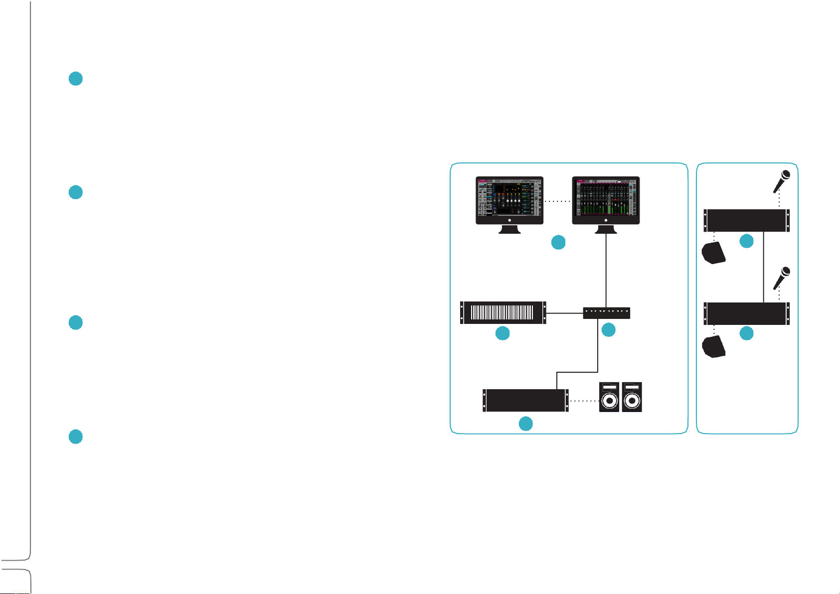
A SOUNDGRID NETWORK CONSISTS OF AT LEAST THESE FOUR HARDWARE ELEMENTS:
HOST COMPUTER: Controls the mixer as well as the SoundGrid
network that connects all devices. The eMotion LV1 application,
plugins, and preset files are located here. However, audio is not
processed here. The mixer application and the SoundGrid network
software run on both Mac and Windows and can support multiple
displays.
SOUNDGRID SERVER: The mixer’s “number cruncher.” All plugin
processing is offloaded from the host computer to the server.
The speed of the server has a direct impact on the number of
SoundGrid channels and plugin instances. There are a number of
server configuration options. Visit www.waves.com/hardware for
up-to-date specifications and requirements about severs and
other hardware components.
SOUNDGRID 1GB ETHERNET SWITCH: Links the I/O devices, server,
and host computer. There is a growing list of SoundGrid-approved
third-party Ethernet switches. Note the model and version of the
FOH Stage
switch you purchase: some versions work well, others don’t.
To ensure compatibility, we advise that you obtain Ethernet
switches through Waves.
AT LEAST ONE SOUNDGRID I/O DEVICE: All I/O devices are connected
via Ethernet, regardless of the number of channels. I/Os range from
2-channel preamps to 128-channel MADI interfaces.
Page 11
6
Waves eMotion LV1 User Guide | Introduction
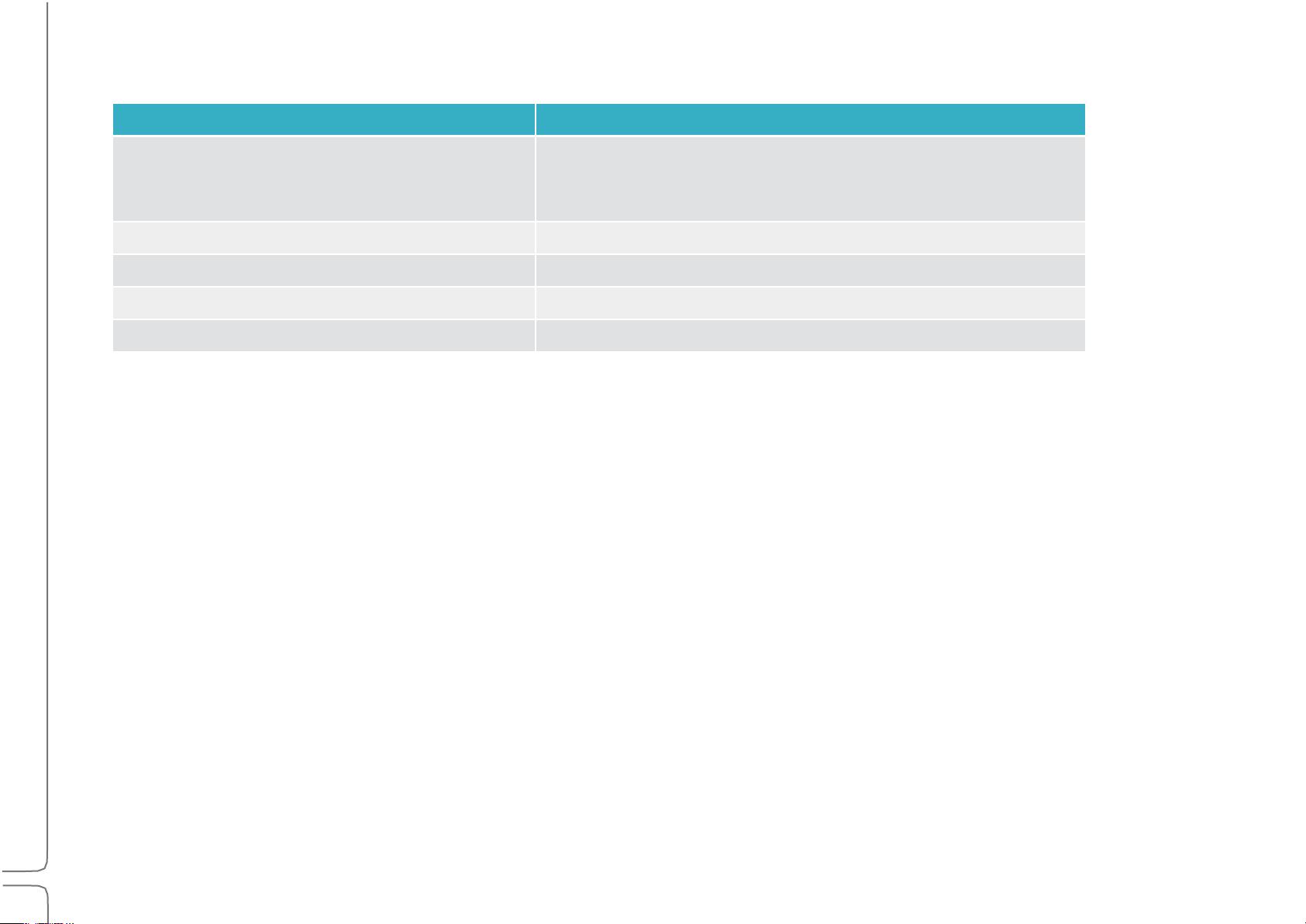
Host Computer Minimum Requirements
Mac OS
Windows
Model/CPU:+Mac Pro 4,1 or higher
MacBook Pro / iMac / Mac
Mini with Intel i5 CPU or higher
CPU: Intel i3 or higher
RAM: 6 GB
RAM: 8 GB
Operating+System: 10.10.5 to 10.13.x
Operating+System: Windows 8.1 / Windows 10 64-bit
Screen+Resolution:+1280x768 32-bit
Screen+Resolution:+1280x768 32-bit
Tablets:+Windows 8.1 / Windows 10 64-bit with Intel processor
Sample Rate Support
The eMotion LV1 mixer supports sample rates of 44.1 kHz to 96 kHz.
All Waves plugins support sample rates of up to 96 kHz; many support higher sample rates. Visit www.waves.com/support for details.
Page 12
7
Waves eMotion LV1 User Guide | Introduction
Connections
Node
Cable Length
Host computer to main switch
up to 100 meters
Server to main switch
up to 20 meters
Main switch to secondary switch
up to 100 meters
I/O device to main switch
up to 100 meters
I/O device to secondary switch
Up to 20 meters
LV1 can assign and patch to up to 16 I/O devices: any combination of hardware I/Os and drivers.
• A hardware I/O device can have up to 128 I/O channels, depending on the model.
• Computers using a SoundGrid ASIO/Core Audio driver can be configured for up to 128 driver channels.
Use a SoundGrid Ethernet switch and Cat 5e, Cat 6, or Cat 7 Ethernet cables to connect all hardware components. Note which of the host
computer’s Ethernet ports is being used for the SoundGrid network. This port can be used only for the SoundGrid network. Do not attach
an Internet or other network connection to the Ethernet switch. Use another port for these purposes.
MAXIMUM CABLE LENGTHS
Cat 5e/6/7 S/FTP
Cat 5 cables are not supported.
Joints, or cable extenders, can be used, but with care, since some models do not have electrically connected shielding. Using such
extenders in areas with interference may be problematic. Total cable length with the joint may not exceed the above maximum cable
length per node. Additional joints may reduce the effective cable runs.
Page 13

8
Waves eMotion LV1 User Guide | Introduction
SERVER REQUIREMENTS
All SoundGrid-approved servers will work with the eMotion LV1 mixer. Server performance has a direct impact on processing power and
on the number of mixer channels that can be played simultaneously. Check Waves.com or contact customer support to determine which
server best suits your needs.
DISPLAY RESOLUTION
The suggested display resolution is 1280x768. The mixer can accommodate one, two, or more computer displays. For details please
refer to Appendix B: Using Multiple Displays and consult the manufacturer of your video card and displays.
CONTROL
eMotion LV1 can be controlled in any of these methods:
• 5-point (or more) multi-touch interface
• Control surface supporting Mackie Control™ protocol
• MIDI controller
• Mouse/keyboard
Page 14

9
Waves eMotion LV1 User Guide | Introduction
Installing Software
Create a free Waves account if you don’t already have one (www.waves.com/create-account). This account is used to manage your
Waves products and licenses.
1. Register your Waves Products in your Waves account under ‘”Register New Products.” The product serial number (also called a
license number) can be found on your purchase invoice, in an email from your dealer, or in an envelope containing the registration
form. Once your registration is complete, a product license will be deposited in your license cloud.
2. Download Waves Central from the Waves website. Waves Central is an application for downloading, installing, and managing the
licenses of Waves software.
3. Download and install the eMotion LV1 mixer and any selected plugins. Next, move your licenses from your license cloud to the
computer you are using or to a USB flash drive.
4. If the host computer on which you’ll be running eMotion LV1 is not connected to the Internet, you can create an offline installer.
Learn more about Waves Central at www.waves.com/support.
5. Launch eMotion LV1.
WINDOWS USERS:
The Widows Power Plan must be set to High Performance.
Open the Control Panel\Hardware and Sound\Power Options window. Select the High Performance plan and re-launch
eMotion LV1.
Page 15
10
Waves eMotion LV1 User Guide | Introduction
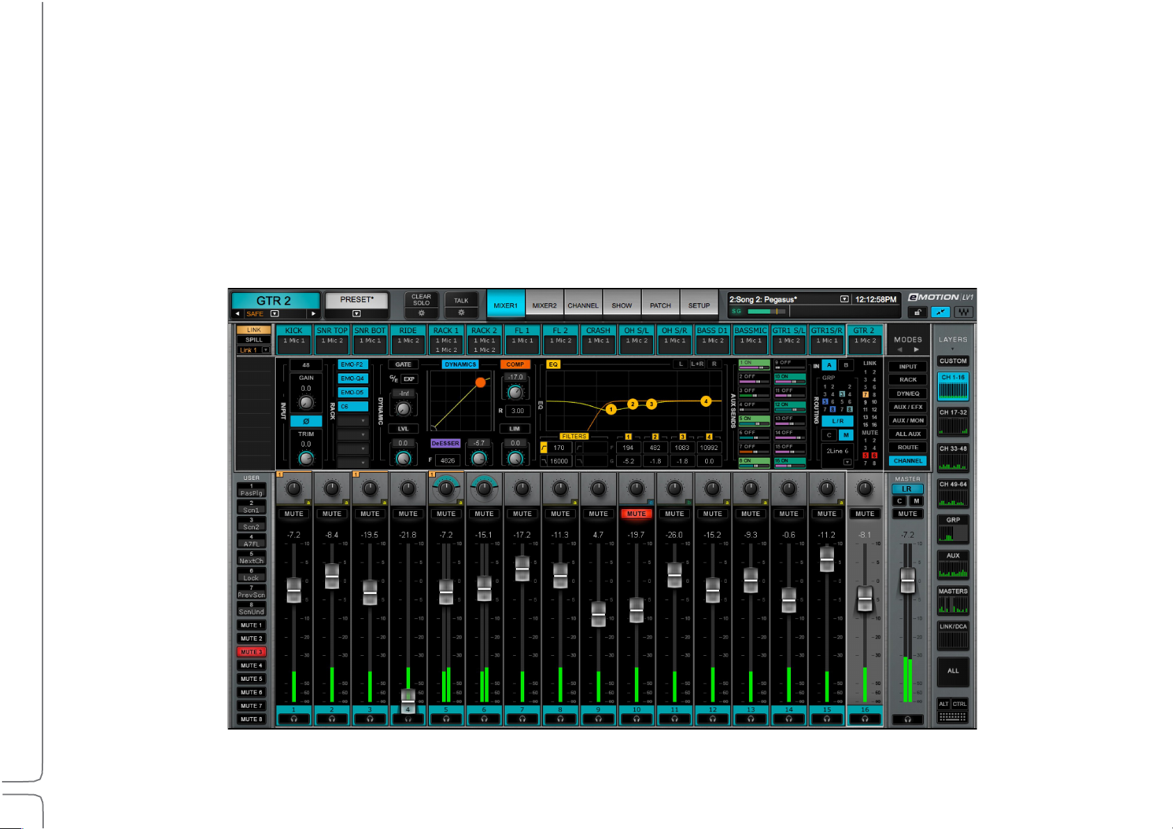
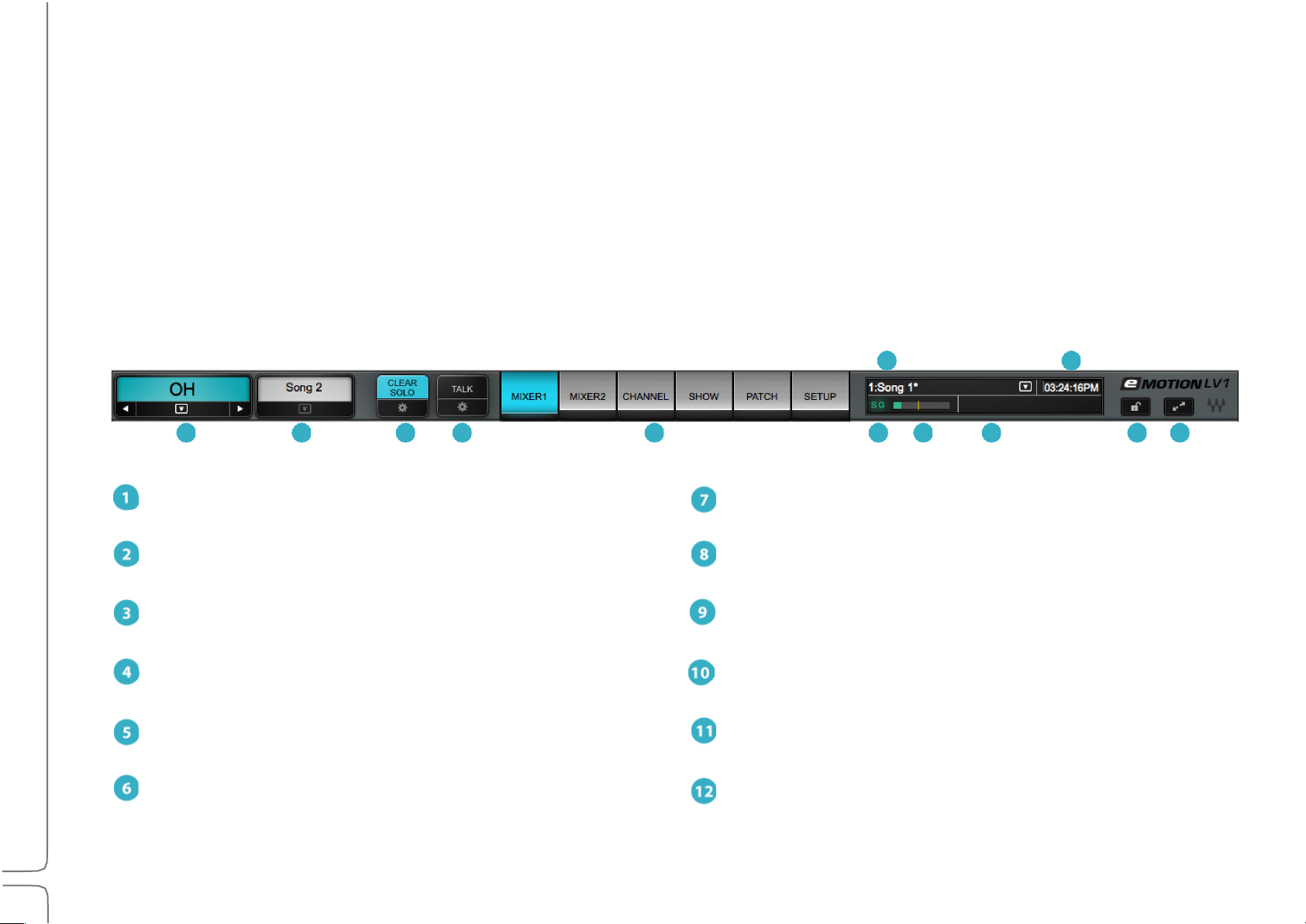
Top Bar
1
Name: Displays the selected channel
7
DSP meter: Displays average and peak processing loads
2
Presets Menu: Manages channel presets and sessions
8
Scenes: Stores and recalls scenes
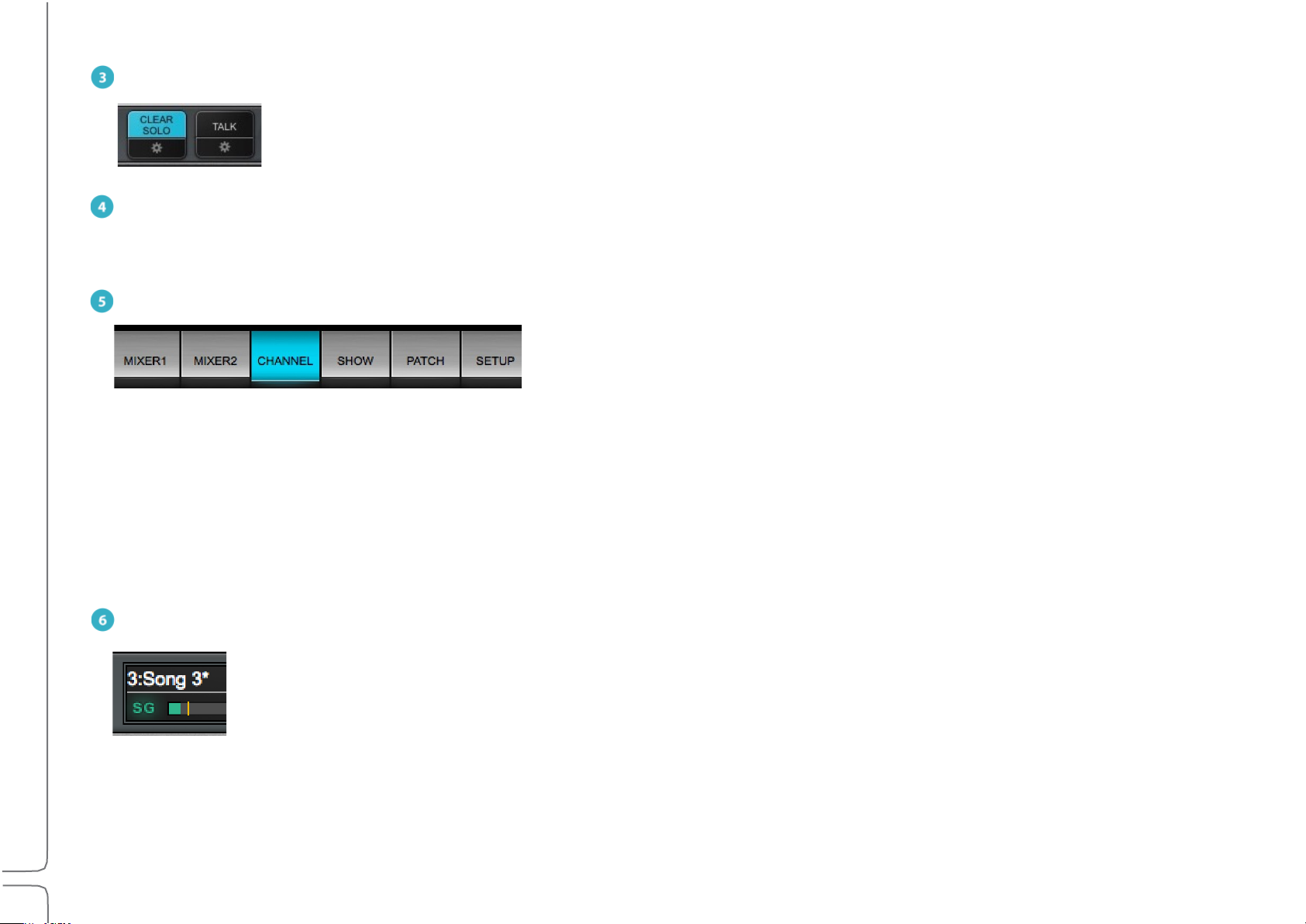
3
Clear Solo: Clears all solos or cues / accesses cue controls
9
Messages: Reports status and errors
4
Talk: Engages talkback / accesses the TB control page
10
Clock: Displays current MTC position
5
Window select tabs: Navigates to all mixer windows
11
Lock: Locks mixer surface, I/O routing, and/or plugins rack
SG (SoundGrid): Reports the status of the SoundGrid network
12
Full screen mode: Fits the mixer window to full-screen view
8
10
1 2 3 4 5 6 7 9 11 12
The Top Bar of the eMotion LV1 mixer is a navigation and management tool visible from all views. From here you can:
• Access all windows.
• Monitor network and processor status.
• Select a channel.
• Lock the mixer interface.
• Manage sessions and scenes.
• Engage talkback and clear all solos.
Page 16

11
Waves eMotion LV1 User Guide | Introduction
TOP BAR ELEMENTS
AME
N
This box displays the name of the selected channel. Side arrows move the channel selection higher or lower,
one channel at a time. The down arrow opens a drop-down menu used to access and select any channel directly. The
Name box background color is the same as the color of the selected channel.
PRESETS MENU
The Presets menu is divided into two sections that serve different purposes.
At the top is the Channel Presets menu section. Channel presets are snapshots of the current condition of the
selected channel. These menu items are used to save, load, export, import, and manage presets. Channel Recall Safe
status is also set here. Presets are saved as part of a session. To use presets from another session, choose the Import
from File menu item. The name of the current channel preset is shown in the Preset box above.
Beneath the Presets section is the Session menu section. It provides quick access to sessions and it enables the
presets for the entire current session to be saved to files.
The Presets menu is always visible from all windows.
Page 17

12
Waves eMotion LV1 User Guide | Introduction
Factory Presets (load)
A library of presets supplied by Waves. A factory preset cannot be modified. Instead, open it and save as a
user preset.
User Presets (load)
A list of user-defined channel presets, saved from within the current session or imported from another. To
delete a user preset, hold Ctrl before opening the Preset menu. When then opening the User Preset
menu, preset names will be preceded by “Delete.” Select the preset and it will be deleted. This cannot be
undone.
Import from File
Opens a navigation window to locate presets files that have been saved. Imported presets are added to
the User Presets menu.
Paste
Pastes the copied channel condition to another channel. The Copy command copies all rack information.
Paste enables you to choose what channel information will be replaced in the target track.
Save
Saves the channel condition to the loaded channel preset, overwriting it.
Save to User Presets
Creates a new user preset. These are saved as part of the current session. Consider this a “Save As”
function.
Rename Present
Changes the name of the current channel preset.
Save to File
Creates a file that is saved at a user-defined location and can be imported to any session (the extension is
xps). Unlike user presets, these are not embedded in the session.
Copy
Copies the current channel preset. A copied preset can be pasted to any other channel in the current
session. There are several Paste options.
Set Channel Recall Safe
Temporarily excludes all channel parameters from scene changes, even if those parameters are within
the scope of the scene change. A Small “Safe” indicator appears next to the channel name when it is in
Recall Safe mode.
Update Current Scene
Updates the loaded scene with the current mixer condition.
Page 18

13
Waves eMotion LV1 User Guide | Introduction
Session Menu Section
Export User Presets
Creates a file with all user presets for the entire session, not just those of the selected channel. The
exported presets are stored as one .xps file that can be saved to other media.
Export All Presets
Exports a file that contains the presets—not just the user presets—of all channels in the session.
Load Session
Presents a list of existing sessions. If the current session is not saved, you will be prompted to do so.
Load Session Template
Presents a navigation window for loading a session template. Loading a template does not alter the
current I/O inventory and external patching.
Save Session
Overwrites the loaded session file with the current mixer condition.
Save Session As
Saves the current mixer condition as a new session.
Save Session Template
Saves the current session as a session template.
This menu section is used to manage presets for the entire current session. It is also used to save and load mixer sessions.
Sessions and Templates are discussed in the Show chapter of this User Guide.
Page 19
14
Waves eMotion LV1 User Guide | Introduction
CLEAR SOLO
Mixer 1 and 2
Two multi-mode, multi-layer mixing interfaces.
Channel
A detailed view of a selected channel. A channel’s inputs and outputs, aux sends, and plugin processing can be
controlled here.
Show
A workspace for managing sessions and scenes.
Patch
A patch bay for connections between the mixer and I/Os, within the mixer, and between devices.
Setup
Assigns I/O devices, servers, and controllers. Manages mixer, network, and interface settings.
Clears active solos or cues on all tracks.
Cues and solos are activated on the Mixer window. Configure Cue in the Cue control page, which is accessed with the
Gear button below Clear Solo. Refer to Channel > Cue Section for more about the cue function.
TALK
Activates talkback. Click on the gear button to access the Talkback configuration page. Refer to Channel >Talkback Section for more
about the Talkback function.
WINDOW SELECTION TABS
Radio button tabs that navigate to the six mixer windows.
SG (SOUNDGRID)
Reports the status of the SoundGrid network. A green SG indicates a normal condition. Red indicates an error, such
as a lost connection to the network or a server error. When the SoundGrid network is down, the mixer can still be
used in an offline mode with offline devices assigned in its inventory. Go to Setup > System Inventory to investigate
network problems.
Page 20
15
Waves eMotion LV1 User Guide | Introduction
DSP
One indicator displays average and peak processing loads. The average value is displayed as a green bar and peak as
an orange line. Red indicates that an audio drop has occurred. This may happen for two reasons:
Processing overload (momentary or constant) Solution: Disable some plugins
Some plugins exhibit a high average/peak ratio. This may cause temporary CPU overloads that result in audio drops. When adding a
large number of these plugins, the peak and average indicators will drift apart. In such cases, some of these plugins may need to be
disabled.
High network usage (channels over the network) Solution: Increase server network buffer size.
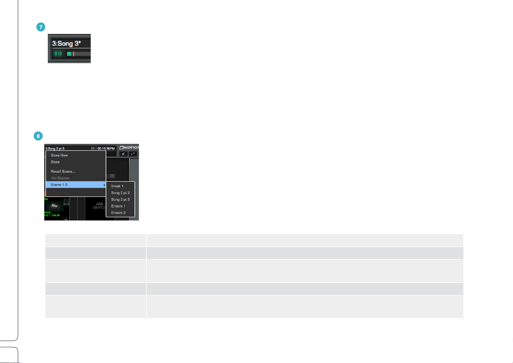
SCENES MENU
The Scenes menu is used to quickly store and recall scenes within the current session. The name of
the current scene is displayed in the box. If a scene has been modified since it was recalled, it is
followed by an asterisk (*). The Scenes menu is available from any window.
Store New Creates a new user-named scene based on current condition.
Store Overwrites the recalled scene with current mixer condition.
Recall Scene
Hot Scenes Provides immediate access to up to eight high-priority “Hot” scene snapshots.
Scene 1–32
(scene select submenu)
Directly recalls a scene based on its place in the scenes list. Type a number and the
corresponding scene will be recalled.
Shows all scenes associated with the session in banks of 32 scenes.
Maximum number of scenes: 1000.
Page 21

16
Waves eMotion LV1 User Guide | Introduction
MESSAGES
Reports network status. Messages may indicate a sample rate mismatch, a general change in network status, buffer overload, etc.
Troubleshoot network and device issues in the System Inventory page (Setup > System Inventory).
CLOCK
When MIDI control is used, this box can display MIDI time code.
LOCK
Locks/unlocks mixer surface, I/O routing, and/or plugin parameters to prevent unwanted changes during a live event. The scope of
mixer lock is defined in the Setup window (Setup > Mixer Settings > Lock). A password can be assigned to this function.
FULL SCREEN MODE
Fits the mixer window to full-screen view. Click again to return to normal view. Use the recommended resolution of 1280 x 768 for
ideal full-screen display.
Page 22

17
Waves eMotion LV1 User Guide | Introduction
CHAPTER 1
T
SETUP WINDOW
he Setup window provides the tools to configure the
mixer and determine its behavior.
The window has three pages:
• System Inventory
• Mixer Settings
• U/I Settings
Use the tabs on the left side of the window to choose
between these pages
Page 23
18
Waves eMotion LV1 User Guide | Chapter 1: Setup Window
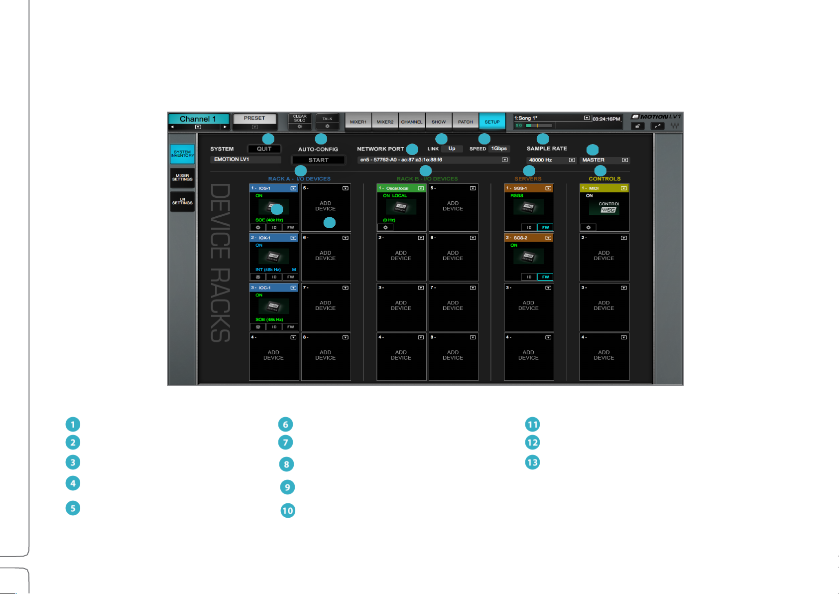
1
Quit application
6
System sample rate
11
Control racks
2
Auto-configure devices
7
Sample rate master/slave selector
Populated rack slot
3
SoundGrid network port selector
8
I/O Racks A (hardware + software I/Os)
Empty rack slot
4
Ethernet link status indicator
I/O Racks B (hardware + software I/Os)
5
Network speed indicator
10
Server Racks
13
12
11
10 9 8
3
6 5 4 2 1
System Inventory Page
The System Inventory page is used to assign and manage I/Os, servers, drivers, and controllers. The top portion of the page deals with
network status. Devices are assigned in the racks below.
Page 24

19
Waves eMotion LV1 User Guide | Chapter 1: Setup Window
System Inventory Page Displays and Controls
This section describes the controls and menu items of the System Inventory page. It is followed by examples of how to use the System Inventory
page in order to set up the mixer (Setup > Configuring a Basic Mixer Setup).
1. Quit
Closes the session and quits the application. When the mixer is in full-screen mode, use this button to exit the application. When it is not
in full-screen mode, closing the application windows will quit the mixer.
Before quitting, the mixer prompts whether or not to save the current session.
Yes: Save the current mixer condition on the existing file. No: Quit without saving.
NETWORK CONTROLS
2. Auto-Configure / Start
A mixer system can be configured manually or with the aid of an auto-configure tool. This tool inventories all devices in the SoundGrid
network and then sets up a mixer system based on available assets. The resulting session includes device assignment and patching, as
well as mixer configuration. Auto-configure is discussed later in this chapter (Setup > Using the System Inventory Page > Configuring a
Basic Mixer Setup).
3. Network Port
Shows all detected network ports on the host computer. Choose the port that connects to the SoundGrid devices or network switch. We
recommend that this port is used exclusively for SoundGrid devices.
4. Link
Reports the status of the Ethernet connection to the computer running the eMotion LV1 software. Options: UP / DOWN / INVALID
5. Speed
Reports the speed of the SoundGrid network. Options: 100 Mb/sec, 1 Gb/sec, N/A.
Page 25

20
Waves eMotion LV1 User Guide | Chapter 1: Setup Window
Sample Rate Controls
6. Sample Rate Master/Slave Status Selector
Controls whether the mixer is the sample rate master or a slave. As such, it determines how the sample rate of a system is established.
7. Sample Rate Selector Menu
Sets the system sample rate when the mixer is the sample rate master. The Sample Rate window displays the sample rate of the system.
The menu is disabled when the mixer is a sample rate slave, since it can set the sample rate only when in the master mode.
The sample rate of the clock master device can always be set from its control panel, whether the mixer is in Sample Rate Master or Slave
mode. Sample rate is discussed later in this chapter (Setup > System Inventory > Sample Rate Master vs. Sample Rate Slave).
DEVICE RACKS
8. I/O Rack A
Assign up to eight I/O devices. These can be hardware devices, software I/Os (drivers), or a combination of these.
9. I/O Rack B
Assign up to eight I/O devices. Racks A and B are identical.
10. Servers Rack
Assign up to eight I/O devices per rack. These can be hardware devices, software I/Os (drivers), or a combination of these.
The two racks are identical.
11. Control Protocols Rack
Assign control surface devices.
12. Populated Device Slot
When a device has been assigned to a slot, its icon appears here. The icon contains information about the device.
13. Empty Device Slot
A slot with no assignment is labeled “Add Device.”
Page 26
21
Waves eMotion LV1 User Guide | Chapter 1: Setup Window
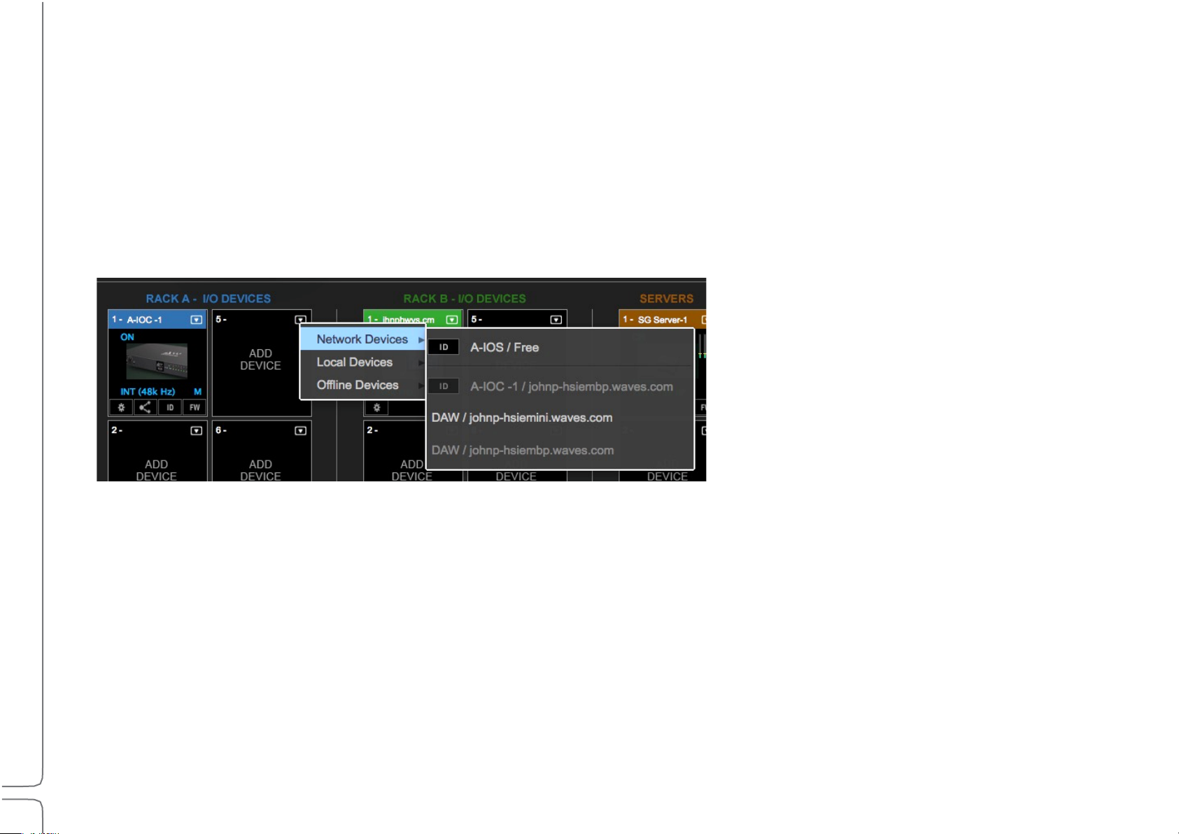
Device Racks: Configuring and Managing Network Devices
Network+
All working devices attached to this SoundGrid SOE network
Local+
The host computer’s drivers
More than one driver can be assigned to an eMotion LV1 system. This provides for a primary driver as well as backups
Offline+
Templates of devices that can be used to create sessions without a server and I/O devices
Device Racks are used to assign and control the hardware and software I/Os, servers, and controllers available on the network. Use these
to set up a new configuration or to modify an auto-configured setup.
Racks A and B—I/O Devices
Racks A and B assign hardware and software I/O devices to the mixer. Racks A and B can be used interchangeably.
A rack consists of eight slots, each of which can hold one I/O device. The arrow in the rack slot opens a drop-down list of devices that are
part of the mixer’s SoundGrid network.
There
are three categories of assignable devices to choose from.
Available devices are shown in black. Devices that are not available for assignment are gray.
The rack slot number determines the device’s place in the Patch window and in certain drop-down menus. Device sequence is not
important, but some engineers choose to use one rack for PA devices and the other for monitoring.
The ID button next to the device name activates a changing-color LED on the device front panel to help identify the physical unit.
Page 27
22
Waves eMotion LV1 User Guide | Chapter 1: Setup Window
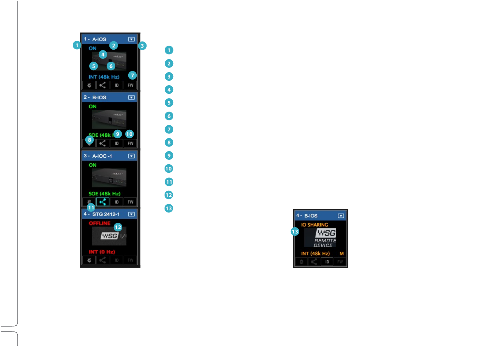
I/O Device Racks Displays and Controls
1
Slot sequence number
2
Device name
3
Device menu access
4
Device status
5
Clock source
6
Sample rate
7
Clock master indicator
8
Device’s control panel button
Identify hardware
Firmware status and re-flash
Enable sharing
11
Offline device
Shared device
There are several status indicators and buttons on the icon itself and just below it. The color of the text in the slot indicates the master/
slave status of the device.
(Blue=Master; Green=Slave; Red=Device not available)
Page 28

23
Waves eMotion LV1 User Guide | Chapter 1: Setup Window
Indicator
Possibilities
Function
Slot Sequence
Number
Rack A 1–8; Rack B 9–16
Indicates the rack slot number. I/Os appear in the Patch window in this sequence.
Device Name
Text entry
The device product name followed by a number is the default name. Change
the device name by double-clicking on its Name Box.
Devices Menu
Drop-down menu
Used to add and remove devices from the slot and to set the device as clock
master.
Device Status
On
Device is active.
NA
Device is unavailable. Likely causes:
•Device is assigned to another system.
•Device or firmware is incompatible with current SoundGrid Studio software.
•Device was previously assigned to this user, but is not currently connected.
Offline
A virtual device is assigned to this rack slot for offline preparation of sessions
without I/Os connected. All device patching will be maintained when the session
is launched on a complete system.
Clock Source
INT, SOE, AES, WC, DigiLink
Clock source of this device.
Sample Rate
44.1, 48, 88.2, 96 kHz
Sample rate of device.
Clock master
M (Master) / (blank = slave)
Identifies the device as the clock master of the SOE network.
Control Panel Access
Gear button
Click to access device’s control panel to adjust preamps, configure channels,
and control clock. Refer to the I/O device manufacturer’s user guide for more
information.
ID Hardware
Locate hardware device
Activates lights on the front panel of the hardware device associated with the
icon.
Page 29
24
Waves eMotion LV1 User Guide | Chapter 1: Setup Window
FW
Status of device’s firmware:
Gray
Firmware is compatible with installed mixer software.
Blue
Firmware is compatible with installed mixer software, but a newer version
exists. Firmware should be updated as soon as possible.
Red
Firmware is not compatible or is out of date. Click the FW button to re-flash
device hardware.
Offline device
Red
Device is offline.
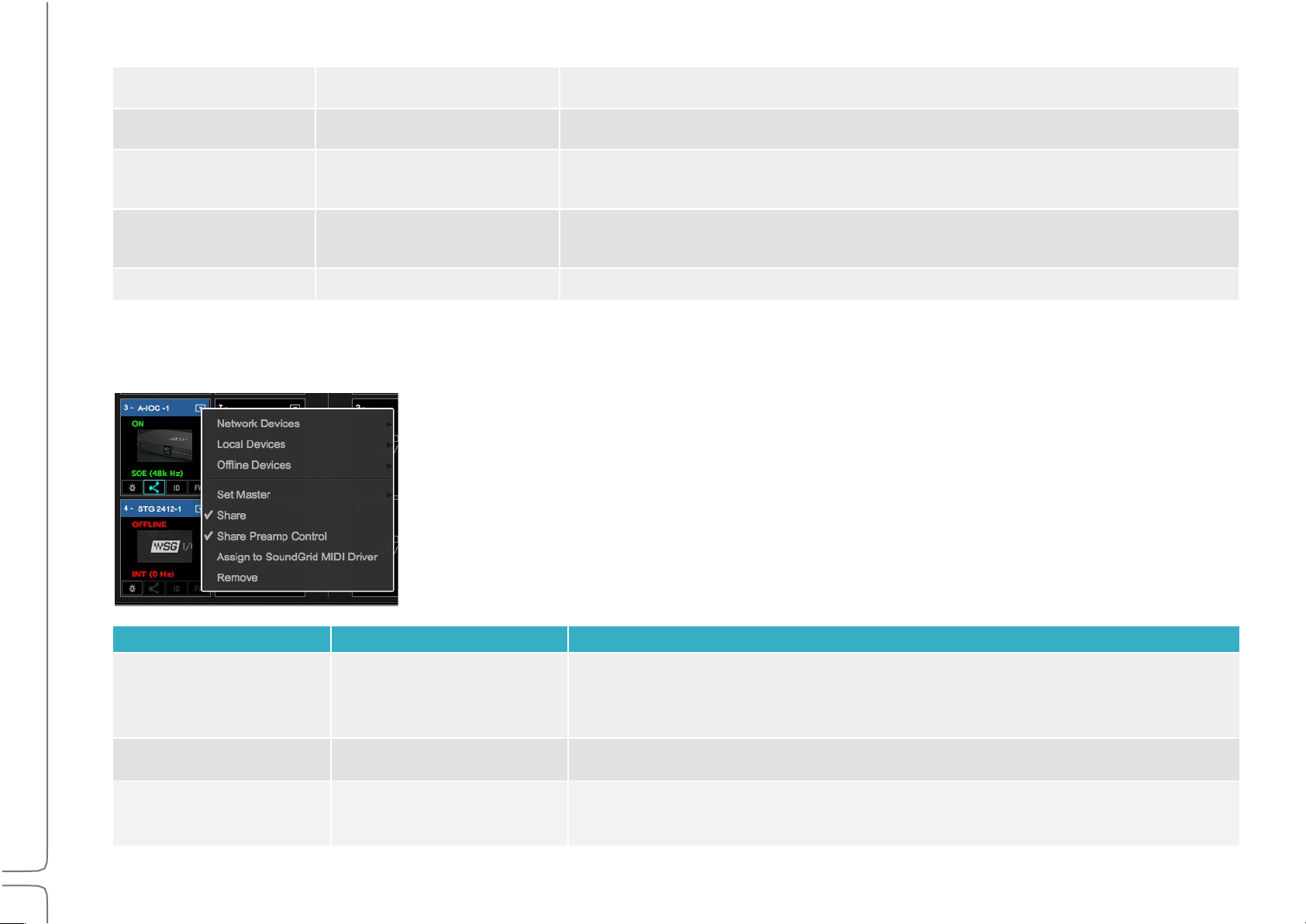
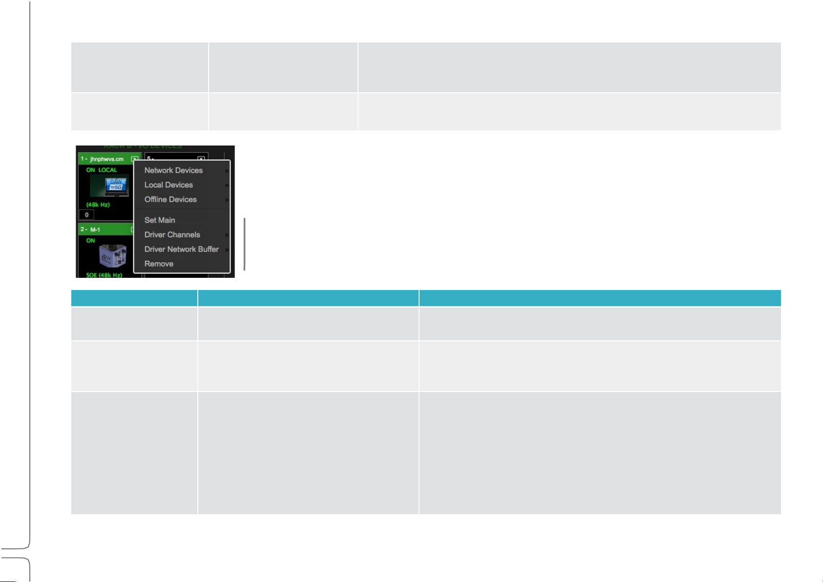
I/O Devices Menu Items
Menu Item
Possibilities
Function
Set Master
A list of all devices that can
be used as a clock source
for the local SOE network.
Designates the device as the SOE network clock master and other devices clock
slaves. The letter “M” and the blue text in the slot indicate that the device is the
master.
Share
Check/Uncheck
Allows sharing of I/O channels on this device with other systems.
Share Preamp Control
Check/Uncheck
Allows remote users to control the preamps of the shared device.
Once an I/O device has been assigned to a rack slot, additional menu items are available.
Page 30
25
Waves eMotion LV1 User Guide | Chapter 1: Setup Window
Assign to SoundGrid
MIDI Driver
Check/Uncheck
Assigns any MIDI-port-equipped I/O device to the SoundGrid MIDI driver. The
device can then serve as a port for other MIDI devices. The assigned device
appears to MIDI controllers as “SG Device I/O.” Refer to Appendix 2.
Remove
Releases the device from the local host. It will then be available to other
drivers.
These menu items apply only to drivers.
Menu Item
Possibilities
Function
Set Main Driver
Assigns main driver.
Assigns this as the main driver. The second driver serves as a
backup.
Driver Channels
Range: 32–128 channels
Default: 32 channels
Sets the number of channels assigned to the SoundGrid ASIO/Core
Audio driver. More driver channels can increase network load and
may require more buffering.
Driver Network Buffer
(Values in samples)
Range @ 44.1–48 kHz:
104, 144, 192, 240, 288, 336, 384, 432,
480, 528, 576, 1024
Range @ 88.2–96 kHz:
208, 256, 304, 352, 400, 448, 496, 544,
592, 640, 1088.
The network buffer helps the OS send synchronized information
between the ASIO/Core Audio drivers and the I/Os through
the network port. When many channels are going in/out of the
driver(s) to several destinations, the Driver Network Buffer may
need to be increased to reduce the possibility of audio drops or
artifacts as a result of overloading the network port driver.
All computers on the network should have the same up-to-date versions of eMotion LV1 and SoundGrid Studio software installed. You
can download the latest version from Waves.com.
Page 31
26
Waves eMotion LV1 User Guide | Chapter 1: Setup Window
I/O Sharing
An eMotion LV1 system consists of a host computer, an Ethernet switch, at least one SoundGrid server, and a least one I/O. These
elements communicate through a SoundGrid SOE network. All connected I/O devices within this system can be assigned and patched to
the eMotion LV1 host.
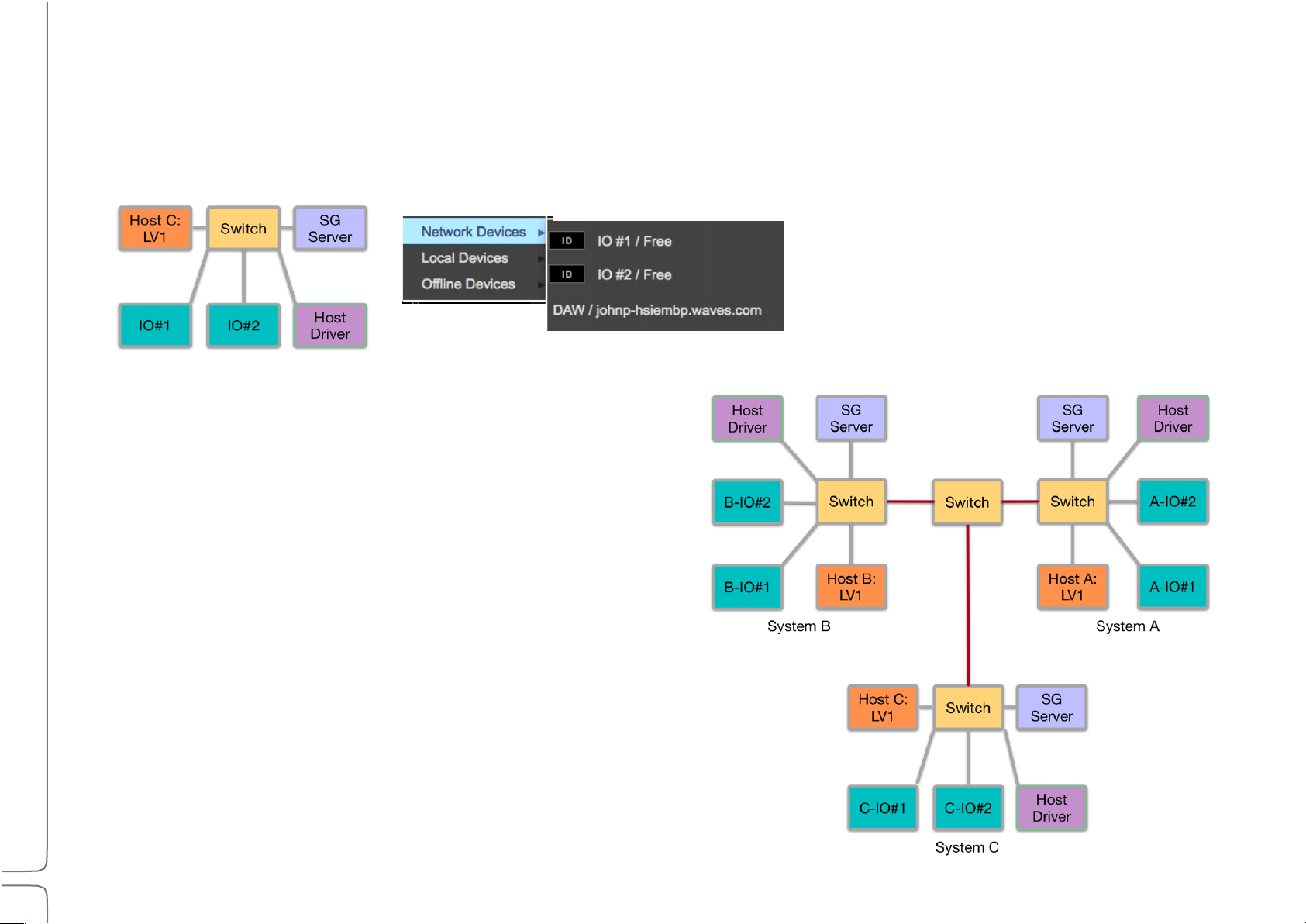
Single freestanding eMotion LV1 system:
All I/O devices, servers, and local drivers in this SOE
network are seen in the System Inventory.
CONNECTED SYSTEMS
Multiple eMotion LV1 systems can be linked by connecting their
Ethernet switches. This enables hosts within this “super system”
to build private networks from all connected I/Os, servers, and
drivers. These assignments are exclusive—devices assigned to a
host are available only to that host until they are un-assigned.
Other users will see the devices in their System Inventories, but
they will be grayed out and unavailable.
An eMotion LV1 system does not need the permission of other
systems to assign an available device to its Inventory.
Page 32

27
Waves eMotion LV1 User Guide | Chapter 1: Setup Window
SYSTEM INVENTORY IN SUPER SYSTEMS
All devices in a super system—whether assigned to a host or not—are displayed in the Device menu of each
independent system’s Inventory (left). There are five I/O devices, none of which have been assigned to a
system. Each connected host’s local driver is also shown.
A device assigned to a host’s inventory is the manager of the device. When a device is removed from a host, it
becomes Free and it can be assigned by any other host, which in turn becomes its manager.
Sharing a Device
Device sharing enables hosts to assign devices that are already claimed by other hosts and patch available device I/O channels. A host
that patches I/O channels from a device that’s been assigned to another host (the manager) is called the client of that device. A host can
be a manager of some devices and a client of others. A device can have several clients, within the limits of the device’s maximum output
to the network. Each destination establishes a direct connection from the shared IO device, so the total outputs to the network increase.
For example, a 128-input MGB patched to four hosts will use up the 1 Gb network capacity of the SoundGrid network. In this case, the
device will output 128 x 4 channels=512 channels (at 48 kHz).
Note: Servers and drivers cannot be shared.
Page 33
28
Waves eMotion LV1 User Guide | Chapter 1: Setup Window
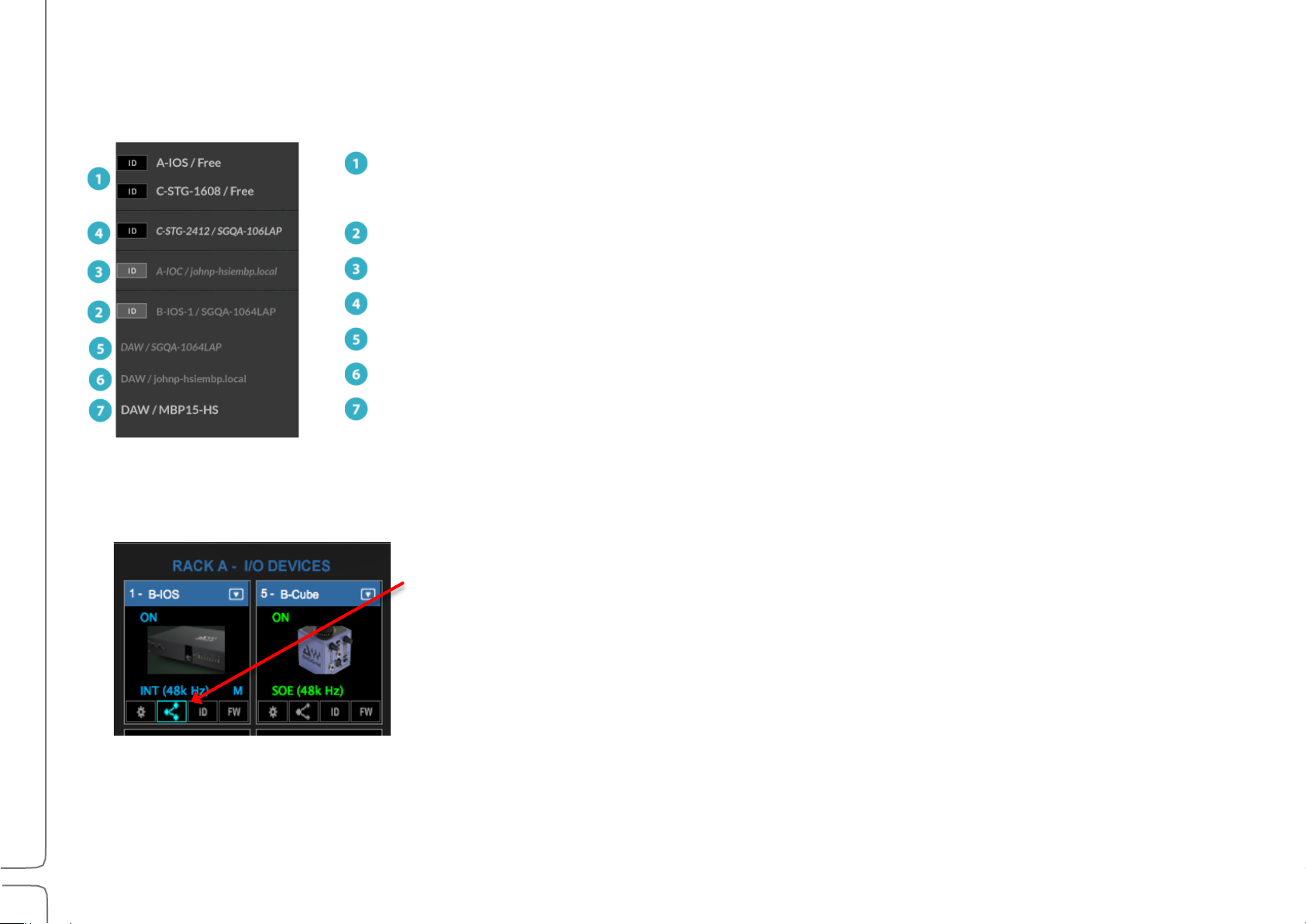
Unassigned devices
Once a device is assigned, its name is followed by the name of the host to which it is assigned.
Device assigned to local host (grayed out, roman type)
Device assigned to another system (grayed out, italics)
Sharing-enabled device on another system (not grayed out, italics)
Driver assigned to another system
Driver assigned to local host
Unassigned driver
This Device menu illustrates numerous device assignments, unshared and shared. Font style and shading indicate the type of
assignment.
SETTING UP DEVICE SHARING
Select the assigned device you wish to share. Click the device’s Sharing icon. The device is now sharable.
Sharing can also be enabled from the Device menu. Only the manager of a device can activate its sharing.
Other systems can now assign the I/O device to their Inventories and patch available I/O channels.
Output I/O channels patched by the manager cannot be shared with other systems until the device’s
manager releases the patches or removes the device from its inventory.
Page 34

29
Waves eMotion LV1 User Guide | Chapter 1: Setup Window
CLOCKING CONSIDERATIONS
When a device is shared by two systems. both systems must be locked to the same clock master. If a client system assigns a shared
device that’s part of a system with a different clock source, something must be done to rectify the difference.
When assigning a shared device whose clock source is not the same as that of the client system,
this prompt will appear. Click OK to set the clock of the client system as your system’s clock. The
shared device, or its master clock, is now the local SOE clock master for all the devices in your local
SoundGrid network.
Cancel to explore other ways to provide a clock common to both systems.
In this example, device A-IOS is shared with eMotion LV1 system B. This means that the device is now
assigned to two independent systems (A and B) that must be synchronized to the same master clock
device. In this example, A-IOS becomes the clock master of system B—all other devices become SOE slaves.
It is possible to assign another device as the clock master while using a shared device, as long as all devices
share the same clock.
Use each system’s Set Master menu to re-assign clock masters. Select the same device in both
systems, if possible, and the clock will be common to both systems.
The shared device can now be a slave in the client system.
Page 35

30
Waves eMotion LV1 User Guide | Chapter 1: Setup Window
If the shared device cannot synchronize to the new clock, it will be unavailable for sharing by that host. Other eMotion
LV1 hosts in the super system may be able to sync to the shared device if they can adjust their clocks accordingly.
A shared device can be a slave or the clock master of in its own SOE network, indicated by
the M on the shared device’s icon (left). On the right, the device is still the SOE master of
the system it’s being shared with but is a slave within its own system.
When devices from more than two systems are assigned to a system’s inventory, all systems must be locked to the same
master clock device.
Note: Changing the master clock assignment in a system that includes shared devices will result in a clock reset in all associated
systems. This results in a short audio dropout.
Page 36

31
Waves eMotion LV1 User Guide | Chapter 1: Setup Window
Patching Shared Devices
Patching Shared Input Devices
When a device is shared, all of its inputs are available to all users. The shared device
appears in the Patch window with the non-shared devices.
PATCHING SHARED OUTPUT DEVICES
Once assigned, a shared I/O device appears in the client’s Output Patch window. “IO Sharing, Remote Device” is shown on its
icon. Patching shared I/Os follows the same conventions as patching unshared SOE devices. There are, however, a few
considerations when sharing devices. In the example on the next page, the device “B-IOS” is owned by LV1-FOH and is being
shared by LV1-STG.
Page 37

32
Waves eMotion LV1 User Guide | Chapter 1: Setup Window
SHARED AND UN-SHARED DEVICES IN THE PATCH
B-IOS, owned by LV1 #1 LV1 #2, using shared device B-IOS
Device B-IOS appears as an assigned device in the
output patch of LV1 #1 (left) and as a shared remote
device in LV1 #2 (right).
When an output patch is made in either the system, the corresponding I/O channel in the other system is colored orange to
indicate that the patch is in use.
A manager can always disconnect an I/O channel and establish its own connection.
LV1 #1 (left): Analog line outs 6 and 8 are orange,
indicating that those channels have been claimed by
another system, in this case, LV1 #2. Local patches are
shown in green.
LV1 #2 (right): Analog line outs 1, 2, 4, and 5;
headphones 2L and 2R; AES 1 and 2 are patched by
LV1#1, the device manager, so they are unavailable for
patching by other systems
Page 38

33
Waves eMotion LV1 User Guide | Chapter 1: Setup Window
If the manager of a device patches to an I/O channel that’s already taken by a client, the
preexisting client patch will turn red. The client is no longer patched to that I/O output
channel.
Patching shared outputs in the Mixer and Channel windows follows the same rules as in
the Patch window. Devices shared by other system in the super system are indicted with
<shared>.
A warning alerts the client that the original patch has been disabled. When the manager
releases the patch, it will return to the client.
Page 39

34
Waves eMotion LV1 User Guide | Chapter 1: Setup Window
REMOVING SHARED DEVICES
Client
Manager
Select Remove from the Devices drop-down menu. Since the remote device
is, by necessity, the local clock master, removing it will result in another
device becoming the clock master. This prompt will appear. Once the device
is removed, SOE clock will return to the previous master.
This may result in a short audio drop.
Deselect the Sharing icon, or uncheck Share in the Device menu, to end
sharing for a device. If you attempt to remove a device that is being used by
another system, this prompt will appear. You will not be able to un-share the
device until it is not patched by other clients.
Page 40

35
Waves eMotion LV1 User Guide | Chapter 1: Setup Window
IF THE SHARING HOST BECOMES UNAVAILABLE
If the manager of a shared device fails (e.g., Ethernet connection is broken, computer stops
working, computer is taken away), the shared device will continue to function. As long as the
device is powered up and is connected to the manager’s SoundGrid network, it will pass audio.
The device, however, is still owned by the missing host, so a client cannot access the device’s
control panel.
To gain full control of the shared device, select “Manage Device” from the device’s menu. This, in
essence, moves the device’s administrative privileges from the missing manager host to the
client’s computer.
The device will now appear in the client’s inventory as a local SOE device. It can be designated as
a clock master or slave of the SOE network.
If the absent manager system is sharing devices with yet other systems, this operation may
interfere with some connections.
HARE PREAMP CONTROL
S
A device manager can enable all clients in a super system to adjust the preamp gain for a
shared device. When Share Preamp Control is selected, any client host can adjust the
preamp gain of any I/O channel of the device. All users sharing this device have equal control
of preamp gain in any patched I/O channel.
For more information on how to control gain in multi-client environments and how to retain
your gain structure while other users are controlling preamp gain, refer to Channel > >Input
Sections >Controlling Preamp Gain on Shared Devices.
Page 41

36
Waves eMotion LV1 User Guide | Chapter 1: Setup Window
Servers
Menu Item/Indicator
Possibilities
Function
Devices
Drop-down menu
Choose among the servers on the SoundGrid network. A server that is
assigned to another host is unavailable and grayed out.
Server Network
Buffer
Range+@+44.1–48+kHz:+
40-96 samples
Default: 40 samples (0.8 ms)
Range+@+88.2–96+kHz:
80-192 samples.
Default: 80 samples (0.8 ms)
This sets the amount of time it takes for audio to stream from the I/O to the
server and back, determining the speed of real-time processing. Lower settings
result in lower system latency and greater responsiveness. Higher settings yield
more stability but greater latency. If you encounter pops or similar
errors, increase the buffer setting. The buffer size is set in samples but is also
displayed in milliseconds.
Information
(N/A)
Displays technical details about the server.
Remove
Releases the server from the local host. It will then be available to other hosts.
Server Status
Indicator
On
(N/A)
Indicates that the server is present and operational. The server’s rack slot will
remain red until the firmware is compatible with current SoundGrid software.
Launch the updater manually by clicking the FW (firmware) button.
The Servers rack is used to assign, remove, and configure a SoundGrid server.
The server’s CPU temperature is shown on the icon.
Using a Second Server
Assign a second server to provide redundancy in the event that the primary server fails. Switchover to the second server is
automatic. It takes a few seconds. During this period sound is muted.
Page 42

37
Waves eMotion LV1 User Guide | Chapter 1: Setup Window
DSP Meters
Average
Peak
Status
Green
DSP peak value: 1% to 84%
System is stable. You can add more plugins.
Yellow
DSP peak value: 1% to 84%
The network is approaching its limit. Monitor the
meter status and be prepared to remove some
plugins and/or increase the network buffer size.
Yellow
DSP peak value: 85% to 99%
Network load is excessive. Monitor the meter
status. Remove some plugins and/or increase the
network buffer size.
Red
DSP load is beyond the limit. Remove heavy-load
plugins immediately.
The meter bars on a server icon indicate DSP usage of each of the server’s cores. There is one meter per core.
The solid bar areas display average DSP use per core:
The yellow lines show peak use, as indicated in the percentage display above the line. Certain plugins can exhibit a high
average/peak DSP ratio. This may cause overloads (momentary or constant) that result in audio drops. When adding a large number
of these CPU-hungry plugins, the peak and average indicators will drift apart. In such cases, you may need to disable or remove
certain plugins.
Page 43

38
Waves eMotion LV1 User Guide | Chapter 1: Setup Window
Indicator/Menu Item
Possibilities
Function
Selected Control Category
Displays selected protocol.
Controller Device Status
Displays presence and status of device
N/A > Device corresponding to the selected protocol is
not present or not functioning properly.
On > Device is present and operational.
Assess Control Panel
(Gear Button)
Momentary switch
Opens the control panel of the selected controller.
Devices menu
Drop-down menu listing available control
protocols
All available controller categories are listed, whether the
associated device is connected or not.
Remove
Unassigns the control protocol.
External Control Devices
Use this rack to assign external controllers to the mixer.
Control Panel
Each controller category has its own control panel: they all behave in a very similar manner. Please refer to Appendix 1 for details about
controlling the mixer with an external device.
A mixer or plugin parameter currently being controlled by an external device is highlighted by a red bracket.
Page 44

39
Waves eMotion LV1 User Guide | Chapter 1: Setup Window
SAMPLE RATE MASTER VS. SAMPLE RATE SLAVE
The clock master device sets the sample rate for all devices in the system—everything locked to its clock will adjust to its sample rate.
Although the clock master distributes clock at a specified sample rate throughout the system, it does not necessarily determine what that
sample rate will be. This is fixed by the sample rate master, which can be the clock master, or the mixer, or another system that provides
clock. Almost any device whose sample rate can be set can be a sample rate master.
There are two drop-down menus that control how sample rate is set.
1. Sample Rate Master/Slave Status Selector
This menu controls whether the mixer is the sample rate master or a slave. As such, it determines how the
sample rate of a system is established.
Mixer+as+Sample+Rate+Master+
When set to Master mode, the Sample Rate menu setting instructs the clock master device to change its sample rate. This in turn
changes the sample rate of all SoundGrid devices in the mixer system. The clock master supplies the requested sample rate from any of
its available sources (e.g., AES, S/PDIF, Word Clock, Internal. The priority of clock sources differs according to the specific device). If none
of these sources can switch to the desired sample rate, the clock master’s icon will turn red, as will the sample rate indicator. Audio will
mute. At this point, you can choose to stay at the previous sample rate or find another means of clocking the system.
Mixer+as+Sample+Rate+Slave+
When set to Slave mode, the mixer system sample rate is determined by another system. When the sample rate of the clock master
device changes, the mixer automatically adjusts its sample rate to match.
The mixer system can, for example, receive clock from another system, such as a hardware mixing console. If the hardware mixing
console is the clock and sample rate master of its system and the SoundGrid system is locked to that, then eMotion LV1 must assume
the role of sample rate slave.
2. Sample Rate Selector Menu
Sets the system sample rate when the mixer is the sample rate master. The Sample Rate window displays
the system’s sample rate.
The menu is disabled when the mixer is a sample rate slave, since eMotion LV1 can set sample rate only when in the master mode. The
sample rate of the clock master device can always be set from its control panel, whether the mixer is in Sample Rate Master or in Slave
mode.
Page 45

40
Waves eMotion LV1 User Guide | Chapter 1: Setup Window
Using the System Inventory Page
This section demonstrates how to set up a basic mixer system and how to work offline without a server or I/Os.
Configuring a Basic Mixer Setup
Below is an example of an eMotion LV1 mixer setup. This configuration provides two I/Os for stage and one I/O for FOH and PA. There is
no real difference between configuring a small system or larger one. It’s just a matter of scale. Refer to the eMotion LV1 Quick Start Guide
for an overview of system setup.
1. Configure Hardware
Use Cat 5e, Cat 6, or Cat 7 cables to connect all devices to the network switch.
FOH Stage
Host computer + eMotion LV1 software
SoundGrid server
1 GB Ethernet switch
3 I/O devices
Confirm that all connectors are well seated and that cables are secured. A
damaged or poorly seated cable can be difficult to diagnose or repair during a live
event.
Page 46

41
Waves eMotion LV1 User Guide | Chapter 1: Setup Window
2. Open Network Connection
Auto+Config+
Automatically scans the network
Assigns devices
Patches inputs
Patches one pair of outs to each
device (channels 1 and 2 to Cue
out) Firmware update is automatic
Does not patch driver-to-driver
Manual+
Device assignment and patching is
carried out by the user.
Open the System Inventory page. Use the Network Port drop-down menu to select the host computer Ethernet port that
is connected to the SoundGrid network. It is important that this port is used by the SoundGrid network only. When the
correct port is selected, the Network Link will read Up and the Speed will be 1Gbps. Since there are not yet any I/O
devices assigned to the mixer, the SG and Sample Rate indicators will be red, indicating that the mixer is not yet locked.
3. Assign I/O Devices
There are two ways to configure SoundGrid I/Os and servers.
Using Auto-Config
a. Select the host computer network port connected to the SoundGrid network.
b. Click Auto-Config to reconfigure the network or to add devices to an existing configuration. eMotion LV1 will scan the network and
assess device status.
c. If a device’s firmware is out of date, Auto-Config will automatically update it to match your current version of the eMotion LV1
application software.
d. When the process is complete, click Done
Page 47

42
Waves eMotion LV1 User Guide | Chapter 1: Setup Window
ASSIGNING I/O DEVICES MANUALLY
a. Click the arrow in the upper right corner of an I/O device rack slot to open the Devices menu. All devices available to this LV1 are
displayed here. Devices that are currently unavailable are grayed out.
FOH Stage
Assign hardware and software devices to any slot in Racks A or and B. The sequence is unimportant.
b. Select an available device and it will appear in the rack. If this is the only device in the rack, it is by default the clock master and its
icon text is blue. Devices on the SoundGrid network are clocked over Ethernet. This form of synchronization is called “Sync over
Ethernet,” or SOE, so the clock master device in the Device Rack is the SOE master. Now that there is a master clock for the SOE
network, the Network Link and Speed indicators in the Top Bar are no longer red.
Once an I/O has been assigned to a computer, no other computer can access it until it is released by that user. To release an I/O from
your computer, select Remove from the menu.
c. Add more devices in the same manner. They will be defined as clock slaves and their icon text will be green. To designate one of these
added devices clock master, choose Set Master from that device’s drop-down menu. The original clock master becomes a slave. In our
example, the IOX (I/O #2) is the clock master and the other I/Os are slaves whose clocks are synchronized over SOE. Once an I/O has
been assigned to a computer, no other computer can assess it until it is released by that computer.
Page 48

43
Waves eMotion LV1 User Guide | Chapter 1: Setup Window
FOH Stage
I/O #1 SOE clock slave
I/O #2 SOE clock master
I/O #3 SOE clock slave
d. If you need to adjust preamps or otherwise configure the I/O, click the gear button beneath the icon to open the I/O device’s
control panel. The SOE master can be locked to a system outside the SOE network (such as a mixing console). Use the device’s control
panel to configure its sync with the outside device or system. Even though this device is a slave to an outside source, it remains the SOE
master. Refer to the SoundGrid studio User Guide for a thorough description of system clocking. Control panels differ by make and
model of I/O.
e. I/O channels of all assigned devices—hardware and software—will appear in the Patch, Channel, and Mixer windows.
4. Add or Change the Server
Servers are assigned and removed in the same manner as I/O devices. Some SoundGrid devices contain I/Os as well as a server.
Treat these devices as two separate units. One will appear in Racks A or B as an I/O under its own name. The other will appear as
SGS-1, SGS-1, etc.
Page 49

44
Waves eMotion LV1 User Guide | Chapter 1: Setup Window
Working Offline
The mixer can be completely pre-configured or modified offline. Virtual devices can be assigned to the racks, allowing for detailed
preparation of patching, channel settings, plugins presets, mixer configuration—the entire system—without the hardware. A session
prepared offline—whether on the host computer, a laptop, or a tablet—is a complete session and is fully operational when a server and
I/Os are added.
a) Load the session you wish work with, or start with a blank session.
b) From the Offline Devices drop-down menu, select the device you wish to use “virtually.” It will appear in the I/O Devices racks like any
hardware device. Its text will appear red and the icon will read “Offline.”
c) Set up your session. Offline device inputs and outputs are available in the Patch menu and in any mixer window where devices can
be routed.
d) Configure all channels, auxes, internal routing, and plugins in the same manner as devices that are physically present.
When the session is opened on a mixer system with I/Os and a server, the devices that were configured offline will maintain all settings,
even those dependent on external connections that were not present during offline configuration.
Page 50

45
Waves eMotion LV1 User Guide | Chapter 1: Setup Window
Mixer Settings Page
Use the Mixer Settings page to establish system-wide parameters and define how new sessions are configured.
Page 51

Waves eMotion LV1 User Guide | Chapter 1: Setup Window
Mixer Configuration
The Mixer Configuration section sets the size of the mixer. The mixer can have 16, 32, or 64 channels,
with 8 stereo groups, 16 stereo aux channels, an L/R/C/M main buss, and an 8-channel stereo matrix
(depending on the selected configuration). The maximum mixer size is license-dependent.
Refer to Appendix A of this manual for details concerning mixer licenses and configurations.
Mixer size is normally established when a session is created, but you can change the mixer configuration of
an existing session. Please note that if you reduce the number of channels in a session, the parameters in
channels that are no longer part of the session will be discarded. Save a session under a revised name
before you reduce its size. Mixer Layers without any channels are unavailable and their buttons are grayed
Mixing Engine Performance
out.
The Mixing Engine Performance panel sets the mixer’s internal processing priority, which affects DSP
performance. In the Latency+Optimized+mode, a processing cycle must include all signal processing
paths, so there is no internal routing latency. However, processing in this mode can be less DSP efficient
with certain plugin processors.
In the DSP+Optimized+mode,+processing can spread across several buffer cycles, regardless of signal path position. This parallel
processing provides greater DSP efficiency, with increased latency on certain signal paths.
Setting Maximum Latency
The network buffer is the amount of time it takes for audio to stream from the I/O to the server and back. This
determines the maximum latency for a processing route. Set the Server Network Buffer size in the Server rack of
the System Inventory page.
Internal Routing
0–32 samples
0–64 samples
up to 128 samples
Server Network Buffer
40–56 samples
80–112 Samples
160–224 samples
46
Page 52

Waves eMotion LV1 User Guide | Chapter 1: Setup Window
Latency Optimized
Main
DSP Optimized
t
t = Determined by Network Server Buer only
Example (Latency Optimized Mode)
Input Group Aux Monitor I/O
I/O
Latency = 0 samples
Aux
Group
Input
In the Latency Optimized mode, processing takes place in
a linear manner. All processing must be completed within one
buer cycle. There is no added latency in mixing, but plugins that
exhibit large processing spikes can delay the entire processing
chain beyond the limits of the network buer. This is indicated
on the DSP meter as a large average/peak DSP ratio (left).
Aux (2) Monitor
B B B
t
Input Group Aux
B
t = Server Network Buer + sum of all B paths
Example (DSP Optimized Mode)
Input Group Master Aux Monitor I/O
I/O
Latency = 16 samples
Main
B
In the DSP Optimized mode, latency is determined by mixer
internal routing. There’s better CPU headroom and eciency,
but processing paths spanning several buer cycles can
result in greater latency.
Certain paths will have zero latency, even in the DSP
Optimized mode.
47
The green area displays average DSP use. The orange line shows
peak use. If this ratio is especially large, the processor may
overload. A yellow meter (right) indicates that peak DSP load
has reached 85%. Adjust your DSP use immediately, or you may
encounter drops. Remove or disable whatever plugins you can.
If this doesn’t help, then switch to the DSP Optimized mode.
Example (DSP optimized Mode)
Input Aux Monitor I/O
I/O
Latency = 0 samples
Page 53

48
Waves eMotion LV1 User Guide | Chapter 1: Setup Window
Output Routing Latency
Control+
Action+
Entire Mixer Aligned
Aligns the entire mixer to one common delay. There will be no separate delay groups.
Align by Buss / Delay Group
Enables up to 16 user-definable delay groups, each of which can have separate delays.
Previous Session
Loads the last session to its most recent user save.
Last State
Loads the most recent session to its last state before quitting.
This is the file created by the auto-save routine, as described below.
Empty Session
Mixer opens with a blank session.
Windows:
Users\Public\WavesAudio\eMotion\history
Mac:
Users\Shared\Waves\eMotion\history
Sets alignment behavior of output I/Os.
Plugin/buss delay compensation is calculated automatically. See Appendix E for more on delay compensation.
Individual plugins can be excluded from compensation. Refer to Channel > Plugins Rack and Channels > Delay Groups for details.
Mixer Startup
Determines the startup condition of the mixer.
History
Sets the rules of automatic saving.
The mixer stores an unlimited number of auto-saved files. History files are recalled in the Show window.
All eMotion LV1 session files use the .emo extension. These files are the same format as user-saved sessions,
but are stored in a separate folder:
Page 54

49
Waves eMotion LV1 User Guide | Chapter 1: Setup Window
Auto-save Options
Every X Minutes
Auto-save on/off, save interval: 3–30 minutes.
On Scene Update
Auto-save each time a scene is stored, recalled, or modified.
Auto-save files are not deleted; new saves do not replace old saves. Delete session files using the host computer.
Lock Mixer
The entire mixer surface—or selected mixer actions—can be locked to prevent unintended structural changes in a session, such as adding,
removing, or copying plugins, or changing external patches. Locking these controls does not affect parameters or internal routing.
You can also lock the application interface, with or without a password. This does not affect the mixer application, only the user
interface. Locking the surface also prevents quitting the eMotion LV1 application.
Activate selected lock options with the Lock button on the right side of the Top Bar.
Page 55

50
Waves eMotion LV1 User Guide | Chapter 1: Setup Window
TROUBLESHOOTING SECTION
Enable Logging
Creates a report that is used by Waves technical support for troubleshooting and customer service. The report file is placed on the host
computer’s desktop. Deselect for normal operation.
Show Patch Warnings
When selected, a warning is issued when any routing change is made in the Patch window.
Automatically Save Recovery Information Every x Seconds
eMotion LV1 continuously updates and overwrites a file that describes the mixer’s current condition. This provides comprehensive
recovery data in the event of an unexpected shutdown or freeze. This process is not the same as the “History/Auto Save” routine,
“History Save” creates a new, complete session each time it saves, while “Automatically Save Recovery Information” updates the
recovery file. The mixer will launch with this session file in the event of a crash. Longer settings are recommended for slower displays
or video cards. Range: 0.5 second to 5.0 seconds.
Update Plugins List
Scans the system for new plugins.
Tempo
Sets the tempo for all relevant plugins in the mixer. By default, tempo-based Waves plugins are in a “tempo listen”
state. Their tempo rates will fix to this value. Tap the tempo pad or Ctrl + T on the keyboard. These taps are
averaged to create a tempo value. You can also enter a numeric value. The flashing tempo light helps to determine
if the setting is correct.
Default tempo: 120 bpm
Page 56

51
Waves eMotion LV1 User Guide | Chapter 1: Setup Window
User Interface Settings Page
The U/I Settings page is used to control meter behavior and to create assignable shortcut keys.
Page 57

52
Waves eMotion LV1 User Guide | Chapter 1: Setup Window
Input Meter
Selects the metering point at which input level will be measured. Options:
pre-digital or post-digital trim
Output Meter
Separately selects output metering points for channels, groups, aux, and masters.
Options: Pre-fader or post-fader for each category
Delay Units
Sets the unit of measure for delay-related displays. This choice is provided for convenience only and does
not affect delay processing.
Delay Units: milliseconds, feet, meters, samples
Speed of Sound
User-determined speed of sound measurement for use in delay-related calculations. Display is in meters.
Default: 340 meters/second
Peak and Clip Settings
Clip Threshold determines the level at which a peak light turns red, indicating clipping. Setting the Clip
Threshold setting below 0 dBFS provides a warning before clipping occurs. This setting does not affect the
behavior of the peak level indicator.
Clip Threshold: 0 to -28 dBFS, Clip Hold: 0–5 seconds, Peak Hold: 0–5 seconds
Mixer Window
Determines the meter source of the channel strip meters in the Mixer window. Options:
Input or output
Channel Select Follow Fader
When selected, activating a fader in the Mixer window selects the channel. When deselected, touching and moving a fader will not select
its channel. In this mode you can adjust a fader of a channel in the Mixer window while adjusting the parameters of another in the
Channel window. Touch the top or bottom sections of a channel strip to select the channel or use the channel selector in the Top Bar.
Page 58

53
Waves eMotion LV1 User Guide | Chapter 1: Setup Window
User-Assignable Keys
Frequent actions can be assigned to eight user-assignable keys.
Assignments are made from the drop-down menu associated with each key.
To recall a user key, select a number from among the buttons on the left side of the Mixer window. User-assignable
buttons are visible in every mode and layer of the Mixer window.
User-assigned keys are visible only in the Mixer window, but they can be used to trigger actions in other windows. They
can also be assigned to dedicated buttons on external control surfaces.
Page 59

54
Waves eMotion LV1 User Guide | Chapter 1: Setup Window
User-Assignable Menu Items
Menu Item
Corresponding Mixer
Section
Function
Save Session
Session menu
Saves current mixer condition. Overwrites existing session.
Load Session
Session menu
Opens a navigation for selecting a session to load.
Save Channel Preset
Session/Preset menu
Opens a navigation for saving a preset.
Copy Channel Preset
Session/Preset menu
Copies channel preset to clipboard.
Paste Channel Preset
Session/Preset menu
Pastes copied preset information. Presents a list of channel-preset paste options.
Scene Undo
Show > Scenes page
Reverts to previously loaded scene.
Recall Hot Scene
Scene menu
Recalls a hot scene that was created in the Show > Scene page. Hot scenes are
recalled by their number in the Hot Scenes list.
Recall Scene
Scene menu
Recalls one scene. Scene select by name
Show Scene Menu
Scene menu
Opens the Scene menu on the Top Bar.
View Channel
Channel window
Navigates to a channel to open its Channel window. Use the multi-level drop- down
menu to choose a channel.
View Plugin
Channel window
Navigates to a channel to locate a specified plugin. Assigned plugins will open the
Main Control Section of the Channel window. Non-assigned plugins will be
highlighted in the Channel window’s plugin rack. One of each plugin category (EQ,
filter, dynamics) per channel can be assigned a shortcut key.
Previous Channel
Channel/Mixer windows
Selects the channel to the left (lower) of the currently selected channel.
Next Channel
Channel/Mixer windows
Selects the channel to the right (higher) of the currently selected channel.
Toggle View
Top Bar
Provides direct access to the six mixer windows.
Last Track
Channel/Mixer windows
Selects the most recently selected channel.
Show Preset Menu
Session/Preset menu
Opens the Preset menu.
Surface Lock
Top Bar
Activates Lock. Parameters of Lock are defined in Setup > Mixer Settings.
Page 60

55
Waves eMotion LV1 User Guide | Chapter 1: Setup Window
Menu Item
Corresponding Mixer
Section
Function
Tap Tempo
Setup > Mixer Settings
Tap the recall button at the desired tempo. Result is displayed in the Tempo
section of the Mixer settings page.
Mute Channel
Channel/Mixer windows
Mutes/unmutes a specified channel.
Plugin Bypass
Channel/Mixer windows
Bypasses/un-bypasses a specified plugin.
Flip A/B Input channel
Channel/Mixer windows
Switches between Inputs A and B
Talk
Top Bar
Activates Talk key.
TB Preset
Talkback page
Selects one of eight talkback presets.
Mute All
Mixer window
Mutes entire console. The prompt “Are You Sure?” is displayed before mute.
Aux Flip Mixer 1
Mixer window
The specified aux channel will be placed in “Sends on Faders” mode. Sends level is
controlled by the channel’s large fader. The master fader controls the aux channel
level.
Copy Main Mix to Aux
Session/Preset menu
Sends main mix to a specified aux channel.
Store Scene
Top Bar/Show window
Stores the current mixer condition to the selected scene.
Store New Scene
Top Bar/Show window
Creates a new scene based on the current mixer condition.
Next Scene
Top Bar/Show window
Recalls the next scene from the scenes list.
Previous Scene
Top Bar/Show window
Recalls the previous scene from the scenes list.
Custom Layer
Mixer window
Opens Custom Layer view
Spill
Mixer window
Opens Spill view
Page 61

56
Waves eMotion LV1 User Guide | Chapter 2: Patch Window
T
CHAPTER 2
PATCH WINDOW
he Patch window establishes connections
within the mixer, between the mixer and
I/O devices, and between assigned devices on
the SoundGrid network. It provides a
comprehensive, detailed tool for patching the mixer and
presents a wide overview of the mixer’s condition so
that an engineer can quickly understand its
configuration.
Page 62

57
Waves eMotion LV1 User Guide | Chapter 2: Patch Window
A"
B"
Patch Window Sections
B"
A"
The Patch window is divided into two functional sections that help you patch between channels, busses, I/Os, delay groups and mute
groups.
Frame for Filtering Tools: This frame contains the tools used to determine which channels and devices are needed in the patch grid to
execute a particular patch.
Patch Grid: This is where the channels are patched. The grid changes in functionality and appearance based on patch view and
filtering.
Page 63

58
Waves eMotion LV1 User Guide | Chapter 2: Patch Window
Filtering Tools
Since the Patch window can connect “anything to anything” within the mixer and between any assigned devices on the SoundGrid
network, the number of potential patches is very large. To make patching manageable, sources and destinations are filtered according
to the purpose of the patch.
1.
A view is established using the Patch View selector. This filter creates a framework that shows the correct category of channels or
devices needed to make a patch, based on its purpose. For example, to patch microphones to the mixer, choose the Input view. This
displays a grid of I/Os and mixer input channels. Or, to stream audio between I/Os, use the device-to-device view. This view displays
only the I/O device channels.
2.
Grid filters are then used to determine which specific I/O channels, mixer channels and busses, or delay, link and mute group
controls will be available to patch from one point to another.
1
Select Patch View – Establishes the purpose of the patch.
2
Grid Filters – Present a filtered view of I/O devices, inputs and types of busses.
Page 64

59
Waves eMotion LV1 User Guide | Chapter 2: Patch Window
Patch Views
Input+
Output+
Assign I/Os to delay groups
Set delay group timing
The Patch View Selector filters the types of channels to display, based on what kind of patch is to be
performed. Once a patch application is chosen, the Selector presents a patch grid with the correct categories
of sources and destinations needed to execute those patches. There are five patch views:
Patch between an assigned I/O device and one or more mixer channels
Patch between channel outputs and any assigned I/O device
Internal+
Device+to+Device+ Patch between assigned network devices
Delay+
Assign channels to mix busses
Assign control groups, such as links/DCAs and mute groups
Grid Filters
Each patch view has buttons above and to the left of the patch grid. These buttons select the filters that determine the
specific sources and destinations that can be patched in that grid. Grid filters are subsets of the patch views. The Mix+Busses+
filter is, for example, part of the Output+Patch View.
The grid filters on the left define the channels that make up the rows of the grid. These are usually mixer channels, except in the
Device-to-Device and Delay views.
Columns of channels are defined by the top filters. These are almost always used to select I/O devices. The only exception is
the Internal view, where instead mixer busses are shown.
All I/O devices that have been assigned in the System Inventory page—both hardware and software I/Os—are displayed on the
filter frame (either left or top or both, depending on the purpose of the patch).
Navigating#the# Grid#Filters#
The scrolling arrows on each grid filter bar make for easier navigation within a long list of channels or devices.
Patch+Direction+
An arrow indicates whether patch signal flows from top to left or from left to top.
Page 65

60
Waves eMotion LV1 User Guide | Chapter 2: Patch Window
The Patch Grid
Once a patch view and a grid filter are selected, the relevant channels will be displayed in rows and columns. This (the Patch Grid) is
where filtered channels, busses, and control information are patched.
PATCH GRID ZOOM TOOLS
Zoom in and zoom out buttons enable detailed views or broad overviews of the patch grid.
GRID ROW AND COLUMN INFORMATION
Row and column names and other information are displayed in the row and column headings. There are two types of information
displayed here, depending on the view:
- I/O devices (hardware and software)
- Mixer channels, busses, and control groups (link, group, delay)
- Row and column names are shown in all views
Page 66

61
Waves eMotion LV1 User Guide | Chapter 2: Patch Window
I/O DEVICE CHANNELS
1 2 3
4
1
2
3
4
Hardware and software I/Os are represented by icons, which can appear in the horizontal and/or vertical grid filter bars, depending on the
patch view. Click on a device icon to display its I/O channels, along with other applicable information. Any number of available I/Os can be
expanded simultaneously to reveal their channels.
!
Device-to-Device!mode!rows :!I/O!channels! Device-to-Device!mode!columns:!I/O!channels!
Name of I/O device: same as shown on the Icon
Format: analog vs. digital
Connector: mic, line, phones, AES, S/PDIF, ADAT, etc.
Channel number
Next to the device name is a series number. This indicates the device’s slot number in Device Rack A (1–8) and Device Rack B (9–
16) (Setup > System Inventory > Device Racks).
Page 67

62
Waves eMotion LV1 User Guide | Chapter 2: Patch Window
Mixer Channels, Mix Busses and Control Groups
MONO AND STEREO CHANNELS
• Input channels can be changed from mono to stereo by double-clicking on the M or L/R buttons. When a
mono channel is flipped to stereo, its name is shown in both the left and the right sides.
•
When a channel is flipped from stereo to mono, the left channel patch becomes the mono patch.
• Mono/Stereo status reflects the current state of the channel and can be changed only on Input channels.
CHANNEL NAME
To change a channel’s name, double-click on its Name field and type up to 12 characters. The new name is also displayed in the Mixer
channel strips, as well as the Top Bar, which can be seen from any view.
Patch Window Top Bar Channel Strip
Page 68

63
Waves eMotion LV1 User Guide | Chapter 2: Patch Window
SELECTED CHANNEL
A blue highlight identifies the selected channel, whose name is shown in the Name box in the left corner of the Top Bar.
PATCH POINT
A patch is created at the intersection of horizontal and vertical grid lines. Select patch points one by one, or draw a straight line vertically,
horizontally, or diagonally. Click again on a patch to remove it.
• A valid patch is blue/green.
• A red patch indicates that the device is not available.
• A stereo channel can accept signals from two independent mono sources.
Remove all patches using the Delete button. This deletes the patches for all channels in the displayed Patch View. Delete does not
affect other views. This process cannot be undone.
Page 69

64
Waves eMotion LV1 User Guide | Chapter 2: Patch Window
Mixer Inputs
This is the only patch view where signal flow is from top to left (I/Os on top to input channels on the left). To avoid confusion, it is
convenient to name the channels before patching. You can create and save templates to streamline setup. Templates can store all
channel, I/O, patching and processing information, which can later be modified if needed. Refer to the Show chapter of this user guide
to learn about templates.
Input Patch Behavior
•
Inputs A and B can patch to the same I/O channels or to different I/Os.
•
An I/O device channel can be patched to more than one mixer input channel.
•
A stereo channel appears as two independent channels (L and R) with the same name.
•
The two sides of a stereo channel are patched separately, whether from a single stereo I/O channel or from two different mono channels.
Page 70

65
Waves eMotion LV1 User Guide | Chapter 2: Patch Window
Mixer Outputs
INP
Green
Before all processing, after input gain
PRE
Purple
Pre-fader, after processing
PST
Orange
Post-fader, after processing
PSP
Turquoise
Post-fader, after processing, after panner
A mixer channel or buss can be patched to any available I/O that has been assigned to eMotion LV1.
The Output view has two grid filters: Channel Direct outs and Mix Busses out. Mixer outputs are displayed on the left, assigned
I/O device channels along the top.
Each channel or buss can output from one of four sources, indicated by the multi-colored buttons. To
select the source, click on its button:
On a stereo buss, source settings apply to both left and right channels. An I/O device can receive only one source signal.
Page 71

66
Waves eMotion LV1 User Guide | Chapter 2: Patch Window
Internal Routing
This window assigns channels to all busses and control groups that are available in the patch. These patches can be audio group assignments,
such as Groups and Mains, or control assignments, such as Mute groups and Links. In this mode there is no patching to outside devices.
The scope of these internal assignments is set in the Mixer Configuration window (Setup > Mixer Settings > Mixer Configuration). Larger
mixer configurations also include more groups, aux channels, and busses.
All channels, regardless of their signal flow, can be assigned to any control group.
Page 72

67
Waves eMotion LV1 User Guide | Chapter 2: Patch Window
Device-to-Device
The Device-to-Device patch view is like a network patch bay. It enables all devices assigned to the mixer to patch between each other.
This view does not include patching to and from the mixer.
DEVICE-TO-DEVICE PATCH BEHAVIOR
All I/O devices that are assigned to the LV1 inventory appear in this patch view. A device
can patch to any other assigned device, but not to itself. For example, a device named
IOX-2 can patch to IOX-1, but not back to IOX-2.
Page 73

68
Waves eMotion LV1 User Guide | Chapter 3: Channel Window
DELAY GROUP ASSIGNMENT
Delay groups are collections of I/O device channels whose timing can be controlled as a unit. These are not audio busses, but rather a
means of managing the delay of one or more grouped I/Os. A delay group typically consists of several I/Os. An individual I/O can
belong to only one delay group.
DELAY GROUPS SERVE TWO FUNCTIONS—
•
Coordinate plugin and buss latency compensation to busses routed to selected I/Os.
•
Apply the same delay to a group of I/Os.
The mixer’s 16 delay groups are listed on the left side of the patch grid, along with their user-defined delays.
Delay groups can be established here and also in the Channel window. Please refer to Appendix E of this user guide for a detailed
description of eMotion LV1 delay management.
Page 74

69
Waves eMotion LV1 User Guide | Chapter 3: Channel Window
T
CHAPTER 3
CHANNEL
WINDOW
he Channel window presents a
comprehensive
view of a selected mixer channel
and provides control over each
channel parameter.
Page 75

70
Waves eMotion LV1 User Guide | Chapter 3: Channel Window
CHANNEL WINDOW OVERVIEW
The entire chain of the selected channel—input and preamp control, plugin processing, aux
sends, routing, and outputs—is addressed in this window.
Page 76

71
Waves eMotion LV1 User Guide | Chapter 3: Channel Window
Channels and Presets
The selected channel is focused in the Channel mixer. The selected channel name is always shown in the Name box
on the left side of the Top Bar. To name a channel, double-click on the box. The channel name can also be changed
in the Mixer and Patch windows.
A channel can be selected in two ways:
1. Mixer window: Touch a fader or channel strip. The channel strip becomes highlighted, indicating that
the channel is selected.
2. Any window: Use the Channel Name drop-down menu in the Top Bar to directly access a channel.
You can also use the right/left arrows to move the selection up and down one channel at a time.
This menu is always visible.
Channel Presets
Channel presets are powerful tools for setting up a channel.
They are managed with the Preset menu, which is accessed from the Top Bar. The menu
affects the selected channel only. Channel presets enable you to immediately load all of a
channel’s settings—audio routing, assignments, plugins and their parameters, aux sends, and
control groups—and then adjust its parameters, if needed. You can then save these settings as
a new preset.
Complete sessions can be created from channel presets, or you can copy/paste channels to use
as starting points for other channels. All, or part, of a channel’s parameters can be copied from
one channel to another. Many mixer setups have a lot in common, so using channel presets for
session building can save a lot of time.
Note: Applying a preset that uses a plugin rack sequence that is different than the current one propagates
the new preset to all scenes. Previously saved settings for this channel will be discarded.
Page 77

72
Waves eMotion LV1 User Guide | Chapter 3: Channel Window
Factory Presets (load)
A library of presets supplied by Waves. A factory preset cannot be modified. Instead, open it and save as a
user preset.
User Presets (load)
A list of user-defined channel presets, saved from within the current session or imported from another.
These presets load all channel parameters. To delete a user preset, hold Ctrl/Alt before opening the
Preset menu—preset names will be preceded by “Delete.” Select the preset and it will be deleted. This
cannot be undone.
Import from File
Opens a navigation window to locate presets files that have been saved. Imported presets are added to
the User Preset menu.
Paste
Pastes the copied channel preset to another channel. The Copy command copies all channel information.
Paste enables you to choose what channel information will be replaced in the target track.
Save
Saves the channel condition to the loaded channel preset, overwriting it.
Save to User Presets
Creates a new user preset. These are saved as part of the current session. Consider this a “Save As”
function.
Rename Preset
Changes the name of the current channel preset.
Save to File
Creates a file that is saved at a user-defined location and can be imported to any session (the extension is
.xps). Unlike user presets, these are not embedded in the session.
Copy
Copies the current channel condition. A copied channel preset can be pasted to any other channel in the
current session.
Channel Recall Safe Off
Temporarily excludes all channel parameters from scene changes, even if those parameters are within the
scope of the scene change.
The remaining Preset menu items relate to sessions and templates. These are discussed in the Introduction and Show chapters.
Page 78

73
Waves eMotion LV1 User Guide | Chapter 3: Channel Window
Copying Channel Information
Use the Preset menu to copy an entire channel, or specific channel settings, to another channel.
COPYING CHANNELS WITHIN A SESSION
1. Select a channel and choose Copy from the Preset menu.
2. Select the target channel. Click on Paste.
3. Select what to replace and what to leave unchanged. Choose Select All to paste all channel settings.
4. Select the import parameters and click OK. Parameters that are not selected in the list will not be altered in the target
channel
Note: Before copying channel information between channels, confirm that the plugins are
the same in the source and destination channel racks and that the rack order is
identical.
The Preset Scope function can modify these settings:
• Plugin racks and their contents, including presets
• Pan and fader positions
• Digital trim levels
• Mute and cue status
• Aux channel settings
• Group and matrix assignments
• Dugan Speech
It does not modify these settings:
• Input and output patching
• Preamp settings
Page 79

74
Waves eMotion LV1 User Guide | Chapter 3: Channel Window
OPYING CHANNELS BETWEEN SESSIONS
C
Channel Copy/Paste is used to duplicate channel presets within a session. To copy channel settings between sessions, use Save to File
to create a channel preset file. This file can be saved at any location, including removable media.
Select a target channel and choose Import from File. This replaces all channel parameters. It does not alter the number of input channels.
Copying and pasting channel parameters within a session is very similar to saving and importing files between them. There are,
however, important differences:
• When pasting a copied channel to another channel in the session, you can choose which parameters to change.
• Importing a channel presets file replaces all current channel parameters.
The stereo/mono status of a channel is determined by the current state of the target channel, not by the pasted/imported channel
parameters.
Page 80

75
Waves eMotion LV1 User Guide | Chapter 3: Channel Window
Channel Window Sections
The Channel window is divided into sections that represent the signal flow through a selected mixer channel. Workflow from section to
section is generally left to right.
1
2
Input Manages channel input: source, preamp control, digital input gain, high pass and low pass filters, input delay.
3
Plugin Rack Assigns, removes, and controls up to eight plugins per rack.
4
Main Control Section A consolidated view of principal channel controls. The section consists of two parts:
Centralized Plugins Section: Simultaneously view and control one assigned filter, one EQ processor, and one dynamics processor.
Aux sends: 16 aux sends (8 effects and 8 monitor). Control aux send level, panning, and send source.
5
Plugins Pane A view of the entire interface of the selected plugin. Click on the plugin icon to access this view.
6
Output Assigns buss outs and controls:
Channel outs: fader/mute/meter/cue
Direct outs to I/O devices
Assignments: main, groups, matrix
Control: link, mute groups
Page 81

76
Waves eMotion LV1 User Guide | Chapter 3: Channel Window
Input Section
The Channel Input section patches outside sources to Input and internal busses (Group, Aux, Matrix channels). It is also used to link
together mixer controls (Link/DCA). Input section function and appearance differ between input, mix, and control channels.
INPUT SECTION FOR MIXER INPUT CHANNELS
1
Channel Name and Selector (Top Bar)
2
Input I/O Channel Select
3
A/B Input Select
4
Left/Right Link
5
48v Phantom Power
6
Preamp Analog/Local Gain adjust
7
Preamp Polarity Reverse
8
Channel Input Trim Controls
9
Peak Indicator
10
Meter
11
Filters
12
Input delay
13
Channel name and sequence number
Page 82

77
Waves eMotion LV1 User Guide | Chapter 3: Channel Window
1–CHANNEL NAME AND SELECTOR (TOP BAR)
The channel name is displayed here. Double-click on the name to change it. The name can also be changed on its channel strip in the
Mixer window or in the Input page of the Patch window. Use the side arrows to move between adjacent channels or the drop-down menu
(down arrow) to select a channel directly. Since the name box is part of the Top Bar, it can be viewed from all mixer views.
2–DEVICE CHANNELS - SELECT I/OS
The Device Channel selector sets the I/O source for a selected input channel. Choose an I/O source from the drop-down menu. The list is
organized by device and then by I/O channel. Unavailable devices and channels are grayed out.
“Flip to Mono” or “Flip to Stereo” changes the mode of the channel. When a stereo channel is flipped to mono, the top (left) channel
becomes the mono input. When flipping from mono to stereo, only the left channel will be patched. The right channel can then be
assigned manually. Stereo input assignment of I/Os is usually in pairs. Ctrl + menu enables independent channel assignment for left or
right sides.
Input channels
I/O devices list
I/O channels on the selected device
Page 83

78
Waves eMotion LV1 User Guide | Chapter 3: Channel Window
3–A/B INPUT SELECT
Patch window, Input view, Input A tab
Channel window
Input section
The mixer has two independent sets of inputs: A and B. These inputs can use the same I/O devices and channels or use different ones, as
long as all I/O devices are in the system inventory of this eMotion LV1. Define input sets in the Patch page. Refer to Patch > Patching
Mixer Inputs. Options: Input A or B
Channel input choices made in this menu are reflected
in the Patch window.
Patches made in the Patch window appear here.
4–LEFT/RIGHT LINK (STEREO CHANNELS ONLY)
Links left and right channels for all Input section controls. Parameter value offsets between left and right are maintained when linked.
Default: off
Preamp Controls
I/O preamps can be controlled from the Input section. These controls are active only when a preamp is available.
5–48V PHANTOM POWER
Activates the preamp 48v phantom power. Independent left and right controls. Options:
on or off, default: off
Page 84

79
Waves eMotion LV1 User Guide | Chapter 3: Channel Window
6–PREAMP ANALOG GAIN
Adjusts the analog level of a digitally controlled preamp. Unlinked stereo L/R channels can be controlled separately, as can two
mono inputs from different sources. Knob position is displayed in the value box. Preamps can also be controlled from their
respective control panels, which are accessed from the System Inventory page. There are two preamp gain control modes: Preamp,
which controls the preamp analog gain, and Local, which delivers the same level from the preamp, regardless of the preamp gain
setting. Refer to the next section of this chapter, Controlling Preamp Gain on Shared Devices.
7–PREAMP POLARITY REVERSE
Reverses the polarity of a preamp input channel. Independent left and right controls.
Options: on/off, default: off
8–CHANNEL INPUT TRIM CONTROLS
Controls the channel’s pre-fader digital input level. Independent left and right controls.
Range: -INF to +10 dB
9–INPUT METER PEAK INDICATOR
Displays meter peak level. Red indicates that the user-defined clip threshold is exceeded. Click on the meter or value box to clear.
Meter behavior is set at Settings > U/I Settings:
Metering point: pre- or post-digital trim Clip
threshold indicator range: -9 to 0 dBFS
Clip hold and peak hold range: 0 seconds to INF
10–M
Peak
Range: -INF to 0 dBFS
ONO/STEREO METER
input level
11–FILTER SECTION
Controls an HP/LP filter that has been assigned in the plugin rack.
Range (eMo F2): 16 Hz to 21357 Hz (values vary depending on plugin)
Refer to Channel window > Main Control Section > Controlling a Filter for more information.
Page 85

80
Waves eMotion LV1 User Guide | Chapter 3: Channel Window
12–INPUT DELAY
• Light Blue
Input layers
• Dark Blue
Groups
• Light green
EFX sends (aux 1–8)
• Dark green
Monitors sends (aux 9–16)
• Blue/green
Masters
• Bright Blue
Links
• All colors
All
Sets the user-defined delay between input sources. Primarily used to align two or more microphones that are at different distances
from a sound source. Input delay is not associated with plugin/buss delay compensation.
Options: on/off, default: off, Range: 0–250 samples
13–CHANNEL NAME AND SEQUENCE NUMBER
The Channel ID Box displays the user-defined name of the selected channel, as well its channel index number within the layer. The color of
this box matches the mixer layer type of the selected channel.
This color-coding helps to identify the selected channel, regardless of which layer is currently displayed.
Page 86

81
Waves eMotion LV1 User Guide | Chapter 3: Channel Window
Controlling Preamp Gain
The Preamp section is used to adjust the analog (hardware) gain and the digitally adjusted output level of the I/O
device’s preamp. There are two modes for controlling preamp gain: Preamp and Local. Select a mode with the button
above the preamp control knob.
Preamp mode (left) adjusts the preamp’s analog gain, just like the preamp gain control in the device’s control panel.
Preamp analog gain value is displayed above the knob.
.
Save a session in Local mode and you can later open it with the same gain, regardless of the current preamp analog value (e.g.,
someone changed the analog gain settings since the last time you used the system).
In Local mode (right), the Gain knob becomes the V-Gain knob (Virtual Gain). V-Gain
is a digital gain stage that always delivers the user’s requested input gain, regardless
of the preamp’s analog gain setting. Using V-Gain, you can adjust channel input
without affecting the preamp’s analog gain structure. Your input level will not
change, even if you adjust the hardware gain. See the next page for details.
Preamp and Local modes share the scale of the current preamp gain. The offset
between preamp analog Gain and V-Gain is shown by a green ring around the VGain knob.
Preamp state (Preamp or Local) and Gain values are saved with a session and are recalled when
the session is loaded. The Gain and V-Gain values can also be stored with scenes. When
recalled, the value will be applied to Gain or V-Gain, depending on which mode is active. When
moving from Local to Preamp mode, the V-Gain value is sent to the Preamp control, and the
preamp takes on the V-Gain value.
I/O Sharing
Several eMotion LV1 systems can be connected via an Ethernet switch to create a networked
“super system.” Users throughout this super system can assign any available I/O device to their
eMotion LV1 system. Once a device is assigned, it is no longer available to other users, unless the
device is shared. I/O sharing allows several mixer systems to share the same I/Os. To enable I/O
sharing of an assigned device, go to the device’s menu and select “Share,” or click the network
symbol on the device icon.
All users will see the preamp gain value but will not be able to change it. To allow users on a
super system to control preamp gain on shared devices, the manager of the device (the person
who initially assigned the device), must select “Share Preamp Control.” Refer to
Setup Window > I/O Sharing
to learn about I/O sharing.
Chapter 1 >
Page 87

82
Waves eMotion LV1 User Guide | Chapter 3: Channel Window
BEHAVIOR IN PREAMP AND LOCAL MODES ON SHARED DEVICES
Preamp Mode
• Every user operating in the Preamp mode has direct control of preamp analog gain.
• When preamp gain is adjusted on one system, it will change correspondingly on all systems.
• When a shared preamp is switched from Local mode to Preamp mode, its gain setting will take on the V-Gain level.
Local Mode
• Changes in preamp analog gain (Preamp mode) will not affect the channel input gain of any user who is operating in Local mode.
• A channel set to Local mode can adjust its gain without changing the preamp analog gain; Local level is controlled by V-Gain.
• Local users will see a green ring around the V-Gain knob, indicating the difference between the Preamp analog gain and the V-Gain setting.
Basic FOH/MON Preamp Workflow
Shared Preamp Control is flexible–there are many ways to manage preamp controls shared by several users. A system can range from a
“manager-based” arrangement in which one user controls preamps and other users do not have access to them; to fully open systems, where
each user can always set preamp gain. Usually, a working system falls between the two and is based on an understanding among the users.
1) One System Controls the Preamps
1. Decide who will be the “manager” of the device. The manager is the system that initially assigns the device in the System Inventory and
initiates sharing and enables others to share it and control its preamps. In this example, the Monitor is the manager.
2. Share the device and do not select “Share Preamp Control.”
3. Assign I/O channels from the shared device to all eMotion LV1 inputs (Patch, Channel, or Mixer windows).
4. The manager sets the preamp analog gain for each preamp. This gain is established for all users of that preamp channel.
5. All users will set input to Local mode to track and compensate for preamp changes and to control their input level.
2) Preamps Set Up by the FOH; Control is Provided to All Users
1. Select a manager. In this example, it’s the FOH.
2. Allow device sharing of the I/O device and select “Share Preamp Control.”
3. FOH and another user, say, the monitor mixer, now assign I/O channels from the shared device to eMotion LV1 inputs.
4. Set up basic gain structure for all inputs using Preamp mode. Leave enough headroom to avoid overloading the analog circuitry.
5. Both FOH and Monitor can adjust the analog preamp gain of each channel—these changes will affect both FOH and Monitor.
6. Once analog preamp gain is set for each channel, switch both systems from Preamp mode to Local mode. Each system can now make local
gain adjustments. If preamp analog gain needs to be adjusted later on, any system (but likely the FOH) can do this from the Preamp mode
without affecting any other system.
Page 88

83
Waves eMotion LV1 User Guide | Chapter 3: Channel Window
USING LOCAL MODE WITH NON-SHARED DEVICES
Local mode is not only for using IOs that are shared between users. It can help when moving between setups (as described above) or
used to maintain a preamp sweet spot in critical recordings while adjusting gain for monitoring.
Input Section for Mix Channels
A mix channel gets its input from its associated mix buss. The channels that route to this buss are mixed together and end up in the
mix channel for processing and for further assignments or sends. eMotion LV1 provides different mix busses for different
applications: Groups, AUX/EFX, AUX/MON, Main LRCM, Matrix, and Cue.
The Open List button opens a panel for adding channels to the buss. Click Add to open a drop-down menu of assignable sources. The
list of available channels and busses varies according to a channel’s place in the signal flow.
Input section
main view
Input section
input select panel
Drop-down menu
for choosing channels
and busses
Page 89

84
Waves eMotion LV1 User Guide | Chapter 3: Channel Window
AUX/EFX AND AUX/MON BUSSES
Sources: Input channels, groups, and mix copies
An aux channel input can accept a mix as an input, whether from any Main mix channel or from
another aux channel. Select Copy Mix From to add that mix to the input of the EFX or Mon aux
channel.
CUE
Sources: Channel, Group, Aux, Main, Center, Mono, Matrix, and Alternate Input
This Input list reflects the Mixer channels whose Cue/Solo buttons are activated. Deactivating a channel strip Cue button removes it from
the Cue Input list. “Alternate Input” provides a fallback source when no Cue channels are selected. The Cue section is discussed later in
this chapter.
MATRIX
The Matrix Input section selects up to 12 busses for each of the 8 Matrix channels. When this limit is reached, the ADD button is
disabled until one or more source busses is removed. The Matrix is described later in this section.
INPUT SECTION FOR LINKS/DCAS
Links are control groups used to link a set of channels for global control. A Link group can have an
unlimited number of channels, and a channel can be a member of several Link groups. DCAs enable a
group of assigned faders to be controlled remotely from a DCA fader. DCAs are assigned using the Link
assignment box.
Page 90

85
Waves eMotion LV1 User Guide | Chapter 3: Channel Window
STEREO/MONO FLIP
To toggle a channel or buss between mono and stereo, open the Input List panel in the Input section. Click Add and
choose “Flip to Stereo” or “Flip to Mono” from the drop-down menu.
You can also toggle a mixer channel between mono and stereo by clicking
the input selector at the top of its channel strip in the Mixer window.
Page 91

86
Waves eMotion LV1 User Guide | Chapter 3: Channel Window
Plugin Rack Section
The Plugin Rack section is a chainer that hosts up to eight plugins per channel. Plugins inserted in this rack are also shown in the Rack
section of the Mixer window. Signal flow is from top to bottom of the rack.
A plugin rack is stereo or mono, according to the channel state. If a mono-to-stereo plugin is added to a mono rack, the rack will be stereo
from that point on in the signal flow. Drag a plugin up or down to change its position in the rack signal flow.
1
Plugin name: Displays the name of the plugin inserted on the rack slot.
Plugin names longer than 14 characters are abbreviated. Hover over the cell to see the complete plugin name.
2
Plugin icon: A thumbnail image of the plugin’s interface.
3
Plugin menu access: This drop-down menu accesses the plugin menu,
which is used to insert and manage plugins.
4
Plugin in/out: When deselected (dark), plugin processing is bypassed but the plugin is still active.
5
Disabled plugin indicator: A disabled plugin remains installed in the rack, but is removed
from processing in the server. The plugin will no longer display an icon, but rather the text “Disabled.”
6
Recall-safe plugin: A plugin can be put into a “Recall Safe” condition to prevent modifications during scene
changes. An orange/brown SAFE notice in the rack slot indicates that the plugin is set to a recall-safe mode.
7
External insert: A rack slot can be used to send to and from an external device via specified I/Os.
8
Empty rack slot: “Add Plugin” appears in the plugin name cell.
Page 92

87
Waves eMotion LV1 User Guide | Chapter 3: Channel Window
Adding and Managing Plugins
Adding, removing, disabling, or moving a plugin changes the structure of the rack, which may result in a brief
audio mute. Do not make these changes when an audio interruption is unacceptable. Wait until there is a
pause in the performance.
The Plugin Menu
The Plugin menu is used to insert, remove, assign, and manage a selected plugin. It is also used to copy plugins and plugin parameters
between racks and between rack slots. Plugin menu settings affect only the selected plugin slot. To manage presets for an entire channel,
use the Channel Preset menu in the Top Bar, which is described in the next section of this chapter.
Plugin section
Presets section
Latency section
External Inserts and
Recall-Safe section
The Plugin menu is accessed with the arrow at the top of a rack slot. The menu is divided into four sections: plugin, presets, latency, and
external inserts/recall safe.
Page 93

88
Waves eMotion LV1 User Guide | Chapter 3: Channel Window
Plugin Menu: Plugins Section
These menu items add, remove, and manage plugins.
PLUGIN LIST
The Plugins List is a multi-level drop-down menu that lists all available plugins. Plugins are
organized by category. If there are many plugins in a category (typically EQ or Dynamics), the
plugin list will be divided into pages. This avoids scrolling through long submenus. Click on a
plugin name, and its icon will appear in the selected rack slot. Unauthorized plugins are not
displayed.
BYPASS
Bypasses the plugin while keeping it in the processing chain. This serves the same function as the IN button on the rack slot.
DISABLE PLUGIN
Removes the plugin from the processing chain without deleting it from the rack. Disabling a plugin removes its latency from the rack. It
also frees up processing power. You can re-enable the plugin without losing its settings, controls, or automation assignments. When a
plugin is disabled, its name will remain visible above the slot and its icon will be replaced with DISABLED. You can also disable and enable
a plugin by clicking its rack slot while holding down the Control key.
REMOVE PLUGIN
Deletes the plugin from the rack slot. All parameter settings and control assignments are lost.
COPY
Copies the plugin and its parameters. This enables pasting the plugin and its current settings to another rack slot. There are two paste
options: Paste [plugin name] and Paste [plugin name] Preset.
PASTE [PLUGIN NAME]
Pastes the copied plugin and its parameters to an empty slot or replaces the plugin that occupies the slot. In certain circumstances it is
possible to paste a preset into an existing plugin. (See Paste [plugin name] Preset below.)
Page 94

89
Waves eMotion LV1 User Guide | Chapter 3: Channel Window
STEREO-TO-MONO COPY/PASTE
Copy a mono plugin module to a stereo channel and the plugin becomes a stereo module. The mono plugin’s parameters will be applied
to both sides of the stereo plugin, unless the stereo plugin has provision for split/linked processing. In such a case, the mono plugin
parameters will be the settings for the left channel.
If a stereo plugin is moved to a mono channel, then the settings of the left stereo channel become the mono parameters. The twochannel parameters will be restored if the plugin is returned to a stereo channel.
When a mono-to-stereo plugin is pasted to a mono rack, the rack becomes stereo from that point in the signal flow onward.
ENABLE SIDECHAIN
Enables and disables the plugin’s sidechain key input when an active sidechain is patched to an appropriate plugin. Sidechain sources are
established in the Plugin Pane. Plugins with an active sidechain have a drop-down menu (S/C) that patches the sidechain source.
ASSIGN/UNASSIGN TO THE MAIN CONTROL SECTION
Any plugin, whether from Waves or another manufacturer, that supports the LV1 Channel Main Control
section can be assigned to dynamics, EQ, or filter controls. Assigning a plugin to the Main Control
provides quick access from the Channel and Mixer windows. One plugin of each category (dynamics, EQ,
filter) can be assigned to the main Control section at the same time. An added plugin will be assigned
automatically if no other plugin of its category is present in the rack.
Plugin assignment is described in more detail later in this chapter.
Page 95

90
Waves eMotion LV1 User Guide | Chapter 3: Channel Window
Plugin Menu: Presets Section
PASTE [PLUGIN NAME] PRESET
Pastes presets from a copied plugin to another plugin in the same family (e.g., Q10 to Q6, or L1 Ultramaximizer to L1 Limiter, etc.). This
does not replace the plugin, only the presets.
The “Paste [plugin name] Preset” option is not available when the source and destination plugins are not of the same family (e.g., Q6 to
REQ 6, or H-Delay to SuperTap).
Plugin Menu: Latency Section
LATENCY
Indicates the delay introduced by the plugin or external inserts.
RACK LATENCY
Indicates the total latency of all plugins and inserts in the rack. If no latency is declared by any of the
plugins in the rack, both sections will be grayed out.
SET LATENCY COMPENSATION ON/OFF
Setting latency compensation off removes the plugin from plugin/buss latency compensation
calculations. The plugin remains active, but its latency is no longer reported to the delay compensation
engine. This allows you to prevent a plugin with a particularly long delay from delaying the entire buss.
Since the selected plugin is no longer delay compensated, it may not be synchronized with the rest of
the channel.
In this example (left), the selected plugin has a latency of 134 samples and total rack latency is 198
samples. When compensation is on, the channel reports a rack latency of 198 samples to the delay
compensation engine.
When latency compensation for the selec
a delay of only 64 samples.
ted plugin is turned off, the channel reports
Page 96

91
Waves eMotion LV1 User Guide | Chapter 3: Channel Window
EXTERNAL INSERTS
If the total track latency exceeds 4000 samples, a warning is displayed at the top of the rack. The destination
track may not be able to compensate for such a large latency.
eMotion LV1 latency compensation is discussed in detail in Appendix E.
You can add external inserts to a plugin rack. An external insert follows the same routing path as plugins and can be moved up and down
the rack to change its position in the processing chain.
1. Choose a rack slot.
2. Select External Inserts from the Plugin Menu.
3. Choose an available insert from the menu; an External Inserts icon in the rack slot. Click on the icon to open the External Insert control
page.
Page 97

92
Waves eMotion LV1 User Guide | Chapter 3: Channel Window
4. Select physical send and return I/Os using the drop-down menus.
5. Use the Device cell to rename the insert, if desired. Use the Insert drop-down menu to move between inserts.
If no send is assigned, then the insert will be bypassed. It remains in the rack and its place in the processing chain is
unchanged. If no return is assigned, then any other source assigned to this insert return will be heard.
A mono/stereo full-scale meter shows the level of the return signal This helps to maintain proper levels on sends and returns.
The Latency knob is used to adjust the amount of delay to and from the external insert device. Unlike a plugin, an external insert
doesn’t declare its delay to the plugin-buss latency compensation engine, so this must be done manually.
For more information, please refer to the External Insert Plugin User Guide, which can be found on the Waves Downloads page.
RECALL-SAFE PLUGIN
Prevents plugin parameter changes during scene recalls. In this mode plugin parameters are unaffected by scene
changes, even if the plugin is within the scope of a scene change and has not been set as recall-safe in the Show
window (see Show window > Recall Safe).
A plugin that is recall-safe is noted with an orange/brown Safe indicator. Scene changes do not alter rack
structure (e.g., add, remove, or move plugin).
MONO-TO-STEREO PLUGINS
Normally, a stereo plugin cannot be inserted into a mono rack. However, you can add a mono-to-stereo plugin to a mono rack. From that
point in the rack’s signal flow (below the mono-to-stereo plugin) the rack will be stereo and only stereo plugins can be inserted. Mono
plugins can still be inserted above the mono-to-stereo plugin.
Page 98

93
Waves eMotion LV1 User Guide | Chapter 3: Channel Window
Plugin Pane
This view shows a plugin’s entire user interface. All plugin controls are displayed here and can be accessed by mouse or touch. Certain
plugin interface graphics have been modified to fit the Plugin Pane.
Open the Plugin Pane by clicking on a plugin icon. If the plugin has been assigned, its controls will be mapped to the Main section. Any
changes made in the pane of an assigned plugin are reflected in the channel’s Main Control section. Use the Touch-and-Slide bar at
the bottom of the window for easier manipulation of a selected control.
Page 99

94
Waves eMotion LV1 User Guide | Chapter 3: Channel Window
ASSIGNING A SIDECHAIN SOURCE
At the top of the plugin pane is a drop-down menu used to assign a sidechain source to
the selected plugin. Once a valid sidechain is chosen, the plugin’s sidechain functionality
is activated. Sidechain assignment is per plugin, not per rack.
Page 100

95
Waves eMotion LV1 User Guide | Chapter 3: Channel Window
Main Control Section
1
Dynamics
Maps parameters of:
Gate/Expander
Compressor
Limiter
Leveler
De-Esser
Makeup gain
EQ
3
Aux Sends
Controls16 aux sends in two pages:
AUX/EFX 1–8
AUX/MON 1–8
If you are in the Plugin Pane view, click on the “Back to Main” button to open the Main Control Section.
The Main Control Section enables you to view and control important plugin parameters. A compatible dynamics processor, a
multiband EQ, and an HP/LP filter can be assigned to these controls. Controls in the Main Control Section map to their plugin
equivalents in the plugin pane.
This is the primary mixer section for sending channels and busses to Aux channels: send level, send source, and pan/rotation are
controlled here.
 Loading...