

Watts Vision BT-D02 RH RF, Vision BT-DP02 RH RF, Vision BT-D02 RF, Vision BT-TH02 RF, Vision BT-M6Z02 RF Description And Application Manual
...Page 1

WattsIndustries.com
Description and application guide
Page 2

2 3
“The descriptions and photographs contained in this product specification sheet are supplied by way of information
only and are not binding. Watts Industries reserves the right to carry out any technical and design improvements to its
products without prior notice.”
Warranty: All sales and contracts for sale are expressly conditioned on the buyer’s assent to Watts terms and conditions found on its website at www.wattsindustries.com
Watts hereby objects to any term, different from or additional to Watts terms, contained in any buyer communication
in any form, unless agreed to in a writing signed by an officer of Watts.”
WATTS®Vision® System is a wireless communication system for controlling
heating and cooling system. It allows multi zones management of your
electrical and hydraulic heating system.
It’s made up of different families of products:
• Thermostat
• Electronic Thermostatic Head
• Single zone receiver
• Multi-zone receiver for hydraulic floor heating and cooling
• Central Unit
General presentation of the system Table of contents
1 General presentation of the system .............................2
2 Product family
..............................................4
3 Systems
...................................................6
3.1 Hydraulic Systems with Central Unit .........................6
3.1.1 A thermostat (mono zone) managing a boiler (or a heat pump) ...6
3.1.2
Water floor heating (mono zone) managing hydraulic circuit and a boiler
...8
3.1.3
Hydraulic radiator valve (multi zones) managing a boiler (or a pump) ..
10
3.1.4 Water floor heating (multi zones) with several BT-M6Z02 RF
and pump management. . . . . . . . . . . . . . . . . . . . . . . . . . . . . . . 12
3.1.5 Water floor heating and cooling (multi zones) ...............14
3.2 Hydraulic Systems without Central Unit .....................16
3.2.1 A thermostat (mono zone) managing a boiler or a heat pump ..16
3.2.2 Single circuit water floor heating, managing actuator and
pump (boiler or heat pump) ............................17
3.2.3 Water floor heating (Only 1 BT-M6Z02 RF) .................18
3.2.4
Water floor heating (multi zones) with several BT-M6Z02 RF and only 1 boiler
..20
3.2.5 Water floor heating and cooling (multi zones) ...............22
3.3 Electrical heating Systems ................................24
3.3.1 One (or several) electrical heaters in multi zones with centralized
remote control ......................................24
3.3.2 One (or several) electrical heaters (1 zone) .................26
3.4 Mixed Systems - combining several modes of heating with
centralized remote control ................................28
3.4.1 Water floor heating and hydraulic radiator .................28
3.4.2 Water floor heating, hydraulic radiator and electrical heaters ...30
4 System limitations ..........................................33
5 BT-CT02 RF software update .................................33
6 Configuation of the remote control of the central .................33
7 Problems and solutions .....................................34
Page 3

4 5
Name Descriptive Applications Possible pairing
BT-A02 RF RF thermostat with knob Electrical heating BT-M6Z02 RF
Batteries power supply Hydraulic heating BT-FR02 RF
BT-PR02 RF
BT-WR02 RF
BT-WR02 HC RF
BT-CT02 RF
BT-D02 RF Digital RF thermostat Electrical heating BT-M6Z02 RF
Batteries power supply Hydraulic heating and cooling BT-FR02 RF
BT-PR02 RF
BT-WR02 RF
BT-WR02 HC RF
BT-CT02 RF
BT-D02 RH RF Digital RF thermostat with relative Electrical heating BT-M6Z02 RF
humidity measurement Hydraulic heating and cooling BT-FR02 RF
Batteries power supply BT-PR02 RF
BT-WR02 RF
BT-WR02 HC RF
BT-CT02 RF
BT-DP02 RF Digital programmable RF thermostat Electrical heating BT-M6Z02 RF
Batteries power supply Hydraulic heating and cooling BT-FR02 RF
BT-PR02 RF
BT-WR02 RF
BT-WR02 HC RF
BT-CT02 RF
BT-DP02 RH RF Digital programmable RF thermostat Electrical heating BT-M6Z02 RF
with relative humidity measurement Hydraulic heating and cooling BT-FR02 RF
Batteries power supply BT-PR02 RF
BT-WR02 RF
BT-WR02 HC RF
BT-CT02 RF
BT-TH02 RF Electronic thermostatic head Hydraulic heating (radiator) BT-CT02 RF
Batteries power supply
BT-M6Z02 RF Connecting box driving actuators for water Hydraulic heating and cooling BT-M6Z02 RF
floor heating and cooling multi zones (Water floor heating and cooling) BT-HCM02 RF
24V or 230V power supply BT-A02RF
BT-D02 RF
BT-DP02 RF
BT-FR02 RF
BT-PR02 RF
BT-WR02 RF
BT-CT02 RF
Repeater
BT-S4Z02 RF 4 zones extension module for Hydraulic heating and cooling BT-A02RF
BT-M6Z02 RF (Water floor heating and cooling) BT-D02 RF
BT-DP02 RF
Name Descriptive Applications Possible pairing
BT-S6Z02 RF 6 zones extension module for Hydraulic heating and cooling BT-A02RF
BT-M6Z02 RF (Water floor heating and cooling) BT-D02 RF
BT-DP02 RF
BT-HCM02 RF Heat pump driving for water floor Hydraulic heating and cooling BT-M6Z02 RF
heating and cooling (Water floor heating and cooling)
BT-PR02 RF RF EU plug for driving electrical heater Electrical heating BT-A02RF
or electrical device. 230V power supply Electrical device driving (ON/OFF) BT-D02 RF
BT-DP02 RF
BT-CT02 RF
BT-M6Z02 RF
BT-WR02 RF Wall receiver for driving an electrical heater, Electrical heating BT-A02RF
an actuator or an electrical device Electrical device driving (ON/OFF) BT-D02 RF
230V power supply Hydraulic heating BT-DP02 RF
BT-CT02 RF
BT-M6Z02 RF
BT-FR02 RF Flush receiver for driving an electrical heater, Electrical heating BT-A02RF
an electrical floor heating, an actuator or an Electrical device driving (ON/OFF) BT-D02 RF
electrical device Hydraulic heating BT-DP02 RF
230V power supply BT-CT02 RF
BT-M6Z02 RF
BT-WR02 HC RF Wall receiver for driving a boiler, Electrical heating and cooling BT-A02RF
an heat pump or actuator BT-D02 RF
230V power supply BT-DP02 RF
BT-CT02 RF
BT-CT02 RF Central Unit allowing configuration and Electrical heating BT-A02RF
control of electrical heating and hydraulic Hydraulic heating and cooling BT-D02 RF
heating and cooling. Remote control with Electrical device control (ON/OFF) BT-DP02 RF
application and web site. BT-FR02 RF
230V power supply BT-PR02 RF
BT-WR02 RF
BT-WR02 HC RF
BT-M6Z02 RF
BT-TH02 RF
BT-CT02 RF
Repeater
Repeater Allow to extend the RF range of your Electrical heating BT-CT02 RF
System Hydraulic heating and cooling BT-M6Z02 RF
230V power supply Electrical device control (ON/OFF)
Page 4

6 7
Systems
3.1 Hydraulic Systems with Central Unit
NOTE: Following representative examples and configurations are applicable only if Central Unit
BT-CT02 RF Software Version ≥ V.03.01
3.1.1 A thermostat (mono zone) managing a boiler (or a heat pump).
Equipments:
• 1 Thermostat BT-D02 RF (or BT-A02 or BT-DP02 RF)
• 1 Receiver BT-WR02 HC RF
• 1 Central Unit BT-CT02 RF
For a correct installation, refer to dedicated user guides of each product, then:
WIRING CONNECTION:
• Connect the receiver BT-WR02 HC RF to the heating relay of boiler (or heat
pump).
VIRTUAL – RF CONNECTION:
• Create a virtual room on Central Unit BT-CT02 RF
• Pair as Heating Device the thermostat to the Central Unit BT-CT02 RF
• Pair in heating mode the receiver BT-WR02 HC RF to the Central Unit
BT-CT02 RF
BT-CT02 RF
BT-D02 RF
BT-WR02 HC RF
• Connect the receiver BT-WR02 HC RF to the heating relay of boiler (or heat pump) .
• Create a virtual room on Central Unit BT-CT02 RF
• Pair as Heating Device the thermostat to the Centra l Unit BT-CT02 RF
• Pair in heating mode the receiver BT-WR02 HC RF to the Central Unit BT-CT 02 RF
BT-CT02 RF
BT-D02 RF
ZONE 1
1
2
BT-WR HC02 RF
BT-WR02 HC RF
Page 5

8 9
3.1.2 Water floor heating (mono zone) managing hydraulic circuit
and a boiler.
Equipments:
• 1 Thermostat BT-D02 RF (or BT-A02 or BT-DP02 RF)
• 1 Wall Receiver BT-WR02 RF (or BT-FR02 RF) for driving an actuator
• 1 Central Unit BT-CT02 RF
• 1 Receiver BT-WR02 HC RF for driving a boiler, or an heat pump
(BT-WR02 RF if driving a pump)
For a correct installation, refer to dedicated user guides of each product, then:
WIRING CONNECTION:
• Connect first receiver to the actuator (eg. 22C – 22CX series)
• Connect second receiver to the bolier (or pump)
VIRTUAL – RF CONNECTION:
• Create a virtual room (zone 1) on the Central Unit BT-CT02 RF
1. Pair as Heating Device the thermostat to the Central Unit BT-CT02 RF.
2. Pair as Heating Device the first receiver that drives the actuator
(BT-WR02 RF or BT-FR02 RF) to the Central Unit BT-CT02 RF
(Heating Parameter = Hydraulic).
3. Pair the other receiver BT-WR02 HC RF (or RF BT-WR02 RF if driving a
pump) to the Central Unit BT-CT02 RF as a hydraulic circuit then select
the hydraulic circuit.
Devices configuration: go in the zone, select the information menu,
select the receiver and the hydraulic type, then the hydraulic circuit
(refer to HYDRAULIC SYSTEM PAIRING chapter on Central Unit user guide).
Notes:
A thermostat can drive several receivers in the same zone. We can create
several zones in the Central Unit.
It is possible to link each receiver to a specific hydraulic circuit, managing its
pump by the Central Unit.
BT-CT02 RF
BT-WR02 HC RF
BT-WR02 HC RF
For a correct installation, refer to dedicated us er guides of each product, then:
WIRING CONNECT ION:
• Connect first receiver to the actuato r (eg. 22C – 22CX series)
• Connect second receiv er to the bolier (or pump)
VIRTUAL – RF CONNECTION:
• Create a virtual room (zone 1) on the Central Unit BT-CT02 RF
1. Pair as Heating Device the thermostat to the Cen tral Unit BT-CT02 RF.
2. Pair as Heating Device th e first receiver that drives the actuator (BT-WR02 RF or BT-FR02
RF) to the Central Unit BT-CT02 RF (Heating Parameter = Hydraulic).
3. Pair the other receiver BT-WR02 HC RF (or RF BT-WR02 RF if driving a pump) to the
Central Unit BT-CT02 RF as a hydraulic circuit then select the hydraulic circuit.
Devices configuration: go i n the zone, select the i nformation menu, selec t the receiver
and the hydraulic type, then the hydraulic circuit (refer to HYDRAULIC SYSTEM PAIRING
chapter on Central Unit user guide).
BT-CT02 RF
BT-WR02 RF
BT-WR02 RF
BT-D02 RF
ZONE 1
1
2
3
BT-WR02 HC RF
BT-WR02 HC RF
BT-D02 RF
Page 6

10 11
3.1.3 Hydraulic radiator valve (multi zones) managing a boiler
(or a pump).
Equipments:
• 1 (or more) Thermostatic Head BT-TH02 RF
• Option : BT-A02 RF or BT-D02 or BT-DP02 RF thermostats
• 1 Central Unit BT-CT02 RF
• 1 receiver BT-WR02 HC RF for driving a boiler or an heat pump
(or a BT-WR02 RF for driving a pump)
For a correct installation, refer to dedicated user guides of each product, then:
WIRING CONNECTION:
• Connect the receiver to the pump (boiler or heat pump)
VIRTUAL – RF CONNECTION:
• Create the virtual rooms in the Central Unit BT-CT02 RF
1. Option : Pair as Heating device a thermostat in each virtual room created
in the Central unit BT-CT02 RF
2. Pair as Heating Device each thermostatic head BT-TH02 RF in each virtual
room created in the Central Unit BT-CT02 RF by selecting the hydraulic
circuit. It’s possible to pair several BT-TH02 RF in the same room.
3. Pair the BT-WR02 HC RF (or BT-WR02 RF) receiver to the Central Unit
BT-CT02 RF as a hydraulic circuit then select the hydraulic circuit.
Devices configuration: go in the zone, select the information menu, select
the receiver and the hydraulic type, then the hydraulic circuit (refer to
HYDRAULIC SYSTEM PAIRING chapter on Central Unit user guide).
BT-CT02 RF
BT-D02 RF BT-WR02 HC RF
BT-TH02 RF
For a correct installation, refer to dedicated us er guides of each product, then:
WIRING CONNECT ION:
• Connect the receiver to the pump (boiler or heat pump)
VIRTUAL – RF CONNECTION:
• Create the virtual rooms in the Central Unit BT-CT02 RF
1. Option : Pair as Heati ng device a thermostat in each virtual room created in the Cent ral
unit BT-CT02 RF
2. Pair as Heating Device each thermostatic head BT-TH02 RF in each virtual room created
in the Central Unit BT-CT02 RF by selecting the hydraulic circuit. It’s possible to pair
several BT-TH02 RF in the same room.
3. Pair the BT-WR02 HC RF (or BT-WR02 RF) receiver to the Cent ral Unit BT-CT02 RF as a
hydraulic circuit then select the hydraulic circuit. Devices conf iguration: go in the zone,
select the information menu, select the receiver and the hydraulic type, then the
hydraulic circuit (refer to HYDRAULIC SYSTEM PAIRING chapter on Central Unit use r
guide).
BT-WR02 HC RF
Page 7

12 13
3.1.4 Water floor heating (multi zones) with several BT-M6Z02 RF
and pump management.
Equipments:
• 2 Connecting Boxes BT-M6Z02 RF
• 2 (or more) Thermostats BT-D02 RF (or BT-A02 RF, or BT-DP02 RF)
• 1 Central Unit BT-CT02 RF
• OPTION – If necessary = in case manifold is too far from boiler:
1 Receiver BT-WR02 HC RF to drive a boiler (or BT-WR02 RF to drive
a pump)
For a correct installation, refer to dedicated user guides of each product, then:
WIRING CONNECTION:
• Connect the actuators (eg. 22C – 22CX series) to the connecting box BT-M6Z02 RF
• Connect the connecting box BT-M6Z02 RF (ZONE 1 ) to the heating relay of boiler
or
• OPTION – if not possible (eg. the manifold is too far) connect a Receiver
BT-WR02 HC RF to the heating relay of boiler
VIRTUAL – RF CONNECTION:
1-2 Pair each thermostat to each zone of the BT-M6Z02 RF.
One thermostat can drive several zones.
3 Pair the two BT-M6Z02: In this configuration, one BT-M6Z02-RF (called “Main”)
will centralize the information of the other BT-M6Z02-RF (called “Sub”).
Refer to Centralized Installation of the user guide
4 Pair in master mode the BT-M6Z02 RF (Zone 1) to the Central Unit BT-CT02 RF.
Name the virtual rooms in the BT-CT02 RF and select the hydraulic circuit.
5 OPTION - Pair the BT-WR02 HC RF (or BT-WR02 RF) receiver to the
BT-CT02 RF as a hydraulic circuit then selects the hydraulic circuit.
Devices configuration: go in the zone, select the information menu, select the
receiver and the hydraulic type, then the hydraulic circuit (refer to HYDRAULIC
SYSTEM PAIRING chapter on Central Unit user guide).
BT-CT02 RF
BT-D02 RF
BT-D02 RF
BT-WR02 HC RF
For a correct installation, refer to dedicated us er guides of each product, then:
WIRING CONNECT ION:
• Connect the actuators (eg. 22C – 22CX series) to the connecting box BT-M6Z02 RF
• Connect the connecting box BT-M6Z02 RF (ZONE 1 ) to the heating relay of boiler
or
• OPTION – if not possible (eg. the manifold is too far) connect a Receiver BT-WR02 HC RF
to the heating relay of boiler
VIRTUAL – RF CONNECTION:
1-2 Pair each thermostat to each zone of the BT-M6Z02 RF.
One thermostat can dri ve several zones.
3 Pair the two BT-M6Z02: In this configuration, one BT-M6Z02-RF (called “Main”) will
centralize the information of the other BT-M6Z02-RF (called “Sub”).
Refer to Centralized Installation of the user guide
4 Pair in master mode the BT-M6Z02 RF (Zone 1) to the Central Unit BT-CT02 RF.
Name the virtual rooms in the BT-CT02 RF and select the hydraulic ci rcuit.
5 OPTION - Pair the BT-WR02 HC RF (or RF BT-W R02 RF) recei ver to the BT-CT02 RF as a
hydraulic circuit then selects the hydraulic circuit. Devices configuration: go in the zone,
select the i nformation menu, select the r eceiver and the hydraulic type, then the
hydraulic circuit (refer to HYDRAULIC SYSTEM PAIRING chapter on Central Unit user
guide).
- Option -
Option
1st floor
Ground floor
UP TO SIX
BT-M6Z02 RF
BT-WR02 HC RF
UP TO SIX
BT-M6Z02 RF
Page 8
14 15
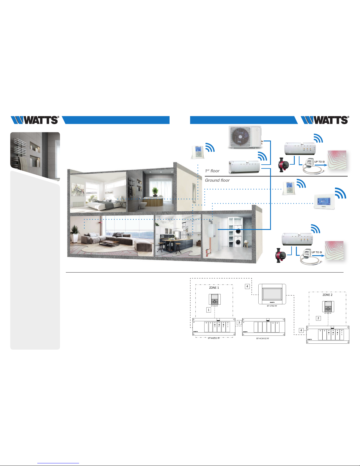
3.1.5 Water floor heating and cooling (multi zones).
Equipments:
• 2 Connecting boxes BT-M6Z02 RF
• 2 (or more) Thermostats BT-D02 RF (or BT-A02 RF, BT-DP02 RF,
BT-D02 RH RF) **
• 1 Connecting box BT-HCM02 RF to drive the heating or cooling mode
• 1 Central Unit BT-CT02 RF
For a correct installation, refer to dedicated user guides of each product, then:
WIRING CONNECTION:
• Connect the actuators (eg. 22C – 22CX series) to the connecting box BT-M6Z02 RF
• Connect the circulating pumps to the related connecting box BT-M6Z02 RF (*)
•
Connect the Hot/Cool Module to the load (eg. A/C system) and to the heating relay
of the boiler
VIRTUAL – RF CONNECTION:
1-2 Pair each thermostat to each zone of the BT-M6Z02 RF.
One thermostat can drive several zones.
3 Pair the BT-HCM02 RF to the BT-M6Z02 RF.
Note – Only one Hot/Cool module BT-HCM02 RF per System (**).
4 Pair in master mode each BT-M6Z02 RF to the Central Unit BT-CT02 RF.
Name the virtual rooms in the BT-CT02 RF and select the hydraulic circuit.
1st floor
Ground floor
**) In application with humidity drier (for system limitation ref. to pag. 33) connect it to the output of Hot/Cool
module for triggering it on/off and managing relative humidity (%). In this case it is necessary to install at
least 1 thermostat BT-D02 RF with Humidity Sensor and locate it in a central area of the installation.
* ) In this application each BT-M6Z02 RF is connected to a circulating pump. DIP SWITCH #1 Configuration:
OFF = LOCAL. In case of an installation with more than one BT-M6Z02 RF connecting box and only 1
circulating pump, DIP SWITCH #1 Configuration: ON = GLOBAL on the BT-M6Z02 RF that drives the
circulating pump (= BT-M6Z02 Master).
boiler
several zones.
NOTE – Only one Hot/Cool module BT-HCM02 RF per Syste m (**).
Name the virtual rooms in the BT-CT02 RF and select the hydraulic ci rcuit.
* In this application each BT-M6Z02 RF is
connected to a circulating pump.
DIP SWITCH #1 Configuration: OFF = LOCAL.
In case of an installation with more than one
BT-M6Z02 RF connecting box and only 1
circulating pump,
DIP SWITCH #1 Configuration: ON = GLOBAL
on the BT-
M6Z02 RF that drives the circulating
pump (= BT-M6Z02 Master).
• Connect the actuators (eg. 22C – 22CX series) to the connecting box BT-M6Z02 RF
• Connect the circulating pumps to the related connecting box BT-M6Z02 RF (*)
• Connect the Hot/Cool Module to the load ( eg. A/C system) and to the heating relay
boiler
several zones.
NOTE – Only one Hot/Cool module BT-HCM02 RF per Syste m (**).
Name the virtual rooms in the BT-CT02 RF and select the hydraulic ci rcuit.
* In this application each BT-M6Z02 RF is
connected to a circulating pump.
DIP SWITCH #1 Configuration: OFF = LOCAL.
In case of an installation with more than one
BT-M6Z02 RF connecting box and only 1
WIRING CONNECT ION:
• Connect the actuators (eg. 22C – 22CX series) to the connecting box BT-M6Z02 RF
• Connect the circulating pumps to the related connecting box BT-M6Z02 RF (*)
• Connect the Hot/Cool Module to the load ( eg. A/C system) and to the heating relay
boiler
VIRTUAL – RF CONNECTION:
1-2 Pair each thermostat to each zone of the BT-M6Z02 RF. One thermostat can drive
several zones.
3 Pair the BT-HCM02 RF to the BT-M6Z02 RF.
NOTE – Only one Hot/Cool module BT-HCM02 RF per Syste m (**).
4 Pair in master mode each BT-M6Z02 RF to the Central Unit BT-CT02 RF.
Name the virtual rooms in the BT-CT02 RF and select the hydraulic ci rcuit.
* In this application each BT-M6Z02 RF is
connected to a circulating pump.
DIP SWITCH #1 Configuration: OFF = LOCAL.
In case of an installation with more than one
BT-M6Z02 RF connecting box and only 1
circulating pump,
• Connect the actuators (eg. 22C – 22CX series) to the connecting box BT-M6Z02 RF
• Connect the circulating pumps to the related connecting box BT-M6Z02 RF (*)
• Connect the Hot/Cool Module to the load ( eg. A/C system) and to the heating relay
boiler
several zones.
NOTE – Only one Hot/Cool module BT-HCM02 RF per Syste m (**).
Name the virtual rooms in the BT-CT02 RF and select the hydraulic ci rcuit.
* In this application each BT-M6Z02 RF is
connected to a circulating pump.
DIP SWITCH #1 Configuration: OFF = LOCAL.
In case of an installation with more than one
BT-M6Z02 RF connecting box and only 1
circulating pump,
DIP SWITCH #1 Configuration: ON = GLOBAL
on the BT-M6Z02 RF that drives the circulating
pump (= BT-M6Z02 Master).
BT-D02 RF
BT-D02 RF
UP TO SIX
BT-M6Z02 RF
BT-HCM02 RT
BT-CT02 RF
BT-M6Z02 RF
UP TO SIX
BT-M6Z02 RF
Page 9

16 17
3.2 Hydraulic Systems without Central Unit
3.2.1 A thermostat (mono zone) managing a boiler or a heat pump.
Equipments:
• 1 Thermostat BT-D02 RF (or BT-D02 or BT-DP02 RF)
• 1 Receiver BT-WR02 HC RF
3.2.2 Single circuit water floor heating, managing actuator and
pump (boiler or heat pump).
Equipments:
• 1 Thermostat BT-D02 RF (or BT-A02 RF, BT-DP02 RF)
• 1 Receiver BT-WR02 RF (or BT-FR02 RF)
For a correct installation, refer to dedicated user guides of each product, then:
WIRING CONNECTION:
• Connect the receiver BT-WR02 HC RF to the heating relay of boiler
(or heat pump).
VIRTUAL – RF CONNECTION:
• Pair the thermostat to the BT-WR02 HC RF
For a correct installation, refer to dedicated user guides of each product, then:
WIRING CONNECTION:
• Connect the receiver BT-WR02 RF (or BT-FR02 RF) to the actuator
(eg. 22C – 22CX series)
VIRTUAL – RF CONNECTION:
• Pair the thermostat to the receiver
A thermostat can control several receivers. In this case, repeat the installation
procedure above.
BT-D02 RF BT-D02 RF
BT-WR02 HC RF
BT-WR02 RF
Page 10

18 19
3.2.3 Water floor heating (only 1 BT-M6Z02 RF).
Equipments:
• 1 Connecting Box BT-M6Z02 RF
• 1 Thermostat BT-D02 RF (or BT-A02 RF or BT-DP02 RF)
For a correct installation, refer to dedicated user guides of each product, then:
WIRING CONNECTION:
• Connect the actuators (eg. 22C – 22CX series) to the connecting box
BT-M6Z02 RF
• Connect the circulating pump to the connecting box BT-M6Z02 RF
• Connect the connecting box BT-M6Z02 RF to the heating relay of the boiler
VIRTUAL – RF CONNECTION:
1 Pair each thermostat to each zone of the BT-M6Z02 RF.
One thermostat can drive several zones
BT-D02 RF
?
UP TO SIX
BT-M6Z02 RF
Page 11

20 21
3.2.4 Water floor heating (multi zones) with several BT-M6Z02 RF
and only 1 boiler.
Equipments:
• 2 Connecting Boxes BT-M6Z02 RF
• 2 Thermostats BT-D02 RF (or BT-A02 RF or BT-DP02 RF)
For a correct installation, refer to dedicated user guides of each product, then:
WIRING CONNECTION:
•
Connect the actuators (eg. 22C – 22CX series) to the connecting boxes BT-M6Z02 RF
• Connect the circulating pumps to the related connecting box BT-M6Z02 RF (*)
• Connect both connecting boxes BT-M6Z02 RF to the heating relay of the boiler
VIRTUAL – RF CONNECTION:
1-2 Pair each thermostat to each zone of the BT-M6Z02 RF.
One thermostat can drive several zones.
3 ** OPTION - Pair the two BT-M6Z02: in this configuration, one BT-M6Z02 RF
(called “Main”) will centralize the information of the other BT-M6Z02 RF
(called “Sub”).
Refer to Centralized Installation of the user guide
BT-D02 RF
BT-D02 RF
1st floor
Ground floor
* In this application each BT-M6Z02 RF is connected to a circulating pump.
DIP SWITCH #1 Configuration: OFF = LOCAL.
** In case of an installation with more than one BT-M6Z02 RF connecting box and only 1 circulating pump,
DIP SWITCH #1 Configuration: ON = GLOBAL on the BT-M6Z02 RF that drives the circulating pump
(= BT-M6Z02 Master) and NO NEED TO WIRE other BT-M6Z02 Slave to the heating relay of the boiler.
WIRING CONNECT ION:
• Connect the actuators (eg. 22C – 22CX series) to the connecting boxes BT-M6Z02 RF
• Connect the circulating pumps to the related connecting box BT-M6Z02 RF (*)
• Connect both connecting boxes BT-M6Z02 RF to the heating relay of the boiler
VIRTUAL – RF CONNECTION:
1-2 Pair each thermostat to each zone of the BT-M6Z02 RF. One thermostat can drive
several zones.
3 ** OPTION - Pair the two BT-M6Z02: In this configuration, one BT-M6Z02-RF (called
“Main”) will centralize the information of th e other BT-M6Z02-RF (called “Sub”).
Refer to Centralized Installation of the user guide
* In this application each BT-M6Z02 RF is
connected to a circulating pump.
DIP SWITCH #1 Configuration: OFF = LOCAL.
** In case of an installation with more than
one BT-M6Z02 RF connecting box and only 1
circulating pump,
DIP SWITCH #1 Configuration: ON = GLOBAL
on the BT-M6Z02 RF that drives the circulating
pump (= BT-M6Z02 Master) and NO NEED TO
WIRE other BT-M6Z02 Slave to the heating
relay of the boiler.
WIRING CONNECT ION:
• Connect the actuators (eg. 22C – 22CX series) to the connecting boxes BT-M6Z02 RF
• Connect the circulating pumps to the related connecting box BT-M6Z02 RF (*)
• Connect both connecting boxes BT-M6Z02 RF to the heating relay of the boiler
VIRTUAL – RF CONNECTION:
1-2 Pair each thermostat to each zone of the BT-M6Z02 RF. One thermostat can drive
several zones.
3 ** OPTION - Pair the two BT-M6Z02: In this configuration, one BT-M6Z02-RF (called
“Main”) will centralize the information of th e other BT-M6Z02-RF (called “Sub”).
Refer to Centralized Installation of the user guide
* In this application each BT-M6Z02 RF is
connected to a circulating pump.
DIP SWITCH #1 Configuration: OFF = LOCAL.
** In case of an installation with more than
one BT-M6Z02 RF connecting box and only 1
circulating pump,
DIP SWITCH #1 Configuration: ON = GLOBAL
on the BT-M6Z02 RF that drives the circulating
pump (= BT-M6Z02 Master) and NO NEED TO
UP TO SIX
BT-M6Z02 RF
UP TO SIX
BT-M6Z02 RF
Page 12

22 23
3.2.5 Water floor heating (multi zones) with several BT-M6Z02 RF
and only 1 boiler.
Equipments:
• 2 Connecting Boxes BT-M6Z02 RF
• 2 (or more) Thermostats BT-D02RF (or BT-A/DP02RF or
BT-D/DP02 RH RF ) **
• 1 Connecting box BT-HCM02 RF to drive the heating or cooling mode
For a correct installation, refer to dedicated user guides of each product, then:
WIRING CONNECTION:
•
Connect the actuators (eg. 22C – 22CX series) to the connecting boxes BT-M6Z02 RF
• Connect the circulating pumps to the related connecting box BT-M6Z02 RF
• Connect the Hot/Cool Module to the load (eg. A/C system) and to the heating relay of the
boiler
VIRTUAL – RF CONNECTION:
1-2 Pair each thermostat to each zone of the BT-M6Z02 RF.
One thermostat can drive several zones
3 Pair the two BT-M6Z02: In this configuration, one BT-M6Z02-RF (called “Main”)
will centralize the information of the other BT-M6Z02-RF (called “Sub”).
Refer to Centralized Installation of the user guide
4 Pair in slave mode the BT-HCM02 RF to the BT-M6Z02 RF master.
* In this application each BT-M6Z02 RF is connected to a circulating pump.
DIP SWITCH #1 Configuration: OFF = LOCAL. In case of an installation with more than one BT-M6Z02 RF
connecting box and only 1 circulating pump, DIP SWITCH #1 Configuration: ON = GLOBAL on the
BT-M6Z02 RF that drives the circulating pump (= BT-M6Z02 Master)
** In application with humidity drier (for system limitation ref. to pag. 33) connect it to the output of Hot/Cool
module for triggering it on/off and managing relative humidity (%). In this case it is necessary to install at
least 1 thermostat BT-D02 RF with Humidity Sensor and locate it in a central area of the installation.
Note: one humidity drier per System – refer to SYSTEM LIMITATIONS (pag. 33).
BT-D02 RF
BT-D02 RF
WIRING CONNECTI ON:
• Connect the actuators (eg. 22C – 22CX series) to the connecting boxes BT-M6Z02 RF
• Connect the circulating pumps to the related connecting box BT-M6Z02 RF
• Connect the Hot/Cool Module to the load (eg. A/C system)
VIRTUAL – RF CONNECTION:
1-2 Pair each thermostat to each zone of the BT-M6Z02 RF. One thermostat can d rive
several zones
3 Pair the two BT-M6Z02: In this configuration, one BT-M6Z02-RF (called “Main”) will
centralize the information of the other BT-M6Z02-RF (called “Sub”).
Refer to Centralized Installation of the user guide
4 Pair in slave mode the BT-HCM02 RF to the BT-M6Z02 RF master
BT-HCM02 RF
UP TO SIX
BT-M6Z02 RF
UP TO SIX
BT-M6Z02 RF
Page 13

24 25
For a correct installation, refer to dedicated user guides of each product, then:
WIRING CONNECTION:
• Connect each receiver (BT-FR02 RF, BT-PR02 RF and/or BT-WR02 RF)
to related electrical device
VIRTUAL – RF CONNECTION:
• Create the virtual rooms in the Central Unit BT-CT02 RF
1 Pair each thermostat as a Heating device in each virtual room in the
Central Unit BT-CT02 RF
2-3-4 Pair each receiver in each virtual room of the Central Unit BT-CT02 RF
as a Heating device and select electrical heating mode in the Heating
Parameter
BT-CT02 RF
BT-D02 RF
3.3 Electrical heating System
3.3.1 One (or several) electrical heaters in multi zones with
centralized remote control.
Equipments:
• 1 (or more) Thermostat BT-D02 RF (or BT-A02 RF or BT-DP02 RF)
• Several receivers : BT-FR02 RF, BT-PR02 RF or BT-WR02 RF
• 1 Central Unit BT-CT02 RF
For a correct installation, refer to dedicated user guides of each product, then:
WIRING CONNECTI ON:
• Connect each receiver (BT-FR02 RF, BT-PR02 RF and/or BT-WR02 RF) to related electrical
device
VIRTUAL – RF CONNECTION:
• create the virtual rooms In the Cent ral Unit BT-CT02 RF
1 Pair each thermostat as a Heating device in each virtual room in the Centr al Unit
BT-CT02 RF
2-3-4 Pair each receiver i n each virtual room of the Central Uni t BT-CT02 RF as a Heating
device and select electrical heating mode in the Heating Parameter
BT-WR02 HC RF
BT-PR02 RF
BT-FR02 RF
BT-WR02 HC RF
Page 14

26 27
For a correct installation, refer to dedicated user guides of each product, then:
WIRING CONNECTION:
• Connect each receiver (BT-FR02 RF, BT-PR02 RF and/or BT-WR02 RF) to
related electrical device
VIRTUAL – RF CONNECTION:
1 Pair the thermostat to the receiver
2-3-4 In case of several receivers e linked to the same thermostat, make
again the operation above for each receiver
3.3.2 One (or several) electrical heaters (1 zone).
Equipments:
• 1 Thermostat BT-D02 RF (or BT-A02 RF or BT-DP02 RF)
• Several Receivers: BT-FR02 RF, BT-PR02 RF or BT-WR02 RF
BT-D02 RF
BT-PR02 RF
BT-FR02 RF
WIRING CONNECT ION:
• Connect each receiver (BT- FR02 RF, BT-PR02 RF and/or BT-WR02 RF) to related electrical
device
VIRTUAL – RF CONNECTION:
1 Pair the thermostat to the receiver
2-3-4 In case of several receivers e linked to the same thermostat, make again the operation
above for each receiv er
WIRING CONNECT ION:
• Connect each receiver (BT- FR02 RF, BT-PR02 RF and/or BT-WR02 RF) to related electrical
device
VIRTUAL – RF CONNECTION:
1 Pair the thermostat to the receiver
2-3-4 In case of several receivers e linked to the same thermostat, make again the operation
above for each receiv er
• Connect each receiver (BT- FR02 RF, BT-PR02 RF and/or BT-WR02 RF) to related electrical
device
above for each receiv er
BT-WR02 HC RF
BT-WR02 HC RF
Page 15

28 29
For a correct installation, refer to dedicated user guides of each product, then:
WIRING CONNECTION:
• Connect BT-M6Z02 RF to the actuators (eg. 22C – 22CX series)
•
Connect the circulating pump to the connecting box BT-M6Z02 RF (and boiler if needed)
• Connect the receivers BT-WR02 HC RF to the boiler
VIRTUAL – RF CONNECTION:
1 Pair each thermostat to each zone of the BT-M6Z02 RF. One thermostat can
drive several zones
2 Pair in master mode each BT-M6Z02 RF to the BT-CT02 RF. Name the virtual
rooms in the BT-CT02 RF and select the hydraulic circuit.
Devices configuration:
go in the zone, select the information menu, select the receiver and the hy-
draulic type, then the hydraulic circuit (refer to HYDRAULIC SYSTEM PAIRING
chapter on Central Unit user guide).
3. Pair the BT-WR02 HC RF (or BT-WR02 RF if driving a pump) receivers to the
BT-CT02 RF as a hydraulic circuit then selects the hydraulic circuit.
4. Option : Pair as Heating Device a thermostat in each virtual room created in the
BT-CT02 RF containing a hydraulic radiator
5. Pair as Heating Device each BT-TH02 RF in each virtual room created in the BT-CT02 RF by selecting the hydraulic
circuit. We can pair several BT-TH02 RF in the same room. Devices configuration: go in the zone, select the informa-
tion menu, select the receiver and the hydraulic type, then the hydraulic circuit (refer to HYDRAULIC SYSTEM PAIRING
chapter on Central Unit user guide).
3.4 Mixed System - combining several modes
of heating with centralized remote control
3.4.1 Water floor heating and hydraulic radiator.
Equipments:
• Connecting Box BT-M6Z02 RF
• Thermostats BT-D02 RF
(or BT-A02 RF, BT-DP02 RF, BT-D02 RH RF, BT-DP02 RH RF)
• Central Unit BT-CT02 RF
• Receiver BT-WR02 HC RF (or BT-WR02 RF) to control the pumps
• 1 (or more)Thermostatic Heads BT-TH02 RF
BT-CT02 RF
BT-D02 RF
BT-D02 RF
BT-WR02 HC RF
BT-TH02 RF
UP TO SIX
BT-M6Z02 RF
BT-WR02 HC RF
Page 16

30 31
For a correct installation, refer to dedicated user guides of each product, then:
WIRING CONNECTION:
• Connect BT-M6Z02 RF to the actuators (eg. 22C – 22CX series)
• Connect the circulating pump to the connecting box BT-M6Z02 RF (*)
• Connect the receivers BT-WR02 HC RF to the heating relay of the boiler
• Connect the receivers BT-WR02 RF (or BT-FR02 RF) to electrical heaters and
to the pump (if needed – option)
3.4.2 Water floor heating, hydraulic radiator and electrical heaters.
Equipments:
• Connecting Box BT-M6Z02 RF
• Thermostats BT-D02 RF (or BT-A02 RF, BT-DP02 RF, BT-D02 RH RF,
BT-DP02 RH RF)
• Central Unit BT-CT02 RF
• Receivers BT-WR02 HC RF to control the boiler
• Receivers BT-WR02 RF (or BT-FR02 RF) to control the pumps (if needed)
• Receivers BT-WR02 RF (or BT-FR02 RF) to control the electrical heaters
• Thermostatic Heads BT-TH02 RF
VIRTUAL – RF CONNECTION:
Zone 1 1 Pair each thermostat to each zone of the BT-M6Z02 RF.
One thermostat can drive several zones.
2 Pair in master mode each BT-M6Z02 RF to the Central Unit BT-CT02 RF.
Name the virtual rooms in the BT-CT02 RF and select the hydraulic circuit.
BT-WR02 HC RF
BT-WR02 HC RF
Option
ZONE 1
BT-D02 RF
BT-TH02 RF
ZONE 2
BT-D02 RF
ZONE 3
BT-WR02 HC RF
BT-CT02 RF
UP TO SIX
BT-M6Z02 RF
Page 17

32 33
System limitations
• Only one Hot-Cool module BT-HCM02 RF per System – 1 output only
for humidity drier
• 4 hydraulic circuits per System
• Only zones containing only electrical heaters can do heating when the
System is in cooling mode
• Mix different modes of heating in the same room is not recommended
as the regulations embedded in each receiver are not synchronized
• With a Central Unit BT-CT02 RF, it is highly recommended to use devices paired in hydraulic circuit directly on the BT-CT02 RF. Output usage
of BT-M6Z02 RF and BT-HCM02 RF is only possible on small System
(Only 1 BT-M6Z02 RF and 1 BT-HCM02 RF)
BT-CT02 RF software update
On www.wattswater.eu homepage, you can find files allowing updating the
software of the Central Unit BT-CT02 RF. The procedure should be performed while
the BT-CT02 RF is plugged to the 230V wall support.
• Unzip in a microSD the 3 files (wifi.ini, wifi.hex, update.bin)
• Insert the microSD
• Press on Update Firmware in the installation menu
• Wait the end of the software Update procedure and wait at least 1mn
before removing the microSD
Configuration of the remote control
of the central
Except the installation configuration, all the functions of the Central Unit are
available on:
• The web site www.wattswater.eu
• On Watts Vision application available on Apple store (iOS)
• On Watts Vision application available on Play store (Android)
The remote control configuration should be performed in 3 steps after configuration
of you heating and cooling system.
1 Connect the central to a wifi router. Menu Installation/wifi. The connec-
tion can be manual or automatic. When the wifi connection succeeds,
the wifi menu displays 1/2 status and a green flag.
2 From the web site or the application, create an account with your email
and a password
3 Link your central to your account. In the application, request the send-
ing of a pairing code on your mail box. Enter the code in the wifi menu.
4 After a few minutes, your central should be displayed in the application.
The wifi menu of the central should display 2/2 status.
More detailed explanation available on BT-CT02 RF dedicated user guide.
Devices configuration: go in the zone, select the information menu,
select the receiver and the hydraulic type, then the hydraulic circuit
(refer to HYDRAULIC SYSTEM PAIRING chapter on Central Unit
user guide).
3 Option: Pair the BT-WR02 RF receiver to the BT-M6Z02 RF as a
slave link.
Zone 2 4 Option: Pair a thermostat in each virtual room created in the BT-
CT02 RF containing a radiator
5 Pair each BT-TH02 RF in each virtual room created in the BT-CT02
RF by selecting the hydraulic circuit. We can pair several BT-TH02
RF in the same room
Devices configuration: go in the zone, select the information
menu, select the receiver and the hydraulic type, then the hydraulic
circuit (refer to HYDRAULIC SYSTEM PAIRING chapter on Central
Unit user guide).
Main Circuit
6 Pair the BT-WR02 HC RF receiver to the BT-CT02 RF as a hydraulic
circuit then select the hydraulic circuit.
Zone 3 7 Pair thermostat in virtual room in the Central Unit BT-CT02 RF
8 Pair each receiver in each virtual room of the Central Unit BT-CT02
RF by selecting the electrical device.
33
WIRING CONNEC TION:
• Connect BT-M6Z02 RF to the actuators (eg. 22C – 22CX series)
• Connect the circulating pump to the connecting box BT-M6Z02 RF (*)
• Connect the receivers BT-WR HC02 RF to the heating relay of the boiler
• Connect the receivers BT- WR 02 RF (or BT-FR02 RF) to electri cal heaters and to the
pump (if needed – option)
VIRTUAL – RF CONNECTION:
in the BT-CT02 RF and select the hydraulic circuit
Devices configuration: go in the zone, select the information menu, select the receiver and the
hydraulic type, then the hydraulic circuit (refer to HYDRAULIC SYSTEM PAIRING chap ter on
Central Unit user guide).
circuit. We can pair several BT-TH02 RF in the same room
Devices configuration: go in the z one, select the information menu, select the receiver and t he
hydraulic type, then the hydraulic circuit (refer to HYDRAULIC SYSTEM PAIRING chap ter on
Central Unit user guide).
circuit.
device.
Option
* DIP SWITCH #1
Configuration :
OFF = LOCAL
* DIP SWITCH #1 Configuration : OFF = LOCAL
BT-WR02 HC RF
BT-WR02 HC RF
BT-WR02 HC RF
Page 18

34 35
Devices Symptom Remedy (Try 1. In case of failure, try 2. etc…)
Wifi central unit No connection on Wifi network. 1. Check that you have the last software on the central unit,
Status 0/2. update available on www.wattswater.eu if needed.
2. Reduce the range between the central and your Wifi Router.
3. Check your Wifi hotspot with an other wifi device.
Open network are not supported, nor configuration requesting a registration on a web page. Only Channels 1 to 11
in 2,4GHz are supported. WPA2 encryption key type is
recommended. WPA auto or WPA mixed mode configured on
the wifi router are not supported (Please force an encryption
key type on the router, WPA2 is recommended).
4. Trigger first the research network (Check Protected Access
Key Type/ Password). If your desired WiFi network is still not
displayed, enter the WiFi settings manually.
Wifi central unit No connection on the server. 1. Check that you have the last software on the central unit,
Status 1/2. update available on www.wattswater.eu if needed.
2. Request a new twining code on the application, via www.
wattswater.eu or directly on the website http://smarthome.
wattselectronics.com.
3. Switch OFF/ON the central unit.
4. Wait for getting a wifi connection (status 1/2) and a
valid IP address, then wait 1 additional minute.
5. Enter the new twining code and wait 30s.
6. Check that the status becomes 2/2 (require to refresh the
screen).
7. If the status remains 1/2, check the wifi connection.
8. If the status is 0/2, please refer to the «No connection on Wifi
network. Status 0/2» symptom in the FAQ.
Wifi central unit No Wifi function. 1. Check that your central supports the wifi.
2. Format a Micro SD card in FAT32 and put the wifi.ini and wifi.
hex files on the SD card.
3. Insert the Micro SD card and switch OFF/ON the central unit.
4. Wait at least 1mn and check that wifi icon is recovered.
Wifi central unit RF lost and RF error alarms diplayed 1. Check Power supply or battery on receiver.
and any devices on the central unit. Alarm on receiver. 2. Modify setpoint on the thermostat or press any button on
(receiver or thermostat) the device.
3. Switch OFF/ON the central unit.
4. Reinstall the device: Delete the device in the central, reset the
device. (See the the device manual to know how to proceed)
then pair the device.
Wifi central unit and No reception of email for account 1. Check Spam mail box
application creation and central unit pairing 2. Use your personal mailbox instead of company server or any
kind of private server
Wifi central unit and Rooms do not appear in the application 1. Check Wifi connection on the central. Status 2/2 is required.
application 2. Check that you have the last sofware on the central unit,
update available on www.wattswater.eu if needed
3. Make sure that you use the last version of the application on
your smartphone
Devices Symptom Remedy (Try 1. In case of failure, try 2. etc…)
Wifi central unit and Pairing failure between the 1. Check compatibility: only Watts Vision devices are compatibles.
any devices device and the central unit update available on www.wattswater.eu if needed.
(receiver or thermostat)
2. Check the compatibility of the configuration:
for heating, the device measuring the temperature should be
paired first in the room.
3. Reset the device.
4. Check RF range. The device needs to be not too closed or
too far from the the central unit. RF repeater may be useful in
case pf long distance.
BT-TH02 RF Bad regulation 1. Check compatibility of the thermostatic head with the valve.
2. In case of program usage, avoid a too big difference between
the eco setpoint and the comfort setpoint.
BT-TH02 RF Alarm on the boiler 1. Activate the bypass function on at least one BT-TH02 RF
Wifi central unit and There is no communication between Check whether special characters or mutated vowels are used
any devices some devices and the central unit after in the name of zones / rooms or devices. In such case there
(receiver or thermostat)
a software update on the central unit. might be a malfunction if a central unit with initial software ver-
sion lower than 3.00 is updated to software higher than 3.00.
Remedy: remove the special characters and rename the mu-
tated vowels (ae, oe and ue instead of ä, ö and ü etc.) in the
respective names.
RF-Thermostat and In the extended parameter menu some Reset in the extended parameter menu:
any devices (receiver, functions are no longer available. Parameter # 36 « CLr .. « and carry out the reset by holding down
connecting box,
Cause: If a radio thermostat is not paired the (OK) button for several seconds until the display changes.
central unit, ...) with a radio receiver BT-FR02 RF, then ATTENTION: By the reset the radio pairing with other devices
e.g. in parameter # 20 the two options is canceled. This must be carried out again.
« FLr « and « FLL « are no longer available.
Wifi central unit and
The error message «Device already installed»
Check that the device has been accidentally selected incorrectly.
any devices appears during the radio initialization If necessary, the device can be deleted and reassigned
(receiver or thermostat)
(radio pairing) with the central unit. via the menu «Delete a device».
Problems and solutions
Page 19

WV-AG-IT-W-UK-01-18-Rev.1 © 2018 Watts
Watts Industries Italia S.r.l.
Sede operativa: Via Brenno, 21 - 20853 Biassono (MB), Italia - Tel: +39 039 49.86.1 - Fax: +39 039 49.86.222
Sede legale: Frazione Gardolo, Via Vienna, 3 - 38121 Trento (TN), Italia - Cod. Fisc. 00743720153 - Partita IVA n° IT 01742290214
Società unipersonale del gruppo Watts Italy Holding Srl - soggetta a direzione e coordinamento ai sensi degli artt. 2497 e s.m.i. del C.C.
 Loading...