Watts TK-99E User Manual

Watts TK-99E
Backflow Preventer Test Kit
IS-TK-99E
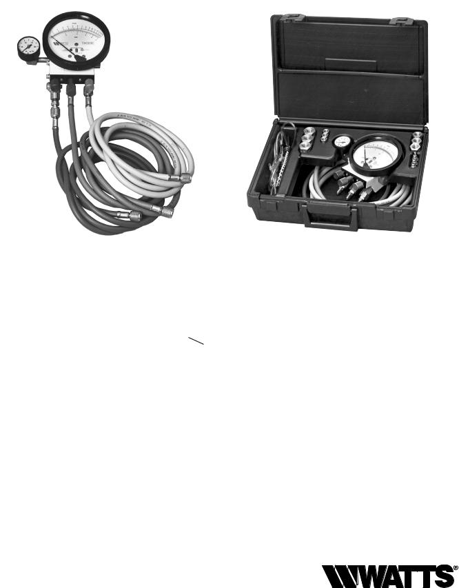
Designed for operator convenience and rugged reliability in a compact package. The Watts TK-99E offers the latest in gauge technology in a durable custom-fitted case with room for tools.
Features:
•Lightweight body for durability & chemical resistance.
•Color-coded valves and hoses for ease of use.
•Large anti-parallax dial which indicates descending measurement, accurate to ± 1 percent of full scale.
•Replaceable hose filter and valve stem seals for field reliability.
•Top mounted drain/purge valves and conveniently located line pressure gauge.
•Complete kit contains gauge with colorcoded valves and hoses, hose adapter, shock cord for easy mounting and purge hose encased in a durable case with room for tools.
•Forward needle valve positions for easy access.
Caution: To avoid freeze damage to the test kit it should be stored in a dry warm area when not in use.
Bleed Valve B
Bleed Valve A
C
A B C A B
Connections |
Needle Valves |
|
Specifications:
•Maximum working pressure - 200 psig
•Maximum working temperature - 200°F
•Gauge - 4.5" diameter face, dual scale 0-15 psid and 0-1 kg/cm2, ± 1% accuracy full scale
•Test valves - Three needle valves
•Pressure gauge - 0-200psi system gauge
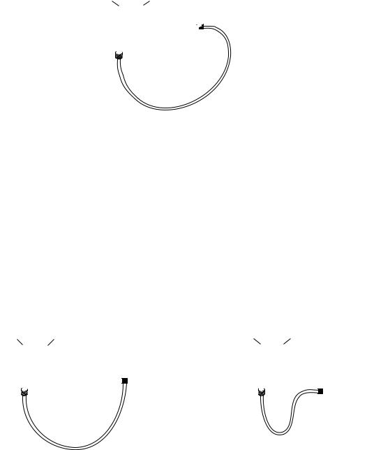
•Hoses - Three 6 foot color-coded hoses with female threaded swivel couplings.
•Adapter - Three 3⁄4" x 1⁄4" bushings Three 1⁄2" x 1⁄4" bushings Three 3⁄8" x 1⁄4" bushings Three 1⁄4" Flared fittings
•One shock cord.
•One moisture resistant instruction guide
•One lightweight durable carrying case

Test Procedure for Spill Resistant Vacuum Breaker
Note: For both of the following tests the test kit must be held at the same level as assembly being tested.
A. Before starting test, all needle valves and bleed valves on test kit must be closed. B. Flush test cocks before test.
Bleed Valve A |
Bleed Valve B |
Test No. 1 and 2
008QT shown
Test No. 1 - Differential Test
Requirement: Differential pressure across check must be 1.0 psid or above
Step 1: Remove two screws on top of hood then remove hood.
Step 2: Install hose between test cock and connection “A” high side (red) of test kit.
Step 3: Open test cock then open bleed valve “A” on top of test kit. Bleed air from hose then close bleed valve “A” on top of test kit.
Step 4: Open needle valve “A” on high side (red) of test kit.
Step 5: Close shutoff valve No. 2 then shut off valve No. 1 on test assembly.
Step 6: Slowly unscrew bleed screw on spill resistant vacuum breaker body to relieve pressure down stream of check (about 3 turns).
Step 7: When dripping from bleed screw stops and psid needle on gauge stabilizes, record the differential pressure.
Test No. 2 - Air Inlet - Vent Opening
Requirement: Air inlet must start to open when supply pressure is 1.0psi or above. Air inlet must be fully open when supply pressure is atmospheric.
Step 8: Slowly open needle valve “C” bypass (yellow) until psid gauge reads 1.0psid then close needle valve “C” bypass (yellow) holding pressure at 1.0psid.
Step 9: Visually inspect that the vent on top is slightly open, about 1⁄32" or more, to pass test.
Step 10: Open needle valve “C” bypass (yellow) fully until dripping from connection “C” stops.
Step 11: Visually inspect that the vent is fully open to pass test.
Step 12: Replace hood and two screws on top of assembly. Step 13: Restore valve to original working condition.
Note: After test, all valves on test kit must be fully open and hose removed to prevent damage to test kit.
Test Procedure for Pressure Type Vacuum Breaker
NOTE: For both of the following tests the test kit must be held at the same level as assembly being tested.
A. Before starting test all needle valves and bleed valves must be closed. B. Flush test cock #2 and #1.
Bleed Valve B |
Bleed Valve A |
Bleed Valve B |
|
Bleed Valve A |
|
||
Test Cock No. 2 |
|
|
|
Test Cock |
|
|
Test Cock No. 2 |
No. 1 |
|
Test Cock |
|
|
|
||
|
|
|
|
Test No. 1 |
|
No. 1 |
Test No. 2 |
|
|
||
800M4-QT shown |
|
|
800M4-QT shown |
Test No. 1 - Air Inlet
Requirement: Air inlet must start to open when down stream pressure is 1.0psi or above.
Step 1: Removetwoscrewsontopofhoodandremovehood.
Step 2: Install hose between test cock No. 2 and connection “A” on high side (red) on test kit.
Step 3: Open test cock No. 2 and needle valve “A” high side (red) on test kit.
Step 4: Open bleed valve “A” on top of test kit. Bleed air from hose. Then close bleed valve “A” on top of test kit.
Step 5: Close shutoff valve No. 2 then shutoff valve No. 1.
Step 6: Slowly open needle valve “C” bypass (yellow) just as air inlet opens. Record differential pressure.
Step 7: Close test cock No. 2 and remove hose. Step 8: Close needle valve “C” bypass (yellow). Step 9: Open shutoff valve No. 1.
Test No. 2 - Test Check Valve Pressure Drop
Requirement: Supply pressure drop must be 1.0psid or above when water flow stops from test cock No. 2.
Step 10: Install hose between test cock No. 1 and connection “A” high side (red) on test kit.
Step 11: Open test cock No. 1 and bleed valve “A” on top of test kit. Open bleed valve “A” on top of test kit and bleed air from hose. Shutoff bleed valve “A” on top of test kit.
Step 12: Close shutoff valve #1.
Step 13: Open test cock No. 2. When flow of water out of test cock No. 2 stops, the differential reading is the pressure drop record.
Step 14: Close test cock No. 1 and test cock No. 2.
Step 15: Replace hood and two screws on top of hood. Open shutoff valves Nos. 1 then 2.
2
 Loading...