

Page 1

CLS
User’s Guide
Watlow Controls
1241 Bundy Blvd.
Winona, MN 55987
Customer Service
Phone: (800) 414-4299
Fax: (800) 445-8992
Technical Support
Phone: (507) 494-5656
Fax: (507) 452-4507
Email: wintechsupport@watlow.com
Part No. 21952-00. Revision 3.2
October 1996
Page 2

Copyright © 1996
Watlow Anafaze
Information in this manual is subject to change without notice. No part of this publication may be
reproduced, stored in a retrieval system, or transmitted in any form without written permission
from Watlow Anafaze.
Warranty
Watlow Anafaze, Incorporated warrants that the products furnished under this Agreement will be
free from defects in material and workmanship for a period of three years from the date of shipment. The Customer shall provide notice of any defect to Watlow Anafaze, Incorporated within one
week after the Customer's discovery of such defect. The sole obligation and liability of Watlow
Anafaze, Incorporated under this warranty shall be to repair or replace, at its option and without
cost to the Customer, the defective product or part.
Upon request by Watlow Anafaze, Incorporated, the product or part claimed to be defective shall
immediately be returned at the Customer's expense to Watlow Anafaze, Incorporated. Replaced or
repaired products or parts will be shipped to the Customer at the expense of Watlow Anafaze,
Incorporated.
There shall be no warranty or liability for any products or parts that have been subject to misuse,
accident, negligence, failure of electric power or modification by the Customer without the written
approval of Watlow Anafaze, Incorporated. Final determination of warranty eligibility shall be
made by Watlow Anafaze, Incorporated. If a warranty claim is considered invalid for any reason,
the Customer will be charged for services performed and expenses incurred by Watlow Anafaze,
Incorporated in handling and shipping the returned unit.
If replacement parts are supplied or repairs made during the original warranty period, the warranty
period for the replacement or repaired part shall terminate with the termination of the warranty
period of the original product or part.
The foregoing warranty constitutes the sole liability of Watlow Anafaze, Incorporated and the Customer's sole remedy with respect to the products. It is in lieu of all other warranties, liabilities, and
remedies. Except as thus provided, Watlow Anafaze, Inc. disclaims all warranties, express or
implied, including any warranty of merchantability or fitness for a particular purpose.
Please Note: External safety devices must be used with this equipment.
Page 3

CLS User’s Guide Contents
Contents
Overview 1
System Diagram.....................................................................2
Parts List ...............................................................................2
Safety .....................................................................................3
Introduction 5
Specifications ........................................................................7
Analog Inputs ..................................................................7
Digital Inputs ..................................................................9
User-Selectable Digital Outputs .....................................9
System Digital Outputs....................................................9
Analog Outputs................................................................10
Miscellaneous Specifications ................................................11
Physical Dimensions .......................................................11
Installation 13
Precautions and Warnings ....................................................14
Recommended Tools ............................................................15
Panel Hole Cutters ..........................................................15
Other Tools .....................................................................15
CLS Mounting Procedure .....................................................16
Mounting Environment ...................................................16
Steps: ...............................................................................16
TB-18 Mounting Instructions ...............................................17
TB-50 Mounting Instructions ...............................................18
General Wiring Recommendations .......................................20
Grounding .......................................................................21
Thermocouple Wiring .....................................................22
Input Wiring ....................................................................22
Output Wiring .................................................................23
Communications Wiring .................................................23
Wiring: Noise Suppression ...................................................24
General Wiring .....................................................................25
Power Wiring and Controller Test ..................................25
Outputs ..................................................................................27
PID Control and Alarm Output Connections 2................30
Watchdog Timer .............................................................30
TB-18 Connections .........................................................31
TB-50 Connections .........................................................32
i
Page 4

Contents CLS User’s Guide
Inputs ....................................................................................34
Input Scaling ...................................................................34
4 and 8 CLS Scaling Values ...........................................35
16 CLS Scaling Values ...................................................38
Scaling and Calibration ...................................................39
T/C Inputs .......................................................................39
RTD Inputs (4 and 8 CLS only) ......................................40
Current Inputs .................................................................41
Voltage Inputs .................................................................41
Unused Inputs .................................................................41
Back Terminal Block Connections .................................42
Serial Communications .........................................................42
RS-232 Interface .............................................................43
RS-485 Interface .............................................................43
Using the CLS 49
Introduction ...........................................................................49
Front Panel ............................................................................50
Front Panel Keys .............................................................50
Displays ................................................................................53
Bar Graph Display ..........................................................53
Single Loop Display .......................................................54
Alarms .............................................................................56
Job Display ...........................................................................57
Operator Menus ....................................................................58
Change Setpoint ..............................................................58
Manual/Automatic Control .............................................58
Ramp/Soak ......................................................................60
Setup 61
How to Enter the Setup Menus? .....................................61
How to edit a menu? .......................................................61
Set up Global Parameters Menu ...........................................63
Load a Job .......................................................................64
Save Setup to Job ............................................................64
Job Select Inputs .............................................................65
Job Select Input Polarity .................................................65
Output Override Digital Input .........................................66
Output Override Input Polarity .......................................66
Start-up Alarm Delay ......................................................66
Keyboard Lock Status .....................................................67
Power-Up Output Status .................................................67
Controller Address ..........................................................67
Communications Baud Rate ............................................68
ii
Page 5

CLS User’s Guide Contents
Communications Protocol ...............................................68
Communications Error Checking ...................................68
AC Line Frequency .........................................................69
Digital Output Polarity ....................................................69
EPROM Information .......................................................69
Set up Loop Input .................................................................70
Input Type .......................................................................71
Pulse Sample Time .........................................................72
Loop Name .....................................................................72
Input Units ......................................................................72
Input Reading Offset .......................................................73
Linear Scaling Menus .....................................................73
Display Format ...............................................................75
High Process Value .........................................................75
High Reading ..................................................................76
Low Process Value .........................................................76
Low Reading ...................................................................76
Input Filter ......................................................................77
Set up Loop Control Parameters ...........................................78
Heat or Cool Control PB .................................................79
Heat or Cool Control TI ..................................................79
Heat or Cool Control TD ................................................79
Heat or Cool Output Filter ..............................................80
Heat and Cool Spread .....................................................80
Set up Loop Outputs .............................................................81
Enable/Disable Heat or Cool Outputs .............................82
Heat or Cool Output Type ..............................................82
Heat or Cool Cycle Time ................................................83
SDAC Menus ........................................................................83
SDAC Mode ...................................................................83
SDAC High Value ..........................................................84
SDAC Low Value ...........................................................84
Heat or Cool Output Action ............................................84
Heat or Cool Output Limit ..............................................85
Heat or Cool Output Limit Time ....................................85
Heat or Cool Output Override ........................................85
Heat or Cool Nonlinear Output Curve ............................86
Set up Loop Alarms ..............................................................87
Alarm Types ...................................................................87
High Process Alarm Setpoint ..........................................90
High Process Alarm Type ...............................................90
High Process Alarm Output Number ..............................90
Deviation Band Value .....................................................91
High Deviation Alarm Type ...........................................91
iii
Page 6

Contents CLS User’s Guide
High Deviation Alarm Output Number ..........................91
Low Deviation Alarm Type ............................................92
Low Deviation Alarm Output Number ...........................92
Low Process Alarm Setpoint ..........................................92
Low Process Alarm Type ...............................................93
Low Process Alarm Output Number ..............................93
Alarm Deadband .............................................................93
Alarm Delay.....................................................................94
Manual I/O Test ....................................................................95
Digital Input Testing .......................................................95
Test Digital Output .........................................................96
Toggle Digital Output .....................................................96
Keypad Test ....................................................................96
PID Tuning and Control 97
Introduction ...........................................................................97
Control Modes ......................................................................98
On/Off Control ................................................................98
Proportional Control .......................................................98
Proportional and Integral Control ...................................99
Proportional, Integral and Derivative Control ................100
Control Outputs ...............................................................100
Digital Output Control Forms .........................................100
Setting Up and Tuning PID Loops .......................................103
Proportional Band (PB) Settings .....................................103
Integral Term (TI) Settings .............................................104
Derivative Term (TD) Settings .......................................104
General PID Constants by Application .................................105
Proportional Band Only (P) ............................................105
Proportional with Integral (PI) ........................................105
PI with Derivative (PID) .................................................105
iv
Troubleshooting 107
No Key Reset ..................................................................107
Returning your Unit ........................................................108
Troubleshooting Stand-Alone Systems ................................108
Checking an Analog Input ..............................................108
Checking Digital I/O .......................................................109
Checking Computer Supervised Systems .............................110
Computer Problems ........................................................110
Software Problems ..........................................................111
Changing the EPROM ....................................................111
Page 7

CLS User’s Guide Contents
Linear Scaling Examples 115
Example 1 .............................................................................115
Example 2 .............................................................................116
Example 3 .............................................................................117
Appendix A: Ramp Soak 119
Introduction ...........................................................................119
R/S Features ....................................................................119
Specifications ..................................................................120
Configuring Ramp/Soak .......................................................120
Setting the R/S Time Base ..............................................121
Editing R/S Parameters ...................................................121
Choosing a Profile to Edit ...............................................121
Copying the Setup from Another Profile ........................122
Editing the tolerance Alarm Time ..................................122
Editing the Ready Setpoint .............................................123
Editing the Ready Event States .......................................123
Choosing an External Reset Input ..................................124
Editing a Segment ...........................................................124
Setting Segment Time .....................................................124
Setting a Segment Setpoint .............................................125
Configuring Segment Events ..........................................125
Editing Event Outputs .....................................................126
Changing Event States ....................................................126
Editing Segment Triggers ...............................................126
Assigning an Input to a Trigger ......................................127
Changing a Trigger’s True State .....................................127
Latching or Unlatching a Trigger ...................................127
Setting Segment Tolerance .............................................128
Ending a Profile ..............................................................128
Repeating a Profile ..........................................................128
Using Ramp/Soak .................................................................129
Assigning a profile to a loop ...........................................129
Assigning a Profile to a Linear Input Loop ....................130
Running a Profile ............................................................131
Ramp/Soak Displays .......................................................131
Holding a Profile or Continuing from Hold ....................134
Resetting a profile ...........................................................135
Appendix B: Enhanced Process Control 137
Enhanced Process Control Menus ........................................138
v
Page 8

vContents CLS User’s Guide
Process Variable Retransmit .................................................139
Setting Up a PV Retransmit ............................................139
PV Retransmit Menus .....................................................140
Cascade Control ....................................................................143
Setting Up Cascade Control ............................................143
Cascade Control Menus ..................................................144
Ratio control .........................................................................147
Setting Up Ratio Control ................................................147
Ratio Control Menus .......................................................148
Remote Analog setpoint ........................................................149
Differential Control ...............................................................149
Typical Applications .............................................................150
Process Variable Retransmit ...........................................150
Cascade Control ..............................................................153
Ratio Control ...................................................................156
Remote Setpoint ..............................................................158
Differential Control .........................................................159
Glossary 163
Page 9

Overview
Overview
This manual describes how to install, setup, and operate a 4CLS, an
8CLS, or a 16CLS. Included are seven chapters, two Appendices, and a
glossary of terms. Each chapter covers a different aspect of your control
system and may apply to different users. The following describes the
chapters and their purpose.
•
Introduction: Gives a general description of the CLS and its related
specifications.
•
Installation: Describes how to install the CLS and its peripheral
devices.
•
Using the CLS: Provides an overview of operator displays used for
system monitoring.
•
Setup: Describes all the setup displays for the controller, and how to
access them.
•
Tuning and Control: Explains PID control and provides tips for
tuning your system.
•
Troubleshooting: Gives some basic guidelines for solving control
problems.
•
Linear Scaling Examples: Provides an example configuring a pres-
sure sensor, and one configuring a flow sensor.
•
Appendix A: Ramp and Soak. This section explains how to setup
and use Ramp/Soak profiles in your application.
•
Appendix B: Enhanced Process Control. This appendix describes
optional process variable retransmit and cascade control features.
CLS User’s Guide 1
Page 10
Overview
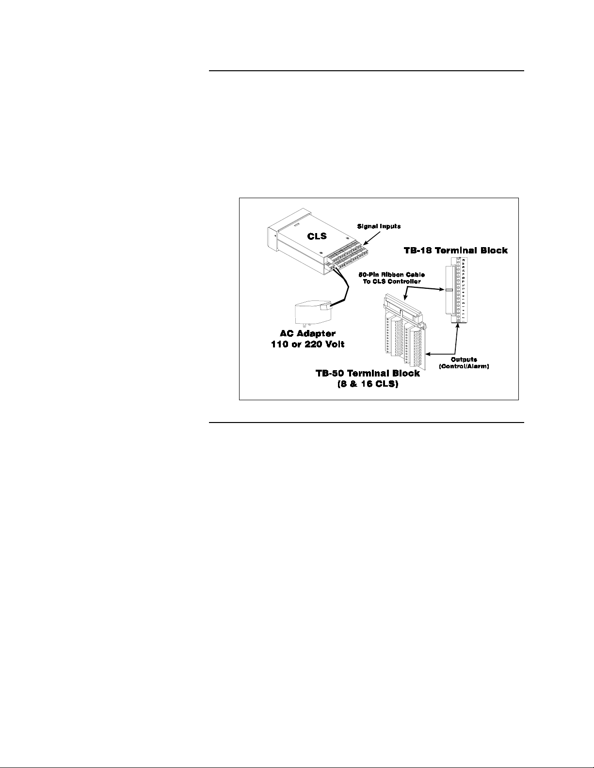
System Diagram
The illustration below shows how the parts of the CLS are connected.
When unpacking your system, use the diagrams and parts list below to
ensure all parts have been shipped. Please don't hesitate to call Watlow
Anafaze's Technical Service Department if you have problems with
your shipment, or if the CLS components are missing or damaged.
.
Parts List
•
CLS controller
•
Controller mount kit
•
AC adapter (110V or 220V)
•
Terminal Block (TB-50 or TB-18)
•
TB-50 or TB-18 mounting kit
•
50 pin flat ribbon cable (50 pin ribbon cable)
•
DAC or SDAC (optional)
•
User Manual
2 CLS User’s Guide
Page 11

Safety
Overview
Watlow Anafaze has made efforts to ensure the reliability and safety of
the CLS Controller and to recommend safe usage practices in systems
applications. Please note that, in any application, failures can occur.
These failures may result in full control outputs or other outputs which
may cause damage to or unsafe conditions in the equipment or process
connected to the CLS Controller.
Good engineering practices, electrical codes, and insurance regulations
require that you use independent external safety devices to prevent
potentially dangerous or unsafe conditions. Assume that the Watlow
Anafaze CLS Controller can fail with outputs full on, outputs full off, or
that other unexpected conditions can occur.
Install high or low temperature protection in systems where an
overtemperature or undertemperature fault condition could present a fire
hazard or other hazard. Failure to install temperature control protection
where a potential hazard exists could result in damage to equipment and
property, and injury to personnel.
The CLS includes a reset circuit that sets the control outputs off or to the
data stored in memory if the microprocessor resets--normally the result
of a power failure and power return. If a memory-based restart will be
unsafe for your process, program the CLS Controller to restart with
outputs off. For additional safety, program the computer or other host
device to automatically reload the desired operating constants or process
values on return of operating power. However, these safety features do
not eliminate the need for external, independent safety devices in
potentially dangerous or unsafe conditions.
Watlow Anafaze also offers ANASOFT
®
program for IBM-AT
event of a reset, ANASOFT will reload the CLS Controller with the
current values in computer memory. The user must ensure that this reset
will be safe for the process. Again, use of ANASOFT does not eliminate
the need for appropriate external, independent safety devices.
Contact Watlow Anafaze immediately if you have any questions about
system safety or system operation.
or IBM-PC® compatible computers. In the
®
, an optional software
CLS User’s Guide 3
Page 12

Overview
4 CLS User’s Guide
Page 13

Introduction
The CLS is a modular control system with up to 16 fully independent
loops of PID control (16 CLS). It functions as a stand-alone controller;
the CLS 1/8 DIN front panel has a Liquid Crystal Display (LCD) and
touch keypad for local display and local parameter entry. You can also
use it as the key element in a computer-supervised data acquisition and
control system; the CLS can be locally or remotely controlled via an
RS-232 or RS-485 serial communications interface.
The CLS features include:
Direct Connection of Mixed Thermocouple Sensors: Directly
connect most thermocouples with the CLS versatile hardware.
Thermocouple inputs feature reference junction compensation,
linearization, PV offset calibration to correct for sensor inaccuracies, T/
C upscale break detection, and a choice of Fahrenheit or Celsius display.
Introduction
Resistive Temperature Detector Sensors are Standard Inputs: Two
types of standard three wire 100 ohm platinum DIN curve sensor are
standard inputs for the CLS. (To use this input, order the CLS with
scaling resistors.)
Automatic Scaling for Linear Analog Inputs: The CLS automatically
scales linear inputs used with other industrial process sensors. Simply
enter two measurement points. For example, to scale a PSI sensor enter
the endpoints: Low PV is 10 PSI, while High PV is 100 PSI. All other
values for that loop will automatically be in PSI.
Dual Outputs Standard: The CLS includes dual control outputs for
each loop, with independent control constants for each output.
Independently Selectable PID Output Modes: You can set each
control output to ON/OFF, Time Proportioning, Serial DAC, or
Distributed Zero Crossing mode. You can set each output control mode
for ON/OFF, P, PI, or PID control with reverse or direct action.
Flexible Alarm Outputs: Independently set high/low process alarms
and a high/low deviation band alarm for each loop. Alarms can activate
a digital output by themselves, or they can be grouped with other alarms
to activate an output.
Alarm or Control Outputs: You can set high/low deviation and high/
low process setpoints to operate digital outputs as on/off control
functions instead of alarms. (The control function has no alarm
notification or global alarm output.)
Global Alarm Output: When any alarm is triggered, the Global Alarm
Output is also triggered, and it stays on until you acknowledge it.
CLS User’s Guide 5
Page 14

Introduction
Watchdog Timer: The CLS watchdog timer output notifies you of
system failure. You can use it to hold a relay closed while the controller
is running, so you are notified if the microprocessor shuts down.
Front Panel or Computer Operation: Set up and run the CLS from
the front panel or from a local or remote computer. Watlow Anafaze
offers ANASOFT, our IBM AT or IBM-PC compatible software you can
use to operate the CLS. ANASOFT has these features:
•
Process Overviews
•
Parameter Setup
•
Graphic Trend Plotting
•
Data Logging
Multiple Job Storage: Store up to 8 jobs in protected memory, and
access them locally by entering a single job number or remotely via
digital inputs. Each job is a set of operating conditions, including
setpoints and alarms.
Non-Linear Output Curves Standard: Select either of two non-linear
output curves for each control output.
Autotuning Makes Setup Simple: Use the Autotune feature to set up
your system quickly and easily. The CLS internal expert system table
finds the correct PID parameters for your process.
Pulse Counter Input Standard: Use the pulse counter input for precise
control of motor or belt speed.
6 CLS User’s Guide
Page 15

Specifications
Analog Inputs
Introduction
The following section contains specifications for inputs, outputs, the
serial interface, system power requirements, environmental
specifications, and the CLS physical dimensions.
Number of Control Loops:
pulse loop.
Number of Analog Inputs:
Input Switching:
Input Sampling Rate:
4CLS: 6x/sec (167 ms) at 60 Hz; 5x/sec (200 ms) at 50 Hz.
8CLS: 3x/sec (333 ms) at 60 Hz; 2.5x/sec (400 ms) at 50 Hz.
16CLS:1.5x/sec (667 ms) at 60 Hz; 1.25x/sec (300 ms) at 50 Hz.
Analog Over Voltage Protection:
Common Mode Rejection (CMR):
>60 dB DC to 1 kHz, and 120 dB at selected line frequency.
A/D Converter:
Input Range:
resistors.
Resolution:
measurement resolution, not the display resolution.)
differential solid state MUX switching.
Integrates voltage to frequency.
-10 to +60 mV. Other ranges are available with scaling
0.006%, greater than 14 bits. (This is the internal
4 (4CLS), 8 (8CLS), 16 (16CLS), plus one
4 (4CLS), 8 (8CLS), 16 (16CLS).
+
20 V referenced to digital ground.
For inputs that don't exceed +
5 V,
Calibration:
Automatic zero and full scale.
CLS User’s Guide 7
Page 16
Introduction
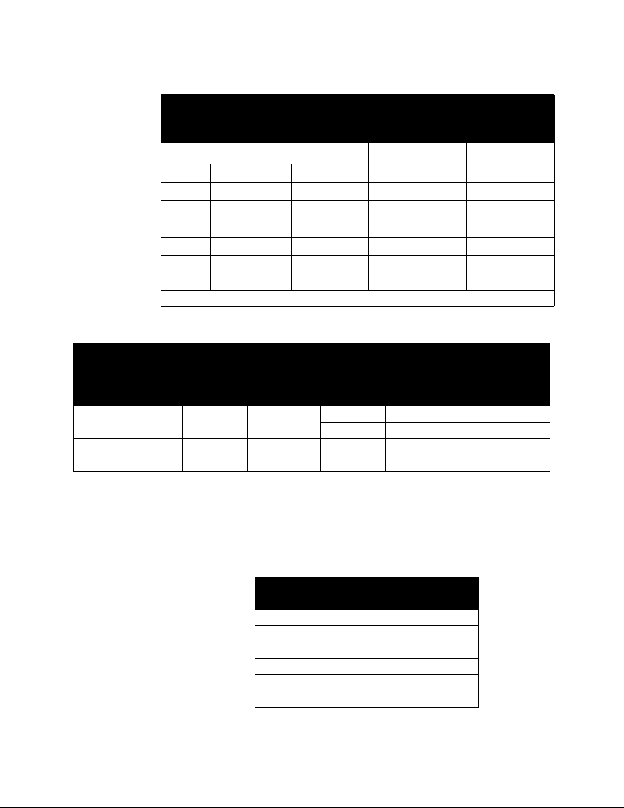
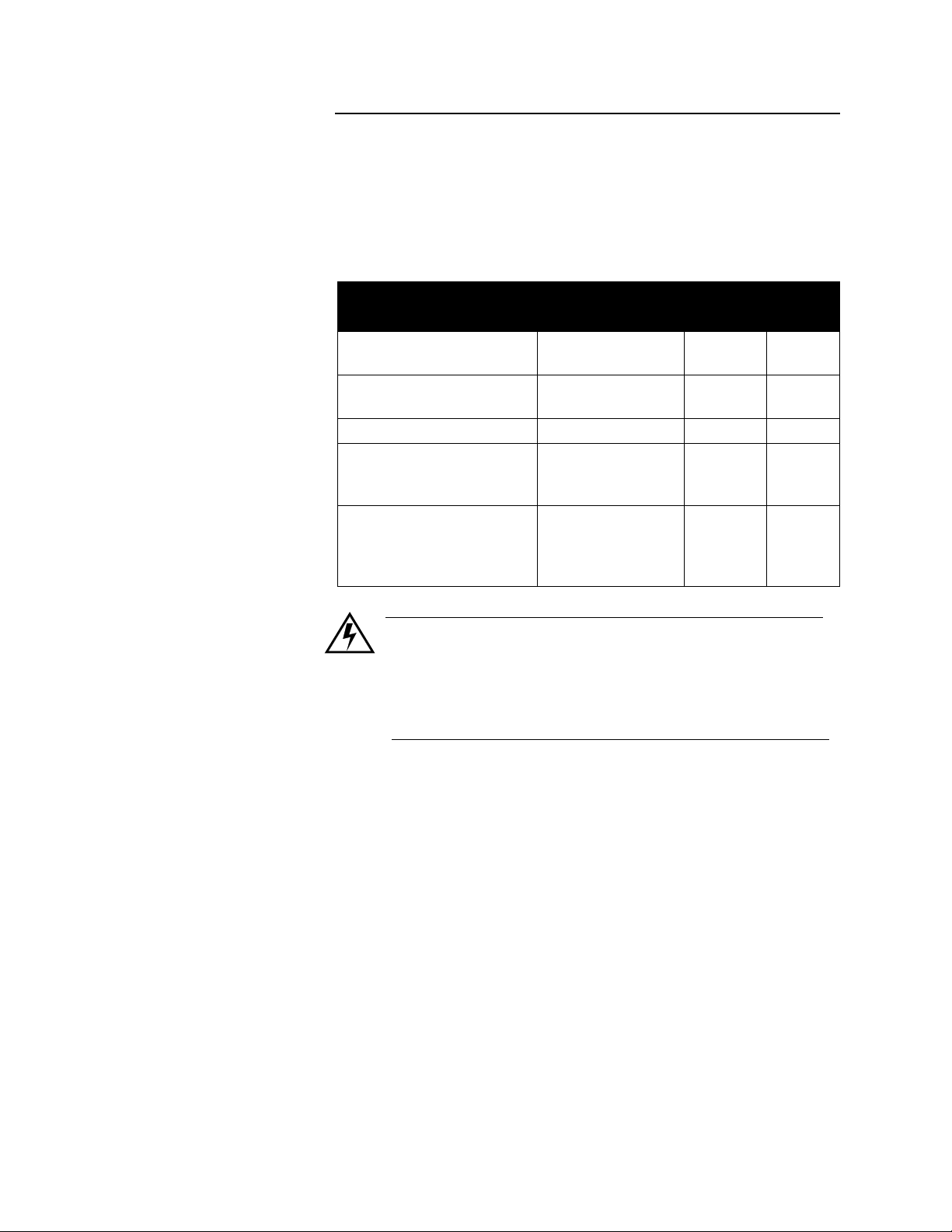
Thermocouple Ranges and Resolution:
Name
RTD1 -148.0 to
RTD2 -184 to
Range in
F
°
527.0
1544
T/C
Type
J T/C -350 to 1400 -212 to 760
K T/C -450 to 2500 -268 to 1371
T T/C -450 to 750 -268 to 399
S T/C 0 to 3200 -18 to 1760
R T/C 0 to 3210 -18 to 1766
B T/C 150 to 3200 66 to 1760
E T/C -328 to 1448 -200 to 787
Range in °F Range in °C
C
°
* True for 10% to 100% of span.
RTD Ranges and Resolution (4 and 8 CLS only)
Range in
C
°
Resolution
Measure-
ment
Temp. In
°
-100.0 to
275.0
-120 to 840
0.023
0.062
°
C
275 ±1 ±1.8 ±1.5 ±2.7
°
C
840 ±1.1 ±1.98 ±4.3 ±7.74
* Accuracy:
C
25
°
Ambient
°
C
±
0.5
±
0.6
±
1.3
±
2.5
±
2.5
±
6.6
±
±
±
±
±
±
°
F
0.9
1.2
2.4
4.5
4.5
12.0
* Accuracy:
C Full
0-50
°
Temp. Range
±
±
±
±
±
±
°
C
1.1
1.35
2.9
5.6
5.6
14.9
±
±
±
±
±
±
°
10.1
10.1
27.0
2.0
2.7
5.4
:
Accuracy:
C
25
°
Ambient
C
25 ±0.35 ±0.63 ±0.5 ±0.9
25 ±0.9 ±1.62 ±2.8 ±5.04
C °F
°
Accuracy:
C
0-50
°
Ambient
C °F
°
F
8 CLS User’s Guide
T/C Break Detection: Pulse type for upscale break detection.
Milliamp inputs: 0-20 mA (3 ohms resistance) or 0-10 mA (6 ohms
resistance), with scaling resistors.
Voltage inputs: 0-12V, 0-10V, 0-5V, 0-1V, 0-500mV, 0-100 mV with
scaling resistors.
Range
0-12 V 85 Kohms
0-10 V 50 Kohms
0-5 V 40 Kohms
0-1 V 7.4 Kohms
0-500 mV 6.2 Kohms
0-100 mV 1.2 Kohms
Source Impedance: For 60 mV T/C, measurements are within
specification with up to 500 ohms source resistance.
Input
Resistance
Page 17

Digital Inputs
Introduction
Number:
Configuration:
Input Voltage Protection:
limit to 10 mA for override conditions.
Voltage Levels:
Maximum Switch Resistance to Pull Input Low:
Minimum Switch Off Resistance:
User-Selectable Digital Outputs
Number:
Operation:
Current
Function:
Number of PID Control Outputs per PID Loop:
PID Control Output Types:
Crossing, SDAC, or On/Off
output. Heat and cool control outputs can be individually disabled for
use as alarm outputs.
8
8 selectable for output override, remote job selection.
Diodes to supply and common. Source must
<1.3V=Low; >3.7V=High (TTL).
1 Kohms.
11 Kohms.
34
Open collector output; On state sinks to logic common.
≤
20 mA for 35 loads. Single load ≤ 40 mA. I total ≤ 700 mA.
Selectable as PID control or alarm/control.
2 (max)
Time Proportioning, Distributed Zero
—
all independently selectable for each
System Digital Outputs
Time Proportioning Cycle Time:
each output.
PID Control Action:
selectable for each output.
Off State Leakage Current:
System Digital Outputs:
Operation:
Current
Open collector output; On state sinks to logic common.
≤
20 mA for 35 loads. Single load ≤ 40 mA. I total ≤ 700 mA.
Reverse (heat) or direct (cool), independently
<.01 mA to DC common.
1 Global Alarm, 1 CPU watchdog.
1-255 seconds, programmable for
CLS User’s Guide 9
Page 18

Introduction
Analog Outputs
The Watlow Anafaze Digital to Analog Converter (DAC) is an optional
module for the CLS. It lets you convert a Distributed Zero Crossing
control output signal to an analog process control signal. You can
purchase a 4-20 mAdc, 0-5 Vdc, and 0-10 Vdc versions of the DAC.
Watlow Anafaze also offers the Serial DAC for precision open-loop
control. 0-5 Vdc/4-20 mAdc jumper selectable.
Contact Watlow Anafaze for more information about the DAC and
Serial DAC.
10 CLS User’s Guide
Page 19

Miscellaneous Specifications
Serial Interface
Type :
Introduction
RS-232 3 wire or RS-485 4 wire.
Isolation:
RS-232 None
RS-485 To EIA RS-485 Specification.
Baud Rate:
Error Check:
Number of Controllers:
32 with RS-485 communications.
Protocol:
Bradley PLC, full duplex.
2400 or 9600, user selectable.
BCC or CRC, user selectable.
1 with RS-232 communications;
Form of ANSI X3.28-1976 (D1, F1), compatible with Allen
System Power Requirements
Vo lt age:
Input Current (no load):
Maximum Current Requirement:
externally loaded, add 1 mA supply current for every 1 mA of load up to
a maximum load of 100 mA. If using the +5V logic supply to power
digital outputs, add 0.6 mA supply current for every 1 mA of load up to
a maximum load of 350 mA. Therefore, the maximum current
requirement is 300 +100 + (0.6 x 350) = 610 mA.)
12-24 Vdc
300 mA max
610 mA. (If the reference voltage is
Physical Dimensions
Environmental Specifications
0 to 50
°
C
°
C
Storage Temperature:
Operating Temperature:
Humidity:
CLS:
mm.)
TB-18:
TB-50:
10 to 95% non-condensing.
1.75 lbs., 1.98
" x
1.025
"
3.2
x 3.4" (8.03 cm x 8.53 cm)
-20 to 60
"
x 3.78" x 7.10" (.8 kg, 50 mm x 96 mm x 180
3.700" (2.57 cm x 9.29 cm)
CLS User’s Guide 11
Page 20

Introduction
12 CLS User’s Guide
Page 21
Installation
Installation
These installation instructions are written for non-technical users; if you
are an electrician or you are technically proficient, they may seem
simple to you. Please at least skim all of the instructions, to make sure
you don't miss anything vital.
This section explains installation for the CLS only. If you are installing
another Watlow Anafaze product (such as an SDAC), see the manual
shipped with it to learn how to install it.
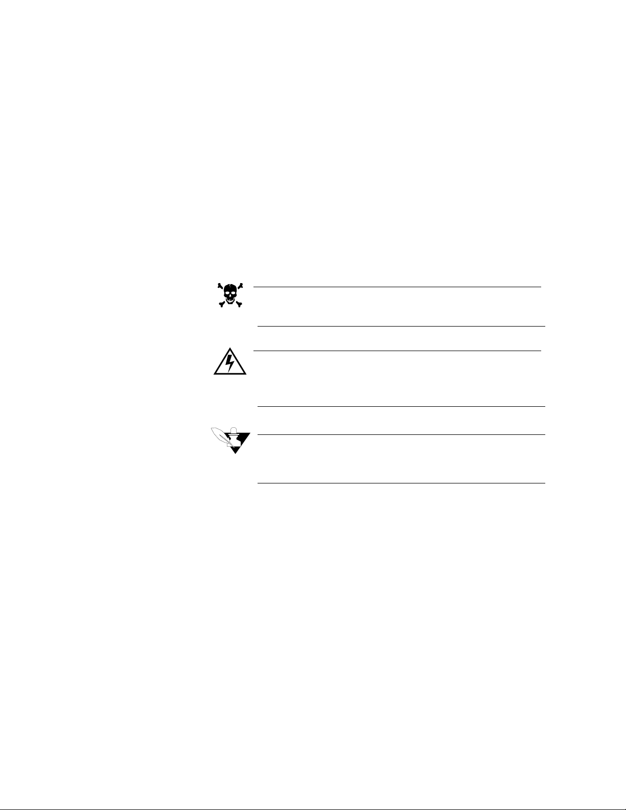
These symbols are used throughout the rest of this manual:
DANGER
This symbol warns you about hazards to human life.
WARNING
This symbol warns you of possible damage to property or
equipment.
NOTE
This symbol denotes information you must know in order
to proceed.
CLS User’s Guide 13
Page 22
Installation
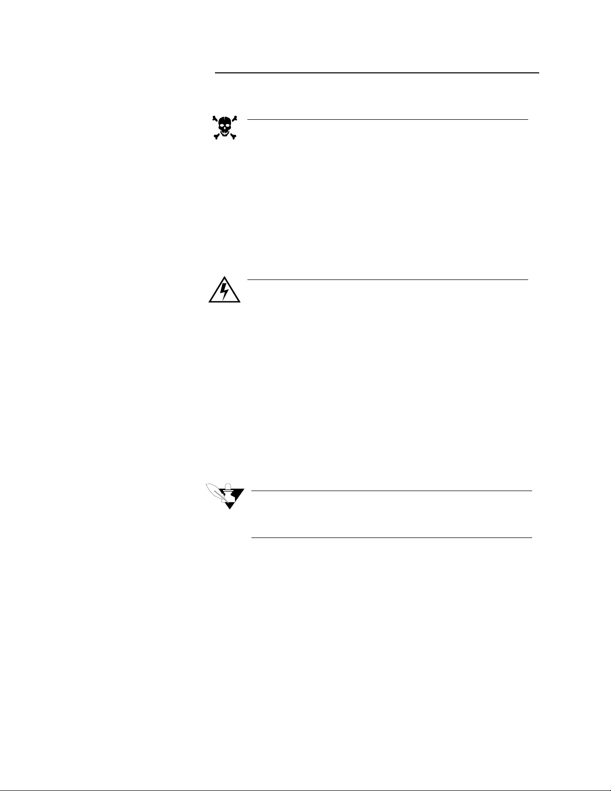
Precautions and Warnings
DANGER
Shut off power to your process before you install the CLS.
High voltage may be present even when power is turned
off! Reduce the danger of electric shock after installation
by mounting the CLS in an enclosure that prevents personal contact with electrical components.
The CLS measures input signals that are not normally referenced to ground, so the CLS inputs and other signal lines
can have high voltage present even when power is turned
off--for example, if you inadvertently short a thermocouple
to the AC power line.
WARNING
During installation and wiring, place temporary covers
over the housing slots and the rear of the CLS so dirt,
pieces of wire, et cetera don't fall through the slots. Remove
these covers after installation.
Install the CLS so the slots in the housing receive unrestricted airflow after installation. Make sure that other
equipment does not block airflow to the housing slots.
Use #20 or #22 AWG wires and trim wire insulation to 1/4”
(5 mm). Wire should fit inside the terminal with no bare
wire exposed, to prevent contact between wires and the
grounded case. Tin any stranded wire.
Support power, input and output cables to reduce strain on
the terminals and to prevent wire removal.
14 CLS User’s Guide
NOTE
Be sure to select a panel location that leaves enough clearance to install and remove the CLS and its components.
Page 23

Recommended Tools
Panel Hole Cutters
Other Tools
Installation
Use these tools to install the CLS:
Use any of the following tools to cut a hole of the appropriate size in the
panel.
•
Jigsaw and metal file--for stainless steel and heavyweight panel
doors.
•
Greenlee 1/8 DIN rectangular punch (Greenlee part # 600-68), for
most panel materials and thicknesses.
•
Nibbler and metal file--for aluminum and lightweight panel doors.
You will also need these tools:
•
Phillips head screwdriver.
•
Flathead screwdriver for wiring.
•
Multimeter.
CLS User’s Guide 15
Page 24
Installation
CLS Mounting Procedure
Mounting Environment
NOTE
Mount the controller before you mount the terminal block
or do any wiring. The controller's placement affects placement and wiring considerations for the other components
of your system.
Install the CLS in a location free from excessive (>50ºC) heat, dust, and
unauthorized handling. The controller can mount in any panel material
up to 0.2" thick. (Make sure there is enough clearance for mounting
brackets and terminal blocks; the controller extends 6.2" behind the
panel face and the screw brackets extend 0.5" above and below it.)
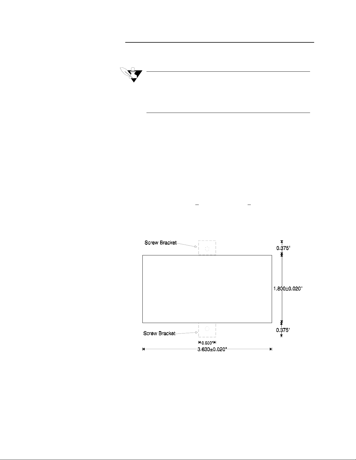
Steps:
1. Cut a hole 3.630+0.020" long by 1.800+0.020" tall in the panel.
This figure shows the mounting hole. (The figure is not a template.)
Cut carefully; the 0.020" (0.5 mm) tolerances don't allow much
room for error. Use a punch, nibbler, or jigsaw, and file the edges of
the hole.
16 CLS User’s Guide
2. Insert the controller into the hole through the front of the panel.
3. Screw the top and bottom clips in place: insert the screw's lip into
the cutout in the metal housing just behind the front panel. Tighten
the screw.
4. If you expect much panel vibration, use a rear support for the CLS
and its interconnecting cables.
Page 25
TB-18 Mounting Instructions
These steps describe how to mount the TB-18 on the rear of the CLS.
(Please follow these steps exactly, so you do not damage either the
terminal block or the controller.)
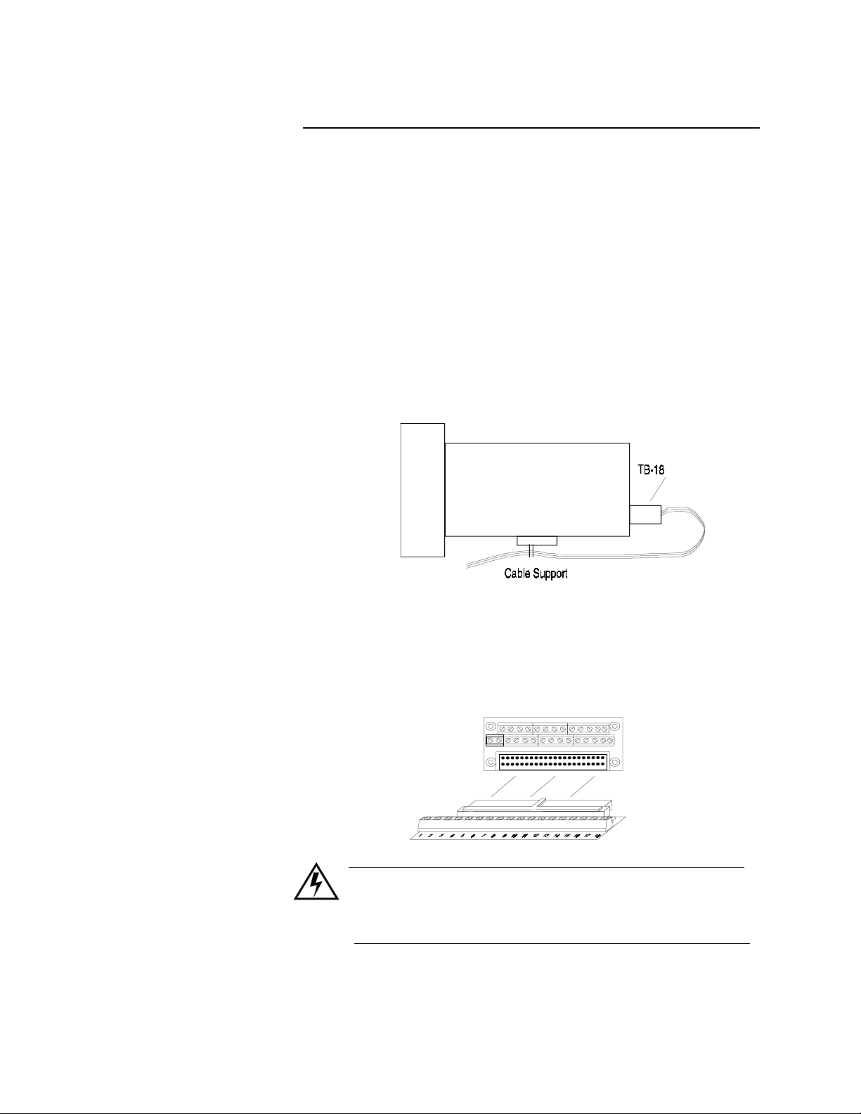
1. Install the cable support on the underside of the CLS. The TB-18
was shipped to you in a plastic bag. The bag also contained a cable
tie (the long plastic strip) and a cable tie mount (the square plastic
piece with one sticky side).
a. Stick the cable tie mount to the underside of the CLS. Install it
b. Thread the cable tie through the hole in the cable tie mount.
Installation
in a spot that won't block the vents.
When you're finished wiring the outputs, it should look like
this illustration.
2. Next, wire outputs to the terminal block. (For help, see Wiring Outputs later in this chapter.) Route wires through the cable support,
leaving about 9" of wire between the TB-18 and the support.
3. Gently slide the female part of the terminal block into the 50-pin
header on the rear of the controller, as shown here.
WARNING
Do not connect power to the CLS now. Test the unit first, as
explained in the Power Wiring and Controller Test section.
CLS User’s Guide 17
Page 26
Installation
1
TB-50 Mounting Instructions
These steps tell you how to mount the TB-50. (Please follow these steps
exactly, so you don’t damage the terminal block, the ribbon cable, or the
controller.)
1. Choose a mounting location. Be sure there is enough clearance to
install and remove the TB-50; it measures 3.4" long X 3.2" wide X
1.27" tall.
2. Watlow Anafaze shipped the TB-50 to you in an antistatic bag.
Make sure these parts are also in the bag:
•
Five plastic standoffs.
•
Five 6-32 screws.
•
Five cable tie wraps.
•
One 50-pin ribbon cable.
•
Five ribbon cable clamps.
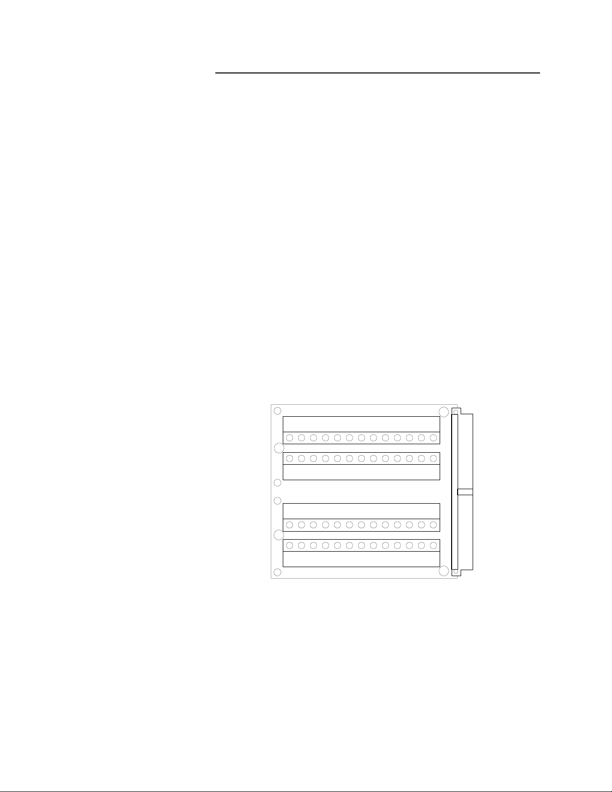
3. Snap four of the plastic standoffs into the four mounting holes on
the TB-50.
There are also four smaller holes on the terminal board, as shown
here. These holes are for the cable tie wraps--the plastic standoffs
won’t fit them. You’ll use these holes to secure wiring to the terminal block. (See
Wiring Outputs
in this chapter for help installing
cable tie wraps.)
A
B
3938B
4443424140
504948474645
A
36
B
B
A
B
Holes labeled "A"are m ounting holes.
Holes labeled "B"aretiewrap holes.
35
3738A
34
3233
29
3031
262728
25242322212019181716151413B
12345678910111213A
A
18 CLS User’s Guide
Page 27
Installation
4. Place the TB-50 where you will mount it and use a pencil to trace
around the standoffs.
5. Drill and tap #6-32 holes in the locations you marked.
6. Place the TB-50 where you will mount it. Insert the #6 screws in the
standoffs and tighten them.
NOTE
Save the cable tie wraps, ribbon cable, and ribbon cable
clamps. You’ll use them when you wire outputs to the TB50 and when you connect the ribbon cable.
WARNING
Do not connect power to the CLS now. Test the unit first, as
explained in the Power Wiring and Controller Test section.
CLS User’s Guide 19
Page 28
Installation
General Wiring Recommendations
Use the cables below or their equivalent. For best results, use
appropriate materials, proper installation techniques and the correct
equipment. For example, choose wire type by function, installation
requirements, and the likelihood of mechanical or electrical problems
at your installation.
Function MFR P/N
Analog inputs Belden #9154
Belden #8451
RTD Inputs (4 & 8 CLS) Belden #8772
Belden #9770
T/C Inputs T/C Ext. Wire 2 20
Digital PID outputs and Dig-
ital I/O
Computer Communication:
RS232 or RS485
Belden #9539
Belden #9542
Ribbon Cable
Belden #9729
Belden #9730
Belden #9842
Belden #9843
No. of
Wires
2
2
3
3
9
20
50
4
6
4
6
20
22
20
22
24
24
24
24
24
24
WARNING
Never wire bundles of low power controller circuits next to
bundles of high power AC wiring. Instead, physically separate high power circuits from the controller. If possible,
install high voltage AC power circuits in a separate panel.
AWG
20 CLS User’s Guide
•
Use stranded wire. Solid wire is used for fixed service; it makes
intermittent connections when you move it for maintenance.
•
Use #20 or #22 AWG wire. Larger or smaller sizes may be difficult
to install, may break easily, or may cause intermittent connections.
•
Use shielded wire. (The electrical shield helps protect the CLS from
electrical noise.) Connect one end of the input wiring shield to the
CLS panel's 120 Vac panel ground, and connect one end of the output wiring shield to the CLS panel's 120 Vac panel ground. (Some
installations may require a different shield configuration. Contact
Watlow Anafaze for more information if these instructions do not
apply to your system.)
For more noise suppression measures, see
Noise Suppression
.
Page 29

Grounding
Installation
Connect the CLS chassis to an external ground at only one point, to
avoid ground loops that can cause instrument errors or malfunctions.
Since the CLS uses a non-isolated measurement system, it has the
following connections to power supply common:
•
Analog common TB1 pins 5, 6, 11, & 12
•
Reference common, TB1 pin 17
•
Communications ground (TB1 pins 23 & 24) if using RS-232
•
Power supply ground, TB2 pin 2
•
Control common (TB-18 pin 2; TB-50 pin 3 and 4)
Watlow Anafaze strongly recommends that you:
•
Do not connect any one of these pins to earth ground. Do not tie
them together externally.
•
Isolate outputs through solid state relays, where possible.
•
Isolate RTDs or “bridge” type inputs from ground, if used.
•
Isolate digital inputs from ground through solid state relays. If you
can't do that, then make sure the digital input is the only place that
one of the above pins connects to ground.
•
If you are using RS-232 from an un-isolated host, don't connect any
other power common point to earth ground.
CLS User’s Guide 21
Page 30
Installation
Thermocouple Wiring
Use 18 or 20 AWG thermocouple (T/C) extension wire for all the T/C
inputs.
NOTE
Most thermocouple wire is solid unshielded wire. Use
shielded wire if required at your installation; ground one
end only.
WARNING
The CLS uses a floating ground system. Therefore:
Isolate input devices or host computers connected through
communications cables (like RS-232) from earth ground.
Use ungrounded thermocouples with the thermocouple
sheath electrically connected to earth ground.
Use optically isolated RS-232 devices to isolate earth
grounded host computers from CLSs.
When you use grounded T/Cs, tie the thermocouple shields
to a common earth ground in one place. Otherwise any
common mode voltages that exceed 5 volts may cause
incorrect readings or damage to the controller.
Input Wiring
WARNING
The 16CLS has single ended inputs, offering little protection from common mode voltage sources. Therefore
Watlow Anafaze highly recommends that you use
ungrounded thermocouples with the external thermocouple sheath electrically connected to earth ground.
You can use 400 to 500' of thermocouple extension wire, depending on
wire type and wire size, and keep to accuracy and source impedance
specifications. Be sure to install thermocouple wiring in a separate
conduit away from AC power (the 120 Vac control supply) and high
power (240 Vac or higher) wiring.
Use multicolored stranded shielded cable for analog inputs. Watlow
Anafaze recommends that you use #20 AWG wire. (If the sensor
manufacturer requires it, you can also use #22 or #24 AWG wiring.)
Most inputs use a shielded twisted pair; some require a 3 wire input.
22 CLS User’s Guide
Page 31

Output Wiring
Communications Wiring
Installation
Use multicolored stranded shielded cable for analog outputs (if you
have installed an SDAC) and PID digital outputs connected to panel
mount SSRs. Analog outputs generally use a twisted pair, while digital
outputs have 9-20 conductors, depending on wiring technique.
For instructions on using the cable tie wraps included in the TB-50’s
packaging, see the
Large systems can pull in an extra pair to the computer communications
wiring. The extra pair services a sound power phone system for
communications between the Watlow Anafaze controller and a
computer.
If you choose this option for maintenance, calibration checking, et
cetera, Watlow Anafaze recommends a David Clark #H5030 system.
Wiring Outputs
section.
CLS User’s Guide 23
Page 32

Installation
Wiring: Noise Suppression
If the CLS's outputs control dry contact electromechanical relays with
inductive loads--like alarm horns and motor starters
Electro-magnetic Interference (EMI, or “noise”) The following section
explains how to avoid noise problems; read it before you wire the CLS.
--
you may get
Symptoms of RFI/EMI
If your controller displays the following symptoms, suspect EMI.
•
The CLS's display blanks out and then reenergizes as if power had
been turned off for a moment.
•
The process value does not display correctly.
EMI may also damage the digital output circuit--so digital outputs will
not energize. If the digital output circuit is damaged, return the
controller to Watlow Anafaze for repair.
Avoiding Noise Problems
To avoid noise problems:
Where possible, use solid state relays (SSRs) instead of
electromechanical (EM) relays. If you must use EM relays, try to avoid
mounting them in the same panel as the CLS equipment.
Separate the 120 Vac power leads from the low level input and output
leads connected to the CLS. Don't run the digital output or PID control
output leads in bundles with 120 Vac wires. (Never run input leads in
bundles with high power leads. See the General Wiring section.)
If you must use EM relays and you must place them in a panel with CLS
equipment, use a .01 microfarad capacitor rated at 1000 Vac (or higher)
in series with a 47 ohm,
relay load. This network is known as an arc suppressor or snubber
network.
You can use other voltage suppression devices, but they are not usually
required. For instance, you can place a metal oxide varistor (MOV)
rated at 130 Vac for 120 Vac control circuits across the load, which
limits the peak AC voltage to about 180 Vac (Watlow Anafaze P/N 26130210-00). You can also place a transorb (back to back zener diodes)
across the digital output, which limits the digital output loop to 5 Vdc.
(All the parts mentioned here are available from Watlow Anafaze).
½
watt resistor across the NO contacts of the
24 CLS User’s Guide
The above steps will eliminate most noise problems. If you have further
problems or questions, please contact Watlow Anafaze.
Page 33

General Wiring
The following sections explain how to test your installation before you
connect power to it and how to connect inputs and outputs to it.
Power Wiring and Controller Test
When you have installed each component of the controller and the TB50 (if used), use this checklist to connect them. These instructions are
written so that non-electricians can understand them. If you are an
experienced electrician, they may seem elementary to you. If so, feel
free to skim them.
Connecting Power and TB-50 to CLS
1. Remove the temporary covers on the CLS housing.
2. The plug-in power supply, included with your controller, has two
bare wires. The + side connects to TB2-1, and the - side to TB2-2.
As a precaution, you should check the polarity of the wires with a
multimeter (color coding of the wires is not always reliable with
older power supplies).
3. Connect the ribbon cable to the controller, as shown here. Plug it in
so the red stripe is on the left side as you face the back of the controller.
Installation
Do not turn on the AC power yet
.
4. Connect the ribbon cable to the TB-50. The cable is keyed, so you
cannot insert it backwards.
WARNING
Do not turn on the AC power yet. Test the connections first,
as explained in the Connections Test section below.
Excessive voltage to the CLS will damage it, and you will
need to return it to Watlow Anafaze for repair. If you use
your own power supply, read the next section completely
and follow its instructions before you apply power to the
CLS.
CLS User’s Guide 25
Page 34

Installation
Connections Test
Again, follow these instructions if you have purchased your own power
supply, or if you are using a Watlow Anafaze power supply, you don’t
need to perform this test.
1. Unscrew the two screws on the sides of the CLS front panel.
2. Gently slide the electronics assembly out of the case. You have now
removed the parts of the CLS which will be damaged by excess
voltage, so plug in the transformer power supply and use a voltmeter to check voltages:
3. Touch the meter Common lead to the back Terminal Block 2 (TB2)
terminal 2 on the CLS. The voltage on TB2 terminal 1 should then
be +12 to 24 Vdc.
4. If the voltages are within the limits described above,
a. Turn off power.
b. Slide the electronics assembly back into the processor mod-
ule’s casing.
c. Reinsert screws into the screw holes on the casing and lighten
them.
d. Turn the power back on. The CLS display should light up, and
after about a second the Bar Graph display should appear.
If you have not connected analog inputs yet, the CLS may display a “T/C Break” alarm message for each channel. This is
normal; to clear the alarm messages, press ALARM ACK
once for each alarm message.
26 CLS User’s Guide
Page 35

Outputs
Installation
NOTE
Your CLS is shipped with heat outputs enabled and cool
outputs disabled. You can disable any PID output and use it
for other digital output functions.
All digital outputs and PID outputs are sink outputs referenced to the
5Vdc supply. These outputs are Low (pulled to common) when they are
On.
All digital inputs are Transistor-Transistor Logic (TTL) level inputs
referenced to control common.
The control outputs are located on the 50 pin header which connects to
the TB-18 or TB-50 pin flat ribbon cable. This section explains how to
wire and configure them.
Wiring Outputs
The CLS provides dual PID control outputs for each loop. The digital
outputs sink current from a load connected to the CLS's internal power
supply or from an external power supply referenced to CLS ground.
•
If you use an external power supply, do not exceed +12 volts.
•
If you tie the external load to ground, or if you cannot connect it as
shown below, then use a solid state relay.
•
If you connect an external supply to earth or equipment ground, use
solid state relays to avoid ground currents. (Ground currents may
degrade analog measurements in the CLS).
The outputs conduct current when they are “True”. The maximum
current sink capability is 20 mA (when all outputs are used). They
cannot “source” current to a ground load
CLS User’s Guide 27
Page 36

Installation
28 CLS User’s Guide
Page 37

Installation
1
Using the Cable Tie Wraps
When you have wired outputs to the TB-50, use the cable tie wraps
shipped with it. This diagram shows the cable tie wrap holes.
A
B
A
50494847464544434241403938B
36
B
B
A
B
3738A
Holes labeled "A"are m ounting holes.
Holes labeled "B"aretiewrap holes.
33
35
34
29
303132
262728
25242322212019181716151413B
12345678910111213A
A
Each row of terminals has a cable tie wrap hole at one end. Thread the
cable tie wrap through the cable tie wrap hole. Then wrap the cable tie
wrap around the wires attached to that terminal block.
Configuring Outputs
•
You can enable or disable the control outputs. The default setting is
heat outputs enabled, cool outputs disabled.
•
You can program each control output individually for On/Off, TP,
SDAC, or DZC control.
•
You can individually program each control output for direct or
reverse action.
CLS User’s Guide 29
Page 38

Installation
PID Control and Alarm Output Connections
Typical digital control outputs use external optically isolated solid-state
relays (SSRs). The SSRs use a 3 to 32 Vdc input for control, and you
can size them to switch up to 100 amps at 480 Vac. For larger currents,
you can use these optically isolated relays to drive contactors. You can
also use Silicon Control Rectifiers (SCRs) and an SDAC for phaseangle fired control.
NOTE
Control outputs are SINK outputs. They are Low when the
output is On. Connect them to the negative side of Solid
State Relays.
The figure below shows sample heat/cool and alarm output connections.
Watchdog Timer
The CLS watchdog timer constantly monitors the CLS microprocessor.
It is a sink output located on TB-18 terminal #3, or on TB-50 terminal
#6. (Do not exceed the 10 mAdc rating for the watchdog timer.) Its
output is Low (on) when the microprocessor is operating; when it stops
operating, the output goes High (off), which de-energizes the SSR.
This figure shows the recommended circuit for the watchdog timer
output.
30 CLS User’s Guide
Page 39

TB-18 Connections
Installation
This table shows TB-18 connections to the 4CLS and the 8CLS.
PIN Function
1+5 Vdc
2 Digital ground
3 Watchdog timer
4Global alarm
5 Digital output 1 Loop 1 heat Loop 1 heat
6 Digital output 2 Loop 2 heat Loop 2 heat
7 Digital output 3 Loop 3 heat Loop 3 heat
8 Digital output 4 Loop 4 heat Loop 4 heat
9 Digital output 5 Pulse loop heat Loop 5 heat
10 Digital output 6 Loop 1 cool Loop 6 heat
11 Digital output 7 Loop 2 cool Loop 7 heat
12 Digital output 8 Loop 3 cool Loop 8 heat
13 Digital output 9 Loop 4 cool Pulse loop heat
14 Digital output 10 Pulse loop cool Loop 1 cool
15 Digital output 34* SDAC clock SDAC clock
16 Digital input 1
17 Digital input 2
18 Digital input 3
/Pulse input
PID Output
4CLS 8CLS
*If you install a Watlow Anafaze Serial DAC (SDAC), the CLS uses
digital output #34 for a clock line. You cannot use output #34 for
anything else when you have an SDAC installed.
CLS User’s Guide 31
Page 40

Installation
TB-50 Connections
4 and 8 CLS TB-50 Connections.
Pin Function
1 +5 Vdc 2 +5 Vdc
3 CTRL COM 4 CTRL COM
5 Not Used 6 Watchdog Timer
7 Pulse Input 8 Global Alarm
9 DIG output 1 Loop 1 heat Loop 1 heat 10 DIG output 34*
11 DIG output 2 Loop 2 heat Loop 2 heat 12 DIG output 33
13 DIG output 3 Loop 3 heat Loop 3 heat 14 DIG output 32
15 DIG output 4 Loop 4 heat Loop 4 heat 16 DIG output 31
17 DIG output 5 Loop 5 heat Pulse loop
19 DIG output 6 Loop 6 heat Loop 1 cool 20 DIG output 29
21 DIG output 7 Loop 7 heat Loop 2 cool 22 DIG output 28
23 DIG output 8 Loop 8 heat Loop 3 cool 24 DIG output 27
25 DIG output 9 Pulse loop
heat
27 DIG output 10 Loop 1 cool Pulse loop
29 DIG output 11 Loop 2 cool 30 DIG output 24
31 DIG output 12 Loop 3 cool 32 DIG output 23
33 DIG output 13 Loop 4 cool 34 DIG output 22
35 DIG output 14 Loop 5 cool 36 DIG output 21
37 DIG output 15 Loop 6 cool 38 DIG output 20
39 DIG output 16 Loop 7 cool 40 DIG output 19
41 DIG output 17 Loop 8 cool 42 DIG output 18 Pulse loop
43 DIG input 1 44 DIG input 2
45 DIG input 3 46 DIG input 4
47 DIG input 5 48 DIG input 6
49 DIG input 7 50 DIG input 8
PID Output*
8CLS 4CLS
heat
Loop 4 cool 26 DIG output 26
cool
Pin Function
18 DIG output 30
28 DIG output 25
PID Output*
8CLS 4CLS
cool
32 CLS User’s Guide
If you install a Watlow Anafaze Serial Digital to Analog Converter
(SDAC), the CLS uses digital output #34 for a clock line. You cannot
use output #34 for anything else when you have an SDAC installed.
* The indicated outputs are dedicated to PID (or control) when enabled
in the loop setup. If one or both of a loop’s outputs are disabled, the
corresponding digital outputs become available for alarms or ramp/soak
events.
Page 41

Installation
16 CLS TB-50 Connections.
Pin Function PID Output* Pin Function PID Output*
1 +5 Vdc 2 +5 Vdc
3 Digital Ground 4 Digital Ground
5 Not Used 6 Watchdog Timer
7 Pulse Input 8 Global Alarm
9 DIG output 1 Loop 1 heat 10 DIG output 34* Pulse loop cool
11 DIG output 2 Loop 2 heat 12 DIG output 33 Loop 16 cool
13 DIG output 3 Loop 3 heat 14 DIG output 32 Loop 15 cool
15 DIG output 4 Loop 4 heat 16 DIG output 31 Loop 14 cool
17 DIG output 5 Loop 5 heat 18 DIG output 30 Loop 13 cool
19 DIG output 6 Loop 6 heat 20 DIG output 29 Loop 12 cool
21 DIG output 7 Loop 7 heat 22 DIG output 28 Loop 11 cool
23 DIG output 8 Loop 8 heat 24 DIG output 27 Loop 10 cool
25 DIG output 9 Loop 9 heat 26 DIG output 26 Loop 9 cool
27 DIG output 10 Loop 10 heat 28 DIG output 25 Loop 8 cool
29 DIG output 11 Loop 11 heat 30 DIG output 24 Loop 7 cool
31 DIG output 12 Loop 12 heat 32 DIG output 23 Loop 6 cool
33 DIG output 13 Loop 13 heat 34 DIG output 22 Loop 5 cool
35 DIG output 14 Loop 14 heat 36 DIG output 21 Loop 4 cool
37 DIG output 15 Loop 15 heat 38 DIG output 20 Loop 3 cool
39 DIG output 16 Loop 16 heat 40 DIG output 19 Loop 2 cool
41 DIG output 17 Pulse loop heat 42 DIG output 18 Loop 1 cool
43 DIG input 1 44 DIG input 2
45 DIG input 3 46 DIG input 4
47 DIG input 5 48 DIG input 6
49 DIG input 7 50 DIG input 8
If you install a Watlow Anafaze Serial digital to Analog Converter
(SDAC), the CLS uses digital output #34 for a clock line. You cannot
use output #34 for anything else when you have an SDAC installed.
* The indicated outputs are dedicated to PID (or control) when enabled
in the loop setup. If one or both of a loop’s outputs are disabled, the
corresponding digital outputs become available for alarms or ramp/soak
events.
CLS User’s Guide 33
Page 42

Installation
Inputs
Input Scaling
This section covers input scaling and input installation for all input
types, including thermocouples, RTDs, current inputs, and voltage
inputs.
The CLS analog input circuitry accepts any mix of thermocouples, 2 or
3 wire RTD inputs, current inputs, and voltage inputs. You can directly
connect the following inputs:
•
J, K, T, S, R, B, and E thermocouples.
•
Linear inputs with ranges between -10 and 60 mV.
Other inputs require custom scaling resistors. If you didn't order your
unit with the appropriate resistors, you have the following options:
•
Watlow Anafaze can install scaling resistors on your unit for a nomi-
nal fee.
•
Watlow Anafaze can supply a scaling resistor kit that a qualified
technician can use to install scaling resistors.
WARNING
A qualified technician can install scaling resistors in the
CLS. However, damage to the CLS due to improper resistor installation is not covered under warranty, and repairs
can be expensive. If you have any doubts about your ability
to install scaling resistors, send your CLS to Watlow
Anafaze for resistor installation.
34 CLS User’s Guide
Page 43

4 and 8 CLS Scaling Values
Installation
•
For RTD1 inputs, RA and RB are a matched pair (RP). Their match-
º
ing tolerance is 0.02% (2 ppm/
0.1% (10 ppm/
•
For RTD2 inputs, use 0.05% tolerance resistors.
•
For linear mVdc, Vdc, and mAdc ranges, use 0.1% tolerance resis-
º
C). RC has 0.05% tolerance.
C) and their absolute tolerance is
tors. Higher tolerances may cause significant errors. Correct any
errors due to resistor tolerance with the CLS's built-in linear scaling.
You can also install other components (like capacitors) for signal
conditioning; please consult Watlow Anafaze for more information.
To
CLS
Circuitry
RD
C .47 uF
A +
( Voltage/Current)
Internal
+5 Vdc
Reference
(RTD/Thermister)
A -
A COM
Analog
Input
Ter min al
RC
RA
RB
RC
C .47 uF
NOTE
When adding your own scaling resisters to the 4 and 8 CLS,
the shorting pads of the RC must be cut before installing to
the bottom of the PC board.
IN +
IN -
CLS User’s Guide 35
Page 44

Installation
The next table shows scaling resistor values.
Input Range RA RB RC RD
All T/C, 0-60 mV DC Jumper
RTD 1: -100.0 to
º
C
275.0
RTD 2: -120 to 840
0-10 mA DC
0-20 mA DC
0-100 mV
0-500 mV
0-1 VDC
0-5 VDC
0-10 VDC
0-12 VDC
º
C
10.0 Kohms
25.0 Kohms
10.0 Kohms
25.0 Kohms
80 ohms
100 ohms
Jumper
Jumper
499 ohms
5.49 Kohms
6.91 Kohms
39.2 Kohms
49.9 Kohms
84.5 Kohms
6.0 ohms
3.0 ohms
750 ohms
750 ohms
422.0 ohms
475.0 ohms
301.0 ohms
422.0 ohms
The following tables show the location of RA, RB, RC and RD on the
analog input boards of the 4CLS and the 8CLS. (The analog input board
is the upper board of the two-board set.)
36 CLS User’s Guide
Page 45

Installation
4CLS: Voltage/Current Inputs
Loop # RC RD
158 RP1
256 RP2
354 RP3
452 RP4
8CLS: Voltage/Current Inputs
Loop RC RD Loop RC RD
158RP1 550RP5
256RP2 648RP6
354RP3 746RP7
452RP4 844RP8
4CLS: RTD/Thermister Inputs
Loop # RA/RB RC
1RP157
2RP255
3RP353
4RP451
8CLS: RTD/Thermister Inputs
Loop RA/RB RC Loop RA/RB RC
1RP157 5RP549
2RP255 6RP647
3RP353 7RP745
4RP451 8RP843
Place resistors RA, RB and RD in the resistor pair locations this way:
A wire trace on the printed circuit board jumpers the RC position. When
you place a resistor in the RC position, cut the wire trace that connects
the two resistor terminals.
CLS User’s Guide 37
Page 46

Installation
16 CLS Scaling Values
For linear mVdc, Vdc, and mAdc ranges, use 0.1% tolerance resistors.
Higher tolerances may cause significant errors. Correct any errors due
to resistor tolerance with the CLS’ built-in linear scaling. You can also
install other components (like capacitors) for signal conditioning; please
consult Watlow Anafaze for more information.
Analog
Input
Term in als
IN +
Analog
Common
RC
RD
CLS Measurement
Circuitry
IN +
The next table shows scaling resistor values.
Input Range RC RD
All T/C, 0-60 mV DC Jumper
0-10 mA DC
0-20 mA DC
0-100 mV
0-500 mV
0-1 VDC
0-5 VDC
0-10 VDC
0-12 VDC
Jumper
Jumper
499 ohms
5.49 Kohms
6.91 Kohms
39.2 Kohms
49.9 Kohms
84.5 Kohms
6.0 ohms
3.0 ohms
750 ohms
750 ohms
422.0 ohms
475.0 ohms
301.0 ohms
422.0 ohms
The next table shows the location of RC and RD on the analog input
board. (The analog input board is the upper board of the two-board set.)
Loop # RC RD Loop # RC RD
1 R58 R42 9 R57 R41
2 R56 R40 10 R55 R39
3 R54 R38 11 R53 R37
4 R52 R36 12 R51 R35
5 R50 R34 13 R49 R33
6 R48 R32 14 R47 R31
7 R46 R30 15 R45 R29
8 R44 R28 16 R43 R27
38 CLS User’s Guide
A wire trace on the printed circuit board jumpers the RC position. When
you place a resistor in the RC position, cut the wire trace that connects
the two resistor terminals.
Page 47

Scaling and Calibration
Installation
The CLS provides offset calibration for thermocouple, RTD, and other
fixed ranges, and offset and span (gain) calibration for linear and pulse
inputs. (Offset and span calibration convert linear analog inputs into
engineering units using the Mx+B function.)
In order to scale linear input signals, you must:
1. Install appropriate scaling resistors. (Contact Watlow Anafaze's
Customer Service Department for more information about installing scaling resistors.)
2. Select the display format. The smallest possible range is
-.9999 to +3.0000; the largest possible range is -9999 to 30000.
3. Enter the appropriate scaling values for your process.
For more information about input scaling and input offset, see
Loop Inputs
Chapter 4: Setup
in
.
Setup
T/C Inputs
WARNING
The CLS uses a floating ground system. Therefore:
Isolate input devices or host computers connected through
communications cables (like RS-232) from earth ground.
Use ungrounded thermocouples with the thermocouple
sheath electrically connected to earth ground.
Use optically isolated RS-232 devices to isolate earth
grounded host computers from the CLS.
When you use grounded T/Cs, tie the thermocouple shields
to a common earth ground in one place. Otherwise any
common mode voltages that exceed 5 volts may cause
incorrect readings or damage to the controller.
WARNING
The 16CLS has single ended inputs, offering little protection from common mode voltage sources. Therefore
Watlow Anafaze highly recommend that you use
ungrounded thermocouples with the external thermocouple sheath electrically connected to earth ground.
CLS User’s Guide 39
Page 48

Installation
You can connect J, K, T, S, R, B, and E thermocouples directly to the
CLS. Watlow Anafaze provides standard linearization and cold junction
compensation for these thermocouple types. (Other thermocouple types
require custom linearization; please contact Watlow Anafaze for more
information about them.)
Connecting Thermocouples
Connect the positive T/C lead to the In+ terminal. Connect the negative
T/C lead to the TB1 In- (4 or 8CLS) or analog common 16CLS)(
terminal. A typical thermocouple connection is shown in the figure
below.
•
Use 20 gauge thermocouple extension wire for all thermocouple
inputs.
•
If you use shielded wire, tie it to panel ground or to ground at the
measurement end.
RTD Inputs (4 and 8 CLS only)
Name Temp. Range
in ºF
RTD1 -148.0 to
527.0 ºF
RTD2 -184 to 1544 ºF-120 to 840
Temp.
Range in
º
C
-100.0 to
º
C
275.0
º
C
IN +
–
IN
The standard industrial RTD is an 100-ohm, 3-wire platinum assembly
as shown in the figure below. Watlow Anafaze highly recommends that
you use the 3-wire RTD to prevent reading errors due to cable
resistance.
•
If you order an RTD1 or RTD2 configuration, Watlow Anafaze will
configure your CLS for the standard 3-wire RTD.
•
If you must use a 4-wire RTD, leave the fourth wire unconnected.
Watlow Anafaze offers 2 standard DIN 385 curve RTD input ranges, as
shown here:
RTD Ranges in Degrees
Resolution Measurement
0.023
0.062
White
Red
Case
Frame Ground
Temperature
º
C 25 ºC
275
º
C 25 ºC
840
Shield (if present)
º
C
º
C
Type J T/C
Error @ 25
º
C Ambient
±0.35 ºC ±0.5 ºC
±
1 ºC
±0.9 ºC ±2.8 ºC
±1.1 ºC ±4.3 ºC
Error @ 0-50
º
C Ambient
±1.5 ºC
40 CLS User’s Guide
Page 49

Current Inputs
Voltage Inputs
Installation
Below is a typical RTD.
Back Terminal Block
Connections
In+
In-
Analog
Common
To connect current (milliamp) inputs, install resistors that convert the
milliamp input to a voltage. Watlow Anafaze offers resistors for 0-20
mA and 0-10 mA current inputs.
•
Connect the + side of the voltage input to the In+ terminal.
•
Connect the - side of the input to the In- terminal for the 4 and 8CLS,
or analog common for the 16CLS. The 0voltage input range is -10 to
60 mV.
•
Scale signals larger than 60 mV with scaling resistors that make full
scale input 60 mV. (For more information, see the Input Scaling section.)
The figures below show typical voltage input.
16CLS
Back Terminal Block
Connections
4 and 8 CLS
Back Terminal Block
Connections
In+
Analog
Common
In+
In-
CLS User’s Guide 41
Page 50

Installation
Unused Inputs
Back Terminal Block Connections
Set the input type for unused inputs to “SKIP” to avoid the default T/C
break alarms. (See Input Type in Chapter 4: Setup for information on
setting the input type.)
Wire inputs to the back terminal block as shown below.
4CLS
8CLS
16 CLS
42 CLS User’s Guide
Page 51

Serial Communications
RS-232 Interface
Installation
The CLS is factory-configured for RS-232 communications. However,
the communications are jumper-selectable, so you can switch between
RS-232 and RS-485. (See Configuring Communications below.) You
can also order a communications cable from Watlow Anafaze or make
your own cable.
With RS-232 communications, you can connect the CLS directly to the
serial communications connector on an IBM-PC or compatible
computer. (PC-compatible computers typically use RS-232
communications.) The RS-232 interface is a standard three-wire
interface. See the table below for connection information. (Some
computers reverse transmit (TX) and receive (RX), so check your
computer manual to verify your connections.)
RX Pin 3 RX Pin 2 TX Pin 26 White
TX Pin 2 TX Pin 3 RX Pin 25 Red
GND Pin 7 GND Pin 5 GND Pin 23 Black
RS-485 Interface
DB 25
Connector
You can use either RS-232 or RS-485 communications in these
situations:
•
When you are using local communications (up to 50 feet).
•
When you are using a single CLS.
If you are using RS-232 communications with grounded thermocouples,
use an optical isolator between the controller and the computer.
This table shows RS-232 connections for 25-pin and 9-pin connectors.
DB 9
Connector
•
If you use more than one CLS, you must use RS-485 communica-
tions.
•
If you have connected the CLS to a computer more than 50 feet
away, Watlow Anafaze recommends that you use RS-485 communications.
If you use RS-485 communications, attach an optically isolated RS-232
to RS-485 converter to the computer. You can use an internal converter
card or an external plug-in converter.
CLS Back TB
Watlow Anafaze
Cable
CLS User’s Guide 43
Page 52

Installation
y
y
y
y
The diagram on the next page shows the recommended system hookup.
To avoid ground loops, it uses an optically isolated RS-232 to RS-485
converter at the host computer. The system is powered from the CLS's
power source or from a secure, isolated supply.
Power
Suppl
Host
Computer
Fifth Wire
Opticall
Isolated
Converter
+-
Power
Suppl
Optional
Capacitor
+-
CLS
Power
Suppl
+
CLS
Wire equipment in a single “daisy chain” using twisted shielded pairs
for the RS-485 cables. Don't use “octopus connections” or “spurs”.
-
44 CLS User’s Guide
Page 53

Installation
Use a 200 ohm terminating resistor on the RX line of the last controller
in the system. (If you have only one controller, it is the last controller in
the system.) Use jumper JU1 to select the terminating resistor; place it
in B position for termination and A position for non-termination.
NOTE
Connect the shields to earth ground only at the computer
or other 485 interface. Do not connect the shield to the
controller.
If you connect RS-485 communications and they do not
function properly, or if you have measurement problems
when communications lines are connected, request additional technical information from the Watlow Anafaze
Customer Service Department.
CLS User’s Guide 45
Page 54

Installation
Configuring Communications
Your controller is shipped configured for RS-232. To switch between
RS-232 and RS-485, change the jumpers as shown here.
You'll need tweezers and a Phillips head screwdriver to switch between
RS-232 and RS-485. Follow these steps:
1. Power down the unit.
2. Remove the controller's metal casing. If you haven't removed the
casing before, please don't try to figure it out yourself; see Changing the PROM in the Troubleshooting section for step-by-step
instructions.
3. Find jumpers JU2, JU3, JU4, and JU5 (above).
4. (This part of the explanation assumes that you're changing the communications from RS-232 to RS-485. If you're not, follow the next
two steps but move the jumpers from the B position to the A position.) Use tweezers to carefully grasp the jumpers and gently slide
them off the pins.
5. Use tweezers to gently slide the jumpers onto the B pins. Move
jumpers JU2, JU3, JU4, and JU5 to the B position, as shown above.
6. If you have changed the controller to 485 communications, put the
200 ohm terminating resistor on the RX line of the last controller in
the system. (If you're only using one controller, it's the last controller in the system.) Place jumper JU1 in the B position . All other
controllers in the system should have JU1 in the A position.
7. Put the casing back on. If you haven't removed or reinstalled the
CLS's casing before, see Chapter 7: Troubleshooting for instruc-
tions.
46 CLS User’s Guide
Page 55

Installation
Recommended Wire Gauges
Watlow Anafaze recommends the following maximum distances and
wire gauges:
Distance Wire Gauge
4000 ft. 24 AWG Belden #9729
6000 ft. 22 AWG Belden #9184
You may wish to use a shield, depending on your noise environment and
grounding problems. The above cables are shielded.
Recommended
Cable
Belden #9842
NOTE
These recommendations are conservative, to ensure that
your controller will operate reliably. Expect satisfactory
performance even if you must deviate slightly from a
design specification.
CLS User’s Guide 47
Page 56

Installation
48 CLS User’s Guide
Page 57

Using the CLS
Introduction
This chapter will show you how to use the CLS from the front panel. (If
you are using ANASOFT or AnaWin, please see the related User's
Guide.) The next diagram shows how to reach the operator menus from
Single Loop display. (To change global parameters, loop inputs, control
parameters, outputs, and alarms from the setup menus, you must enter a
special sequence of keys. To learn how, see the next chapter:
Using the CLS
setup
.)
CLS User’s Guide 49
Page 58

Using the CLS
Front Panel
The front panel provides a convenient interface with the controller. You
can program and operate the CLS with the front panel keys shown
below, or you can use ANASOFT, a program designed specifically for
Watlow Anafaze controllers.
Front Panel Keys
Yes /U p
Ye s
Press
•
•
•
to
Select a menu.
Ye s
Answer
Increase a number or choice you're editing.
to
Ye s /N o
questions.
No/Down
Press No to
•
Skip a menu you don't want to edit, when the prompt is blinking.
•
Answer No to
•
Decrease a number or choice when editing.
•
Perform a No Key Reset.
Ye s/ No
prompts.
50 CLS User’s Guide
Page 59
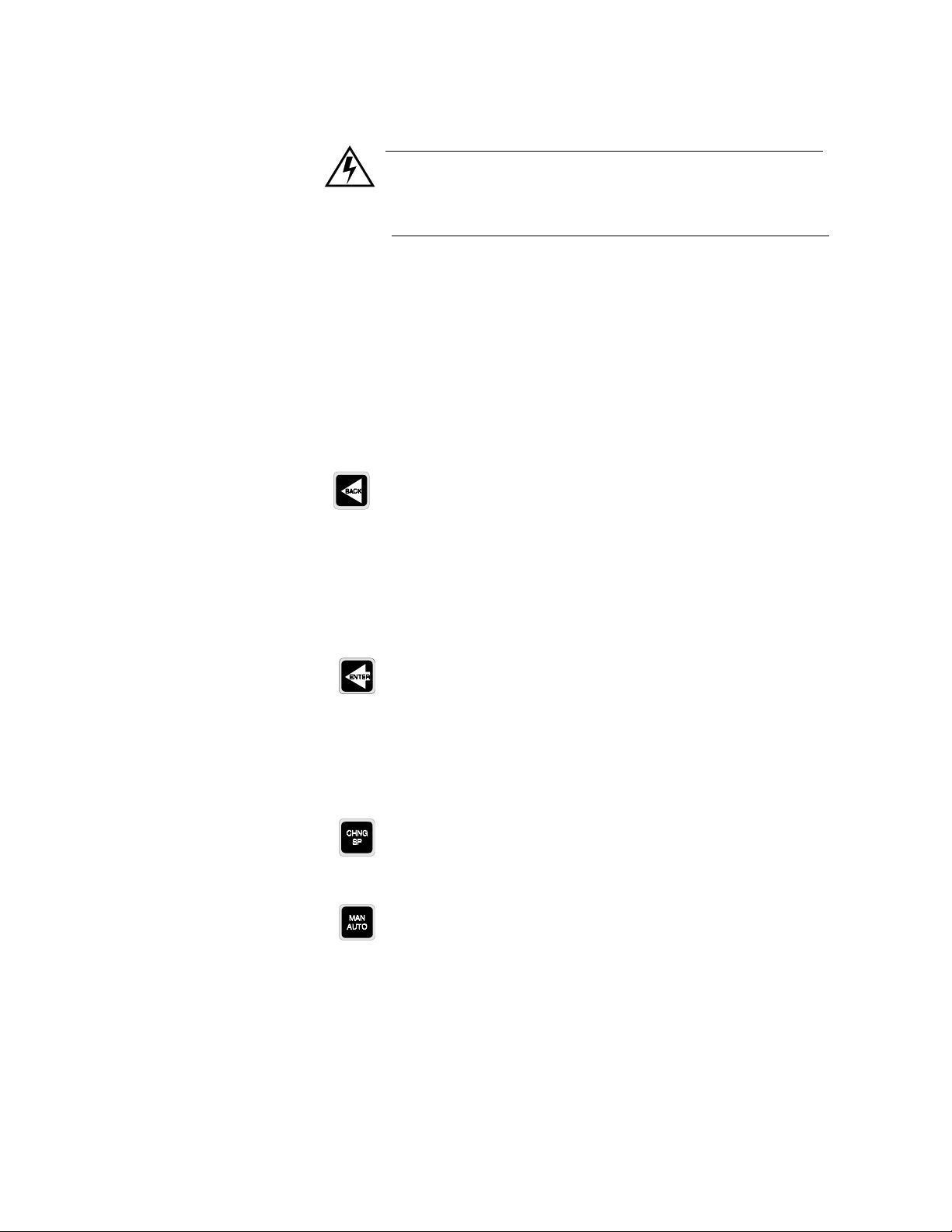
Using the CLS
WARNING
Pressing the No key on power up will clear the RAM memory and reinitialize the CLS' factory default values.
To do a No Key Reset, power down the controller, press and hold the No
key, and power up the controller while holding the No key. A No Key
Reset is appropriate:
•
After you change the EPROM. (See Chapter 6: Troubleshooting.)
•
In some cases when troubleshooting (see Chapter 6: Troubleshoot-
ing).
•
When you install the controller.
Back
Back
The
key works like an “escape key”. Press it to:
•
Abort editing.
•
Return to a previous menu.
•
Switch between Bar Graph, Single Loop, and Job Control displays.
Enter
Enter
Press
•
Store data or menu choices after editing and go on to the next menu.
•
Start scanning mode (if pressed twice).
to:
Change SP
•
Press this key to change the loop setpoint.
Man/Auto
Press the
•
•
•
Man/Auto
Toggle a loop between manual and automatic control.
Adjust the output power level of loops in Manual control.
Automatically tune a loop.
key to:
CLS User’s Guide 51
Page 60

Using the CLS
Ramp/Soak
If Ramp/Soak is installed on your controller, press the Ramp/Soak key
to:
•
Assign a ramp/soak profile to the current loop.
•
Perform operations on an assigned profile.
•
See the status of a running profile.
NOTE
Your CLS may not have the Ramp/Soak feature. If it does not,
then the Ramp/Soak key will not operate. If you press the
Ramp/Soak key, you'll see the following message:
LOOP PROCESS UNITS
OPTION
UNAVAILABLE
ALARM SETPOINT STATUS OUT%
Alarm Ack
Press Alarm Ack to acknowledge an alarm condition and reset the
global alarm digital output.
52 CLS User’s Guide
Page 61

Displays
Bar Graph Display
Using the CLS
The next section discusses the CLS' main displays--Bar Graph, Single
Loop, and Job displays.
On power up, the CLS displays general symbolic information for all
four primary loops. This display is called Bar Graph mode. The diagram
below shows the symbols used in Bar Graph mode.
Alarm Symbol
Loop Number
or Name
LOOP PROCESS UNITS
01 08
AAAA MAMA
ALARM SETPOINT STATUS OUT%
Loop Status
The next table explains the symbols you see on the top line of the Bar
Graph display. These symbols appear when the controller is in dual
output mode (heat and cool outputs enabled) and single output mode
(heat or cool outputs enabled, but not both).
Symbol Symbol’s Meaning
< Loop is in low process or low deviation alarm.
> Loop is in high process or high deviation alarm.
Loop is above setpoint. If you enable the high or low deviation alarm, this symbol is scaled to it. If you don’t enable
these alarms, these symbols are scaled to the setpoint +
the sensor’s range.
Loop is at setpoint. If you enable the high or low deviation
alarm, this symbol is scaled to it. If you don’t enable these
alarms, these symbols are scaled to the setpoint +
sensor’s range.
Loop is below setpoint. If you enable the high or low deviation alarm, this symbol is scaled to it. If you don’t enable
these alarms, these symbols are scaled to the setpoint +5% of
the sensor’s range.
Blank
(
) Loop is set to SKIP.
F Sensor has failed.
5% of
5% of the
CLS User’s Guide 53
Page 62

Using the CLS
The next table explains the symbols you see on the bottom line of Bar
Graph display. These symbols appear when the controller is in both dual
output mode and single output mode. If an alarm occurs, the controller
automatically switches to Single Loop display and shows an alarm code.
Symbol Symbol’s Meaning
M One or both outputs enabled. Loop is in manual control.
A Only one output (heat or cool, but not both) is enabled. Loop is
in automatic control.
T Loop is in Autotune mode.
H
T
C
L
Both heat and cool outputs are enabled. Loop is in Automatic
control and heating.
Both heat and cool outputs are enabled. Loop is in Automatic
control and cooling.
Navigating in Bar Graph Display
•
Press Ye s (up) or No (down) to see Bar Graph Display for the Pulse
Input loop.
•
Press Enter twice to start Bar Graph scanning mode. In scanning
mode, the controller alternately displays the first four loops and then
the pulse input loop for three seconds each.
•
Press any key to stop scanning mode.
•
From Bar Graph Display, press Back once to go to Single Loop dis-
play.
Single Loop Display
Single Loop display (below) shows detailed information for only one
loop. If the heat and cool outputs are enabled, Single Loop display looks
like this:
Process Variable
Loop Number
or Name
Setpoint
The control status indicator shows HEAT or COOL if the loop is in
automatic control, and MAN or TUNE if the loop is in manual control.
LOOP PROCESS UNITS
02 160
180 AUTO 100
ALARM SETPOINT STATUS OUT%
º
F
Control Status
Engineering
Units
Output
percentage
54 CLS User’s Guide
Page 63

Using the CLS
If only one output is enabled (heat or cool, but not both), Single Loop
display looks like this:
Engineering Units
º
F 0
Output Percentage
Cool
Output Percentage
Heat
Loop Number
or Name
Setpoint
Process Variable
LOOP PROCESS UNITS
02 160
180 AUTO 100
ALARM SETPOINT STATUS OUT%
Control Status
From Single Loop Display,
•
Press Ye s to go to the next loop.
•
Press No to go to the previous loop.
•
Press the Back key once to go to Job display (if enabled) or Bar
Graph display.
•
Press Enter twice to start Single Loop Scanning display. (The Single
Loop Scanning Display shows information for each loop in
sequence. Data for each loop displays for one second.)
•
Press any key to stop scanning mode.
CLS User’s Guide 55
Page 64

Using the CLS
Alarms
If an alarm occurs, a two-character alarm code appears in the lower left
corner of the display (below). If a Failed Sensor alarm occurs, the
controller also displays a short alarm message.
Loop number
or Name
Alarm Symbols
Process Variable
LOOP PROCESS UNITS
02 180
LP 180 AUTO 0
ALARM SETPOINT STATUS OUT%
Setpoint
º
F
Engineering Units
Output Percentage
These alarm codes and messages are shown in the table below.
Symbol Alarm Message Alarm Type
FS TC Break Thermocouple break
FS (RO) RTD Open RTD break
FS (RS) RTD Short RTD Short
HP No message High process alarm
HD No message High deviation alarm
LD No message Low deviation alarm
LP No message Low process alarm
Acknowledging an Alarm
Press Alarm Ack to acknowledge the alarm. If there are other loops with
alarm conditions, the Alarm display switches to the next loop in alarm.
Acknowledge all alarms to clear the global alarm digital output. (You
must acknowledge each alarm before displays and keyboard operation
will resume.)
56 CLS User’s Guide
NOTE
In the 4 and 8 CLS, the controller cannot detect all RTD open
and RTD short failures. Detection of open or shorted RTDs
depends on which wires are open or shorted.
Page 65

Job Display
Using the CLS
Job display appears only if:
•
You have turned on the Remote Job Select function. (This function is
explained in
•
You have selected a job from the job load menu.
Setup
.)
When you load a job, Job display shows you the following screen:
LOOP PROCESS UNITS
JOB 3 RUNNING
ALARM SETPOINT STATUS OUT%
If you remotely loaded the job, Job display looks like this:
LOOP PROCESS UNITS
JOB 3 RUNNING
REMOTELY LOADED
ALARM SETPOINT STATUS OUT%
If you modify a job's parameters while the job is running, you'll see this
job message:
LOOP PROCESS UNITS
JOB 3 RUNNING
DATA MODIFIED
ALARM SETPOINT STATUS OUT%
If an alarm occurs, the controller switches to Single Loop Display.
CLS User’s Guide 57
Page 66

Using the CLS
Operator Menus
Change Setpoint
You can reach the following Operator Menus from Single Loop Display.
(If your CLS is already installed, try each procedure as you read about
it.)
To change the setpoint, go to Single Loop display of the loop you wish
to change, and then press the Change Setpoint key. (The setpoint is the
desired temperature, pH, et cetera, for the process.) You should see a
display like this:
LOOP PROCESS UNITS
03 SETPOINT ?
500
ALARM SETPOINT STATUS OUT%
º
F
Manual/Automatic Control
•
•
•
Yes
Press
Then press
to change the setpoint.
Ye s
or No to change the setpoint value.
When you are satisfied with the setpoint value you have chosen,
Enter
press
to save your changes and return to Single Loop Display;
or
•
To return to Single Loop display without saving your changes, press
No
Back
or
Press the
.
Man/Auto
key to set a loop's control mode, set manual output
levels, or automatically tune a loop. The control mode determines
whether the CLS automatically controls the process according to the
configuration information you give it (Automatic control), or you set the
output to a constant level (Manual control).
If both outputs are disabled when you press the Man/Auto key, you'll
see a display like this one:
LOOP PROCESS UNITS
MAN/AUTO CONTROL
OUTPUTS DISABLED
ALARM SETPOINT STATUS OUT%
58 CLS User’s Guide
Page 67

Using the CLS
Press any key to exit this display. If at least one control output (heat or
cool) is enabled, you'll see this display:
LOOP PROCESS UNITS
01 CONTROL
STATUS ? AUTO
ALARM SETPOINT STATUS OUT%
•
Press Ye s to change the mode.
•
Press Ye s or No to switch between Manual, Automatic, and Tune.
•
To exit this menu and return to the Single Loop Display without sav-
ing your changes, press Back.
•
Press Enter to save your changes. If you have set the mode to Man-
ual, you can now set the manual heat and cool output levels.
Manual Output Levels
The Manual Output Levels menu will only appear if you have set the
current loop to Manual control. This menu lets you set the manual
output levels for the enabled outputs. The cool output menu is just like
the heat output menu, except that the word COOL replaces the word
HEAT in the display. You should see a display like the one below:
LOOP PROCESS UNITS
01 SET HEAT
OUTPUT ? 90%
ALARM SETPOINT STATUS OUT%
•
Press Ye s to change the output power.
•
Then press Ye s or No to select a new output power level.
•
When you are satisfied with the power level you have chosen, press
Enter to store your changes.
•
To discard your changes and return to Single Loop display, press
Back.
CLS User’s Guide 59
Page 68

Using the CLS
Autotune
If you set the current loop's control status to TUNE and press Enter, the
controller automatically sets the loop to Manual control, 100% output.
(If you selected a continuous output limit, the controller sets the loop to
the output limit.) The autotune function then calculates the appropriate
PID constants for the loop and puts the loop in automatic control with
the calculated PID values.
The Autotune function will abort if:
•
Process variable goes over 75% of the setpoint. Remember, the con-
troller is at 100% output or at the output limit you set.
•
It has not calculated PID constants after 10 minutes (due to heater
failure, sensor failure, et cetera.)
If the autotune function aborts, it puts the loop into its previous control
state (Automatic control or Manual control at the previous output
percentages.)
To automatically tune a loop, follow these steps:
Ramp/Soak
1. Make sure the process is cold (or stable and well below setpoint).
2. Initiate Autotune:
a. Use the front panel keypad to go to Single Loop Display
b. Press the Man/Auto key
c. Choose Tune
d. Press Enter.
The Tune indicator will begin flashing and the controller will go back to
Single Loop Display. The Tune indicator will keep flashing as long as
the loop is tuning.
If you have a CLS without the Ramp/Soak option, pressing the Ramp/
Soak key has no effect. If you have a CLS with Ramp/Soak installed,
please refer to the Ramp/Soak Appendix at the end of this manual.
60 CLS User’s Guide
Page 69

Setup
How to Enter the Setup Menus?
The Setup menus let you change the CLS detailed configuration
information.
If you have not set up a CLS before, or if you don't know what values to
enter, please read first the
PID tuning constants and useful starting values.
1. In Single Loop Display, select the loop you wish to edit.
2. While still in Single Loop Display, enter the pass sequence below:
Press Enter, Alarm Ack, Change Setpoint.
3. The first setup menu appears.
Tuning and Control
section, which contains
NOTE
For your protection, CLS reverts to Single Loop Display If
you don't make any changes for three minutes.
How to edit a menu?
•
Press Ye s to select this menu or No to advance to the next menu.
•
press Ye s or No to toggle between the options in your menu.
•
Press Enter to store the value you have selected.
•
If you decide not to edit the menu, press Back to stop editing and
return to the main menu.
Each display contains the default value for that specific menu, and
below each display you will see the range of choices for that menu.
The following sections tell more about the submenus for each of the six
main menus. If you have a CLS with the Ramp/Soak option, there will
also be a Ramp/Soak menu. (Please refer to the Ramp/Soak
documentation included with your CLS for use instructions.)
The next page shows the setup menus accessible from Single Loop
Display.
CLS User’s Guide 61
Page 70

Setup
Setup Global
Parameters?
Load setup
from job?
Save setup
to job?
Job select
dig inputs?
Job sel dig ins
active?
Output override
dig input?
Override dig
in active?
Startup alarm
delay?
Ramp/Soak
*
time base? (only
if R/S installed
Keyboard lock
status?
Power up
output status?
Controller
address?
Communications
baud rate?
Communication
protocol?
Communications
ERR check?
AC line freq?
Dig out polarity
on alarm?
EPROM
information
Setup Loop
Inputs?
Input type?
Pulse sample
time?
Loop name?
Heat control filter?
Input units?
Input reading
offset ? (T/C)
Disp format?
(Linear)
Input scaling
Hi PV? (Linear &
Pulse)
Input scaling
Hi RDG? (Linear
& Pulse)
Input scaling
Lo PV? (Linear &
Pulse)
Input scaling
Lo RDG? (Linear
& Pulse)
Input Filter?
*
If Ramp/Soak is installed
Heat/Cool spread?
in your controller, see
Ramp/Soak Appendix
the end of this Guide.
Setup Loop
Control Params?
Heat control PB?
Heat control TI?
Heat control TD?
Cool control PB?
Cool control TI?
Cool control TD?
Cool control filter?
at
Setup Loop
Outputs?
Heat control
output?
Heat output type?
Heat output
cycle time? (TP)
SDAC menus
(SDAC only)
Heat output
action?
Heat output limit?
Heat output
limit time?
Heat override
output?
Heat output?
Cool control
output?
Cool output type?
Cool output cycle
time? (TP)
SDAC menus
(SDAC only)
Cool output
action?
Cool output limit?
Cool output
limit time?
Cool override
output?
Cool output?
Setup Loop
Alarms?
Hi proc alarm
setpt?
Hi proc alarm
type?
Hi proc alarm
output?
Dev alarm
value?
Hi dev alarm
type?
Hi dev alarm
output?
Lo dev alarm
type?
Lo dev alarm
output?
Lo proc alarm
setpt?
Lo proc alarm
type?
Lo proc alarm
output?
Alarm deadband?
Alarm delay?
Manual I/O
Test?
Digital inputs
Test digital
output?
Keypad test
62 CLS User’s Guide
Page 71

Set up Global Parameters Menu
LOOP PROCESS UNITS
ALARM SETPOINT STATUS OUT%
g
g
The Set up Global Parameters menu looks like this:
SETUP GLOBAL
PARAMETERS ?
Below is the setup global parameters menu tree. Notice the default
values inside the boxes.:
Setup Global Parameters?
Setup
Load setup from job? 1
Save setup to job? 1
Job select dig inputs?
NONE
Job sel dig ins active?
LOW
Output override di
input? NONE
Override dig in active?
LOW
Startup alarm delay?
0 MINS
Keyboard lock status?
OFF
Power up output status?
OFF
Controller address? 1
Communications
baud rate? 9600
Communications
protocol? ANA
Communications err
check? BCC
AC line freq.?
60 HERTZ
Di
out polarity on alarm?
LOW
EPROM information
CLS User’s Guide 63
Page 72

Setup
LOOP PROCESS UNITS
ALARM SETPOINT STATUS OUT%
LOOP PROCESS UNITS
ALARM SETPOINT STATUS OUT%
LOOP PROCESS UNITS
ALARM SETPOINT STATUS OUT%
LOOP PROCESS UNITS
ALARM SETPOINT STATUS OUT%
Load a Job
Use this menu to load any one of 8 saved jobs from the controller's front
panel.
LOAD SETUP
FROM JOB ? 1
The following parameters are loaded as part of a job:
•
PID constants, filter settings, setpoints and spread values
•
Loop control status (Automatic or Manual) and output values (if the
loop is in Manual control).
•
Alarm functions (Off, Alarm, Control), setpoints, high\low process
setpoints, high\low deviation setpoints and deadband settings, and
loop alarm delay.
Save Setup to Job
WARNING
All current job settings will be overwritten if you select a
job from memory. Save your current programming to a
job number if you want to keep it.
If you have enabled the remote job control function, this menu will be
disabled; you will not be able to load a job from the front panel. If you
try it, you'll see the message below.
CANNOT LOAD JOB
REMOTE SELECT
Use this menu to save the job information for every loop to one of 8 jobs
in the CLS' battery-backed RAM.
SAVE SETUP
TO JOB ? 1
64 CLS User’s Guide
If you have enabled the remote job control function, you will not be able
to save a job. If you try it, you'll see this message:
CANNOT SAVE JOB
REMOTE SELECT
Page 73

Job Select Inputs
LOOP PROCESS UNITS
ALARM SETPOINT STATUS OUT%
LOOP PROCESS UNITS
ALARM SETPOINT STATUS OUT%
Setup
Use this menu to set the number of job select inputs. The controller uses
these inputs as a binary code that specifies the job number to run. The
number of inputs you choose in this menu controls the number of jobs
you can select remotely.
JOB SELECT
DIG INPUTS ? NONE
Below is the truth table that tells you which input states select which
jobs.
Digital Input 3 Digital Input 2 Digital Input 1 Job #
FF F1
FF T2
FT F3
FT T4
TF F5
TF T6
TT F7
TT T8
Job Select Input Polarity
Selectable values:
1, 2, or 3 inputs, or None. These choices have the
following effect:
Setting Enables
1 input Jobs 1-2
2 inputs Jobs 1-4
3 inputs Jobs 1-8
None (no inputs) Remote Select disabled
Use this menu to set the polarity of the digital outputs used for job
selection.
JOB SEL DIG INS
ACTIVE ? LOW
Selectable values:
High or Low.
When nothing is connected, the inputs are all False and Job 1 is selected
(as shown in the truth table above).
CLS User’s Guide 65
Page 74

Setup
LOOP PROCESS UNITS
ALARM SETPOINT STATUS OUT%
LOOP PROCESS UNITS
ALARM SETPOINT STATUS OUT%
LOOP PROCESS UNITS
ALARM SETPOINT STATUS OUT%
Output Override Digital Input
Use this menu to set a digital input that sets all loops in manual output at
output levels you select in the
Outputs
menu. This menu, and the next
one, let you configure a “panic button” or “kill switch” that sets all
outputs to the output override percentage you set in the
Outputs
main menu.
Set up Loop
OUTPUT OVERRIDE
DIG INPUT ? NONE
Selectable values:
WARNING
Watlow Anafaze recommends that you install additional
external safety devices or over-temperature devices for
emergency shutdowns. Do not rely solely on the output
override feature to shut down your process.
Output Override Input Polarity
Use this menu to toggle the polarity of the Output Override digital input.
You can set the input to be active when Low or active when High.
OVERRIDE DIG IN
ACTIVE ? LOW
Selectable values:
Start-up Alarm Delay
NONE or input number 1-8.
High or Low.
66 CLS User’s Guide
Use this menu to set a start-up delay for process and deviation alarms
for all loops. The controller does not report these alarm conditions for
the specified number of minutes after the controller powers up. (The
controller will always report failed sensor alarms, no matter what startup delay you set.)
STARTUP ALARM
DELAY ? 0 mins
Selectable values:
0-60 minutes.
Page 75

Keyboard Lock Status
LOOP PROCESS UNITS
ALARM SETPOINT STATUS OUT%
LOOP PROCESS UNITS
ALARM SETPOINT STATUS OUT%
LOOP PROCESS UNITS
ALARM SETPOINT STATUS OUT%
Setup
Power-Up Output Status
Use this menu to lock the front panel operator function keys
SP, Man/Auto
, and
Ramp/Soak
so that pressing these keys has no
Change
effect. If you want to use these functions, turn off the Keyboard Lock.
KEYBOARD LOCK
STATUS ? OFF
Selectable values:
On or Off.
Use this menu to set the initial power-up state of the control outputs to
Off or Memory. If you choose Off, all control outputs are initially set to
Manual mode at 0% output level. If you choose Memory, the outputs are
restored to the last output state stored in memory.
POWER UP OUTPUT
STATUS ? OFF
Controller Address
WARNING
Do not set the CLS to start from memory if a memorybased restart is unsafe for your process.
Selectable values:
Use this menu to set the CLS address. The controller address is used for
multiple controller communications on a single 485 cable, so each CLS
must have a different address. Begin with address 1 for the first
controller and assign each subsequent controller the next higher address.
CONTROLLER
ADDRESS ? 1
Selectable values:
Off or Memory.
1-32.
CLS User’s Guide 67
Page 76

Setup
LOOP PROCESS UNITS
ALARM SETPOINT STATUS OUT%
LOOP PROCESS UNITS
ALARM SETPOINT STATUS OUT%
Communications Baud Rate
Use this menu to set the Communications Baud Rate.
COMMUNICATIONS
BAUD RATE ? 9600
Selectable values:
Communications Protocol
Use this menu to set the communications protocol type.
LOOP PROCESS UNITS
COMMUNICATIONS
PROTOCOL?ANA
ALARM SETPOINT STATUS OUT%
Selectable values:
Bradley’s), MOD (Modbus).
Communications Error Checking
This menu appears only when you choose ANA or AB as your
communications protocol. Use it to set the data check algorithm used in
the CLS communications protocol to Block Check Character (BCC) or
to Cyclic Redundancy Check (CRC).
COMMUNICATIONS
ERR CHECK ? BCC
2400 or 9600.
ANA (Watlow Anafaze’s protocol), AB (Allen
68 CLS User’s Guide
Selectable values:
BCC or CRC.
CRC is a more secure error checking algorithm than BCC, but it
requires more calculation time and slows the CLS communications.
BCC ensures a high degree of communications integrity, so Watlow
Anafaze recommends that you use BCC unless your application
specifically requires CRC
NOTE
If you are using ANASOFT, be sure to configure ANAINSTL for the same Error Checking method and the same
Baud Rate that you set in this menu and in the next one.
Page 77

AC Line Frequency
LOOP PROCESS UNITS
ALARM SETPOINT STATUS OUT%
LOOP PROCESS UNITS
ALARM SETPOINT STATUS OUT%
LOOP PROCESS UNITS
ALARM SETPOINT STATUS OUT%
Setup
Use this menu to configure the controller to match an AC line frequency
of 50 or 60 Hz. (This function is provided for international users who
require 50 Hz lines.) Since the controller reduces the effect of power
line noise on the analog measurement by integrating the signal over the
period of the AC line frequency, the controller's noise rejection will
suffer if the line frequency is not set correctly.
AC LINE FREQ ?
60 HERTZ
Digital Output Polarity
EPROM Information
Selectable values:
50 Hz or 60 Hz.
NOTE
You must switch power to the CLS on and off for a change
in AC line frequency to take effect.
Use this menu to set the polarity of the digital outputs used for alarms.
DIG OUT POLARITY
ON ALARM ? LOW
Selectable values:
This is a view-only display. It shows the controller's EPROM version
and checksum.
High or Low.
CLS164
V03.02 CS=2233
Press any key to return to the Set up Global Parameters menu.
CLS User’s Guide 69
Page 78

Setup
LOOP PROCESS UNITS
ALARM SETPOINT STATUS OUT%
g
g
g
g
g
Set up Loop Input
The Set up Loop Input main menu lets you access menus which change
parameters related to the loop input:
•
Input type
•
Input units
•
Input scaling and calibration
•
Input filtering
The next section explains how to use the Input menus to configure your
controller.
SETUP LOOP 02
INPUT ?
Below is the setup inputs menu tree. Notice the default values inside the
boxes.
Setup Loop Inputs?
Input Type? J T/C
Pulse Sample Time? 1s
(only for pulse input)
Loop Name?
º
Input Units?
Input Readin
º
F (only for T/C inputs)
Disp Format?-999 to
3000
Input Scalin
1000 (linear & pulse)
F
Offset?
(only for linear)
Hi PV?
Input Scalin
100.0%FS
Input Scalin
(linear & pulse)
Input Scalin
.0%FS (linear & pulse)
Input Filter?
3 Scans
Hi RDG?
(linear&pulse)
Lo PV? 0
Lo RDG?
70 CLS User’s Guide
Page 79

Input Type
LOOP PROCESS UNITS
ALARM SETPOINT STATUS OUT%
Setup
Use this menu to configure the input sensor for each loop as one of these
input types:
•
Thermocouple types (J, K, T, S, R, B and E).
•
RTD (4 and 8CLS). Two ranges: RTD1 (Platinum Class A) and
RTD2 (Platinum Class B).
•
Linear inputs.
•
Skip (an input type available for unused channels.) The scanning dis-
play doesn't show loops you've set to Skip.
01 INPUT
TYPE ? J T/C
The following tables show the input types and ranges.
* Accuracy:
Input Type
J T/C -350 to 1400 -212 to 760
K T/C -450 to 2500 -268 to 1371
T T/C -450 to 750 -268 to 399
S T/C 0 to 3200 -18 to 1760
R T/C 0 to 3210 -18 to 1766
B T/C 150 to 3200 66 to 1760
E T/C -328 to 1448 -200 to 787
Pulse 0-2 KHz
Skip Loop is not scanned or displayed
Linear See the Linear Scaling section
Range in ºF Range in ºC
C
º
* True for 10% to 100% of span.
Ambient
º
C
±
0.5
±
0.6
±
1.3
±
2.5
±
2.5
±
6.6
25
* Accuracy:
C
º
º
F
±
0.9
±
±
±
±
±
1.2
2.4
4.5
4.5
12.0
±
±
C Full
0-50
º
Temp . Ra nge
º
±
1.35
±
±
±
14.9
C
1.1
2.9
5.6
5.6
±
±
±
±
±
±
º
2.0
2.7
5.4
10.1
10.1
27.0
F
CLS User’s Guide 71
Page 80

Setup
LOOP PROCESS UNITS
ALARM SETPOINT STATUS OUT%
LOOP PROCESS UNITS
ALARM SETPOINT STATUS OUT%
LOOP PROCESS UNITS
ALARM SETPOINT STATUS OUT%
RTD Ranges (4 and 8CLS)
Name Range in ºF Range in ºC Resolution
RTD1 -148.0 to
527.0
RTD2 -184 to
-100.0 to
275.0
-120 to 840
0.023
0.062
º
C
º
C
1544
Pulse Sample Time
You can connect a digital pulse signal of up to 2 KHz to the controller's
pulse input. In this menu, you specify the pulse sample period. (This is
the second menu of the Set up Loop Inputs menu for the pulse input
loop only.) Every sample period, the number of pulses the controller
receives is divided by the sample time. The controller scales this
number and uses it as the pulse loop's process variable.
05 INPUT PULSE
SAMPLE TIME ? 1s
Selectable Range:
Probe
Tem p. In ºC
Accuracy: 25ºC
Ambient
C ºF
º
Accuracy: 0-
50ºC Ambient
C ºF
º
25 ±0.35 ±0.63 ±0.5 ±0.9
275 ±1 ±1.8 ±1.5 ±2.7
25 ±0.9 ±1.62 ±2.8 ±5.04
840 ±1.1 ±1.98 ±4.3 ±7.74
1-20 seconds.
Loop Name
Input Units
Use this menu to name your loop using two-characters. After specifying
a new name, it is placed on the single loop display instead of the loop’s
number.
A5 LOOP
NAME ? A5
Use this menu to choose a three-character description of the loop’s
engineering units
02 INPUT
UNITS ?
º
F
72 CLS User’s Guide
Page 81

Selectable values: The table below shows the character set for input
LOOP PROCESS UNITS
ALARM SETPOINT STATUS OUT%
units.
Input Character Sets for Units
Thermocouple, and RTD
Linear & Pulse 0 to 9, A to Z,%, /, degrees, space
º
F or ºC
Input Reading Offset
This menu does not appear if the input type is linear, pulse, or skip.
Use it to make up for the input signal's inaccuracy at any given point.
For example, at temperatures below 400
be inaccurate (“offset”) by several degrees F. Use an independent
thermocouple or your own calibration equipment to find the offset for
your equipment. To correct for offset errors, change the factory default
setting to a positive or negative value for the loop you are editing. (A
positive value increases the reading and a negative value decreases it.)
º
F, a type J thermocouple may
Setup
Linear Scaling Menus
02 INPUT READING
OFFSET ? 0
Selectable range: For thermocouples, infrared inputs and RTD2s, the
offset correction ranges from -300 to +300.
For RTD1s and IR inputs set to Average mode, the offset range is 300.0
to +300.0.
The linear scaling menus appear under the Set up Loop Inputs main
menu. Linear scaling is available for linear and pulse inputs only. It lets
you scale the “raw” input readings (readings in millivolts or Hertz) to
the engineering units of the process variable.
º
F
NOTE
Linear scaling menus appear only if the loop's input type is
set to Linear (or, for some menus, to Pulse).
For linear inputs, the input reading is in percent (0 to 100%)
representing the 0-60 mV input range of the CLS. For pulse inputs, the
input reading is in Hertz (cycles per second.)
CLS User’s Guide 73
Page 82

Setup
Process
Variable
InputR eading
0PSI
0%
0mV
0Hz
100%
60 m V
2000 Hz
HiPV
Lo PV
Lo
RDG
Hi
RDG
}
Linearin
}Pulse in
Range
The scaling function is defined by two points on a conversion line. It
relates the high PV to the high reading and the low PV to the low
reading to define the line. The engineering units of the process variable
can be any arbitrary units. The graph below shows PSI as an example.
Before you enter the values that determine the two points for the
conversion line, you must choose an appropriate display format. The
CLS has six characters available for process variable display; select the
setting with the desired number of decimal places before and after the
decimal point. Use a display format that matches the range and
resolution of the process variable. The display format you choose is
used for the setpoint, alarms, deadband, spread, and proportional band.
The PV (Process Variable) range for the scaled input is between the PV
values that correspond to the 0% and 100% input readings. For the pulse
input, it is between the 0 Hz and 2000 Hz readings. This PV range
defines the limits for the setpoint and alarms, as shown here.
NOTE
For example linear scaling calculations, see Linear Scaling
section.
74 CLS User’s Guide
Page 83

Display Format
LOOP PROCESS UNITS
ALARM SETPOINT STATUS OUT%
LOOP PROCESS UNITS
ALARM SETPOINT STATUS OUT%
Setup
This menu appears under the Set up Loop Inputs main menu. It lets you
select a display format for a linear input. Choose a format appropriate
for your input range and accuracy. (You will only see the Display
Format menu if you are editing a linear input.)
04 DISP FORMAT ?
-999 to 3000
High Process Value
Selectable values:
The CLS has several available display formats, as
shown below. This table also shows the high and low PV values.
Display Format Default High PV Default Low PV
-9999 to +30000 10000 0
-999 to +3000 1000 0
-999.9 to +3000.0 1000.0 .0
-99.99 to +300.00 100.00 .00
-9.999 to +30.000 10.000 .000
-.9999 to +3.0000 1.0000 .0000
This menu appears under the Set up Loop Inputs main menu. Use it to
enter a high process value. The high process value and the high reading
value together define one of the points on the linear scaling function's
conversion line.
01 INPUT SCALING
HI PV ? 1000
º
F
Selectable values:
See table on the previous page.
CLS User’s Guide 75
Page 84

Setup
LOOP PROCESS UNITS
ALARM SETPOINT STATUS OUT%
LOOP PROCESS UNITS
ALARM SETPOINT STATUS OUT%
LOOP PROCESS UNITS
ALARM SETPOINT STATUS OUT%
High Reading
Use this menu to enter the input level that corresponds to the high
process value you entered in the previous menu. For linear inputs, the
high reading is a percentage of the full scale input range. For pulse
inputs, the high reading is expressed in Hz.
The 100% full scale input value is 60 mV for the linear input type.
04 INPUT SCALING
HI RDG ? 100.0%FS
Low Process Value
Low Reading
Selectable range:
Any value between -99.9 and 999.9. However, you
cannot set the high reading to a value less than or equal to the low
reading.
Use this menu to set a low process value for input scaling purposes. The
low process value and the low reading value together define one of the
points on the linear scaling function's conversion line.
01 INPUT SCALING
º
LO PV ? 0
Selectable values:
F
See table under
Display Format
.
Use this menu to enter the input level that corresponds to the low
process value you selected in the previous menu. For linear inputs, the
low reading is a percentage of the full scale input range; for pulse
inputs, the low reading is expressed in Hz.
76 CLS User’s Guide
01 INPUT SCALING
LO RDG ? 0.0%FS
The full scale input value for the linear input type is 60 mV. For pulse
inputs, it is 2000 Hz.
Selectable range:
99.9-999.9. You cannot set the low reading to a value
greater than or equal to the high reading.
Page 85

Input Filter
LOOP PROCESS UNITS
ALARM SETPOINT STATUS OUT%
Setup
The CLS has two different types of input filter:
•
A noise rejection filter that rejects high frequency input signal noise.
This filter keeps a “trend log” of input readings. If a reading is outside the filter's “acceptance band”, and later readings are within the
acceptance band, the CLS ignores the anomalous reading. (The
acceptance band for thermocouples is 5 degrees above and 5 degrees
below the input reading. For linear inputs, it's 0.5% above and 0.5%
below the input reading.) If later readings are also outside the acceptance band, the CLS accepts the anomalous reading and calculates a
new acceptance band. (You cannot adjust this input filter.)
•
A standard resistor-capacitor (RC) filter that lets you dampen the
input response if inputs change unrealistically or change faster than
the system can respond. If the input filter is enabled, the process
variable responds to a step change by going to 2/3 of the actual value
within the number of scans you set.
If all input loops are enabled (none of them are set to SKIP) the CLS
scans each input loop 6 times per second. The input filter applies to all
input types except those set to SKIP.
01 INPUT FILTER ?
3 SCANS
Selectable range:
0-255 scans. 0 disables the filter.
CLS User’s Guide 77
Page 86

Setup
LOOP PROCESS UNITS
ALARM SETPOINT STATUS OUT%
Set up Loop Control Parameters
Use these menus to change control parameters for heat and cool outputs
of the selected loop, including:
•
Proportional Band (PB or Gain), Integral (TI or Reset), and Deriva-
tive (TD or Rate) settings.
•
Output Filter.
•
Spread between heat and cool outputs.
SETUP LOOP 01
CONTROL PARAMS ?
Below is the setup control parameters menu tree.
NOTE
Both heat and cool outputs have the same menus, so only
one of each menu is shown here. The controller will show
both heat and cool menus even if the heat or cool output is
disabled. (See Set up Loop Outputs for help enabling or
disabling the heat or cool output.)
Refer to Tuning and Control for help in selecting control
parameter values.
Setup Loop Control
Params?
Heat/Cool Control PB?
Heat/cool Control TI?
Heat/Cool Control TD?
Heat/Cool Control Filter?
78 CLS User’s Guide
Heat/Cool Spread?
Page 87

Heat or Cool Control PB
LOOP PROCESS UNITS
ALARM SETPOINT STATUS OUT%
LOOP PROCESS UNITS
ALARM SETPOINT STATUS OUT%
LOOP PROCESS UNITS
ALARM SETPOINT STATUS OUT%
Setup
This menu allows you to set the Proportional Band (also known as
Gain).
02 HEAT CONTROL
PB? 50
º
F
NOTE
The CLS internally represents the proportional band (PB)
as a gain value. When you edit the PB, you'll see the values
change in predefined steps--small steps for narrow PB values and large steps for wide PB values.
Heat or Cool Control TI
Heat or Cool Control TD
The controller calculates the default PB for each input type according to
the following equation:
(High Range - Low Range)
Default PB =
Gain
This menu lets you set the Integral term, or Reset.
02 HEAT CONTROL
TI ? 180 Sec/R
Selectable range:
This menu lets you set the derivative constant.
03 HEAT CONTROL
TD ? 0 sec
0 (off) - 6000 seconds.
Selectable range:
0-255 seconds.
CLS User’s Guide 79
Page 88

Setup
LOOP PROCESS UNITS
ALARM SETPOINT STATUS OUT%
LOOP PROCESS UNITS
ALARM SETPOINT STATUS OUT%
Heat or Cool Output Filter
Use this menu to dampen the heat or cool output's response. The output
responds to a step change by going to approximately 2/3 of its final
value within the number of scans you set here.
04 HEAT CONTROL
FILTER ? 2 SCANS
Heat and Cool Spread
Selectable range:
0-255. Setting the output filter to 0 turns it off.
Use this menu to set the spread between the heat and cool output and the
spread of the On/Off control action.
01 SPREAD ?
5
Selectable ranges:
º
F
0 - 255, 25.5, 2.55, .255 or .0255, depending on the
way you set up the Input menus.
80 CLS User’s Guide
Page 89

Set up Loop Outputs
LOOP PROCESS UNITS
ALARM SETPOINT STATUS OUT%
g
Ye s
Press
parameters for the current loop, including:
•
•
•
•
•
•
•
•
.
at this prompt to access menus to change loop output
Enable or disable outputs
Output type
Cycle time (for TP outputs)
SDAC parameters (for SDAC outputs)
Control action
Output level limit and limit time
Output override
Nonlinear output curve
Setup
SDAC Mode?
SDAC Hi
SDAC Low Value?
h Value?
SETUP LOOP 03
OUTPUTS ?
Below is the setup outputs menu tree. Both heat and cool outputs have
the same menus, so only one of each menu is shown here.
Setup Loop Outputs?
Heat/Cool Control
Output?
Heat/Cool Output Type?
Heat/Cool Output Cycle
Time? (TP only )
SDAC Menus
(SDAC only )
Heat/Cool Output
Action?
Heat/Cool Output
Limit?
Heat/Cool Output
Limit Time?
Heat/Cool Override
Output?
Heat/Cool Output?
CLS User’s Guide 81
Page 90

Setup
LOOP PROCESS UNITS
ALARM SETPOINT STATUS OUT%
LOOP PROCESS UNITS
ALARM SETPOINT STATUS OUT%
Enable/Disable Heat or Cool Outputs
From this menu you can enable or disable the heat or cool output for the
current loop. If you want the loop to have PID control, you must enable
one output. You can also disable a heat or cool control output and use
the output pin for something else, like an alarm.
01 HEAT CONTROL
OUTPUT ? ENABLED
Heat or Cool Output Type
Selectable values:
Enabled or Disabled.
This menu lets you set the output type.
03 HEAT OUTPUT
TYPE ? TP
This table shows the available output types.
Display
Code
TP Time
Output
Type
proportioning
Definition
Percent output converted to a percent duty cycle over the programmed cycle time.
DZC Distributed
Zero Crossing
Output on/off state calculated for
every AC line cycle.
SDAC Serial DAC Output type for optional Serial
Digital to Analog Converter.
ON/OFF On / Off Output either full ON or full OFF.
82 CLS User’s Guide
For an expanded description of these output types, see
Control.
Tuning and
Page 91

Heat or Cool Cycle Time
LOOP PROCESS UNITS
ALARM SETPOINT STATUS OUT%
LOOP PROCESS UNITS
ALARM SETPOINT STATUS OUT%
Setup
From this menu you can set the Cycle Time for Time Proportioning
outputs.
02 HEAT OUTPUT
CYCLE TIME ? 10 s
NOTE
The Cycle Time menu will only be present if the output
type for the current loop is Time Proportioning.
SDAC Menus
SDAC Mode
Selectable range:
1-255 seconds.
If you attach the optional SDAC to an output, you must configure that
output for the SDAC using the following series of menus. The CLS will
also assign digital output #34 as a clock line for the SDAC. You won't
be able to assign another function to output #34 while any loop's output
is set to SDAC.
From this menu you can toggle the SDAC between current and voltage
output. The SDAC menus only appear if the output type for the loop is
set to SDAC.
01 SDAC MODE ?
VOLTAGE
Selectable values:
Current or voltage.
CLS User’s Guide 83
Page 92

Setup
LOOP PROCESS UNITS
ALARM SETPOINT STATUS OUT%
LOOP PROCESS UNITS
ALARM SETPOINT STATUS OUT%
LOOP PROCESS UNITS
ALARM SETPOINT STATUS OUT%
SDAC High Value
Use this menu to set a high value for the SDAC output. Set the high and
low value to match the range of the output device. For instance, if the
output device has a 4-20 mA range, set the SDAC high value to 20.00
mA and the SDAC low value to 4.00 mA. The controller converts 0%
output to a 4.00 mA signal and 100% output to a 20.00 mA signal.
03 SDAC HI VALUE
? 10.00 VDC
SDAC Low Value
Heat or Cool Output Action
Selectable values:
If the output is set to Voltage, the default high value
is 10.00 volts. If the output is set to Current, the default high value is
20.00 mA. You cannot set the high value to be less than or equal to the
low value.
Use this menu to set a low value for the SDAC output. Set the high and
low value to match the range of the output device. For instance, if the
output device has a 0.00-10.00 V range, set the SDAC high value to
10.00 V and the SDAC low value to 0.00 V. The controller converts 0%
output to a 0.00 V signal and 100% output to a 10.00 V signal.
04 SDAC LO VALUE
? 0.00 VDC
Selectable values:
If the output is set to Voltage, the default low value
is 0.00 volts. If the output is set to Current, the default low value is 4.00
mA. You cannot set the low value to be greater than or equal to the high
value.
84 CLS User’s Guide
Use this menu to select the control action for the current output.
Normally, heat outputs are set to reverse action and cool outputs are set
to direct action.
01 HEAT OUTPUT
ACTION ? REVERSE
Selectable values:
Reverse or direct. For heat outputs, set to reverse; for
cool outputs, set to direct.
Page 93

Heat or Cool Output Limit
LOOP PROCESS UNITS
ALARM SETPOINT STATUS OUT%
LOOP PROCESS UNITS
ALARM SETPOINT STATUS OUT%
LOOP PROCESS UNITS
ALARM SETPOINT STATUS OUT%
Setup
Use this menu to limit the maximum PID control output for a loop's heat
and cool outputs. This limit may be continuous, or it may be in effect for
a specified number of seconds (see Output Limit Time below). If you
choose a timed limit, the output limit restarts when the controller
powers up and when the output goes from Manual to Automatic control
(via the front panel, when the controller changes jobs, or from
ANASOFT). The output limit only affects loops under automatic
control. It does not affect loops under manual control.
01 HEAT OUTPUT
LIMIT ? 100%
Selectable range:
Heat or Cool Output Limit Time
Use this menu to set a time limit for the output limit.
03 HEAT OUTPUT
LIMIT TIME ? CONT
Selectable values:
CONT (continuous).
Heat or Cool Output Override
Use this menu to set an output override percentage. (You can configure
a digital input for the output override in the
main menu.) If the current loop is in Automatic mode and a sensor
failure occurs, the loop switches to the output override percentage. If
you change the polarity of the override output to the active state--for
instance, by flipping a “kill switch” you have set up--every loop
switches to the output override percentage you set here.
0-100%.
1-999 seconds (1 second to over 16 minutes), or to
Set up Global Parameters
03 HEAT OVERRIDE
OUTPUT ? 0%
Selectable range:
0-100%.
CLS User’s Guide 85
Page 94

Setup
LOOP PROCESS UNITS
ALARM SETPOINT STATUS OUT%
0
3
2
4
7
12
19
29
44
66
8
13
19
27
36
48
62
79
10
20
40
60
80
100
30
50
70
90
20
40
60
80
100
1
2
Linear
Output
Calculated by PID
20 40 60 80 100
Heat or Cool Nonlinear Output Curve
Use this menu to select one of two nonlinear output curves for nonlinear
processes.
03 HEAT OUTPUT ?
LINEAR
Selectable values:
Curve 1, Curve 2, or Linear.
These curves are shown in the figure below.
86 CLS User’s Guide
Page 95

Set up Loop Alarms
LOOP PROCESS UNITS
ALARM SETPOINT STATUS OUT%
g
g
g
g
g
Setup
Press Yes at the Set up Loop Alarms prompt to access menus which
change alarm function parameters for the current loop. The main alarms
menu looks like this:
SETUP LOOP 04
ALARMS ?
Below is the setup alarms menu tree.
Alarm Types
Setup Loop Alarms?
h Process Alarm
Hi
Setpoint?
h Process Alarm
Hi
Type?
h Process Alarm
Hi
Output?
Deviation Alarm
Valu e?
h Deviation Alarm
Hi
Type?
h Deviation Alarm
Hi
Output?
The CLS has three different kinds of alarms: failed sensor alarms,
global alarms, and process alarms.
Low Deviation Alarm
Type?
Low Deviation Alarm
Output?
Low Process Alarm
Setpoint?
Low Process Alarm
Type?
Low Process Alarm
Output?
Alarm Deadband?
Alarm Delay?
Failed Sensor Alarms
Failed sensor alarms alert you to T/C breaks and these RTD open or
short failures:
•
Open + input.
•
Open - input.
•
Short between + and - input.
Failed sensor alarms alert you to T/C breaks. When the loop is in
Automatic or Tune mode and a failed sensor alarm occurs, the CLS sets
the loop to Manual control at the output override percentage you set in
the Set up Loop Outputs menus.
CLS User’s Guide 87
Page 96

Setup
Global Alarms
Global alarms occur when a loop alarm set to Alarm (not Control) is
unacknowledged, or when there are any unacknowledged failed sensor
alarms. (If an alarm occurs, the CLS front panel displays an appropriate
alarm code--see Using the CLS section.) Even if the alarm condition
goes away, the global alarm stays on until you use the front panel
Alarm Ack key (or ANASOFT) to acknowledge it.
Process Alarms
Process alarms include high and low deviation and high and low process
alarms. You can set each of these alarms to Off, Alarm, or Control, as
shown here.
Function Description
Off No alarm or control function
Alarm Standard alarm function
Control Digital output activities on alarm, deactivates
when loop is not in alarm. Global alarm output
does not activate.
•
High process and high deviation alarms activate when the process
variable goes above a value you set. They remain active until the
process variable goes below that value minus the deadband. (See the
next diagram)
•
Any digital output not used as a control output can be assigned to one
or more process variable alarms. The output is active if any of its
alarms are active. All alarm outputs are active Low or active High,
depending on the global alarm output polarity setting.
•
Low process and low deviation alarms activate when the process
variable goes below a value you set. They remain active until the
process variable goes above that value plus the deadband. (The next
diagram shows these alarms.)
88 CLS User’s Guide
Page 97

High Alarm Limit
g
g
Setup
When the controller powers up or the setpoint changes, deviation alarms
do not activate until the process goes inside the deviation alarm band,
preventing deviation alarms during a cold start. (High and low process
alarms are always enabled.)
h process alarm on
Hi
High process alarm off
Deadband
}
SP + Deviation
Setpoint
SP - Deviation
Low Alarm Limit
High deviation alarm on
Deadband
}
Hi
h deviation alarm off
Low deviation alarm off
Deadband
}
Low deviation alarm on
Deadband
}
Low process alarm on
Low process alarm off
Use menus to set the following process alarm parameters for each loop:
•
High and low process alarm type, setpoint, and digital output
•
High and low deviation alarm type, deviation alarm value, and digi-
tal output
•
Alarm deadband
•
Alarm delay
The setpoints, deviation alarm values, and deadband all use the same
decimal format as the loop's process variable.
Alarm Delay
You can set the CLS to delay normal alarm detection and alarm
reporting. There are two kinds of alarm delay:
•
Start-up alarm delay delays process alarms (but not failed sensor
alarms) for all loops for a time period you set in the Set up Global
Parameters main menu.
•
Loop alarm delay delays failed sensor alarms and process alarms for
one loop until the alarm condition is continuously present for longer
than the loop alarm delay time you set.
NOTE
Failed sensor alarms are affected by the loop alarm delay
even during the start-up alarm delay time period.
CLS User’s Guide 89
Page 98
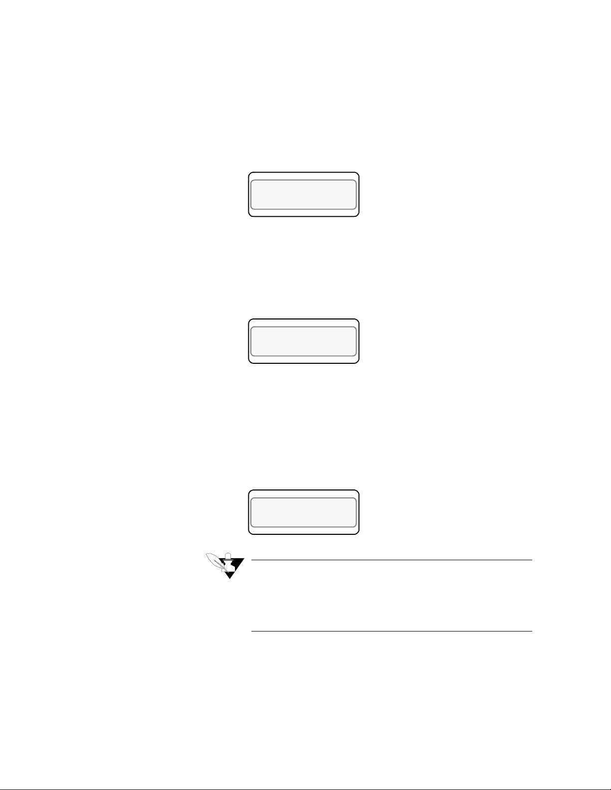
Setup
LOOP PROCESS UNITS
ALARM SETPOINT STATUS OUT%
LOOP PROCESS UNITS
ALARM SETPOINT STATUS OUT%
LOOP PROCESS UNITS
ALARM SETPOINT STATUS OUT%
High Process Alarm Setpoint
Use this menu to select the setpoint (temperature or other value within
the scaled sensor range) at which the high process alarm activates. The
high process alarm activates when the process variable (PV) goes above
the high process setpoint. It deactivates when the PV goes below the
high process setpoint minus the deadband value, if you have set a
deadband value.
04 HI PROC ALARM
º
SETPT ? 1000
F
Selectable range:
High Process Alarm Type
Use this menu to turn off the high process alarm or set it to the alarm or
control function. (See the previous description for an explanation of
these choices).
02 HI PROC ALARM
TYPE ? OFF
Selectable values:
High Process Alarm Output Number
Use this menu to choose the digital output that activates when the loop
is in high process alarm. You can use this output to activate a second
alarm horn or buzzer. You can also use it to control your process. For
example, you can set the output you have chosen to activate heating or
cooling mechanisms, or to turn off the system.
01 HI PROC ALARM
OUTPUT ? NONE
any point within the scaled sensor range.
Off, Alarm, or Control.
90 CLS User’s Guide
NOTE
All digital outputs are OR'd together (combined). Therefore you can assign more than one alarm to the same
output number, and that output will be On if any of those
alarms is On.
Selectable values:
not already used for control or the SDAC clock, or you may select
None.
any output number between 1 and 34, as long as it's
Page 99

Deviation Band Value
LOOP PROCESS UNITS
ALARM SETPOINT STATUS OUT%
LOOP PROCESS UNITS
ALARM SETPOINT STATUS OUT%
LOOP PROCESS UNITS
ALARM SETPOINT STATUS OUT%
Setup
Use this menu to set the deviation bandwidth, a positive and negative
alarm or control point relative to the setpoint. If the setpoint changes,
the alarm or control points also change. You can assign a separate
digital output to the high and low deviation alarm/control setpoints--so
that, for example, a high deviation alarm turns on a fan and a low
deviation alarm turns on a heater.
02 DEV ALARM
º
VALUE ? 5
F
Selectable values:
way you set up the Input menus.
High Deviation Alarm Type
Use this menu to disable the high deviation alarm function or set it to the
alarm or control function. (The high deviation alarm activates if the
process value (PV) rises above the deviation band value, and remains
active until the PV goes below the deviation band value minus the
deadband value.)
03 HI DEV ALARM
TYPE ? OFF
Selectable values:
High Deviation Alarm Output Number
Use this menu to assign a digital output which activates when the loop is
in high deviation alarm. The digital output only activates if you have set
the high deviation alarm type to Alarm or Control.
01 HI DEV ALARM
OUTPUT ? NONE
0-255, 25.5, 2.55, .255 or .0255, depending on the
Alarm, Control, Off
NOTE
All digital outputs are OR'd together (combined). Therefore you can assign more than one alarm to the same
output number, and that output will be On if any of those
alarms is On.
Selectable values:
output is not already used for control or the SDAC clock, or you may
select None.
Any output number between 1 and 34, as long as that
CLS User’s Guide 91
Page 100

Setup
LOOP PROCESS UNITS
ALARM SETPOINT STATUS OUT%
LOOP PROCESS UNITS
ALARM SETPOINT STATUS OUT%
LOOP PROCESS UNITS
ALARM SETPOINT STATUS OUT%
Low Deviation Alarm Type
Use this menu to turn Off the low deviation alarm or set it to Alarm or
Control mode.
01 LO DEV ALARM
TYPE ? OFF
Selectable values:
Low Deviation Alarm Output Number
Use this menu to assign a digital output that activates when the loop is
in low deviation alarm.
04 LO DEV ALARM
OUTPUT ? NONE
NOTE
All digital outputs are OR'd together (combined). Therefore you can assign more than one alarm to the same
output number, and that output will be On if any of those
alarms is On.
Selectable values:
for control or the SDAC clock, or you may select None.
Low Process Alarm Setpoint
Off, Alarm, or Control.
1 and 34, as long as that output is not already used
92 CLS User’s Guide
Use this menu to set a low process alarm setpoint. The low process
alarm activates when the process variable goes below the low process
alarm setpoint. It deactivates when the process variable goes above the
low process alarm setpoint plus the deadband.
01 LO PROC ALARM
º
SETPT ? 0
Selectable range:
F
Any value within the input sensor's range.
 Loading...