

Page 1
W A T L O W
Tubular and
Process Assemblies
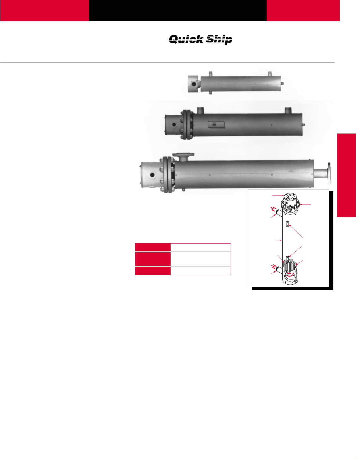
Circulation Heaters
Circulation heaters provide a readymade means to install electric
heating with a minimal amount of
time and labor. This is
accomplished by combining
heating elements, vessel, insulation,
terminal enclosure, mounting
brackets and inlet and outlet
connections into a complete
assembly.
Made from NPT screw plug or ANSI
flange heater assemblies mated
with a pressure vessel (tank),
circulation heaters are designed to
heat forced-circulation air, gases or
liquids. Ideal for either in-line or
side-arm operations, these
assemblies direct fluids past
FIREBAR
elements, to deliver fast response
and even heat distribution.
Watlow can meet virtually all your
circulation heater assembly needs
with made-to-order units. Made-toorder units can be made from a
wide range of heating element
sheath materials, wattages, vessel
sizes and materials, pressure
ratings, terminal enclosures and
controls.
Performance Capabilities
• Watt densities to 120 W/in
(18.6 W/cm2)
• Wattages to one megawatt
•UL
recognition to 480VÅ(ac) and
600VÅ(ac) respectively
• Ratings to 600 lb pressure class
• Incoloy®sheath temperatures to
1600°F (870°C)
• Passivated 316 stainless steel
sheath temperatures to 1200°F
(650°C)
• Steel sheath temperatures to
750°F (400°C)
• Copper sheath temperatures to
350°F (175°C)
®
or WATROD heating
®
and CSA component
2
Features and Benefits
• Standard screw plugs and
flanges feature a wide selection
of WATROD and FIREBAR
elements to meet specific
application requirements.
Type Sizes (inch)
NPT 1
Screw Plugs
ANSI flanges 3, 4, 5, 6, 8, 10, 12, 14
1
⁄4, 21⁄2
• Flange ratings meet recognized
agency standards. ANSI B16.5
Class 150 on:
Four or six inch FIREBAR
element flanges
Three to 14 inch WATROD
element flanges
• FIREBAR assemblies pack
more wattage in a smaller heater
bundle—replaces larger flanges
with round tubular elements, with
a smaller package.
• Compacted MgO insulation
filled elements maximize
dielectric strength, heat transfer
and life.
• One inch (25 mm) thermal
insulation, rated to 750°F
(400°C), reduces heat loss from
the vessel.
On stock chart units:
• Five to seven working days on all Assembly Stock
heaters
• 10 working days on special voltages and/or
wattages
• 15 working days on special element lengths
Flange
Assembly
Threaded
Pipe Outlet
Jacket
1" (25 mm)
Insulation
Threaded
Pipe Inlet
Gasket
Mounting
Lugs
Pressure
Vessel
• Heavy-gauge steel jacket
(shroud) protects thermal
insulation and heating vessel.
Comes with protective primer
coating.
• All catalog units rated to ANSI
pressure Class 150. Pressure
vessels (tanks) are either carbon
or 316 stainless steel.
• NPT or ANSI Class 150 nozzle
connections make installation
easy. Inlet and outlet nozzle
connections are:
Threaded MNPT on eight inch
and smaller tanks
Class 150 flanged connections
on 10 inch and larger tanks
Circulation Heaters
UL®is a registered trademark of
Underwriter's Laboratories, Inc.
Incoloy®is a registered trademark of
Special Metals Corporation.
367
Page 2
Tubular and
Ref
T
Process Assemblies
Circulation Heaters
Features and Benefits
• Mounting lugs are welded onto
the tank wall of all 21⁄2
and larger units. Lugs are flush
with outer insulation jacket and
provide mounting support.
Applications
• Water:
Deionized
Demineralized
Clean
Potable
Process
Options
Terminal Enclosures
General purpose (NEMA 1) terminal
enclosures, without thermostats, are
supplied on all Watlow circulation
heaters. Moisture and explosion
resistant ratings are available to
meet specific application needs. For
screw plug terminal enclosures,
inch NPT
• Flange mounting holes straddle
centerline to comply with industry
standards.
• Standard, general purpose
(NEMA 1) terminal enclosures
offer easy access to terminal
wiring.
• Industrial water rinse tanks
• Hydraulic oil, crude, asphalt
• Lubricating oils at API specified
watt densities
• Heat transfer oil
refer to pages 322 to 324. For
flange terminal enclosures, refer to
pages 340 to 341.
Stand-off Terminal Enclosures
Stand-off terminal enclosures help
protect terminal enclosures against
excessive temperatures. For details,
refer to page 340.
®
• UL
and CSA component
recognition under file numbers
E52951 and 31388 respectively.
See pages 268 to 271 for details.
• Branch circuits are subdivided
by National Electric Code (NEC)
requirements to a maximum of
48 amps per circuit.
• Paraffin
• Caustic cleaners
• Nitrogen, hydrogen and other
air/gas systems
• Superheating steam
CSA Certified Enclosures
To meet agency recognition
requirements, CSA certified
moisture and/or explosion resistant
terminal enclosures are available.
Consult your Watlow representative
for details.
Thermostats
To provide process temperature
control, Watlow offers optional
single and double pole thermostats.
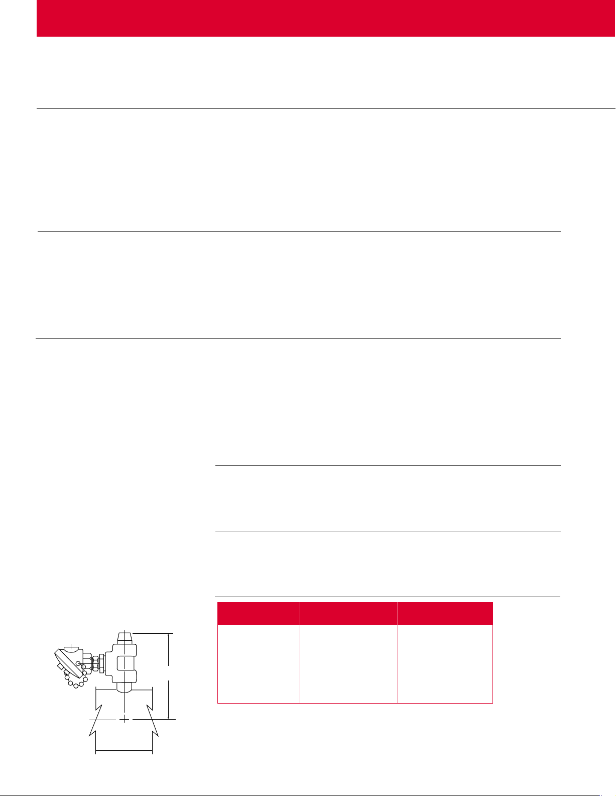
Process Thermocouple in Nozzle
(Must specify which nozzle)
Thermostats are typically mounted
in the terminal enclosure. Optional
side mounting on vessel also
available.
Thermocouples
To sense process or element sheath
temperature, ASTM Type J or K
thermocouples are available.
Ref. Ref. Dimension
Tank Size Nozzle Size "A"
1
1
⁄4
2 1⁄2
3 1 NPT 8 3⁄16
41
5 2 NPT 11 1⁄16
62
82
For 10 inch and larger tanks consult factory for dimension.
3
⁄4 NPT 8 3⁄16
1 NPT 8
1
⁄2 NPT 10 3⁄8
1
⁄2 NPT 13 3⁄8
1
⁄2 NPT 14 3⁄8
See Screw Plug Immersion
Heaters, page 324, and Flange
Immersion Heaters, on page 342
for details.
See Screw Plug Immersion
Heaters, page 325 and Flange
Immersion Heaters, on page 342
for details.
3
⁄16
368
Page 3
W A T L O W
Tubular and
Process Assemblies
Circulation Heaters
Options
Continued
Branch Circuits
Branch circuits are subdivided by
National Electrical Code (NEC)
requirements to a maximum of
Wattages and Voltages
Watlow routinely supplies circulation
heaters with 120 to 480VÅ(ac) as
well as wattages from 500 watts to
one megawatt. If required, Watlow
will configure circulation heaters
48 amps per circuit. Consult factory
for circuit requirements other than
those listed in the stock charts.
with voltages and wattages outside
these parameters.
For more information on special
voltage and wattage configurations,
consult your Watlow representative.
Circulation Heaters
Sheath Materials
The following sheath materials are
available on WATROD and
FIREBAR heating elements:
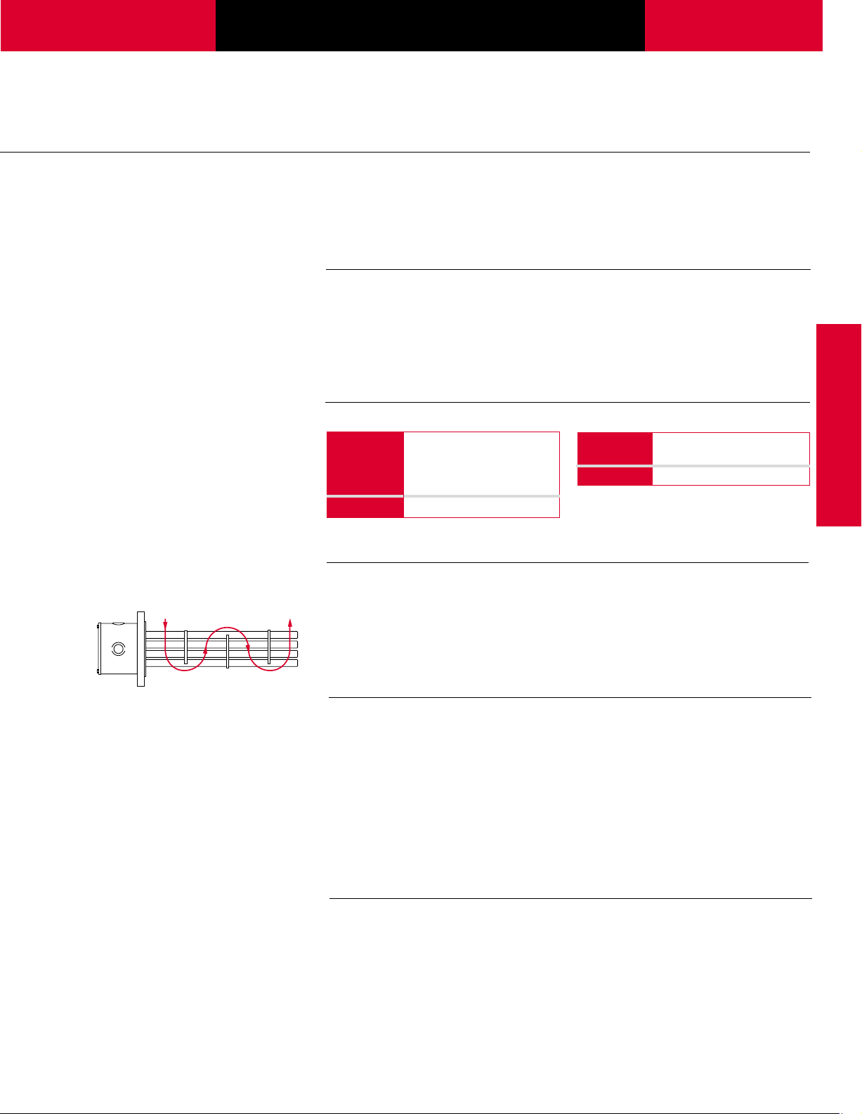
Baffles
Direction of Flow
Pressure Vessels
All standard pressure vessel (tank)
materials are rated to 150 lb and
made from:
• Carbon steel
• 316 stainless steel
All catalog pressure vessels (tanks)
are steel unless otherwise noted.
Standard Sheath Materials
WATROD Incoloy
FIREBAR Incoloy
®
316 stainless steel
Steel
Copper
®
Baffles mounted on the heating
element bundle enhance and/or
modify liquid or gas flow for better
heat transfer.
316 stainless steel pressure
vessels (tanks) are passivated on all
wetted surfaces. Available from
Assembly Stock on 2
1
⁄2 inch NPT
and four or six inch ANSI flange
circulation heaters.
Made-to-order units can be made in
a variety of materials, flange sizes
and pressure classes.
Made-to-Order Sheath Materials
WATROD 304 stainless steel
FIREBAR 304 stainless steel
Monel
®
Exotic Sheath Materials
Consult your Watlow representative
for details and availability.
For critical sheath temperature and
low flow conditions, baffles may be
required.
Consult your Watlow representative
for details.
To order, specify pressure
vessel (tank) size, material and
pressure class.
ANSI ratings to 600 lb are available
for high-pressure applications. For
pressure class ratings above
600 lb, as well as other vessel
materials, consult Watlow Process
Systems in Troy, Missouri.
Monel®is a registered trademark of
Special Metals Corporation.
Passivated Finish
For critical applications, passivation
will remove free iron from all wetted
surfaces.
Consult factory for details.
369
Page 4

Tubular and
Process Assemblies
Circulation Heaters
Options
ontinued
C
Gaskets
Rubber, asbestos-free and spiral
wound gaskets are available for all
heater flange, and inlet and outlet
flange sizes.
Watlow recommends ordering
spares in case replacement
becomes necessary.
and Outlet Nozzle Connections
Inlet
All inlet and outlet materials are
compatible with the pressure vessel
material and pressure class rating.
Vessel sizes from 11⁄4 to eight inches
are typically configured with MNPT
(Male National Pipe Thread)
nozzles. Optional NPT and flange
sizes can be supplied to mate with
existing piping.
To order, specify gasket type,
flange size/rating and process
operating temperature.
For details on gasket materials and
temperature ratings, see page 343.
10 inch and larger vessels are
supplied with Class 150 inlet and
outlet flanges. Optional Class 300 or
Class 600 can be provided to mate
with existing piping.
To order, specify type, size and
pressure class rating for both inlet
and outlet nozzle/flange
connections.
High Temperature Thermal Insulation
To further minimize heat loss, the
pressure vessel’s standard one inch
thermal insulation wrap may be
replaced with thicker or higher
temperature insulation. For more
information, consult your Watlow
representative.
Protective Steel Jacket (Shroud)
To protect circulation heaters from
weather or wash-down conditions,
fully welded (weatherproof) or
partially welded (standard) outer
protective steel jackets are
available. Standard steel, or madeto-order 304 or 316 stainless steel
Support Saddles
To mate with an existing installation,
customized support saddle(s)
and/or mounting lugs are available.
To order, specify insulation
thickness, standard or high
temperature insulation and
temperature rating.
Vessels may be supplied with a
primer coating without insulation.
To order, specify no insulation.
can be supplied. Jacket diameter is
dependent upon thermal insulation
thickness.
To order, specify protective steel
jacket, material type and
weatherproof, if desired.
To order, specify mounting lugs or
support saddles and supply a
dimensional drawing.
370
Page 5

W A T L O W
Tubular and
Process Assemblies
Circulation Heaters
Maximum V elocities
The rate at which a gas or liquid
flows through inlet and outlet pipes
is critical to maintaining the desired
output temperature. Pressure drop
through the circulation heater must
be considered to properly size
blowers or pumps. The Maximum
Velocity to Avoid Excessive
Pressure Drop chart gives
recommended maximum velocities,
in feet per second and meters per
second of gas or liquid being
heated and nominal pipe size.
Vessel Orientation
Guidelines
Correctly orienting the heating
vessel assures lower terminal
enclosure temperatures and
element immersion. Detailed
instructions on vessel orientation are
contained in the Installation and
Maintenance Instructions that
accompanies all circulation heaters.
The following are guidelines for
vessel orientation in liquid and gas
heating applications.
Maximum Velocity to Avoid Excessive Pressure Drop
Fluid Nominal Pipe Size Maximum Velocity
inch ft/sec (m/sec)
Gases All 200 (61.0)
Liquid 4 and smaller 10 (3.0)
Liquid 6-8 15 (5.0)
Liquid 10-12 19 (6.0)
Liquid 14-16 21 (6.4)
Liquid 18-20 23 (7.0)
Liquid 24 24 (7.3)
Liquids
Orient circulation heater:
• Horizontally with inlet and outlet
pipes pointing up
• Vertically with the terminal
enclosure up and the inlet pipe
on the bottom
These orientations ensure the
heating elements will be immersed
at all times and help prevent
premature failure.
Air or Gases
Orient circulation heater:
• Horizontally with the inlet nozzle
closest to the terminal enclosure.
• Vertically with terminal enclosure
at the bottom of the tank. Use the
nozzle nearest the bottom as the
inlet connection.
If installation constraints do not
allow mounting in accordance with
these guidelines, consult your
Watlow representative.
Circulation Heaters
Application Hints
• Select the recommended heating
element sheath material and watt
density for the substance being
heated. Use the Supplemental
Applications Chart on pages
263 to 266. If unable to
determine the correct heating
element type and material,
consult your Watlow
representative.
• Assure selecting proper vessel by
considering the pressure or flow
rate, process temperature and
corrosiveness of the media being
heated. If assistance with vessel
selection is required, consult your
Watlow representative.
• For maintenance/replacement
procedures, retain an area twice
the circulation heater’s overall
length to permit easy removal
and inspection of screw plug or
flange heater assemblies.
• Choose a FIREBAR assembly
when you require:
A smaller package
More kilowatts or lower watt
density in an equally sized
WATROD circulation tank.
• Minimize problems associated
with low flow or low liquid level
conditions with a low liquid level
sensor and/or sheath high-limit
control.
• Ensure wiring integrity by making
sure terminal enclosure
temperature does not exceed
400°F (205°C).
• Protect against electrical shock
by properly grounding the unit
per NEC requirements.
• One or more circulation heaters
may be connected in series to
achieve the desired total kilowatt
or temperature output.
371
Page 6
Tubular and
3
3
/4
"
(95 mm)
4
"
(100 mm)
Ref
A
Ref
6
7
/16
"
(164 mm)
3
/4
"
NPT Inlet & Outlet
B
Ref
3
1
/8
"
(79 mm)
Ref
C
1
/2
"
NPT
Process Assemblies
Circulation Heaters
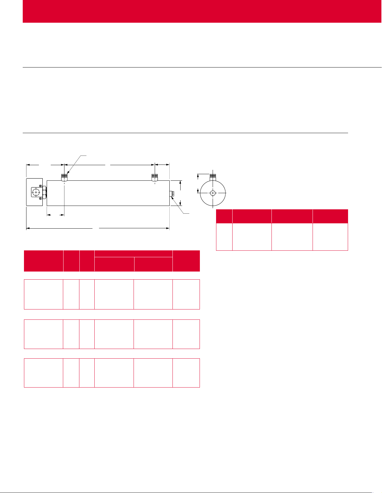
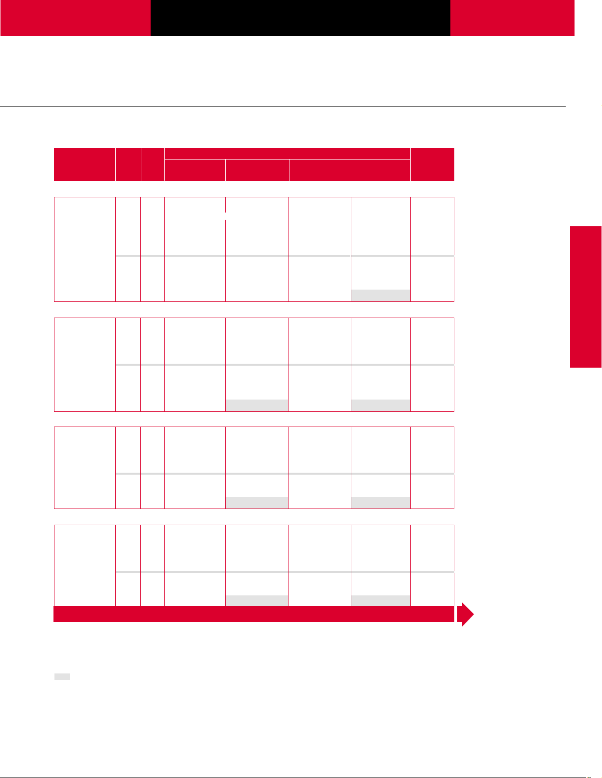
Replacement Heater Assemblies
To help assure minimum process
downtime, it’s advisable to order
and keep on hand a replacement
flange or screw plug heater
assembly.
1
1
4" NPT
⁄
" NPT Screw Plug—WATROD Element
11⁄4
WATROD Code No. Est. Ship.
Description kW Fig. 120/240VÅ(ac) 240VÅ(ac) Weight
No. 1-Phase 1-Phase lbs (kg)
Application: Clean Water
60 W/in2➃ 3.0 1.1 CBEC15A6 23 (11)
Steel Tank 4.0 1.1 CBEC19A10 29 (14)
2-Copper 5.0 1.2 CBEC23J10 29 (14)
(9.3 W/cm2) 6.0 1.2 CBEC27J10 31 (14)
Applications: Forced Air and Gases, Caustic Solutions, Degreasing Solutions
23 W/in2➃ 1.0 1.1 CBEN13G6 21 (10)
Steel Tank 1.5 1.1 CBEN19A6 29 (14)
2-Incoloy
(3.6 W/cm
®
2.0 1.2 CBEN24G6 29 (14)
2
)
Applications: Lightweight Oils, Degreasing Solutions, Heat Transfer Oils
23 W/in2➃ 1.5 1.1 CBES19G6 29 (14)
Steel Tank 2.0 1.2 CBES25G6 29 (14)
2-Steel
(3.6 W/cm2)
All circulation heaters are Assembly Stock
unless otherwise noted.
Availability
Assembly Stock: Five to seven working days
Standard: 10 working days
Spare and/or replacement screw
plug or flange heaters can be
ordered by simply providing the
Fig. A Dimension B Dimension C Dimension
No. in (mm) in (mm) in (mm)
1.1 245⁄
1.2 32
1.3 425⁄8 (1083) 32 (813) 4 (102)
1.4 635⁄
➃ Wired for higher voltage.
F.O.B.: Hannibal, Missouri
complete circulation heater code
number and specifying
“replacement heater only.”
8 (625) 15 (381) 3
5
⁄8 (829) 23 (584) 3 (76)
8 (1616) 53 (1346) 4 (102)
1
8 (79)
⁄
372
Page 7
W A T L O W
Tubular and
Process Assemblies
Circulation Heaters
11⁄4" NPT Screw Plug—FIREBAR Element
FIREBAR Code No. Est. Ship.
Description kW Fig. 240VÅ(ac) 240VÅ(ac) 480VÅ(ac) 480VÅ(ac) Weight
No. 1-Phase 3-Phase 1-Phase 3-Phase lbs (kg)
Applications: Clean and Potable Water
90 W/in2➇ 1.5 1.1 CBDNF7R10bg CBDNF7R11bg 26 (12)
Steel Tank 3.0 1.1 CBDNF11G10bg CBDNF11G11b 26 (12)
1-Incoloy
(14 W/cm
Applications: Process Water, Ethylene Glycol (50%)
45 W/in2➇ 2.0 1.1 CBDNF13A27 25 (12)
Steel Tank 2.5 1.1 CBDNF15J27 26 (12)
1-Incoloy
(7 W/cm2) 4.0 1.2 CBDNF22J27 CBDNF22J28 31 (14)
Applications: Cooking Oils, Ethylene Glycol (100%)
30 W/in2➂ 1.7 1.1 CBDNF16G12 CBDNF16G13 26 (12)
Steel Tank 2.2 1.2 CBDNF19G12 CBDNF19G13 30 (14)
1-Incoloy
(4.7 W/cm2) 3.5 1.3 CBDNF29R12 CBDNF29R13 43 (20)
Applications: Heat Transfer Oils, Lubrication Oils, Mineral Oil, Degreasing Solutions
23 W/in2➇ 1.25 1.1 CBDNF16G20 26 (12)
Steel Tank 1.65 1.2 CBDNF19G20 30 (14)
1-Incoloy
(3.6 W/cm2) 2.65 1.3 CBDNF29R20 CBDNF29R19 43 (20)
®
5.0 1.1 CBDNF16G3 CBDNF16G5 26 (12)
2
) 6.5 1.2 CBDNF19G3 CBDNF19G5 30 (14)
8.5 1.2 CBDNF24L3 CBDNF24L5 31 (14)
10.5 1.3 CBDNF29R3 CBDNF29R5 43 (20)
12.75 1.3 CBDNF34R3 CBDNF34R5 44 (20)
17.0 1.4 CBDNF45G3 CBDNF45G5 69 (32)
21.5 1.4 CBDNF55R5 71 (33)
®
3.0 1.2 CBDNF18A27 30 (14)
5.0 1.3 CBDNF27J27 CBDNF27J28 43 (20)
6.0 1.3 CBDNF32J27 CBDNF32J28 44 (20)
8.0 1.4 CBDNF42A27 CBDNF42A28 69 (32)
10.0 1.4 CBDNF51J27 CBDNF51J28 71 (33)
®
2.8 1.2 CBDNF24L12 CBDNF24L13 31 (14)
4.25 1.3 CBDNF34R12 CBDNF34R13 44 (20)
5.7 1.4 CBDNF45G12 CBDNF45G13 69 (32)
7.2 1.4 CBDNF55R12 CBDNF55R13 71 (33)
®
2.15 1.2 CBDNF24L20 CBDNF24L19 31 (14)
3.20 1.3 CBDNF34R20 CBDNF34R19 44 (20)
4.25 1.4 CBDNF45G20 CBDNF45G19 69 (32)
5.40 1.4 CBDNF55R20 CBDNF55R19 71 (33)
CONTINUED
Circulation Heaters
All circulation heaters are Assembly Stock
unless otherwise noted.
Availability
Assembly Stock: Five to seven working days
Standard: 10 working days
Truck Shipment only
b Standard
c Must be operated 3-phase wye.
g Available in 1-phase only.
h Can be wired 1-phase.
373
Page 8
Tubular and
3
1
/8
"
(79 mm)
Ref
A
4
3
/8
"
(111 mm)
5
5
/8
"
(143 mm)
Ref
4
15
/16
"
(125 mm)
1" NPT Inlet & Outlet
3
/8
"
- 16 UNC Thread
(4 places)
3
/4
"
deep (19 mm)
Ref
3
1
/2
"
(89 mm)
11
3
/16
"
(284 mm)
C
1
1
/4
"
(32 mm)
1
/2
"
NPT
B
1
/2
"
NPT
7
3
/16
"
(183 mm)
Process Assemblies
Circulation Heaters
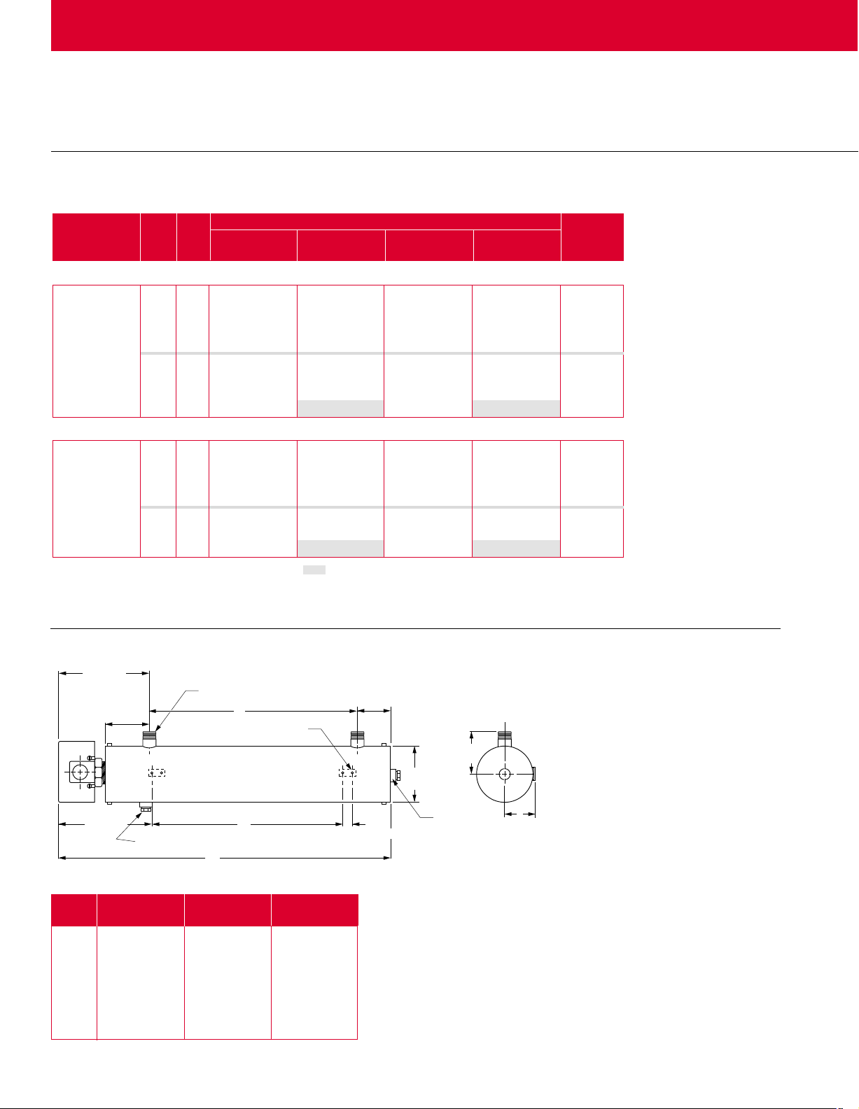
" NPT Screw Plug—FIREBAR Element
11⁄4
FIREBAR Code No. Est. Ship.
Description kW Fig. 240VÅ(ac) 240VÅ(ac) 480VÅ(ac) 480VÅ(ac) Weight
No. 1-Phase 3-Phase 1-Phase 3-Phase lbs (kg)
Applications: Medium Weight Oils, Heat Transfer Oils, Lube Oils, Liquid Paraffin
15 W/in2➂ 0.67 1.1 CBDNF13A29 25 (12)
Steel Tank 0.83 1.1 CBDNF15J29 26 (12)
1-Incoloy
(2.3 W/cm2) 1.33 1.2 CBDNF22J29 CBDNF22J30 31 (14)
Applications: Bunker C and #6 Fuel Oils, Asphalt
8 W/in2➂ 0.43 1.1 CBDNF16G22 26 (12)
Steel Tank 0.55 1.2 CBDNF19G22 30 (14)
1-Incoloy
(1.3 W/cm2) 0.88 1.3 CBDNF29R22 CBDNF29R21 43 (20)
All circulation heaters are Assembly Stock
unless otherwise noted.
Availability
Assembly Stock: Five to seven working days
Standard: 10 working days
®
1.00 1.2 CBDNF18A29 30 (14)
1.67 1.3 CBDNF27J29 CBDNF27J30 43 (20)
2.00 1.3 CBDNF32J29 CBDNF32J30 44 (20)
2.67 1.4 CBDNF42A29 CBDNF42A30 69 (32)
3.30 1.4 CBDNF51J29 CBDNF51J30 71 (33)
®
0.70 1.2 CBDNF24L22 CBDNF24L21 31 (14)
1.08 1.3 CBDNF34R22 CBDNF34R21 44 (20)
1.40 1.4 CBDNF45G22 CBDNF45G21 69 (31)
1.80 1.4 CBDNF55R22 CBDNF55R21 71 (32)
Truck Shipment only
➂ Must be operated 3-phase wye only.
2" NPT
21⁄
1
2
⁄2" NPT Screw Plug
Fig. A Dimension B Dimension C Dimension
No. in (mm) in (mm) in (mm)
2.1 3411⁄16 (881) 221⁄2 (572) 161⁄2 (419)
2.2 4411⁄16 (1135) 321⁄2 (1129) 261⁄2 (673)
2.3 573⁄
2.4 63
16 (1453) 45 (1143) 39 (991)
11
⁄16 (1618) 511⁄2 (1308) 461⁄2 (1181)
2.5 3411⁄16 (881) 221⁄2 (572) 161⁄2 (419)
374
2.6 4411⁄
2.7 57
(1135) 32
16
3
⁄16 (1453) 45 (1143) 39 (991)
1
(1129) 26
2
⁄
1
2
⁄
(673)
Page 9
W A T L O W
Tubular and
Process Assemblies
Circulation Heaters
21⁄2" NPT Screw Plug—WATROD Element
WATROD Code No. Est. Ship.
Description kW Fig. 240VÅ(ac) 480VÅ(ac) Weight
No. 3-Phase 3-Phase lbs (kg)
Application: Clean Water
2
60 W/in
Steel Tank 7.5 2.5 CBLC717L3 CBLC717L5 24 (11)
3-Copper 9.0 2.5 CBLC720L3 CBLC720L5 26 (12)
(9.3 W/cm2) 12.0 2.6 CBLC726C3 CBLC726C5 27 (13)
Application: Deionized Water , Demineralized Water
2
60 W/in
316 SS Tank 7.5 2.5 CBLR717L3 CBLR717L5 24 (11)
3-316 SS 9.0 2.5 CBLR720L3 CBLR720L5 26 (12)
(9.3 W/cm2) 12.0 2.6 CBLR726C3 CBLR726C5 27 (13)
Passivated 15.0 2.6 CBLR731L3 CBLR731L5 29 (14)
Application: Process Water
2
48 W/in
Steel Tank 7.5 2.5 CBLN719R3 CBLN719R5 26 (12)
3-Incoloy
(7.5 W/cm2) 12.0 2.6 CBLN732G3 CBLN732G5 29 (14)
®
Applications: Forced Air and Gases, Caustic Solutions, Degreasing Solutions
23 W/in2➄➅ 3.0 2.5 CBLNA17G3 CBLNA17G5 24 (11)
Steel Tank 4.5 2.6 CBLNA24R3 CBLNA24R5 27 (13)
3-Incoloy
(3.6 W/cm
®
Applications: Lightweight Oils, Degreasing Solutions, Heat Transfer Oils
23 W/in2➅ 3.0 2.5 CBLS717E3 CBLS717E5 24 (11)
Steel Tank 4.5 2.5 CBLS724N3 CBLS724N5 27 (13)
3-Steel 6.0 2.6 CBLS732E3 CBLS732E5 29 (14)
(3.6 W/cm2) 7.5 2.7 CBLS739N3 CBLS739N5 31 (14)
Applications: Medium Weight Oils, Heat Transfer Oils, Lube Oils, Liquid Paraffin
16 W/in2➂ 2.0 2.5 CBLN717G12 CBLN717G13 24 (11)
Steel Tank 2.5 2.5 CBLN719R12 CBLN719R13 26 (12)
3-Incoloy
(2.5 W/cm2) 4.0 2.6 CBLN732G12 CBLN732G13 29 (14)
®
Applications: Bunker C and #6 Fuel Oils
8 W/in2➂ 2.0 2.6 CBLS732E12 CBLS732E13 29 (14)
Steel Tank 3.0 2.7 CBLS747E12 CBLS747E13 32 (15)
3-Steel
(1.3 W/cm2)
6.0 2.5 CBLC714L3 CBLC714L5 24 (11)
15.0 2.6 CBLC731L3 CBLC731L5 29 (14)
18.0 2.7 CBLC737C3 CBLC737C5 30 (14)
6.0 2.5 CBLR714L3 CBLR714L5 24 (11)
18.0 2.7 CBLR737C3 CBLR737C5 30 (14)
6.0 2.5 CBLN717G3 CBLN717G5 24 (11)
9.0 2.5 CBLN724R3 CBLN724R5 27 (13)
15.0 2.7 CBLN739R3 CBLN739R5 31 (14)
18.0 2.7 CBLN747G3 CBLN747G5 32 (15)
6.0 2.6 CBLNA32G3 CBLNA32G5 29 (14)
2
) 7.5 2.7 CBLNA39R3 CBLNA39R5 31 (14)
9.0 2.7 CBLNA47G3 CBLNA47G5 32 (15)
9.0 2.7 CBLS747E3 CBLS747E5 32 (15)
3.0 2.5 CBLN724R12 CBLN724R13 27 (13)
5.0 2.7 CBLN739R12 CBLN739R13 31 (14)
6.0 2.7 CBLN747G12 CBLN747G13 32 (15)
All circulation heaters are Assembly Stock
unless otherwise noted.
Availability
Assembly Stock: Five to seven working days
Standard: 10 working days
➂ Must be operated 3-phase wye only.
➄ 240VÅ(ac) can be wired wye and operated
at 480VÅ(ac) 3-phase to produce 1⁄3 more kW
and watt density.
➅ Can be wired wye to produce 1⁄3 of the
original kW and watt density
(3-phase only).
Circulation Heaters
375
Page 10

Tubular and
Process Assemblies
Circulation Heaters
21⁄2" NPT Screw Plug—FIREBAR Element
FIREBAR Code No. Est. Ship.
Description kW Fig. 240VÅ(ac) 480VÅ(ac) Weight
No. 3-Phase 3-Phase lbs (kg)
Applications: Clean and Potable Water
90 W/in2h 15.0 2.1 CBLNF15C3 CBLNF15C5 22 (10)
Steel Tank 20.0 2.1 CBLNF18C3 CBLNF18C5c 23 (11)
3-Incoloy
(14 W/cm2) 32.0 2.2 CBLNF28L5 34 (16)
Applications: Process Water, Ethylene Glycol (50%)
45 W/in2h 6.0 2.1 CBLNF12A27 21 (10)
Steel Tank 7.5 2.1 CBLNF14J27 22 (10)
3-Incoloy
(7 W/cm2) 12.0 2.1 CBLNF21J27 CBLNF21J28 31 (14)
Applications: Cooking Oils, Ethylene Glycol (100%)
30 W/in2c 5.0 2.1 CBLNF15C12 CBLNF15C13 22 (10)
Steel Tank 6.5 2.1 CBLNF18C12 CBLNF18C13 23 (11)
3-Incoloy
(4.7 W/cm2) 10.5 2.2 CBLNF28L12 CBLNF28L13 34 (16)
Applications: Heat Transfer Oils, Mineral Oil, Degreasing Solutions
23 W/in2h 3.8 2.1 CBLNF15C20 22 (10)
Steel Tank 4.9 2.1 CBLNF18C20 23 (11)
3-Incoloy
(3.6 W/cm2) 7.9 2.2 CBLNF28L20 CBLNF28L19 34 (16)
Applications: Medium Weight Oils, Heat Transfer Oils, Lube Oils, Liquid Paraffin
15 W/in2c 2.0 2.1 CBLNF12A29 21 (10)
Steel Tank 2.5 2.1 CBLNF14J29 22 (10)
3-Incoloy
(2.3 W/cm2) 4.0 2.1 CBLNF21J29 CBLNF21J30 31 (14)
Applications: Bunker C and #6 Fuel Oils, Asphalt
8 W/in2c 1.25 2.1 CBLNF15C22 22 (10)
Steel Tank 1.63 2.1 CBLNF18C22 23 (10)
3-Incoloy
(1.3 W/cm2) 2.63 2.2 CBLNF28L22 CBLNF28L21 34 (15)
®
25.0 2.1 CBLNF23C5 31 (14)
38.0 2.2 CBLNF33L5 35 (16)
®
®
®
®
®
9.0 2.1 CBLNF17A27 23 (11)
15.0 2.2 CBLNF26J27 CBLNF26J28 34 (16)
18.0 2.2 CBLNF31J27 CBLNF31J28 35 (16)
24.0 2.3 CBLNF41A28 44 (20)
30.0 2.4 CBLNF50J28 52 (24)
8.5 2.1 CBLNF23C12 CBLNF23C13 31 (14)
12.8 2.2 CBLNF33L12 CBLNF33L13 35 (16)
17.0 2.3 CBLNF44C12 CBLNF44C13 44 (20)
21.5 2.4 CBLNF54L13 52 (24)
6.4 2.1 CBLNF23C20 CBLNF23C19 31 (14)
9.6 2.2 CBLNF33L20 CBLNF33L19 35 (16)
12.8 2.3 CBLNF44C20 CBLNF44C19 44 (20)
16.1 2.4 CBLNF54L20 CBLNF54L19 52 (24)
3.0 2.1 CBLNF17A29 23 (11)
5.0 2.2 CBLNF26J29 CBLNF26J30 34 (16)
6.0 2.2 CBLNF31J29 CBLNF31J30 35 (16)
8.0 2.3 CBLNF41A29 CBLNF41A30 44 (20)
10.0 2.4 CBLNF50J29 CBLNF50J30 52 (24)
2.13 2.1 CBLNF23C22 CBLNF23C21 31 (14)
3.19 2.2 CBLNF33L22 CBLNF33L21 35 (16)
4.25 2.3 CBLNF44C22 CBLNF44C21 44 (20)
5.38 2.4 CBLNF54L22 CBLNF54L21 52 (24)
All circulation heaters are Assembly Stock
unless otherwise noted.
Availability
Assembly Stock: Five to seven working days
Standard: 10 working days
Note: Assembly Stock may be shipped same
day if ordered before 11:00 am CST.
c Must be operated 3-phase wye only.
h Can be wired 1-phase.
376
Page 11
W A T L O W
Ref
A
5
5
/8
"
(143 mm)
4
1
/8
"
(105 mm)
1" NPT Inlet & Outlet
3
/8
"
- 16 UNC Thread
(4 places)
3
/4
"
(19 mm) deep
(2 places)
1
1
/4
"
(32 mm)
Ref
5
"
(127 mm)
Ref
7
11
/16
"
(195 mm)
Ref
11
1
/2
"
(292 mm)
C
B
1
/2
"
NPT
1
/2
"
NPT
3
1
/8
"
(79 mm)
4
3
/8
"
(111 mm)
Tubular and
Process Assemblies
Circulation Heaters
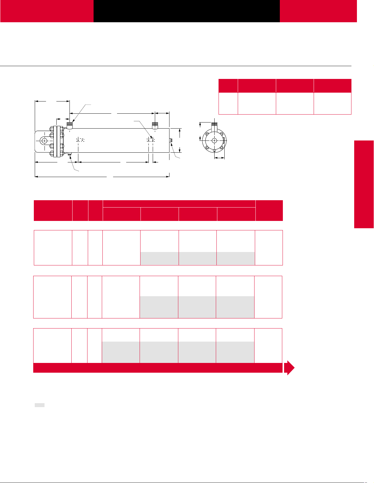
3" Flange
3" 150 lb ANSI Flange—WATROD Element
Fig. A Dimension B Dimension C Dimension
No. in (mm) in (mm) in (mm)
3.1 35
3.2 45
3.3 57
3
16 (894) 22
⁄
3
⁄16 (1148) 321⁄2 (826) 261⁄2 (673)
11
⁄16 (1465) 45 (1143) 39 (991)
1
2 (573) 16
⁄
1
2 (419)
⁄
Circulation Heaters
WATROD Code No. Est. Ship.
Description kW Fig. 240VÅ(ac) 240VÅ(ac) 480VÅ(ac) 480VÅ(ac) Weight
No. 1-Phase 3-Phase 1-Phase 3-Phase lbs (kg)
Application: Clean Water
2
60 W/in
6.0 3.1 CFMC715J10 CFMC715J3 CFMC715J11 CFMC715J5 66 (30)
Steel Tank 9.0 3.1 CFMC721J10 CFMC721J3 CFMC721J11 CFMC721J5 70 (32)
3-Copper 12.0 3.2 CFMC727A3 CFMC727A11 CFMC727A5 80 (37)
2
(9.3 W/cm
) 15.0 3.2 CFMC732J3 CFMC732J11 CFMC732J5 96 (44)
18.0 3.3 CFMC738A3 CFMC738A11 CFMC738A5 98 (45)
Application: Process Water
48 W/in2➄ 6.0 3.1 CFMN718A10 CFMN718A3 CFMN718A11 CFMN718A5 68 (31)
Steel Tank 7.5 3.1 CFMN720J10 CFMN720J3 CFMN720J11 CFMN720J5 70 (32)
®
3-Incoloy
(7.5 W/cm
9.0 3.2 CFMN725J10 CFMN725J3 CFMN725J11 CFMN725J5 78 (36)
2
) 12.0 3.2 CFMN733A3 CFMN733A11 CFMN733A5 96 (44)
15.0 3.3 CFMN740J3 CFMN740J11 CFMN740J5 100 (46)
18.0 3.3 CFMN748A3 CFMN748A11 CFMN748A5 107 (49)
Applications: Forced Air and Gases, Caustic Solutions, Degreasing Solutions
23 W/in2➄➅ 3.0 3.1 CFMNA18A10 CFMNA18A3 CFMNA18A11 CFMNA18A5 68 (31)
Steel Tank 4.5 3.2 CFMNA25J10 CFMNA25J3 CFMNA25J11 CFMNA25J5 78 (36)
3-Incoloy
(3.6 W/cm2) 7.5 3.3 CFMNA40J10 CFMNA40J3 CFMNA40J11 CFMNA40J5 100 (46)
All circulation heaters are Assembly Stock
unless otherwise noted.
Availability
Assembly Stock: Five to seven working days
Standard: 10 working days
®
6.0 3.2 CFMNA33A10 CFMNA33A3 CFMNA33A11 CFMNA33A5 96 (44)
9.0 3.3 CFMNA48A10 CFMNA48A3 CFMNA48A11 CFMNA48A5 107 (49)
Truck Shipment only
➄ 240VÅ(ac) can be wired wye and
operated at 480VÅ(ac) 3-phase to
produce
➅ Can be wired wye to produce
original kW and watt density
(3-phase only).
1
more kW and watt density.
3
⁄
1
3
⁄
of the
CONTINUED
377
Page 12

Tubular and
Process Assemblies
Circulation Heaters
3" 150 lb ANSI Flange—WATROD Element
WATROD Code No. Est. Ship.
Description kW Fig. 240VÅ(ac) 240VÅ(ac) 480VÅ(ac) 480VÅ(ac) Weight
No. 1-Phase 3-Phase 1-Phase 3-Phase lbs (kg)
Applications: Lightweight Oils, Degreasing Solutions, Heat Transfer Oils
2
23 W/in
Steel Tank 4.5 3.1 CFMS725J10 CFMS725J3 CFMS725J11 CFMS725J5 78 (36)
3-Steel 6.0 3.2 CFMS733A10 CFMS733A3 CFMS733A11 CFMS733A5 96 (44)
(3.6 W/cm2) 7.5 3.3 CFMS740J10 CFMS740J3 CFMS740J11 CFMS740J5 100 (46)
Applications: Medium Weight Oils, Heat Transfer Oils, Lube Oils, Liquid Paraffin
16 W/in2➂ 2.0 3.1 CFMN718A12 CFMN718A13 68 (31)
Steel Tank 2.5 3.1 CFMN720J12 CFMN720J13 70 (32)
3-Incoloy
(2.6 W/cm
Applications: Bunker C and #6 Fuel Oils
8 W/in2➂ 2.0 3.2 CFMS733A12 CFMS733A13 96 (44)
Steel Tank 3.0 3.3 CFMS748A12 CFMS748A13 107 (49)
3-Steel
(1.3 W/cm2)
All circulation heaters are Assembly Stock
unless otherwise noted.
Availability
Assembly Stock: Five to seven working days
Standard: 10 working days
Truck Shipment only
3.0 3.1 CFMS718A10 CFMS718A3 CFMS718A11 CFMS718A5 68 (31)
9.0 3.3 CFMS748A10 CFMS748A3 CFMS748A11 CFMS748A5 107 (49)
®
3.0 3.2 CFMN725J12 CFMN725J13 78 (36)
2
) 4.0 3.2 CFMN733A12 CFMN733A13 96 (44)
5.0 3.3 CFMN740J12 CFMN740J13 100 (46)
6.0 3.3 CFMN748A12 CFMN748A13 107 (49)
➂ Must be operated 3-phase wye only.
378
Page 13

W A T L O W
Tubular and
Process Assemblies
Circulation Heaters
4" Flange
Fig. A Dimension B Dimension C Dimension
No. in (mm) in (mm) in (mm)
15
4.1 38
⁄16 (989) 201⁄2 (521) 17 (432)
4.2 497⁄16 (1256) 31 (787) 271⁄2 (699)
Ref
12
(321 mm)
11
/16
4
(119 mm)
5
"
/8
"
Ref
14
(365 mm)
/16
"
4.3 70
4.4 91
3
(94 mm)
1
"
1
/2
NPT Inlet & Outlet
B
3
"
/8
- 16 UNC Thread
3
"
(19 mm) deep
Ref
/4
C
A
(4 places)
3
"
/8
1
"
/2
NPT
Ref
11
/16
5
(144 mm)
(2 places)
1
(32 mm)
"
1
"
/4
5
"
6
/8
(168 mm)
1
/2
"
NPT
13
5
(148 mm)
7
⁄16 (1789) 52 (1321) 481⁄2 (1232)
7
⁄16 (2326) 73 (1854) 66 (1676)
11
"
/16
4" 150 lb ANSI Flange—WATROD Element
WATROD Code No. Est. Ship.
Description kW Fig. 240VÅ(ac)
No. 1-Phase
No. of
Circuits
240VÅ(ac)
3-Phase
Application: Clean Water
2
60 W/in
12 4.1 CFOC715J10 2 CFOC715J3 1 CFOC715J11 1 CFOC715J5 1 124 (57)
Steel Tank 18 4.1 CFOC721J10 2 CFOC721J3 1 CFOC721J11 1 CFOC721J5 1 127 (58)
6-Copper 24 4.2 CFOC727A10 2 CFOC727A3 2 CFOC727A11 1 CFOC727A5 1 160 (73)
2
(9.3 W/cm
) 30 4.2 CFOC732J3 2 CFOC732J11 2 CFOC732J5 1 163 (74)
36 4.3 CFOC738A3 2 CFOC738A11 2 CFOC738A5 1 229 (104)
50 4.3 CFOC751A5
60 4.4 CFOC760J5
Application: Deionized Water , Demineralized Water
2
60 W/in
12 4.1 CFOR716A10 1 CFOR716A3 1 CFOR716A11 1 CFOR716A5 1 124 (57)
316 SS Tank 18 4.1 CFOR722A10 2 CFOR722A3 1 CFOR722A11 1 CFOR722A5 1 127 (58)
6-316 SS 24 4.2 CFOR727J10 2 CFOR727J3 2 CFOR727J11 1 CFOR727J5 1 160 (73)
(9.3 W/cm2) 30 4.2 CFOR733A3 2 CFOR733A11 2 CFOR733A5 1 163 (74)
Passivated 36 4.3 CFOR738J3 2 CFOR738J11 2 CFOR738J5 1 229 (104)
50 4.3 CFOR751J5 2 234 (106)
60 4.4 CFOR761A5 2 297 (135)
Application: Process Water
2
48 W/in
Steel Tank 12 4.1 CFON718A10 2 CFON718A3 1 CFON718A11 1 CFON718A5 1 125 (57)
6-Incoloy
(7.5 W/cm
®
2
All circulation heaters are Assembly Stock
unless otherwise noted.
Availability
Assembly Stock: Five to seven working days
Standard:10 working days
Truck Shipment only
9 4.1 CFON713J10 1 CFON713J3 1 CFON713J11 1 CFON713J5 1 122 (56)
15 4.1 CFON720J10 2 CFON720J3 1 CFON720J11 2 CFON720J5 1 127 (58)
) 18 4.1 CFON725J10 2 CFON725J3 1 CFON725J11 1 CFON725J5 1 160 (73)
24 4.2 CFON733A10 2 CFON733A3 2 CFON733A11 1 CFON733A5 1 163 (74)
30 4.3 CFON740J3 2 CFON740J11 2 CFON740J5 1 229 (104)
36 4.3 CFON748A3 2 CFON748A11 2 CFON748A5 1 234 (107)
b Standard
No. of
Circuits
480VÅ(ac)
1-Phase
No. of
Circuits
480VÅ(ac)
3-Phase
No. of
Circuits
b
2 234 (107)
b
2 297 (135)
Weight
lbs (kg)
CONTINUED
Circulation Heaters
379
Page 14

Tubular and
Process Assemblies
Circulation Heaters
4" 150 lb ANSI Flange—WATROD Element
WATROD Code No. Est. Ship.
Description kW Fig. 240VÅ(ac)
No. 1-Phase
No. of
Circuits
240VÅ(ac)
3-Phase
Applications: Forced Air and Gases, Caustic Solutions, Degreasing Solutions
23 W/in2➄➅ 6 4.1 CFONA18A10 1 CFONA18A3 1 CFONA18A11 1 CFONA18A5 1 125 (57)
Steel Tank 9 4.1 CFONA25J10 1 CFONA25J3 1 CFONA25J11 1 CFONA25J5 1 160 (73)
6-Incoloy
(3.6 W/cm2) 15 4.3 CFONA40J10 2 CFONA40J3 1 CFONA40J11 1 CFONA40J5 1 229 (104)
®
12 4.2 CFONA33A10 2 CFONA33A3 1 CFONA33A11 1 CFONA33A5 1 163 (74)
18 4.3 CFONA48A10 2 CFONA48A3 1 CFONA48A11 1 CFONA48A5 1 234 (107)
25 4.4 CFONA64J3 2 CFONA64J11 2 CFONA64J5 1 298 (136)
30 4.4 CFONA77A3 2 CFONA77A11 2 CFONA77A5 1 306 (139)
Applications: Lightweight Oils, Degreasing Solutions, Heat Transfer Oils
2
23 W/in
Steel Tank 9 4.1 CFOS725J10 1 CFOS725J3 1 CFOS725J11 1 CFOS725J5 1 160 (73)
6-Steel 12 4.2 CFOS733A10 2 CFOS733A3 1 CFOS733A11 1 CFOS733A5 1 163 (74)
(3.6 W/cm2) 15 4.3 CFOS740J10 2 CFOS740J3 1 CFOS740J11 1 CFOS740J5 1 229 (104)
6 4.1 CFOS718A10 1 CFOS718A3 1 CFOS718A11 1 CFOS718A5 1 125 (57)
18 4.3 CFOS748A10 2 CFOS748A3 1 CFOS748A11 1 CFOS748A5 1 234 (107)
25 4.4 CFOS764J3 2 CFOS764J11 2 CFOS764J5 1 298 (136)
30 4.4 CFOS777A3 2 CFOS777A11 2 CFOS777A5 1 306 (139)
Applications: Medium Weight Oils, Heat Transfer Oils, Liquid Paraffin
16 W/in2➂ 3 4.1 CFON713J12 1 CFON713J13 1 122 (56)
Steel Tank 4 4.1 CFON718A12 1 CFON718A13 1 125 (57)
6-Incoloy
(2.6 W/cm2) 6 4.1 CFON725J12 1 CFON725J13 1 160 (73)
®
5 4.1 CFON720J12 1 CFON720J13 1 127 (58)
8 4.2 CFON733A12 1 CFON733A13 1 163 (74)
10 4.3 CFON740J12 2 CFON740J13 1 229 (104)
12 4.3 CFON748A12 1 CFON748A13 1 234 (107)
Applications: Bunker C and #6 Fuel Oils
8 W/in2➂ 5 4.3 CFOS740J12 1 CFOS740J13 1 229 (104)
Steel Tank 6 4.3 CFOS748A12 1 CFOS748A13 1 234 (106)
6-Steel 8 4.4 CFOS764J12 1 CFOS764J13 1 298 (135)
(1.3 W/cm2) 10 4.4 CFOS777A12 1 CFOS777A13 1 306 (139)
No. of
Circuits
480VÅ(ac)
1-Phase
No. of
Circuits
480VÅ(ac)
3-Phase
No. of
Circuits
Weight
lbs (kg)
All circulation heaters are Assembly Stock
unless otherwise noted.
Availability
Assembly Stock: Five to seven working days
Standard: 10 working days
Truck Shipment only
380
➂ Must be operated 3-phase wye only.
➄ 240VÅ(ac) can be wired wye and
operated at 480VÅ(ac) 3-phase to
produce 1⁄3 more kW and watt density.
➅ Can be wired wye to produce 1⁄3 of the
original kW and watt density
(3-phase only).
Page 15

W A T L O W
Tubular and
Process Assemblies
Circulation Heaters
4" 150 lb ANSI Flange—FIREBAR Element
FIREBAR Code No. Est. Ship.
Description kW Fig. 240VÅ(ac)
No. 3-Phase
No. of
Circuits
480VÅ(ac)
3-Phase
Applications: Process Water, Ethylene Glycol (50%)
2
45 W/in
Steel Tank 15.0 4.1 CFONF16A27 1 128 (58)
6-Incoloy
(7 W/cm2) 24.0 4.1 CFONF22R27 2 CFONF22R28 1 133 (61)
12.0 4.1 CFONF13G27 1 125 (57)
®
18.0 4.1 CFONF18G27 1 130 (59)
30.0 4.2 CFONF27R27 2 CFONF27R28 1 168 (77)
36.0 4.2 CFONF32R27 2 CFONF32R28 1 170 (78)
48.0 4.3 CFONF42G28 2 236 (107)
60.0 4.3 CFONF51R28 2 240 (109)
Applications: Cooking Oils, Ethylene Glycol (100%)
2
30 W/in
Steel Tank 13.0 4.1 CFONF19J12 1 CFONF19J13 1 130 (59)
6-Incoloy
(4.7 W/cm2) 21.0 4.2 CFONF30A12 2 CFONF30A13 1 168 (77)
10.0 4.1 CFONF16J12 1 CFONF16J13 1 128 (58)
®
17.0 4.1 CFONF24J12 1 CFONF24J13 1 133 (61)
25.5 4.2 CFONF35A12 2 CFONF35A13 1 170 (78)
34.0 4.3 CFONF45J12 2 CFONF45J13 1 236 (107)
43.0 4.3 CFONF56A13 2 240 (109)
Applications: Heat Transfer Oils, Mineral Oils, Degreasing Solutions
23 W/in2➃ 7.5 4.1 CFONF16J20 1 128 (58)
Steel Tank 10.0 4.1 CFONF19J20 1 130 (59)
6-Incoloy
(3.6 W/cm2) 15.8 4.2 CFONF30A20 1 CFONF30A19 1 168 (77)
®
12.8 4.1 CFONF24J20 1 CFONF24J19 1 133 (61)
19.0 4.2 CFONF35A20 1 CFONF35A19 1 170 (78)
25.0 4.3 CFONF45J20 2 CFONF45J19 1 236 (107)
32.3 4.3 CFONF56A20 2 CFONF56A19 1 240 (109)
Applications: Medium Weight Oils, Heat Transfer Oils, Lube Oils, Liquid Paraffin
15 W/in2➂ 4.0 4.1 CFONF13G29 1 125 (57)
Steel Tank 5.0 4.1 CFONF16A29 1 128 (58)
6-Incoloy
(2.3 W/cm2) 8.0 4.1 CFONF22R29 1 CFONF22R30 1 133 (61)
®
6.0 4.1 CFONF18G29 1 130 (59)
10.0 4.2 CFONF27R29 1 CFONF27R30 1 168 (77)
12.0 4.2 CFONF32R29 1 CFONF32R30 1 170 (78)
16.0 4.3 CFONF42G29 1 CFONF42G30 1 236 (107)
20.0 4.3 CFONF51R29 1 CFONF51R30 1 240 (109)
Applications: Bunker C and #6 Fuel Oils, Asphalt
8 W/in2➂ 2.5 4.1 CFONF16J22 1 128 (58)
Steel Tank 3.25 4.1 CFONF19J22 1 130 (59)
6-Incoloy
(1.3 W/cm2) 5.25 4.2 CFONF30A22 1 CFONF30A21 1 168 (77)
®
4.25 4.1 CFONF24J22 1 CFONF24J21 1 133 (61)
6.38 4.2 CFONF35A22 1 CFONF35A21 1 170 (77)
8.5 4.3 CFONF45J22 1 CFONF45J21 1 236 (107)
10.75 4.3 CFONF56A22 1 CFONF56A21 1 240 (109)
No. of
Circuits
Weight
lbs (kg)
Circulation Heaters
All circulation heaters are Assembly Stock
unless otherwise noted.
Availability
Assembly Stock: Five to seven working days
Standard: 10 working days
Truck Shipment only
➂ Must be operated 3-phase wye only.
➃ Wired for higher voltage.
381
Page 16

Tubular and
Process Assemblies
Circulation Heaters
5"Flange
Ref
12
(321 mm)
11
/16
4
(119 mm)
5
"
/8
"
Ref
E
2" NPT Inlet & Outlet
3
"
/8
(4 places)
1
"
NPT
/2
B
- 16 UNC Thread
3
"
/4
(19 mm) deep
25" (635 mm)
Ref
A
Ref
9
/16
6
(167 mm)
(2 places)
1
(32 mm)
"
1
/4
7
(194 mm)
"
9
5
/16
(141 mm)
5
"
/8
1
"
/2
NPT
5" 150 lb ANSI Flange—WATROD Element
WATROD Code No. Est. Ship.
Description kW Fig. 240VÅ(ac)
No. 1-Phase
No. of
Circuits
240VÅ(ac)
3-Phase
Application: Clean Water
2
60 W/in
24 5.1 CFNC727A10 3 CFNC727A3 2 CFNC727A11 3 CFNC727A5 1 140 (64)
Steel Tank 30 5.1 CFNC732J3 2 CFNC732J11 2 CFNC732J5 1 142 (65)
6-Copper 36 5.2 CFNC738A3 2 CFNC738A11 2 CFNC738A5 1 160 (73)
2
(9.3 W/cm
) 50 5.3 CFNC751A5 2 180 (82)
60 5.4 CFNC760J5
60 W/in
2
36 5.1 CFNC727A3X 3 CFNC727A11X 3 CFNC727A5X 1 145 (66)
Steel Tank 45 5.1 CFNC732J3X 3 CFNC732J11X 3 CFNC732J5X 3 147 (67)
9-Copper 54 5.2 CFNC738A3X 3 CFNC738A11X 3 CFNC738A5X 3 166 (76)
2
(9.3 W/cm
) 75 5.3 CFNC751A5X 3 188 (86)
90 5.4 CFNC760J5X
Application: Process Water
2
48 W/in
➄ 24 5.1 CFNN733A10 3 CFNN733A3 2 CFNN733A11 3 CFNN733A5 1 145 (66)
Steel Tank 30 5.2 CFNN740J3 2 CFNN740J11 2 CFNN740J5 1 167 (76)
6-Incoloy
(7.5 W/cm
48 W/in
Steel Tank 45 5.2 CFNN740J3X 3 CFNN740J11X 3 CFNN740J5X 3 173 (79)
9-Incoloy
(7.5 W/cm
®
2
2
®
2
36 5.3 CFNN748A3 2 CFNN748A11 2 CFNN748A5 1 180 (82)
)
36 5.1 CFNN733A3X 3 CFNN733A11X 3 CFNN733A5X 1 150 (68)
54 5.3 CFNN748A3X 3 CFNN748A11X 3 CFNN748A5X 3 188 (86)
)
No. of
Circuits
Fig. A Dimension B Dimension E Dimension
No. in (mm) in (mm) in (mm)
5.1 493⁄16
5.2 56
(1249) 30 (762) 14
3
⁄16 (1427) 37 (940) 189⁄16 (471)
5.3 6711⁄16 (1719) 481⁄2 (1232) 2415⁄16 (633)
5.4 811⁄
5.5 94
"
1
"
4
/4
(108 mm)
480VÅ(ac)
1-Phase
16 (2059) 61
1
⁄16 (2389) 747⁄8 (1902) 3715⁄16 (964)
No. of
Circuits
7
8 (1572) 30
⁄
480VÅ(ac)
3-Phase
Circuits
➁ 2 190 (87)
➁ 3 200 (91)
7
⁄8
7
8 (784)
⁄
No. of
CONTINUED
Weight
lbs (kg)
(378)
All circulation heaters are Assembly Stock
unless otherwise noted.
Availability
Assembly Stock: Five to seven working days
Standard: 10 working days
Truck Shipment only
382
➁ Standard
➄ 240VÅ(ac) can be wired wye and operated
at 480VÅ(ac) 3-phase to produce 1⁄3 more
kW and watt density.
Page 17

W A T L O W
Tubular and
Process Assemblies
Circulation Heaters
5" 150 lb ANSI Flange—WATROD Element
WATROD Code No. Est. Ship.
Description kW Fig. 240VÅ(ac)
No. 1-Phase
No. of
Circuits
240VÅ(ac)
3-Phase
Applications: Forced Air and Gases, Caustic Solutions, Degreasing Solutions
2
23 W/in
➄➅ 9 5.1 CFNNA25J10 1 CFNNA25J3 1 CFNNA25J11 1 CFNNA25J5 1 140 (64)
Steel Tank 12 5.2 CFNNA33A10 2 CFNNA33A3 1 CFNNA33A11 1 CFNNA33A5 1 145 (66)
6-Incoloy
(3.6 W/cm
23 W/in
Steel Tank 18 5.2 CFNNA33A10X 3 CFNNA33A3X 1 CFNNA33A11X 1 CFNNA33A5X 1 145 (68)
9-Incoloy
(3.6 W/cm
®
15 5.2 CFNNA40J10 2 CFNNA40J3 1 CFNNA40J11 1 CFNNA40J5 1 167 (76)
2
) 18 5.3 CFNNA48A10 2 CFNNA48A3 1 CFNNA48A11 1 CFNNA48A5 1 180 (82)
25 5.4 CFNNA64J3 2 CFNNA64J11 2 CFNNA64J5 1 195 (89)
30 5.5 CFNNA77A3 2 CFNNA77A11 2 CFNNA77A5 1 220 (100)
2
14 5.1 CFNNA25J10X 3 CFNNA25J3X 1 CFNNA25J11X 1 CFNNA25J5X 1 140 (66)
®
23 5.2 CFNNA40J10X 3 CFNNA40J3X 3 CFNNA40J11X 1 CFNNA40J5X 1 167 (79)
2
) 27 5.3 CFNNA48A10X 3 CFNNA48A3X 3 CFNNA48A11X 3 CFNNA48A5X 1 180 (86)
38 5.4 CFNNA64J3X 3 CFNNA64J11X 3 CFNNA64J5X 1 195 (94)
45 5.5 CFNNA77A3X 3 CFNNA77A11X 3 CFNNA77A5X 3 220 (106)
Applications: Lightweight Oils, Degreasing Solutions, Heat Transfer Oils
2
23 W/in
Steel Tank 15 5.2 CFNS740J10 2 CFNS740J3 1 CFNS740J11 1 CFNS740J5 1 167 (76)
6-Steel 18 5.3 CFNS748A10 2 CFNS748A3 3 CFNS748A11 1 CFNS748A5 1 180 (82)
(3.6 W/cm
2
23 W/in
Steel Tank 23 5.2 CFNS740J10X 3 CFNS740J3X 3 CFNS740J11X 1 CFNS740J5X 1 173 (79)
9-Steel 27 5.3 CFNS748A10X 3 CFNS748A3X 1 CFNS748A11X 3 CFNS748A5X 1 188 (86)
(3.6 W/cm
12 5.2 CFNS733A10 2 CFNS733A3 1 CFNS733A11 1 CFNS733A5 1 145 (66)
2
) 25 5.4 CFNS764J3 2 CFNS764J11 2 CFNS764J5 1 195 (89)
30 5.5 CFNS777A3 2 CFNS777A11 2 CFNS777A5 1 220 (100)
18 5.2 CFNS733A10X 3 CFNS733A3X 1 CFNS733A11X 1 CFNS733A5X 1 150 (68)
2
) 38 5.4 CFNS764J3X 3 CFNS764J11X 3 CFNS764J5X 1 206 (94)
45 5.5 CFNS777A3X 3 CFNS777A11X 3 CFNS777A5X 3 233 (106)
Applications: Medium Weight Oils, Heat Transfer Oils, Liquid Paraffin
2
16 W/in
➂ 8 5.1 CFNN733A12 1 CFNN733A13 1 145 (66)
Steel Tank 10 5.2 CFNN740J12 1 CFNN740J13 1 167 (76)
6-Incoloy
(2.6 W/cm
16 W/in
Steel Tank 15 5.2 CFNN740J12X 1 CFNN740J13X 1 173 (79)
9-Incoloy
(2.6 W/cm
®
12 5.3 CFNN748A12 1 CFNN748A13 1 180 (82)
2
)
2
➂ 12 5.1 CFNN733A12X 1 CFNN733A13X 1 150 (68)
®
18 5.3 CFNN748A12X 1 CFNN748A13X 1 188 (86)
2
)
Applications: Bunker C and #6 Fuel Oils
2
8 W/in
➂ 5 5.2 CFNS740J12 1 CFNS740J13 1 167 (76)
Steel Tank 6 5.3 CFNS748A12 1 CFNS748A13 1 180 (82)
6-Steel 8 5.4 CFNS764J12 1 CFNS764J13 1 195 (89)
(1.3 W/cm
8 W/in
Steel Tank 9 5.3 CFNS748A12X 1 CFNS748A13X 1 188 (86)
9-Steel 12 5.4 CFNS764J12X 1 CFNS764J13X 1 206 (94)
(1.3 W/cm
2
) 10 5.5 CFNS777A12 1 CFNS777A13 1 220 (100)
2
➂ 7.5 5.2 CFNS740J12X 1 CFNS740J13X 1 173 (79)
2
) 15 5.5 CFNS777A12X 1 CFNS777A13X 1 233 (106)
No. of
Circuits
480VÅ(ac)
1-Phase
No. of
Circuits
480VÅ(ac)
3-Phase
No. of
Circuits
Weight
lbs (kg)
Circulation Heaters
All circulation heaters are Assembly Stock
unless otherwise noted.
Availability
Assembly Stock: Five to seven working days
Standard: 10 working days
Truck Shipment only
➂ Must be operated 3-phase wye only.
➄ 240VÅ(ac) can be wired wye and operat-
ed at 480VÅ(ac) 3-phase to produce 1⁄3
more kW and watt density.
➅ Can be wired wye to produce 1⁄3 of the
original kW and watt density
(3-phase only).
383
Page 18

Tubular and
Process Assemblies
Circulation Heaters
6" Flange
Ref
12
(322 mm)
11
4
/16
(119 mm)
11
"
/16
"
14
(367 mm)
1
"
2
/2
NPT Inlet & Outlet
B
3
"
/4
- 10 UNC Thread
3
"
(4 places)
7
"
/16
1
"
/2
NPT
(19 mm) deep
/4
Ref
A
C
Ref
1
"
7
/4
(184 mm)
(2 places)
3
(89 mm)
(222 mm)
1
"
/2
5
"
6
/8
(168 mm)
3
"
8
/4
1
"
/2
NPT
6" 150 lb ANSI Flange—WATROD Element
WATROD Code No. Est. Ship.
Description kW Fig. 240VÅ(ac)
No. 1-Phase
No. of
Circuits
240VÅ(ac)
3-Phase
Application: Clean Water
2
60 W/in
24 6.1 CFPC715G10 3 CFPC715G3 2 CFPC715G11 2 CFPC715G5 1 212 (97)
Steel Tank 36 6.1 CFPC721G10 4 CFPC721G3 2 CFPC721G11 2 CFPC721G5 1 217 (99)
12-Copper 48 6.2 CFPC726R3 4 CFPC726R11 3 CFPC726R5 2 222 (101)
2
(9.3 W/cm
) 60 6.2 CFPC732G3 4 CFPC732G11 3 CFPC732G5 2 226 (103)
72 6.3 CFPC737R3 4 CFPC737R5 2 290 (132)
100 6.3 CFPC750R5 4 298 (136)
120 6.4 CFPC760G5 4 360 (164)
60 W/in
2
30 6.1 CFPC715G10X 3 CFPC715G3X 5 CFPC715G11X 3 CFPC715G5X 1 215 (98)
Steel Tank 45 6.1 CFPC721G10X 5 CFPC721G3X 5 CFPC721G11X 3 CFPC721G5X 5 223 (102)
15-Copper 60 6.2 CFPC726R3X 5 CFPC726R11X 3 CFPC726R5X 5 226 (103)
2
(9.3 W/cm
) 75 6.2 CFPC732G3X 5 CFPC732G11X 5 CFPC732G5X 5 288 (131)
90 6.3 CFPC737R3X 5 CFPC737R5X 5 296 (134)
125 6.3 CFPC750R5X 5 306 (139)
150 6.4 CFPC760G5X
Application: Deionized Water , Demineralized Water
2
60 W/in
24 6.1 CFPR715N10 3 CFPR715N3 2 CFPR715N11 2 CFPR715N5 1 212 (97)
316 SS Tank 36 6.1 CFPR721N10 4 CFPR721N3 2 CFPR721N11 3 CFPR721N5 1 217 (99)
12-316 SS 48 6.2 CFPR727E3 4 CFPR727E11 3 CFPR727E5 2 222 (101)
2
(9.3 W/cm
) 60 6.2 CFPR732N3 4 CFPR732N11 3 CFPR732N5 2 226 (103)
Passivated 72 6.3 CFPR738E3 4 CFPR738E5 2 290 (132)
100 6.3 CFPR751E5 4 298 (136)
120 6.4 CFPR760N5 4 360 (164)
60 W/in
2
30 6.1 CFPR715N10X 3 CFPR715N3X 5 CFPR715N11X 3 CFPR715N5X 1 215 (98)
316 SS Tank 45 6.1 CFPR721N10X 5 CFPR721N3X 5 CFPR721N11X 3 CFPR721N5X 5 223 (102)
15-316 SS 60 6.2 CFPR727E3X 5 CFPR727E11X 3 CFPR727E5X 5 226 (103)
2
(9.3 W/cm
) 75 6.2 CFPR732N3X 5 CFPR732N11X 5 CFPR732N5X 5 288 (131)
Passivated 90 6.3 CFPR738E3X 5 CFPR738E5X 5 296 (135)
125 6.3 CFPR751E5X 5 306 (139)
150 6.4 CFPR760N5X 5 370 (168)
All circulation heaters are Assembly Stock
➁ Standard
unless otherwise noted.
Availability
Assembly Stock: Five to seven working days
Standard: 10 working days
Truck Shipment only
384
No. of
Circuits
Fig. A Dimension B Dimension C Dimension
No. in (mm) in (mm) in (mm)
7
⁄16 (1027) 201⁄2 (521) 17 (432)
15
16 (1294) 31 (787) 27
⁄
15
⁄16 (1827) 52 (1321) 481⁄2 (1232)
16 (2361) 73 (1854) 66 (1676)
No. of
Circuits
480VÅ(ac)
3-Phase
➁
3
"
4
/4
(121 mm)
6.1 40
6.2 50
6.3 71
6.4 9215⁄
480VÅ(ac)
1-Phase
1
2 (699)
⁄
No. of
Circuits
Weight
lbs (kg)
5 370 (168)
CONTINUED
Page 19

W A T L O W
Tubular and
Process Assemblies
Circulation Heaters
6" 150 lb ANSI Flange—WATROD Element
WATROD Code No. Est. Ship.
Description kW Fig. 240VÅ(ac)
No. 1-Phase
No. of
Circuits
240VÅ(ac)
3-Phase
Application: Process Water
2
48 W/in
➄ 18 6.1 CFPN713G10 2 CFPN713G3 1 CFPN713G11 1 CFPN713G5 1 212 (97)
Steel Tank 24 6.1 CFPN717R10 3 CFPN717R3 2 CFPN717R11 2 CFPN717R5 1 214 (97)
12-Incoloy
(7.5 W/cm
48 W/in
Steel Tank 30 6.1 CFPN717R10X 3 CFPN717R3X 5 CFPN717R11X 3 CFPN717R5X 1 217 (99)
15-Incoloy
(7.5 W/cm
®
2
2
2
30 6.1 CFPN720G10 3 CFPN720G3 2 CFPN720G11 2 CFPN720G5 1 217 (99)
) 36 6.1 CFPN725G10 4 CFPN725G3 2 CFPN725G11 2 CFPN725G5 1 222 (101)
48 6.2 CFPN732R3 4 CFPN732R11 3 CFPN732R5 2 226 (103)
60 6.3 CFPN740G3 4 CFPN740G11 3 CFPN740G5 2 290 (132)
72 6.3 CFPN747R3 4 CFPN747R5 2 298 (136)
23 6.1 CFPN713G10X 3 CFPN713G3X 5 CFPN713G11X 1 CFPN713G5X 1 215 (98)
®
38 6.1 CFPN720G10X 5 CFPN720G3X 5 CFPN720G11X 3 CFPN720G5X 1 223 (102)
) 45 6.1 CFPN725G10X 5 CFPN725G3X 5 CFPN725G11X 3 CFPN725G5X 5 226 (103)
60 6.2 CFPN732R3X 5 CFPN732R11X 3 CFPN732R5X 5 288 (131)
75 6.3 CFPN740G3X 5 CFPN740G11X 5 CFPN740G5X 5 296 (135)
90 6.3 CFPN747R3X 5 CFPN747R5X 5 306 (139)
Applications: Forced Air and Gases, Caustic Solutions, Degreasing Solutions
2
23 W/in
➄➅ 12 6.1 CFPNA17R10 2 CFPNA17R3 1 CFPNA17R11 1 CFPNA17R5 1 214 (97)
Steel Tank 18 6.1 CFPNA25G10 2 CFPNA25G3 1 CFPNA25G11 1 CFPNA25G5 1 222 (101)
12-Incoloy
(3.6 W/cm
23 W/in
Steel Tank 23 6.1 CFPNA25G10X 3 CFPNA25G3X 5 CFPNA25G11X 1 CFPNA25G5X 1 226 (103)
15-Incoloy
(3.6 W/cm
®
2
2
2
24 6.2 CFPNA32R10 3 CFPNA32R3 2 CFPNA32R11 2 CFPNA32R5 1 226 (103)
) 30 6.3 CFPNA40G10 3 CFPNA40G3 2 CFPNA40G11 2 CFPNA40G5 1 290 (132)
36 6.3 CFPNA47R10 4 CFPNA47R3 2 CFPNA47R11 2 CFPNA47R5 1 298 (136)
50 6.4 CFPNA64G3 4 CFPNA64G11 3 CFPNA64G5 2 360 (164)
60 6.4 CFPNA76R3 4 CFPNA76R11 3 CFPNA76R5 2 368 (167)
15 6.1 CFPNA17R10X 3 CFPNA17R3X 1 CFPNA17R11X 1 CFPNA17R5X 1 217 (99)
®
30 6.2 CFPNA32R10X 3 CFPNA32R3X 5 CFPNA32R11X 3 CFPNA32R5X 1 288 (131)
) 38 6.3 CFPNA40G10X 5 CFPNA40G3X 5 CFPNA40G11X 3 CFPNA40G5X 1 296 (135)
45 6.3 CFPNA47R10X 5 CFPNA47R3X 5 CFPNA47R11X 3 CFPNA47R5X 5 306 (139)
63 6.4 CFPNA64G3X 5 CFPNA64G11X 3 CFPNA64G5X 5 370 (168)
75 6.4 CFPNA76R3X 5 CFPNA76R11X 5 CFPNA76R5X 5 381 (173)
No. of
Circuits
480VÅ(ac)
1-Phase
No. of
Circuits
480VÅ(ac)
3-Phase
No. of
Circuits
CONTINUED
Weight
lbs (kg)
Circulation Heaters
All circulation heaters are Assembly Stock
unless otherwise noted.
Availability
Assembly Stock: Five to seven working days
Standard: 10 working days
Truck Shipment only
➄ 240VÅ(ac) can be wired wye and
operated at 480VÅ(ac) 3-phase to
produce
➅
Can be wired wye to produce 1⁄3 of the
1
⁄3 more kW and watt density.
original kW and watt density
(3-phase only).
385
Page 20

Tubular and
Process Assemblies
Circulation Heaters
6" 150 lb ANSI Flange—WATROD Element
WATROD Code No. Est. Ship.
Description kW Fig. 240VÅ(ac)
No. 1-Phase
No. of
Circuits
240VÅ(ac)
3-Phase
Applications: Lightweight Oils, Degreasing Solutions, Heat Transfer Oils
2
23 W/in
Steel Tank 18 6.1 CFPS725G10 2 CFPS725G3 1 CFPS725G11 1 CFPS725G5 1 222 (101)
12-Steel 24 6.2 CFPS732R10 3 CFPS732R3 2 CFPS732R11 2 CFPS732R5 1 226 (103)
(3.6 W/cm
23 W/in
Steel Tank 23 6.1 CFPS725G10X 3 CFPS725G3X 5 CFPS725G11X 1 CFPS725G5X 1 226 (103)
15-Steel 30 6.2 CFPS732R10X 3 CFPS732R3X 5 CFPS732R11X 3 CFPS732R5X 1 288 (131)
(3.6 W/cm
2
2
2
12 6.1 CFPS717R10 2 CFPS717R3 1 CFPS717R11 1 CFPS717R5 1 214 (97)
) 30 6.3 CFPS740G10 3 CFPS740G3 2 CFPS740G11 2 CFPS740G5 1 290 (132)
36 6.3 CFPS747R10 4 CFPS747R3 2 CFPS747R11 2 CFPS747R5 1 298 (136)
50 6.4 CFPS764G3 4 CFPS764G11 3 CFPS764G5 2 360 (164)
60 6.4 CFPS776R3 4 CFPS776R11 3 CFPS776R5 2 368 (167)
15 6.1 CFPS717R10X 3 CFPS717R3X 1 CFPS717R11X 1 CFPS717R5X 1 217 (99)
) 38 6.3 CFPS740G10X 5 CFPS740G3X 5 CFPS740G11X 3 CFPS740G5X 1 296 (135)
45 6.3 CFPS747R10X 5 CFPS747R3X 5 CFPS747R11X 3 CFPS747R5X 5 306 (139)
63 6.4 CFPS764G3X 5 CFPS764G11X 3 CFPS764G5X 5 370 (168)
75 6.4 CFPS776R3X 5 CFPS776R11X 5 CFPS776R5X 5 381 (173)
Applications: Medium Weight Oils, Heat Transfer Oils, Liquid Paraffin
2
16 W/in
➂ 6 6.1 CFPN713G12 1 CFPN713G13 1 212 (97)
Steel Tank 8 6.1 CFPN717R12 1 CFPN717R13 1 214 (97)
12-Incoloy
(2.6 W/cm
16 W/in
Steel Tank 10 6.1 CFPN717R12X 1 CFPN717R13X 1 217 (99)
15-Incoloy
(2.6 W/cm
®
2
2
➂ 7.5 6.1 CFPN713G12X 1 CFPN713G13X 1 215 (98)
2
10 6.1 CFPN720G12 1 CFPN720G13 1 217 (99)
) 12 6.1 CFPN725G12 1 CFPN725G13 1 222 (101)
16 6.2 CFPN732R12 1 CFPN732R13 1 226 (103)
20 6.3 CFPN740G12 2 CFPN740G13 1 290 (132)
24 6.3 CFPN747R12 2 CFPN747R13 1 298 (136)
®
12.5 6.1 CFPN720G12X 1 CFPN720G13X 1 223 (102)
) 15 6.1 CFPN725G12X 1 CFPN725G13X 1 226 (103)
20 6.2 CFPN732R12X 5 CFPN732R13X 1 288 (131)
25 6.3 CFPN740G12X 5 CFPN740G13X 1 296 (135)
30 6.3 CFPN747R12X 5 CFPN747R13X 1 306 (139)
Applications: Bunker C and #6 Fuel Oils
2
8 W/in
➂ 8 6.2 CFPS732R12 1 CFPS732R13 1 226 (103)
Steel Tank 10 6.3 CFPS740G12 1 CFPS740G13 1 290 (132)
12-Steel 12 6.3 CFPS747R12 1 CFPS747R13 1 298 (136)
(1.3 W/cm
8 W/in
Steel Tank 12.5 6.3 CFPS740G12X 1 CFPS740G13X 1 296 (135)
15-Steel 15 6.3 CFPS747R12X 1 CFPS747R13X 1 306 (139)
(1.3 W/cm
All circulation heaters are Assembly Stock
unless otherwise noted.
Availability
Assembly Stock: Five to seven working days
Standard: 10 working days
2
) 16.5 6.4 CFPS764G12 1 CFPS764G13 1 360 (164)
20 6.4 CFPS776R13 1 368 (167)
2
➂ 10 6.2 CFPS732R12X 1 CFPS732R13X 288 (131)
2
) 21 6.4 CFPS764G12X 5 CFPS764G13X 1 370 (168)
25 6.4 CFPS776R12X 5 CFPS776R13X 1 381 (173)
➂ Must be operated 3-phase wye only.
Truck Shipment only
No. of
Circuits
480VÅ(ac)
1-Phase
No. of
Circuits
480VÅ(ac)
3-Phase
No. of
Circuits
Weight
lbs (kg)
386
Page 21

W A T L O W
Tubular and
Process Assemblies
Circulation Heaters
6" 150 lb ANSI Flange—FIREBAR Element
FIREBAR Code No. Est. Ship.
Description kW Fig. 240VÅ(ac)
No. 3-Phase
No. of
Circuits
480VÅ(ac)
3-Phase
Applications: Process Water, Ethylene Glycol (50%)
2
45 W/in
Steel Tank 37.5 6.1 CFPNF16A27 5 220 (100)
15-Incoloy
(7 W/cm2) 60 6.1 CFPNF22R27 5 CFPNF22R28 5 226 (103)
30 6.1 CFPNF13G27 5 217 (99)
®
45 6.1 CFPNF18G27 5 223 (102)
75 6.2 CFPNF27R27 5 CFPNF27R28 5 232 (106)
90 6.2 CFPNF32R27 5 CFPNF32R28 5 236 (107)
120 6.3 CFPNF42G28 5 304 (138)
150 6.3 CFPNF51R28 5 314 (143)
Applications: Cooking Oils, Ethylene Glycol (100%)
30 W/in2➂ 25 6.1 CFPNF16J12 5 CFPNF16J13 5 220 (100)
Steel Tank 32 6.1 CFPNF19J12 5 CFPNF19J13 5 223 (102)
15-Incoloy
(4.7 W/cm2) 52 6.2 CFPNF30A12 5 CFPNF30A13 5 232 (106)
®
42 6.1 CFPNF24J12 5 CFPNF24J13 5 226 (103)
64 6.2 CFPNF35A12 5 CFPNF35A13 5 236 (107)
85 6.3 CFPNF45J12 5 CFPNF45J13 5 304 (138)
110 6.3 CFPNF56A13 5 314 (143)
Applications: Heat Transfer Oils, Mineral Oil, Degreasing Solutions
23 W/in2➃ 19 6.1 CFPNF16J20 5 220 (100)
Steel Tank 24 6.1 CFPNF19J20 5 223 (102)
15-Incoloy
(3.6 W/cm2) 40 6.2 CFPNF30A20 5 CFPNF30A19 5 232 (106)
®
32 6.1 CFPNF24J20 5 CFPNF24J19 5 226 (103)
48 6.2 CFPNF35A20 5 CFPNF35A19 5 236 (107)
64 6.3 CFPNF45J20 5 CFPNF45J19 5 304 (138)
80 6.3 CFPNF56A20 5 CFPNF56A19 5 314 (143)
Applications: Medium Weight Oils, Heat Transfer Oils, Lube Oils, Liquid Paraffin
15 W/in2➂ 10 6.1 CFPNF13G29 5 217 (99)
Steel Tank 12.5 6.1 CFPNF16A29 5 220 (100)
15-Incoloy
(2.3 W/cm2) 20 6.1 CFPNF22R29 5 CFPNF22R30 5 226 (103)
®
15 6.1 CFPNF18G29 5 223 (102)
25 6.2 CFPNF27R29 5 CFPNF27R30 5 232 (106)
30 6.2 CFPNF32R29 5 CFPNF32R30 5 236 (107)
40 6.3 CFPNF42G29 5 CFPNF42G30 5 304 (138)
50 6.3 CFPNF51R29 5 CFPNF51R30 5 314 (143)
Applications: Bunker C and #6 Fuel Oils, Asphalt
8 W/in2➂ 6.3 6.1 CFPNF16J22 5 220 (100)
Steel Tank 8.1 6.1 CFPNF19J22 5 223 (102)
15-Incoloy
(1.3 W/cm2) 13.1 6.2 CFPNF30A22 5 CFPNF30A21 5 232 (106)
All circulation heaters are Assembly Stock
unless otherwise noted.
Availability
Assembly Stock: Five to seven working days
®
10.6 6.1 CFPNF24J22 5 CFPNF24J21 5 226 (103)
16 6.2 CFPNF35A22 5 CFPNF35A21 5 236 (107)
21.3 6.3 CFPNF45J22 5 CFPNF45J21 5 304 (138)
26 6.3 CFPNF56A22 5 CFPNF56A21 5 314 (143)
Truck Shipment only
➂ Must be operated 3-phase wye only.
➃ Wired for higher voltage.
No. of
Circuits
Weight
lbs (kg)
Circulation Heaters
387
Page 22

Tubular and
Ref
A
10
3
/4
"
(273 mm)
6
9
/16
"
(167 mm)
2
1
/2
"
NPT Inlet & Outlet
3
/4
"
- 10 UNC Thread
(4 places)
3
/4
"
(19 mm) deep
(2 places)
3
1
/2
"
(89 mm)
Ref 7
13
/16
"
(198 mm)
Ref
14
11
/16
"
(373 mm)
14
1
/2
"
(368 mm)
C
B
1
/2
"
NPT
1
/2
"
NPT
5
3
/4
"
(146 mm)
7
5
/8
"
(194 mm)
Process Assemblies
Circulation Heaters
8" Flange
8" 150 lb ANSI Flange— WATROD Element
WATROD Code No. Est. Ship.
Description kW Fig. 240VÅ(ac)
No. 1-Phase
No. of
Circuits
240VÅ(ac)
3-Phase
Application: Clean Water
2
60 W/in
50 7.1 CFRC721N3➁ 3 CFRC721N11 3 CFRC721N5 2 340 (155)
Steel Tank 75 7.2 CFRC729N3
18-Copper 100 7.3 CFRC737E3
2
(9.3 W/cm
) 125 7.4 CFRC745E3➁ 6 CFRC745E5➁ 3 410 (186)
150 7.5 CFRC752N5
175 7.6 CFRC760N5
200 7.7 CFRC768E5
Application: Process Water
2
48 W/in
➄ 50 7.2 CFRN725N3➁ 3 CFRN725N11➁ 3 CFRN725N5➁ 2 350 (159)
Steel Tank 75 7.3 CFRN735N3
®
18-Incoloy
(7.5 W/cm
100 7.4 CFRN744E3 6 CFRN744E5 3 410 (186)
2
) 125 7.5 CFRN754M3➁ 6 CFRN754M5➁ 6 445 (202)
150 7.6 CFRN763M5
175 7.7 CFRN773D5 6 530 (241)
200 7.7 CFRN782M5
48 W/in
2
67 7.2 CFRN726D3X➁ 4 CFRN726D11X➁ 3 CFRN726D5X➁ 2 358 (163)
Steel Tank 100 7.3 CFRN736D3X
®
24-Incoloy
(7.5 W/cm
133 7.4 CFRN744M3X➁ 8 CFRN744M5X➁ 4 425 (193)
2
) 167 7.5 CFRN754M3X➁ 8 CFRN754M5X➁ 8 463 (210)
200 7.6 CFRN763M5X
233 7.7 CFRN773D5X 8 554 (252)
267 7.7 CFRN782M5X
Applications: Forced Air and Gases, Caustic Solutions, Degreasing Solutions
2
23 W/in
➄➅ 30 7.2 CFRNA32N10➁ 3 CFRNA32N3➁ 2 CFRNA32N11➁ 2 CFRNA32N5➁ 1 370 (168)
Steel Tank 40 7.3 CFRNA43E3
18-Incoloy
(3.6 W/cm
23 W/in
Steel Tank 53 7.3 CFRNA43M3X
24-Incoloy
(3.6 W/cm
All circulation heaters are Assembly Stock
unless otherwise noted.
Availability
Assembly Stock: Five to seven working days
Standard: 10 working days
388
®
2
)
2
®
2
)
Truck Shipment only
50 7.4 CFRNA51M3➁ 3 CFRNA51M11 3 CFRNA51M5 2 440 (200)
40 7.2 CFRNA33D10X➁ 4 CFRNA33D3X➁ 4 CFRNA33D11X➁ 2 CFRNA33D5X➁ 2 382 (174)
67 7.4 CFRNA51M3X➁ 4 CFRNA51M11X➁ 3 CFRNA51M5X➁ 2 457 (207)
➁ Standard
➄ 240VÅ(ac) can be wired wye and
operated at 480VÅ(ac) 3-phase to
produce 1⁄3 more kW and watt density.
No. of
Circuits
➁ 6 CFRC729N5➁ 2 360 (164)
➁ 6 CFRC737E5 3 385 (175)
➁ 6 CFRN735N5➁ 2 380 (173)
➁ 8 CFRN736D5X➁ 4 392 (178)
➁ 3 CFRNA43E11➁ 2 CFRNA43E5➁ 2 410 (186)
➁ 4 CFRNA43M11X➁ 3 CFRNA43M5X➁ 2 425 (193)
Fig. A Dimension B Dimension C Dimension
No. in (mm) in (mm) in (mm)
7.1 47
7.2 55
7.3 623⁄16 (1580) 3911⁄16 (1008) 363⁄16 (919)
7.4 6913⁄
7.5 79
7.6 885⁄16 (2243) 6513⁄16 (1672) 625⁄16 (1583)
7.7 985⁄
480VÅ(ac)
1-Phase
3
(1199) 24
⁄16
3
⁄16 (1402) 3211⁄16 (830) 293⁄16 (741)
16 (1773) 47
5
⁄16 (2014) 5613⁄16 (1443) 535⁄16 (1354)
16 (2497) 75
No. of
Circuits
11
⁄16
5
16 (1202) 43
⁄
13
16 (1926) 72
⁄
480VÅ(ac)
3-Phase
(627) 21
No. of
Circuits
3
(538)
⁄16
13
16 (1113)
⁄
5
16 (1837)
⁄
Weight
lbs (kg)
➁ 6 440 (200)
➁ 6 465 (211)
➁ 6 510 (232)
➁ 6 490 (223)
➁ 6 560 (254)
➁ 8 511 (232)
➁ 8 587 (267)
CONTINUED
➅ Can be wired wye to produce 1⁄3 of the
original kW and watt density
(3-phase only).
Page 23

W A T L O W
Tubular and
Process Assemblies
Circulation Heaters
8" 150 lb ANSI Flange—WATROD Element
WATROD Code No. Est. Ship.
Description kW Fig. 240VÅ(ac)
No. 1-Phase
No. of
Circuits
240VÅ(ac)
3-Phase
Applications: Lightweight Oils, Degreasing Solutions, Heat Transfer Oils
2
23 W/in
Steel Tank 40.0 7.3 CFRS743E3
18-Steel 50.0 7.4 CFRS751M3 3 CFRS751M11 3 CFRS751M5 2 440 (200)
(3.6 W/cm
23 W/in
Steel Tank 53.0 7.3 CFRS743M3X
24-Steel 67.0 7.4
(3.6 W/cm
2
2
2
30.0 7.2 CFRS732N10
) 60.0 7.5 CFRS762D3
70.0 7.6 CFRS770M3
80.0 7.7 CFRS779M3
40.0 7.2 CFRS733D10X
➁
3 CFRS732N3
➁ 4 CFRS733D3X➁ 4 CFRS733D11X➁
CFRS751M3X➁ 4 CFRS751M11X➁ 3 CFRS751M5X➁
) 80.0 7.5
93.0 7.6 CFR
107.0 7.7
CFRS762D3X➁ 8 CFRS762D11X➁ 4 CFRS762D5X➁
S770M3X➁ 8 CFRS770M11X➁ 6 CFRS770M5X➁
CFRS779M3X➁ 8 CFRS779M5X➁
Applications: Medium Weight Oils, Heat Transfer Oils, Liquid Paraffin
2
16 W/in
➂
Steel Tank 25.0 7.3
18-Incoloy
(2.6 W/cm
16 W/in
Steel Tank 33.0 7.3
24-Incoloy
(2.6 W/cm
2
2
2
17.0 7.2
CFRN725N12➁ 1 CFRN725N13➁
CFRN735N12➁ 2 CFRN735N13➁
®
33.0 7.4 CFRN744E1
) 42.0 7.5 CFRN7
50.0 7.6 CFRN763M1
58.0 7.7 CFRN773D13 2 530 (241)
67.0 7.7 CFRN782M13
23.0 7.2 CF
54M12➁ 3 CFRN754M13➁
RN726D12X➁ 2 CFRN726D13X➁
CFRN736D12X➁ 2 CFRN736D13X➁
®
44.0 7.4
) 56.0 7.5
67.0 7.6 CFRN763M13X
77.0 7.7 CFRN773D13
89.0 7.7 CFRN782M13X
CFRN744M12X➁ 4 CFRN744M13X➁
CFRN754M12X➁ 4 CFRN754M13X➁
Applications: Bunker C and #6 Fuel Oils
2
8 W/in
➂
Steel Tank 16.5 7.4 CFRS751M12 1 CFRS751M13 1 440 (200)
18-Steel 20.0 7.5
(1.3 W/cm
8 W/in
Steel Tank 22.0 7.4 CFRS751M
24-Steel 27.0 7.5 CFRS76
(1.3 W/cm
2
2
➂
2
All circulation heaters are Assembly Stock
unless otherwise noted.
Availability
Assembly Stock: Five to seven working days
Standard: 10 working days
Truck Shipment only
12.5 7.3
CFRS743E12➁ 1 CFRS743E13➁
CFRS762D12➁ 2 CFRS762D13➁
) 24.0 7.6 CFRS770M12 2 CFRS770M13 1 530 (241)
27.0 7.7 CFRS779M
17.0 7.3 CFRS743
M12X➁ 1 CFRS743M13X➁
2D12X➁ 2 CFRS762D13X➁
) 32.0 7.6 CFRS770M12
36.0 7.7 CFRS779M1
➁ Standard
➂ Must be operated 3-phase wye only.
➁
➁
➁
➁
➁
2➁
No. of
Circuits
2 CFRS732N11
3 CFRS743E11
6 CFRS762D11
6 CFRS770M11 6 CFRS770M5 2 530 (241)
6 CFRS779M5
➁
4 CFRS743M11X
2 CFRN744E13 1 410 (186)
480VÅ(ac)
1-Phase
No. of
Circuits
➁
2 CFRS732N5
➁
2 CFRS743E5 2 410 (186)
➁
3 CFRS762D5
480VÅ(ac)
3-Phase
➁
➁
➁
2 CFRS733D5X
➁
3 CFRS743M5X
➁
➁
3➁
➁
➁
X➁
➁
12➁ 2 CFRS779M13➁
12X➁ 2 CFRS751M13X➁
X➁ 2 CFRS770M13X➁
2X➁ 2 CFRS779M13X➁
No. of
Circuits
Weight
lbs (kg)
1 370 (168)
2 480 (218)
3 610 (277)
2 382 (174)
2 425 (193)
2 457 (208)
4 461 (209)
4 554 (252)
4 636 (289)
1 350 (159)
1 380 (173)
2 445 (202)
2 490 (223)
2 560 (254)
1 358 (163)
1 392 (178)
2 425 (193)
2 463 (210)
2 511 (232)
2 554 (252)
4 587 (267)
1 410 (186)
1 480 (218)
1 610 (277)
1 425 (193)
1 457 (208)
1 461 (209)
1 554 (252)
1 636 (289)
Circulation Heaters
389
Page 24

Tubular and
Ref
A
7
9
/16
"
(192 mm)
12
1
/2
"
(318 mm)
1
"
(25 mm)
Ref
15
3
/4
"
(400 mm)
B
12
7
/8
"
(327 mm)
3" Flange Inlet & Outlet
12
15
/16
"
(329 mm)
11
1
/2
"
(292 mm)
Ref
9
"
(229 mm)
1
1
/4
"
X 3
"
(32 x 76 mm)
7
/8
"
(22 mm)
(2)
3
/4
"
- 10
UNC 2B
C
1
/2
"
(13 mm)
1
3
/4
"
(44 mm)
3
"
(76 mm)
1
/2
"
NPT
7
/8"
X 2"
Slot
(22 X 51 mm)
4"
(100 mm)
Process Assemblies
Circulation Heaters
10" Flange
Fig. A Dimension B Dimension C Dimension
No. in (mm) in (mm) in (mm)
8.1 769⁄16 (1945) 6013⁄16 (1545) 679⁄16 (1716)
1
8.2 84
⁄16 (2135) 685⁄16 (1735) 751⁄16 (1907)
8.3 913⁄16 (2316) 757⁄16 (1916) 823⁄16 (2088)
8.4 99
8.5 106
1
⁄16 (2516) 835⁄16 (2116) 901⁄16 (2288)
9
⁄16 (2707) 9013⁄16 (2307) 979⁄16 (2478)
10" 150 lb ANSI Flange—WATROD Element
WATROD Code No. Est. Ship.
Description kW Fig. 240VÅ(ac)
No. 3-Phase
No. of
Circuits
480VÅ(ac)
3-Phase
Application: Process Water
48 W/in2➄ 262 8.5 CFSN773E5 9 600 (273)
Steel Tank
27-Incoloy
®
(7.5 W/cm2)
Applications: Forced Air and Gases, Caustic Solutions, Degreasing Solutions
23 W/in2➄➅ 60 8.1 CFSNA43N3➁ 3 CFSNA43N5➁ 3 515 (234)
Steel Tank 75 8.2 CFSNA51N3➁ 9 CFSNA51N5 3 530 (241)
27-Incoloy
®
(3.6 W/cm2)
Applications: Lightweight Oils, Degreasing Solutions, Heat Transfer Oils
2
23 W/in
90 8.3 CFSS762E5➁ 3 540 (245)
Steel Tank 105 8.4 CFSS770N5 3 600 (272)
27-Steel 120 8.5 CFSS778N5➁ 3 645 (293)
(3.6 W/cm2)
Applications: Medium Weight Oils, Heat Transfer Oils, Liquid Paraffin
16 W/in2➂ 75 8.3 CFSN763N13➁ 3 540 (245)
Steel Tank 87 8.5 CFSN773E13➁ 3 600 (273)
27-Incoloy
®
(2.6 W/cm2)
Applications: Bunker C and #6 Fuel Oils
8 W/in2➂ 30 8.3 CFSS762E12➁ 3 CFSS762E13➁ 1 540 (245)
Steel Tank 35 8.4 CFSS770N12 3 CFSS770N13 1 600 (273)
27-Steel 40 8.5 CFSS778N12➁ 3 CFSS778N13➁ 1 645 (293)
(1.3 W/cm2)
390
No. of
Circuits
Weight
lbs (kg)
All circulation heaters are Assembly Stock
unless otherwise noted.
Availability
Assembly Stock: Five to seven working days
Standard: 10 working days
Truck Shipment only
➁ Standard
➂ Must be operated 3-phase wye only.
➄ 240VÅ(ac) can be wired wye and operated
at 480VÅ(ac) 3-phase to produce
kW and watt density.
➅ Can be wired wye to produce
inal kW and watt density
(3-phase only).
1
of the orig-
⁄3
1
more
⁄3
Page 25

W A T L O W
Ref
A
7
15
/16
"
(202 mm)
12
1
/2
"
(318 mm)
1
"
(25 mm)
Ref
16
3
/16
"
(411 mm)
C
B
14
7
/8
"
(378 mm)
5" Flange Inlet & Outlet
14
"
(356 mm)
11
1
/2
"
(292 mm)
1
/2
"
(13 mm)
1
1
/4
"
X 3
"
(32 X 76 mm)
7
/8
"
(22 mm)
(2)
3
/4
"
- 10
UNC 2B
1
3
/4
"
(44 mm)
3
1
/4
"
(
83 mm)
Ref
9
1
/16
"
(230 mm)
1
/2
"
NPT
7
/8
X 2
" Slot
(22 X 51 mm)
4"
(100 mm)
Tubular and
Process Assemblies
Circulation Heaters
12" Flange
Fig. A Dimension B Dimension C Dimension
No. in (mm) in (mm) in (mm)
7
9.1 76
9.2 843⁄
9.3 91
⁄8 (1953) 6011⁄16 (1541) 6713⁄16 (1722)
8 (2143) 68
7
⁄8 (2334) 7511⁄16 (1922) 8213⁄16 (2103)
3
16 (1732) 75
⁄
5
16 (1913)
⁄
9.4 99 (2515) 8213⁄16 (2103) 8915⁄16 (2284)
9.5 1061⁄
2 (2705) 90
5
16 (2294) 97
⁄
7
16 (2475)
⁄
Circulation Heaters
12" 150 lb ANSI Flange—WATROD Element
WATROD Code No. Est. Ship.
Description kW Fig. 240VÅ(ac)
No. 3-Phase
No. of
Circuits
480VÅ(ac)
3-Phase
Application: Process Water
2
48 W/in
350 9.5 CFTN773C5 12 650 (295)
Steel Tank
36-Incoloy
®
(7.5 W/in2)
Applications: Forced Air and Gases, Caustic Solutions, Degreasing Solutions
2
23 W/in
80 9.1 CFTNA43L5➁ 3 565 (257)
Steel Tank 100 9.2 CFTNA51L5 3 585 (266)
36-Incoloy
®
(3.6 W/cm2)
Applications: Lightweight Oils, Degreasing Solutions, Heat Transfer Oils
2
23 W/in
140 9.4 CFTS770L5 4 650 (295)
Steel Tank 160 9.5 CFTS778L5➁ 4 700 (318)
36-Steel
(3.6 W/cm2)
Applications: Medium Weight Oils, Heat Transfer Oils, Liquid Paraffin
16 W/in2➂ 117 9.5 CFTN773C13➁ 3 650 (295)
Steel Tank
36-Incoloy
(2.6 W/cm2)
Applications: Bunker C and #6 Fuel Oils
8 W/in2➂ 47 9.4 CFTS770L12➁ 3 CFTS770L13 2 700 (318)
Steel Tank 54 9.5 CFTS778L12➁ 3 CFTS778L13➁ 2 750 (341)
36-Steel
(1.3 W/cm2)
®
No. of
Circuits
Weight
lbs (kg)
All circulation heaters are Assembly Stock
unless otherwise noted.
Availability
Assembly Stock: Five to seven working days
Standard: 10 working days
Truck Shipment only
➁ Standard
➂ Must be operated 3-phase wye only.
391
Page 26

Tubular and
Ref
A
7
5
/16
"
(202 mm)
12
1
/2
"
(318 mm)
1
"
(25 mm)
Ref
16
5
/16
"
(414 mm)
C
B
16
1
/8
"
(410 mm)
6" Flange Inlet & Outlet
15
"
(381 mm)
11
1
/2
"
(292 mm)
1
/2
"
(13 mm)
1
1
/4
"
X 3
"
(32 X 76 mm)
7
/8
"
(22 mm)
(2)
3
/4
"
- 10
UNC 2B
1
3
/4
"
(44 mm)
3
1
/2
"
(89 mm)
Ref
9
1
/4
"
(235 mm)
1
/2
"
NPT
7
/8
"
X 2
" Slot
(22 X 51 mm)
4"
(100 mm)
Process Assemblies
Circulation Heaters
14" Flange
Fig. A Dimension B Dimension C Dimension
No. in (mm) in (mm) in (mm)
3
10.1 75
⁄4 (1924) 597⁄16 (1510) 661⁄2 (1689)
10.2 831⁄4 (2115) 6615⁄16 (1700) 74 (1880)
10.3 90
10.4 98
3
⁄4 (2305) 747⁄16 (1891) 811⁄2 (2070)
1
⁄4 (2496) 8115⁄16 (2081) 89 (2261)
10.5 1053⁄4 (2686) 897⁄16 (2272) 961⁄2 (2451)
14" 150 lb ANSI Flange—WATROD Element
WATROD Code No. Est. Ship.
Description kW Fig. 240VÅ(ac)
No. 3-Phase
No. of
Circuits
480VÅ(ac)
3-Phase
Application: Process Water
2
48 W/in
315 10.2 CFWN754J5➁ 15 600 (273)
Steel Tank 375 10.3 CFWN763J5
45-Incoloy
®
(7.5 W/cm2)
Applications: Forced Air and Gases, Caustic Solutions, Degreasing Solutions
2
23 W/in
100 10.1 CFWNA43J5➁ 3 570 (259)
Steel Tank 125 10.2 CFWNA51J5 5 590 (268)
45-Incoloy
®
(3.6 W/cm2)
Applications: Lightweight Oils, Degreasing Solutions, Heat Transfer Oils
2
23 W/in
150 10.3 CFWS762A5➁ 5 650 (295)
Steel Tank 175 10.4 CFWS770J5 5 700 (318)
45-Steel 200 10.5 CFWS778J5
2
(3.6 W/cm
)
Applications: Medium Weight Oils, Heat Transfer Oils, Liquid Paraffin
2
16 W/in
Steel Tank 125 10.3 CFWN763J13
45-Incoloy
(2.6 W/cm2)
Applications: Bunker C and #6 Fuel Oils
8 W/in
Steel Tank 67 10.5 CFWS778J12
45-Steel
(1.3 W/cm
392
➂ 105 10.2 CFWN754J13➁ 3 600 (273)
®
2
)
2
➂ 60 10.4 CFWS770J12➁ 3 CFWS770J13 3 700 (318)
➁ 5 CFWS778J13➁ 3 780 (354)
No. of
Circuits
Weight
lbs (kg)
➁ 15 650 (295)
➁ 5 780 (354)
➁ 5 650 (295)
All circulation heaters are Assembly Stock
unless otherwise noted.
Availability
Assembly Stock: Five to seven working days
Standard: 10 working days
Truck Shipment only
➁ Standard
➂ Must be operated 3-phase wye only.
Page 27

W A T L O W
Tubular and
Process Assemblies
Circulation Heaters
Build-a-Code
F.O.B.: Hannibal, Missouri
Circulation Heater Base Code Number
General purpose (NEMA 1) terminal enclosure standard
Optional Terminal Enclosure Type
S = General purpose with ther mostat (NEMA 1)
W = Moisture resistant (NEMA 4)
E = Explosion resistant (NEMA 7)
E/W = Explosion/moisture resistant (NEMA 7/4)
Optional Thermostataor Thermocouple
a Thermostat code numbers shown on page 425. Check sensing bulb O.D. against thermowell I.D. to
assure proper fit. For side-mount thermostats, also assure adequate capillary tube length.
b Specify Type J or K thermocouple. If overtemp thermocouple specify orientation horizontal, vertical
up or vertical down.
How to Order
To order a stock circulation heater,
please specify:
• Watlow code number
• Volts/watts
• Phase
• Flange or screw plug size
• Tank material
• Options
• Quantity
If the circulation heater is to be
configured with options, add the
suffix letter(s) to the circulation
heater base code number, as
indicated on the Build-a-Code
chart.
b
If stock units do not meet your
application needs, Watlow can
provide made-to-order heaters.
Please provide:
• Application (including vessel
orientation)
• Volts/watts
• Phase
• Number of circuits
• Watt density
• Sheath material and number of
heating elements
• Flange or screw plug size
• Tank material
• Inlet and outlet mating type and
size
• Centerline of inlet and outlet
• Terminal enclosure type
• Options
• Quantity
-
Availability
Assembly Stock: Five to seven
working days
➁
:
Modified Stock
days
Standard: 10 working days
Made-to-Order: Six to eight weeks
Options, complexity and quantity
may affect availability and lead
times. Consult factory.
Replacement Heater
Assemblies Only
Replacement heater assemblies
available by ordering circulation
heater code number and specifying
“replacement heater only.”
➁ Assembly Stock units with catalog options.
Five-10 working
-
Circulation Heaters
393
Page 28

Tubular and
Conduit
Opening
NEMA 1
Terminal
Enclosure
with Integral
Thermostat
1" FNPT
Outlet Pipe
Vessel
WATROD
Element
4" (100 mm)
O.D. Jacket
Insulation
1" FNPT
Inlet Pipe
Process Assemblies
Circulation Heaters
Booster Heaters
Booster Heaters
Booster heaters are ideal for
circulating applications requiring
less kilowatts, including engine
preheating.
Booster heaters are made from a
steel or brass 11⁄
4" NPT screw plug
heater and insulated pressure
vessel with 1" FNPT inlet and outlet.
This assembly also contains an
integral thermostat.
Features and Benefits
• Dual voltages simplify stocking
and wiring.
• Carbon steel, standard pipe
wall vessel is compatible with
many applications.
• One inch thick (25 mm) fiber-
glass thermal insulation, rated
to 750°F (400°C), reduces heat
loss.
• Steel jacket (shroud) is fully
welded and painted to protect
thermal insulation.
Performance Capabilities
• Watt densities to 60 W/in
2
(9.3 W/cm2)
• Wattages to 3kW
• Voltages to 480VÅ(ac)
• Steel sheath temperatures to
750°F (400°C)
• Copper sheath temperatures to
350°F (175°C)
• Inlet and outlet nozzle
connections are one inch FNPT
fittings welded to the vessel.
• General purpose (NEMA 1)
terminal enclosure protects
terminals and thermostat.
• Integral thermostat controls
process temperatures from:
60° to 160°F (15° to 70°C)
on copper sheath elements
175° to 550°F (80° to 290°C) on
steel sheath elements
Applications
• Stand by generators
• Peak power trimming generators
• Mobile generator sets
• Earth-moving equipment
• Water heaters
• Lightweight oils
Options
Terminal Enclosure
General purpose (NEMA 1) terminal
enclosures with integral thermostats
are supplied on all Watlow booster
heaters. Optional moisture resistant
(NEMA 4) terminal enclosures
394
protect wiring and thermostat from
liquid contaminants. To order, add
the suffix letter W to the booster
heater base code number.
For explosion resistant (NEMA 7)
and explosion/moisture resistant
(NEMA 7/4) terminal enclosures,
see Screw Plug Immersion
Heaters, pages 322 to 324.
Page 29

W A T L O W
3
/4
" NPT
Conduit Opening
Removable
Terminal Cover
4" Outside
Diameter
Inlet 1" FNPT
Outlet
1" FNPT
14
"
(356 mm)
6
15
/16
"
(176 mm)
3
13
/16
"
(97 mm)
4
5
/8
"
(117 mm)
20
15
/16
"
(532 mm)
Tubular and
Process Assemblies
Circulation Heaters
Booster Heaters
Est. Ship.
Description Code No. Weight
kW Phase 120/240VÅ(ac) lbs (kg)
Application: Aqueous Solutions
2
60 W/in
Brass Plug 2.0 1 CBEC10F6 18 (8.2)
2-Copper 2.5 1 CBEC12F6 18 (8.2)
(9.3 W/cm2) 3.0 1 CBEC15A6X 18 (8.2)
Application: Lightweight Oils
2
23 W/in
Steel Plug 0.75 1 CBES10B6 18 (8.2)
2- Steel 1.0 1 CBES12P6 18 (8.2)
(3.6 W/cm2)
All units are Assembly Stock
For optional housing adders use circulation heater adders.
Availability
Assembly Stock: Five to seven days
1.5 1 CBEC8G6 18 (8.2)
0.5 1 CBES7G6 18 (8.2)
F.O.B.: Hannibal, Missouri
Circulation Heaters
How to Order
To order a booster heater, please
specify:
• Watlow code number
• Volts/watts
• Options
• Quantity
If the booster heater requires an
optional NEMA 4 terminal
enclosure, add the suffix letter W
to the base code number.
If our Assembly Stock units do not
meet your application needs,
Watlow can provide a made-to-order
unit. For made-to-order units, consult your Watlow representative and
provide the following information:
• Application
• Volts/watts
• Watt density
Availability
Assembly Stock: Five to seven
working days
➀
Modified Stock
: Five to seven
working days
Made-to-Order: Six to eight weeks
Options, complexity and quantity
may affect availability and lead
times. Consult factory.
• Phase
• Ter minal enclosure type
• Options
• Quantity
➀ Assembly Stock units with catalog options.
395
Page 30

Tubular and
Process Assemblies
Circulation Heaters
Engine Preheaters
Watlow engine preheaters help
maintain a desired minimum engine
temperature to make starting fast
and easy. Also reduces engine wear
caused by cold engine starting.
Engine preheaters mount
conveniently on an engine or rail.
The internal thermostat constantly
adjusts to ambient temperature
changes to keep engine coolant
warm at all times.
An internal tank temperature sensor
protects Watlow engine preheaters
from dry fire conditions caused by
low coolant levels or blocked flow.
Installation is easy with just two
mounting bolts, and inlet and outlet
hose connections.
Performance Capabilities
• Watt densities from 45 to 90 W/in
(7 to 14 W/cm2)
• Up to 6 kW
•UL®and CSA component
recognition to 480VÅ(ac) and
600VÅ(ac) respectively.
• Thermostatically controlled from
60 to 160°F (15 to 70°C)
• Incoloy®sheath temperatures to
1600°F (870°C)
2
Features and Benefits
• Incoloy®sheath minimizes the
risk of premature failure in the
event of a dry-fire condition.
• Integral, prewired adjustable
thermostat, mounted in a general
purpose (NEMA 1) terminal
enclosure provides a ready-toinstall unit.
• Easy installation with standard,
one inch (25 mm) diameter
beaded inlet and outlet nozzles.
Rubber hose connections
eliminate the need for threaded
fittings and adapters.
• 120/240VÅ(ac) or 240/480VÅ(ac)
dual voltages make field wiring
flexible. Minimizes stocking
multiple voltages.
• Mounting bracket isolates
harmful engine vibration.
• Heavy-duty welded carbon steel
tank resists corrosion and
extends life.
• Optional oil pressure
interconnect switch disrupts
power during engine operation.
• Integral check valve assures
proper coolant flow and correct
thermostat operation. Check
valve will not interfere with
adequate thermo-siphoning.
®
• UL
Applications
• Standby generators
• Primary power generators
• Firepump engines
and CSA component
recognition under file numbers
E52951 and 31388 respectively.
See pages 268 to 271 for details.
Options
Terminal Enclosures
The following terminal enclosures
are available:
• Standard, general purpose
(NEMA 1)
• Moisture resistant (NEMA 4)
396
• Explosion resistant (NEMA 7)
class 1, groups C and D.
For class 1, group B enclosures,
consult your Watlow
representative.
Threaded Nozzles
Carbon steel threaded inlets and
outlets are available for installations
using rigid piping or threaded
adapters. Threaded nozzles are
Order by adding the suffix letter W
(NEMA 4) or E (NEMA 7) to the
engine preheater base code
number.
typically supplied for firepump
applications. To order, specify
threaded nozzles and NPT size.
Page 31

W A T L O W
Overall Length ±
3
/8
"
(10 mm)
1
1
/2
"
(38 mm)
2
1
/4
"
(57 mm)
Ref. Diameter
(4) Mounting Slots
9
/32
"
X
3
/4
"
(7 mm X 19 mm)
4
5
/8
"
(117 mm)
3
3
/4
"
(95 mm)
1" (25 mm)
2" (50 mm)
(4)
1
/4-20
Bolts,
5
/8
"
(16 mm)
Threaded
Length
2
3
/16
"
(56 mm)
6
3
/16
"
(157 mm)
3
1
/8
"
(79 mm)
6
3
/8
"
(162 mm)
Up Outlet
4
5
/8
"
(117 mm)
Outlet Nozzle
Sized for 1" I.D.
(25 mm) hose
Vibration
Isolator Bushings
Mounting Slots
1
/4
"- 20
Mounting Bolts
(2) Mounting Studs
Drain
NEMA 1 Terminal Enclosure
WATROD Heating Element
Thermowell
Check Valve
Inlet Nozzle
Sized for 1" I.D.
(25 mm) hose
Tubular and
Process Assemblies
Circulation Heaters
Engine Preheaters
Application Hints
• Mount engine preheaters in
horizontal position only (as shown
in Figures #1, #2 and #3). Consult
your Watlow representative if
vertical mounting is unavoidable.
• Mount the heater near or below
the lowest point on the engine
block. Keep outlet nozzle pointed
up, as indicated on the tank.
• Estimate kilowatt requirements
with the following formula. First
determine the engine
displacement, then multiply:
F.O.B.: Hannibal, Missouri
English
Cubic inches X 3 = estimated wattage
Metric
Liters X 183 = estimated wattage
Circulation Heaters
Figure 1
Overall Code No. Est. Ship.
kW
Length
Inch (mm) 1-Phase 1-Phase 1-Phase lbs (kg)
Application: Ethylene Glycol/Engine Coolant
1.13 207⁄8 (530) CPBPL2S12➀ 12 (6)
1.50 20
1.69 20
1.88 207⁄8 (530) CPBPN2S12➀ 12 (6)
2.00 20
2.25 20
2.25 2611⁄16 (678) CPBPD2S12➀ 15 (7)
2.50 20
3.00 26
3.75 2611⁄16 (678) CPBPG2S12➀ 15 (7)
4.00 26
5.00 2611⁄16
All preheaters are Stock unless
otherwise noted.
Availability
Stock: Same day shipment
Standard: Four weeks
7
⁄8
7
⁄8 (530) CPBPM2S12➀ 12 (6)
7
⁄8 (530) CPBPC6S12 12 (6)
7
⁄8 (530) CPBPD6S12 12 (6)
7
⁄8 (530) CPBPE6S12 12 (6)
11
⁄16 (678) CPBPF2S12➀ CPBPF7S12 15 (7)
11
⁄16 (678) CPBPH7S12 15 (7)
120/240VÅ(ac) 208VÅ(ac) 240/480VÅ(ac) Weight
(530) CPBPB6S12 CPBPB2S12➀ 12 (6)
(678) CPBPJ7S12➀ 15 (7)
➀ Standard
397
Page 32

Tubular and
Overall Length ±
3
/8
"
(10 mm)
1
1
/2
"
(38 mm)
3
1
/2
"
(89 mm)
Ref. Diameter
(4) Mounting Slots
9
/32
"
X
3
/4
"
(7 mm X 19 mm)
4
5
/8
"
(117 mm)
3
3
/4
"
(95 mm)
1" (25 mm)
2" (50 mm)
(4)
1
/4-20
Bolts,
5
/8
"
(16 mm)
Threaded
Length
2
15
/16
"
(75 mm)
6
3
/16
"
(157 mm)
6
3
/8
"
(162 mm)
3
1
/8
"
(79 mm)
Up Outlet
Inlet
4
5
/8
"
(117 mm)
1
1
/2
"
(38 mm)
Overall Length ±
3
/8
"
(10 mm)
1
1
/2
"
(38 mm)
(4) Mounting Slots
9
/32
"
X
3
/4
"
(7 mm X 19 mm)
4
5
/8
"
(117 mm)
4
3
/8
"
(111 mm)
1" (25 mm)
2" (50 mm)
(4)
1
/4-20 Bolts,
5
/8
"
(16 mm)
Threaded Length
2
1
/4
"
(57mm)
Ref. Diameter
6
3
/8
"
(162 mm)
3
1
/8
"
(79 mm)
4
5
/8
"
(117 mm)
Up Outlet
Inlet
Process Assemblies
Circulation Heaters
Engine Preheaters
Figure 2
Overall Code No. Est. Ship.
kW Length 277V
Å(ac)
Inch (mm) 1-Phase 3-Phase lbs (kg)
Application: Ethylene Glycol/Engine Coolant
1.5 207⁄8 (530) CPCPB4S12
2.0 207⁄8 (530) CPCPC4S12
2.5 20
3.75 20
7
⁄8 (530) CPCPE4S12
7
⁄8 (530) CPCPG4S12
4.0 207⁄8 (530) CPCPH4S12
5.0 20
7
⁄8 (530) CPCPJ4S12
➀
➀
➀
➀
➀
➀
Å(ac)
480V
CPCPB13S12
CPCPC13S12
CPCPE13S12
CPCPG13S12
CPCPH13S12 12 (6)
CPCPJ13S12 12 (6)
➀
➀
➀
➀
F.O.B.: Hannibal, Missouri
Weight
12 (6)
12 (6)
12 (6)
12 (6)
Figure 3
Overall Code No. Est. Ship.
kW
Length
120/240V
Å(ac)
208V
Inch (mm) 1-Phase 1-Phase lbs (kg)
Application: Ethylene Glycol/Engine Coolant
0.75 155⁄8 (397) CPBPK2S12
1.0 155⁄8 (397) CPBPA6S12
➀
How to Order
To order a Stock, or Standard
engine preheater, please specify:
• Code number
• Volts/watts
• Phase
• Options
• Quantity
If our Stock units do not meet your
application needs, Watlow will
398
Å(ac)
Weight
➀
9 (4)
9 (4)
provide a made-to-order unit. For
made-to-order units, provide the
following information:
• Volts/watts
• Phase
• Inlet and outlet type and size
• Ter minal enclosure type
• Mounting orientation
• Options
• Quantity
All preheaters are stock unless otherwise
noted.
Availability
Stock: Same day shipment
Standard: Four weeks
➀ Standard
Availability
Stock: Same day shipment
Modified Stock
➁: Five to seven
working days
Standard: Four weeks
Made-to-Order: Six to eight weeks
Options, complexity and quantity
may affect availability and lead
times. Consult factory.
➁ Stock units with catalog options.
Page 33

W A T L O W
Vent
Drain
Bayonet Vessel
Fill
Expansion Tank (OPT)
Storage Tank
Flange
Heater
No-Heat
Tubular and
Process Assemblies
Circulation Heaters
Pipe Insert Heaters
Pipe insert immersion heaters
permit removing and servicing the
heater bundle without draining the
liquid being heated.
Heating is accomplished by
mounting a flange or screw plug
immersion heater inside a pressuretight bayonet pipe vessel. The pipe
vessel then mates to a flange
connection on a storage tank’s side.
Heat transfer between element(s)
and tank contents is accomplished
by heating the air or heat transfer
fluid inside the bayonet pipe for
conduction to the tank’s contents.
Performance Capabilities
• Wattages to 100kW
• Voltages to 600VÅ(ac)
• Ratings to 600 lb pressure class
• Incoloy
1400°F (760°C)
• Stainless steel sheath
temperatures to 1200°F (650°C)
• Steel sheath temperatures to
750°F (400°C)
Features and Benefits
• Low watt density screw plug or
flange heaters, mounted in the
bayonet vessel, provide long life.
®
sheath temperatures to
• Carbon steel, 304 and 316
stainless steel bayonet vessels
offer compatibility with a wide
range of liquids.
• Welded flange on pipe vessel
ensures pressure seal.
• Heating element support(s)
ensure proper element spacing
and maximum heater
performance.
• Heat transfer fluid fill/drain and
vent couplings ease installation
and maintenance.
Circulation Heaters
Applications
• Indirect heating of viscous fluids:
Asphalt
Tar
Molasses
Syrup
Glue
• Corrosive liquids
• Degreasing fluids
Options
Pipe insert heaters can be supplied
with a variety of options, including:
• Appropriate gasket materials
• Passivation cleaning on pipe
insert
• European screw plug to flange
adapters
Flanges
Flanges to 24 inches nominal pipe
size are available in materials
compatible with specific application
• CSA certified terminal enclosures
• Stand-off terminal enclosures
• Thermocouple temperature
sensors
• Thermostats
• Customer specified materials,
sizes and pressure class ratings
needs. For information on flange
materials and ratings, consult your
Watlow representative.
For descriptions and ordering
information about these options,
please refer to Flange Immersion
Heaters, pages 340 to 343, or
Screw Plug Immersion Heaters,
pages 322 to 326.
399
Page 34

Tubular and
Process Assemblies
Circulation Heaters
Pipe Insert Heaters
Application Hints
• Mount pipe insert heater
horizontally.
• Locate pipe insert heaters low in
the tank, but above the sludge
level.
• Consider a low liquid level sensor
to protect against low liquid level
conditions.
• Select the proper heat transfer
media (air or fluid) to adequately
Bayonet V essels
Bayonet vessels are available up to
14 inches nominal pipe size and
20 feet long. Vessel size is
dependent upon the kW
conduct heat from the elements
to the bayonet vessel. Consult
your Watlow representative for
recommendations.
• Select a watt density that’s
compatible with the heat transfer
media being used.
• Use a sheath high-limit sensing
device inside the bayonet vessel
to protect against element
over-heating.
F.O.B.: Hannibal, Missouri
requirement and element watt
density. For more information,
please consult your Watlow
representative.
• For pipe insert heater assemblies
employing heat transfer fluid, use
an expansion tank. This will allow
for fluid expansion and
contraction during heater cycling.
• Insulate the pipe insert heater’s
exterior to minimize heat loss.
Caution:
Do not insulate the terminal
enclosure.
How to Order
All pipe insert heaters are made-toorder. To order, please specify:
• Application
• Volts/watts
• Phase
• Number of circuits
• Bayonet vessel material
• Storage tank mating flange size
• Maximum bayonet length beyond
the storage tank mating flange
• Dimension from heater flange to
inside of storage tank wall
• Terminal enclosure type
• Options
• Quantity
Availability
Made-to-Order: Six to eight weeks
Options, complexity and quantity
may affect availability and lead
times. Consult factory.
400
Page 35

W A T L O W
Tubular and
Process Assemblies
Over-the-Side
Heaters
To provide portability, easy
installation and removal, Watlow
makes Over-the-Side heaters in
three versions:
• “L” and “O” shaped
• Vertical loop
• Drum
These “installed-from-the-top”
heaters slide easily into tanks, with
the heated portion immersed along
the side or at the bottom.
Over-the-Side heaters are ideal for
heating water, oils, solvents, salts
and acids. Application versatility is
enhanced with optional sheath
materials, kilowatt ratings, terminal
enclosures and mounting methods.
“L” and “O” Shaped
Performance Capabilities
• Incoloy®sheath element watt
densities to 60 W/in2(9.3 W/cm2)
• Steel sheath element watt
densities to 23 W/in2(3.6 W/cm2)
• Wattages to 50kW
• Voltages to 600VÅ(ac)
Features and Benefits
• Rugged, light-weight
construction resists damage
during installation or removal.
• Three 0.475 inch (12 mm)
diameter WATROD heating
elements offer one- or three-
phase operation.
• WATROD hairpins are
repressed (recompacted) after
bending to assure MgO density,
dielectric strength, heat transfer
and life.
• Four inch (100 mm) sludge legs
keep heating elements off the
tank’s bottom to help avoid being
covered with sediment.
• RTV riser seal prevents moisture
from infiltrating electrical areas.
Incoloy®is a registered trademark of
Special Metals Corporation.
UL®is a registered trademark of
Underwriter's Laboratories, Inc.
• Standard size one inch conduit
openings facilitate wiring.
• SRG insulated flexible lead wires,
rated to 390°F (200°C), allow
factory or field wiring for three or
one phase operation.
• Riser materials are compatible
with element sheath materials:
Stainless steel with Incoloy® sheath
Steel with steel sheath
All other wetted parts are
stainless steel.
• Integral thermowells provide
convenient temperature sensor
insertion and replacement without
draining the fluid being heated.
On stock chart units:
• Five to seven days on all heaters
• 10 working days on special voltages
and/or wattages
• 15 working days on special element lengths
1" (25 mm)
Conduit
Opening
Flexible
Lead Wires
Riser
NEMA 4 Terminal
Enclosure
Terminal Block
Thermowell
WATROD Element
Sludge Legs
• Moisture resistant (NEMA 4)
enclosures standard.
• UL®and CSA component
recognition to 480VÅ(ac) and
600VÅ(ac) under file numbers
E52951 and 31388 respectively.
Applications
• Water heating
• Freeze protection
• Viscous oils
• Storage tanks
• Degreasing tanks
• Solvents
• Salts
• Caustic solutions
• Paraffin
Over-the-Side
401
 Loading...