

Page 1
Modular and Scalable
“N
ow With
690VAC
for 60-700A
Models”
“N
ow With
690VAC
for 60-700A
Models”
Power Controller Family
Ideal for a Wide Range of
Applications
SPECIFICATION SHEET
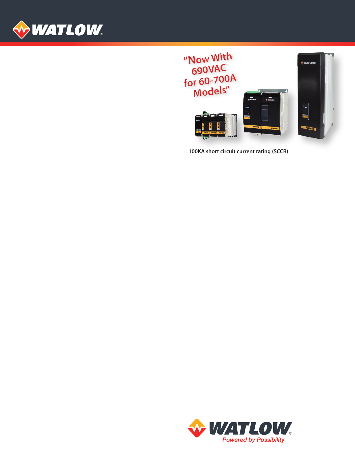
ASPYRE® Power Controllers
Watlow’s new ASPYRE® power controller family is flexible
and scalable, and available with a variety of options allowing
one platform to be re-used across a wide range of applications,
which can help save time and money. ASPYRE models
available include sizes from 35 to 700 amps.
This power controller family features multiple advanced
microprocessor-based firing and control mode algorithms.
Combined with diagnostics and several communications
options the product enables equipment and factory
automation.
Controller firing modes include zero cross, burst firing,
single cycle, delayed triggering and phase angle. These
smart algorithms enable the product to easily control a
wide base of heater loads including nichrome, moly,
silicon carbide, tungsten quartz and infrared lamps and
transformer-coupled loads.
ASPYRE offers a comprehensive list of modular options that
deliver space and labor savings including controlled legs
(1, 2 or 3), semiconductor fusing, load current measurement,
amperage size and user interface.
Features and Benefits
Heater bakeout
• Protects heater on start up
• Eliminates labor and time associated with checking for
wet heaters
Integrated semiconductor fusing, current transformer and
user interface
• Saves installation time and eases setup and commissioning
• Delivers a user-friendly, intuitive interface
Industry-leading design and serviceability
• Offers a robust SCR design to meet a rugged industrial
environment’s high quality and reliability needs
• Provides quick and easy access to maintain and service
fuses and individual legs in minimal time
• Enables fast troubleshooting by providing helpful thermal
system diagnostics
Comprehensive power controller range
• Provides wide range of options from simple single-phase to
complex three-phase loads to 690V
100KA short circuit current rating (SCCR)
• Enables greater protection in the event of a short circuit
c-UL® 508 Listed
• Shortens project schedules, agency testing and expenses
Control modes: contactor, voltage, current or power
• Satisfies a wide range of demanding thermal applications
Load firing modes: zero-cross, burst fire, phase angle, soft
start, half-cycle, single-cycle, delayed triggering
• Handles a wide range of load types including nichrome,
medium and long waveform infrared lamps, moly
(Kanthal® Super), transformers, silicon carbide, UV lamps
and tungsten
• Protects and extends the life of connected loads
Wide range of communication protocols
• Enable factory and process automation with connectivity
access to process and equipment data using Modbus® RTU,
Modbus® TCP, EtherNet/IP™, Wi-Fi, Profibus, Profinet,
USB device (configuration and data file transfers)
Open heater and shorted SCR indication
• Minimizes production downtime with easy to understand,
intelligent, troubleshooting diagnostics
Integrated USB and user interface for configuration
• Easily and safely program configuration settings as the user
interface can be powered through USB connection
• Eliminates a user from having to work in a high voltage
hazard environment. High voltage to controller or
system panel can be turned off while setting controller
configuration
Typical Applications
• Furnace and ovens • Oil and gas
• Autoclaves • HVAC
• Kilns • Textiles
• Heat treatment • Plastics
• Glass industry • Packaging
• Semiconductor • Petrochemical
• Power generation • Dryers and curing
Page 2
Specifications
Power Bases
• Single-phase, 1 controlled leg (2 SCRs)
• Three-phase, 2 controlled legs (4 SCRs)
• Three-phase, 3 controlled legs (6 SCRs)
Load Amp Range
• 35A to 700A @ 40°C ambient
• Amperage derating curve for other ambient temperatures
SCR and Amperage Rating
• Latching current 1A min.
• Power dissipation: approximate 1.25 to 1.5 watts per amp
per controlled leg
• Leakage current: 15mA
• SCCR rating 100,000A up to 600VAC
Line and Load Voltage Range
• 24 to 480V
• 24 to 600V
• 24 to 690V
Voltages -/+ 10% min./max.
690VAC only available for 60A and greater models
• Isolation voltage 2500V
Voltage frequency
• 50 to 60Hz
• Automatically compensates for 47 to 70Hz
Controller Operating Supply Voltage
Nominal Line Voltage (VAC) RMS Max. Operating Range
• 100/120VAC • 90 to 135VAC
• 200/208/220/230/240VAC • 180 to 265VAC
• 277VAC • 249 to 305VAC
•
380/400/415/440/480VAC
•
600VAC
•
690VAC
Control Modes and Load Types
• Voltage, voltage squared, current, current squared, power,
open loop and external
• All control modes available with any ring type
combination
• Normal resistive loads: nichrome, infrared lamps;
medium and long waveform
• Others: Moly (Kanthal® Super), transformers, silicon
carbide, UV lamps, tungsten
Digital Inputs 1 and 2
• ON >=4VDC, OFF <= 1VDC
• 4-30VDC @ 5mA max.
• Digital input functions: enable, change to V feedback, local/
remote set point enable, change ring between phase
angle and default ring mode, ref 1 / 2 selection, log enable,
bakeout enable
• A switched VDC control output can be connected to the
digital input as an open loop control mode command signal
Output Control Firing Types
• Zero crossing
• Single cycle
• Burst ring with delayed triggering, safety ramp and peak
current limit options
• Burst ring with soft start option (phase angle soft start
switching over to burst ring)
• 342 to 528VAC
• 540 to 660VAC
• 621 to 759VAC
Output Control Firing Types (Con’t)
• Phase angle with soft start option
• 1-phase models will include phase angle ring
• 2-phase models are not available with phase angle ring
• 3-phase models from 60 to 500 amps will include phase
angle ring
• 3-phase models from 35 to 40 amp are not available with
phase angle ring
• All models capable of phase angle ring can include
Current Limiting and Heater Bake out functions
• Heater Bakeout and current limit functions require the
Current Limit Loop option
• Current Limit Loop can be ordered as an option in digit
10 of the part number
• If a model does not have phase angle ring it cannot do
Current Limiting, Heater Bakeout, Start Ramp, Safety
Ramp or Delayed Triggering
• Half cycle with start ramp and peak current limit options
Firing Type
Combinations Available
Zero Crossing
Zero Crossing + Start
Ramp
Zero Crossing + Start
Ramp + Soft Start
Zero Crossing + Soft Start X X X
Burst Firing X X X
Burst Firing + Soft Start X X X
Burst Firing + Start Ramp X X
Burst Firing + Start Ramp
+ Soft Start
Single Cycle X
Single Cycle + Soft Start X
Phase Angle X X
Phase Angle + Soft Start X X
Half Cycle X
Half Cycle + Soft Start X
Burst Firing + Delayed
Triggering + Soft Start
Burst Firing + Delayed
Triggering
Burst Firing + Delayed
Triggering + Safety Ramp
Burst Firing + Delayed
Triggering + Safety Ramp
+ Soft Start
Half Cycle + Safety Ramp X
Half Cycle + Safety Ramp
+ Peak Current Limit
1 Phase,
1 Controlled
Leg
X X X
X X
X X
X X
X X
X X
X X
X X
X
3 Phase,
2 Controlled
Legs
Analog Inputs 1 and 2
• Voltage
• 0-10VDC
• 15KΩ impedance
• Current
• 4-20mA, 0-20mADC
• 100Ω impedance
• Potentiometer
• 10KΩ min.
3 Phase,
3 Controlled
Legs
2
Page 3

Analog Output 1
• 0 to 20mA or 4 to 20mA into 500Ω max. load with 50μA
nominal resolution
• 0 to 10VDC into a 500Ω min. load with 50mV nominal
resolution
Analog Output Functions
• Retransmit: Load voltage, current, power or measured input
(Note: If using both Analog Retransmit (digit 10, options A
or D) and Additional Wired Communication (digit 12, options
1-5) an external power supply will be required.
Watlow power supply part number: 0847-0299-0000
Descriptions: AC/DC power supply converter for 90-263VAC to
24VDC, 1.30A, 31W.)
Electromechanical Relay Output
• Form C, 30VDC max. at 1A resistive load or 0.5A at 125VAC,
6000 cycles at 30VDC, 100,000 cycles at 120VAC
Relay Functions
• Alarm output options for heater open break, SCR short or
current limit, heat sink/ambient over-temperature
DC Power Supply for Digital Inputs and Potentiometer
remote set point input
• 10VDC @ 10mA max.
Fusing
• Integrated semiconductor fuse
• Refer to amperage chart for I2T fuse values
Diagnostics Annunciation Messages
• Heater break (open), SCR short circuit (closed), current
limit, thermal switch, SD card error, comms watchdog error,
bakeout in process, aux. voltage too low or high, voltage
line loss
Operator Interface
• 0.96 in. white OLED display with 128 x 64 pixel resolution
• L/R, F UP and DOWN arrow keys
• 4 discrete LED indicators for local/remote mode, enable,
communications and alarm
Connectivity
• EIA 485, Modbus® RTU
• Modbus® TCP Ethernet
• EtherNet/IP™
• Wi-Fi
• USB 2.0 device connection
• PROFIBUS DP
• PROFINET
(Note: If using both Analog Retransmit (digit 10, options A
or D) and Additional Wired Communication (digit 12, options
1-5) an external power supply will be required.
Watlow power supply part number: 0847-0299-0000
Descriptions: AC/DC power supply converter for 90-263VAC to
24VDC, 1.30A, 31W.)
Conguration
• PC software tool and RS485, USB port, or on-board keypad
and LED display
Integrated Data Logging
• Storage: 16 GB SD memory card
• .CSV le type
• User programmable logging intervals 1 to 255 seconds
• Up to 10 parameters selectable by user: line frequency,
output voltage (RMS), output current (RMS), output power
(average), status, commands, set point, current limit
set point (RMS), load resistance, input voltage (RMS)
Real Time Clock and Battery Back-up
• Typical battery life: 5 years at 77°F (25°C)
• CR2032 eld replaceable battery
Cooling mode
• Forced air (fan)
• 24VDC, 120 or 240VAC, 17 watts per fan used
Control Terminals
• Terminals are touch safe, removable, 12 to 22 AWG
Line and Load Terminals
• Compatible with crimp lug terminals or busbar
• Refer to user manual for wire size, compression and torque
requirements
Mounting
• Panel mounting with screws
• Must be mounted with heat sink ns in vertical orientation
Environment
• 0 to 40°C without derating
• 5 to 90% RH (relative humidity), non-condensing
• Up to 2000 meters above sea level max.
• Over 1000 meters of altitude reduce the nominal current by
2% for each 100 meters
• Storage temperature -25 to 70°C max.
Agency Approval and Regulatory
• cULus 508 Listed File E73741
• cUL® Listed to C22.2 No. 14
•
CE EMC Directive 2014-30-EU, EN 60947-4-3 Class A Emissions
• CE Safety Directive 2014-35-EU, EN 60947-4-1, -4-3
• IP20 with all covers in place
• RoHS 2011-65-EU
• W.E.E.E 2012-19-EU
• 690VAC units not covered by UL®
Accessories
• Free Watlow ASPYRE conguration software on the Watlow
website at http://www.watlow.com/en/resources-andsupport/Technical-Library/Software-and-Demos
• 6 ft USB 2.0 to micro USB device cable 0219-0480-0000
• Fuses - see table below
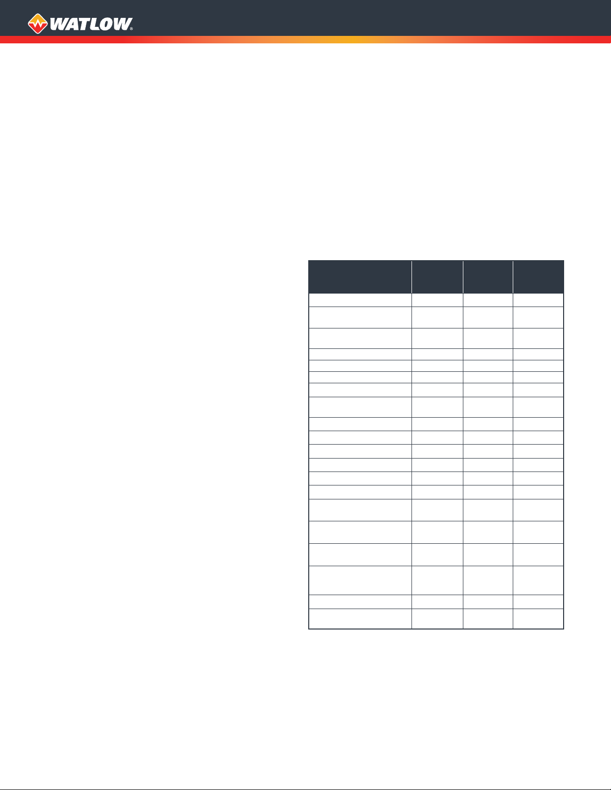
Fuses
ASPYRE
Model
Number
DT_ _ _ - 035 ...
DT_ _ _ - 040 ...
DT_ _ _ - 060 ...
DT_ _ _ - 090 ...
DT_ _ _ - 120 ...
DT_ _ _ - 150 ...
DT_ _ _ - 180 ...
DT_ _ _ - 210 ...
DT1_ _ - 300 ...
DT1_ _ - 400 ...
DT1_ _ - 500 ...
DT1_ _ - 600 ...
DT1_ _ - 700 ...
DT2_ _ - 300 ...
DT2_ _ - 400 ...
DT2_ _ - 450 ...
DT2_ _ - 500 ...
DT2_ _ - 600 ...
DT2_ _ - 700 ...
DT3_ _ - 300 ...
DT3_ _ - 350 ...
DT3_ _ - 400 ...
DT3_ _ - 450 ...
DT3_ _ - 500 ...
* One fuse per switched leg.
Qty.
Used
Per
Unit
1 to 3*
1 0808-0362-0000
1 0808-0358-0000
1 0808-0359-0000
4
4
3 0808-0357-0000 2055-5072
3 0808-0358-0000 0808-0358-0000
6
6
4
4
3 2055-5072
3
3
3
3
Watlow Fuse Part Number
480V and 600V 690V
17-8050
0808-0363-0160
0808-0363-0180
0808-0363-0200 2048-4405
0808-0363-0250 2048-4418
0808-0363-0315 2048-4426
0808-0363-0250 0808-0363-0250
0808-0360-0000 0808-0360-0000
0808-0357-0000
0808-0358-0000 0808-0358-0000
0808-0359-0000 0808-0359-0000
2048-2760
0808-0362-0000
0808-0358-0000
0808-0359-0000
0808-0357-0000
3
Page 4

I/O Functional Block Diagram
Profibus DP
Backup Power
•
User Interface
•
Communications
DC Power
Supply
•
Dry Contact
Switches
•
Potentiometers
Analog
Retransmit
•
User-Selectable
Retransmit Parameter
•
0 to 20mA or
4 to 20mA
•
0 to 10VDC
USB Device
•
Configuration
Software Connection
•
Data Log File Transfer
Wi-Fi
•
Configuration
•
Monitor Operation
Power Switching
•
1, 2 or 3 Legs
•
Back-to-Back SCR Switching
•
Replaceable Semiconductor Fuses
Analog
Input
2 Analog Inputs
•
Set Point
•
Feedback
•
Current Limit
2 Digital Inputs
•
Enable
•
Select Feedback
•
Local/Remote
•
Set Firing Type
Auxiliary Power
•
Controller
Electronics
•
Voltage Sensing
•
Zero-Cross Sensing
Analog
Input
Auxiliary
Power
* Current Limit
1-phase and 3-phase, 3-leg models only.
Not available on 35 amp and 40 amp, 3-phase 3-leg models.
(Optional)
+24VDC
Input
Voltage
Sensing
+10VDC
Output
Fan Power
Input
Fan Power
•
24VDC
•
120 or 240VAC
(Optional)
Analog
Retransmit
NCNO
Mechanical
Relay Output
•
Alarm Annunciation
(Optional)
Data
Logging
RS-485
Interface
•
Modbus TCP
•
2nd Modbus RTU (485)
•
(Optional)
Power
Demand
Loop
(Optional)
Current
Limit
Loop*
Current
Sensing
(Optional)
•
Profinet
•
EtherNet/IP™
(Optional)
(Optional)
Out to LoadIndustrial Communications
4
Page 5

Dimensions and Shipping Weight
Current and Voltages
35 and 40A
480 and 600VAC
1 Controlled Leg
1-Phase,
3-Phase,
2 Controlled Legs
3-Phase,
3 Controlled Legs
60, 90, 120, 150,
180 and 210A
480 and 600VAC
60, 90, 120, 150,
180 and 210A
690VAC
4.77 in. H x 2.84 in. W x
7.28 in. D - 2.6 lbs
10.6 in. (60A) or 10.79 in.
(90-210A) H x 3.66 in. W x
6.7 in. D - 9 lbs
4.77 in. H x 4.25 in. W x
7.28 in. D - 4 lbs
10.6 in. (60A) or 10.79 in.
(90-210A) H x 7.36 in. W x
6.7 in. D - 18 lbs
4.77 in. H x 5.67 in. W x
7.28 in. D - 5.5 lbs
10.6 in. (60A) or 10.79 in.
(90-210A) H x 11.1 in. W x
6.7 in. D - 27 lbs
1 and 2 leg:
300, 400, 500, 600 and 700A
3 leg:
300, 350, 400, 450 and 500A
480, 600 and 690VAC
17.33 in. H x 5.40 in. W x
10.63 in. D - 23 lbs
20.47 in. H x 5.4 in. W x
10.63 in. D - 33 lbs 20.47 in. H x 10.32 in. W x 10.63 in. D - 63 lbs
60-90A = 17.33 in. H x 5.40 in. W x 10.63 in. D - 23 lbs
120-210A = 17.33 in H x 10.32 in. W x 10.63 in. D - 40 lbs
5
Page 6

Ordering Information
Base model includes: power control loop for open loop, voltage, current or power control, two analog inputs (0-10VDC, 4-20mA selectable),
two digital inputs, semiconductor fusing and current transformers for each leg, mechanical relay heater break alarm, RS-485 Modbus®
communications, pixel OLED user interface and keypad, 10VDC auxiliary power supply
Part Number
① ②
③
④ ⑤
Max. Line
⑥ ⑦ ⑧
& Load
Model
Phase
Voltage
DT
③
1 =
1-phase, 1 controlled leg
2 =
3-phase, 2 controlled leg
3 =
3-phase, 3 controlled leg
④ ⑤
48 =
480VAC
60 =
600VAC
69 =
690VAC - Only available for 60A and greater models
⑧
⑥ ⑦
035 =
35A
040 =
40A
060 =
60A
090 =
90A
120 =
120A
150 =
150A
180 =
180A
210 =
210A
300 =
300A
350 =
350A - Not available for 1-phase, 1 leg or 3-phase, 2 leg models
400 =
400A
450 =
450A - Not available for 1-phase, 1 leg models
500 =
500A
600 =
600A - Not available for 3-phase, 3 controlled leg models
700 =
700A - Not available for 3-phase, 3 controlled leg models
⑨
1 =
100 or 120VAC 90-135V
2 =
200, 208, 220, 230 or 240VAC 180-265V
3 =
277VAC 249-305V
4 =
380, 400, 415, 440 or 480VAC 342-528V
5 =
600VAC 540-660V
6 =
690VAC* 621-759V
* 690VAC only available for 60A and greater models.
Watlow® and ASPYRE® are registered trademarks of Watlow Electric Manufacturing
Company.
Modbus® is a registered trademark of Schneider Automation Incorporated.
UL® and c-UL® are registered trademarks of Underwriter’s Laboratories, Inc.
Kanthal® Super is a registered trademark of Bulten-Kanthal Aktiebolag Joint Stock
Company.
EtherNet/IP™ is a trademark of Open DeviceNet Vendors Association.
Maximum Line and Load Voltage
Nominal Voltage Supplied to SCR
Nominal Maximum Operating Range
Amperage
–
Phase
Amperage
⑨
Nominal Voltage
Supplied to SCR
⑩
Additional
Options
⑪
Cooling
Fan
Voltage
⑫
Add’l Wired
Comms.
⑬
Wireless
Comm. &
Data Logging
Firmware Overlay, Preset
Parameters and Locked Code
–
⑩
A =
B =
C =
D =
Note 1: Current limit loop only available with 1-phase and 3-phase, 3-leg
models (DT1 and DT3). Exception: Current limit not available with the 35A
and 40A, 3-phase, 3-leg models (DT3xx-035xx-xxxxx and DT3xx-040xx-xxxxx).
Note 2: If using both Analog Retransmit (digit 10, options A or D) and
Additional Wired Communication (digit 12, options 1-5) an external power
supply will be required. Watlow power supply part number: 0847-0299-0000
Descriptions: AC/DC power supply converter for 90-263VAC to 24VDC, 1.30A,
31W.
Current Limit Loop
⑪
0 =
No fan - option only valid for models ≤60A
1 =
120VAC*
2 =
240VAC*
3 =
24VDC*
* Fan voltage required on models ≥90A, not valid option for
models ≤60A.
⑫
0 =
1 =
2 =
3 =
4 =
5 =
Note 1: All additional communication options include auxiliary 24VDC
backup power supply for communications.
Note 2: If using both Analog Retransmit (digit 10, options A or D) and
Additional Wired Communication (digit 12, options 1-5) an external power
supply will be required. Watlow power supply part number: 0847-0299-0000
Descriptions: AC/DC power supply converter for 90-263VAC to 24VDC, 1.30A,
31W.
⑬
2
Additional Wired Communication (Modbus® RTU-485
No Add’l
Comms.
Modbus®
TCP
X
Wireless Communications & Data Logging
Wi-Fi
A =
B =
C =
D =
*
40A and lower models do not include battery back-up or real
time clock.
⑭ ⑮
AA =
AB =
RC =
XX =
Custom Options - Firmware Overlay, Preset Parameters and
Standard with user manual documentation
Standard without user manual documentation
Replacement connector hardware only - for configuration entered
above
Contact factory - custom firmware, preset parameters, locked code
Additional Options
Yes Yes
No No
Yes No
No Yes
Cooling Fan Voltage
Comes Standard in all Models)
X
X
X X
nd
2
Modbus®
RTU 485
X
Locked Code
Analog Retransmit Output 1
Profibus
DP
X
*Data Logging With Battery
Back-Up and Real Time Clock
⑭ ⑮
Custom Options -
Profinet EtherNet/IP™
X
X
X
Powered by Possibility
To be automatically connected to the nearest
North American Technical Sales Oce:
1-800-WATLOW2 • www.watlow.com
inquiry@watlow.com
©2019 Watlow Electric Manufacturing Company all rights reserved.
6
International Technical Sales Offices:
Austria +43 6244 20129 0
China +86 21 3532 8532
France +33 1 41 32 79 70
Germany +49 7253 9400 0
India +91 40 6661 2700
Italy +39 02 458 8841
Japan +81 3 3518 6630
Korea +82 2 2169 2600
Mexico +52 442 256 2200
Singapore +65 6773 9488
Spain +34 91 675 1292
Taiwan +886 7 288 5168
UK +44 115 964 0777
WIN-ASP-0419
 Loading...