

Page 1

ANASCAN
User’s Guide
Watlow Controls
1241 Bundy Blvd.
Winona, MN 55987
Customer Service
Phone: (800) 414-4299
Fax: (800) 445-8992
Technical Support
Phone: (507) 494-5656
Fax: (507) 452-4507
Email: wintechsupport@watlow.com
Part No. 10852-10. Revision 2.1
July 1997
Page 2

Copyright © 1997
Watlow Anafaze
Information in this manual is subject to change without notice. No part of this publication may be
reproduced, stored in a retrieval system, or transmitted in any form without written permission
from Watlow Anafaze.
Warranty
Watlow Anafaze, Incorporated warrants that the products furnished under this Agreement will be
free from defects in material and workmanship for a period of three years from the date of shipment. The customer shall provide notice of any defect to Watlow Anafaze within one week after the
Customer's discovery of such defect. The sole obligation and liability of Watlow Anafaze under this
warranty shall be to repair or replace, at its option and without cost to the Customer, the defective
product or part.
Upon request by Watlow Anafaze, Incorporated, the product or part claimed to be defective shall
immediately be returned at the Customer's expense to Watlow Anafaze. Replaced or repaired products or parts will be shipped to the Customer at the expense of Watlow Anafaze.
There shall be no warranty or liability for any products or parts that have been subject to misuse,
accident, negligence, failure of electric power or modification by the Customer without the written
approval of Watlow Anafaze. Final determination of warranty eligibility shall be made by Watlow
Anafaze. If a warranty claim is considered invalid for any reason, the Customer will be charged for
services performed and expenses incurred by Watlow Anafaze in handling and shipping the
returned unit.
If replacement parts are supplied or repairs made during the original warranty period, the warranty
period for the replacement or repaired part shall terminate with the termination of the warranty
period of the original product or part.
The foregoing warranty constitutes the sole liability of Watlow Anafaze and the customer's sole
remedy with respect to the products. It is in lieu of all other warranties, liabilities, and remedies.
Except as thus provided, Watlow Anafaze disclaims all warranties, express or implied, including
any warranty of merchantability or fitness for a particular purpose.
Please Note: External safety devices must be used with this equipment.
Page 3

Contents
INTRODUCTION 1
ANASCAN Features .......................................................1
Computer Requirements .................................................2
INSTALLATION 5
Quick Installation ............................................................5
ANASCAN Files ............................................................5
File Locations .................................................................6
Installation Program ........................................................7
Installation Menu ............................................................8
Directory Paths ...............................................................8
Grouping Channels .........................................................9
START UP 11
Quick Start Up ................................................................11
Start Up Optional Modes ................................................11
Start Up Sequence ...........................................................12
Default Start Up Values ..................................................13
Start Up Errors ................................................................14
GENERAL SCREEN
DISPLAYS 19
Changing Data ................................................................20
Print Screen .....................................................................20
CHANNEL OVERVIEW 21
Getting Here ....................................................................21
Options ............................................................................21
Function Keys .................................................................23
EDIT 25
Getting Here ....................................................................25
Function Keys .................................................................25
CHANNEL SETUP 27
Getting Here ....................................................................27
Function Keys .................................................................28
Parameters .......................................................................28
ANASCAN User’s Guide i
Page 4

SYSTEM SETUP 33
Getting Here ....................................................................33
System Errors ..................................................................34
System Software .............................................................35
Passwords ........................................................................35
System Parameters ..........................................................36
System Terminate ...........................................................37
System Start Up ..............................................................38
Data Logging ..................................................................40
Controller Comm. ...........................................................41
Digital Output Polarity ....................................................42
JOB SETUP 43
Getting Here ....................................................................43
Function Keys .................................................................44
VIEW ALARMS 45
Getting Here ....................................................................45
Function Keys .................................................................46
Alarm Screen Auto Switch .............................................46
Audible Alarm ................................................................46
TREND PLOT 47
Getting Here ....................................................................47
Function Keys .................................................................48
Trend Plot Setup Screen .................................................48
Getting Here ....................................................................48
Print Trend Plot Screen ...................................................50
APPENDIX: Input Scaling 51
Linear Input Scaling ........................................................51
ii ANASCAN User’s Guide
Page 5

Overview
Using This Guide
This manual describes how to install, setup, and operate ANASCAN.
ANASCAN is a DOS-based software program that allows you to
program and monitor multiple CAS and CAS200 scanners from a single
PC. Hereafter, both the CAS and CAS200 scanners are referred to as
CAS scanners.
This guide is intended for both experienced and inexperienced users.
Experienced users may find some parts of this guide very simplistic; if
that’s you, please at least skim these parts to make sure you don’t miss
anything vital. If you’re an inexperienced user, please read this guide
carefully.
The following describes each section.
•
Introduction: Describes ANASCAN and its computer require-
ments.
•
Installation: Covers how to install and setup ANASCAN.
•
Startup: Describes program loading and startup errors.
•
General Screen Displays: Provides an overview of the screen and
typical screen responses.
•
Channel Overview: Describes the channel overview screen.
•
Edit: Describes the edit screen.
•
Channel Setup: Gives an overview of the channel setup screen.
Included are descriptions of system parameters.
•
System Setup: Describes the system setup screen.
•
Job Setup: Describes the job setup screen.
•
View Alarms: Describes alarms and how to view them.
•
Trend Plot: Covers trend plotting and reviewing trend plots.
•
Appendix: Describes input scaling examples.
ANASCAN User’s Guide iii
Page 6
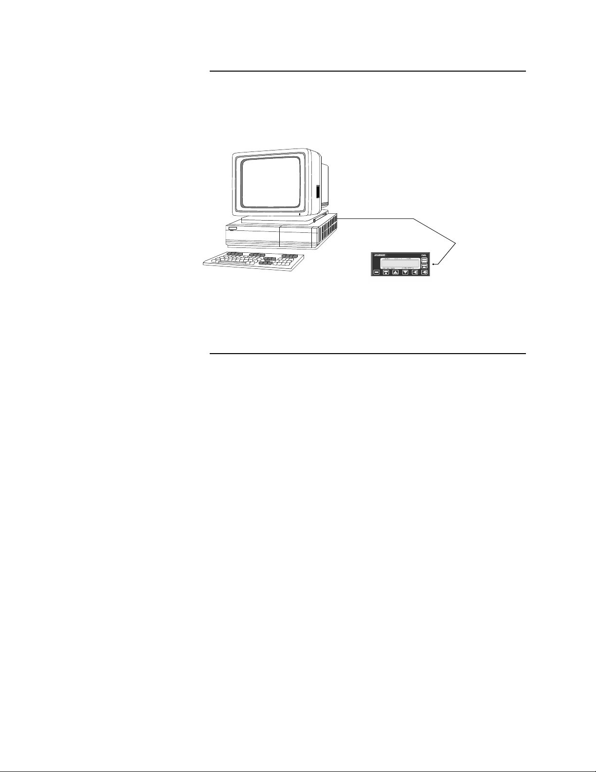
System Block Diagram
The following shows how the PC interface (with ANASCAN) to several
units.
Communications
Cable (serial port 1 or 2)
1 or more CAS units
Parts List
The following parts are included with ANASCAN.
•
ANASCAN on 3.5 inch Diskette. (5.25 in diskettes are available
upon request)
•
RS-232 or RS-485 communications cable
iv ANASCAN User’s Guide
Page 7

Safety
Watlow Anafaze has made efforts to ensure the reliability and safety of
ANASCAN. Note that in any application failures can occur.
Good engineering practices, electrical codes, and insurance regulations
require that you use independent external safety devices to prevent
potentially dangerous or unsafe conditions. Assume that ANASCAN
can fail or that other unexpected conditions can occur.
For additional process safety, program a computer or other host device
to automatically reload your desired operating parameters after a power
failure. However, this safety feature does not eliminate the need for
other external, independent safety devices in dangerous conditions.
In the event of a CAS reset, ANASCAN will reload the unit with the
current values in computer memory. The user must ensure that this reset
will be safe for the process. Use of ANASCAN does not eliminate the
need for appropriate external, independent safety devices.
Please contact Watlow Anafaze immediately if you have questions
about system safety.
ANASCAN User’s Guide v
Page 8

vi ANASCAN User’s Guide
Page 9

INTRODUCTION
ANASCAN is a user friendly, menu driven software package. It
interfaces the Compact Alarm Scanner (CAS) system to monitor inputs
and alarms for up to 16 independent channels.
You may have only one CAS or a plant wide system with numerous
units. ANASCAN includes numeric and graphic displays, data and
alarm printing, data and alarm logging in text or LOTUS compatible
files, and graphic trending. It runs on an IBM AT 286, 386, or 486, and
true compatible computers. A question and answer format enables
users to quickly define and setup any measurement or application.
NOTE
ANASCAN is sold with a license agreement and can be operated
only on one computer. The license agreement requires registration
with Watlow Anafaze. Watlow Anafaze will send updates at no
charge only to registered users. See registration form at the end of
this manual.
INTRODUCTION
ANASCAN Features
ANASCAN provides these features:
•
Process overview screens
•
Channel setup screen, individual channel parameters editing
•
Maintaining a directory of job files
•
Displaying and logging process variable alarms
•
Password protection for various levels of program
•
Software grouping of Channels
•
Graphic trend plotting of process variabilities points and output val-
ues in real time
•
Definable startup sequences
•
Power failure recovery
•
Printer and disk data and alarm logging
ANASCAN User’s Guide 1
Page 10

INTRODUCTION
Computer Requirements
Watlow Anafaze sets these computer requirements for running
ANASCAN:
1. IBM AT 286, 386, 486 or other IBM Compatible Computer
2. DOS Version 3.3 or higher
3. Speed: 25 MHz or higher
This speed provides the best performance of the ANASCAN program; it enhances the response of the system to changes and maintains the best screen updates. However, it is not a factor in the
performance of the system since this is maintained independently in
each Watlow Anafaze controller.
4. Memory: 580K bytes free memory or larger
5. Disk Drives: One 40MB hard disk. One 5.25” and/or 3.5” floppy disk
6. Graphics Interface: EGA/VGA
7. RS-232 or RS-485 Serial Interface
The serial communication link required to communicate with more
than one CAS or with a communication cable longer than 50 feet is
RS-485. Watlow Anafaze recommends using the standard serial
interface of RS-232 with an external RS-485 converter.
A converter recommended by Watlow Anafaze is the B&B Electronics RS-232/RS-485 optically isolated converter P/N 485OIC. This
converter has screw terminals for connecting the RS-485 wires and
the DB-25 Male connector for the RS-232 side.
Other recommendations are the Black Box RS-232/RS-485 non-isolated converter P/N ME-836A. The ME-836A connections are the
same except the terminals are labeled with an X instead of a D. The
converter is used for both 2-wire/4-wire systems.
To provide optical isolation, the addition of Black Box opto-isolator
P/N SP400A is highly recommended. The SP400A will normally use
the factory DIP switch settings. All that needs to be done is to connect the cable and the power supply. The SP400A has been used
without any power supplies required as it will draw its power from
the computer and the ME-836A. Always use equipment manufacture
factory recommendations.
To use a PC internal mounted RS-485 card, the Black Box Corp. P/N
IC030 has been used successfully in Watlow Anafaze installations.
Caution must be taken when other communication devices are
installed so as not to conflict with the address or interrupt.
Another PC internal optically isolated RS-485 serial card is BB Electronics model # 3PX0CC1A.
2 ANASCAN User’s Guide
Page 11

INTRODUCTION
8. Printer Parallel Interface
The printer parallel interface port is required for the Watlow Anafaze
software key. The Watlow Anafaze software key must be installed on
the printer port. System operation of the CAS is not possible without
the software key. [See Software key installation].
9. Battery backed up real time clock (usually battery backed CMOS
chip)
10. EGA/VGA Monitor
The EGA interface card will allow color trend plotting even with a
CGA monitor. The EGA/VGA monitor used with the EGA/VGA
interface provides improved text displays making all the screens easier to read. For systems that require frequent operator changes and
frequent observation, full EGA or VGA is recommended.
11. IBM Graphics Compatible Printer
This graphics printer is required for printing data and alarm logging
features of ANASCAN.
ANASCAN User’s Guide 3
Page 12

4 ANASCAN User’s Guide
Page 13

INSTALLATION
Quick Installation
•
Create a directory on your hard disk and change to that directory.
•
Type A:\ANASCAN2. The file will self-extract into the directory.
•
Type SCANINST from your ANASCAN directory (If you copied the
file to the hard disk. If you didn’t, type the appropriate drive).
•
Press Enter. Installation menu appears.
•
Change inputs in the installation menu by moving the cursor to the
desired parameters.
•
You are ready for start up.
INSTALLATION
ANASCAN Files
WARNING
It is your responsibility to ensure that the entire system is safe.
Read the warning in the front of this manual. If there is any
possibility of an unsafe condition, use independent safety
devices.
ANASCAN2.EXE - a self extracting program that contains the program
files.
SCANINST.EXE - ANASCAN installation program
ANASCAN.EXE - a file that contains the main program software.
Support files:
INSTAL.DAT - installation parameters data file
LPGRP.DAT - channel grouping start up data file
SYSSU.DAT - system setup data file
STATUS.DAT - system start up status file
DIGIO.DAT - digital I/O screen data
DLOG.DAT - data logging data file
GRPINFO.DAT - group set up data file
HDR.WK1 - Lotus header set up file
ANASCAN User’s Guide 5
Page 14

INSTALLATION
PLOT.DAT - plot parameters data file
Files created by ANASCAN:
XXXXXXXX.J## - group job directory data file
NEWXX.PLT - plot files which were created within the last 24 hours.
OLDXX.PLT - older plot files
PXXXXXXX.TXT or WK1 process logging files
AXXXXXXX.TXT or WK1 alarm logging files
WARNING
Make copies of disks before running the program, and store the
original ANASCAN disks in a safe place. Use the copies to operate the system.
File Locations
360k dual floppy disk system:
Watlow Anafaze recommends that you store the ANASCAN operating
program file and the INSTAL.DAT file on drive A, and all other files on
drive B. Once the program SCANINST is run, you can remove
SCANINST.EXE from drive B to allow more room for data. Do not
remove files from the master disk. This recommendation ensures that
the autoboot feature will bring up the program automatically in the
occurance of a power outage.
720k or higher floppy disk system:
Watlow Anafaze recommends that you store all files of the ANASCAN
operating program on one drive such as A. Use the B drive to store all
recording data by setting up directories as shown in the hard disk system
recommendations.
Hard disk systems:
Watlow Anafaze recommends setting up directories as follows:
ANASCAN - to contain the operating program, system data and job
files
6 ANASCAN User’s Guide
DATALOG - to contain data logging files generated by ANASCAN
ALARMLOG - to contain alarm logging files generated by ANASCAN
Page 15

Installation Program
INSTALLATION
For easy removal of recorded data, you may install the DATALOG and
ALARMLOG directories on the A or B floppy drives. For automatic
reboot use the B drive recording data to the floppy.
Copy all the supplied files to the ANASCAN directory.
The installation program, SCANINST.EXE, customizes each
ANASCAN program for the application. When typing C:SCANINST
(if it’s on the hard disk), or B:SCANINST (if it’s on drive B), The
installation screen appears and enables you to select parameters used by
ANASCAN.
SCANINST.EXE stores the program setup parameters in a file called
INSTAL.DAT. When run, the SCANINST program reads the
INSTAL.DAT file from the default disk directory. If both files are on
the same disk directory, enter the directory and type SCANINST.
If the SCANINST.EXE and INSTAL.DAT file are on different
directories, enter the disk directory containing INSTAL.DAT and type
SCANINST preceded by the path to the disk directory containing
SCANINST. For example, if INSTAL.DAT is on drive A and
SCANINST.EXE on drive B, type :
B:>A: [Enter] to change the current default drive to A
A:>B:SCANINST [Enter] to start the installation program
If the installation program cannot find INSTAL.DAT, an error message
appears. Verify the location of INSTAL.DAT file.
ANASCAN User’s Guide 7
Page 16

INSTALLATION
Installation Menu
1 to 16 This value is fixed
for the CAS
Total number of
channels (this
will vary due to
the number of
CAS systems
installed)
Selects the Group Edit Screen.
See Grouping channels in this
section.
Select 9600 or
2400 Baud.
Set to either BCC (Block Check
Character) or CRC (Cyclic
Redundancy Check). Use BCC
for standard applications. CRC
ensures a higher degree of security but decreases the overall
cummunication rate. Use CRC
only when you anticipate severe
communication noise.
The PC’s serial communications
port to the controller (can only
be 1 or 2)
For these paths,
refer to the next
page
Directory Paths
8 ANASCAN User’s Guide
Number of channels
ANASCAN displays 16 channels with system numbers. The system
channel numbers associated with the CAS channels are indicated in the
installation program as the Begin Channel and End Channel for each
scanner. A 17th channel is reserved for pulse monitoring.
Job/Parameters path
This is the path to the disk directory containing the Job and System
Parameters Data Files. The path would normally be:
B:\ANASCAN\ or .\ current directory (If the system files are on drive
B)
Page 17

INSTALLATION
C:\ANASCAN\ or .\ current directory (If the system files are on the
hard disk). Notice that the last “\” is added automatically.
Data logging path
This is the path to the disk directory containing the LOTUS or text
[ASCII] data logging files generated by ANASCAN. This directory
must exist before running ANASCAN and turning on data logging.
B:\ANASCAN\DATALOG\ (for floppy disks)
C:\ANASCAN\DATALOG\ or.\DATALOG\ (for hard disks). Notice
that the last “\” is added automatically.
Alarm logging path
This is the path to the disk directory containing the LOTUS or Text
(ASCII) alarm record files generated by ANASCAN. This directory
must exist before running ANASCAN and turning On alarm logging.
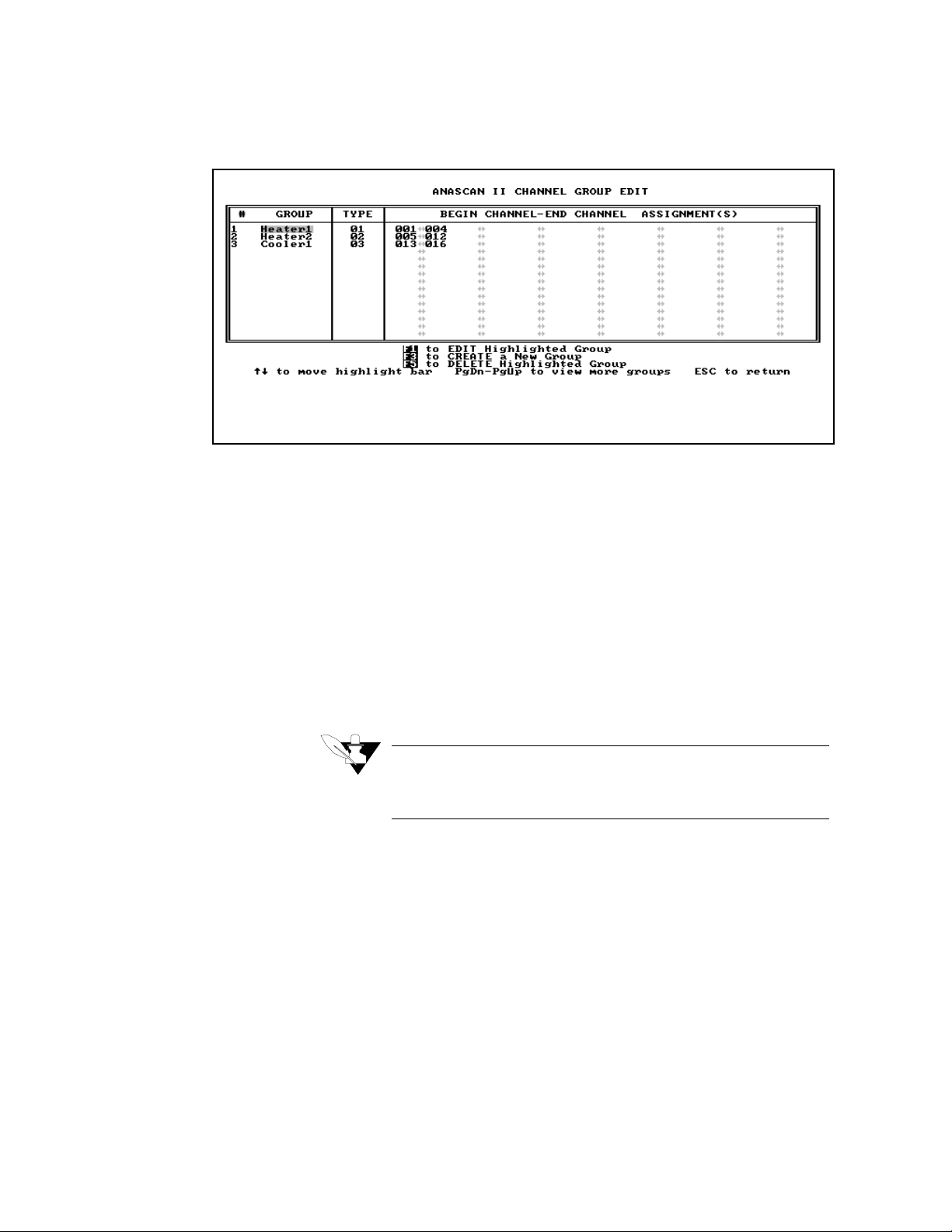
Grouping Channels
B:\ANASCAN\ALARMLOG\ (for floppy disks)
C:\ANASCAN\ALARMLOG\ or .\ALARMLOG\ (for hard disks).
Notice that the last “\” is added automatically.
Grouping inputs allows you to divide your system into subsystems. You
can group channels with a common purpose according to your specific
application requirements. One group might be for a furnace or a group
of furnaces; another group might be for common Jobs shared between
devices.
Only the channels of one group are displayed on the Overview screen at
a time. The job parameters are uploaded or downloaded to an individual
group independently. The number of controllers with their total number
of channels must match the number of channels in the grouping. The
channel numbering depends upon the type of input selected in the
SCANINST program.
After assigning the channel numbers to a group, select a type number of
two digits up to 99. This number is the job directory number for the
group and its channels. All groups with the same type number will be
assigned to the same job directory. Creating a new type number creates
a new job directory number in the ANASCAN program.
ANASCAN User’s Guide 9
Page 18
INSTALLATION
Group menu
General grouping rules
•
Create a group when you need to have the channels on the same
Overview screen.
•
Assign the channels to the group you want to have on the same
Overview screen.
•
Create a type number for the new group. This type number can be
assigned to more than one group if they share common jobs through
the ANASCAN.EXE program. However, when using the same
type number for groups, the number of channels must match.
Otherwise a new type number must be used.
NOTE
Type value is used to store jobs specific for that type. The Default
job is only stored under type 01.
10 ANASCAN User’s Guide
Page 19

START UP
Quick Start Up
•
Ensure time and date are correct in your computer.
•
Type: ANASCAN. Job Select screen appears.
•
Type a job’s name. When starting the first time, enter DEFAULT.
•
Type D for downloading parameters to the CAS, or U for uploading. For
initial testing in the Edit mode, enter D.
•
Overview screen appears.
Start Up Optional Modes
You can start ANASCAN in certain modes by adding parameters to the
command at start up. These command line options include:
•
/e
Operates the program in Edit mode. The program operates normally
but it does not communicate with the CAS. You can operate the
program in Edit mode without any hardware connected to the computer. This mode is useful for initial familiarization, training, and
Off Line job editing.
•
/c
Forces the graphics display into CGA mode. This is necessary on
some computers which are not truly IBM compatible.
•
/d
Operates the program in the Debug mode. This is useful in debugging communications problems. Don’t use it for normal operations. All communications between the computer and the CAS are
displayed on the printer. Therefore, in order to use this mode, the
printer must be connected and ready.
You can use capital or small letters in the command line, and more than
one command line option at a time. For example:
Typing ANASCAN /E /C [enter] will operate the program in Edit mode
with CGA graphics.
ANASCAN User’s Guide 11
Page 20

START UP
Start Up Sequence
•
The program checks the computer system hardware and the access
to the system disk files.
•
The program verifies communications to each CAS in the system
and their versions.
•
Job Directory screen appears.
•
The program prompts for the job to run. ANASCAN program is
supplied with a job named DEFAULT which contains all the
default parameters and setups. When starting the first time, enter
the job name DEFAULT.
WARNING
When the CAS is monitoring, upload to install parameters into
the ANASCAN operating program. Downloading will install
factory default values. For Initial testing in the Edit mode,
enter Download.
•
After the downloading sequence is complete, the program displays
the Overview screen. If there is a problem in the program start up,
see start up errors in this section.
12 ANASCAN User’s Guide
Page 21

Default Start Up Values
START UP
The program is shipped to you containing several parameters which are
set to initial factory default values. These should be set to desired values
by supervisory personal, and they include:
•
Passwords
•
Program startup sequences
•
Data logging parameters
•
Trend plotting parameters
See System Setup for detailed information.
ANASCAN User’s Guide 13
Page 22

START UP
Start Up Errors
During Start up, various error messages may appear. The following
tables describe these messages, their causes and solutions.
Memory allocation errors
ANASCAN allocates computer memory for the channel parameters,
based on the number of channels and options in the system. When
ANASCAN reads in the system data files and finds there isn’t sufficient
memory, these messages may appear:
Message Cause Solution
Insufficient
Memory
MEM ERROR:
Alarm Queue
Trend Logging
Disabled
Not enough memory to allocate
data arrays required to run the program. The program cannot run and
it terminates.
Not enough memory to allocate the
alarm log memory. The program
operates, but the view alarms
screen doesn’t display alarm queue.
Not enough memory to allocate
some or all of the trend logging
memory queues. The program
operates normally, but the trend
plotting is not available.
•
Check the memory by
running the DOS command CHKDSK. At least
580K should be free.
•
Make sure your computer
has 640K memory, and
remove any memory resident programs and drivers. Check
AUTOEXEC.BAT file to
see if it runs any memory
resident programs. After
removing these programs,
re-boot the computer.
Same as above.
Same as above.
14 ANASCAN User’s Guide
Page 23

Disk file errors
While reading in the system files, several reading errors can occur. The
system files are SYSSU.DAT, INSTAL.DAT, and PLOT.DAT.
ANASCAN cannot run without these files.
Message Cause Solution
ERROR WHILE
READING DATA
FILE: xxxxxxxI
FILE NOT FOUND
ERROR WHILE
READING DATA
FILE:xxxxxxx
Drive not ready
Read fault
General failure
or
Access failure
ERROR WHILE
READING DATA
FILE:xxxxxxx
Path not valid
or
Invalid disk drive
INVALID DATA
FOUND ON DATA
FILE:xxxxxxx
The system file does
not exist on the indicated disk and directory path.
There is a disk drive
hardware access failure.
The data disk path
that you set in the
SCANINST installation program is not
valid.
There is corrupted or
invalid data in the
disk file.
The INSTAL.DAT file should be on the
default drive and directory. The other system files should be on the data file drive
and directory path as set in the installation
program. If these files are not in the right
directories, copy the system files from the
backup disks to the appropriate directories.
Run CHKDSK or other diagnostic program in order to verify that there is no disk
drive error.
For a floppy drive: make sure that there is
a disk in the right drive and that the drive
door is closed.
Run SCANINST and verify that the drive
and directory path exist and are valid.
Don’t forget to verify that “\” is at the end
of the path entry.
Copy the original data file sent with
ANASCAN from the backup disks.
START UP
ANASCAN User’s Guide 15
Page 24

START UP
Extended start up sequence errors
ANASCAN reads in the status file STATUS.DAT which contains
information saved by ANASCAN the last time it was running. Several
errors can occur when reading this file.
Message Cause
Could not find
STATUS.DAT
start up file
Invalid data
value on STATUS.DAT start
up file
Power Failure
Recovery
System clock
Error
The file could
not be found
on the data file
disk directory
set by SCANINST. The file
may have been
erased or corrupted.
The file contains some
invalid data,
and
ANASCAN
assumes that
the file was
corrupted.
The current
system time/
date as saved
in the STATUS.DAT file
were not in a
valid range.
The computer
system clock
is not set to
valid time and
date.
Program
Action
ANASCAN continues with the
start up, but since
there is no power
failure information available,
ANASCAN
assumes the Over
Power Failure
Recovery time
Limit action and
starts in that mode.
Same as above. Same as above
Same as above. The automatic power failure
As the program is running, the
STATUS.DAT file will be
established. Therefore, subsequent starts should have no
problem.
recovery feature of
ANASCAN requires a correct clock/calendar system.
While the computer boots up,
verify the following:
•
•
•
Solution
There is a battery backed
up clock/calendar in the
system.
The battery is good.
Time and date values are
correctly loaded.
16 ANASCAN User’s Guide
Page 25

Communications problems
Message Cause Solution
Failed Communications to CAS
Abort start up
(Y/N):
ANASCAN cannot communicate with one of the
CAS during the initial system communications
check or during the job
downloading/uploading.
•
Verify that the communications
port set in ANAINSTL is the one
actually connected to the CAS.
•
Verify that the communications
parameters (baud rate and error
checking mode) set in the installation program are those set in
the CAS. The CAS communications parameters are set using the
front panel keys while in the
GLOBAL menu.
•
Verify that the address of each
CAS is unique (for multiple CAS
systems).
•
Verify that the correct version of
ANASCAN is running for the
CAS being used.
•
Verify that the wiring is done
correctly to the CAS and the
computer.
START UP
NOTE
See the respective CAS hardware manual for assistance in checking
the communication parameters and verifying the communication
wiring.
•
If there is more than one CAS in the system, ANASCAN will try
supervising those CAS which are operating and communicating
correctly. After start up ANASCAN periodically re-checks communications to the failed CAS.
•
By continuing the start up, the CAS not communicating will be
listed by address on the System Errors window in the System Setup
screen. Check the unit listed on the screen. Be sure the address is
correct as set on the CAS.
ANASCAN User’s Guide 17
Page 26

START UP
EPROM version error
ANASCAN checks the CAS EPROM version at start up and verifies
that it’s acceptable to the version of ANASCAN. The following
message may appear:
Message Cause Solution
Unacceptable
CAS EPROM
version
The EPROM version is
not acceptable to the
version of ANASCAN.
.
Contact Watlow Anafaze to obtain EPROM
upgrade
18 ANASCAN User’s Guide
Page 27

GENERAL SCREEN
DISPLAYS
Certain characteristics are maintained on all ANASCAN screens as
follows:
Title line. Includes screen’s name, current channel and job, and the time and
date. When in Edit mode, "Edit Mode" will appear at this location.
Process status box. Four possible
messages:
1. Process OK (green).
2. Process warning (yellow).
there is a warning on at least one
channel.
3. Process alarm (blinking red). An
alarm condition on at least one
channel has not been acknowledged.
4. Process alarm (red). An alarm
condition on at least one channel. All
alarms have been acknowledged.
System status box. Reports problems
of communications, printer access,
or data logging disk access. Two
possible messages:
1. System OK
2. In case of a problem, the appropri-
ate message (red).
ANASCAN User’s Guide 19
Page 28

GENERAL SCREEN DISPLAYS
Changing Data
•
Use the cursor to enter data in the editing screens.
•
Move the cursor to the variable you want to change. An editing
prompt appears at the bottom of the screen with a blue background
new value box. The allowable range of the variable is listed below
the new value box.
•
Type the new desired value into the new value box.
•
Press Enter. The new value will be displayed over the original one,
and will be downloaded to the CAS. If you made a mistake in entering the value and have not pressed Enter yet, use the backspace key
to correct.
•
Use the F4 Key to enter the Job Setup screen and save the changes.
If you don’t, upon a new start up, the Job data file will be read from
the disk along with the old parameter.
NOTE
A value you enter may be slow to change due to computer processing time or communications delays. If a value you entered is not
accepted or changes back after entry it may be that the value is not
in the range for the parameter or not acceptable in the present mode
or circumstances.
Print Screen
•
You can print all ANASCAN screens on an IBM graphics compati-
ble dot matrix printer.
•
Use the PRTSC key. When the print screen is initiated, the copy of
the current screen is transferred to a buffer and the screen will be
printed as a background task. The program continues operating and
you can display other screens while printing a screen.
•
When printing the Trend Plot screen, you will be asked for a title
before printing the screen.
20 ANASCAN User’s Guide
Page 29

CHANNEL OVERVIEW
The Channel Overview screen provides an overview of the process
information. It is not password protected and is available at all times for
anyone who wishes to monitor the process variables.
Getting Here
This screen appears automatically after start up.
Options
The Overview screen has four display screens. Use the F6 key to switch
between displays.
1. Four-channel graph display. Each channel includes a range of parameters.
Single channel display *
* The single channel display includes the channel name, setpoint, process variable, alarm
messages, warning and alarm setpoints.
ANASCAN User’s Guide 21
Page 30

CHANNEL OVERVIEW
Single channel display
2. 16 channel display in a channel table with 7 channel parameters. 1
selectable channel CAS face plate.
Channel table. A list of 16 channels includes the setpoint, process
variable, and alarm condition. It also includes channel names and
alarm messages.
Single channel display
3. 32 channel display in a channel table with 4 Channel parameters. 1
selectable channel CAS face plate.
Loop table
22 ANASCAN User’s Guide
Page 31

CHANNEL OVERVIEW
4. Digital I/O screen. This screen shows the status of your digital inputs
and outputs.
Function Keys
TAB Change group. Switch to a new group in any screen. You
F1 Edit screen. Change setpoint.
F2 Channel Setup screen. Display and edit all channel parame-
F3 System Setup screen. Display and edit various system
F4 Job Setup screen. Select, save and delete jobs.
F5 View alarms. Display on-screen alarm log. System Setup
F6 Switch displays. Change the Overview screen display to one
F7 Trend logging. Display the graphic trend plot.
For an easy access from the Overview screen to all other screens, use
the function keys as shown below:
Key Function
don’t need to go back to Overview screen.
ters.
parameters (passwords, disk and printer data logging, start
up, etc.)
allows selecting automatic switching to this screen in case of
an alarm.
of its 4 options.
•
Press ESC to view the next Group Overview screen. If you wish to
view another group, move the cursor to that group and press ESC.
•
If not all the channels are visible (in a large system), use the PgUp/
PgDn keys to view the other channels.
•
The Overview screen is automatically updated as data is collected
from the CAS. Measured data is displayed in engineering units.
ANASCAN User’s Guide 23
Page 32

CHANNEL OVERVIEW
•
Normal readings are green, warnings are yellow, and alarms are
red.
•
If you edit the CAS at its front panel, the program displays the word
“locked” in the single channel Face plate and puts the letter “L”
beside the process variable in the Channel Table for the channels on
the edited CAS. Once the front panel editing is complete, the display returns to normal.
24 ANASCAN User’s Guide
Page 33

EDIT
Getting Here
The Edit screen enables you to change the setpoint of the single channel
display you have selected:
The Edit screen uses the same format as the Overview screen, only here
you can move the cursor to change the values. This screen is not
password protected.
The Edit screen performs the same functions as the change setpoint on
the CAS front panel.
Press F1 from the Overview screen. You will enter an Edit screen with
the same display as the screen you were in before pressing F1. The
screen below is an Edit screen for the 16 channel display, and the
additional 17th channel for pulse.
Function Keys
PgUp/PgDn Display other channels for editing.
Tab Reach channels of other groups.
ESC Return to Overview screen.
Key Function
ANASCAN User’s Guide 25
Page 34

ANASCAN User’s Guide 26
Page 35

CHANNEL SETUP
From the Channel Setup screen you can select inputs, assign channel
names, and set the ranges and functions of alarms for each single
channel display you have selected. Use this screen to change all
available channel parameters.
Watlow Anafaze recommends that you protect this screen with a
password. Use the F3 System Setup screen Password window.
Getting Here
Press F2 from the Overview screen.
Channel Graph Display
Input Parameters
Alarm Parameters
ANASCAN User’s Guide 27
Page 36

C H A N N E L S E T U P
Function Keys
Parameters
Key Function
F1 Copy all channel parameters into the channel currently displayed.
F7 Display the Graphic Trend Plot of the channel. Press Esc to return
to the channel Setup screen.
PgUp/
PgDn
TAB Change the display to other groups. Available only when there is
ESC Return to Overview screen.
Change the display to other channels within the group.
more than one group.
To review all the parameters available in this screen, we have divided it
into three sections (shown in previous page): Channel Graph Display,
Input Data, and Alarm Output Data.
28 ANASCAN User’s Guide
Page 37

Process variable
CHANNEL SETUP
Channel Graph Display
Channel title
Alarm message
space
Setpoint. Set to any value
between the HiPV and LoPV
of the input type. Changing
the setpoint changes deviation
alarms and warnings.
An expression of the input
type.
Input Data
Input type. See table
below.
High process value.
Refers to the highest
value of the process
range in engineering
units.
Low process value. Refers
to the lowest value of the
process range in engineering units.
High reading. Sets
the highest percentage of input value.
Bar graph deviation
Low reading. Sets
the lowest percentage of input value.
Adjusted Decimal
(-3 to 4).
Field Name Selections Notes
Input Type * J, K, T, S, B, R, N,
PL-II
L Linear (see description)
X Skip
Pulse (Channel 17 Only ( see
PV Offset -300 to 300
Default = 0
High PV -9999 to 30000
Default = 1000
Default = 0
Thermocouple inputs (refer
to table on following page)
description)
Linear and Pulse only,
Adjustable decimalLo PV -9999 to 30000
ANASCAN User’s Guide 29
Page 38

C H A N N E L S E T U P
Field Name Selections Notes
Hi RDG -99.9 to 999.9
Default = 1000
Default = 0
* The input types you can select depend on the type and options
installed in the CAS. The input types available are displayed in the input
type editing prompt. Input types available in the CAS:
•
Thermocouple: Various types are available. The range is deter-
mined in firmware and by the Engineering Units selected.
•
Linear: This is a linear voltage input type. it can be used with any
linear output sensor that can be scaled to the linear input voltage
range of the CAS.
•
Pulse: This allows devices which generate digital pulse signals such
as optical encoders to be connected to the channel.
The table below describes the input types and ranges.
Linear and Pulse only,
Adjustable decimalLo RDG -99.9 to 99.9
Input Type
J -350 to 1400 -212 to 760
K -450 to 2500 -268 to 1371
T -450 to 750 -268 to 399
S 0 to 3200 -18 to 1760
R 0 to 3210 -18 to 1765
N -450 to 2370 -268 to 1299
B 150 to 3200 66 to 1760
PL-II +50 to 2012 +10 to 1100
Skip channel is not scanned or displayed
Linear See Appendix.
Pulse 0-2KHz
°
F Range
°
C Range
30 ANASCAN User’s Guide
Page 39

Alarm Output Data
Field Name Selections Notes
High Process
Alarm
High Process
Alarm Setpoint
High Process
Alarm Output
Low Process
Alarm
Low Process
Alarm Setpoint
Low Process
Alarm Output
O = OFF (default) No alarm
L = Latched If the system is in a Non-Alarm-
ing state, the alarm can be
acknowledged by pressing the
ENTER key from the alarm
screen when the Process Alarm
indicator is flashing. Reset the
alarm by pressing F10 and entering each affected channel number
individually. This can also be
accomplished by pressing the
ALARM RESET button on the
CAS front panel.
U = Unlatched Digital output activates on alarm,
and deactivates when channel is
in a Non-Alarming state. Press
ENTER to acknowledge the global alarm.
-350 to 1400
default = 1000
N, 1 to 34
default = NONE
O = OFF(Default)
L = Latched
U = Unlatched
-350 to 1400
default = 0
N, 1 to 34
default = NONE
Depends on input type selected.
N = NONE
See above descriptions.
Depends on input type selected.
N = NONE
CHANNEL SETUP
ANASCAN User’s Guide 31
Page 40

C H A N N E L S E T U P
}
}
}
}
g
g
Field Name Selections Notes
High and Low
Deviation
Alarms
O = OFF
L =
Latched(Default)
See above descriptions.
U = Unlatched
High and Low
Deviation Alarm
N, 1 to 34
default = NONE
N = NONE
Outputs
Alarm Deadband 0 to 255
See figure below.
default = 0
Alarm Deviation 0 to 255
See figure below.
default = 25
Alarm Delay 0 to 255
See figure below.
default = 0
The diagram below shows the different alarm types.
High Alarm Limit
SP + Deviation
Setpoint
SP - Deviation
Low Alarm Limit
Hi
h process alarm on
High deviation alarm on
h deviation alarm off
Hi
High process alarm off
Deadband
Deadband
Low deviation alarm off
Deadband
Low deviation alarm on
Deadband
Low process alarm on
Low process alarm off
32 ANASCAN User’s Guide
Page 41

SYSTEM SETUP
The System Setup screen enables you to
1. Monitor system errors and reset these errors.
2. View the version and options of your ANASCAN.
3. Protect your screens using passwords.
4. Edit various system parameters, such as video control and alarm display screen.
5. Terminate the program.
6. Choose additional options for Start Up sequence.
7. Control data logging feature.
8. View the CAS communication status (enabled or disabled).
9. Set the polarity of the digital outputs used for alarms.
The screen is divided into two sections: the left part of the screen is a list
of the available windows. An arrow is pointing to the window currently
displayed. The right part of the screen displays one of the available
windows. Each one contains parameters for editing or viewing. You can
view only one window at a time.
Getting Here
Each window, except the System Errors window, can be either Locked
or Unlocked. If the window is Unlocked, you can change the
parameters. If the window is Locked, you can only view the parameters.
You can unlock a window by entering the password.
Press F3 from the Overview screen.
ANASCAN User’s Guide 33
Page 42

S YS T EM S ET U P
System Errors
•
This window describes any system errors along with the date and
time it occurred. It also allows you to reset these errors.
•
If a printer error message is displayed, printer data logging is sus-
pended until you reset this error from the window. Similarly, if a
disk error message is displayed, disk data logging and status logging is suspended until you reset this error. Communication errors
are also displayed on this screen but you cannot reset them.
•
If there is a failed communication with a CAS in the system,
ANASCAN will repeatedly retry communicating with the CAS.
While there is failed communication, an error message is displayed.
When communication is established, the error message is erased.
34 ANASCAN User’s Guide
Page 43

System Software
SYSTEM SETUP
Passwords
•
This window displays the version and options of the software in the
system.
•
The upper part of the window displays information about
ANASCAN. The lower part displays information about the CAS.
•
This window allows you to edit passwords and lock the System
Setup windows and some other ANASCAN screens.
•
Each window or screen can be either password protected (LOCKED
status) or accessible for all (UNLOCKED status).
ANASCAN User’s Guide 35
Page 44

S YS T EM S ET U P
System Parameters
•
The passwords are all set to “PAS SW ORD ” when ANASCAN is
shipped. Change the password status and password before running
a process.
NOTE
Passwords are not required for ANASCAN to function. However,
we recommend that you protect critical screens.
This window allows you to edit various system parameters as described
below.
Video control
•
High Intensity. Set to either Tru e or False. For most systems con-
taining a CGA monitor or better (as Watlow Anafaze recommends),
set to True. For some LCD or monochrome displays the cursor
display and prompt display may not appear correctly. In this case,
set to False.
•
Video Access. Set to either Direct access or BIOS access. Direct
access allows fast screen displays but produces “snow” on some
CGA video systems. BIOS access prevents “snow” but is slower.
Alarm display screen
•
Auto Switch. Set to On or Off. When on, the screen automatically
switches to the View Alarms screen whenever a new alarm condition occurs (latched alarms and thermocouple breaks only). This
calls maximum attention to an alarm, and Watlow Anafaze recommends automatic switching for normal operation. When setting up a
36 ANASCAN User’s Guide
Page 45

System Terminate
SYSTEM SETUP
new process or for a short time, when the process is first started,
you may set automatic switching to Off. The large alarm block will
still indicate by flashing each new alarm, but the system will not
automatically switch to the alarm screen.
•
Audible Alarm. Set to On or OFF. When on, the computer emits an
audible warning for each new alarm.
•
This window allows you to terminate ANASCAN.
•
Press Enter when the cursor is on the “Terminate Program” mes-
sage. The program prompts as follows:
Terminate Program (Y/N)?
If you have edited the current job without saving to disk, the following
message appears:
NOTE: The current job has been changed. To save changes to job file,
use the Save Job function of the Job Setup screen before terminating the
program.
•
The program terminates and returns to the operating system.
•
If you terminate the program only for a short time, to change a disk
or to fix a computer problem, and safety devices are in the process,
you can leave the CAS On.
ANASCAN User’s Guide 37
Page 46

S YS T EM S ET U P
System Start Up
This window allows you to set the two start up conditions:
•
Normal start-up
•
Power failure recovery:
under time limit
over time limit
For each of these conditions, you can select one of three start up actions:
1. Operator Select. The program displays the job directory and prompts
you for the job to run.
2. Download Profile. The program automatically downloads the specified profile.
3. Upload Profile. The program automatically uploads the specified
profile.
When you choose Download Profile or Upload Profile, you will be
asked for a job’s name. This can be either a specific job or the last job
running when ANASCAN was terminated.
Normal start up action
This is the start up action when the program starts up normally.
Power failure recovery
38 ANASCAN User’s Guide
When the program starts up following a power failure, it determines the
time between the power failure and the start up. If the time is less than
the power failure recovery time limit, the program takes the under limit
start up action. If the time is greater than the power failure recovery time
limit, the program takes the over limit start up action. The time limit is
entered in hours and minutes.
Page 47

SYSTEM SETUP
NOTE
In order for the power failure recovery sequence to operate,
ANASCAN must be started automatically when the computer is
powered up. This is done using an AUTOEXEC.BAT file which
contains commands which the computer executes at power up. See
DOS operating manual for description of AUTOEXEC.BAT files.
The file should contain as its last commands:
1) a command to enter the disk directory containing ANASCAN.
2) a command to stated executing the ANASCAN program.
ANASCAN User’s Guide 39
Page 48

S YS T EM S ET U P
Data Logging
Sets the logging function On or Off.
Directs the printer data logging
to one of the two printers that can
be connected to the computer.
Process logging interval. Set in
hours:minutes:seconds. The range
for disk logging is 00:00:05 to
99:59:59, and for printer logging-00:00:15 to 99:59:59.
•
•
1. Periodic process variable logging - periodically records the process
variable for all the channels in the system.
2. Alarm logging - records alarm conditions as they occur in the process.
Alarms are recorded on alarm occurrence, alarm acknowledge, and
alarm clearing.
Disk file name for the data
logging. Any DOS file
name up to 8 characters.
The name must not include
an extension since
ANASCAN adds an extension depending on the file’s
type.
This window controls the data logging features of ANASCAN.
Two types of logging are available:
Lotus or Text. Lotus
files have WK1 extension and they can be
read directly in Lotus
123. Text files have
TXT extension and they
can be printed or read
directly into a standard
text editor.
40 ANASCAN User’s Guide
Page 49

Controller Comm.
SYSTEM SETUP
•
This window allows you to disable or enable the communication to
a CAS.
•
Disable the communication if you don’t want to send changes to the
CAS.
•
When changing the status to Enabled, you are asked whether to
download or upload parameters.
ANASCAN User’s Guide 41
Page 50

S YS T EM S ET U P
Digital Output Polarity
•
This window allows you to set the polarity of the digital outputs
used for alarms.
•
Two options are available when digital output is On:
1. O — normally open (high)
2. C — normally closed (low)
42 ANASCAN User’s Guide
Page 51

JOB SETUP
The Job Setup screen enables you to
1. Load a Job from the disk and download the parameters to the CAS.
2. Save the currently running job on the disk.
3. Delete a job from the disk.
The Job Setup screen displays a directory of up to 112 job names for
each group configured in the SCANINST as a different type number.
Getting Here
Press F4 from the Overview screen.
ANASCAN User’s Guide 43
Page 52

Function Keys
TAB Change to other groups in the system.
F1 Load a job from the disk, and download parameters to the
F2 Save job on disk. If the job name already exists, you will be
F3 Delete job from disk.
ESC Return to Overview screen.
JOB SETUP
Key Function
CAS.If you edited the current job after loading, you will be
asked to save before loading.
asked whether to overwrite the existing file.
ANASCAN User’s Guide 44
Page 53

VIEW ALARMS
The View Alarms screen offers an overview on the alarm and warning
conditions by providing detailed information on when they occurred,
acknowledged, or cleared. This screen also enables you to acknowledge
the alarms and warnings.
Getting Here
Press F5 from the Overview screen.
Four possible messages:
“Alarm Message”--alarm has occurred. You see
the message defined on the Channel Setup
screen.
Alarms Acked--alarms acknowledged from
ANASCAN.
Remote Acked--alarms acknowledged from the
CAS.
Alarms Reset--alarms reset from ANASCAN.
Remote Reset--alarms reset from the CAS.
Process Normal--alarm was cleared.
Possible types:
HP--high process
LP--low process
HD--high deviation alarm
LD--low deviation alarm
TB--T/C Break
ANASCAN User’s Guide 45
Page 54

VIEW ALARM S
Function Keys
Alarm Screen Auto Switch
Key Function
F1 Clear log. Press after all alarms are acknowledged.
F10 Resets Latched alarms by channel number.
ESC Return to Overview screen.
If you set the Auto Switch On in the System Parameters menu, the
Alarm screen appears automatically for each new latched alarm. You
will be asked to acknowledge each alarm. After doing that you can press
Esc to return to the last screen displayed before the alarm condition
occurred.
Acknowledging the alarms from View Alarms screen also
acknowledges the alarms at the controller. Acknowledging the alarms at
the controllers will acknowledge the alarms on the View Alarms screen.
Audible Alarm
If you set the Audible Alarm On in the System Parameters menu, the
computer emits an audible warning for each new alarm. Press Enter to
silence this alarm.
46 ANASCAN User’s Guide
Page 55

TREND PLOT
The Trend Plot screen offers graphic trending for both real time and past
history of up to 48 hours. Two parameters can be plotted: process
variable and setpoint. You can use any combination of these values.
You can also combine channels, and plot up to three different channels
at the same time.
The screen is a combination of past and real time trend plotting. The
past is on the left 5/6 of the screen and the real time is on the right 1/6.
If an EGA video card is installed in the computer, the screen will be
colored for easier identification. If a CGA video card is installed, the
plot will be displayed in black and white only.
Getting Here
Press F7 from the Overview screen or the Channel Setup screen.
A legend for the
parameters being
plotted
One segment out of six in the time
scale. Set in minutes or hours.
ANASCAN User’s Guide 47
Page 56

TREND PLOT
Function Keys
Trend Plot Setup Screen
Key Function
F1 Plot setup. Enter the Plot Setup screen.
F2 Single channel. Display the trend plot for the channel being
edited when you entered the Trend Plot screen.
F3 Combine channels. Display the trend plot for the first group of
combined channels defined on the Plot Setup screen
ESC Return to the screen the trend plot was entered from.
The Plot Setup screen allows editing scales and parameters and
combining channels.
Getting Here
Press F1 from the Trend Plot screen. The screen is shown on the next
page.
48 ANASCAN User’s Guide
Page 57

TREND PLOT
Information on 8 channels. You cannot edit this part!
Window parameters: date,
time, size.
Combine up to 3 channels in one graphic display. Type in channel
numbers separated by
spaces.
Edit here the channel plot range
and the two parameters of the plot.
Press N if you do not wish to plot
one of these parameters.
If you set to YES,
the plot will be displayed on a fine grid
for a quick referencing.
Values are recorded in
periodic intervals according to this time scale. The
available range is 1 to 255
seconds.
Indicates the density
of the print screens.
Set to single, double,
or quad.
ANASCAN User’s Guide 49
Page 58

TREND PLOT
Print Trend Plot Screen
•
To print the Trend Plot screen, you need an IBM graphic compatible
printer.
•
Press the Print Screen key. The program will ask for a title for the
print out.
•
Type the title and press Enter. This title will be displayed at the
lower center of the screen and will be printed with the plot screen.
The printing of the screen at the moment of pressing Enter will be
transferred to a buffer and the screen will be printed as a background task. The Trend Plot screen will be updating and other
screens may be accessed.
•
Be sure your printer is powered and On Line; otherwise, a printer
error will appear on the Systems Error window.
50 ANASCAN User’s Guide
Page 59

APPENDIX: Input Scaling
All inputs use the automatic scaling function of the Mx+B calculation.
The end points of that calculation are set by HiPV, LoPV, HiRDG, and
LoRDG. The default values are set by the input Type selection. Do not
adjust these values until you completely understand what those
adjustments will do.
The T/C ranges are set in the firmware, and you don’t need to adjust
those ranges for a proper operating hardware or software. The default
values provide correct operating parameters as to stated accuracy and
Alarm settings.
For Linear inputs the scaling of the input is required to obtain correct
engineering units of the input. This must be done before setting SP and
Alarm settings.
Linear Input Scaling
A linear input of 60 mv or less is scaled according to the engineering
unit and mv range of the input signal. The CAS has a -10 to 60 mvdc
analog input range. All linear inputs must be scaled to that range by
scaling resistors on the input.
The HiPV and LoPV is the range of the engineering unit, while the
HiRDG is the % of the Hi end signal level mv with reference to 60 mv
and the LoRDG is the % of the Lo end signal level with reference to 60
mv.
Example 1
Situation
A pressure sensor that generates a 4-20 milliamp signal is connected to
the CAS. The specifications of the sensor state that it generates 4
milliamps at 0.0 PSI and 20 mA at 50.0 PSI.
Setup
The sensor is connected to a channel input set up with a resistor scaling
network to produce 60 millivolts at 20 mA. (See the Inputs section of
the Installation section of this manual for more information on scaling
networks.)
The sensor measures PSI in tenths, so the appropriate display format is -
999.9 to +3000.0.
ANASCAN User’s Guide 51
Page 60

APPENDIX: Input Scaling
This table shows the input readings.
PV
Displayed
50.0 psi 20 100%
0.0 4 100% x (4ma/20ma) = 20%
The scaling values are therefore:
Parameter Low Value High Value
Process Value (PV) 0.0 psi 50.0 psi
Input Reading (RDG) 20.0 100.0
Sensor Input Reading (%FS)
Example 2
Situation
A flow sensor connected to the CAS measures the flow in a pipe. The
sensor generates a 0-5V signal. The sensor's output depends on its
installation. Independent calibration measurements of the flow in the
pipe indicate that the sensor generates 0.5 volts at three gallons per
minute (GPM) and 4.75 volts at 65 GPM. The calibration instruments
are precise to ±1 gallon per minute.
Setup
The sensor is connected to a channel input set up with a resistor voltage
divider network to produce 60 millivolts at 5 volts. (See the Inputs
section of the Installation chapter for information on scaling networks.)
The calibrating instrument is precise to ±1 gallon per minute, so the
appropriate display format is -999 to +3000.
This table shows the input readings.
PV
Displayed
65 GPM 4.75 (4.75 V/ 5.00 V) x 100% = 95%
3 GPM 0.5 (0.5 V/ 5.00 V) x 100% = 10%
The scaling values are therefore:
Parameter Low Value High Value
Process Value (PV) 3 GPM 65 GPM
Input Reading 10.0 95.0
Sensor Input Reading (%FS)
Example 3
Situation
52 ANASCAN User’s Guide
Page 61

APPENDIX: Input Scaling
A pulse encoder which measures the movement of a conveyor is
connected to the CAS. The encoder generates 900 pulses for every inch
the conveyor moves. You want to measure conveyor speed in feet per
minute (f/m).
Setup
The encoder input is connected to the CAS pulse input. An one second
sample time gives adequate resolution of the conveyor's speed.
The resolution is:
1 pulse
------------- -------1 ondsec
60 ondssec
------------ ------------- -1minute
1 inch
------------ --------------
××
900pulses
1 foot
------------- ----------
×
12inches
0.006 fm
=
so a display format of -99.99 to +300.00 is appropriate.
The input readings are as follows.
At the maximum pulse rate of the CAS (2000 Hz):
200pulses
------------- ------------1 ondsec
60 ondssec
--------------------------1minute
1 inch
------------- -------------
××
900pulses
1 foot
-----------------------
×
12inches
11.11 fm
=
At zero hertz, the input reading will be 0.00 f/m.
Therefore, the scaling values are:
Parameter Low Value High Value
Process Value (PV) 0 f/m 1.11 f/m
Input Reading (RDG) 0 Hz 2000 Hz
⁄
⁄
ANASCAN User’s Guide 53
Page 62

ANASCAN User’s Guide 54
 Loading...