

Page 1

Silver Series EM Operator Interface
Terminals
Addendum to EZwarePlus Programming Manual
Operator Interface Terminals
Phone: +1 (507) 454-5300, Fax: +1 (507) 452-4507 http://www.watlow.com
0600-0102-0000 Rev. A ©2014 Watlow. All rights reserved.
April 2014
1241 Bundy Boulevard, Winona, Minnesota USA 55987
Page 2

TC
Table of Contents
Chapter 1: Introduction .................................................................................. 3
Additional Resources ................................................................................. 3
Chapter 2: Install and Wiring ......................................................................... 4
Connecting via Modbus RTU (232/485) ..................................................... 4
Connecting via Modbus TCP (Ethernet) ..................................................... 4
Chapter 3: Communications Basics ............................................................. 6
About Gateways, Controllers and PLCs ..................................................... 6
Parameter Register Addresses .................................................................. 6
Address Maps ............................................................................................ 7
Choosing a Communications Driver ........................................................... 8
Addressing Parameters in Multiple Controllers .......................................... 9
Address Offsets in Multi-Loop Controllers .................................................. 9
Accessing Parameters via EZ-ZONE RUI Gateways and RM Access
Modules ..................................................................................................... 9
Data Types ............................................................................................... 10
Important Things to Know ........................................................................ 10
Chapter 4: Programming Tutorials ............................................................. 11
Create a First Project ............................................................................... 11
Create a Popup Window .......................................................................... 14
Create a Meter in a Popup Window ......................................................... 15
Add a Numeric Display ............................................................................. 18
Add Increment and Decrement Buttons ................................................... 20
Add an Option List for Control Mode ........................................................ 23
Add a Button to Close the Popup Window ............................................... 25
Edit the Startup Window ........................................................................... 26
Compile and Download the Project .......................................................... 29
Log Data .................................................................................................. 32
EZ-ZONE
Silver Series EM OIT 2 Watlow Addendum
Create a Graph ........................................................................................ 37
Use Recipes ............................................................................................. 40
®
is a registered trademark of Watlow
Page 3

Chapter 1: Introduction
1
The Silver Series EM Operator Interface Terminals (OITs) are powerful human machine interfaces f or
equipment and processes. EZwarePlus is easy-to-use and flexible software for creating the windows,
buttons, displays, gauges and other screen items with which operators interact on the OIT. The purpose
of this addendum is to quickly get you up and running with the OIT and software when used with
Watlow controllers.
Chapter 2: Install and Wiring provides information needed to physically connect the Silver Series EM
OIT to power and Watlow products.
Chapter 3:Introduction provides definitions and information necessary for using an OIT with Watlow
controllers and other devices. Familiarity with these concepts is assumed in the tutorials that follow.
Chapter 4: Programming Tutorials walks you through the steps of getting Watlow controllers
communicating, creating user interfaces and using powerful user interface features such as trending, data
logging and recipes with Watlow controllers.
Additional Resources
In addition to this addendum the following resources are available for learning about Silver Series EM
OITs and EZwarePlus programming software:
EZwarePlus Programming Manual—available at Watlow.com in the Download Center’s User
Manuals section; search with the part number (0600-0100-0000) in the keyword field.
Watlow Silver Series EM Installation Guide— available at Watlow.com in the Download Center’s
User Manuals section; search with the part number (0600-0101-0000) in the keyword field.
EZ-ZONE ALL Modbus register list in Excel—available at Watlow.com in the Download Center’s
User Manuals section; search for “EZ-ZONE ALL”
Silver Series Secrets video tutorial series—available at Watlow.com in the Download Center’s
Training and Education section. Many of these were created for to the older EZware-5000, but they are
still applicable.
EZwarePlus Software Download for Silver Series EM—the latest version of software for
programming Silver Series EM OITs from Watlow is always available at Watlow.com in the Download
Center’s Software and Demos section; search with “EZware” in the keyword field..
Silver Series Sample Projects—available at Watlow.com in the Download Center’s Software and
Demos section; search with “Silver Series EM” in the keyword field.
Silver Series Frequently Asked Questions—along with other documents addressing specific topics
related to using Silver Series OITs is available at Watlow.com in the Download Center’s Training and
Education section.
Silver Series EM OIT 3 Watlow Addendum
Page 4

Silver Series EM OIT
TS00-0070-EM00
TS00-0100-EM00
Function
COM1
COM3
COM1
COM3
Wire Color
Terminals
Function
T-/R- 1 7 1 7
White/Brown
CA
T-/R-
T+/R+
2 8 2 8 Brown
CB
T+/R+
Common
5 5 5 9 Blue
CC
Common
Silver Series EM OIT
TS00-0043-0000
TS00-0043-E000
TS00-0070-0000
TS00-0100-0000
Function
COM1
COM1
Terminals
Function
TXD 6 3
C2
RD
RXD 9 2
C3
TX
Common 5 5
C5
Common
2
Chapter 2: Install and Wiring
Consult the Watlow Silver Series EM Installation Guide for detailed information on installing and wiring
the OITs. This chapter provides important additional information regarding connecting to and
communicating with Watlow controllers.
Connecting via Modbus RTU (232/485)
The tables below indicate to which pins on the Silver Series EM OIT’s DB9 connectors the Watlow EZZONE® screw terminals should connect.
Connecting via 485 2-wire
Watlow
1
TS00-0043-EM00
1
Supports COM1 only. Cable part number: 0219-0374-0000 for TS00-0070-EM00 and TS00-0100-EM00
or part number 0219-0388-0000 for TS00-0043-EM000
Connecting via 232
Cable
Watlow EZ-ZONE
Watlow EZ-ZONE
Connecting via Modbus TCP (Ethernet)
With standard Ethernet cables connect the controller(s) and the Silver Series EM OIT to an Ethernet
switch or connect the controller directly to the OIT.
Determining or Setting the OIT’s IP Address
If you connect the OIT to an Ethernet network in order to download programs or communicate with
controllers via Ethernet, you must ensure the OIT has a unique IP address and you will need to know
that address in order to communicate from your PC with the OIT.
To read or set the OIT’s IP address:
• Connect a USB mouse to the OIT, if desired.
• Apply power to the OIT.
• Once the OIT is powered up, move the mouse to the lower right corner of the OIT screen.
• On the menu bar click the setting button (the one with the gear icon).
• Enter the password. (By default this is 111111.)
Silver Series EM OIT 4 Watlow Addendum
Page 5

• The IP address is listed in the System settings window on the Network tab. (If Auto Get IP
Address is selected, the IP Address is not editable. If you want to configure the OIT for a fixed
address, select IP address get from below, and enter the IP address here.
• Click OK to close the System settings window on the OIT.
Hints for using the Virtual Keyboard to enter the OIT password and IP addresses:
• It can take a few seconds for the Systems settings dialog with the password field to appear.
• If you do not see the Virtual Keyboard it may be minimized; click the keyboard icon on the
menu bar.
• Make sure the cursor is in the Password or IP address field on the System Settings dialog.
• You can tell the password key strokes are being entered if you hear the key chirp from the OIT
and see stars (******) appearing in the password field.
• If you cannot see the Password field, arrange the Virtual Keyboard and System Settings
dialog then make sure the cursor is in the Password field.
Silver Series EM OIT 5 Watlow Addendum
Page 6

Chapter 3: Communications
Memory Location
(Absolute)
Memory Location
(Relative)
Coils
0x
Read/Write
1 bit
1 to 65,536
0 to 65,535
Discrete Inputs
1x
Read-Only
1 bit
100,001 to 165,536
0 to 65,535
Input Registers
3x
Read-Only
Word
300,001 to 365,536
0 to 65,535
Holding Registers
4x
Read/Write
Word
400,001 to 465,536
0 to 65,535
3
Basics
The Silver Series EM OIT can communicate with Watlow controllers via Modbus TCP or Modbus RTU.
This section defines terms you will encounter and provides information about Modbus communications
that will help you create a user interface with the Silver Series EM OIT for equipment and machines that
include Watlow controllers.
About Gateways, Controllers and PLCs
The Silver Series EM OIT can communicate with a variety of devices. Because many of these devices
are Programmable Logic Controllers (PLCs), EZwarePlus refers to devices in many places generically
as “PLCs”. Don’t let this confuse you. When you are setting up the OIT to communicate with a Watlow
product, from the OIT’s point of view the controller is a PLC.
This addendum refers to configuring the Silver Series EM OIT to communicate with “controllers”, but
the instructions apply equally to limit controllers and gateways such as the EZ-ZONE® RUI Gateway.
Parameter Register Addresses
The Modbus RTU and Modbus TCP communications protocols assume that each device’s memory is
organized in blocks of like-data. Each data block contains either read-only data or read/write data and
either bit-size data or word-size (16-bit) data. For example, the Coils data block contains read/write bits
and the Input Register data block contains read-only words.
Within each of these data blocks there is a range of memory locations. The data blocks are often referred
to by the first digit of their address range. For example, the Holding Registers are often referred to as,
“the 4x registers”. The Modbus standard defines both a numbering scheme and an addressing scheme for
the memory locations in the data blocks. The table below illustrates this information for the four most
commonly discussed data blocks.
Name Number Access
Because the location numbering scheme includes the data block number, it is helpful to think of it as an
absolute address. The absolute address specifies the address completely or absolutely in that it says
which data block and which address contains a piece of data. Because the location addresses do not
include the data block number, it is helpful to think of them as relative addresses. They specify where to
look relative to the starting point of the data block.
Some software and device manufacturers document the use of their products in terms of the numbering
scheme while others use the addresses. In either case the manufacturer typically calls the numbers they
Data
Size
Numbers
Addresses
Silver Series EM OIT 6 Watlow Addendum
Page 7
supply “the addresses.” So to use any two products together you need to know whether or not you have
to convert the specified “address” in order to get the result you want.
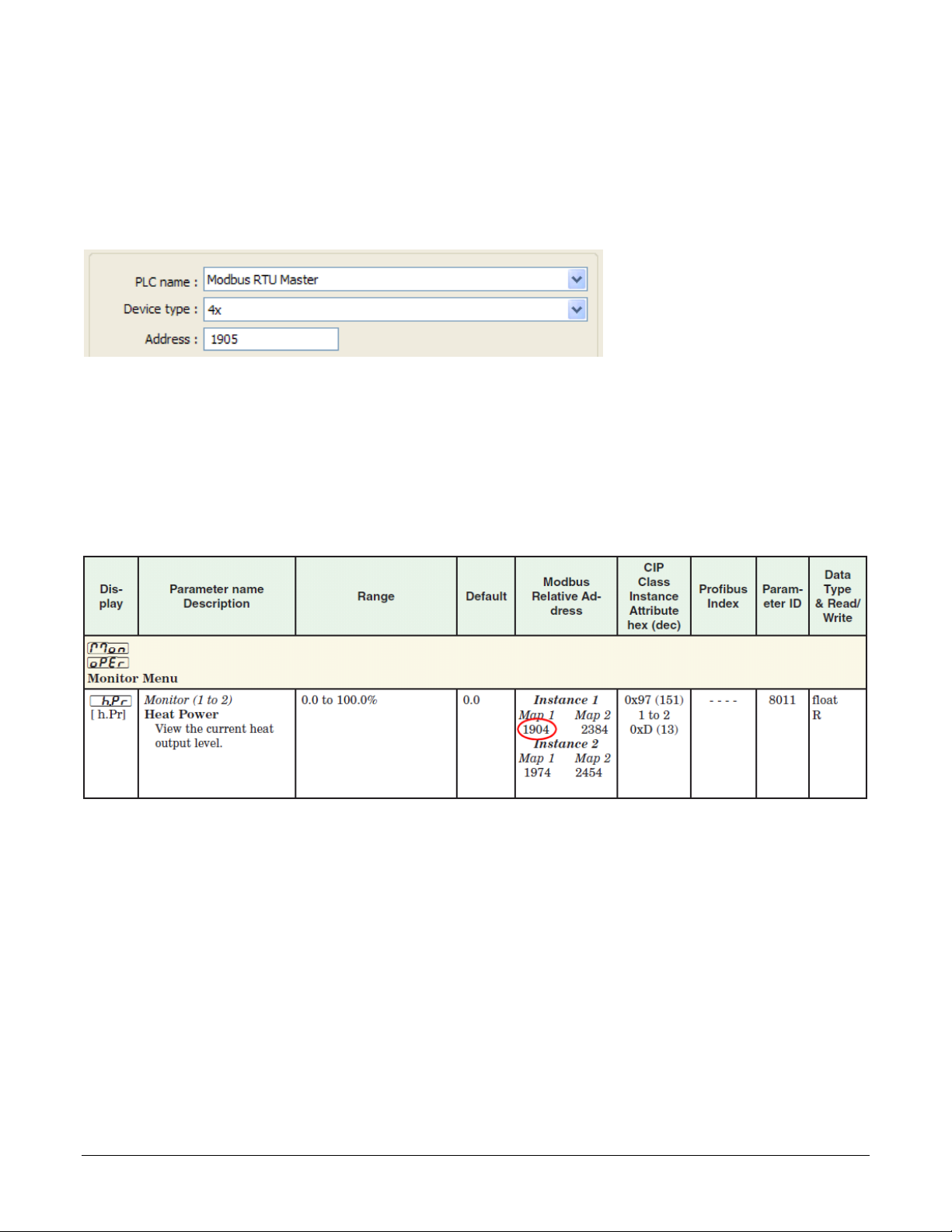
EZwarePlus’s Modbus drivers call the data block, “Device type” and for “Address” expect the memory
location’s absolute address without the data block number. For example, to access a value in a holding
register with absolute address 401,905, for Device type you select the data block “4x” and enter “1905”
in the Address field. The following illustrates setting this address in EZwarePlus.
(072)
Watlow controllers use only the 4x registers. Therefore, you will set the Device type to 4x when
accessing any parameter in a Watlow controller. Watlow manuals specify relative addresses. Therefore,
you must add one (1) to an address found in a Watlow manual (other than this manual) before you enter
it in EZwarePlus.
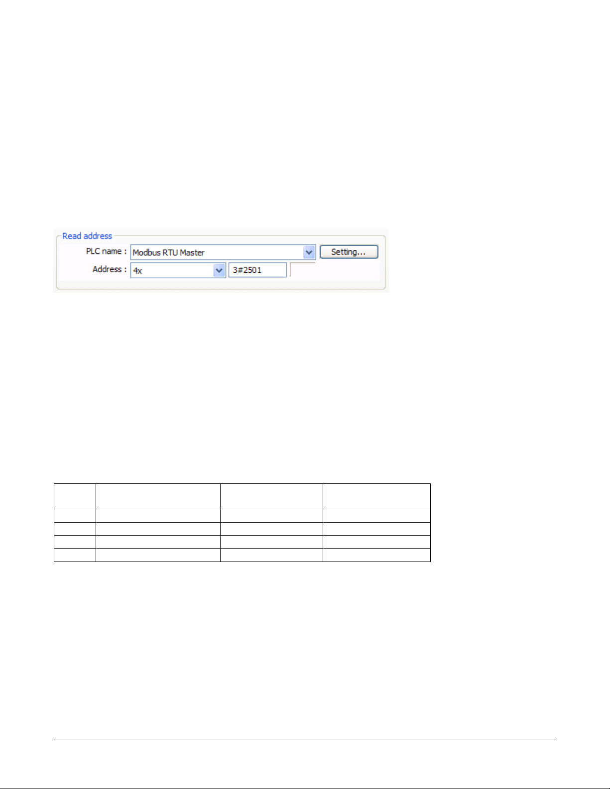
For example, the EZ-ZONE PM Integrated Controller Models User’s Manual lists the relative address
for Heat Power as 1904. To monitor the heat power with the Silver Series EM OIT, you will add one (1)
to the relative address and enter “1905” in the Address field in EZwarePlus.
(073)
In summary, when setting an address for a screen object to read or write from a Watlow controller:
• For the Device type select 4x.
• Set the Address to a value that is one greater than the relative Modbus address listed in the
Watlow controller manual.
Address Maps
Some EZ-ZONE products have user-selectable address maps. Select the desired map in the controller’s
Setup Page, Communications menu with the Data Map parameter. The Data Map affects the parameter
addresses at which values are read and written. The Data Map setting applies to all the parameters in the
controller. Generally Map 2 provides access to more parameters.
Silver Series EM OIT 7 Watlow Addendum
Page 8

For example, the EZ-ZONE PM Integrated Controller Models User’s Manual lists Map1 and Map 2
addresses for Process Value for Analog Inputs 1 and 2. If the Data Map parameter is set to Map 1 then
the Process Value for Analog Input 2 is read at address 441 (the listed address plus one), but if Data
Map is set to Map 2 then the Process Value for Analog Input 2 is read at address 451. The address for
the Process Value for Analog Input 1 is the same for Map 1 and Map 2.
(078)
Choosing a Communications Driver
When you create a project using EZwarePlus you select the drivers necessary to communicate with the
Watlow controllers and any other devices with which the Silver Series EM OIT must communicate. For
Watlow controllers, you select one of these drivers:
• Modbus RTU Master—used with Watlow controllers that support Modbus RTU and communicate
via RS-232 or RS-485.
• Modbus TCP/IP Master—used with Watlow controllers that support Modbus TCP and
communicate via Ethernet.
Using the Modbus RTU Master Driver to Communicate via 485
When you set up the Silver Series EM OIT to communicate via 485, you add a Modbus RTU Master
device to the device list in the System Parameter Settings. Only one driver is required for each COM
port on the OIT to which controllers are connected. This is true regardless of the number of controllers
that are connected to that 485 COM port. Think of the Modbus RTU Master device as a driver for the
COM port not as a driver for the controllers themselves. That is why you choose the Modbus RTU
Master driver rather than the Modbus RTU Slave driver. The controllers are slaves; the OIT’s COM port
is the master.
Using the Modbus RTU Master Driver to Communicate via 232
When you set up the OIT to communicate via a 232 COM port, you add a Modbus RTU Master device
to the device list in the System Parameter Settings. When using 232 on a COM port, only one controller
can be connected to that port.
Using the Modbus TCP/IP Master Driver to Communicate via Ethernet
When you set up the OIT to communicate with controllers via Ethernet, you add one Modbus TCP/IP
Master device to the device list in the System Parameter Settings dialog for each controller that has an
IP address with which you will communicate. For example, if the OIT must communicate with three EZ-
Silver Series EM OIT 8 Watlow Addendum
Page 9
ZONE controllers via Ethernet, add three Modbus TCP/IP Master devices to the device list in the
Convert Relative
Address
Enter in
EZwarePlus
1
2224
2224 + 1
2225
2
2224 + 70
2294 + 1
2295
3
2224 + 70 + 70
2364 + 1
2365
4
2224 + 70 + 70 + 70
2434 + 1
2435
System Parameter Settings dialog each configured to communicate with one controller.
Addressing Parameters in Multiple Controllers
Normally the Silver Series EM OIT assumes that any register address you enter when communicating
via Modbus RTU is associated with the controller at the network address you set in the PLC default
station no field in the Device Properties under the System Parameter Settings.
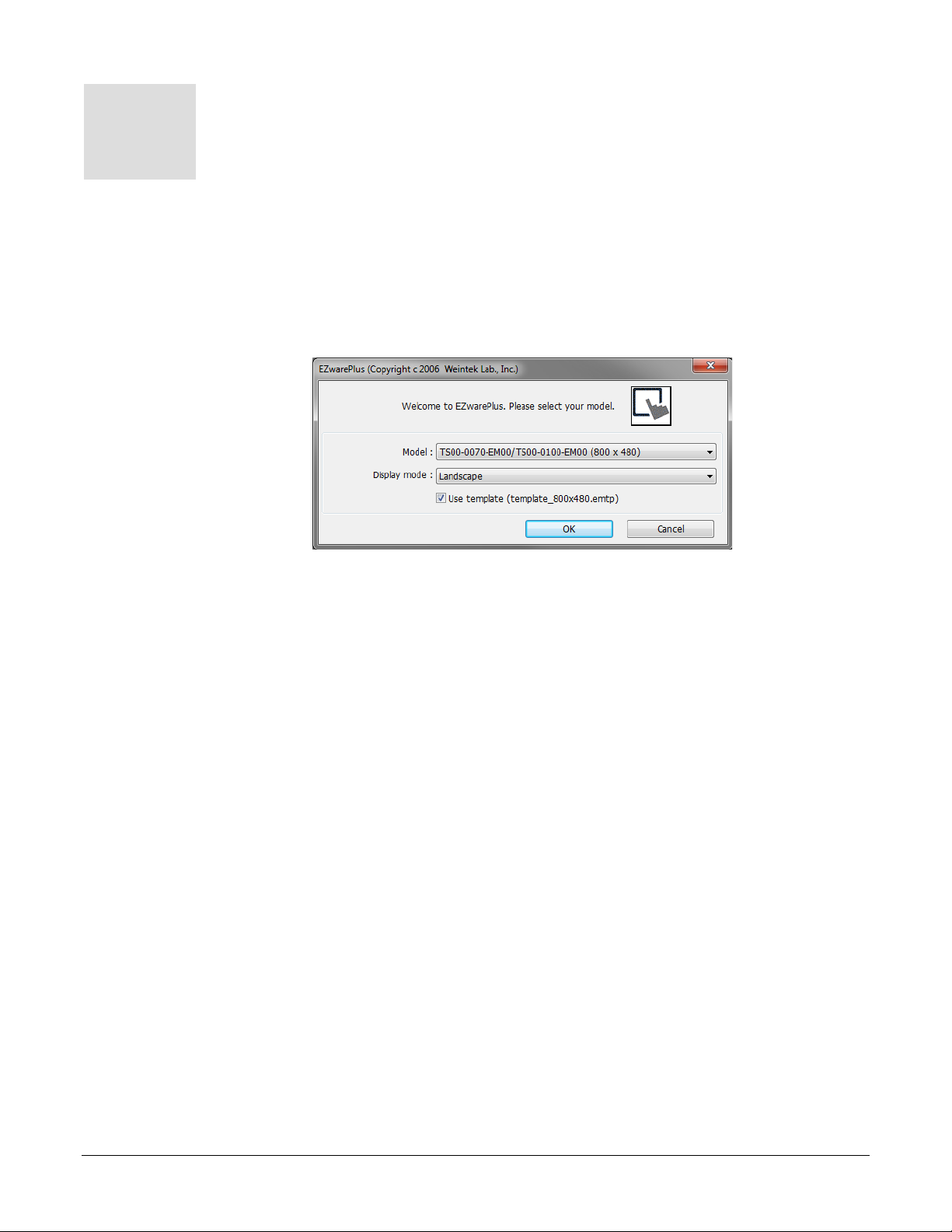
To read or write data from a register in another controller on a 485 network, enter the network address
and register address separated by the number sign or hash mark (#). For example “3#2501” accesses
register 2501 in the controller with the Modbus network address 3.
(074)
Address Offsets in Multi-Loop Controllers
In controllers with more than one loop of control, more than one limit etc., there is more than one
instance of each parameter for these duplicated functions. The manuals for controllers such as the EZZONE RM, list the Modbus address and an offset for these parameters. Add the offset to the address
once to get the address of the second instance of the parameter, add it twice to get the third instance and
so on.
For example, the address of the Heat Power for Loop 1 is listed in the EZ-ZONE RM manual as 2244
with an offset of 70. The following table lists the addresses of the Heat Power parameter for each of the
four possible loops in the controller. The table also reminds you to add one (1) to the relative addresses
from the controller manuals before entering the parameter address in EZwarePlus.
Loop Address + Offset(s)
Accessing Parameters via EZ-ZONE RUI Gateways and RM Access Modules
Multiple EZ-ZONE devices can communicate with the Silver Series EM OIT via one or more EZ-ZONE
RUI Gateways or EZ-ZONE RM Access modules. When ordered with either the Modbus TCP or
Modbus RTU communications option, an RUI Gateway or RM Access module allows a Silver Series
EM OIT to communicate with multiple EZ-ZONE controllers without purchasing communication
options in each controller.
Silver Series EM OIT 9 Watlow Addendum
Page 10

In such a system the Silver Series EM OIT is connected to and configured to communicate with the
Convert Relative
Address
Enter in
EZwarePlus
1
2172
2172 + 0
2172 + 1
2173
2
2172
2172 + 5000
7172 + 1
7173
3
2172
2172 + 10000
12172 + 1
12173
EZ-ZONE User’s
Manuals
EZ-ZONE ALL
Modbus List
Enumeration,
unsigned 16-bit
dint
signed 32-bit
32-bit Signed
float
IEEE Float
32-bit Float
gateway. The gateway presents itself as a single device on the Modbus network; the OIT does not
communicate with the controllers, only with the gateway. The gateway is configured by the user with an
address offset for each controller connected to it. That address offset is added to the parameter addresses
for the controller.
For example, consider three EZ-ZONE PM controllers connected to an RUI Gateway configured with an
offset of 0 for the first controller, 5000 for the second controller and 10,000 for the third controller. The
table below indicates the addresses that must be entered in EZwarePlus to access the set point value in
the three PM controllers.
PM Set Point Plus Gateway Offset
Data Types
The Silver Series EM OIT’s Modbus drivers support a variety of data types. The Watlow manuals
specify the data type of each parameter. However the terminology is not precisely the same. The table
below correlates the data types indicated in the Watlow documentation with the data types you should
select when configuring a screen object in EZwarePlus.
EZwarePlus
uint
unsigned 8-bit,
Event,
16-bit Unsigned
Important Things to Know
Note: Make sure the Modbus Word Order is set to Word Low High in the controller.
That is the setting that works with the Silver Series EM OIT.
Note: Examples in this manual use the map 1 addresses. If the controller’s Data Map is
set to 2, the examples may not work.
Caution: When using a multi-state switch object to set an enumerated parameter in a
controller, each time the user clicks the switch, the setting selected by the switch
is sent to the controller. When it is desirable to go directly from one setting to
another without intermediate settings, use a set word object or an option list to
set the parameter instead.
Silver Series EM OIT 10 Watlow Addendum
Page 11
Chapter 4: Programming
1) To launch
4
Tutorials
The following sections guide you through creating a first project using EZwarePlus and a Silver Series
EM OIT that communicates with a Watlow controller.
Create a First Project
The following procedure guides you through the process of configuring a Silver Series EM OIT to
communicate with a Watlow Controller.
EZwarePlus: on
the Windows task
bar click Start,
click All
Programs, click
Watlow, click
EZwarePlus and
click EZwarePlus.
(001)
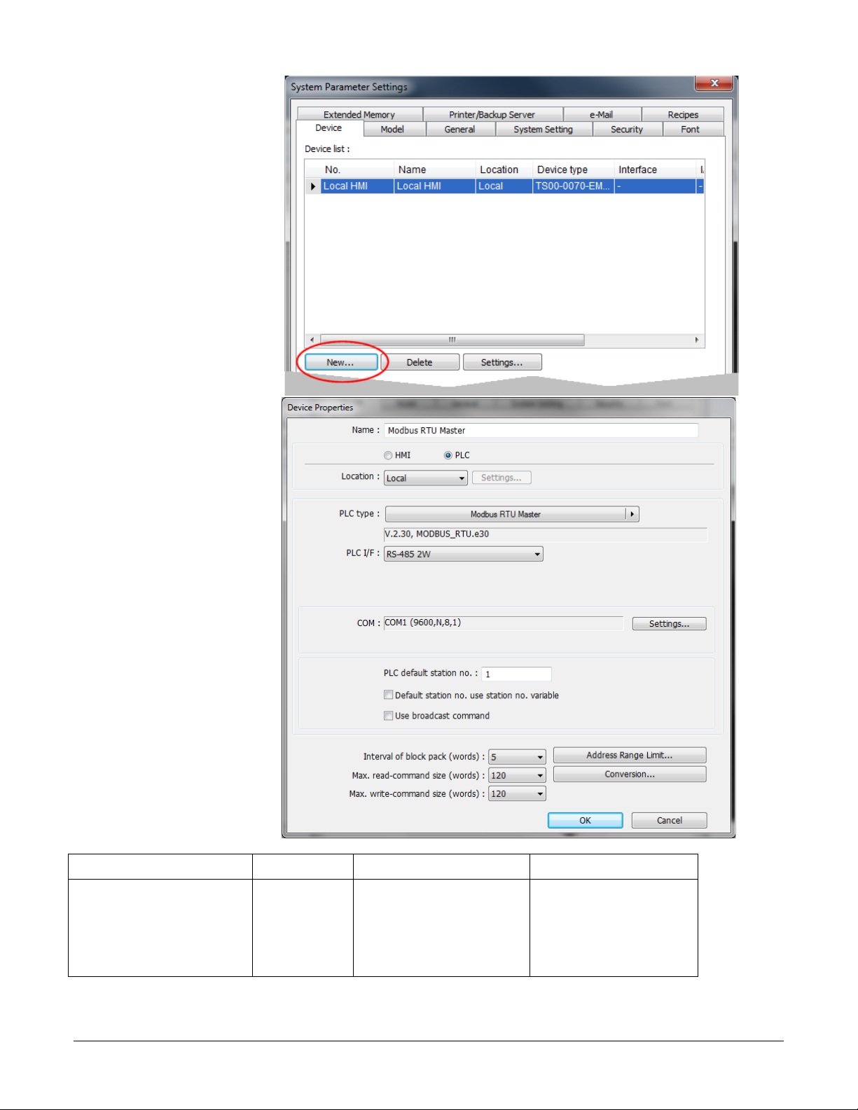
2) In the Welcome to
3) For Display Mode
4) Make sure Use
5) Click OK.
EZwarePlus
dialog, for Model,
choose the OIT
model you have.
choose Landscape.
template is
selected.
Note: If you have previously created a project, that project will open. In
that case from the File menu, choose New to create a blank project for
this tutorial and to see the Welcome dialog.
Note: The TS00-0070-EM00 and TS00-0100-EM00 are supported by
the same driver.
Silver Series EM OIT 11 Watlow Addendum
Page 12
6) In the System
Parameter
(002)
7) For PLC type,
(003)
STxx-xxx-xxxx
RMSx-xxxx-x1xx
Settings dialog,
under the Device
List, click New…
choose the
appropriate driver.
See the table
below.
8) For PLC I/F,
choose the
appropriate
hardware interface.
See the table
below.
9) For PLC default
station no. type
the controller’s
address. Typically
this is 1 for the
first controller.
10) Click Settings…
For part numbers like… with… For PLC type choose… For PLC I/F choose…
PMxxxxx-1xxxxxx
RMCxxxx-xxxx1xx
RMHx-xxxx-x1xx
RMLx-xxxx-x1xx
Modbus RTU Modbus RTU Master RS-485 2W
Silver Series EM OIT 12 Watlow Addendum
Page 13
For part numbers like… with… For PLC type choose… For PLC I/F choose…
PMxxxxx-3xxxxxx
RMAx-x3xx-xxxx
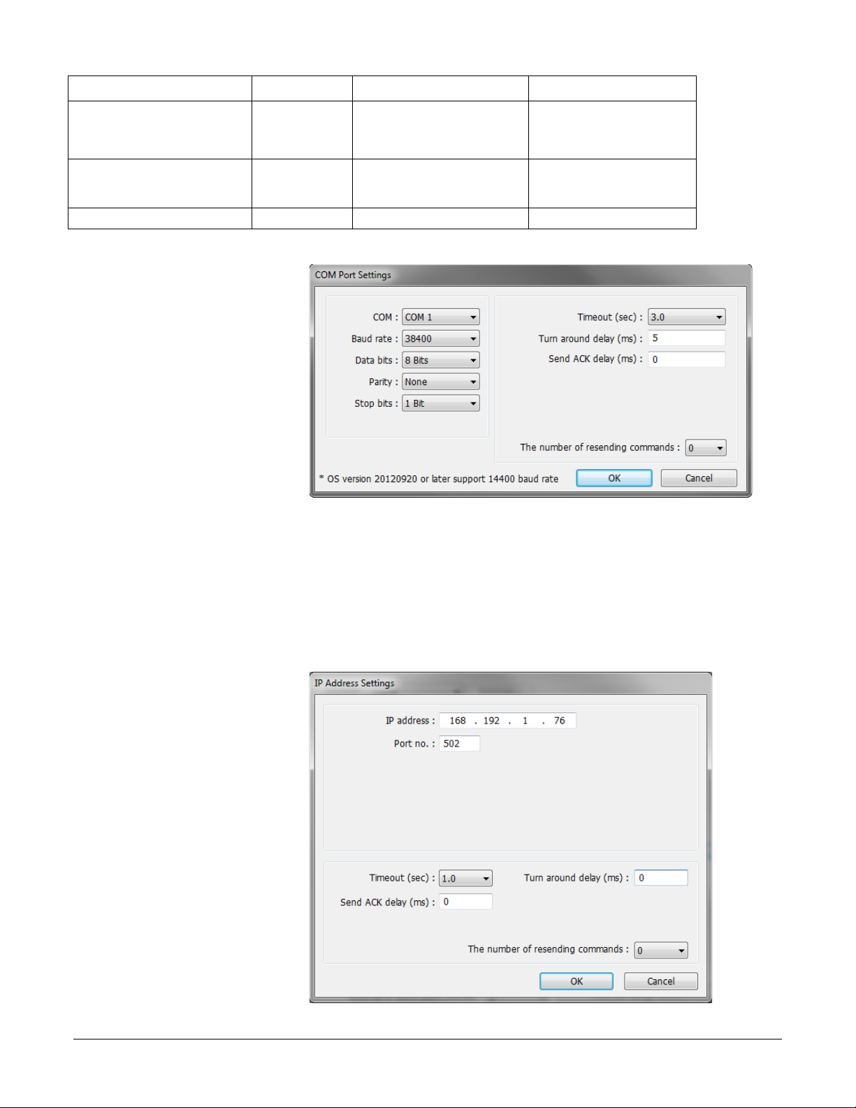
11) For the Modbus RTU
• For Data bits, choose 8 Bits.
12) For the Modbus
(005)
PMxxxxx-2xxxxxx
EZKx-2xxx-xxxx
RMAx-x2xx-xxxx
Modbus RTU Modbus RTU Master RS-232 or RS-485 2W*
EZKx-3xxx-xxxx
Other Watlow Controllers Modbus RTU Modbus RTU Master RS-232 or RS-485 2W*
*Both 232 and 485 are available; choose the one to which you have connected the OIT.
Modbus TCP Modbus TCP/IP Master Ethernet
Master…
• For COM, choose the
communications port to
which you have
connected the
controller. Typically
this is COM 1.
• For Baud rate, choose
the rate that is set in the
controller.
• For Parity, choose None.
• For Stop bits, choose 1 Bit.
(004)
• For multiple controllers on the same port, for Turn around delay (ms), enter 15 and for Send
ACK delay (ms) enter 15.
• Click OK.
TCP/IP Master…
• For IP address, enter
the IP address of the
controller.
• Click OK.
13) Click OK to close the
Device Properties
dialog.
Silver Series EM OIT 13 Watlow Addendum
Page 14
14) To set up communications with controllers connected to other COM ports or to configure
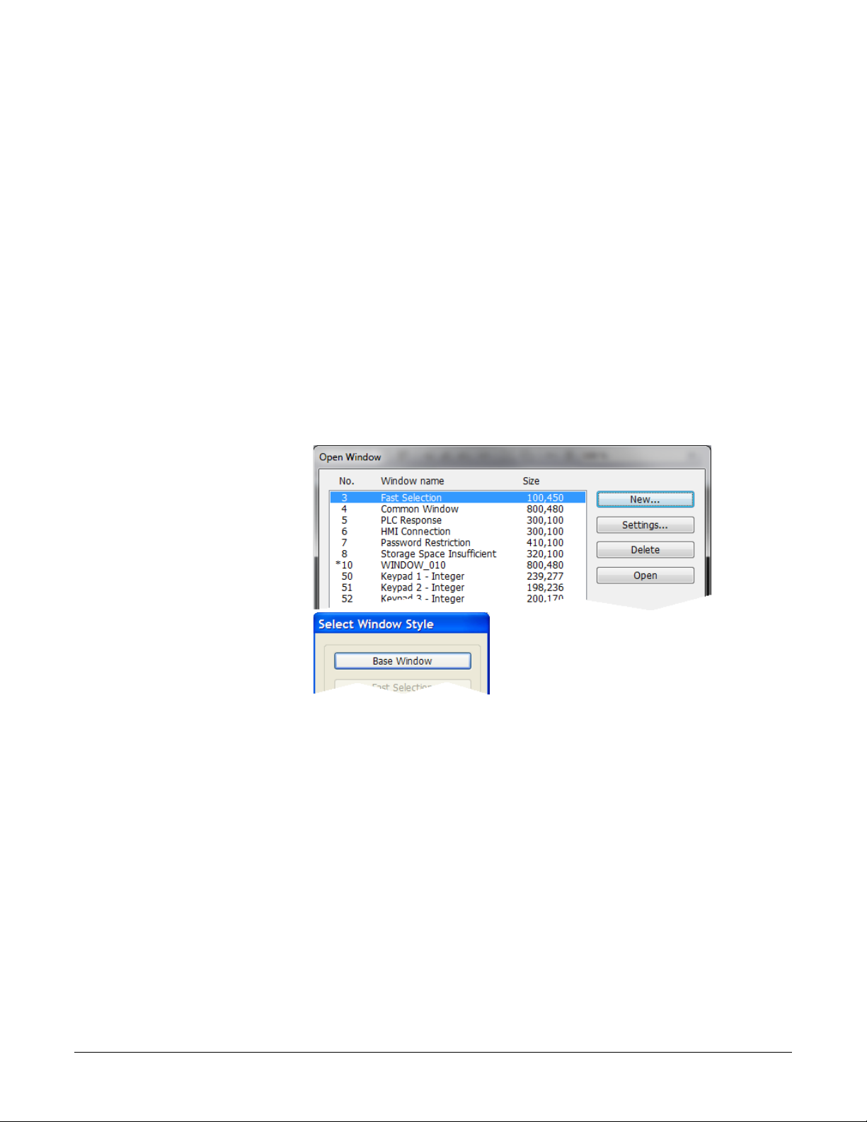
1) From the Window
(006)
3) Click Base Window.
(007)
additional controllers communicating via Ethernet:
• Click New...
• Repeat from step 7 above.
15) Click OK to close the System Parameter Settings dialog.
16) Save the project:
• From the File menu, choose Save.
• In File name type First Project.emtp.
• Click Save.
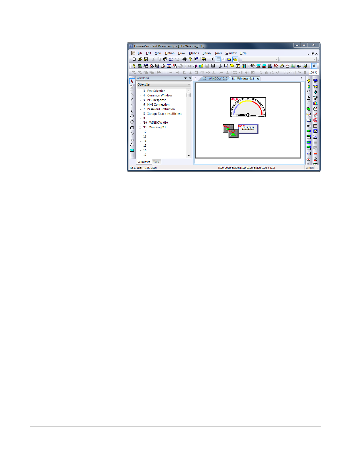
Create a Popup Window
This example assumes you have created a project that is configured to communicate with a Watlow
controller and that project is open in EZwarePlus.
menu, choose Open
Window.
2) Click New…
Silver Series EM OIT 14 Watlow Addendum
Page 15
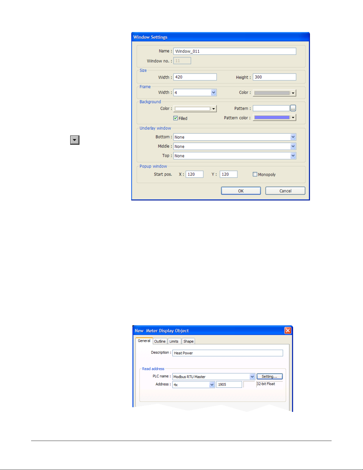
4) Ensure the Name is
Window_011 and the
(008)
1) From the Objects
Window no. is 11.
5) Set Width to 420.
6) Set Height to 300 (272
for the 4.3 in. OIT).
7) To set the background
color to white:
• In the Background
group, next to Color
click .
• Select the white color
swatch.
• Click OK.
8) In the Popup window group, set Start pos. X to 120 (0 for the 4.3 in. OIT).
9) In the Popup window group, set Start pos. Y to 120 (0 for the 4.3 in. OIT).
10) Click OK.
11) In the Open Window dialog, select Window_11.
12) Click Open.
13) From the File menu choose Save.
Create a Meter in a Popup Window
This example assumes you have created a popup window in a project that is configured to communicate
with a Watlow Controller and that window is open in EZwarePlus.
menu, choose Meter
Display.
2) Click the General tab.
3) In Description type
Heat Power.
4) Click Setting…
Silver Series EM OIT 15 Watlow Addendum
(009)
Page 16

5) For PLC name choose
the Modbus Master or
For this
controller…
This
parameter…
Enter this
Address*…
Choose this
Data Type…
RMCxxxx-xxxxxxx
Heat Power
2245
32-bit Float
RMHx-xxxx-x1xx
Heat Power
4125
32-bit Float
PMxxxxx-xxxxxxx
Heat Power
1905
32-bit Float
STxx-xxMx-xxxx
Heat Power
237
32-bit Float
ST via RUI Gateway
Heat Power
1901
32-bit Float
Other Controllers
Consult the controller manual.
Modbus TCP/IP
Master.
6) For Device type
choose 4x.
7) For Address enter the
address of the heat
power for your
controller. See the
table.
8) Select the data type in
the field below the
Address field. See the
table.
9) Click OK.
(075)
*These addresses have already been changed to the absolute form
required for EZwarePlus by adding 1 to the value listed in the Watlow
manual. Enter them as listed
Silver Series EM OIT 16 Watlow Addendum
Page 17

10) Click the Outline tab.
11) In Degree set Start
(010)
19) Click the Limits tab.
(011)
24) Click OK.
degree to 270.
12) In Degree set End
degree to 90.
13) In Background
uncheck Full circle.
14) In Tick marks check
Enable.
15) For Tick marks
Color, select black.
16) In Tick marks set
Main scale to 6.
17) In Tick marks set Sub
scale to 1.
18) In Tick marks set
Length to 6.
20) Set Value Zero to 0.
21) Set Value Span to
100.
22) Check Range limits
Enable.
23) Set Width to 3.
25) Move the cursor with the outline of the meter to position it and click to place the meter in
Window_11.
26) Resize the meter with the corner handles to make it smaller, if necessary
Silver Series EM OIT 17 Watlow Addendum
Page 18

27) Double-click the meter
to open the Meter
1) On the Objects menu,
For this
controller…
This
parameter…
Enter this
Address*…
Choose this
Data Type…
RMCxxxx-xxxxxxx
2513
32-bit Float
RMHx-xxxx-x1xx
5233
32-bit Float
PMxxxxx-xxxxxxx
2173
32-bit Float
STxx-xxMx-xxxx
204
32-bit Float
ST via RUI Gateway
2173
32-bit Float
Other Controllers
Consult the controller manual.
Display Object’s
Properties dialog.
28) Click the Profile tab.
29) Set X to 140.
30) Set Y to 60.
(012)
31) Set Width to 140.
32) Set Width (%) to 100.
33) Click OK.
34) From the File menu
choose Save.
Add a Numeric Display
This example assumes you have created a window in a project that is configured to communicate with a
Watlow Controller and that window is open in EZwarePlus.
click Numeric/ASCII
then choose Numeric
Display.
2) Click the General
tab.
3) In Description type
Actual Closed Loop
Set Point.
4) For PLC name
choose Modbus RTU
Master or Modbus
TCP/IP Master.
5) For Address choose
4x and enter the
address of the Closed
Loop Working/Active
Set Point for your
controller. See the
table.
Silver Series EM OIT 18 Watlow Addendum
(013)
Closed Loop
Working/Active
Set Point
(Read Only)
*These addresses have already been changed to the absolute form required
for EZwarePlus by adding 1 to the value listed in the Watlow manual. Enter
them as listed.
Page 19
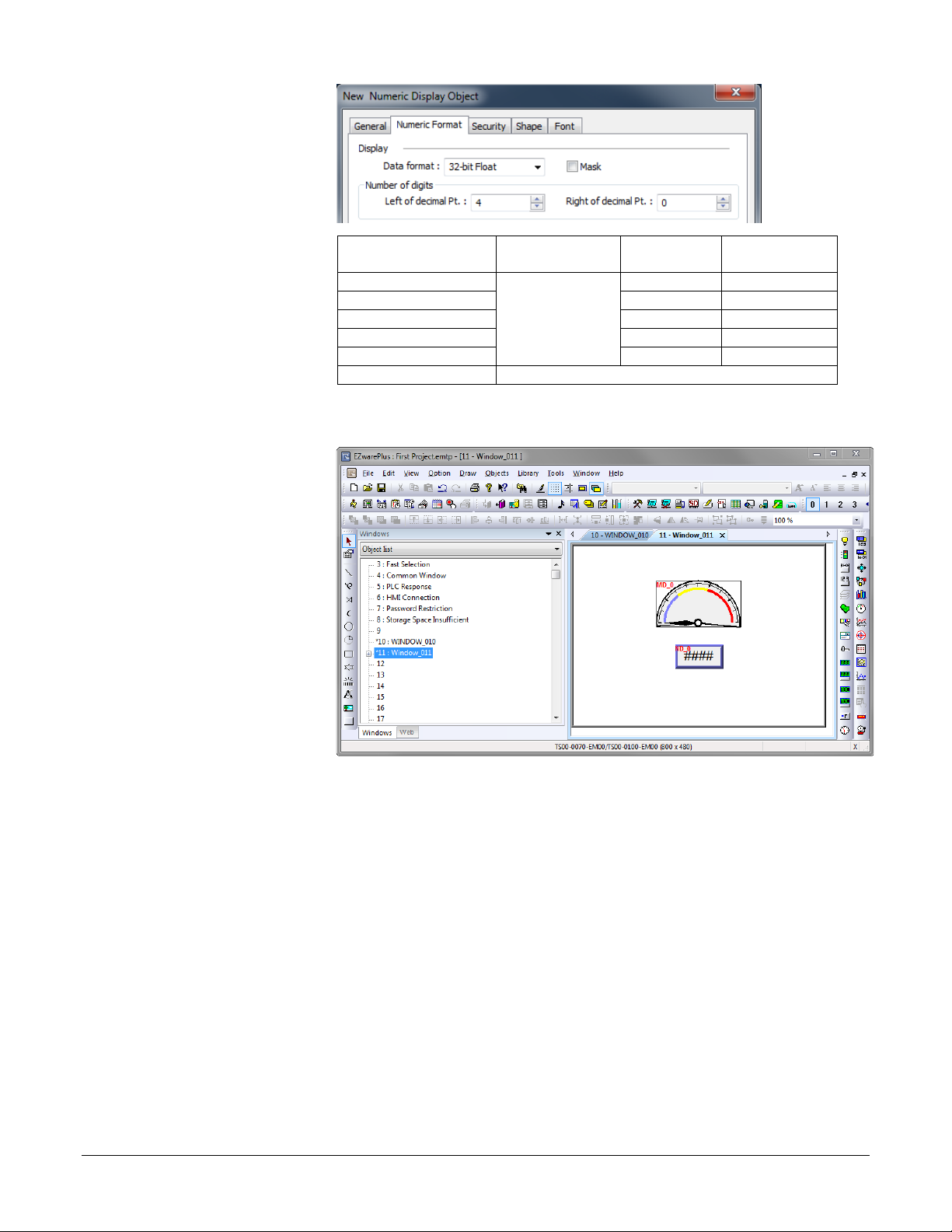
6) On the Numeric
Format tab.
For this
controller…
This
parameter…
Enter this
Address*…
Choose this
Data Type…
RMCxxxx-xxxxxxx
2513
32-bit Float
RMHx-xxxx-x1xx
5233
32-bit Float
PMxxxxx-xxxxxxx
2173
32-bit Float
STxx-xxMx-xxxx
204
32-bit Float
ST via RUI Gateway
2173
32-bit Float
Other Controllers
Consult the controller manual.
10) Move the cursor with
7) In Data format set
the data type. See the
table.
8) On the Font tab set
Align to Right.
(013b)
9) Click OK.
the outline to position
the display field and
click to place it.
11) Adjust the size of the
field as needed.
12) From the File menu
choose Save.
Closed Loop
Working/Active
Set Point
(Read Only)
*These addresses have already been changed to the absolute form required
for EZwarePlus by adding 1 to the value listed in the Watlow manual. Enter
them as listed.
Silver Series EM OIT 19 Watlow Addendum
(014)
Page 20

Add Increment and Decrement Buttons
1) On the Objects menu,
This
parameter…
Enter this
Address*…
Choose this
Data Type…
RMCxxxx-xxxxxxx
2501
32-bit Float
RMHx-xxxx-x1xx
5221
32-bit Float
PMxxxxx-xxxxxxx
2161
32-bit Float
STxx-xxMx-xxxx
22
32-bit Float
ST via RUI Gateway
2161
32-bit Float
Other Controllers
Consult the controller manual.
This example assumes you have created a window in a project that is configured to communicate with a
Watlow Controller and that window is open in EZwarePlus.
To add a button that increments the set point:
click Button then
choose Set Word.
2) Click the General tab.
3) In Description type
Increment Set Point.
4) For PLC name choose
Modbus RTU Master
or Modbus TCP/IP
Master.
5) Click Setting…
6) For Device type
choose 4x.
7) For Address enter the
address of the User Set
For this controller…
Point for your
controller.
8) Select the data type for
the parameter in the
Closed Loop
Set Point
(Read/Write)
field below the
Address field.
9) Click OK.
*These addresses have already been changed to the absolute form required
for EZwarePlus by adding 1 to the value listed in the Watlow manual. Enter
them as listed.
10) In Attribute for Set
Style choose Press and
hold increment
(JOG++).
11) Set Inc. value to 1.
12) Set Upper Limit to 100 or a value that is safe for your controller’s set point.
13) Set JOG delay to 0.5 seconds.
14) Click the Shape tab.
(015)
15) Check Use shape.
Silver Series EM OIT 20 Watlow Addendum
Page 21

16) Click Shape
Library…
23) Click to place the
17) Click the new library
icon Select Lib…
18) In the EZwarePlus
program’s library
directory (typically:
C:\Watlow\EZPlus\libr
ary) select Arrows
1.plb.
19) Click Open.
20) Locate the button with
the triangular arrow
pointing up and click
it.
21) Click OK to close the
Shape Library.
22) Click OK to close the
New Set Word Object
dialog.
button.
(016a)
(016)
24) Use the handles to
adjust the size of the
button.
25) Drag the button to
place it as desired on
the screen.
26) From the File menu
choose Save.
(017)
Silver Series EM OIT 21 Watlow Addendum
Page 22
To add a button that decrements the set point:
1) Click the increment
(018)
button to select it.
2) From the Edit menu,
choose Copy.
3) From the Edit menu,
choose Paste.
4) Drag the new button to
an appropriate
position.
5) Double click the new
button to edit its
properties.
6) On the General tab change:
• Description to Decrement Set Point
• Set Style to Press and hold decrement (JOG--).
7) Set Bottom Limit to 0.
8) On the Shape tab click Shape Library…
9) Locate the button with the triangular arrow pointing down and click it.
10) Click OK to close the Shape Library.
11) Click OK to close the Set Word Object Properties dialog.
12) From the File menu choose Save.
Silver Series EM OIT 22 Watlow Addendum
Page 23
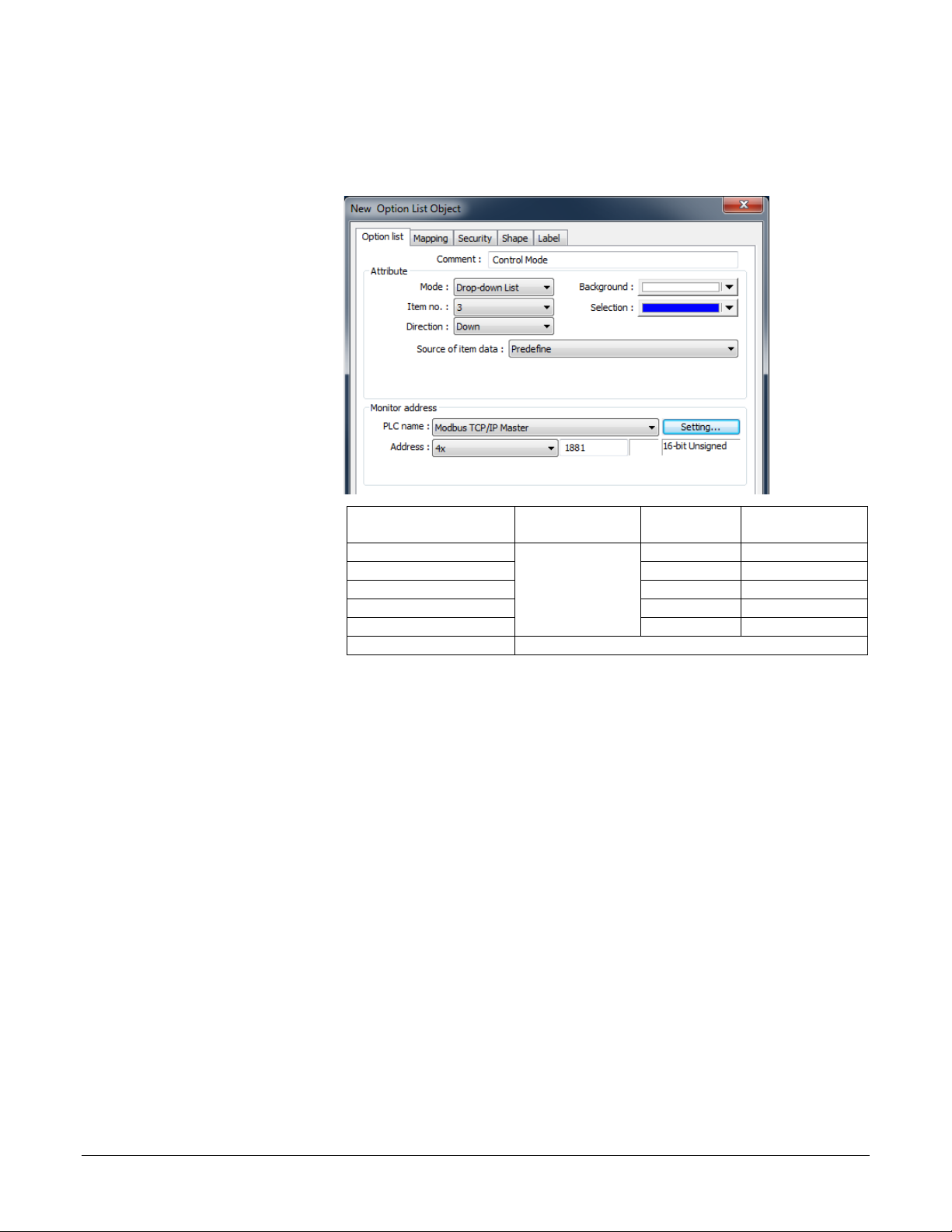
Add an Option List for Control Mode
1) On the Objects menu,
This
parameter…
Enter this
Address*…
Choose this
Data Type…
RMCxxxx-xxxxxxx
2221
16-bit Unsigned
RMHx-xxxx-x1xx
4101
16-bit Unsigned
PMxxxxx-xxxxxxx
1881
16-bit Unsigned
STxx-xxMx-xxxx
222
16-bit Unsigned
ST via RUI Gateway
1881
16-bit Unsigned
Other Controllers
Consult the controller manual.
This example assumes you have created a window in a project that communicates with a Watlow
Controller and that window is open in EZwarePlus.
click Button then
choose Option List.
2) Click the General tab.
3) In Comment type
Control Mode.
4) Set Mode to Dropdown list.
5) Set Item No. to 3.
6) In the Monitor
address group:
• For PLC name choose
Modbus RTU Master or
Modbus TCP/IP
Master.
• Click Setting…
• For Device type choose
4x.
• In Address enter the
address of the Control
Mode. See the table.
• Select the data type in
the field below the
Address field.
• Click OK to close the
Address dialog
7) Click the Mapping
tab.
(019)
For this controller…
Control Mode
*These addresses have already been changed to t he absolute form required
for EZwarePlus by adding 1 to the value listed in the Watlow manual. Enter
them as listed.
Silver Series EM OIT 23 Watlow Addendum
Page 24

8) In the Values column
type the numeric and in
Item
Value
Enumerated Value
0
10
Auto 1 54
Manual
2
62
Off
3 (error)
10) Position the cursor
the Item data the text
that corresponds to
each option you want
to include. See the
table.
9) Click OK to close the
New Option List
Object dialog.
near the bottom center
of the window layout
and click to place the
multi-state switch.
(You may have to
move the other objects
around to fit
everything.)
(020)
11) From the File menu
choose Save.
(022)
Silver Series EM OIT 24 Watlow Addendum
Page 25
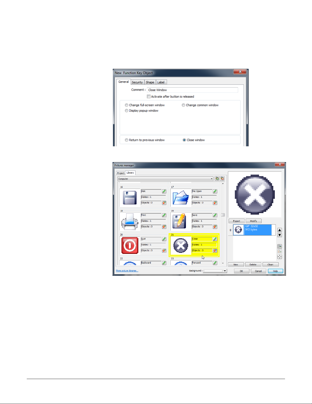
Add a Button to Close the Popup Window
1) On the Objects menu,
6) Click Picture
This example assumes you have created a window in a project that communicates with a Watlow
Controller and that window is open in EZwarePlus.
click Button then
choose Function Key.
2) On the General tab, in
Comment type Close
Window.
3) Select Close window.
4) On the Shape tab,
uncheck Use shape.
5) Check Use picture.
Library…
7) Click the new library
icon
(023)
8) Select Computer.flb.
9) Click Open.
10) Locate the circular
grey button with the
white x and click to
select it.
11) Click OK to close the
Picture Library.
12) On the Label tab,
make sure Use label is
not checked.
13) Click OK to close the New Function Key Object dialog.
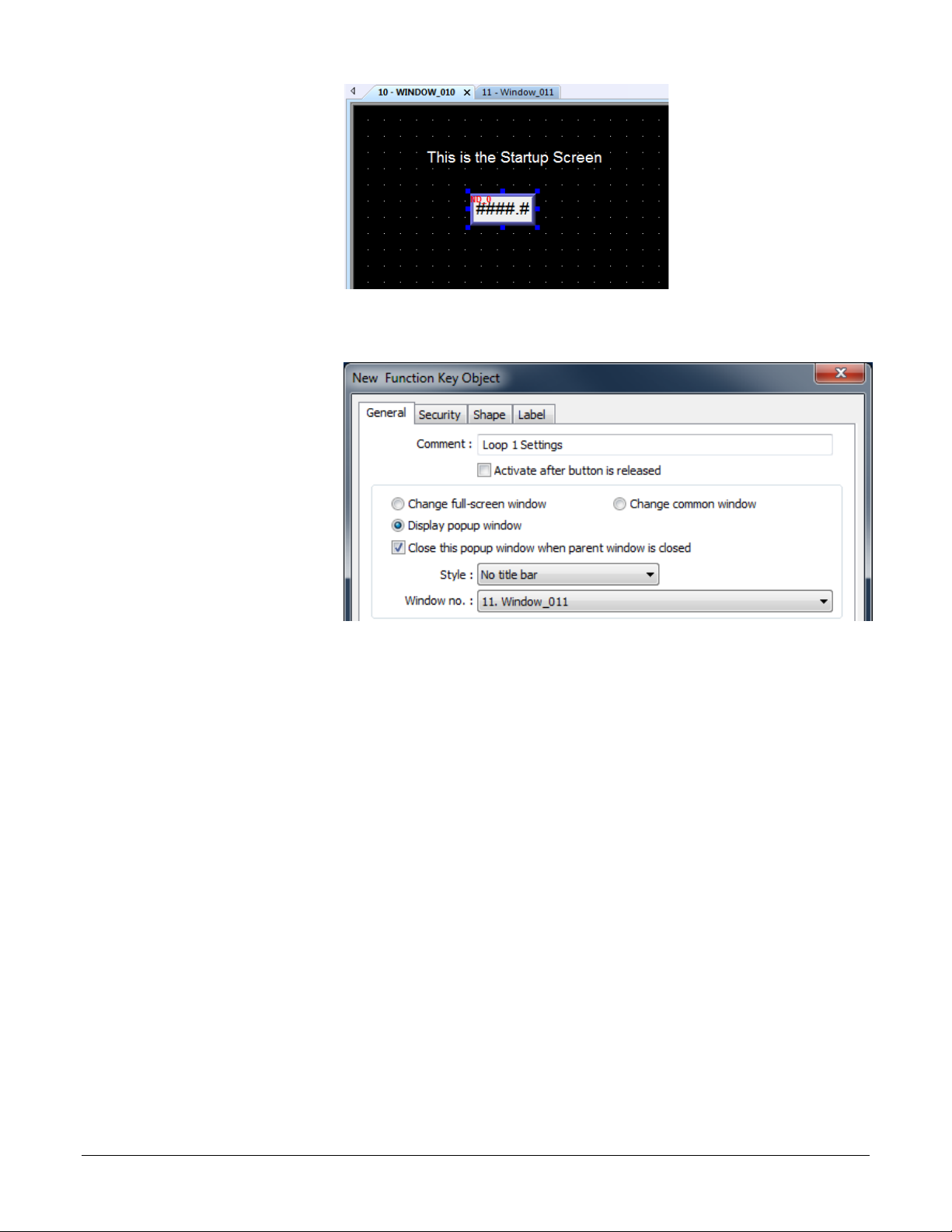
14) Click to place the function key in the upper right.
15) Double-click the function key to open the Function Key Object’s Properties dialog.
(024)
Silver Series EM OIT 25 Watlow Addendum
Page 26
16) Click the Profile tab
17) Set Position X to 375.
1) From the Window
18) Set Position Y to 5.
19) Set Size Width to 40.
20) Set Size Height to 40.
21) Click OK.
22) From the File menu
choose Save.
(025)
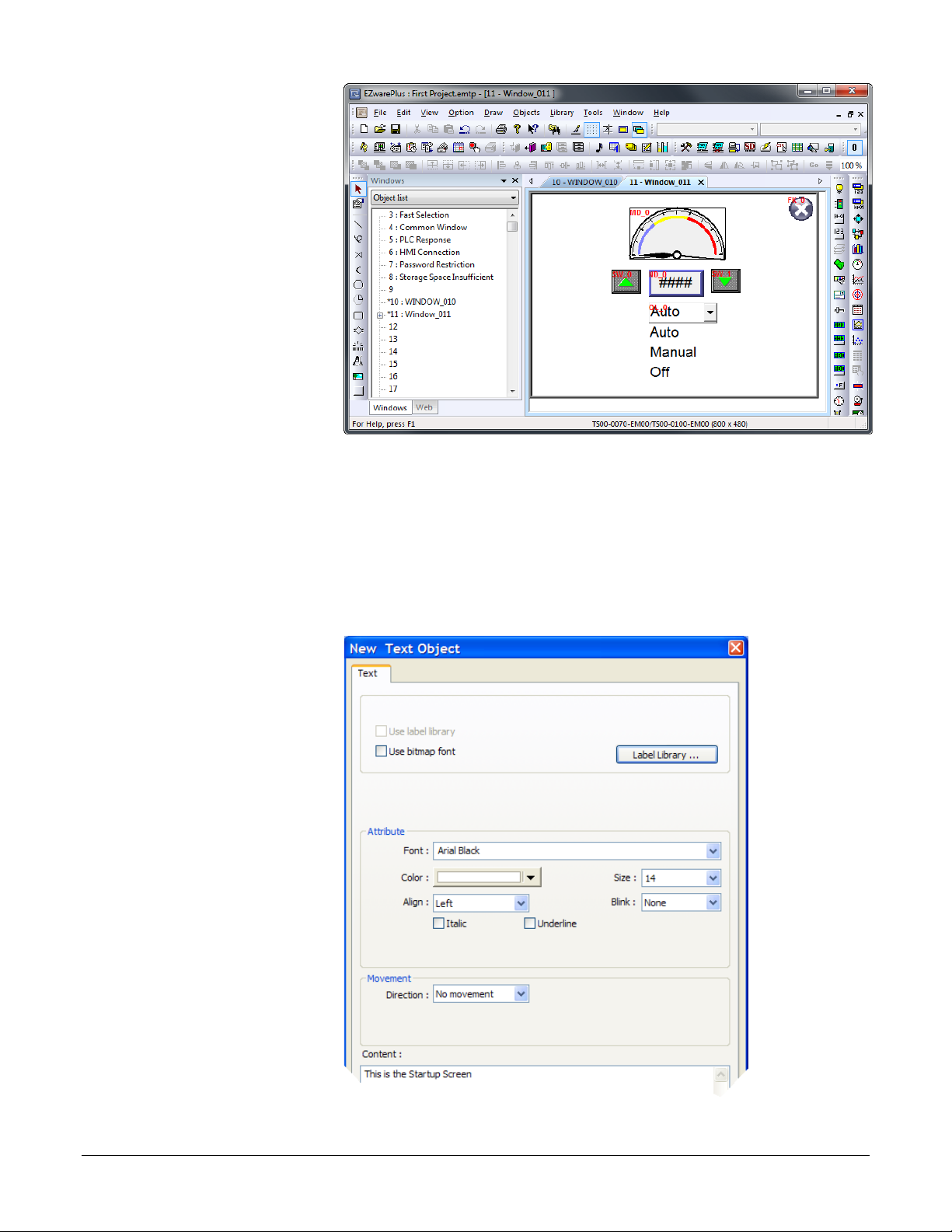
Edit the Startup Window
This example assumes you have created a popup window open in EZwarePlus in a project that is
configured to communicate with a Watlow Controller.
To add text to the start up window:
menu, choose 1 10 –
WINDOW_010.
2) From the Draw menu
choose Text.
3) Set these text
Attributes:
• Choose a Font.
• Set Color to white.
• Set Size to 14.
• Set Align to Left.
4) Edit Content to read,
This is the Startup
Screen.
5) Click OK.
(026)
Silver Series EM OIT 26 Watlow Addendum
Page 27

6) Position the cursor centered in the top third of the window layout and click to place the text.
1) On the Objects menu,
This
parameter…
Enter this
Address*…
Choose this
Data Type…
RMCxxxx-xxxxxxx
361
32-bit Float
RMHx-xxxx-x1xxx
381
32-bit Float
PMxxxxx-xxxxxxx
361
32-bit Float
STxx-xxMx-xxxx
20
32-bit Float
ST via RUI Gateway
361
32-bit Float
Other Controllers
Consult the controller manual.
6) Click the Numeric
9) On the Font tab set
7) From the File menu choose Save.
Add a Numeric Display to the main window:
click Numeric/ASCII
and choose Numeric
Display.
2) Click the General tab.
3) In Description type
Process Variable.
4) For PLC name choose
Modbus RTU Master
or Modbus TCP/IP
Master.
5) For Address choose
4x.and enter the
address of the Analog
Input 1 Process Value.
See the table.
Format tab.
7) In Data format set the
data type.
8) Set Right of decimal
Pt. to 1.
Align to Right.
(027)
For this controller…
Analog Input 1
Process Value
*These addresses have already been changed to the absolute form required
for EZwarePlus by adding 1 to the value listed in the Watlow manual. Enter
them as listed.
(028)
10) Click OK.
Silver Series EM OIT 27 Watlow Addendum
(029)
Page 28
11) Move the cursor with
the outline to position
1) On the Objects menu,
the display field in the
center of the screen
and click to place it.
12) From the File menu
choose Save.
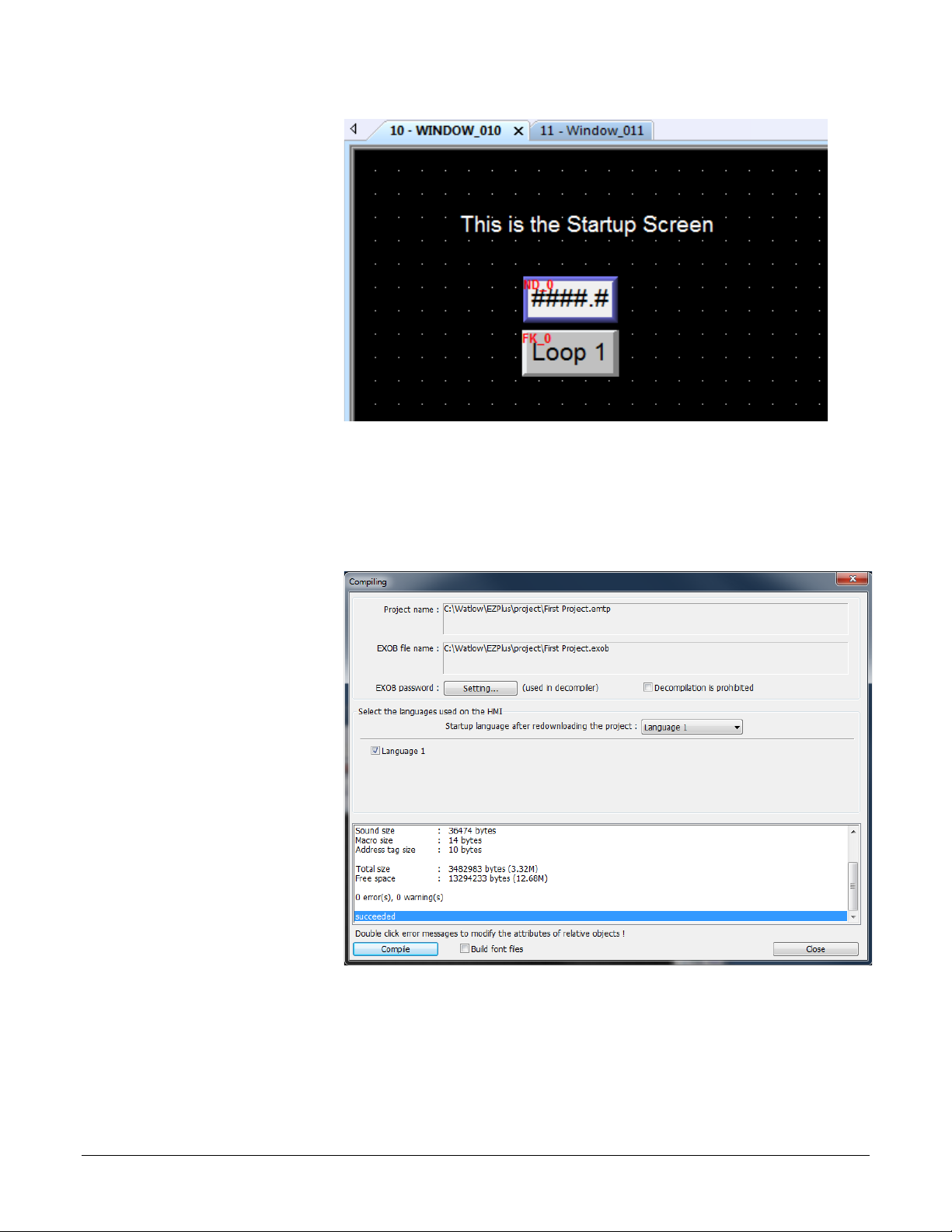
To create a function key on Window10:
click Button then
choose Function Key.
2) On the General tab, in
Comment type Loop 1
Settings.
3) Select Display popup
window.
(030)
4) For Style choose No
title bar.
5) For Window no. select 11. Window_011.
6) Click the Shape tab.
7) Check Use shape.
8) Click Shape Library…
9) In the Library list select buttons1.
10) Click one of the buttons to select it.
11) Click OK to close the Shape Library.
12) Click the Label tab.
13) Check Use label.
14) Set Color to black.
15) Set Size to 16.
16) Set Align to Left.
(031)
17) In Content type Loop 1.
Silver Series EM OIT 28 Watlow Addendum
Page 29
18) Click OK.
19) Position the cursor and
1) From the Tools menu,
click to place the
function key.
20) From the File menu
choose Save.
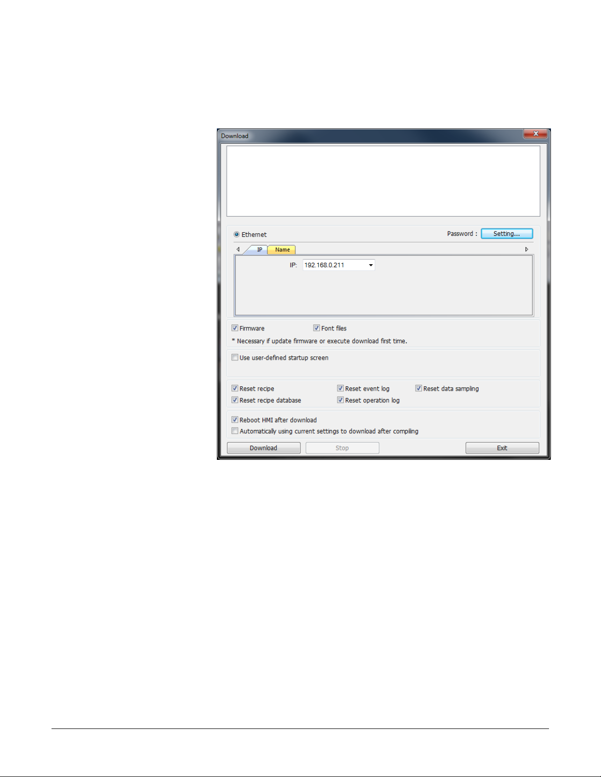
Compile and Download the Project
This example assumes you have a project that is ready to compile and load into an OIT.
To compile the project:
(032)
choose Compile.
2) Click Compile.
3) After the project is
compiled, click Close.
(034)
Silver Series EM OIT 29 Watlow Addendum
Page 30
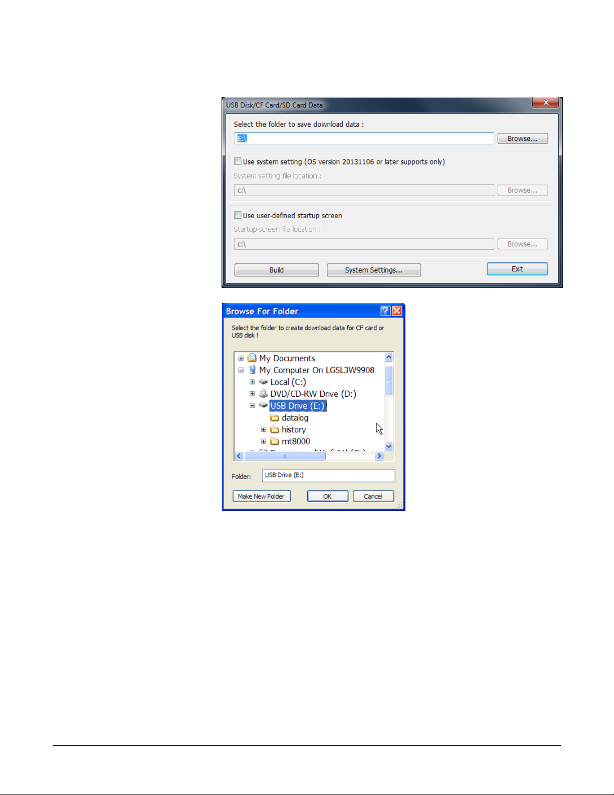
To download via Ethernet:
2) In EZwarePlus from
1) Determine the OIT’s IP address:
• If you don’t already know the OIT’s IP address, follow the instructions in Determining or
Setting the OIT’s IP Address on page 4, note the IP address for use below.
the Tools menu,
choose Download.
3) HMI IP select or enter
the OITs IP address.
4) Set Password to the
OITs password
(111111 by default).
5) Check Firmware, if
not already checked.
6) Check Reboot HMI
after download, if not
already checked.
7) Click Download.
8) Once the download is
complete, click Exit.
(035)
Silver Series EM OIT 30 Watlow Addendum
Page 31
To download the project via a USB drive to an OIT:
2) From the Tools menu
4) Locate and select the
1) Connect at USB drive to the PC
choose Build Data for
USB Disk or SD Card
Download…
3) Click Browse…
(038)
USB drive.
Note: Do not select a sub
directory of the USB drive.
Select the root.
5) Click OK to close the
Browse For Folder
dialog.
6) Click Build.
7) When the files are transferred successfully, click OK.
8) Click Exit to close the USB Disk/CF Card/SD Card Data dialog.
9) Remove the USB drive from the PC.
To download the from the USB drive to the OIT:
1) Connect the USB drive to the OIT.
2) When the download/Upload screen appears on the OIT click Download.
(039)
Note: You only have a few seconds to do this before the screen times out. If you miss it, disconnect the
USB drive and connect it again.
Silver Series EM OIT 31 Watlow Addendum
Page 32

3) With the Virtual Keyboard enter the Password. (By default this is 111111.)
1) From the Objects
Note: If you have difficulty entering the password, see the hints below.
4) On the Download Settings dialog make sure Download Project Files is checked.
5) Click OK.
6) In the Pick a Directory dialog expand the usbdisk folder by clicking the plus (+) next to it.
7) Select the disk_a_1 folder.
Note: The OIT represents the USB drive with a folder icon and a name it assigns such as disk_a_1. You
can inspect the contents to be sure you pick the right one. The compiled project is in a directory
called mt8000ie, but be sure to select the USB drive not a sub folder before proceeding.
8) Click OK.
9) Once the project downloads and runs, you can remove the USB drive from the OIT.
Log Data
This example assumes you have a project with at least one controller.
There are two steps to log data with the OIT:
• Copy data from the controller to contiguous local OIT memory with the Data Transfer (Time-
based) object—this is necessary only if you want to log more than one parameter in the same file
or show multiple parameters together in a Trend Display (graph) or a History Data Display
(table).
• Create a data log with the Data Sampling object.
Note: This example uses specific addresses internal to the OIT. If you have used one or more of these
for other purposes you will have to choose appropriate addresses for your project.
To copy data to the OIT’s local memory:
menu choose Data
Transfer.
Note: Do not choose the
Data Transfer (Triggerbased) option.
2) For each item to be
logged in the file:
• Click New…
(041)
Silver Series EM OIT 32 Watlow Addendum
Page 33

• In Comment type a
description of the data
Data Type
No. of words
Float
2
16-bit integer
1
32-bit integer
2
This
parameter…
Enter this
Address*…
Choose this
Data Type…
RMCxxxx-xxxxxxx
361
32-bit Float
RMHx-xxxx-x1xxx
381
32-bit Float
PMxxxxx-xxxxxxx
361
32-bit Float
STxx-xxMx-xxxx
20
32-bit Float
ST via RUI Gateway
361
32-bit Float
Other Controllers
Consult the controller manual.
to be copied such as
“PV 1”.
• For Address type
choose Word.
• For Interval choose a
value that is the same as
or less than the amount
of time you want
between data samples.
• In No. of words type
word size of the
parameter’s data type.
See table.
• For Source address
(042)
PLC name choose
Modbus RTU Master or
Modbus TCP/IP
Master.
• For Source address
device type choose 4x.
For this controller…
• In Source address
Address type the
address of the parameter
Analog Input 1
Process Value
to be logged.
*These addresses have already been changed to the absolute form required
for EZwarePlus by adding 1 to the value listed in the Watlow manual. Enter
them as listed.
• For Destination address PLC name choose the OIT (“Local HMI” by default).
• For Destination address device type choose LW.
• In Destination address Address type the local address at which to save the data to be logged.
Note: Pick a range of addresses with room to store all the data that must be displayed. For example, use
200 for the first parameter to be logged then for each additional parameter increment the address by
the size in words of the previous data. For example, typically you log floats such as process
variables and set points which each require two words to store. In that case if the first process
variable is copied to 200, set the next parameter to copy to 202 so on. In this example, a process
variable, a set point and the heat output power are logged.
• Click OK.
Silver Series EM OIT 33 Watlow Addendum
Page 34

3) Click Exit to close the
Data Transfer (Time-
1) On the Objects menu,
3) In Comment type a
based) Object window.
(043)
To set up data sampling to log the data:
click Data Logging
then choose Data
Sampling.
2) Click New…
description for the set
of data such as “Loop
1”.
4) For Sampling mode
choose Time-based.
5) For Sampling time
interval choose the
time between samples.
6) For Read address
PLC name choose the
OIT (“Local HMI” by
default).
7) For Read address
device type choose
LW.
(045)
(044)
Silver Series EM OIT 34 Watlow Addendum
Page 35

8) In Read address Address type the first address to which data was copied. In the example, this
is 200.
10) Click Data Format…
• For Data type choose
12) Click Exit to close the
13) In the History Files
9) In Max. data records type the number of records to save in a file.
11) For each item to be
logged in the file:
• Click New…
the data type of the item
being logged. Typically
32-bit Float).
• In Comment Enter a
description for the item
to be logged, for
example “PV 1”.
• Click OK.
(046)
(047)
Data Format window.
group check one or
more locations to
which to save the data
(Save to USB disk or
Save to HMI
memory).
14) In Folder name type a
name for the folder in
which the data log file
should be created such
as “datalog”.
(048)
(049)
Silver Series EM OIT 35 Watlow Addendum
Page 36

15) Click OK to close the
Data Sampling
Object set up window.
16) Click Exit to close the
Data Sampling
Object window.
(050)
Silver Series EM OIT 36 Watlow Addendum
Page 37

Create a Graph
1) From the Window
(056)
3) Click Base Window.
(007)
4) In Name type Trend.
(057)
1) Select window 10.
(064)
2) Select the function
(065)
This example assumes you have a project with at least one controller and that you have previously
configured a time-based data sampling object.
To create and open a window to use for the trend.
menu, choose Open
Window.
2) Click New…
5) Click OK.
6) In the Window list
select Trend.
7) Click Open.
To create buttons to open the Trend window and return to the first window:
key on that screen by
clicking it once.
3) From the Edit menu, choose Copy.
4) From the Edit menu, choose Paste.
5) Place the copy next to the original.
6) Double-click the copy to open the Function Key Object’s Properties window.
Silver Series EM OIT 37 Watlow Addendum
Page 38
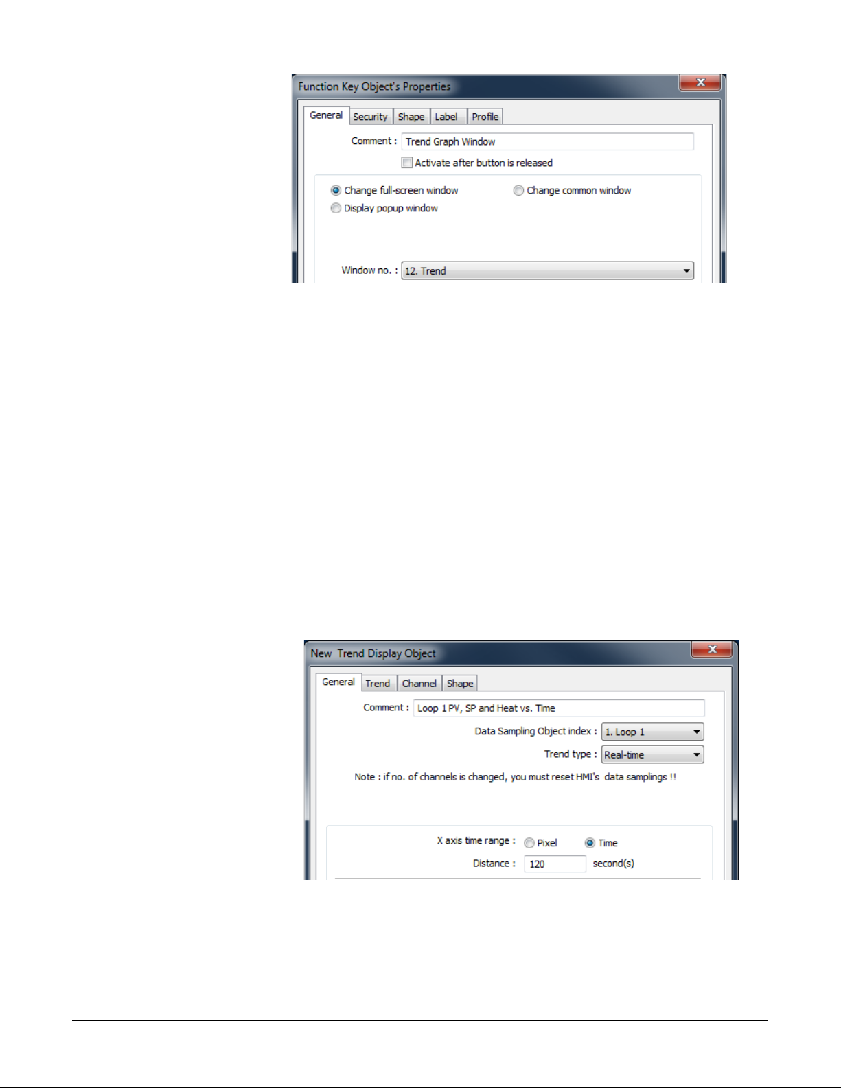
7) Edit the Comment to
read Trend Graph
(066)
1) On the Objects menu
Window.
8) Choose Change fullscreen window.
9) For Window no.
choose 12. Trend.
10) Click the Label tab.
11) Edit the Content to read Trend.
12) Click OK to close the Function Key Object’s Properties window.
13) If necessary, select the function key by clicking it.
14) From the Edit menu, choose Copy.
15) Select window 12 Trend.
16) From the Edit menu, choose Paste.
17) Position the button centered at the bottom of the screen.
18) Edit the new button’s properties so that it changes to full-screen window 10 Initial and is
labeled “Back”.
To create a trend graph:
point to Data Logging
and choose Trend
Display.
2) In Comment type a
description of the trend
such as “Loop 1 PV,
SP and Heat vs. Time”.
3) For Data Sampling
Object index choose
the data sampling
object you previously
configured.
(051)
Silver Series EM OIT 38 Watlow Addendum
Page 39

4) For Trend type choose Real-time.
5) For Distance between data samples/X axis time range choose Time.
7) Click the Trend tab.
9) Click the Channel tab.
6) In Distance type the number of seconds the width of the trend graph will represent. For
example, if you want to see two minutes of data at once, type 120.
8) Choose a Frame color
and a Background
color.
10) For each channel to be
graphed:
• In the Data sampling
object group check
Display.
• For Color choose a
color that contrasts with
the background color.
(052)
• In Zero type the value
that should be graphed
at the bottom of the yaxis.
• In Span type the value
that should be graphed
at the top of the y-axis.
11) Click OK.
(076)
Note: Keep in mind that while you can choose a different zero and
span for each pen, you don’t want to confuse users, so it may be best
to graph all the channels against the same zero an span values.
Silver Series EM OIT 39 Watlow Addendum
Page 40

12) Place and size the trend
object.
13) Optional: In the Trend
14) Optional: Use the
Display Object
Properties dialog
Trend tab enable the
Grid and set it up to
display the time.
(053)
Scale tool to add a
scale and labels with
the Text tool. Color
coordinate these or add
a legend if the trend
channels don’t all have
the same zero and
span.
(054)
(055)
Silver Series EM OIT 40 Watlow Addendum
Page 41

Use Recipes
RMC
RMH
PM
ST
ST GTW*
Closed Loop Set Point
2501
5221
2161
22
2161 2 0
Alarm High Set Point
1741
2661
1481
98
1481 2 2
Heat Proportional Band
2231
4111
1891
233
1897 2 4
Integral
2235
4115
1895
227
1891 2 6
Derivative
2237
4117
1897
229
1893 2 8
This example assumes you have a project with at least one controller in which the recipe memory has
not already been used for something else.
In this example we will create a recipe that has five parameters from one controller. For each parameter
we will create a data transfer object that saves the parameter’s value in the recipe in the OIT. For these
objects the source addresses are the parameters’ Modbus addresses in the controller and the destination
addresses are RW (recipe word) addresses in the OIT. See the table.
Note: This example uses specific addresses internal to the OIT. If you have used one or more of these
for other purposes you will have to choose appropriate addresses for your project.
To create a recipe window and link it to the other screens:
1) Create and open a window to use for viewing, saving and loading recipes called “Recipe
Manager”.
2) Create a button on WINDOW 10 that opens the Recipe Manager window.
3) Create a button on the Recipe Manager window that opens window 10 Initial.
Note: Refer to the Trend example if necessary.
Repeat the following steps to add a data transfer object to the Recipe Manager screen for each
parameter you want to save in a recipe. Refer to the table below for addresses etc.:
“Destination”
Recipe
Address
Parameter
*ST via RUI Gateway
“Source” Address in Controller
Size in
Words
Silver Series EM OIT 41 Watlow Addendum
Page 42
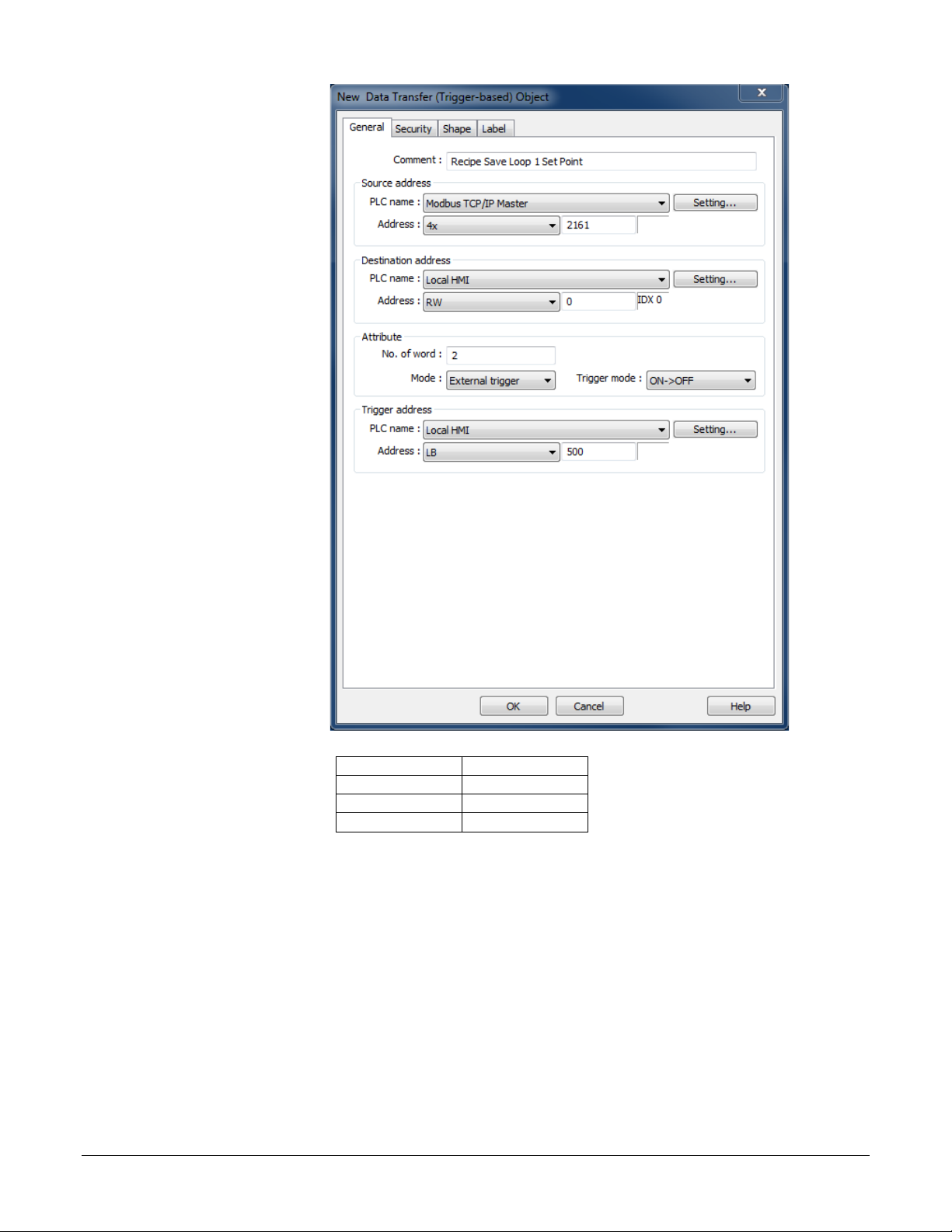
1) From the Objects
menu choose Data
Data Type
No. of words
Float
2
16-bit integer
1
32-bit integer
2
Transfer (Triggerbased).
2) In Comment type
“Recipe Save:” and
the name of the name
of the parameter
(such as “Loop 1 Set
Point”.
3) For Source address
PLC name choose
Modbus RTU Master
or Modbus TCP/IP
Master.
4) For Source address
choose 4x and enter
the address of the
parameter.
5) In No. of words type
word size of the
parameter’s data
type. See Table.
6) Click Setting…
7) For Destination
address PLC name
choose the OIT
(060)
(Local HMI by
default).
8) For Destination address Device type choose RW to store recipes in the battery backed up
recipe word memory.
9) In Destination address Address type 0 for the first item in the recipe (Increment this by the
previous item’s No of words for each subsequent recipe item. For example, if the first item was
a 16-bit integer, the address of the second item is 1. If the second item is a float, the address of
the third item is 3.)
10) If you want to store more than one recipe:
• Check Destination address Index register.
• For Destination address Index choose INDEX 0 (16-bit).
Silver Series EM OIT 42 Watlow Addendum
Page 43

11) Click OK to close the Address dialog
Address
RMC
RMH
PM
ST
ST GTW*
Closed Loop Set Point
0
2
2501
5221
2161
22
2161
Alarm High Set Point
2
2
1741
2661
1481
98
1481
Heat Proportional Band
4
2
2231
4111
1891
233
1897
Integral 6 2
2235
4115
1895
227
1891
Derivative
8
2
2237
4117
1897
229
1893
12) For Mode choose External Trigger.
13) For Trigger address PLC name choose the OIT (Local HMI by default).
14) For Trigger address Device type choose LB to use an internal bit to cause the OIT to store
values in a recipe.
15) In Trigger address Address type 500.
16) Click the Label tab.
17) Check Use label.
18) Set State to 0.
19) In Content type the name of the parameter.
20) Click OK.
21) Place the Data Transfer (Trigger-based) object on the screen.
Repeat the following steps to create the data transfer items that will load recipes in to the
controller:
Note: For the data transfer objects that load the recipe from the OIT to the controller, the source
addresses are RW (recipe words) addresses in the OIT and the destination addresses are the parameters’
Modbus addresses in the controller.
Parameter
*ST via RUI Gateway
“Source”
Recipe
Size in
Words
“Destination” Address in Controller
Silver Series EM OIT 43 Watlow Addendum
Page 44

1) From the Objects
menu choose Data
Transfer (Triggerbased).
2) In Description type
“Recipe Load:” and
the name of the
parameter (such as
“Loop 1 Set Point”).
3) For Source address
PLC name choose
the OIT.
4) For Source address
choose RW and type
the recipe address for
the item.
5) If you set up the recipe save to use and index register:
• Click Source address Settings…
(062)
• Check Source address Index register
• For Source address Index choose INDEX 0 (16-bit).
• Click OK to close the Address dialog.
6) In No. of words type word size of the parameter’s data type.
7) For Destination address PLC name choose Modbus RTU Master or Modbus TCP/IP Master.
8) In Destination address Address choose 4x and enter the controller address of the parameter.
9) For Mode choose External Trigger.
10) For Trigger address PLC name choose the OIT (Local HMI by default).
11) For Trigger address Device type choose LB to use an internal bit to cause the OIT to load
recipe values in to a controller.
12) In Trigger address Address type 501.
13) Click the Label tab.
14) Check Use label.
15) Enter the name of the parameter to display.
16) Click OK.
17) Place the Data Transfer (Trigger-based) object on the screen.
Silver Series EM OIT 44 Watlow Addendum
Page 45
To create a button to trigger the data transfer objects to copy the values currently in the
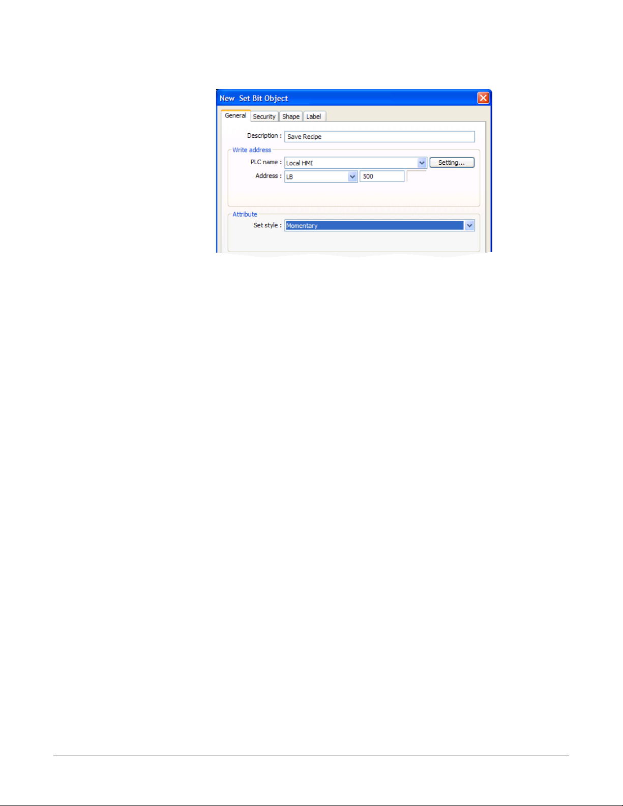
1) On the Objects
controller to the corresponding recipe memory in the OIT:
menu, point to
Button and choose
Set Bit.
2) In Description type
“Save Recipe”.
3) For PLC name
choose the OIT
(Local HMI by
default).
(063)
4) For Address choose
LB and type 500.
5) For Set style Choose Momentary.
6) Click the Label tab.
7) Check Use label.
8) In Content for state 0 type “Save to OIT”.
9) Click OK.
10) Place the button.
To create a button to trigger the data transfer objects to copy the values currently in the OIT ’s
recipe memory to the controller:
1) On the Objects menu, point to Button and choose Set Bit.
2) In Description type “Load Recipe”.
3) For PLC name choose the OIT (Local HMI by default).
4) For Address choose LB and type 501.
5) For Set style Choose Momentary.
6) Click the Label tab.
7) Check Use label.
8) In Content for state 0 type “Load from OIT”.
9) Click OK.
10) Place the button.
Note: Using pictures for buttons may help operators.
Silver Series EM OIT 45 Watlow Addendum
Page 46
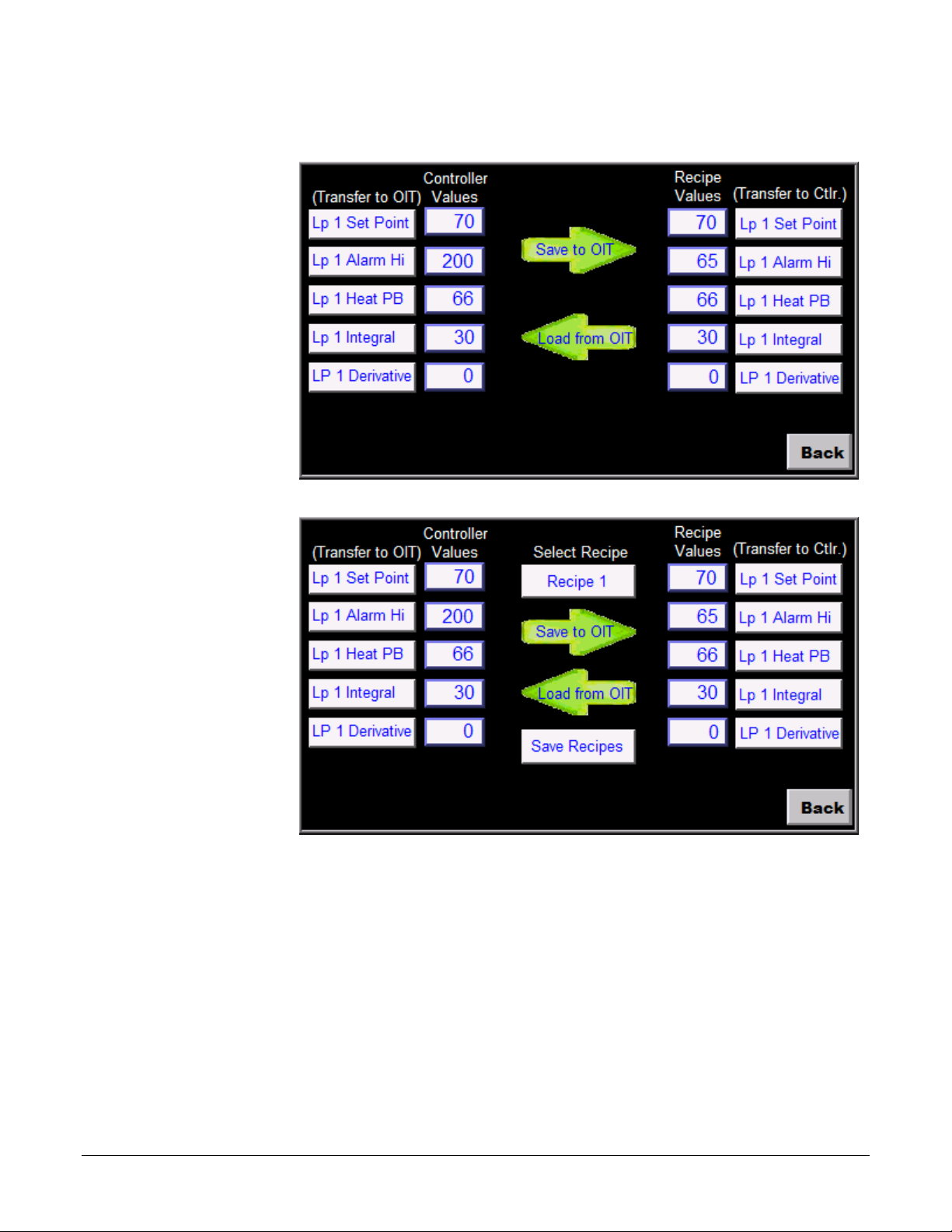
Optional: To see what you are copying from the controller to the OIT’s recipe memory, create an
Optional: To see or edit
Optional: The values in
object displaying the current value in the controller next to each Data Transfer (Trigger-based)
object. Create a label that indicates what the fields are such as “Current Controller Values”.
directly what is saved in
recipe memory create a
data entry object for each
recipe item. These objects
should display the values
of the data in the RW
memory at the recipe
addresses. Create a label
that indicates what the
fields are such as “Recipe
Values”.
the RW addresses are
automatically saved in
non-volatile memory
every five minutes, but
adding a button that
momentarily sets LB9029 forces the values to
be saved and can avoid
lost data in the event the
power is shut off too soon
after editing a recipe.
Optional: If you want to
store more than one recipe
in the OIT, set up the data
transfer objects to use
indexing for the RW
addresses.
(068)
(071)
Silver Series EM OIT 46 Watlow Addendum
Page 47
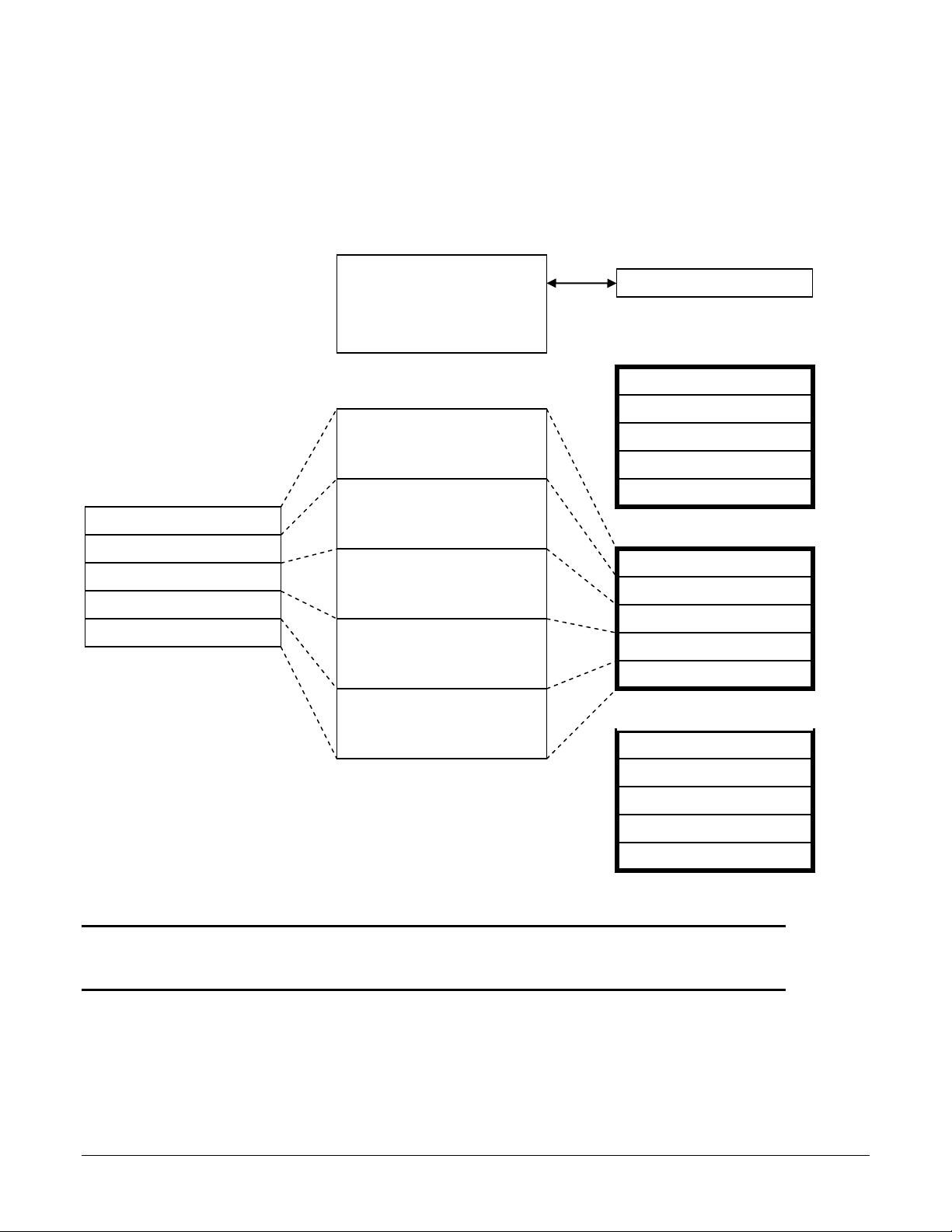
Address indexing allows a screen object to display and set the value of different memory locations
Data Transfer Object 1
Data Transfer Object 2
Data Transfer Object 3
Data Transfer Objects
Data Transfer Object 4
Data Transfer Object 5
RW 0: (Lp 1 Set Point)
RW 2: (Lp 1 Hi Alarm)
RW 4: (Lp 1 Heat PB)
RW 6: (Lp 1 Integral)
RW 8: (Lp 1 Derivative)
RW 10: (Lp 1 Set Point)
RW 12: (Lp 1 Hi Alarm)
RW 14: (Lp 1 Heat PB)
RW 16: (Lp 1 Integral)
RW 18: (Lp 1 Derivative)
RW Memory
Recipe 2 (index = 10)
RW 20: (Lp 1 Set Point)
RW 22: (Lp 1 Hi Alarm)
RW 24: (Lp 1 Heat PB)
RW 26: (Lp 1 Integral)
RW 28: (Lp 1 Derivative)
Recipe 3 (index = 20)
Multi-State Switch
LW Memory
LW 9200: address index
2161: (Lp 1 Set Point)
1481: (Lp 1 Hi Alarm)
1891: (Lp 1 Heat PB)
1895: (Lp 1 Integral)
1897: (Lp 1 Derivative)
Controller Memory
Recipe 1 (index = 0)
Recipe Selector
depending on the value in the index. In this example we use LW-9200 as the address index. Whatever
value the index is set to is added to the address in the data transfer (and recipe display) objects. When
the index value is zero, the first recipe is used. When the index is 10 the second recipe is used. When the
index is 20 the third recipe is used. A multi-state switch is used to set the value of the index when the
user selects the recipe.
Address = LW 9200
“Recipe 1” = State 0 = 0
“Recipe 2” = State 1 = 10
(Lp 1 Set Point)
Address = RW 0 + index
(Lp 1 Hi Alarm)
Address = RW 2 + index
(Lp 1 Heat PB)
Address = RW 4 + index
(Lp 1 Integral)
Address = RW 6 + index
(Lp 1 Derivative)
Address = RW 8 + index
Note: You can also use the address index to create one screen that displays data for
one loop at a time with a multi-state switch or option list that allow users to switch
from one loop to another.
Silver Series EM OIT 47 Watlow Addendum
Page 48

To select the recipe to save to or load from create a multi-state switch to select the recipe as
1) On the Objects
follows:
menu point to
Buttons and
choose MultiState Switch.
2) In Description
type “Recipe
Selector”.
3) Click Read
address Setting…
4) For PLC name
choose the OIT
(Local HMI by
default).
5) Check System tag.
6) For Device type
choose LW-9200
(16bit) : address
index 0.
7) Click OK to close
the Address
dialog.
8) Click Write
address Setting…
9) For PLC name
choose the OIT
(Local HMI by
default).
10) Check System tag.
11) For Device type choose LW-9200 (16bit) : address index 0.
12) Click OK to close the Address dialog.
13) For Switch style choose JOG+.
14) For No. of states choose the number of recipes you want to store.
15) For Cyclical choose Enable.
16) Check User-defined mapping.
(069)
Silver Series EM OIT 48 Watlow Addendum
Page 49

17) Click Setting…
18) For each state enter
the appropriate offset
Value. For state 0
enter 0. For state 1
enter a value that will
offset the beginning
of the second recipe
beyond the end of the
first in the recipe
memory.
19) Click OK to close
the Mapping
window.
20) Click the Label tab.
21) Check Use label.
(070)
Note: The first recipe is selected with the multi-state switch in its state
0. This recipe stores its values in the memory locations you entered in
the data transfer objects with no offset from address indexing, so for
state 0 the Value is 0. Calculate the minimum offset for the second
recipe by finding the sum of the number of words in memory used to
store the items in one recipe. The second recipe (state 1 for the multistate switch) should set the offset to this sum. The third recipe (state 2)
should set the offset to twice the sum. The fourth recipe (state 3)
should set the offset to three times the sum. And so on.
22) In Content enter a label indicating which recipe is selected. (For state 0 type “Recipe 1”, for
state 1 type “Recipe 2” etc.)
23) Click OK and place the Multi-State Switch object on the screen.
To create a button to save the recipes in non-volitile memory:
1) On the Objects menu point to Buttons and choose Set Bit.
2) In Comment type “Save Recipes”.
3) Click Write address Setting…
4) For PLC name choose the OIT (Local HMI by default).
5) Check System tag.
6) For Device type choose LB-9029 : save all recipe data to machine (set ON).
7) Click OK to close the Address dialog.
8) For Set style choose Momentary.
9) Click the Label tab.
10) Check Use label.
11) In Content enter, “Save Recipes”.
12) Click OK and place the Set Bit object on the screen.
Silver Series EM OIT 49 Watlow Addendum
Page 50

Silver Series EM OIT 50 Watlow Addendum
 Loading...