

Page 1

Data Communications with the Watlow
Series 988 Family of Controllers
User’s Manual
Includes:
981-984 Ramping
986-989 Temperature or Process
996-999 Dual Channel
W
A
TL
W
PROCESS
[`982]
L1 L2 L3 L4
DEV
% OUT
SERIES 982
DISPLAY
HOLD
RUN
MODE
SERIES 988
User Level Targeted:
• New User............................. Go to page 1.1
• Experienced User ................Go to page 2.1
• Expert User .........Go to page 5.1, 6.1 or 7.1
Installer:
• Wiring and installation.........Go to page 2.1
• Setup...................................Go to page 3.1
A
TL
W
PROCESS
[`988]
L1 L2 L3 L4
DEV
% OUT
DISPLAY
AUTO
MAN
MODE
W
W
PROCESS
W
A
TL
[`998]
1A 2A 1B 2B
CH A
CH B
SERIES 998
DISPLAY
AUTO
MAN
MODE
Watlow Controls
1241 Bundy Blvd., P.O. Box 5580, Winona, Minnesota 55987-5580; Phone: (507) 454-5300;
0600-0009-0004 Rev B
Supersedes: W98F-XUMN Rev A03
February 1998
Fax: (507) 452-4507
97
TOTAL
CUSTOMER
SATISFACTION
ISO 9001
Registered Company
Winona, Minnesota USA
$15.00
Made in the U.S.A.
Printed on Recycled Paper, 10% Post-consumer Waste.
Page 2

About This Manual
How to Use this Manual
We have designed this user’s manual to be a helpful guide to your new Watlow
controller. The headlines in the upper right and left corners indicate which tasks are
explained on that page. If you are a new user, we suggest that your read the first
four chapters of this manual.
Notes, Cautions and Warnings
We use notes, cautions and warnings throughout this book to draw your attention
to important operational and safety information.
A bold text “NOTE” marks a short message in the margin to alert you to an important detail.
A bold text “CAUTION” safety alert appears with information that is important for
protecting your equipment and performance. Be especially careful to read and
follow all cautions that apply to your application.
A bold text “WARNING” safety alert appears with information that is important for
protecting you, others and equipment from damage. Pay very close attention to
all warnings that apply to your application.
The ç symbol (an exclamation point in a triangle) precedes a general CAUTION
or WARNING statement.
The Ó symbol (a lightning bolt in a triangle) precedes an electric shock hazard
CAUTION or WARNING safety statement.
Technical Assistance
If you encounter a problem with your Watlow controller, review all of your configuration information for each step of the setup, to verify that your selections are
consistent with your applications.
If the problem persists after checking all the steps, call for technical assistance:
Watlow Controls, (507) 454-5300, between 7:00 a.m. and 5:00 p.m. Central
Standard Time. Ask for an applications engineer. When you call, have the following
information ready:
• the controller’s model number (the 12-digit number is printed on the top of the
stickers on each side of the controller case and on the right hand or top circuit
board);
• this user’s manual;
• all configuration information;
• the Diagnostics Menu readings.
Comments and Suggestions
We welcome your comments and opinions about this user’s manual and the Series
988 family of controllers. Send them to the Technical Editor, Watlow Controls, 1241
Bundy Boulevard, P.O. Box 5580, Winona, MN 55987-5580. Or call (507) 4545300 or fax them to (507) 452-4507.
Warranty and Returns
For information about the warranty covering the Series 988 family of controllers
see the Appendix.
The Data Communications User’s Manual for the Series 988 family is copyrighted
by Watlow Controls, Inc., © 1997, with all rights reserved. (1385)
Page 3

Table of Contents
Data Communications with the Watlow Series 988 Family of Controllers
Chapter 1
Introduction to Data Communications
1.1 Machine-to-Machine Communication
1.1 Protocol
1.1 A Protocol Example
1.3 EIA-232, EIA-485 and EIA-422 Interfaces
1.4 ASCII
1.4 Parity Bit
1.5 Start and Stop Bits
1.5 Baud Rate
1.5 Computer Languages
1.5 Syntax
1.6 ASCII Control Character Definitions
1.6 Data Communications Conversation
Chapter 2
Hardware and Wiring
2.1 Serial Hardware Interfaces
2.1 Your Computer’s Serial Interface
2.2 Communications Wiring
2.2 EIA-232 Interface Wiring
2.3 EIA-485 Interface Wiring
2.4 EIA-422 Interface Wiring
Chapter 3
Communications Setup
3.1 Connecting the Controller and Computer
3.1 Software Protocols and Device Addresses
3.1 Communications Software
3.2 Setup at the Controller's Front Panel
Chapter 4
Sending Commands
4.1 General Message Syntax
4.1 Message Syntax
4.1 Data Rules
4.1 Command List
4.2 Example Format
4.2 XON/XOFF Protocol for EIA-232
4.2 How to Communicate Using XON/XOFF
4.3 How to Communicate Using ANSI X3.28
4.4 Device Addresses
4.5 ANSI X3.28 Protocol Example
4.6 Modbus RTU
4.10 Cyclical Redundancy Checksum (CRC)
Algorithm
Chapter 5
Command Summary of the Series 981-984
5.1 Complete Parameter Download Sequence
5.2 Run/Hold Mode and Prompt Accessibility
5.3 Ramping Controller Prompt Table
5.12 Ramping Controller MTR Command
5.13 Ramping Controller STP Command
5.14 Ramping Controller Commands Table
5.16 982 Modbus RTU Address Table
Chapter 6
Command Summary of the Series 986-989
6.1 Complete Parameter Download Sequence
6.2 Temperature/process Controller Prompt Table
6.13 988 Modbus RTU Address Table
Chapter 7
Command Summary of the Series 996-999
7.1 Complete Parameter Download Sequence
7.2 Dual Channel Controller Prompt Table
7.12 998 Modbus RTU Address Table
Appendix
A.1 Handling Communications Error Codes
A.1 User Responsibility
A.2 ASCII Characters
A.3 Index
Table of Contents Data Communications with the Watlow Series 988 Family of Controllers
III
Page 4

Table of Contents
NOTES
IV
Table of ContentsData Communications with the Watlow Series 988 Family of Controllers
Page 5

Chapter 1 Introduction to Data Communications
Machine-to-Machine Communication
Humans use basic components to exchange messages. Computers and controllers
also use certain elements in order to communicate: a character set; a common
NOTE:
This manual applies
only to controllers
with the data
communications
option (9___-_____R__ or 9___-_____S__ or 9___-_____U__). Please use it
in conjunction with
the user's manuals.
data link, or interface; and a protocol, to prevent confusion and errors.
Serial communication is the exchange of data one bit at a time on a single data
line or channel. Serial contrasts with "parallel" communication, which sends several
bits of information simultaneously over multiple lines or channels. Not only is serial
data communication typically simpler than parallel, it generally costs less.
Computers need a connecting interface over which to communicate. They may
use one pair of wires to send information in one direction and another pair to send
in the opposite direction (full duplex). Or, they may use one pair to send in both
directions (half duplex).
Bit is simply the contraction of "binary digit," either a "1" or a "0." A byte is a string
of seven or eight bits, which a computer treats as a single "character." The ASCII
(pronounced "asky") character set uses a unique, seven-bit byte to represent each
letter, digit and punctuation mark.
Interfaces
Protocol
Now we need a few rules to "talk" by. Protocol determines who gets to talk when. A
protocol is a set of standards for formatting and timing information exchange
between electronic systems.
Protocol describes how to initiate an exchange. It also prevents two machines from
attempting to send data at the same time. There are a number of different data
communications protocols, just as there are different human cultural protocols that
vary according to the situation.
A Protocol Example
Let's assume that we have a computer and controllers linked together. They all use
ASCII and are connected via a common interface. In process control applications,
one device often has greater function and memory capability than the devices it is
communicating with. This "master" device always initiates exchanges between it
and the connected "remote" devices.
Here's what happens: Imagine "PC-1," the master computer, sitting at the end of a
long hallway with nine doors in it. Each door has a remote device behind it. PC-1
has a telephone line to all the devices. The remote devices are busy controlling
heaters to specific set points. PC-1 monitors and changes the instructions that
each remote device uses to control its heaters.
Introduction to Data Communications, Chapter 1 Data Communications with the Watlow Series 988 Family
1.1
Page 6

Interfaces
By your request PC-1 wants to talk with device "D-2" to change a set point. PC-1
must first identify D-2 on the line and inquire whether D-2 has time to talk. This
electronic knocking on D-2's door is the "connection."
One of three scenarios may occur when PC-1 calls:
1) D-2 answers saying, "This is D-2, go ahead," and PC-1 begins to talk.
2) D-2 answers and says, "I'm too busy to talk now. Wait until I tell you I'm
finished."
3) D-2 does not answer, which indicates a possible system malfunction.
Let's take the best-case scenario. Here is a simple version of what happens: D-2
answers and hears PC-1 say, "Hello, D-2. Do you have time to talk?"
D-2 acknowledges PC-1 with a "D-2 here, go ahead."
PC-1 then sends an ASCII-encoded message instructing D-2 to change a set point
to 1,000°F. (message)
When PC-1 is finished with its message, it says in effect, "That's all, your turn."
D-2 replies, "OK," and carries out the instruction. D-2 then takes the protocol lead,
and tells PC-1, "The new set point is 1,000°F." (message)
PC-1 says, "OK."
D-2 says, "That's all, your turn."
PC-1 then takes the protocol lead and says, "Thank you, that's all."
D-2 hangs up. (disconnect)
That's basically how the connect, message and disconnect protocols work in
Watlow data communications.
The hallway in this example is really a communications bus — a common connec-
tion among a number of separate devices. A communications system with multiple
devices on a common bus is called a multidrop system.
The exact connect-message-disconnect procedure assures that you are talking to
the correct device.
Protocol maintains system integrity by requiring a response to each message. It's
like registered mail — you know that your letter has been received because the
post office sends you a signed receipt.
In Watlow data communications, a dialog will continue successfully as long as the
messages are in the correct form and responses are returned to the protocol
leader. If the operator enters an incorrect message, or interference comes on to the
data line, there will be no response. In that case the operator or the master must
retransmit the message or go to a recovery procedure. If an operator continues to
enter an incorrect message or interference continues on the data line, the system
will halt until the problem is resolved.
1.2
Data Communications with the Watlow Series 988 Family
Introduction to Data Communications, Chapter 1
Page 7
Interfaces
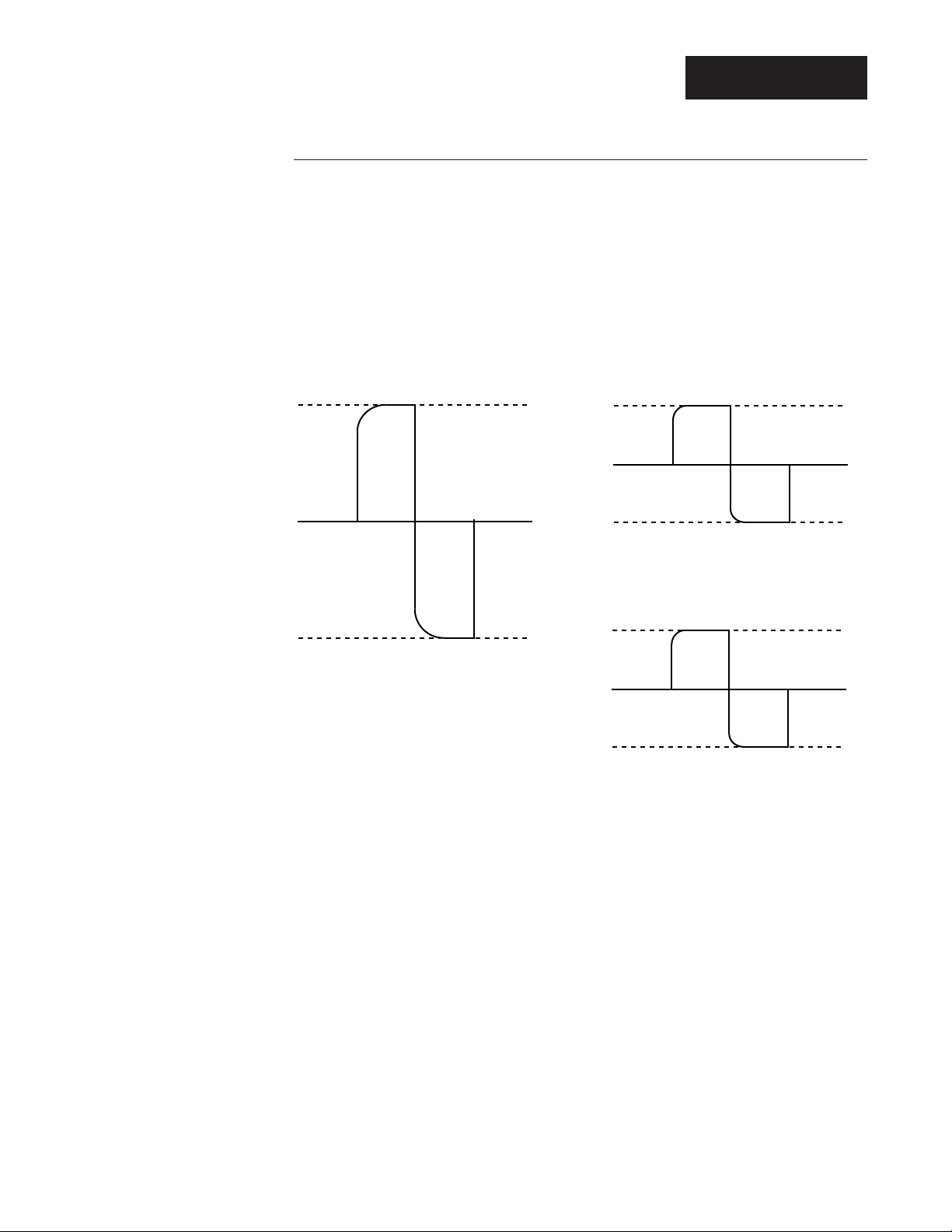
EIA-232, EIA-485 and EIA-422 Interfaces
The three interfaces we're concerned with on this controller are EIA-232, EIA-485
and EIA-422.
An EIA-232 interface uses three wires: a single transmit wire; a single receive wire;
and a common line. Only two devices can use an EIA-232 interface. A -12 volt
signal indicates a 1 and a +12 volt signal indicates a 0. The EIA-232 signal is
referenced to the common line rather than to a separate wire, as in EIA-485 and
EIA-422. An EIA-232 cable is limited to 50 feet, due to noise susceptibility.
Figure 1.3 - Interface
bit signals.
0 bit
1 bit
Bit signals on an EIA-232 interface.
+12V
0 bit
1 bit
0V
Bit signals on an EIA-485 interface.
-12V
0 bit
1 bit
Bit signals on an EIA-422 interface.
+5V
-5V
+5V
-5V
An EIA-485 interface uses three wires: a T+/R+; a T-/R-; and a common line. A
-5-volt signal is interpreted as a 1, a +5-volt signal as a 0. Up to 32 remote devices
can be connected to a master on a multi-drop network up to 4,000 feet long.
0V
0V
The EIA-422 interface uses five wires: a "talk" pair; a "listen" pair; and a common
line. It can handle one master and up to ten remote devices in a multidrop network
up to 4,000 feet long. EIA-422 uses the difference in voltage between the two wires
to indicate a 1 or a 0 bit. A 1 is a difference of -5 volts, while a 0 is a difference of
+5 volts.
Of these three interfaces, EIA-485 has the lowest impedance, a multiple-device
capability, greatest noise immunity and the longest distance capability — up to
4,000 feet of total network cable length.
Introduction to Data Communications, Chapter 1 Data Communications with the Watlow Series 988 Family
1.3
Page 8

ASCII
Table 1.4 - Comparing Interfaces.
Maximum Maximum Cable
Net Length Controllers Type
EIA-232 50 feet 1 3-wire
EIA-485 4,000 feet 32 3-wire
EIA-422 4,000 feet 10 5-wire
NOTE:
The Modbus feature
on the Series 988
controllers allows up
to 247 controllers to
share one EIA-485
network, by using
network bridges.
See Chapter 6 for
more information on
Modbus.
ASCII
The ASCII code defines 128 separate 7-bit characters — one for each letter, digit
and punctuation mark. ASCII also includes control characters similar to those we
find on computer keys, like "backspace," "shift" and "return." It also has ten communications control characters for "identification," "enquiry" (inquiry), "start of text,"
"end of text," "end of transmission," "acknowledge," "negative acknowledge" and
"escape."
The ASCII code is sometimes written in a base-16 number system, called hexadecimal or "hex" for short. The first ten digits of this system are represented by the
numbers 0 through 9, and the final six digits are represented by the letters A
through F. The 128 ASCII character code with the decimal and hexadecimal
equivalents is listed in the Appendix.
Parity Bit
Remember that ASCII is a seven- or eight-bit code. What about that eighth bit? It's
called the "parity" bit. A parity bit is added to the ASCII character to verify the
accuracy of the first seven bits. Here's how: We are declaring that the number of 1s
in the 8-bit character frame will be either always odd or always even. To do that,
about half the time we'll have to add another 1 to get an odd or an even number of
ones. The other half of the time we'll need to add a 0 so we don't change the total
number of 1s.
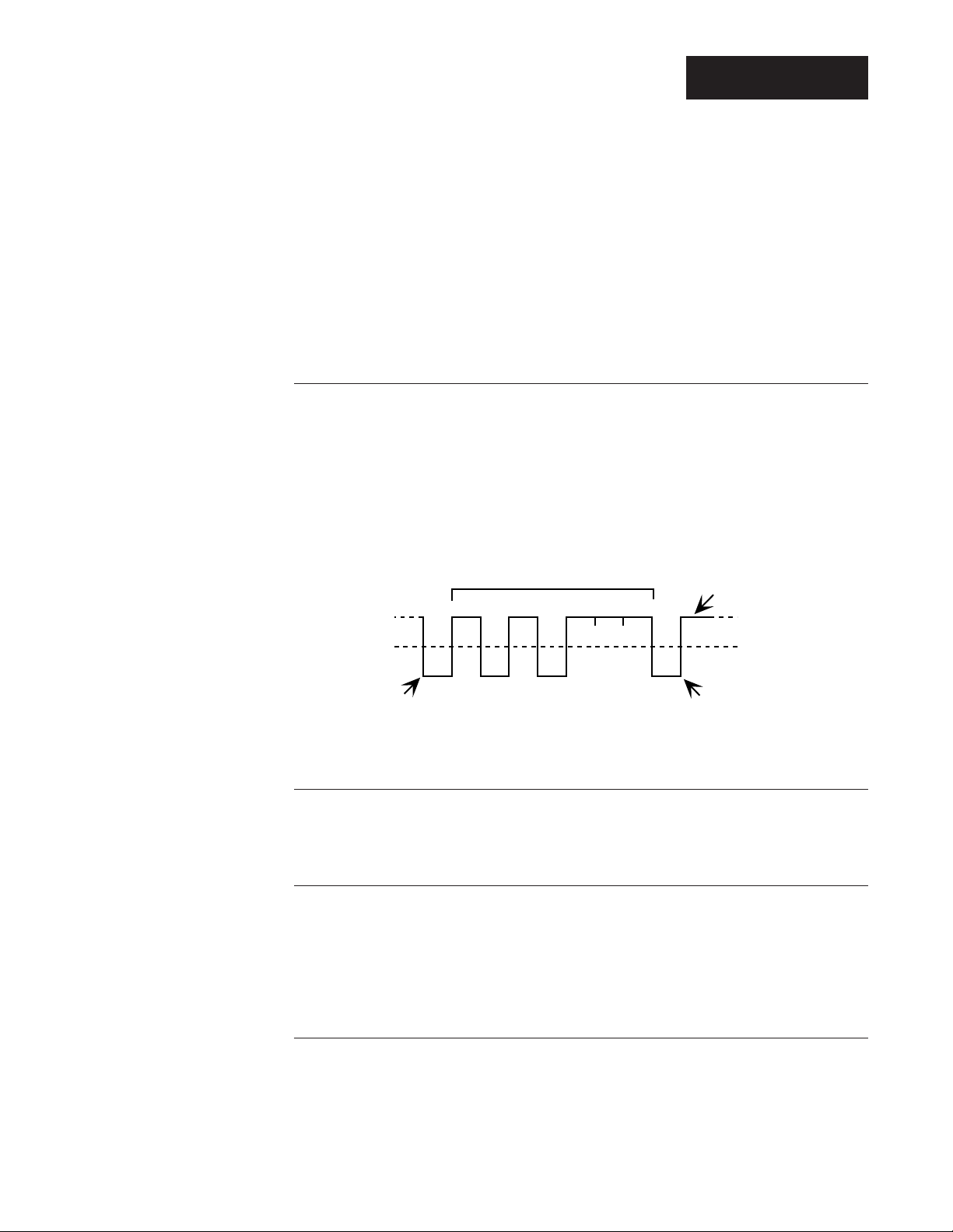
This way we can detect a single error in the seven-bit group. Take a look at the
representation of the transmitted upper case "W." In this case we have selected
"odd" parity. The number of 1s in the first seven bits, plus the parity bit, must
always total an odd number. The total number of 1s in the binary character
1010111 (W) is 5, already an odd number. Thus our parity bit will be a 0.
Figure 1.4 - ASCII
upper case "W"
(1010111).
1.4
Data Communications with the Watlow Series 988 Family
If we were transmitting the lower case "w" (binary 1110111), the parity bit would be
a 1 because the total number of 1's in the character frame is 6, an even number.
Adding the parity bit makes it odd, and consistent with the odd parity rule.
If a noise spike came onto the data line and changed the signal voltage level
enough to reverse a 1 to a 0 in the character frame, the receiver would detect that
7-bit character
+V
-V
bit position: 12345678
0
1
odd parity bit
Introduction to Data Communications, Chapter 1
Page 9
ASCII
error. The total number of 1s would be even and a violation of the odd-parity rule.
At Watlow, we use odd, even and no parity.
Odd parity sets the parity bit to 0 if there are an odd number of 1s in the first seven
bits.
Even parity sets the parity bit to 0 if there are an even number of 1s in the first
seven bits.
No parity ignores the parity bit.
Start and Stop Bits
A "start" bit informs the receiving device that a character is coming, and a "stop" bit
tells it that one is complete. The start bit is always a 0. The stop bit is always a 1.
We've added the start and stop bits to the transmitted "W" example.
The human speaking equivalent of these bits could be a clearing of the throat to
get someone's attention (start bit); and a pause at the end of a phrase (stop bit).
Both help the listener understand the message.
Figure 1.5 - ASCII
upper case "W" with
start and stop bits.
-V
+V
idle line
1
0
start bit
7-bit character
12345678
stop bit
odd parity bit
Baud Rate
The baud rate refers to the speed of data transmission. When a change in signal
represents one data bit, baud rate is equal to bits per second (bps). Our rates on
the 988 Family of controllers are 300, 600, 1200, 2400, 4800 and 9600 baud.
Computer Languages
Computer languages are simply sets of symbols and rules for their use. There are
many computer languages and a wide variety of applications for them. Programmers use languages to enable computers to do real work. We're providing a pilot
program written in Quick BASIC to demonstrate data communications with Watlow
controllers. You can download the MS-DOS™ version files ("comms4.zip" and
"comms4tm.zip" and com5set.exe) from the Watlow BBS, (507) 454-3958.
Syntax
Syntax for a natural language dictates how we put words together to make phrases
and sentences. In data communications, syntax also dictates how we order the
parts of a message.
Introduction to Data Communications, Chapter 1 Data Communications with the Watlow Series 988 Family
1.5
Page 10

Syntax
For example, the Series 986-989 parameter for set point information is SP1. The
controller's panel will normally display SP1 and set point information whenever you
physically press the DISPLAY key to reach SP1 in the parameter sequence. For a
computer linked to a controller, "SP1" is part of the syntax for data communications.
If you type just "SP1" on the computer keyboard, the controller won't respond to
your computer with the current set point 1 data. The syntax requires spaces and
"fields" of specific size to be complete.
Plus, we need to add the protocol. It's like putting a message in an envelope and
addressing it. The entire syntax of the SP1 command includes the message
protocol's STX (Start of Text) control character, SP1, space, up to four decimal
places of set-point data, and a protocol ETX (End of Text) control character.
The whole phrase would look like this:
<STX> SP1 0500 <ETX>
ASCII Control Character Definitions
ENQ Enquiry (inquiry): Request for a data link.
ACK Acknowledge: Affirmative response from the receiver.
NAK Negative Acknowledge: Negative response from the receiver.
STX Start of Text: Precedes any message from the sender.
ETX End of Text: Follows any message from the sender.
EOT End of Transmission: Tells the other device that it is its turn to send a mes-
sage.
DLE Data Link Escape: Disconnect signal from the master to devices on the
network.
A Data Communications Conversation
Now that you have a general grasp of the basic ideas and terms behind data
communications, we'll take the example further to see how an actual conversation
would take place.
The example on the next page follows the exchange between a computer (master)
and a controller (remote) as the computer sends a set point data command to the
controller.
1.6
That's really all there is to it. Remember — only the "master" may initiate exchanges and every message requires a response.
Data Communications with the Watlow Series 988 Family
Introduction to Data Communications, Chapter 1
Page 11

An Example of a Data Communication Conversation
Syntax
The computer (the master) initiates an
exchange with controller #2 (the remote).
The computer tells the controller to
change its set point.
The computer queries the controller for
the new set point.
computer
2 <ENQ> (#2, are you there?)
controller
2 <ACK> (I'm #2, I'm here.)
computer
<STX> = <space> SP1 <space> 500 <return> <ETX>
("Here comes a message."
"Make SP1 = 500°."
"I'm done with the message.")
controller
<ACK> ("I understand.")
computer
<STX> ? <space> SP1 <return> <ETX>
("Here comes a message."
"What is SP1 value?"
"I'm done with the message.")
controller
<ACK> ("I understand [the question].")
The controller confirms that the new set
point.
The computer ends the session.
computer
<EOT> ("That's all, go ahead.")
controller
<STX> 500 <ETX>
( "Here comes the answer."
"The value is 500°."
"I'm done with the answer.")
computer
<ACK> ("I understand [the answer].")
controller
<EOT> ("That's all, go ahead.")
computer
<DLE> <EOT> ("Disconnect, please. That's all."
[master waits])
Introduction to Data Communications, Chapter 1 Data Communications with the Watlow Series 988 Family
1.7
Page 12

Introduction
Notes
1.8
Data Communications with the Watlow Series 988 Family
Introduction to Data Communications, Chapter 1
Page 13

Chapter 2 Hardware and Wiring
Serial Hardware Interfaces
The Series 981-984, 986-989 and 996-999 controllers are factory-configured to
function in a broad variety of applications. The specifics of each controller's configuration is encoded in its model number. Depending on your unit's model number,
you have one of three hardware interfaces:
1) EIA-232 (9___-____-_R__) provides one-on-one communication with a maxi-
NOTE:
This manual applies
only to controllers
with the data
communications
option (9___-_____R__ or 9___-_____S__ or 9___-_____U__). Please use it
in conjunction with
the user's manuals.
mum network length of 50 feet connecting one controller to one computer.
2) EIA-485 (9___-____-_S__) provides a "multidrop" or multiple-device network
with up to 32 addresses with a 4,000-foot network length limit. EIA-422 provides a multidrop network for up to ten devices with a 4,000-foot network
length limit. To select the multidrop interface, enter the Setup Menu
[`SEt]. Use the up-arrow or down-arrow key to advance to the Communica-
tions Menu [COM]. Press the MODE key until the interface prompt [IntF]
appears. Select either 485 or 422.
3) EIA-232/EIA-485 (9___-____-_U__) If your controller is supplied with a "U"
board, you can select via the comms menu either EIA-232 or EIA-485 operation. The [IntF] parameter is defaulted to EIA-232. To select the multidrop
interface, enter the Setup Menu [`SEt]. Use the up-arrow or down-arrow key
to advance to the Communications Menu [COM]. Press the MODE key until
the interface prompt [IntF] appears. (Controllers equipped with the EIA-
232 interface do not require an interface selection.)
Hardware
Your Computer's Serial Interface
You can connect a data communication-equipped Series 981-984, 986-989 or 996999 to any computer with an EIA-422, EIA-232 or EIA-485 serial interface. A
personal computer with an EIA-232 serial output card, for instance, can talk to a
single EIA-232 equipped controller.
For a multiple-controller network with one personal computer, you'll need a converter to act as a bus, or multiple connection point.
For data communications serial interface converters for EIA-232 (RS-232), we
recommend either of these two suppliers:
• DATAFORTH Corp. (formerly supplied by Burr-Brown):
3331 E. Hemisphere Loop, Tuscon, AZ 85706
Tel: 1-800-444-7644, or (520) 741-1404 or Fax: (520) 741-0762
For EIA-422 (RS-422), part number: LDM 422
with a power supply and the correct 25 pin connector for your computer.
For EIA-485 (RS-485), part number: LDM 485
with a power supply and the correct 25 pin connector for your computer.
• B & B Electronics Manufacturing Company
707 Dayton Road, PO Box 1040, Ottawa, IL 61350
Tel: (815) 433-5100 or Fax: (815) 434-7094 or Web: http://www.bb-elec.com
For EIA-422/ EIA-485 (RS-422/ RS-485), part number: 485OIC
with a power supply and the correct 25 pin connector for your computer.
Hardware and Wiring, Chapter 2
Data Communications with the Watlow Series 988 Family
2.1
Page 14
Wiring
NOTE:
The Electronic
Industry Association
(EIA) RS-232
standard recommends a maximum
50-foot total pointto-point distance.
Communications Wiring
The rest of the chapter explains how to connect your controller to a computer.
Consult the instruction manual for your computer's serial port or serial card for
detailed serial port pin information. Industrial environments often contain a lot of
electrical noise. Take care to isolate your control system.
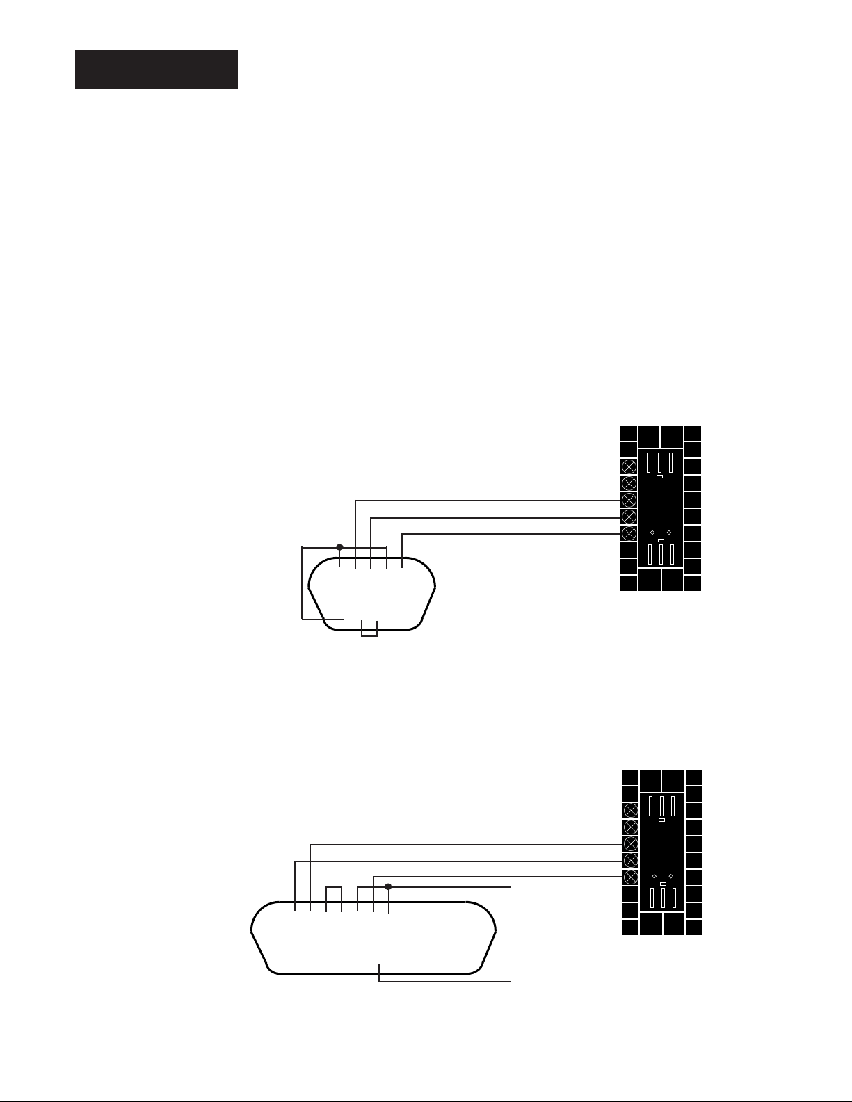
EIA-232 Interface Wiring
The EIA/-232 communications uses a three-wire, full-duplex system. There is a
separate line for transmitting data, a line for receiving data and a common line
between the computer and the controller. With EIA-232 you can have only one
controller connected to a single computer.
This diagram is a typical wiring example. The connections on the host computer
may vary, depending on the model. Refer to your computer or serial card user's
manual for specific information.
DB-9 Pinouts
1 DCD
2 receive
3 transmit
4 DTR
5 common
6 DSR
7 RTS
8 CTS
• • • • •
1 2 3 4 5
Transmit 5
Receive 6
Common 7
Figure 2.2 EIA-232 Interface
Wiring Diagrams.
6 7 8 9
• • • •
DB-9 female viewed from wire side
(typical connections with jumpers)
DB-25 Pinouts
2 transmit
3 receive
4 RTS
5 CTS
6 DSR
7 common
8 DCD
20 DTR
• • • • • • • • • • • • •
1 2 3 4 5 6 7 8 9 10 11 12 13
14 15 16 17 18 19 20 21 22 23 24 25
• • • • • • • • • • • •
DB-25 female viewed from wire side
(typical connections with jumpers)
Single Controller
Transmit 5
Receive 6
Common 7
Single Controller
2.2
Data Communications with the Watlow Series 988 Family
Hardware and Wiring, Chapter 2
Page 15
NOTE:
The Electronic
Industry Association
EIA-485 standard
recommends a
maximum total
network distance of
4,000 feet.
Wiring
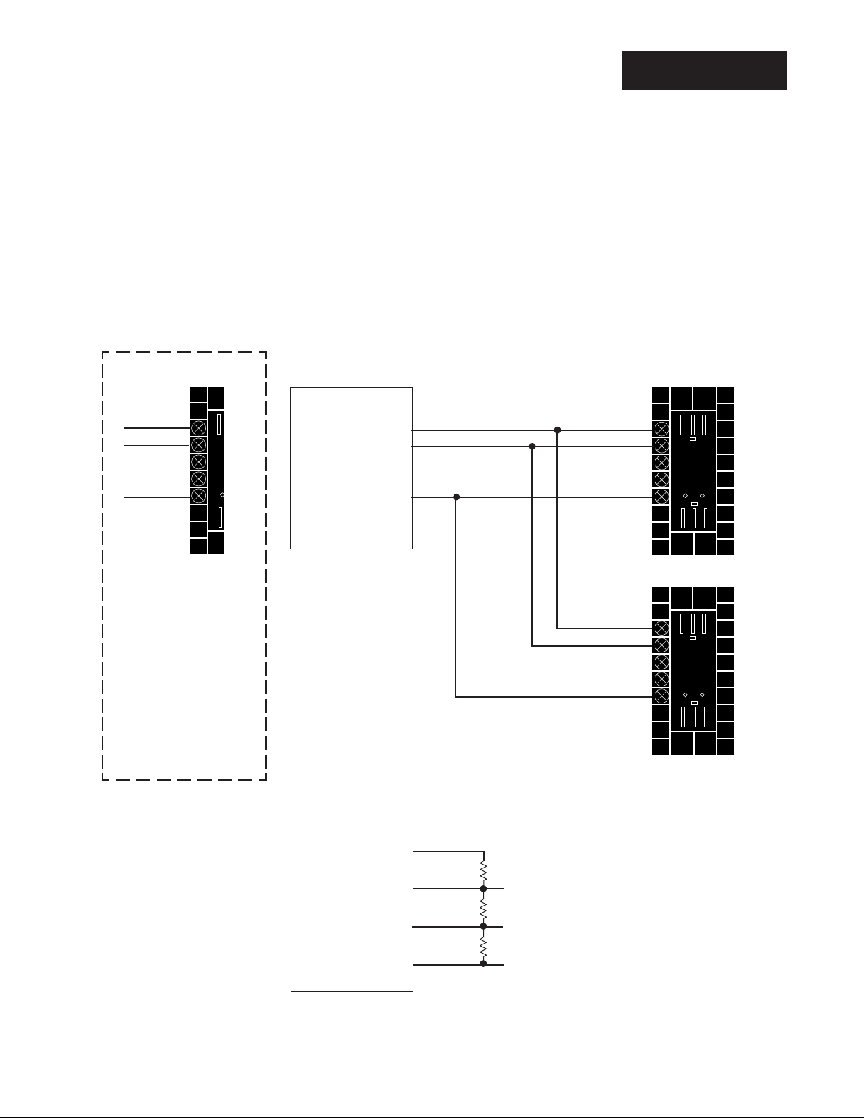
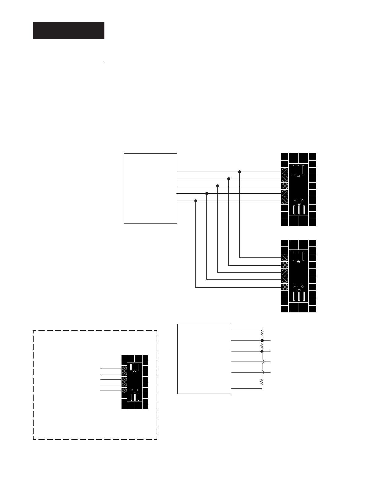
EIA-485 Interface Wiring
The EIA-485 communications uses a three-wire, half-duplex system. There are two
lines for transmitting and receiving and a common line. Only one device, the
computer or a controller, can be speaking at a time. The controller requires at
least a 7-millisecond delay between transmission and receipt of data. With
EIA-485 you can have from one to thirty-two controllers connected to a computer.
This diagram is a typical wiring example for units shipped after 1993 (see ç
Caution on this page). The connections on the host computer may vary, depending on the model. Refer to your computer user's manual for specific information.
As many as 32 units can be
connected to an EIA-485 network.
T-/R- 3
T+/R+ 4
Com 7
Controller
ç
CAUTION:
For older Series 986989 controllers with
a "date code" of
4693 or earlier,
terminal 3 is T-/R- (A)
and 4 is T+/R+ (B).
(See Diagnostics
Menu in the User's
Manual.)
B
A
Gnd
Converter Box or Card
T+/R+
T-/R-
Com
T+/R+ 3
T-/R- 4
Com 7
Controller #1
T+/R+ 3
T-/R- 4
Com 7
Controller #2
Figure 2.3 EIA-485 Interface
Wiring Diagrams.
Hardware and Wiring, Chapter 2
Converter box
or card
terminals with
termination,
pull-up and
pull-down
resistors.
+5V
Gnd
B
A
1KΩ
T+/R+
120Ω
T-/R-
1KΩ
Com
If the system does not work properly it
may need termination resistors at each
end of the network. A typical installation would require a 120-ohm resistor
across the transmit/receive terminals (3
and 4) of the last controller in the
network and the converter box or serial
card. Pull-up and pull-down resistors
may be needed to maintain the correct
voltage during the idle state.
Data Communications with the Watlow Series 988 Family
2.3
Page 16
Wiring
NOTE:
The Electronic
Industry Association
(EIA) RS-422
standard recommends a maximum
network distance of
4,000 feet.
EIA-422 Interface Wiring
The EIA-422 communications uses a five-wire, full-duplex system. There are two
separate lines for transmitting, two lines for receiving and a common line between
the computer and the controller. With EIA-422 you can connect from one to ten
controllers to a single computer.
This diagram is a typical wiring example for units shipped after 1993 (see ç
Caution on this page). The connections to the converter box or computer may
vary, depending on the model. Refer to the documentation for specific information.
B'
A'
Gnd
R+
RT+
B
T-
A
Com
T+ 3
T- 4
R+ 5
R- 6
Com 7
Figure 2.4 EIA-422 Interface
Wiring Diagrams.
ç
CAUTION:
For older Series
986-989 controllers with a "date
code" of 4693 or
earlier, terminal
3 is T-, 4 is T+, 5
is R- and 6 is
R+. (See Diagnostics Menu in
the User's
Manual.)
T- 3
T+ 4
R- 5
R+ 6
Com 7
Converter Box or Card
As many as 10 units
can be connected to
an EIA-422 network.
Controller
Controller #1
T+ 3
T- 4
R+ 5
R- 6
Com 7
Controller #2
Converter
box with
termination
pull-up and
pull-down
resistors.
RD
TD
+5V
B
A
B
A
Gnd
1KΩ
240Ω
1KΩ
If the system does not work properly it may need
termination resistors across the receive A and B terminals at the converter. A typical value would be 240Ω.
Pull-up and pull-down resistors may be needed to
maintain the correct voltage during the idle state.
2.4
Data Communications with the Watlow Series 988 Family
Hardware and Wiring, Chapter 2
Page 17

Chapter 3 Communications Setup
Connecting the Controller and the Computer
Remove power from both the controller and your computer before connecting them
together. Assemble a cable and the appropriate wiring at your computer. Refer to
the wiring in Chapter 2. As soon as you connect the data communications lines,
you may apply power to your system.
Software Protocols and Device Addresses
There are three communications protocols you may use. Depending on the type of
network you need, you must use the correct combination of interface and protocol.
Modbus works with all three interfaces.
To run a network with multiple devices Watlow uses the ANSI X3.28 Protocol
(based on ANSI X3.28 - 1976 Subcategories 2.2, and A.3) with the EIA-422 and
EIA-485 interface. ANSI X3.28 Protocol provides a response to every message. It
will also work with the EIA-232 interface, but you are limited to one controller and a
host computer.
Setup
To run a two-device network with an EIA-232 interface, you can also use XON/
XOFF Protocol, a simpler protocol. XON/XOFF will also work with the EIA-422 and
EIA-485 interface, but the network is limited to two devices — one computer
and one controller. XON/XOFF Protocol does not require a device to respond to
messages it receives.
To select the protocol, go to the Setup Menu [`SEt]; use the up-arrow or downarrow key to advance to the Communications Menu [COM]. Press the MODE key
until the protocol prompt [Prot] appears. Select either [FULL], for ANSI X3.28 2.2
- A.3, [``On] for XON/XOFF, or [Mod], for Modbus RTU.
If you are using ANSI X3.28 Protocol, choose an address number for each controller using the address prompt [Addr], which follows the protocol prompt [Prot].
This prompt will only appear if [Prot] is set to [FULL] or [Mod].
Communications Software
Watlow offers a Windows based configuration and monitoring software package for
the 988/989 controllers. We also offer a simple MS-DOS™ communications
demonstration program for the Series 981-984, 986-989, and 996-999. Ask your
Watlow field sales representative for a copy of the "Comm 4" program, or you can
download the files ("comms4.zip" and "comms4tm.zip" and com5set.exe) from the
Watlow BBS, (507) 454-3958.
Communications Setup, Chapter 3
Data Communications with the Watlow Series 988 Family
3.1
Page 18
Setup
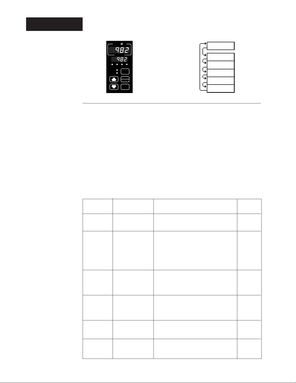
(
Figure 3.2 The Communications
Menu.
W
A
TL
W
PROCESS
L1 L2 L3 L4
DEV
DISPLAY
% OUT
HOLD
MODE
SERIES 988
RUN
Communications)
Baud rate
Data bits and parity
Protocol type
Address
Interface type
[COM]
(COM)
bAUd
[bAUd]
dAtA
[dAtA]
Prot
[Prot]
Addr
[Addr]
intF
[IntF]
( )
( )
( )
( )
( )
Setup at the Controller's Front Panel
• Press the < and > keys simultaneously for three seconds.
• The [SEt] prompt appears in the lower display.
• Press the < or > key until the [COM] prompt appears.
• Press the µ key to advance through the Communications Menu.
• Press the < or > key to select communications values from the table below.
NOTE:
Selecting [Mod]
automatically sets
[dAtA] to [``8n].
Table 3.2 Communications
Menu Prompts and
Descriptions.
• Document the setup parameters for each device on your network and label each
device.
• Press the ∂ key to exit.
Prompt Appears if… Range Factory
default
[bAUd] comms unit (Baud rate) [`300], [`600],
[1200], [2400], [4800], [9600] [9600]
[dAtA] comms unit [``7o] = 7 data bits, odd parity [``7o]
[``7E] = 7 data bits, even parity (see note)
[``8n] = 8 data bits, no parity
(Start bit = 1) (Fixed)
(Stop bit = 1) (Fixed)
[Prot] comms unit [FULL] = ANSI X3.28 2.2 - A.3 [FULL]
[``On] = XON / XOFF
[Mod] = Modbus
[Addr] [Prot] = [FULL] 0 to 31 (ASCII) if [IntF] = [`485] [```0]
or 0 to 9 (ASCII) if [IntF] = [`422] [```0]
[Prot] = [Mod] 1 to 247 if [IntF] = [Mod] [```1]
[IntF] "S" hardware [`485] = EIA-485 Interface type [`485]
[`422] = EIA-422 Interface type
[IntF] "U" hardware [`232] = EIA-232 Interface type [`232]
[`485] = EIA-485 Interface type
3.2
Data Communications with the Watlow Series 988 Family
Communications Setup, Chapter 3
Page 19

Chapter 4 Sending Commands
General Message Syntax
As soon as you link the devices, you can talk to the controllers using ASCII characters. They will respond to any Setup or Operation menu prompt, plus some others.
The controller will respond to either upper or lower case ASCII characters from
your computer.
Both protocol/interface combinations will respond to the general syntax if the
commands or queries are correctly transmitted. However, the ANSI X3.28 Protocol
requires beginning and ending characters, and the XON/XOFF protocol requires
ending characters.
Message Syntax
Messages from your computer to a controller must take this general form.
Command <space> data.1 <space> data.2 <space> data.3... data.N
"Command" is a character string. The brackets "<" and ">" enclose a non-literal
ç
CAUTION:
Avoid writing <=>
continuously, such
as ramping set
points or repetitive
loops, to the
controller's
EEPROM memory.
Continuous writes
may result in
premature control
failure, system
downtime and
damage to processes and equipment.
description. The space character, <space> or <sp>, is simply a delimiter, an ASCII
space character (hex 20). "Data fields" are prompts and values specific to the
command. The number of data fields depends on the particular command. The first
argument or parameter is abbreviated, "data.1," the next is "data.2," and so on.
In the syntax explanations that follow, we show you the specific arguments for each
command. It will speed the process if you remember this general syntax.
Data Rules
Data fields are prompts and values specific to particular commands. Specific data
for each command for each type of controller is listed after this chapter. These
rules govern their use:
• Data will include the characters 0 through 9; a decimal point if needed; or a
positive or negative sign.
• Data can include up to seven characters. A "+" or "-" sign, if used, must be first.
• Data can use leading zeros, up to the seven-character limit.
• The data.1 portion of message can be up to four total characters.
Sending Commands, Chapter 4
Command List
These commands, represented by their respective ASCII characters, will enable
you to program the controller from your computer. More detailed descriptions of the
commands are in Chapters 5, 6 and 7.
? Returns the value of a specific prompt from the controller.
= Sets a specific prompt in the controller to a specific value.
Data Communications with the Watlow Series 988 Family
4.1
Page 20

XON/XOFF
Example Format
This manual presents command examples in a consistent format. Information
bracketed by < > indicates a description, rather than literal characters. We show
each ASCII character that you must transmit to the controller, including space
between the characters. (A <space>, or <sp>, is itself an ASCII character, hex 20).
For instance, in the example below, you want to set the Alarm 2 Low [A2LO]
prompt to 500°. Notice how the syntax uses the "=" command.
= <space> A2LO <space> 500 <carriage return>
To send this message, key the ASCII characters into your computer, or write them
into your program. Remember, your computer will send the ASCII character string
for the number, not an actual number. The hex string for the line looks like this:
3D2041324C4F203530300D.
Notice that we have not mentioned protocol here, or any characters added to this
syntax by a protocol. With XON/XOFF, the message above can be transmitted with
only an additional carriage return <cr> (hex 0D) character at the end. However, the
ANSI X3.28 Protocol requires an envelope of Start of Text <STX> (hex 02) and
End of Text <ETX> (hex 03) characters around the information you see above. You
will learn how to do that in the following pages.
XON/XOFF Protocol for EIA-232
XON/XOFF (flow control) protocol allows a communicating device (either a
controller or the host) to suspend transmission of all messages from the other
device, and then to continue transmission when it's again ready.
The device that needs to suspend transmission sends the XOFF character
(hex 13) to stop the other device's transmission, and XON (hex 11) to restart it.
Any character will restart the transmission, but to avoid confusion use only the
XON character.
Messages transmit according to the syntax described in the XON/XOFF formats
that follow for each command.
The XON/XOFF protocol requires a carriage return <cr> character
(hex 0D) at the end of every message.
How To Communicate Using XON/XOFF
XON/XOFF protocol is used when one master is networked with only one controller. Your personal computer must generate the master’s messages.
4.2
Data Communications with the Watlow Series 988 Family Sending Commands, Chapter 4
Page 21

"=" Command Example
ANSI X3.28
ç
CAUTION:
Avoid writing <=>
continuously, such
as ramping set
points or repetitive
loops, to the
controller's
EEPROM memory.
Continuous writes
may result in
premature control
failure, system
downtime and
damage to processes and equipment.
Master:
Remote:
master must stay off line.)
Remote:
Note: The commands IN1, IN2 and CF may take up to two seconds to return this
character. Do not send another message until this character is received.)
“?” Command Example”
Master:
Remote:
off-line.)
Remote:
another message once the <cr> is received.)
message.)
For maximum communications speed:
• Do not use a typical delay to wait before looking for a response.
• Scan for returned characters until the correct response is received.
• Use a time out to end a session if a correct response is not received in three
= <sp> A2LO <sp> 500 <cr> (Set the A2LO prompt value to 500.)
<XOFF> (This will be returned once the device starts processing. The
<XON> (Processing is done. The master may send a new message.
? <sp> A2LO <cr> (Request the A2LO prompt value.)
<XOFF> (The remote is preparing the response. The master must stay
<XON> 500 <cr> (The value is returned and the master may send
or
<XON> (The message was not understood. The master may send a new
seconds.
How to Communicate Using ANSI X3.28
The ANSI X3.28 protocol provides high quality communications by requiring a
response to every message. With a multiple-device or "multidrop" network, this
protocol prevents confusion among the separate devices. Furthermore, if noise
occurs somewhere in the system, no prompt will change because noise cannot
comply with the protocol.
By placing messages inside a protocol envelope, the messages are protected. In
the following examples you'll see how this works.
ANSI X3.28 protocol rules:
• Every remote device must have a unique address.
• Only the master can initiate a communication session, by addressing a specific
remote device.
• Every message must be framed with an <STX> (start of transmission) character
and an <ETX> (end of transmission) character.
• The master must wait for the remote device to respond to every message within a
reasonable period. If no response occurs, retry the connection or pursue error
recovery.
Sending Commands, Chapter 4
Data Communications with the Watlow Series 988 Family
4.3
Page 22

ANSI X3.28
Table 4.4 Address to ASCII
Conversion for ANSI
X3.28 Protocol.
Device Addresses
A Watlow EIA-422 multidrop network can handle up to 10 devices with this protocol. EIA-485 can handle up to 32 devices. Set the address number of the controller
with the address prompt [Addr] under the Setup Menu [`SEt].
ASCII
Address Equivalent
00
11
22
33
44
55
66
77
88
99
10 A
11 B
12 C
13 D
14 E
15 F
16 G
17 H
18 I
19 J
20 K
21 L
22 M
23 N
24 O
25 P
26 Q
27 R
28 S
29 T
30 U
31 V
4.4
Data Communications with the Watlow Series 988 Family Sending Commands, Chapter 4
Page 23

ANSI X3.28
ANSI X3.28 Protocol Example
This example demonstrates communication between a master device and a remote
device at address 4. Your personal computer must generate the master’s messages.
Establish Communications Link
Master:
Remote:
End Communications Link
Master:
Remote:
“=” Command Example
Master:
Remote:
Note: The commands IN1, IN2 and CF may take up to 2 seconds to return this character.
Do not send another message until this character is received.)
“?” Command Example
Master:
Remote:
not send the <EOT> until this character has been received.)
Master:
Remote:
send a response until the <ETX> has been received.)
4 <ENQ> (Attempt to link with device 4.)
4 <ACK> (The link is established.)
<DLE> <ENQ> (End data link.)
No response.
<STX> = <sp> A2LO <sp> 500 <ETX> (Set A2LO prompt value to 500.)
<ACK> (This will be returned once the unit has completed the value change.
<STX> ? <sp> A2LO <ETX> (Request the A2LO prompt value.)
<ACK> (This will be returned once the device has the response ready. Do
or
<NAK> (The command was not understood. Re-send corrected message.)
<EOT> (The host gives the device permission to respond.)
<STX> 500 <ETX> (The device sends back the requested value. Do not
Master:
Remote:
until this character has been received.)
For maximum communications speed:
• Do not use a typical delay to wait before looking for a response.
• Scan for returned characters until the correct response is received.
• Use a time out to end a session if a correct response is not received in three seconds.
• Protocols are not flexible. Outside of the <STX> <ETX> framing only the defined
• End the communications link and re-establish it with <DLE> and <ENQ> only when
Sending Commands, Chapter 4
<ACK> (The host received the message correctly.)
or
<NAK> (The host did not understand the response.Device will re-send it.)
<EOT> (The device returns control to the host. Do not send a new message
Try again later.
protocol characters are allowed. Some programming languages add <cr> to the end
of transmissions. This must be disabled.
changing to a new device at a different address. The master can communicate
repeatedly with a specific device once the initial data link is established.
Data Communications with the Watlow Series 988 Family
4.5
Page 24

Modbus RTU
NOTE:
Modbus register
addresses are
listed in the
Controller Prompt
Table later in this
chapter and in the
Modbus RTU
Address Table at
the end of this
chapter.
Modbus Remote Terminal Unit (RTU)
Modbus RTU, available on the 988 family of controllers, expands the communications ability of the controller by enabling a computer to read and write directly to
registers containing the controller’s parameters.
Because of the wide array of choices available for setting up the 988 family of
controllers, only a subset of the prompts contain parameters in a given situation. The
Series 982, 988 and 998 User’s Manuals explain the interrelations between prompts.
If you try to write to an inactive prompt the controller will return an illegal data address message (02). (See “Exception Responses,” pg. 4.9.)
If you already have a software application that uses Modbus, you can simply skip to
the Temperature/process Controller Prompt Table or the Modbus RTU Address
Table in this chapter for the address information your program will need. The rest of
this section on the Modbus provides information for writing a software application that
uses Modbus.
Writing a Modbus Application
You need to code messages in eight-bit bytes, with no parity bit. Negative parameter
values must be written in two's complement format. Parameters are stored in twobyte registers accessed with read and write commands to a relative address.
Messages are sent in packets that are delimited by a pause at least as long as the
time it takes to send 30 bits. To determine this time in seconds, divide 30 by your
baud rate.
Because changing some parameters automatically changes or defaults other parameters, use the Complete Parameter Download Sequence table in this chapter to
order write commands.
Using a controller address of 0x00 for a write command broadcasts that command to
all the controllers in the network. This is a powerful feature if all the controllers on a
network use all or most of the same parameters. No response is given to broadcast
messages. Be sure to read each control to ensure it has received the command.
4.6
Packet Syntax
Each message packet begins with a one-byte controller address, from 0x01 to 0xF7.
The second byte in the message packet identifies the message command: read
(0x03 or 0x04); write (0x06 or 0x10); or loop back (0x08).
The next n bytes of the message packet contain register addresses and/or data.
The last two bytes in the message packet contain a two-byte Cyclical Redundancy
Checksum (CRC) for error detection.
Packet format: nn | nn | nnnn… | nnnn
∆∆∆∆ ∆∆
address
command
registers and/or data
CRC
Data Communications with the Watlow Series 988 Family Sending Commands, Chapter 4
Page 25

NOTE:
Because the read
command can
only read 32
registers, the high
byte for the
number of registers will always be
0.
Modbus RTU
Read Multiple Registers Command (0x03 or 0x04)
This command returns from 1 to 32 registers.
Packet sent to controller:| nn | 03 | nnnn | 00 nn | nn nn |
∆∆∆∆∆∆∆∆
controller address (one byte)
read command (0x03 or 0x04)
starting register high byte
starting register low byte
number of registers high byte (0x00)
number of registers low byte
CRC low byte
CRC high byte
Packet returned by controller: | nn | 03 | nn | nn nn … nn nn | nn nn |
∆∆∆∆∆∆∆∆∆
controller address (one byte)
read command (0x03 or 0x04)
number of bytes (one byte)
first register data low byte
first register data high byte
…
…
register n data high byte
register n data low byte
CRC low byte
CRC high byte
Example (988 only): Read register 0 (model number) of the controller at address 1.
Sent: 01 03 00 00 00 01 84 0A
Received: 01 03 02 03 DC B9 2D
Message: 988 (0x03DC).
Sending Commands, Chapter 4
Example (988 only): Read register 1 and 2 (Process 1 and 2 values) of controller at
address 5.
Sent: 05 03 00 01 00 02 94 4F
Received: 05 03 04 00 64 00 C8 FF BA
Message: 100 (0x0064) and 200 (0x00C8).
Write to a Single Register Command (0x06)
This command writes a parameter to a single register. The controller will echo back
the command. An attempt to write to a read-only parameter returns an illegal data
address error (0x02). (See “Exception Responses,” pg. 4.9.)
Packet sent to controller:| nn | 06 | nn nn | nn nn | nn nn |
∆∆∆∆∆∆∆∆
controller address (one byte)
write to a register command (0x06)
register high byte
register low byte
data high byte
data low byte
CRC low byte
CRC high byte
Data Communications with the Watlow Series 988 Family
4.7
Page 26

Modbus RTU
NOTE:
Because the read
command can only
read 32 registers,
the high byte for
the number of
registers will
always be 0.
Example (988 only): Set register 7 (SPI) to 200 (0x00C8) on controller at address 9.
Sent: 09 06 00 07 00 C8 38 D5
Received: 09 06 00 07 00 C8 38 D5
Write to Multiple Registers Command (0x10)
This command actually writes a parameter to only a single register. An attempt to
write to a read-only parameter returns an illegal data address error (0x02). (See
“Exception Responses,” pg. 4.9.)
Packet sent to controller:| nn | 10 | nnnn | 00 01 | 02 | nn nn | nn nn |
∆∆∆∆∆∆∆∆∆∆∆
controller address (one byte)
write to multiple registers command (0x10)
starting register high byte
starting register low byte
number of registers to write high byte (0x00)
number of registers to write low byte (must be 0x01)
number of data bytes (must be 0x02)
data high byte
data low byte
CRC low byte
CRC high byte
Packet returned by controller: | nn | 10 | nnnn | 00 01 | nn nn |
∆∆∆∆∆∆∆∆
controller address (one byte)
write to multiple registers command (0x10)
starting register high byte
starting register low byte
number of registers to write high byte (0x00)
number of registers to write low byte (must be 0x01)
CRC low byte
CRC high byte
4.8
Loop Back Command (0x08)
This command simply echoes the message. This serves as a quick way to check
your wiring.
Packet sent to controller:| nn | 08 | nnnn | nn nn |
∆∆∆∆∆∆
controller address (one byte)
loop back command (0x08)
data high byte
data low byte
CRC low byte
CRC high byte
Example: Run loop back test on controller at address 40 (0x28).
Sent: 28 08 55 66 77 88 31 B7
Received: 28 08 55 66 77 88 31 B7
Data Communications with the Watlow Series 988 Family Sending Commands, Chapter 4
Page 27

Commands
Exception Responses
When a controller cannot process a command it returns an exception response and
sets the high bit (0x80) of the command.
0x01 illegal command
0x02 illegal data address
0x03 illegal data value
Packet returned by controller: | nn | nn | nn | nn nn |
∆∆∆∆∆
controller address (one byte)
command + 0x80
exception code (0x01 or 0x02 or 0x03)
CRC low byte
CRC high byte
Messages with the wrong format, timing or CRC are ignored. A read command sent
to an inactive parameter returns 0x0000.
Example: Exception 01 - Command 02 is not supported.
Sent: 01 02 00 01 00 02 A8 0B
Received: 01 82 01 81 60
Example: Exception 02 - The parameter at register 45 (0x002D) is inactive.
Sent: 01 06 00 2D 00 01 D8 C3
Received: 01 86 02 C3 A1
Example: Exception 03 - Cannot write 12,000 (0x2EE0) to register 7, out of range,
illegal data value.
Sent: 01 06 00 07 2E E0 24 23
Received: 01 86 03 02 61
Sending Commands, Chapter 4
Data Communications with the Watlow Series 988 Family
4.9
Page 28

Commands
Cyclical Redundancy Checksum (CRC) Algorithm
This C routine, calc_crc(), calculates the cyclical redundancy checksum, CRC, for a
string of characters. The CRC is the result of dividing the string by 0xA001. Modbus
applications calculate the packet’s CRC then append it to the packet.
#define POLYNOMIAL 0xA001;
unsigned int calc_crc(unsigned char *start_of_packet, unsigned char
*end_of_packet)
{
unsigned int crc;
unsigned char bit_count;
unsigned char *char_ptr;
/* Start at the beginning of the packet */
char_ptr = start_of_packet;
/* Intitialize CRC */
crc = 0xffff;
NOTE:
When the CRC is
added to the
message packet
be sure to put the
low byte before
the high byte.
/* Loop through the entire packet */
do{
/* Exlusive-OR the byte with the CRC */
crc ^= (unsigned int)*char_ptr;
/* Loop through all 8 data bits */
bit_count = 0;
do{
/* If the LSB is 1, shift the CRC and XOR the poynomial mask with the CRC */
if(crc & 0x0001){
crc >>= 1;
crc ^= POLYNOMIAL;
}
/
* If the LSB is 0, shift the CRC only */
else{
crc >>= 1;
}
} while(bit_count++ < 7);
} while(char_ptr++ < end_of_packet);
return(crc);
}
4.10
Data Communications with the Watlow Series 988 Family Sending Commands, Chapter 4
Page 29

Ramping Controller Prompt Table
Chapter 5 Command Summary of the Series 981-984
Name Description Read (?) and/or Write (=) Syntax Range
data.1 data.2
Modbus
Address
Complete Parameter Download Sequence
When you download a complete set of parameters to a controller, you must load them
in this order. The user's manual has more information about prompt interaction.
ç
CAUTION:
Entering com-
*IN1
*IN2
RTD1
DFL
*CF
OT1
OT2
OT3
DEC1
RL1
RH1
CAL1
FTR1
RL2
RH2
CAL2
HUNT
PRC1
HYS1
PRC2
HYS2
AL2
LAT2
SIL2
AL3
HYS3
LAT3
SIL3
AOUT
PRC3
ARL
ARH
ACAL
ERR
EI1
EI2
ABSP
ANUN
LOP
HIP
ATSP
PTYP
GSD
POUT
IDSP
PSTR
A2LO
A2HI
A3LO
A3HI
PB1
RE1
IT1
RA1
DE1
CT1
PB2
RE2
IT2
RA2
DE2
CT2
DB
ENT3
SP1
LOC
mands out of
sequence will
produce unexpected results,
because some
prompts change
the values of other
prompts. Copy this
page and use the
checkboxes.
Table 5.1 Download
Sequence.
981, 982,
983, 984
* Wait at least two seconds after executing this command before going on to the next command.
Command Summary Series 981-984, Chapter 5 Data Communications with the Watlow Series 988 Family
5.1
Page 30

Ramping Controller Prompt Table
Name Description Read (?) and/or Write (=) Syntax Range
data.1 data.2
983, 984
Modbus
Address
Run/Hold Mode and Prompt Accessibility
Most Series 981-984 prompts are accessible via data communications while the
981, 982,
controller is in its hold mode. Several are accessible when the controller is in either
run or hold. A few are accessible only in the run mode. You can monitor the
controller’s mode with the RHS command.
ç
CAUTION:
Sending the Series
981-984 an invalid
prompt for its
present mode (run
or hold) will result
in a data communication error
code ER2. Use the
RHS prompt to
monitor the
controller mode.
Table 5.2 Run/Hold Mode
Commands.
Table 5.2 identifies the prompts accessible in run or hold, and those available in
run only. Others not specifically identified are accessible in the hold mode only.
RUN Only Mode RUN or HOLD MODE
? CSP ? ALM
? EJC ? C1
? ENSP ? C2
? MTR* ? ENT3
= HOLD 1 ? ENT4
Resetting the communication parameters is valid only in the hold mode.
* This command is accessible only in the run mode for software revisions before and
including REV H.
** These commands are accessible in the run and hold modes for software revisions
after and including REV I.
? ER
? ER2
? RHS
? SP1
? DEV**
? MTR**
? PWR**
= MOD x
= SP1
5.2
Data Communications with the Watlow Series 988 Family Command Summary Series 981-984, Chapter 5
Page 31

Ramping Controller Prompt Table
Command Summary Series 981-984 Data Communications
Name Description Read (?) and/or Write (=) Syntax Range
data.1 data.2
Modbus
Address
Name Description Read (?) and/or Write (=) Syntax Range
data.1 data.2
Modbus
Address
A2HI Output 2 Alarm High ? <sp> A2HI <cr> Process: A2LO to sensor high range
322 = <sp> A2HI <sp> data.2 <cr> Deviation: 0 to 9999°
A2LO Output 2 Alarm Low ? <sp> A2LO <cr> Process: sensor low range to A2HI
321 = <sp> A2LO <sp> data.2 <cr> Deviation: -999 to 0°
A3HI Output 3 Alarm High ? <sp> A3HI<cr> Process: A3LO to sensor high range
341 = <sp> A3HI <sp> data.2 <cr> Deviation: 0 to 9999°
A3LO Output 3 Alarm Low ? <sp> A3LO <cr> Process: sensor low range to A3HI
340 = <sp> A3LO <sp> data.2 <cr> Deviation: -999 to 0°
ABSP Abort Set Point ? <sp> ABSP <cr> off
1211 = <sp> ABSP <sp> data.2 <cr> RL to RH
ACAL Calibration Offset for ? <sp> ACAL <cr> -999°F to 999°F
746 Retransmit Output = <sp> ACAL <sp> data.2 <cr> -555°C to 555°C
AL2 Alarm 2 Type ? <sp> AL2 <cr> 0 = Process Alarm, Input 1
719 = <sp> AL2 <sp> data.2 <cr> 1 = Deviation Alarm, Input 1
AL3 Alarm 3 Type ? <sp> AL3 <cr> 0 = Process Alarm, Input 1
736 = <sp> AL3 <sp> data.2 <cr> 1 = Deviation Alarm, Input 1
ALM Alarm Status ? <sp> ALM <cr> 0 = No alarms occurring (0000 0000)
106 (Writing a 0 clears = <sp> ALM <sp> 0 <cr> Bit 1 = A2LO (0000 0001)
or next alarm.) Bit 2 = A2HI (0000 0010)
110 Bit 3 = A3LO (0000 0100)
AMB Ambient Terminal ? <sp> AMB <cr> Input 1 terminals in 0.0°F
1500 Temperature
Rate: 0 to 9999°/minute
Default: RH, 999°, or 999°/min.
Rate: -999 to 0°/minute
Default: RL, -999°, or -999°/min.
Rate: 0 to 9999°/minute
Default: RH, 999°, or 999°/min.
Rate: -999 to 0°/minute
Default: RL, -999°, or -999°/min.
999 to 999 units
Default: 0°F, 0°C, or 0 units
2 = Rate Alarm, Input 1
Default: 0
2 = Rate Alarm, Input 1
Default: 0
Bit 4 = A3HI (0000 1000)
106 = Alarm 2
0 = off
1 = HI
2 = LO
110 = Alarm 3
0 = off
1 = HI
2 = LO
Table 5.3 -
A2HI to AMB
ç
CAUTION:
Avoid writing <=>
continuously, such
as ramping set
points or repetitive
loops, to the
Series 981-984
EEPROM memory.
Continuous writes
may result in
premature control
failure, system
downtime and
damage to processes and
equipment.
NOTE:
The number of
decimal places
returned by many
of these commands is determined by the DEC1
or IN1 setting.
(This does not
apply to Modbus
Protocol.)
981, 982,
983, 984
Command Summary Series 981-984, Chapter 5 Data Communications with the Watlow Series 988 Family
5.3
Page 32

Ramping Controller Prompt Table
Name Description Read (?) and/or Write (=) Syntax Range
data.1 data.2
983, 984
Table 5.4 -
ANUN to DE1
981, 982,
ç
CAUTION:
Avoid writing <=>
continuously, such
as ramping set
points or repetitive
loops, to the
Series 981-984
EEPROM memory.
Continuous writes
may result in
premature control
failure, system
downtime and
damage to processes and
equipment.
NOTE:
The number of
decimal places
returned by many
of these commands is determined by the DEC1
or IN1 setting.
(This does not
apply to Modbus
Protocol.)
Modbus
Address
ANUN Alarm Annunciation ? <sp> ANUN <cr> 0 = off
725 = <sp> ANUN <sp> data.2 <cr> 1 = on
AOUT Analog Output 3 ? <sp> AOUT <cr> 0 = Retransmit Process Input 1
743 Retransmit Function = <sp> AOUT <sp> data.2 <cr> 1 = Retransmit Set Point 1
ARH Retransmit ? <sp> ARH <cr> ARL to 9999
745 Range High = <sp> ARH <sp> data.2 <cr> Default: RH1 or RH2 per AOUT
ARL Retransmit ? <sp> ARL <cr> -999 to ARH
744 Range Low = <sp> ARL <sp> data.2 <cr> Default: RL1 or RL2 per AOUT
ATSP Auto-tune ? <sp> ATSP <cr> 50 to 150%
304 Set Point % = <sp> ATSP <sp> data.2 <cr> Default: 90%
AUT Auto-tune ? <sp> AUT <cr> 0 = No auto-tuning
305 = <sp> AUT <sp> data.2 <cr> 1 = Tune PID
C1 Input 1 Value ? <sp> C1 <cr> Based on IN1 range ; RL1 to RH1
100
C2 Input 2 Value ? <sp> C2 <cr> Based on IN2 range ; RL2 to RH2
104
CAL1 Input 1 Calibration ? <sp> CAL1 <cr> -999°F to 999°F
605 Offset = <sp> CAL1 <sp> data.2 <cr> -555°C to 555°C
CAL2 Input 2 Calibration ? <sp> CAL2 <cr> -999°F to 999°F
615 Offset = <sp> CAL2 <sp> data.2 <cr> -555°C to 555°C
CF Degrees Select ? <sp> CF <cr> 0 = Display °F
901 Display Loop = <sp> CF <sp> data.2 <cr> 1 = Display °C
CSP Current Profile ? <sp> CSP <cr> RL1 to RH1
1202 Set Point
CT1 Cycle Time ? <sp> CT1 <cr> S.S. relay or open col:
506 Output 1 = <sp> CT1 <sp> data.2 <cr> 0.0 = Burst firing, or
CT2 Cycle Time ? <sp> CT2 <cr> S.S. relay or open col:
516 Output 2 = <sp> CT2 <sp> data.2 <cr> 0.0 = Burst firing, or
DATE Factory Test Date ? <sp> DATE <cr> xxyy
5 xx = week
DB Dead Band PID ? <sp> DB <cr> -999°F to 999°F
505 Heat/Cool = <sp> DB <sp> data.2 <cr> -555°C to 555°C
DE1 Derivative ? <sp> DE1 <cr> 0.00 to 9.99 minutes
503 Output 1 PID = <sp> DE1 <sp> data.2 <cr> Default: 0.00
Default: on
2 = off
3 = Retransmit Process Input 2
Default: 0
Default: off
-999 units to 999 units
Default: 0
-999 units to 999 units
Default: 0
Default: 0
0.1 to 999.9 sec. (time prop)
Mech relay: 5.0 to 999.9 sec.
Default: 1.0 or 10.0 sec.
0.1 to 999.9 sec. (time prop)
Mech relay: 5.0 to 999.9 sec.
Default: 1.0 or 10.0 sec.
yy = year
-999 units to 999 units
Default: 0°F, 0°C, or 0 units
5.4
Data Communications with the Watlow Series 988 Family Command Summary Series 981-984, Chapter 5
Page 33

Name Description Read (?) and/or Write (=) Syntax Range
data.1 data.2
Modbus
Address
Ramping Controller Prompt Table
981,
982,
983,
984
Command Summary Series 981-984, Chapter 5 Data Communications with the Watlow Series 988 Family
5.5
DE2 Derivative ? <sp> DE2<cr> 0.00 to 9.99 minutes
513 Output 2 PID = <sp> DE2 <sp> data.2 <cr> Default: 0.00
DEC1 Decimal Point ? <sp> DEC1 <cr> 0 = Decimal point 0
606 Process Input 1 = <sp> DEC1 <sp> data.2 <cr> 1 = Decimal point 0.0
2 = Decimal point 0.00
3 = Decimal point 0.000
Default: 0
DEV Process Deviation ? <sp> DEV <cr> Difference between SP1 and C1
211 Display Loop (IN 1)
DFL Default Unit Type ? <sp> DFL <cr> 0 = US units
900 = <sp> DFL <sp> data.2 <cr> 1 = Standard international units
EI1 Event Input 1 ? <sp> EI1 <cr> 0 = None
1060 Function = <sp> EI1 <sp> data.2 <cr> 1 = Lock out keyboard
2 = Alarm reset
3 = Turn control outputs off
4 = Hold profile
5 = Start file 1
6 = Start file 2
7 = Start file 3
8 = Start file 4
9 = ABSP
10 = Pause
11 = Waitfor Event
Default: 0
EI1S Event Input 1 Status ? <sp> EI1S <cr> 0 = Open (off)
201 1 = Closed (on)
EI2 Event Input 2 ? <sp> EI2 <cr> 0 = None
1062 Function = <sp> EI2 <sp> data.2 <cr> 1 = Lock out keyboard
2 = Alarm reset
3 = Turn control outputs off
4 = Hold profile
5 = Start file 1
6 = Start file 2
7 = Start file 3
8 = Start file 4
9 = ABSP
10 = Pause
11 = Waitfor Event
Default: 0
EI2S Event Input 2 Status ? <sp> EI2S <cr> 0 = Open (off)
213 1 = Closed (on)
EJC Elapsed Jump ? <sp> EJC <cr> 0 to 255
1203 Count
ENSP End Set Point ? <sp> ENSP <cr> RL1 to RH1
1204
ENT3 Event 3 Output State ? <sp> ENT3 <cr> 0 = off
1268 = <sp> ENT3 <sp> data.2 <cr> 1 = on
ER Error, Analog Input ? <sp> ER <cr> 0 = No error
209 (Multiple errors 1 = Input 1 A-D overflow
possible.) 2 = Input 1 overrange
3 = Input 1 underrange
4 = Input 1 A-D underflow
5 = Input 2 A-D overflow
6 = Input 2 overrange
7 = Input 2 underrange
8 = Input 2 A-D underflow
9 = Ambient error
Table 5.5 -
DE2 to ER
ç
CAUTION:
Avoid writing <=>
continuously, such
as ramping set
points or repetitive
loops, to the
Series 981-984
EEPROM memory.
Continuous writes
may result in
premature control
failure, system
downtime and
damage to processes and
equipment.
NOTE:
The number of
decimal places
returned by many
of these commands is determined by the DEC1
or IN1 setting.
(This does not
apply to Modbus
Protocol.)
Page 34

Ramping Controller Prompt Table
Name Description Read (?) and/or Write (=) Syntax Range
data.1 data.2
983, 984
Table 5.6 -
ER2 to HYS3
Modbus
Address
ER2 Error, ? <sp> ER2 <cr> 0 = No error
n/a Communications 1 = Transmit buffer overflow
981, 982,
ç
CAUTION:
Avoid writing <=>
continuously, such
as ramping set
points or repetitive
loops, to the
Series 981-984
EEPROM memory.
Continuous writes
may result in
premature control
failure, system
downtime and
damage to processes and
equipment.
NOTE:
The number of
decimal places
returned by many
of these commands is determined by the DEC1
or IN1 setting.
(This does not
apply to Modbus
Protocol.)
ERR Error, ? <sp> ERR <cr> 0 = Errors latching
607 Latching Enable = <sp> ERR <sp> data.2 <cr> 1 = Errors non-latching
FTR1 Filter Time Constant ? <sp> FTR1 <cr> -60 to 60 seconds
604 Process Input 1 = <sp> FTR1 <sp> data.2 <cr> Default: 0
GSD Guaranteed Soak ? <sp> GSD <cr> 0°F to 999°F
1205 Deviation = <sp> GSD <sp> data.2 <cr> 0°C to 999°C
HIP High Power Limit ? <sp> HIP <cr> LOP (%) to 100%
714 = <sp> HIP <sp> data.2 <cr> Default: 100 (heat/cool)
HOLD Simulate HOLD = <sp> HOLD <sp> data.2 <cr> 1 = Holds current file# and step#
1210 Key Press
HUNT Slidewire ? <sp> HUNT <cr> 0.1% to 100.0%
1905 Dead Band % = <sp> HUNT <sp> data.2 <cr> Default: 1.0%
HYS1 Output 1 Hysteresis ? <sp> HYS1 <cr> 0°F to 999°F
507 = <sp> HYS1 <sp> data.2 <cr> 0°C to 555°C
HYS2 Output 2 Hysteresis ? <sp> HYS2 <cr> 0°F to 999°F
517 = <sp> HYS2 <sp> data.2 <cr> 0°C to 555°C
720 0 units to 999 units
HYS3 Output 3 Hysteresis ? <sp> HYS3 <cr> 0°F to 999°F
737 = <sp> HYS3 <sp> data.2 <cr> 0°C to 555°C
2 = Receive buffer overflow
3 = Framing error
4 = Overrun error
5 = Parity error
6 = Talking out of turn
7 = Invalid reply error
8 = Noise error
20 = Command not found
21 = Prompt not found
22 = Incomplete command line
23 = Invalid character
24 = Number of chars. overflow
25 = Input out of limit
26 = Read only command
27 = Write allowed only
28 = Prompt not active
30 = Request to RUN invalid
31 = Request to HOLD invalid
32 = Command invalid in RUN Mode
33 = Command invalid in HOLD Mode
34 = Output 3 is not an Event
35 = Output 4 is not an Event
38 = Asterisk not allowed
39 = Infinite loop error
Default: 1
0 to 999 units
0 = (disabled)
Default: 0°F, 0°C, or 0 units
Default: 0 (cool only)
0 units to 999 units
Default: 3°F, 2°C, or 3 units
Default: 3°F, 2°C, or 3 units
0 units to 999 units
Default: 3°F, 2°C, or 3 units
5.6
Data Communications with the Watlow Series 988 Family Command Summary Series 981-984, Chapter 5
Page 35

Ramping Controller Prompt Table
Name Description Read (?) and/or Write (=) Syntax Range
data.1 data.2
Modbus
Address
IDSP Idle Set Point ? <sp> IDSP <cr> RL1 to RH1
308 After Power Outage = <sp> IDSP <sp> data.2 <cr>
IN1 Input 1 Type ? <sp> IN1 <cr> 1 = J t/c; 32 to 1500°F/0 to 816°C
601 = <sp> IN1 <sp> data.2 <cr> 2 = K t/c; -328 to 2500°F/-200 to 1371°C
3 = T t/c; -328 to 750°F/-200 to 399°C
4 = N t/c; 32 to 2372°F/0 to 1300°C
5 = E t/c; -328 to 1470°F/-200 to799°C
6 = C t/c (W3); 32 to 4200°F 0 to2316°C
7 = D t/c (W5); 32 to 4200°F/0 to2316°C
8 = Pt 2; 32 to 2543°F/0 to 1395°C
10 = R t/c; 32 to 3200°F/0 to 1760°C
11 = S t/c; 32 to 3200°F/0 to 1760°C
12 = B t/c; 1598 to 3300°F/870 to 1816°C
Caution: Writing to IN1 or IN2 resets most 14 = 1° RTD (DIN); -328 to 1472°F/-200 to 800°C
prompts to their default values. 15 = 0.1° RTD (DIN); -99.9 to 999.9°F/-99.9 to 700.0°C
17 = 4-20mA; -999 to 9999 units
18 = 0-20mA; -999 to 9999 units
19 = 0-5VÎ (dc); -999 to 9999 units
20 = 1-5VÎ (dc); -999 to 9999 units
21 = 0-10VÎ (dc); -999 to 9999 units
23 = 0-50mVÎ (dc); -999 to 9999 units
24 = 0-100mVÎ (dc); -999 to 9999 units
IN2 Input 2 Type ? <sp> IN2 <cr> 26 = Slidewire off
611 = <sp> IN2 <sp> data.2 <cr> 27 = Slidewire; 100 to 1200
32 = Event input 2 off
33 = Event Input 2 on
IT1 Integral for Output 1 ? <sp> IT1 <cr> 0.00 to 99.99 minutes per repeat
501 = <sp> IT1 <sp> data.2 <cr> Default: 10.00 minutes per repeat
IT2 Integral for Output 2 ? <sp> IT2 <cr> 0.00 to 99.99 minutes per repeat
511 = <sp> IT2 <sp> data.2 <cr> Default: 10.00 minutes per repeat
ITY1 Input 1 ? <sp> ITY1 <cr> 0 = None
8 Hardware Type 1 = t/c only
4 = Input off
5 = Universal RTD
6 = Universal high gain t/c
7 = Universal low gain t/c
8 = Universal millivolts
9 = Universal process
ITY2 Input 2 ? <sp> ITY2 <cr> 0 = None
9 Hardware Type 3 = Slidewire
4 = Input off
10 = Event input
LAT2 Alarm 2 Latching ? <sp> LAT2 <cr> 0 = Latching alarms
721 = <sp> LAT2 <sp> data.2 <cr> 1 = Non-latching alarms
Default: 1
LAT3 Alarm 3 Latching ? <sp> LAT3 <cr> 0 = Latching alarms
738 = <sp> LAT3 <sp> data.2 <cr> 1 = Non-latching alarms
Default: 1
Table 5.7 -
IDSP to LAT3
ç
CAUTION:
Avoid writing <=>
continuously, such
as ramping set
points or repetitive
loops, to the
Series 981-984
EEPROM memory.
Continuous writes
may result in
premature control
failure, system
downtime and
damage to processes and
equipment.
NOTE:
The number of
decimal places
returned by many
of these commands is determined by the DEC1
or IN1 setting.
NOTE:
(RTD setting)
For JIS curve, go
to rtd1 prompt
after selecting In1.
981, 982,
983, 984
Command Summary Series 981-984, Chapter 5 Data Communications with the Watlow Series 988 Family
5.7
Page 36

Ramping Controller Prompt Table
Name Description Read (?) and/or Write (=) Syntax Range
data.1 data.2
983, 984
Table 5.8 -
LOC to OT3
981, 982,
ç
CAUTION:
Avoid writing <=>
continuously, such
as ramping set
points or repetitive
loops, to the
Series 981-984
EEPROM memory.
Continuous writes
may result in
premature control
failure, system
downtime and
damage to processes and
equipment.
NOTE:
The number of
decimal places
returned by many
of these commands is determined by the DEC1
or IN1 setting.
(This does not
apply to Modbus
Protocol.)
Modbus
Address
LOC Keyboard Lockout ? <sp> LOC <cr> 0 = No lockout
1300 = <sp> LOC <sp> data.2 <cr> 1 = Lock out PID Menu and auto-tune
LOP Low Power Limit ? <sp> LOP <cr> -100% to HiP (%)
715 = <sp> LOP <sp> data.2 <cr> Default: -100% (heat/cool)
LRNH Learn High Slide- ? <sp> LRNH <cr> 0 = No function
1907 wire Resistance = <sp> LRNH <sp> data.2 <cr> 1 = Learn
LRNL Learn Low Slide- ? <sp> LRNL <cr> 0 = No function
1906 wire Resistance = <sp> LRNL <sp> data.2 <cr> 1 = Learn
MDL Model Number ? <sp> MDL <cr> 982 (981-984 ramping unit)
0
MOD Mode Key Action = <sp> MOD <sp> data.2 <cr> 0 = Mode to previous prompt
1900 1 = Mode to next prompt
MTR Monitor the ? <sp> MTR <cr> See Key Command, "MTR," at the
1200 currently running end of this chapter for full response
step. syntax.
This key command
responds with all
step information for
these step types:
• Set Point (time)
• Set Point (rate)
• Soak
These step types
have zero-time
duration; they will
never respond
to an MTR query:
• Jump-loop
• Link File
• End Step
OT1 Output 1 Action ? <sp> OT1 <cr> 0 = Heat
700 = <sp> OT1 <sp> data.2 <cr> 1 = Cool
OT2 Output 2 Action ? <sp> OT2 <cr> 0 = Heat
717 = <sp> OT2 <sp> data.2 <cr> 1 = Cool
OT3 Output 3 Action ? <sp> OT3 <cr> 0 = None
734 = <sp> OT3 <sp> data.2 <cr> 1 = Alarm 3
prompt
2 = Lock out System, PID and Program
Menus
3 = Lock out System, PID and Program
Menus; and set point 1 slewing
Default: 0
Default: 0% (heat only)
Default: 0
Default: 0
2 = None
3 = Alarm 2
4 = Alarm 2 reverse acting
2 = Alarm 3 reverse acting
3 = Event 3 (ENT3)
5.8
Data Communications with the Watlow Series 988 Family Command Summary Series 981-984, Chapter 5
Page 37

Ramping Controller Prompt Table
Name Description Read (?) and/or Write (=) Syntax Range
data.1 data.2
Modbus
Address
OTY1 Output 1 Hardware ? <sp> <OTY1> <cr> 0 = None
16
OTY2 Output 2 Hardware ? <sp> <OTY2> <cr> 1 = SSR 0.5A
17
OTY3 Output 3 Hardware ? <sp> <OTY3> <cr> 2 = SSR 0.5A with suppression
18
OTY4 Output 4 Hardware ? <sp> <OTY4> <cr> 5 = Dual SSR form A
19 6 = Switched dc
7 = Dual switched dc
8 = Relay 5A form C
9 = Relay 5A form C with suppression
10 = Relay 5A form A/B
11 = Relay 5A form A/B with suppr.
12 = Dual Relay form A
13 = Process output
14 = Voltage retransmit
15 = Current retransmit
16 = Power supply
17 = Comms EIA-232
18 = Comms EIA-485 / EIA-422
19 = Comms EIA-485 / EIA-232
PB1 Proportional Band ? <sp> PB1 <cr> if DFL = 0 and CF = 1, then 0 to 555°C
500 Output 1 = <sp> PB1 <sp> data.2 <cr> if DFL = 0 and CF = 0, then 0 to 999°F
if DFL = 0 and In1 = a process value,
then 0 to 999 units
if DFL = 1, then 0.0 to 99.9% of span
Default: 25°F, 14°C, 25 units, or 3.0%
PB2 Proportional Band ? <sp> PB2 <cr> if DFL = 0 and CF = 1, then 0 to 555°C
510 Output 2 = <sp> PB2 <sp> data.2 <cr> if DFL = 0 and CF = 0, then 0 to 999°F
if DFL = 0 and In1 = a process value,
then 0 to 999 units
if DFL = 1, then 0.0 to 99.9% of span
Default: 25°F, 14°C, 25 units, or 3.0%
POUT Power Outage ? <sp> POUT <cr> 0 = Continue
1206 Response = <sp> POUT <sp> data.2 <cr> 1 = Hold (HOLD)
2 = Abort
3 = Idle set point (IDSP)
4 = Reset
PRC1 Process Range ? <sp> PRC1 <cr> 0 = 4-20mA
701 Output 1 = <sp> PRC1 <sp> data.2 <cr> 1 = 0-20mA
2 = 0-5V
3 = 1-5VÎ (dc)
4 = 0-10VÎ (dc)
Default: 0
PRC2 Process Range ? <sp> PRC2 <cr> 0 = 4-20mA
718 Output 2 = <sp> PRC2 <sp> data.2 <cr> 1 = 0-20mA
2 = 0-5VÎ (dc)
3 = 1-5VÎ (dc)
4 = 0-10VÎ (dc)
Default: 0
PRC3 Process Range ? <sp> PRC3 <cr> 0 = 4-20mA
735 Output 3 = <sp> PRC3 <sp> data.2 <cr> 1 = 0-20mA
2 = 0-5VÎ (dc)
3 = 1-5VÎ (dc)
4 = 0-10VÎ (dc)
Default: 0
PSTR Program Start Point ? <sp> PSTR <cr> 0 = Start @ current process value
1207 = <sp> PSTR <sp> data.2 <cr> 1 = Start @ hold mode set point
Default: 1
Table 5.9 -
OTY1 to PSTR
ç
CAUTION:
Avoid writing <=>
continuously, such
as ramping set
points or repetitive
loops, to the
Series 981-984
EEPROM memory.
Continuous writes
may result in
premature control
failure, system
downtime and
damage to processes and
equipment.
NOTE:
The number of
decimal places
returned by many
of these commands is determined by the DEC1
or IN1 setting.
(This does not
apply to Modbus
Protocol.)
981, 982,
983, 984
Command Summary Series 981-984, Chapter 5 Data Communications with the Watlow Series 988 Family
5.9
Page 38

Ramping Controller Prompt Table
Name Description Read (?) and/or Write (=) Syntax Range
data.1 data.2
983, 984
Table 5.10 -
PTYP to SOFT
981, 982,
ç
CAUTION:
Avoid writing <=>
continuously,
such as ramping
set points or
repetitive loops, to
the Series 981-984
EEPROM memory.
Continuous writes
may result in
premature control
failure, system
downtime and
damage to
processes and
equipment.
NOTE:
The number of
decimal places
returned by many
of these commands is determined by the DEC1
or IN1 setting.
(This does not
apply to Modbus
Protocol.)
Modbus
Address
PTYP Program Type; ? <sp> PTYP <cr> 0 = Time-based; hour:min:sec
1208 Time-based, or = <sp> PTYP <sp> data.2 <cr> 1 = Ramp rate-based; °/minute
Ramp rate-based Default: 0
PWR Percent Power ? <sp> PWR <cr> -100% to 100%
103 Present Output Default: n/a
RA1 Rate Output 1 ? <sp> RA1 <cr> 0.00 to 9.99 minutes
504 = <sp> RA1 <sp> data.2 <cr> Default: 0.00
RA2 Rate Output 2 ? <sp> RA2 <cr> 0.00 to 9.99 minutes
514 = <sp> RA2 <sp> data.2 <cr> Default: 0.00
RE1 Reset Output 1 ? <sp> RE1 <cr> 0.00 to 9.99 repeats/min.
502 = <sp> RE1 <sp> data.2 <cr> Default: 0.10 repeats/min.
RE2 Reset Output 2 ? <sp> RE2 <cr> 0.00 to 9.99 repeats/min.
512 = <sp> RE2 <sp> data.2 <cr> Default: 0.10 repeats/min.
RESU Resume a Program = <sp> RESU <sp> data.2 <cr> 1 = Resumes current file# and step#
1209
RH1 Range High ? <sp> RH1 <cr> min. IN1 range to max. IN1 range
603 Input 1 = <sp> RH1 <sp> data.2 <cr> Default: sensor high range
RH2 Range High ? <sp> RH2 <cr> min. IN2 range to max. IN2 range
613 Input 2 = <sp> RH2 <sp> data.2 <cr> Default: sensor high range
RHS Run/Hold Status ? <sp> <RHS> <cr> 0 = Hold
200 1 = Run
RL1 Range Low ? <sp> RL1 <cr> min. IN1 range to max. IN1 range
602 Input 1 = <sp> RL1 <sp> data.2 <cr> Default: sensor low range
RL2 Range Low ? <sp> RL2 <cr> min. IN2 range to max. IN2 range
612 Input 2 = <sp> RL2 <sp> data.2 <cr> Default: sensor low range
RTD1 RTD Calibration ? <sp> RTd1 <cr> 0 = JIS
609 Curve Input 1 = <sp> RTd1 <sp> data.2 <cr> 1 = DIN
SIL2 Alarm 2 Silence ? <sp> SIL2 <cr> 0 = off/disabled
722 = <sp> SIL2 <sp> data.2 <cr> 1 = on/enabled
SIL3 Alarm 3 Silence ? <sp> SIL3 <cr> 0 = off/disabled
739 = <sp> SIL3 <sp> data.2 <cr> 1 = on/enabled
SRNB Serial Number ? <sp> SRNB <cr> xxxx =
2 Bottom Display 0000 to 9999
Read the six-digit
unit serial number
in two segments,
SNxx and xxxx,
i.e., upper and lower
front panel displays.
SRNT Serial Number ? <sp> SRNT <cr> SNxx =
1 Top Display 00 to 99
SOFT Software Revision ? <sp> SOFT <cr> 0 = Rev A 8 = Rev I
4 1 = Rev B 9 = Rev J
2 = Pre-run
Default: 1
Default: 0
Default: 0
2 = Rev C 10 = Rev K
3 = Rev D 11 = Rev L
4 = Rev E 12 = Rev M
5 = Rev F 13 = Rev N
6 = Rev G etc..........
7 = Rev H
5.10
Data Communications with the Watlow Series 988 Family Command Summary Series 981-984, Chapter 5
Page 39

Ramping Controller Prompt Table
981,
Name Description Read (?) and/or Write (=) Syntax Range
data.1 data.2
Modbus
Address
SP1 Set Point 1 ? <sp> SP1 <cr> RL1 to RH1
300 = <sp> SP1 <sp> data.2 <cr> Default: per IN1 and hardware
set SP1 to RL1-1 to turn all outputs off
SHYS Slidwire ? <sp> SHYS <cr> 0 to Hunt
1904 Hysteresis = <sp> SHYS <sp> data.2 <cr>
STP Program a File Step. ? <sp> <STP> <sp> <FILE> <cr>
Read: This key command = <sp> <STP> <sp> <FILE> data.2 <sp> ... data.n <cr>
1201 programs or queries
Write: all step information See Key Command, "STP," at
1250 for all step types: the end of this chapter for full
• Set Point (time) syntax and data. See p. 5.14
• Set Point (rate)
• Soak
• Jump-loop
• Link File
• End
STRT Start a File = <sp> STRT <sp> data.2 <sp> data.3 <sp>
1250
data.2 data.3
1 = File 1 1 = Step 1
2 = File 2 2 = Step 2
3 = File 3 3 = Step 3
4 = File 4 4 = Step 4
5 = Step 5
6 = Step 6
TOUT Test Outputs = <sp> TOUT <sp> data.2 <cr> 0 = All off
1514 1 = Output 1 on
2 = Output 2 on
3 = Output 3 on
4 = Output 4 on
982, 983, 984
Table 5.11 -
SP1 to TOUT
ç
CAUTION:
Avoid writing <=>
continuously, such
as ramping set
points or repetitive
loops, to the
Series 981-984
EEPROM memory.
Continuous writes
may result in
premature control
failure, system
downtime and
damage to processes and
equipment.
NOTE:
The number of
decimal places
returned by many
of these commands is determined by the DEC1
or IN1 setting.
(This does not
apply to Modbus
Protocol.)
Command Summary Series 981-984, Chapter 5 Data Communications with the Watlow Series 988 Family
5.11
Page 40

Ramping Controller MTR Command
Vertical lines represent <space> characters. Final vertical line represents a <space> and a <carriage return>. Each field must have data.
data.11data.10data.9data.8data.6data.5data.4 data.7data.3data.2data.1
Monitor the Current Step for Current Process Information; response will parallel step type syntax below.
? MTR
982, 983, 984
981,
(Query
current
step info)
MTR Response for a Set Point Step, Time-based (PTYP = TI) Syntax
<FILE#>
1 to 4
MTR Response for a Set Point Step, Ramp Rate-based (PTYP = RATE) Syntax
<FILE#>
1 to 4
MTR Response for a Soak Step Syntax
<FILE#>
1 to 4
Note: MTR responses for Jump-loop, Link File and End Steps do not exist. These are zero time steps. The
MTR will wait for next available set point or soak step type information.
<STEP#>
1 to 6
<STEP#>
1 to 6
<STEP#>
1 to 6
<STYP>
(Step
Type)
1= SP
(Set
Point)
<STYP>
(Step
Type)
1= SP
(Set
Point)
<STYP>
(Step
Type)
2=
SOAH
(Soak)
<SP>
RL to RH
DFLT:
75°F/
25°C/75
units, or
RL if >
the
above.
<SP>
RL to RH
DFLT:
75°F/
25°C/75
units, or
RL if >
the
above.
<HOUR>
0 to 99
<HOUR>
0 to 99
<RATE>
0 to
360°F,
0 to
200°C, or
0 to 360
units
<MIN>
0 to 59
<MIN>
0 to 59
<ENT3>
(Event 3
Status)
"*"=
disabled or
unavailable
0=off
1=on
<SEC>
0 to 59
<SEC>
0 to 59
<ENT4>
(Event 4
Status)
"*"=
disabled or
unavailable
<ENT3>
(Event 3
Status)
"*"=
disabled
or
unavailable
0=off
1=on
<ENT3>
(Event 3
Status)
"*"=
disabled or
unavailable
0=off
1=on
<ENT4>
(Event 4
Status)
"*"=
disabled or
unavailable
<ENT4>
(Event 4
Status)
"*"=
disabled or
unavailable
NOTE:
You must send
an "*" if disabled
or unavailable.
<WE>
(Wait for
Event)
"*"=
disabled or
unavailable
0=off
1=on
<WPR>
(Wait for
Process)
"*"=
disabled or
unavailable
Range:
RL1 to
RH1
Table 5.12 -
Key Command, MTR.
5.12
Data Communications with the Watlow Series 988 Family Command Summary Series 981-984, Chapter 5
ç
CAUTION:
Excessive use of the
Monitor (MTR)
command can slow
Series 981-984 input
sampling and output
update rates. Avoid
sending the MTR
command more than
once every five
seconds.
ç
CAUTION:
Avoid writing (=)
continuously, such
as ramping set
points or repetitive
loops, to the Series
981-984 EEPROM
memory.
Continuous writes
may result in
premature control
failure, system
downtime and
damage to
processes and
equipment.
Page 41

Ramping Controller STP Command
981,
Vertical lines represent <space> characters. Final vertical line represents a <space> and a <carriage return>. Each field must have data.
data.11data.10data.9data.8data.6data.5data.4 data.7data.3data.2data.1
Query any Step for Programmed Information; response will parallel step type syntax below.
? STP
(Query
step info)
Program any Step per the Step Types below.
Set Point Step, Time-based (PTYP = TI) Syntax
= STP
(Program
a step)
Set Point Step, Ramp Rate-based (PtyP = rAtE) Syntax
= STP
(Program
a step)
<FILE#>
1 to 4
<File #>
1 to 4
<FILE#>
1 to 4
<STEP#>
1 to 6
<STEP#>
1 to 6
<STEP#>
1 to 6
<STYP>
(Step
Type)
1= SP
(Set
Point)
<STYP>
(Step
Type)
1= SP
(Set
Point)
<SP>
RL to RH
DFLT:
75°F/
25°C/
75 units
<SP>
RL to RH
DFLT:
75°F/
25°C/
75 units
<HOUR>
0 to 23
<RATE>
0 to
360°F,
0 to
200°C or
0 to 360
units
<MIN>
0 to 59
<ENT3>
(Event 3
Status)
"*"=
disabled or
unavailable
0=off
1=on
<SEC>
0 to 59
<ENT4>
(Event 4
Status)
"*"=
disabled or
unavailable
<ENT3>
(Event 3
Status)
"*"=
disabled or
unavailable
0=off
1=on
<ENT4>
(Event 4
Status)
"*"=
disabled or
unavailable
NOTE:
You must send
an "*" if disabled
or unavailable.
982, 983, 984
Soak Step Syntax
= STP
(Program
a Step)
Jump-loop Step Syntax
= STP
(Program
a Step)
Link File Step Syntax
= STP
(Program
a Step)
<FILE#>
1 to 4
<FILE#>
1 to 4
<FILE#>
1 to 4
<STEP#>
1 to 6
<STEP#>
1 to 6
<STEP#>
1 to 6
<STYP>
(Step
Type)
2=
SOAH
(Soak)
<STYP>
(Step
Type)
3= JL
(Jumploop)
<STYP>
(Step
Type)
4= LFIL
(Link
File)
<HOUR>
0 to 23
<JF>
(Jump to
File)
1 to 4
DFLT:
current
file
<LFIL>
1 = FIL1
2 = FIL2
3 = FIL3
4 = FIL4
<MIN>
0 to 59
<JS>
(Jump to
Step)
1 to 5
DFLT: 1
Must be
lower
than
current
step #.
<SEC>
0 to 59
<JC>
(Jump
Count)
Repeat
0 to 255
times
0 =
infinite
counts
<ENT3>
(Event 3
Status)
"*"=
disabled or
unavailable
0=off
1=on
Table 5.13 -
Key Command, STP.
<ENT4>
(Event 4
Status)
"*"=
disabled or
unavailable
<WE>
(Wait for
Event)
"*"=
disabled or
unavailable
0=DSBL
1=on
2=off
<WPR>
(Wait for
Process)
"*"=
disabled or
unavailable
Range:
RL1 to
RH1;
(RLI-1)
=DSBL
End Step Syntax
= STP
(Program
a Step)
Command Summary Series 981-984, Chapter 5
<FILE#>
1 to 4
<STEP#>
1 to 6
<STYP>
(Step
Type)
0= End
<END>
(End
Status)
0 = Hold
1 = off
Data Communications with the Watlow Series 988 Family
5.13
Page 42

Ramping Controller Commands
MONITOR (MTR) Command
READ only
982, 983, 984
Register: 1200 (You must request 23 registers)
NOTE:
"*" means the
981,
parameter is
not available.
The value will
be -9999.
MTR response for a Set Point Step, Time-based(PTYP = TI)
Register # 1200 1201 1202 1203 1204 1205 1206 1207 1208 1209 1210
Parameter File Step Type SP Hour Min Sec ****
MTR response for a Set Point Step, Rate-based(PTYP = RATE)
Register # 1200 1201 1202 1203 1204 1205 1206 1207 1208 1209 1210
Parameter File Step Type SP * * * Rate * * *
MTR response for a Soak Step
Register # 1200 1201 1202 1203 1204 1205 1206 1207 1208 1209 1210
Parameter File Step Type * Hour Min Sec ****
START (STRT) Command
WRITE only
Register: 1250 1251 1252
Value: 1 File # Step #
SET command, sets the current profile FILE and STEP.
WRITE only
Register: 1250 1251 1252
Value: 3 File # Step #
STEP (STP) Command
READ the current file and step
Register: 1201 (You must request 23 registers)
Response will be the same as the PROGRAM commands below,
(1201 = 1251, 1202 = 1252 etc.)
WRITE (program) the specified file and step.
(You must send a "*" (-9999) if a register is disabled or unavailable)
NOTE:
"*" means the
parameter is
not available.
The value will
be -9999.
PROGRAM command for a Set Point Step, Time-based(PTYP = TI)
Register # 1250 1251 1252 1253 1254 1255 1256 1257 1258 1259 1260
Parameter 2 File Step Type SP Hour Min Sec * * *
PROGRAM command for a Set Point Step, Rate-based(PTYP = RATE)
Register # 1250 1251 1252 1253 1254 1255 1256 1257 1258 1259 1260
Parameter 2 File Step Type SP * * * Rate JF *
PROGRAM command for a Soak Step
Register # 1250 1251 1252 1253 1254 1255 1256 1257 1258 1259 1260
Parameter 2 File Step Type * Hour Min Sec * * *
PROGRAM command for a Jump Loop Step
Register # 1250 1251 1252 1253 1254 1255 1256 1257 1258 1259 1260
Parameter 2 File Step Type *****JFJS
PROGRAM command for a Link File Step
Register # 1250 1251 1252 1253 1254 1255 1256 1257 1258 1259 1260
Parameter 2 File Step Type *******
PROGRAM command for an End Step Step
Register # 1250 1251 1252 1253 1254 1255 1256 1257 1258 1259 1260
Parameter 2 File Step Type *******
5.14
Data Communications with the Watlow Series 988 Family Command Summary Series 981-984, Chapter 5
Page 43

Ramping Controller Commands
1211 1212 1213 1214 1215 1216 1217 1218 1219 1220 1221 1222
******ES3* ****
1211 1212 1213 1214 1215 1216 1217 1218 1219 1220 1221 1222
******ES3* ****
1211 1212 1213 1214 1215 1216 1217 1218 1219 1220 1221 1222
**WEWP**ES3*****
981, 982,
983, 984
1261 1262 1263 1264 1265 1266 1267 1268 1269 1270 1271 1272 1273
*******ES3* ****
1261 1262 1263 1264 1265 1266 1267 1268 1269 1270 1271 1272 1273
*******ES3* ****
1261 1262 1263 1264 1265 1266 1267 1268 1269 1270 1271 1272 1273
***WEWP**ES3* ****
1261 1262 1263 1264 1265 1266 1267 1268 1269 1270 1271 1272 1273
JC******** ****
1261 1262 1263 1264 1265 1266 1267 1268 1269 1270 1271 1272 1273
*LF******* ****
1261 1262 1263 1264 1265 1266 1267 1268 1269 1270 1271 1272 1273
**ES****** ****
Command Summary Series 981-984, Chapter 5
Data Communications with the Watlow Series 988 Family
5.15
Page 44

Ramping Controller MTR Command
983, 984
981, 982,
Table 5.16 -
Modbus RTU
Addresses
Table 5.16 - 982 Modbus RTU Addresses
Relative
Address
Absolute
Address Parameter
40001 0 MDL (982)
40002 1 SRNT
40003 2 SRNB
40005 4 SOFT
40006 5 DATE
40009 8 ITY1
40010 9 ITY2
40017 16 OTY1
40018 17 OTY2
40019 18 OTY3
40020 19 OTY4
40101 100 C1
40104 103 PWR
40105 104 C2
40107 106 ALM
40111 110 ALM
40201 200 RHS
40202 201 EI1S
40210 209 ER
40212 211 DEV
40214 213 EI2S
40301 300 SP1
40305 304 ATSP
40306 305 AUT
40309 308 IDSP
40322 321 A2LO
40323 322 A2HI
40341 340 A3LO
40342 341 A3HI
40501 500 PB1
40502 501 IT1
40503 502 RE1
40504 503 DE1
40505 504 RA1
40506 505 DB
Relative
Address
Absolute
Address Parameter
40507 506 CT1
40508 507 HYS1
40511 510 PB2
40512 511 IT2
40513 512 RE2
40514 513 DE2
40515 514 RA2
40517 516 CT2
40518 517 HYS2
40602 601 IN1
40603 602 RL1
40604 603 RH1
40605 604 FTR1
40606 605 CAL1
40607 606 DEC1
40608 607 ERR
40610 609 RTD1
40612 611 IN2
40613 612 RL2
40614 613 RH2
40616 615 CAL2
40701 700 OT1
40702 701 PRC1
40715 714 HIP
40716 715 LOP
40718 717 OT2
40719 718 PRC2
40720 719 AL2
40721 720 HYS2
40722 721 LAT2
40723 722 SIL2
40726 725 ANUN
40735 734 OT3
40737 736 AL3
40738 737 HYS3
Absolute
Address Parameter
40739 738 LAT3
40740 739 SIL3
40736 735 PRC3
40744 743 AOUT
40745 744 ARL
40746 745 ARH
40747 746 ACAL
40901 900 DFL
40902 901 CF
41061 1060 EI1
41063 1062 EI2
41201 1200 MTR
41202 1201 STP
41203 1202 CSP
41204 1203 EJC
41205 1204 ENSP
41206 1205 GSD
41207 1206 POUT
41208 1207 PSTR
41209 1208 PTYP
41210 1209 RESU
41211 1210 HOLD
41212 1211 ABSP
41269 1268 ENT3
41301 1300 LOC
41501 1500 AMB
41515 1514 TOUT
41901 1900 MOD
41902 1901 DISP
41905 1904 SHYS
41906 1905 HUNT
41907 1906 LRNL
41908 1907 LRNH
Relative
Address
5.16
Data Communications with the Watlow Series 988 Family Command Summary Series 981-984, Chapter 5
Page 45

Temperature/process Controller Prompt Table
Chapter 6 Command Summary of the Series 986-989
Name Description Read (?) and/or Write (=) Syntax Range
data.1 data.2
Modbus
address
Complete Parameter Download Sequence
When you download a complete set of parameters to a controller, you must load them
in this order. The user's manual has more information about prompt interaction.
*IN1
*IN2
RTD1
RTD2
CNTL
CSAC
ALGO
DFL
*CF
OT1
OT2
OT3
DEC1
RL1
RH1
CAL1
FTR1
LIN1
RSP
DEC2
RL2
RH2
CAL2
FTR2
LIN2
HUNT
SHYS
PRC1
HYS1
PRC2
HYS2
SP2C
AL2
A2SD
LAT2
SIL2
AL3
A3SD
HYS3
LAT3
SIL3
AOUT
PRC3
ARL
ARH
ACAL
ERR
PID2
PROC
STPT
EI1
EI2
ANUN
LOP
HIP
FAIL
ATSP
RP
RATE
A2LO
A2HI
A3LO
A3HI
LR
PB1A
RE1A
IT1A
RA1A
DE1A
CT1A
PB2A
RE2A
IT2A
RA2A
DE2A
CT2A
DBA
PB1B
RE1B
IT1B
RA1B
DE1B
CT1B
PB2B
RE2B
IT2B
RA2B
DE2B
CT2B
DBB
SP2
IDSP
SP1
LOC
SYS
PIDA
PIDB
INPT
OTPT
GLBL
COM
DIAG
CAL
OPLP
SPEE
986, 987,
988, 989
ç
CAUTION:
Entering commands out of
sequence will
produce unexpected results,
because some
prompts change
the values of other
prompts. Copy
this page and use
the checkboxes.
Table 6.1 Download
Sequence.
* Wait at least two seconds after executing this command before going on to the next command.
Command Summary Series 986-989, Chapter 6
Data Communications with the Watlow Series 988 Family
6.1
Page 46

Temperature/process Controller Prompt Table
Name Description Read (?) and/or Write (=) Syntax Range
data.1 data.2
Modbus
address
Table 6.2 -
A2HI to ALM
ç
CAUTION:
Avoid writing <=>
continuously, such
as ramping set
988, 989
points or repetitive
loops, to the
Series 986-989
EEPROM memory.
Continuous writes
986, 987,
may result in
premature control
failure, system
downtime and
damage to
processes and
equipment.
NOTE:
The number of
decimal places
returned by many
of these
commands is
determined by the
DEC1, DEC2, IN1
or IN2 setting.
(This does not
apply to Modbus
Protocol.)
A2HI Output 2 Alarm High ? <sp> A2HI <cr> Process: A2LO to sensor high range
14 = <sp> A2HI <sp> data.2 <cr> Deviation: 0 to 9999°
A2LO Output 2 Alarm Low ? <sp> A2LO <cr> Process: sensor low range to A2HI
13 = <sp> A2LO <sp> data.2 <cr> Deviation: -999 to 0°
A3HI Output 3 Alarm High ? <sp> A3HI<cr> Process: A3LO to sensor high range
16 = <sp> A3HI <sp> data.2 <cr> Deviation: 0 to 9999°
A3LO Output 3 Alarm Low ? <sp> A3LO <cr> Process: sensor low range to A3HI
15 = <sp> A3LO <sp> data.2 <cr> Deviation: -999 to 0°
ACAL Analog Offset ? <sp> ACAL <cr> -999 to 999°F
94 = <sp> ACAL <sp> data.2 <cr> -555 to 555°C
AL2 Alarm 2 Type ? <sp> AL2 <cr> 0 = Deviation Alarm, Input 2
74 = <sp> AL2 <sp> data.2 <cr> 1 = Process Alarm, Input 2
AL3 Alarm 3 Type ? <sp> AL3 <cr> 0 = Deviation Alarm, Input 2
79 = <sp> AL3 <sp> data.2 <cr> 1 = Process Alarm, Input 2
ALGO Algorithm ? <sp> ALGO <cr> 0 = two sets of PID prompts [Pid2]
100 = <sp> ALGO <sp> data.2 <cr> 1 = one set of PID prompts [Pid]
ALM Alarm Status ? <sp> ALM <cr> 0 = No alarms occurring (0000 0000)
3 (Writing a 0 clears = <sp> ALM <sp> 0 <cr> Bit 1 = A2LO (0000 0001)
next alarm.) Bit 2 = A2HI (0000 0010)
Rate: 0 to 9999°/minute
Default: RH, 999°, or 999°/min.
Rate: -9999 to 0°/minute
Default: RL, -999°, or -999°/min.
Rate: 0 to 9999°/minute
Default: RH, 999°, or 999°/min.
Rate: -999 to 0°/minute
Default: RL, -999°, or -999°/min.
-999 to 999 units
Default: 0°F, 0°C, 0 units
2 = Process Alarm, Input 1
3 = Deviation Alarm, Input 1
4 = Rate Alarm, Input 1
Default: 2
2 = Process Alarm, Input 1
3 = Deviation Alarm, Input 1
4 = Rate Alarm, Input 1
Default: 2
2 = prop/derivative w/manual reset [Pdr]
3 = 1 process output both heat or cool [dUPL]
Default: 1
Bit 3 = A3LO (0000 0100)
Bit 4 = A3HI (0000 1000)
6.2
Data Communications with the Watlow Series 988 Family
Command Summary Series 986-989, Chapter 6
Page 47

Temperature/process Controller Prompt Table
Name Description Read (?) and/or Write (=) Syntax Range
data.1 data.2
Modbus
address
AMB Ambient Terminal ? <sp> AMB <cr> Input 1 terminals in 0.0°F
125 Temperature
ANUN Alarm Annunciation ? <sp> ANUN <cr> 0 = off
106 = <sp> ANUN <sp> data.2 <cr> 1 = on
Default: on
AOUT Analog Output 3 ? <sp> AOUT <cr> 0 = Retransmit Process Output 1
90 Retransmit Function = <sp> AOUT <sp> data.2 <cr> 1 = Retransmit Set Point 1
2 = off
3 = Retransmit Process Output 2
Default: 0
ARH Retransmit ? <sp> ARH <cr> ARL to 9999
93 Range High = <sp> ARH <sp> data.2 <cr> Default: RH1 or RH2 per AOUT
ARL Retransmit ? <sp> ARL <cr> -999 to ARH
92 Range Low = <sp> ARL <sp> data.2 <cr> Default: RL1 or RL2 per AOUT
ATM Auto-Manual Key ? <sp> ATM <cr> 0 = Auto mode
10 (Any data.2 toggles = <sp> ATM <sp> data.2 <cr> 4 = Manual mode
ATM, like the pressing Default: n/a
the AUTO/MAN key.) Disabled if LOC = 2 or 3
AUT Auto-tune ? <sp> AUT <cr> 0 = No auto-tuning
19 = <sp> AUT <sp> data.2 <cr> 1 = Tune PID Set A
2 = Tune PID Set B
Default: off
ATSP Auto-tune ? <sp> ATSP <cr> 50 to 150%
109 Set Point % = <sp> ATSP <sp> data.2 <cr> Default: 90%
C1 Input 1 Value ? <sp> C1 <cr> Based on IN1 range ; RL1 to RH1
1
C2 Input 2 Value ? <sp> C2 <cr> Based on IN2 range ; RL2 to RH2
2
CAL Lockout ? <sp> CAL <cr> 0 = No lockout
121 Calibration Menu = <sp> CAL <sp> data.2 <cr> 1 = Read only
2 = No read or write
Default: 0
CAL1 Input 1 Calibration ? <sp> CAL1 <cr> -999 to 9999
51 Offset = <sp> CAL1 <sp> data.2 <cr> Default: 0
CAL2 Input 2 Calibration ? <sp> CAL2 <cr> -999 to 9999
59 Offset = <sp> CAL2 <sp> data.2 <cr> Default: 0
CF Degrees Select ? <sp> CF <cr> 0 = Display °F
95 Display Loop = <sp> CF <sp> data.2 <cr> 1 = Display °C
Default = 0
CNTL Control Function ? <sp> CNTL <cr> 0 = Normal
98 = <sp> CNTL <sp> data.2 <cr> 1 = Cascade
2 = Ratio
3 = Differential
Default = 0
COM Lockout Comms ? <sp> COM <cr> 0 = No lockout
119 Menu = <sp> COM <sp> data.2 <cr> 1 = Read only
2 = No read or write
Default: 0
CSAC Cascade Action ? <sp> CSAC <cr> 0 = direct action
99 = <sp> CSAC <sp> data.2 <cr> 1 = reverse action
Table 6.3 -
AMB to CSAC
ç
CAUTION:
Avoid writing <=>
continuously,
such as ramping
set points or
repetitive loops, to
the Series 986-989
EEPROM memory.
Continuous writes
may result in
premature control
failure, system
downtime and
damage to
processes and
equipment.
NOTE:
The number of
decimal places
returned by many
of these
commands is
determined by the
DEC1, DEC2, IN1
or IN2 setting.
(This does not
apply to Modbus
Protocol.)
986, 987,
988, 989
Command Summary Series 986-989, Chapter 6
Data Communications with the Watlow Series 988 Family
6.3
Page 48

Temperature/process Controller Prompt Table
Name Description Read (?) and/or Write (=) Syntax Range
data.1 data.2
Modbus
address
Table 6.4 -
CT1A to DIAG
ç
CAUTION:
988, 989
Avoid writing <=>
continuously, such
as ramping set
points or repetitive
loops, to the
Series 986-989
986, 987,
EEPROM memory.
Continuous writes
may result in
premature control
failure, system
downtime and
damage to
processes and
equipment.
NOTE:
The number of
decimal places
returned by many
of these
commands is
determined by the
DEC1, DEC2, IN1
or IN2 setting.
(This does not
apply to Modbus
Protocol.)
CT1A Cycle Time ? <sp> CT1A <cr> S.S. relay or open col:
26 Output 1 PID Set A = <sp> CT1A <sp> data.2 <cr> 0.0 = Burst firing, or
CT1B Cycle Time ? <sp> CT1B <cr> S.S. relay or open col:
39 Output 1 PID Set B = <sp> CT1B <sp> data.2 <cr> 0.0 = Burst firing (brSt), or
CT2A Cycle Time ? <sp> CT2A <cr> S.S. relay or open col:
32 Output 2 PID Set A = <sp> CT2A <sp> data.2 <cr> 0.0 = Burst firing (brSt), or
CT2B Cycle Time ? <sp> CT2B <cr> S.S. relay or open col:
45 Output 2 PID Set B = <sp> CT2B <sp> data.2 <cr> 0.0 = Burst firing (brSt), or
DATE Factory ? <sp> DATE <cr> xxyy
122 Test Date xx = week
DBA Deadband ? <sp> DBA <cr> -999°F to 999°F
33 PID Set A = <sp> DBA <sp> data.2 <cr> -555°C to 555°C
DBB Deadband ? <sp> DBB <cr> -999°F to 999°F
46 PID Set B = <sp> DBB <sp> data.2 <cr> -555°C to 555°C
DE1A Derivative ? <sp> DE1A <cr> 0.00 to 9.99 minutes
25 Output 1 PID Set A = <sp> DE1A <sp> data.2 <cr> Default: 0.00
DE2A Derivative ? <sp> DE2A <cr> 0.00 to 9.99 minutes
31 Output 2 PID Set A = <sp> DE2A <sp> data.2 <cr> Default: 0.00
DE1B Derivative ? <sp> DE1B <cr> 0.00 to 9.99 minutes
38 Output 1 PID Set B = <sp> DE1B <sp> data.2 <cr> Default: 0.00
DE2B Derivative ? <sp> DE2B <cr> 0.00 to 9.99 minutes
44 Output 2 PID Set B = <sp> DE2B <sp> data.2 <cr> Default: 0.00
DEC1 Decimal Point ? <sp> DEC1 <cr> 0 = Decimal point 0
48 Process Input 1 = <sp> DEC1 <sp> data.2 <cr> 1 = Decimal point 0.0
DEC2 Decimal Point ? <sp> DEC2 <cr> 0 = Decimal point 0
56 Process Input 2 = <sp> DEC2 <sp> data.2 <cr> 1 = Decimal point 0.0
DEV Process Deviation ? <sp> DEV <cr> Difference between SP1 and C1
5 Display Loop (IN 1)
DFL Default Unit Type ? <sp> DFL <cr> 0 = US units
140 = <sp> DFL <sp> data.2 <cr> 1 = Standard International units
DIAG Lockout ? <sp> DIAG <cr> 0 = No lockout
120 Diagnostics Menu = <sp> DIAG <sp> data.2 <cr> 1 = Read only
0.1 to 999.9 sec. (time prop)
Mech relay: 5.0 to 999.9 sec.
Default: 1.0 or 10.0 sec.
0.1 to 999.9 sec. (time prop)
Mech relay: 5.0 to 999.9 sec.
Default: 1.0 or 10.0 sec.
0.1 to 999.9 sec. (time prop)
Mech relay: 5.0 to 999.9 sec.
Default: 1.0 or 10.0 sec.
0.1 to 999.9 sec. (time prop)
Mech relay: 5.0 to 999.9 sec.
Default: 1.0 or 10.0 sec.
yy = year
-999 units to 999 units
Default: 0°F, 0°C, or 0 units
-999 units to 999 units
Default: 0°F, 0°C, or 0 units
2 = Decimal point 0.00
3 = Decimal point 0.000
Default: 0
2 = Decimal point 0.00
3 = Decimal point 0.000
Default: 0
2 = No read or write
Default: 0
6.4
Data Communications with the Watlow Series 988 Family
Command Summary Series 986-989, Chapter 6
Page 49

Temperature/process Controller Prompt Table
Name Description Read (?) and/or Write (=) Syntax Range
data.1 data.2
Modbus
address
EI1 Event Input 1 ? <sp> EI1 <cr> Software Revision
11 Function = <sp> EI1 <sp> data.2 <cr> thru M N and later
0 0 = Switch PID Sets
1 1 = None
2 2 = Lock out keyboard
3 3 = Alarm reset
N/A 4 = Auto/manual select
4 5 = Turn control outputs off
5 6 = Reverse Output 1
6 7 = Activate Idle Set Point
7 8 = Activate Remote Set Pt
Default: 1
EI1S Event Input 1 Status ? <sp> EI1S <cr> 0 = off (open)
104 1 = on (closed)
EI2 Event Input 2 ? <sp> EI2 <cr> Software Revision
12 Function = <sp> EI2 <sp> data.2 <cr> thru M N and later
0 0 = Switch PID Sets
1 1 = None
2 2 = Lock out keyboard
3 3 = Alarm reset
N/A 4 = Auto/manual select
4 5 = Turn control outputs off
5 6 = Reverse Output 1
6 7 = Activate Idle Set Point
7 8 = Activate Remote Set Pt
Default: 1
EI2S Event Input 2 Status ? <sp> EI2S <cr> 0 = off (open)
105 1 = on (closed)
ER Error, Analog Input ? <sp> ER <cr> 0 = No error
4 (Multiple errors 1 = Input 1 A-D overflow
possible.) 2 = Input 1 overrange
3 = Input 1 underrange
4 = Input 1 A-D underflow
5 = Input 2 A-D overflow
6 = Input 2 overrange
7 = Input 2 underrange
8 = Input 2 A-D underflow
9 = Ambient error
10 = Heater
11 = Open loop
ER2 Error, ? <sp> ER2 <cr> 0 = No error
n/a Communications 1 = Transmit buffer overflow
2 = Receive buffer overflow
3 = Framing error
4 = Overrun error
5 = Parity error
6 = Talking out of turn
7 = Invalid reply error
8 = Noise error
20 = Command not found
21 = Prompt not found
22 = Incomplete command line
23 = Invalid character
24 = Number of chars. overflow
25 = Input out of limit
26 = Read only command
27 = Write allowed only
28 = Prompt not active
ERR Error, ? <sp> ERR <cr> 0 = Errors latching
97 Latching Enable = <sp> ERR <sp> data.2 <cr> 1 = Errors non-latching
Default = 1
FAIL Sensor Failure ? <sp> FAIL <cr> Bumpless = LOP - 1%
96 Output Function = <sp> FAIL <sp> data.2 <cr> Heat/cool manual = -100 to 100%
Heat only manual = 0% to 100%
Cool only manual = -100% to 0%
Default = Bumpless
Table 6.5 -
EI1 to FAIL
ç
CAUTION:
Avoid writing <=>
continuously,
such as ramping
set points or
repetitive loops, to
the Series 986-989
EEPROM memory.
Continuous writes
may result in
premature control
failure, system
downtime and
damage to
processes and
equipment.
NOTE:
The number of
decimal places
returned by many
of these
commands is
determined by the
DEC1, DEC2, IN1
or IN2 setting.
(This does not
apply to Modbus
Protocol.)
986, 987,
988, 989
Command Summary Series 986-989, Chapter 6
Data Communications with the Watlow Series 988 Family
6.5
Page 50

Temperature/process Controller Prompt Table
Name Description Read (?) and/or Write (=) Syntax Range
data.1 data.2
Modbus
address
Table 6.6 -
FTR1 to IN1
ç
CAUTION:
Avoid writing <=>
continuously, such
as ramping set
988, 989
points or repetitive
loops, to the
Series 986-989
EEPROM memory.
Continuous writes
986, 987,
may result in
premature control
failure, system
downtime and
damage to
processes and
equipment.
NOTE:
The number of
decimal places
returned by many
of these
commands is
determined by the
DEC1, DEC2, IN1
or IN2 setting.
NOTE:
(RTD setting)
For JIS curve, go
to rtd1 prompt
after selecting In1.
FTR1 Process Input 1 ? <sp> FTR1 <cr> -60 to 60 seconds
53 Filter Time Constant = <sp> FTR1 <sp> data.2 <cr> Default: 0
FTR2 Process Input 2 ? <sp> FTR2 <cr> -60 to 60 seconds
63 Filter Time Constant = <sp> FTR2 <sp> data.2 <cr> Default: 0
GLBL Lockout ? <sp> GLBL <cr> 0 = No lockout
118 Global Menu = <sp> GLBL <sp> data.2 <cr> 1 = Read only
HIP High Power Limit ? <sp> HIP <cr> LOP (%) to 100%
108 = <sp> HIP <sp> data.2 <cr> Default: 100 (Heat / cool)
HUNT Slidewire ? <sp> HUNT <cr> 0.1% to 100.0%
65 Deadband % = <sp> HUNT <sp> data.2 <cr> Default: 1.0%
HYS1 Output 1 Hysteresis ? <sp> HYS1 <cr> 0°F to 999°F
69 = <sp> HYS1 <sp> data.2 <cr> 0°C to 555°C
HYS2 Output 2 Hysteresis ? <sp> HYS2 <cr> 0°F to 999°F
72 = <sp> HYS2 <sp> data.2 <cr> 0°C to 555°C
HYS3 Output 3 Hysteresis ? <sp> HYS3 <cr> 0°F to 999°F
81 = <sp> HYS3 <sp> data.2 <cr> 0°C to 555°C
IDSP Idle Set Point ? <sp> IDSP <cr> RL1 to RH1
9 = <sp> IDSP <sp> data.2 <cr>
IN1 Input 1 Type ? <sp> IN1 <cr> 1 = J t/c; 32 to 1500°F/0 to 816°C
47 = <sp> IN1 <sp> data.2 <cr> 2 = K t/c; -328 to 2500°F/-200 to 1371°C
(Caution: Writing to 3 = T t/c; -328 to 750°F/-200 to 399°C
IN1 resets most 4 = N t/c; 32 to 2372°F/0 to 1300°C
prompts to their de- 5 = E t/c; -328 to 1470°F/-200 to 799°C
fault state.) 6 = C t/c (W3); 32 to 4200°F 0 to 2316°C
2 = No read or write
Default: 0
Default: 0 (Cool only)
0 units to 999 units
Default: 3°F, 2°C, or 3 units
0 units to 999 units
Default: 3°F, 2°C, or 3 units
0 units to 999 units
Default: 3°F, 2°C, or 3 units
7 = D t/c (W5); 32 to 4200°F/0 to 2316°C
8 = Pt 2; 32 to 2543°F/0 to 1395°C
10 = R t/c; 32 to 3200°F/0 to 1760°C
11 = S t/c; 32 to 3200°F/0 to 1760°C
12 = B t/c; 1598 to 3300°F/870 to 1816°C
14 = 1° RTD (DIN); -328 to 1472°F/
-200 to 800°C
15 = 0.1° RTD (DIN); -99.9 to 999.9°F/
-99.9 to 700.0°C
17 = 4-20mA; -999 to 9999 units
18 = 0-20mA; -999 to 9999 units
19 = 0-5VÎ (dc); -999 to 9999 units
20 = 1-5VÎ (dc); -999 to 9999 units
21 = 0-10VÎ (dc); -999 to 9999 units
23 = 0-50mVÎ (dc); -999 to 9999 units
24 = 0-100mVÎ (dc); -999 to 9999 units
34 = 0-50mVÎ (dc); -999 to 9999 units
6.6
Data Communications with the Watlow Series 988 Family
Command Summary Series 986-989, Chapter 6
Page 51

Temperature/process Controller Prompt Table
Name Description Read (?) and/or Write (=) Syntax Range
data.1 data.2
Modbus
address
IN2 Input 2 Type ? <sp> IN2 <cr> 0 = t/c Low Gain off
55 = <sp> IN2 <sp> data.2 <cr> 1 = J t/c; 32 to 1500°F/0 to 816°C
2 = K t/c; -328 to 2500°F/-200 to 1371°C
(Caution: Writing to 3 = T t/c; -328 to 750°F/-200 to 399°C
IN2 resets most 4 = N t/c; 32 to 2372°F/0 to 1300°C
prompts to their de- 5 = E t/c; -328 to 1470°F/-200 to 799°C
fault state.) 6 = C t/c (W3); 32 to 4200°F 0 to 2316°C
7 = D t/c (W5); 32 to 4200°F/0 to 2316°C
8 = Pt 2; 32 to 2543°F/0 to 1395°C
9 = t/c High Gain off
10 = R t/c; 32 to 3200°F/0 to 1760°C
11 = S t/c; 32 to 3200°F/0 to 1760°C
12 = B t/c; 1598 to 3300°F/870 to 1816°C
13 = RTD off
14 = 1° RTD (DIN); -328 to 1472°F/
-200 to 800°C
15 = 0.1° RTD (DIN); -99.9 to 999.9°F/
-99.9 to 700.0°C
16 = Process off
17 = 4-20mA; -999 to 9999 units
18 = 0-20mA; -999 to 9999 units
19 = 0-5VÎ (dc); -999 to 9999 units
20 = 1-5VÎ (dc); -999 to 9999 units
21 = 0-10VÎ (dc); -999 to 9999 units
22 = Millivolts off
23 = 0-50mVÎ (dc); -999 to 9999 units
24 = 0-100mVÎ (dc); -999 to 9999 units
26 = Resistance off
27 = Slidewire; 100 to 1200Ω
28 = Potentiometer; 0 to 1200Ω
29 = Heater current off
30 = Heater Current; 0 to 50A
31 = Open loop detect
32 = Event input 2 off
33 = Event input 2 on
INPT Lockout Input Menu ? <sp> INPT <cr> 0 = No input menu lockout
116 = <sp> INPT <sp> data.2 <cr> 1 = Read only
2 = No read or write allowed
Default: 0
IT1A Integral for Output 1 ? <sp> IT1A <cr> 0.00 to 99.99 minutes per repeat
24 PID Set A = <sp> IT1A <sp> data.2 <cr> Default: 0.00 minutes per repeat
IT2A Integral for Output 2 ? <sp> IT2A <cr> 0.00 to 99.99 minutes per repeat
30 PID Set A = <sp> IT2A <sp> data.2 <cr> Default: 0.00 minutes per repeat
IT1B Integral for Output 1 ? <sp> IT1B <cr> 0.00 to 99.99 minutes per repeat
37 PID Set B = <sp> IT1B <sp> data.2 <cr> Default: 0.00 minutes per repeat
IT2B Integral for Output 2 ? <sp> IT2B <cr> 0.00 to 99.99 minutes per repeat
43 PID Set B = <sp> IT2B <sp> data.2 <cr> Default: 0.00 minutes per repeat
INSP Cascade ? <sp> INSP <cr> RL1 to RH1, or
144 Inner SP if CNTL = 2 (ratio), then 0.0 to 20.0
if CNTL = 3 (differential), then -999 to 999
if ATM = 1, then 0 to 100%
Default: per IN1 and hardware
ITY1 Input 1 ? <sp> ITY1 <cr> 0 = None
130 Hardware Type 1 = t/c only
2 = Current
3 = Slide wire
4 = Input off
5 = Universal RTD
6 = Universal high gain t/c
7 = Universal low gain t/c
8 = Universal millivolts
9 = Universal process
Table 6.7 -
IN2 to ITY1
ç
CAUTION:
Avoid writing <=>
continuously,
such as ramping
set points or
repetitive loops, to
the Series 986-989
EEPROM memory.
Continuous writes
may result in
premature control
failure, system
downtime and
damage to
processes and
equipment.
NOTE:
(RTD setting)
For JIS curve, go
to rtd1 prompt
after selecting In1.
NOTE:
The number of
decimal places
returned by many
of these
commands is
determined by the
DEC1, DEC2, IN1
or IN2 setting.
986, 987,
988, 989
Command Summary Series 986-989, Chapter 6
Data Communications with the Watlow Series 988 Family
6.7
Page 52

Temperature/process Controller Prompt Table
Name Description Read (?) and/or Write (=) Syntax Range
data.1 data.2
Modbus
address
Table 6.8 -
ITY2 Input 2 ? <sp> ITY2 <cr> 0 = None
131 Hardware Type 1 = t/c only
ITY2 to OT2
ç
CAUTION:
Avoid writing <=>
continuously, such
as ramping set
988, 989
points or repetitive
loops, to the
Series 986-989
EEPROM memory.
Continuous writes
986, 987,
may result in
premature control
failure, system
downtime and
damage to
processes and
equipment.
NOTE:
The number of
decimal places
returned by many
of these
commands is
determined by the
DEC1, DEC2, IN1
or IN2 setting.
(This does not
apply to Modbus
Protocol.)
LAT2 Alarm 2 Latching ? <sp> LAT2 <cr> 0 = Latching alarms
76 = <sp> LAT2 <sp> data.2 <cr> 1 = Non-latching alarms
LAT3 Alarm 3 Latching ? <sp> LAT3 <cr> 0 = Latching alarms
82 = <sp> LAT3 <sp> data.2 <cr> 1 = Non-latching alarms
LIN1 Linearization ? <sp> LIN1 <cr> 0 = None
54 Process Input 1 = <sp> LIN1 <sp> data.2 <cr> 1 = Square root extraction
LIN2 Linearization ? <sp> LIN2 <cr> 0 = None
64 Process Input 2 = <sp> LIN2 <sp> data.2 <cr> 1 = Square root extraction
LOC Keyboard Lockout ? <sp> LOC <cr> 0 = No lockout
112 = <sp> LOC <sp> data.2 <cr> 1 = Lock out mode key
LOP Low Power Limit ? <sp> LOP <cr> -100% to HIP (%)
107 = <sp> LOP <sp> data.2 <cr> Default: -100% (Heat / cool)
LRNH Learn High Slide- ? <sp> LRNH <cr> 0 = No function
62 wire Resistance = <sp> LRNH <sp> data.2 <cr> 1 = Learn
LRNL Learn Low Slide- ? <sp> LRNL <cr> 0 = No function
61 wire Resistance = <sp> LRNL <sp> data.2 <cr> 1 = Learn
LR Local-Remote ? <sp> LR <cr> 0 = Local set point
20 Set Point Select = <sp> LR <sp> data.2 <cr> 1 = Remote set point
MDL Model Number ? <sp> MDL <cr> 988 (986-989 units)
0
OT1 Output 1 Action ? <sp> OT1 <cr> 0 = Heat
67 = <sp> OT1 <sp> data.2 <cr> 1 = Cool
OT2 Output 2 Action ? <sp> OT2 <cr> 0 = Heat
70 = <sp> OT2 <sp> data.2 <cr> 1 = Cool
2 = Current
3 = Slide wire
4 = Input off
5 = Universal RTD
6 = Universal high gain t/c
7 = Universal low gain t/c
8 = Universal millivolts
9 = Universal process
10 = Event input
Default: 1
Default: 1
Default: 0
Default: 0
2 = Lock out mode and auto/manual keys
3 = Lock out all single keys
Default: 0
Default: 0% (Heat only)
Default: 0
Default: 0
Default: 0
2 = None
3 = Alarm 2
4 = Alarm 2 reverse acting
6.8
Data Communications with the Watlow Series 988 Family
Command Summary Series 986-989, Chapter 6
Page 53

Temperature/process Controller Prompt Table
Name Description Read (?) and/or Write (=) Syntax Range
data.1 data.2
Modbus
address
OT3 Output 3 Action ? <sp> OT3 <cr> 0 = None
78 = <sp> OT3 <sp> data.2 <cr> 1 = Alarm 3
2 = Alarm 3 reverse acting
OTPT Lockout Output ? <sp> OTPT <cr> 0 = No lockout
117 Menu = <sp> OTPT <sp> data.2 <cr> 1 = Read only
2 = No read or write
Default: 0
OTY1 Output 1 Hardware ? <sp> OTY1 <cr> 0 = None
132 1 = SSR 0.5A
OTY2 Output 2 Hardware ? <sp> OTY2 <cr> 2 = SSR 0.5A with suppression
133 6 = Switched dc
OTY3 Output 3 Hardware ? <sp> OTY3 <cr> 8 = Relay 5A Form C
134 9 = Relay 5A Form C with suppr.
OTY4 Output 4 Hardware ? <sp> OTY4 <cr> 10 = Relay 5A Form A/B
135 11 = Relay 5A Form A/B with suppr.
13 = Process output
14 = Voltage retransmit
15 = Current retransmit
16 = Power supply
17 = Comms EIA-232
18 = Comms EIA -485 / EIA-422
19 = Comms EIA-485 / EIA-232
PB1A Proportional Band ? <sp> PB1A <cr> if DFL = 0, then 0 to 9999
21 Output 1 PID Set A = <sp> PB1A <sp> data.2 <cr> if DFL = 1, then 0.0 to 99.9% of span
Default: 25°F, 14°C, 25 units or 3.0%
PB1B Proportional Band ? <sp> PB1B <cr> if DFL = 0, then 0 to 9999
34 Output 1 PID Set B = <sp> PB1B <sp> data.2 <cr> if DFL = 1, then 0.0 to 99.9% of span
Default: 25°F, 14°C, 25 units or 3.0%
PB2A Proportional Band ? <sp> PB2A <cr> if DFL = 0, then 0 to 9999
27 Output 2 PID Set A = <sp> PB2A <sp> data.2 <cr> if DFL = 1, then 0.0 to 99.9% of span
Default: 25°F, 14°C, 25 units or 3.0%
PB2B Proportional Band ? <sp> PB2B <cr> if DFL = 0, then 0 to 9999
40 Output 2 PID Set B = <sp> PB2B <sp> data.2 <cr> if DFL = 1, then 0.0 to 99.9% of span
Default: 25°F, 14°C, 25 units or 3.0%
PIDA Lockout PID Set A ? <sp> PIDA <cr> 0 = No lockout
114 Menu = <sp> PIDA <sp> data.2 <cr> 1 = Read only
2 = No read or write
Default: 0
PIDB Lockout PID Set B ? <sp> PIDB <cr> 0 = No lockout
115 Menu = <sp> PIDB <sp> data.2 <cr> 1 = Read only
2 = No read or write
Default: 0
Table 6.9 -
OT3 to PIDB
ç
CAUTION:
Avoid writing <=>
continuously,
such as ramping
set points or
repetitive loops, to
the Series 986-989
EEPROM memory.
Continuous writes
may result in
premature control
failure, system
downtime and
damage to
processes and
equipment.
NOTE:
The number of
decimal places
returned by many
of these
commands is
determined by the
DEC1, DEC2, IN1
or IN2 setting.
(This does not
apply to Modbus
Protocol.)
986, 987,
988, 989
Command Summary Series 986-989, Chapter 6
Data Communications with the Watlow Series 988 Family
6.9
Page 54

Temperature/process Controller Prompt Table
Name Description Read (?) and/or Write (=) Syntax Range
data.1 data.2
Modbus
address
Table 6.10 -
PID2 PID Set Crossover ? <sp> PID2 <cr> 0 = Process
101 Source Selection = <sp> PID2 <sp> data.2 <cr> 1 = Set point
PID2 to RH2
PRC1 Process Range ? <sp> PRC1 <cr> 0 = 4-20mA
68 Output 1 = <sp> PRC1 <sp> data.2 <cr> 1 = 0-20mA
ç
CAUTION:
Avoid writing <=>
continuously, such
as ramping set
988, 989
points or repetitive
loops, to the
Series 986-989
EEPROM memory.
Continuous writes
986, 987,
may result in
premature control
failure, system
downtime and
damage to
processes and
equipment.
NOTE:
The number of
decimal places
returned by many
of these
commands is
determined by the
DEC1, DEC2, IN1
or IN2 setting.
(This does not
apply to Modbus
Protocol.)
PRC2 Process Range ? <sp> PRC2 <cr> 0 = 4-20mA
71 Output 2 = <sp> PRC2 <sp> data.2 <cr> 1 = 0-20mA
PRC3 Process Range ? <sp> PRC3 <cr> 0 = 4-20mA
91 Output 3 = <sp> PRC3 <sp> data.2 <cr> 1 = 0-20mA
PROC Process Value for ? <sp> PROC <cr> RL1 to RH1
102 PID A <-> B Switch = <sp> PROC <sp> data.2 <cr> Default: per IN1 and hardware
PWR Percent Power ? <sp> PWR <cr> -100% to 100%
6 Present Output n/a
RA1A Rate Output 1 ? <sp> RA1A <cr> 0.00 to 9.99 minutes
23 PID Set A = <sp> RA1A <sp> data.2 <cr> Default: 0.00
RA1B Rate Output 1 ? <sp> RA1B <cr> 0.00 to 9.99 minutes
36 PID Set B = <sp> RA1B <sp> data.2 <cr> Default: 0.00
RA2A Rate Output 2 ? <sp> RA2A <cr> 0.00 to 9.99 minutes
29 PID Set A = <sp> RA2A <sp> data.2 <cr> Default: 0.00
RA2B Rate Output 2 ? <sp> RA2B <cr> 0.00 to 9.99 minutes
42 PID Set B = <sp> RA2B <sp> data.2 <cr> Default: 0.00
RE1A Reset Output 1 ? <sp> RE1A <cr> if ALGO = 0, 1, or 3, then
22 PID Set A = <sp> RE1A <sp> data.2 <cr> 0.00 to 9.99 repeats/min.
RE1B Reset Output 1 ? <sp> RE1B <cr> if ALGO = 0, 1, or 3, then
35 PID Set B = <sp> RE1B <sp> data.2 <cr> 0.00 to 9.99 repeats/min.
RE2A Reset Output 2 ? <sp> RE2A <cr> if ALGO = 0, 1, or 3, then
28 PID Set A = <sp> RE2A <sp> data.2 <cr> 0.00 to 9.99 repeats/min.
RE2B Reset Output 2 ? <sp> RE2B <cr> if ALGO = 0, 1, or 3, then
41 PID Set B = <sp> RE2B <sp> data.2 <cr> 0.00 to 9.99 repeats/min.
RH1 Range High ? <sp> RH1 <cr> min. IN1 range to to max. IN1 range
50 Input 1 = <sp> RH1 <sp> data.2 <cr> Default: Sensor high range
RH2 Range High ? <sp> RH2 <cr> min. IN2 range to to max. IN2 range
58 Input 2 = <sp> RH2 <sp> data.2 <cr> Default: Sensor high range
2 = None
Default: 0
2 = 0-5VÎ (dc)
3 = 1-5VÎ (dc)
4 = 0-10VÎ (dc)
Default: 0
2 = 0-5VÎ (dc)
3 = 1-5VÎ (dc)
4 = 0-10VÎ (dc)
Default: 0
2 = 0-5VÎ (dc)
3 = 1-5VÎ (dc)
4 = 0-10VÎ (dc)
Default: 0
if ALGO = 2, then -100.0% to 100.0%
Default: 0.00 repeats/min. or 0.0%
if ALGO = 2, then -100.0% to 100.0%
Default: 0.00 repeats/min. or 0.0%
if ALGO = 2, then -100.0% to 100.0%
Default: 0.00 repeats/min. or 0.0%
if ALGO = 2, then -100.0% to 100.0%
Default: 0.00 repeats/min. or 0.0%
6.10
Data Communications with the Watlow Series 988 Family
Command Summary Series 986-989, Chapter 6
Page 55

Temperature/process Controller Prompt Table
Name Description Read (?) and/or Write (=) Syntax Range
data.1 data.2
Modbus
address
RL1 Range Low ? <sp> RL1 <cr> min. IN1 range to to max. IN1 range
49 Input 1 = <sp> RL1 <sp> data.2 <cr> Default: Sensor low range
RL2 Range Low ? <sp> RL2 <cr> min. IN2 range to to max. IN2 range
57 Input 2 = <sp> RL2 <sp> data.2 <cr> Default: Sensor low range
RP Ramping Initiation ? <sp> RP <cr> 0 = off
110 = <sp> RP <sp> data.2 <cr> 1 = on startup
2 = on startup and set point change
Default: 0
RSP Remote Set Point ? <sp> RSP <cr> 0 = off
142 = <sp> RSP <sp> data.2 <cr> 1 = on
Default: 0
RATE Ramp Rate ? <sp> RATE <cr> 0 to 9999°/minute
111 = <sp> RATE <sp> data.2 <cr> Default: 100°/minute
RTD1 RTD Calibration ? <sp> RTD1 <cr> 0 = JIS
52 Curve Input 1 = <sp> RTD1 <sp> data.2 <cr> 1 = DIN
Default: 1
RTD2 RTD Calibration ? <sp> RTD2 <cr> 0 = JIS
60 Curve Input 2 = <sp> RTD2 <sp> data.2 <cr> 1 = DIN
Default: 1
SHYS Slidewire ? <sp> SHYS <cr> 0 to HUNT
66 Hysteresis = <sp> SHYS <sp> data.2 <cr>
SIL2 Alarm 2 Silence ? <sp> SIL2 <cr> 0 = off/disabled
77 = <sp> SIL2 <sp> data.2 <cr> 1 = on/enabled
Default: 0
SIL3 Alarm 3 Silence ? <sp> SIL3 <cr> 0 = off/disabled
83 = <sp> SIL3 <sp> data.2 <cr> 1 = on/enabled
Default: 0
SRNB Serial Number ? <sp> SRNB <cr> xxxx = 0000 to 9999
124 Bottom Display
Read the six-digit unit
serial number in two
segments,
"SNxx" and "xxxx,"
i.e., as in the
upper and lower
front panel displays.
SRNT Serial Number ? <sp> SRNT <cr> SNxx = 00 to 99
123 Top Display
SOFT Software Revision ? <sp> SOFT <cr> 0 = Rev A 7 = Rev H 14 = Rev O
141 1 = Rev B 8 = Rev I 15 = Rev P
2 = Rev C 9 = Rev J 16 = Rev Q
3 = Rev D 10 = Rev K 17 = Rev R
4 = Rev E 11 = Rev L 18 = Rev S
5 = Rev F 12 = Rev M 19 = Rev T
6 = Rev G 13 = Rev N 20 = Rev U
etc.
SP1 Set Point 1 ? <sp> SP1 <cr> RL1 to RH1, or
7 = <sp> SP1 <sp> data.2 <cr> if CNTL = 2 (ratio), then 0.0 to 20.0
if CNTL = 3 (differential), then -999 to 999
if ATM = 1, then 0 to 100%
Default: per IN1 and hardware
Table 6.11 -
RL1 to SP1
ç
CAUTION:
Avoid writing <=>
continuously,
such as ramping
set points or
repetitive loops, to
the Series 986-989
EEPROM memory.
Continuous writes
may result in
premature control
failure, system
downtime and
damage to
processes and
equipment.
NOTE:
The number of
decimal places
returned by many
of these
commands is
determined by the
DEC1, DEC2, IN1
or IN2 setting.
(This does not
apply to Modbus
Protocol.)
986, 987,
988, 989
Command Summary Series 986-989, Chapter 6
Data Communications with the Watlow Series 988 Family
6.11
Page 56

Temperature/process Controller Prompt Table
Name Description Read (?) and/or Write (=) Syntax Range
data.1 data.2
Modbus
address
Table 6.12 -
SP2 to TOUT
NOTE 1:
Turning the
controller off and
on again resets
SPEE to 0 and
restores the last
stored set point.
SP2 Set Point 2 ? <sp> SP2 <cr> RL1 to RH1
8 Heat/Heat or = <sp> SP2 <sp> data.2 <cr> Default: per input range (?)
Cool/Cool Only
SP2C Set Point 2 Type ? <sp> SP2C <cr> 0 = Process
73 = <sp> SP2C <sp> data.2 <cr> 1 = Deviation
SPEE Write Set Point ? <sp> SPEE <cr> 0 = Saves set point in EEPROM
143 to EEPROM = <sp> SPEE <sp> data.2 <cr> 1 = Does not save set point in EEPROM
STPT Set Point Value ? <sp> STPT <cr> RL1 to RH1
103 PID A <-> B Switch = <sp> STPT <sp> data.2 <cr> Default: Sensor type low range
SYS Lockout System ? <sp> SYS <cr> 0 = No lockout
113 Menu = <sp> SYS <sp> data.2 <cr> 1 = Read only
988, 989
TOUT Test Outputs = <sp> TOUT <sp> data.2 <cr> 1 = Output 1 on
137 2 = Output 2 on
ç
986, 987,
CAUTION:
Avoid writing <=>
continuously,
such as ramping
set points or
repetitive loops, to
the Series 986-989
EEPROM memory.
Continuous writes
may result in
premature control
failure, system
downtime and
damage to
processes and
equipment.
Default: 0
Default: 0 (See Note 1)
2 = No read or write
Default: 0
3 = Output 3 on
4 = Output 4 on
NOTE 2:
The number of
decimal places
returned by many
of these
commands is
determined by the
DEC1, DEC2, IN1
or IN2 setting.
(This does not
apply to Modbus
Protocol.)
6.12
Data Communications with the Watlow Series 988 Family
Command Summary Series 986-989, Chapter 6
Page 57

Temperature/process Controller Prompt Table
Name Description Read (?) and/or Write (=) Syntax Range
data.1 data.2
Modbus
address
Table 6.13 - 988 Modbus RTU Addresses
Relative
Address
Absolute
Address Parameter
40001 0 MODEL (988)
40002 1 C1 (input 1 value)
40003 2 C2 (input 2 value)
40004 3 ALM (alarm status)
40005 4 ER (system error)
40006 5 PROCESS DEVIATION
40007 6 OUTPUT POWER
40008 7 SP1
40009 8 SP2
40010 9 IDSP
40011 10 ATM (A/M mode)
40012 11 EI1
40013 12 EI2
40014 13 A2LO
40015 14 A2HI
40016 15 A3LO
40017 16 A3HI
40020 19 AUT
40021 20 L R
40022 21 PB1A
40023 22 RE1A
40024 23 RA1A
40025 24 IT1A
40026 25 DE1A
40027 26 CT1A
40028 27 PB2A
40029 28 RE2A
40030 29 RA2A
40031 30 IT2A
40032 31 DE2A
40033 32 CT2A
40034 33 DBA
40035 34 PB1B
40036 35 RE1B
40037 36 RA1B
40038 37 IT1B
40039 38 DE1B
40040 39 CT1B
40041 40 PB2B
40042 41 RE2B
40043 42 RA2B
40044 43 IT2B
40045 44 DE2B
40046 45 CT2B
40047 46 DBB
Relative
Address
Absolute
Address Parameter
40048 47 IN1
40049 48 DEC1
40050 49 RL1
40051 50 RH1
40052 51 CAL1
40053 52 RTD1
40054 53 FTR1
40055 54 LIN1
40056 55 IN2
40057 56 DEC2
40058 57 RL2
40059 58 RH2
40060 59 CAL2
40061 60 RTD2
40062 61 LRNL
40063 62 LRNH
40064 63 FTR2
40065 64 LIN2
40066 65 HUNT
40067 66 SHYS
40068 67 OT1
40069 68 PRC1
40070 69 HYS1
40071 70 OT2
40072 71 PRC2
40073 72 HYS2
40074 73 SP2C
40075 74 AL2
40076 75 A2SD
40077 76 LAT2
40078 77 SIL2
40079 78 OT3
40080 79 AL3
40081 80 A3SD
40082 81 HYS3
40083 82 LAT3
40084 83 SIL3
40091 90 AOUT
40092 91 PRC3
40093 92 ARL
40094 93 ARH
40095 94 ACAL
40096 95 C F
40097 96 FAIL
40098 97 ERR
Relative
Address
Absolute
Address Parameter
40099 98 CNTL
40100 99 CSAC
40101 100 ALGO
40102 101 PID2
40103 102 PROC
40104 103 STPT
40105 104 EI1 STATUS
40106 105 EI2 STATUS
40107 106 ANUN
40108 107 LOP
40109 108 HIP
40110 109 ATSP
40111 110 RP
40112 111 RATE
40113 112 LOC
40114 113 LOCK SYS
40115 114 LOCK PIDA
40116 115 LOCK PIDB
40117 116 LOCK INPT
40118 117 LOCK OTPT
40119 118 LOCK GLBL
40120 119 LOCK COM
40121 120 LOCK DIAG
40122 121 LOCK CAL
40123 122 DATE
40124 123 SN TOP
40125 124 SN BOTTOM
40126 125 AMB TEMP , °F
40127 126 AMB COUNTS
40128 127 GND COUNTS
40129 128 CH 1 COUNTS
40130 129 CH 2 COUNTS
40131 130 ITY1
40132 131 ITY2
40133 132 OTY1
40134 133 OTY2
40135 134 OTY3
40136 135 OTY4
40137 136 DISP
40138 137 TOUT
40139 138 OPLP
40140 139 RST
40141 140 DFL
40142 141 SOFT
40143 142 RSP
40144 143 SPEE
40145 144 INSP
986, 987,
988, 989
Command Summary Series 986-989, Chapter 6
Data Communications with the Watlow Series 988 Family
6.13
Page 58

Temperature/process Controller Prompt Table
Name Description Read (?) and/or Write (=) Syntax Range
data.1 data.2
Modbus
address
Notes
988, 989
986, 987,
6.14
Data Communications with the Watlow Series 988 Family
Command Summary Series 986-989, Chapter 6
Page 59

Dual Channel Controller Prompt Table
Name Description Read (?) and/or Write (=) Syntax Range
Chapter 7 Command Summary of the Series 996-999
data.1 data.2
Modbus
Address
Complete Parameter Download Sequence
When you download a complete set of parameters to a controller, you must load them
in this order. The user's manual has more information about prompt interaction.
Table 7.1 -
Download
Sequence
*IN1
*IN2
RTD1
RTD2
DFL
*CF
OT1A
OT2A
OT1B
OT2B
OT3
DEC1
RL1
RH1
CAL1
FTR1
DEC2
RL2
RH2
CAL2
FTR2
LIN2
ALT
PRCA
HY1A
HY2A
PRCB
HY1B
HY2B
AL3
HYS3
LAT3
SIL3
AOUT
PRC3
ARL
ARH
ACAL
ERR
EI1
ANUN
FAIL
ATSP
RPA
RTA
RPB
RTB
A3LO
A3HI
PB1A
RE1A
IT1A
RA1A
DE1A
CT1A
PB2A
RE2A
IT2A
RA2A
DE2A
CT2A
DBA
PB1B
RE1B
IT1B
RA1B
DE1B
CT1B
PB2B
RE2B
IT2B
RA2B
DE2B
CT2B
DBB
SP2A
SP2B
SPA
SPB
LOC
SYS
PIDA
PIDB
INPT
OTPT
GLBL
COM
DIAG
CAL
ç
CAUTION:
Entering commands out of
sequence will
produce unexpected results,
because some
prompts change
the values of other
prompts. Copy
this page and use
the checkboxes.
996, 997,
998
, 999
* Wait at least two seconds after executing this command before going on to the next command.
Command Summary Series 996-999, Chapter 7
Data Communications with the Watlow Series 988 Family
7.1
Page 60

Dual Channel Controller Prompt Table
Command Summary Series 996-999 Data Communications
Name Description Read (?) and/or Write (=) Syntax Range
data.1 data.2
Modbus
Table 7.2 -
A3HI to ARL
Address
Name Description Read (?) and/or Write (=) Syntax Range
data.1 data.2
Modbus
Address
A3HI Output 3 Alarm High ? <sp> A3HI<cr> Process: A3LO to sensor high range
341 = <sp> A3HI <sp> data.2 <cr> Deviation: 0 to 9999°
A3LO Output 3 Alarm Low ? <sp> A3LO <cr> Process: sensor low range to A3HI
340 = <sp> A3LO <sp> data.2 <cr> Deviation: -999 to 0°
ç
CAUTION:
Avoid writing <=>
continuously,
such as ramping
set points or
repetitive loops, to
the Series 996-999
EEPROM memory.
Continuous writes
may result in
premature control
failure, system
downtime and
, 999
damage to
processes and
equipment.
998
NOTE:
The number of
996, 997,
decimal places
returned by many
of these commands is determined by the
DEC1, DEC2, IN1
or IN2 setting.
(This does not
apply to Modbus
Protocol.)
ACAL Analog Offset ? <sp> ACAL <cr> -999 to 999°F
746 = <sp> ACAL <sp> data.2 <cr> -555 to 555°C
AL3 Alarm 3 Type ? <sp> AL3 <cr> 0 = Process Alarm, Input 2 (CH B)
736 = <sp> AL3 <sp> data.2 <cr> 1 = Deviation Alarm, Input 2 (CH B)
ALM Alarm Status ? <sp> ALM <cr> 0 = No alarms occurring (0000 0000)
110 (Writing a 0 clears = <sp> ALM <sp> 0 <cr> Bit 3 = A3LO (0000 0100)
next alarm.) Bit 4 = A3HI (0000 1000)
ALT Altitude ? <sp> ALT <cr> 0 = 0
1902 Compensation = <sp> ALT <sp> data.2 <cr> 1 = 2500 feet
AMB Ambient Terminal ? <sp> AMB <cr> Input 1 terminals in 0.0°F
1500 Temperature
ANUN Alarm Annunciation ? <sp> ANUN <cr> 0 = off
742 = <sp> ANUN <sp> data.2 <cr> 1 = on
AOUT Analog Output 3 ? <sp> AOUT <cr> 0 = Retransmit Process Channel A
743 Retransmit Function = <sp> AOUT <sp> data.2 <cr> 1 = Retransmit Set Point Channel A
ARH Retransmit ? <sp> ARH <cr> ARL to 9999
745 Range High = <sp> ARH <sp> data.2 <cr> Default: RH1 or RH2 per AOUT
ARL Retransmit ? <sp> ARL <cr> -999 to ARH
744 Range Low = <sp> ARL <sp> data.2 <cr> Default: RL1 or RL2 per AOUT
Default: RH or 999°
Default: RL or -999°
-999 to 999 units
Default: 0°F, 0°C, 0 units
2 = Process Alarm, Input 1 (CH A)
3 = Deviation Alarm, Input 1 (CH A)
Default: 2
110 = Alarm 3
0 = off
1 = HI
2 = LO
2 = 5000 feet
default: 0
Default: on
2 = off
3 = Retransmit Process Channel B
4 = Retransmit Set Point Channel B
Default: 0
7.2
Data Communications with the Watlow Series 988 Family Command Summary Series 996-999, Chapter 7
Page 61

Dual Channel Controller Prompt Table
Name Description Read (?) and/or Write (=) Syntax Range
data.1 data.2
Modbus
Address
ATM Auto-Manual Key ? <sp> ATM <cr> 0 = Auto Mode Channels A and B
301 = <sp> ATM <sp> data.2 <cr> 1 = Manual Mode Chan. A, Auto Chan. B
2 = Manual Mode Chan. B, Auto Chan. A
3 = Manual Mode Channels A and B
Default: n/a
Disabled if LOC = 2 or 3
ATSP Auto-tune ? <sp> ATSP <cr> 50 to 150%
304 Set Point % = <sp> ATSP <sp> data.2 <cr> Default: 90%
AUT Auto-tune ? <sp> AUT <cr> 0 = No auto-tuning
305 = <sp> AUT <sp> data.2 <cr> 1 = Tune Channel A PID
2 = Tune Channel B PID
Default: off
C1 Input 1 Value ? <sp> C1 <cr> Based on IN1 range ; RL1 to RH1
100
C2 Input 2 Value ? <sp> C2 <cr> Based on IN2 range ; RL2 to RH2
104
CAL Lockout ? <sp> CAL <cr> 0 = No lockout
1305 Calibration Menu = <sp> CAL <sp> data.2 <cr> 1 = Read only
2 = No read or write
Default: 0
CAL1 Input 1 Calibration ? <sp> CAL1 <cr> -999°F to 999°F
605 Offset = <sp> CAL1 <sp> data.2 <cr> -555°C to 555°C
-999 Units to 999 Units
Default: 0
CAL2 Input 2 Calibration ? <sp> CAL2 <cr> -999°F to 999°F
615 Offset = <sp> CAL2 <sp> data.2 <cr> -555°C to 555°C
-999 Units to 999 Units
Default: 0
CF Degrees Select ? <sp> CF <cr> 0 = Display °F
901 Display Loop = <sp> CF <sp> data.2 <cr> 1 = Display °C
Default = 0
COM Lockout Comms ? <sp> COM <cr> 0 = No lockout
1312 Menu = <sp> COM <sp> data.2 <cr> 1 = Read only
2 = No read or write
Default: 0
CT1A Cycle Time ? <sp> CT1A <cr> S.S. relay or open collector:
506 Output 1 PID = <sp> CT1A <sp> data.2 <cr> 0.9 = Burst firing, or
Channel A 1.0 to 999.9 sec. (Time prop)
Mech relay: 5.0 to 999.9 sec.
Default: 1.0 or 30.0 sec.
CT1B Cycle Time ? <sp> CT1B <cr> S.S. relay or open collector:
526 Output 1 PID = <sp> CT1B <sp> data.2 <cr> 0.9 = Burst firing, or
Channel B 1.0 to 999.9 sec. (Time prop)
Mech relay: 5.0 to 999.9 sec.
Default: 1.0 or 30.0 sec.
CT2A Cycle Time ? <sp> CT2A <cr> S.S. relay or open collector:
516 Output 2 PID = <sp> CT2A <sp> data.2 <cr> 0.9 = Burst firing, or
Channel A 1.0 to 999.9 sec. (Time prop)
Mech relay: 5.0 to 999.9 sec.
Default: 1.0 or 30.0 sec.
CT2B Cycle Time ? <sp> CT2B <cr> S.S. relay or open collector:
536 Output 2 PID = <sp> CT2B <sp> data.2 <cr> 0.9 = Burst firing, or
Channel B 1.0 to 999.9 sec. (Time prop)
Mech relay: 5.0 to 999.9 sec.
Default: 1.0 or 30.0 sec.
DATE Factory ? <sp> DATE <cr> xxyy
5 Test Date xx = Week
yy = Year
Table 7.3 -
ATM to DATE
ç
CAUTION:
Avoid writing <=>
continuously,
such as ramping
set points or
repetitive loops, to
the Series 996-999
EEPROM memory.
Continuous writes
may result in
premature control
failure, system
downtime and
damage to
processes and
equipment.
NOTE:
The number of
decimal places
returned by many
of these commands is determined by the
DEC1, DEC2, IN1
or IN2 setting.
(This does not
apply to Modbus
Protocol.)
996, 997,
998
, 999
Command Summary Series 996-999, Chapter 7
Data Communications with the Watlow Series 988 Family
7.3
Page 62

Dual Channel Controller Prompt Table
Name Description Read (?) and/or Write (=) Syntax Range
data.1 data.2
Modbus
Table 7.4 -
DBA to ER
ç
CAUTION:
Avoid writing <=>
continuously,
such as ramping
set points or
repetitive loops, to
the Series 996-999
EEPROM memory.
Continuous writes
may result in
premature control
failure, system
downtime and
damage to
, 999
processes and
equipment.
998
NOTE:
The number of
996, 997,
decimal places
returned by many
of these commands is determined by the
DEC1, DEC2, IN1
or IN2 setting.
(This does not
apply to Modbus
Protocol.)`
Address
DBA Deadband ? <sp> DBA <cr> -999°F to 999°F
505 PID Channel A = <sp> DBA <sp> data.2 <cr> -555°C to 555°C
DBB Deadband ? <sp> DBB <cr> -999°F to 999°F
525 PID Channel B = <sp> DBB <sp> data.2 <cr> -555°C to 555°C
DE1A Derivative ? <sp> DE1A <cr> 0.00 to 9.99 minutes
503 Output 1 PID = <sp> DE1A <sp> data.2 <cr> Default: 0.00
Channel A
DE1B Derivative ? <sp> DE1B <cr> 0.00 to 9.99 minutes
523 Output 1 PID = <sp> DE1B <sp> data.2 <cr> Default: 0.00
Channel B
DE2A Derivative ? <sp> DE2A <cr> 0.00 to 9.99 minutes
513 Output 2 PID = <sp> DE2A <sp> data.2 <cr> Default: 0.00
Channel A
DE2B Derivative ? <sp> DE2B <cr> 0.00 to 9.99 minutes
533 Output 2 PID = <sp> DE2B <sp> data.2 <cr> Default: 0.00
Channel B
DEC1 Decimal Point ? <sp> DEC1 <cr> 0 = Decimal point 0
606 Process Input 1 = <sp> DEC1 <sp> data.2 <cr> 1 = Decimal point 0.0
DEC2 Decimal Point ? <sp> DEC2 <cr> 0 = Decimal point 0
616 Process Input 2 = <sp> DEC2 <sp> data.2 <cr> 1 = Decimal point 0.0
DFL Default Unit Type ? <sp> DFL <cr> 0 = US units
900 = <sp> DFL <sp> data.2 <cr> 1 = Standard International units
DIAG Lockout ? <sp> DIAG <cr> 0 = No lockout
1313 Diagnostics Menu = <sp> DIAG <sp> data.2 <cr> 1 = Read only
EI1 Event Input 1 ? <sp> EI1 <cr> 0 = No
1060 Function = <sp> EI1 <sp> data.2 <cr> 1 = LOC
EI1S Event Input 1 Status ? <sp> EI1S <cr> 0 = off (open)
201 1 = on (closed)
ER Error, Analog Input ? <sp> ER <cr> 0 = No error
209 (Multiple errors 1 = Input 1 A-D overflow
possible.) 2 = Input 1 overrange
-999 units to 999 units
Default: 0°F, 0°C, or 0 units
-999 units to 999 units
Default: 0°F, 0°C, or 0 units
2 = Decimal point 0.00
3 = Decimal point 0.000
Default: 0
2 = Decimal point 0.00
3 = Decimal point 0.000
Default: 0
Default: 0
2 = No read or write
Default: 0
2 = Alarm reset
3 = Toggle Auto/manual
4 = Turn control outputs off
Default: No
3 = Input 1 underrange
4 = Input 1 A-D underflow
5 = Input 2 A-D overflow
6 = Input 2 overrange
7 = Input 2 underrange
8 = Input 2 A-D underflow
9 = Ambient error
7.4
Data Communications with the Watlow Series 988 Family Command Summary Series 996-999, Chapter 7
Page 63

Dual Channel Controller Prompt Table
Name Description Read (?) and/or Write (=) Syntax Range
data.1 data.2
Modbus
Address
ER2 Error, ? <sp> ER2 <cr> 0 = No error
n/a Communications 1 = Transmit buffer overflow
2 = Receive buffer overflow
3 = Framing error
4 = Overrun error
5 = Parity error
6 = Talking out of turn
7 = Invalid reply error
8 = Noise error
20 = Command not found
21 = Prompt not found
22 = Incomplete command line
23 = Invalid character
24 = Number of chars. overflow
25 = Input out of limit
26 = Read only command
27 = Write allowed only
28 = Prompt not active
ERR Error, ? <sp> ERR <cr> 0 = Errors latching
607 Latching Enable = <sp> ERR <sp> data.2 <cr> 1 = Errors non-latching
Default: 1
FAIL Sensor Failure ? <sp> FAIL <cr> Bumpless = LOP - 1%
902 Output Function = <sp> FAIL <sp> data.2 <cr> Heat/cool manual = -100 to 100%
Failure mode can be Heat only manual = 0% to 100%
bumpless transfer Cool only manual = -100% to 0%
or manual (% Power) Default: Bumpless
control. See user’s
manual, Error Code
Actions.
FTR1 Process Input 1 ? <sp> FTR1 <cr> -60 to 60 seconds
604 Filter Time Constant = <sp> FTR1 <sp> data.2 <cr> Default: 0
FTR2 Process Input 2 ? <sp> FTR2 <cr> -60 to 60 seconds
614 Filter Time Constant = <sp> FTR2 <sp> data.2 <cr> Default: 0
GLBL Lockout ? <sp> GLBL <cr> 0 = No lockout
1311 Global Menu = <sp> GLBL <sp> data.2 <cr> 1 = Read only
2 = No read or write
Default: 0
HY1A Output 1A Hysteresis ? <sp> HY1A <cr> 0°F to 999°F
507 = <sp> HY1A <sp> data.2 <cr> 0°C to 555°C
0 units to 999 units
Default: 3°F, 2°C or 3 units
HY1B Output 1B Hysteresis ? <sp> HY1B <cr> 0°F to 999°F
527 = <sp> HY1B <sp> data.2 <cr> 0°C to 555°C
0 units to 999 units
Default: 3°F, 2°C or 3 units
HY2A Output 2A Hysteresis ? <sp> HY2A <cr> 0°F to 999°F
517 = <sp> HY2A <sp> data.2 <cr> 0°C to 555°C
0 units to 999 units
Default: 3°F, 2°C or 3 units
HY2B Output 2B Hysteresis ? <sp> HY2B <cr> 0°F to 999°F
537 = <sp> HY2B <sp> data.2 <cr> 0°C to 555°C
0 units to 999 units
Default: 3°F, 2°C or 3 units
HYS3 Output 3 Hysteresis ? <sp> HYS3 <cr> 0°F to 999°F
737 = <sp> HYS3 <sp> data.2 <cr> 0°C to 555°C
0 units to 999 units
Default: 3°F, 2°C or 3 units
Table 7.5 -
ER2 to HYS3
ç
CAUTION:
Avoid writing <=>
continuously,
such as ramping
set points or
repetitive loops, to
the Series 996-999
EEPROM memory.
Continuous writes
may result in
premature control
failure, system
downtime and
damage to
processes and
equipment.
NOTE:
The number of
decimal places
returned by many
of these commands is determined by the
DEC1, DEC2, IN1
or IN2 setting.
(This does not
apply to Modbus
Protocol.)
996, 997,
998, 999
Command Summary Series 996-999, Chapter 7
Data Communications with the Watlow Series 988 Family
7.5
Page 64

Dual Channel Controller Prompt Table
Name Description Read (?) and/or Write (=) Syntax Range
data.1 data.2
Modbus
Table 7.6 -
IN1 to INPT
Address
IN1 Input 1 Type ? <sp> IN1 <cr> 1 = J t/c; 32 to 1500°F/0 to 816°C
601 = <sp> IN1 <sp> data.2 <cr> 2 = K t/c; -328 to 2500°F/-200 to 1371°C
(Caution: Writing to 3 = T t/c; -328 to 750°F/-200 to 399°C
IN1 resets most 4 = N t/c; 32 to 2372°F/0 to 1300°C
prompts to their 5 = E t/c; -328 to 1470°F/-200 to 799°C
default state.) 6 = C t/c (W3); 32 to 4200°F 0 to 2316°C
ç
CAUTION:
Avoid writing <=>
continuously,
such as ramping
set points or
repetitive loops, to
the Series 996-999
EEPROM memory.
Continuous writes
may result in
premature control
failure, system
downtime and
damage to
processes and
equipment.
998, 999
NOTE:
The number of
decimal places
returned by many
996, 997,
of these commands is determined by the
DEC1, DEC2, IN1
or IN2 setting.
NOTE:
(RTD setting)
For JIS curve, go
to rtd1 prompt
after selecting In1.
IN2 Input 2 Type ? <sp> IN2 <cr> 0 = t/c Low Gain off
611 = <sp> IN2 <sp> data.2 <cr> 1 = J t/c; 32 to 1500°F/0 to 816°C
(Caution: Writing to 2 = K t/c; -328 to 2500°F/-200 to 1371°C
IN2 resets most 3 = T t/c; -328 to 750°F/-200 to 399°C
prompts to their 4 = N t/c; 32 to 2372°F/0 to 1300°C
default states.) 5 = E t/c; -328 to 1470°F/-200 to 799°C
INPT Lockout Input Menu ? <sp> INPT <cr> 0 = No input menu lockout
1309 = <sp> INPT <sp> data.2 <cr> 1 = Read only
7 = D t/c (W5); 32 to 4200°F/0 to 2316°C
8 = Pt 2; 32 to 2543°F/0 to 1395°C
10 = R t/c; 32 to 3200°F/0 to 1760°C
11 = S t/c; 32 to 3200°F/0 to 1760°C
12 = B t/c; 1598 to 3300°F/870 to 1816°C
14 = 1° RTD (DIN); -328 to 1472°F/
-200 to 800°C
15 = 0.1° RTD (DIN); -99.9 to 999.9°F/
-99.9 to 700.0°C
17 = 4-20mA; -999 to 9999 units
18 = 0-20mA; -999 to 9999 units
19 = 0-5VÎ (dc); -999 to 9999 units
20 = 1-5VÎ (dc); -999 to 9999 units
21 = 0-10VÎ (dc); -999 to 9999 units
23 = 0-50mVÎ (dc); -999 to 9999 units
24 = 0-100mVÎ (dc); -999 to 9999 units
6 = C t/c (W3); 32 to 4200°F 0 to 2316°C
7 = D t/c (W5); 32 to 4200°F/0 to 2316°C
8 = Pt 2; 32 to 2543°F/0 to 1395°C
10 = R t/c; 32 to 3200°F/0 to 1760°C
11 = S t/c; 32 to 3200°F/0 to 1760°C
12 = B t/c; 1598 to 3300°F/870 to 1816°C
14 = 1° RTD (DIN); -328 to 1472°F/
-200 to 800°C
15 = 0.1° RTD (DIN); -99.9 to 999.9°F/
-99.9 to 700.0°C
17 = 4-20mA; -999 to 9999 units
18 = 0-20mA; -999 to 9999 units
19 = 0-5VÎ (dc); -999 to 9999 units
20 = 1-5VÎ (dc); -999 to 9999 units
21 = 0-10VÎ (dc); -999 to 9999 units
23 = 0-50mVÎ (dc); -999 to 9999 units
24 = 0-100mVÎ (dc); -999 to 9999 units
2 = No read or write allowed
Default: 0
7.6
Data Communications with the Watlow Series 988 Family Command Summary Series 996-999, Chapter 7
Page 65

Dual Channel Controller Prompt Table
Name Description Read (?) and/or Write (=) Syntax Range
data.1 data.2
Modbus
Address
IT1A Integral for Output 1 ? <sp> IT1A <cr> 0.00 to 99.99 minutes per repeat
501 PID Channel A = <sp> IT1A <sp> data.2 <cr> Default: 0.00 minutes per repeat
IT1B Integral for Output 1 ? <sp> IT1B <cr> 0.00 to 99.99 minutes per repeat
521 PID Channel B = <sp> IT1B <sp> data.2 <cr> Default: 0.00 minutes per repeat
IT2A Integral for Output 2 ? <sp> IT2A <cr> 0.00 to 99.99 minutes per repeat
511 PID Channel A = <sp> IT2A <sp> data.2 <cr> Default: 0.00 minutes per repeat
IT2B Integral for Output 2 ? <sp> IT2B <cr> 0.00 to 99.99 minutes per repeat
531 PID Channel B = <sp> IT2B <sp> data.2 <cr> Default: 0.00 minutes per repeat
ITY1 Input 1 ? <sp> ITY1 <cr> 0 = None
8 Hardware Type 1 = t/c only
4 = Input off
5 = Universal RTD
6 = Universal high gain t/c
7 = Universal low gain t/c
8 = Universal millivolts
9 = Universal process
ITY2 Input 2 ? <sp> ITY2 <cr> 0 = None
9 Hardware Type 1 = t/c only
4 = Input off
5 = Universal RTD
6 = Universal high gain t/c
7 = Universal low gain t/c
8 = Universal millivolts
9 = Universal process
LAT3 Alarm 3 Latching ? <sp> LAT3 <cr> 0 = Latching alarms
738 = <sp> LAT3 <sp> data.2 <cr> 1 = Non-latching alarms
Default: 1
LIN2 Linearization ? <sp> LIN2 <cr> 0 = None
618 Process Input 2 = <sp> LIN2 <sp> data.2 <cr> 1 = Wet bulb
2 = Vaisala HMM-30C
3 = Rotronic H260
Default: 0
LOC Keyboard Lockout ? <sp> LOC <cr> 0 = No lockout
1300 = <sp> LOC <sp> data.2 <cr> 1 = Lock out mode key
2 = Lock out mode & auto/man keys
3 = Lock out all single keys
Default: 0
MDL Model Number ? <sp> MDL <cr> 998 (996 - 999 dual channel unit)
0
MOD Mode Key Action = <sp> MOD <sp> 1 <cr> 0 = Mode to previous prompt
1900 1 = Mode to next prompt
OT1A Output 1 Channel A ? <sp> OT1A <cr> 0 = Heat
700 Action = <sp> OT1A <sp> data.2 <cr> 1 = Cool
2 = None
OT1B Output 1 Channel B ? <sp> OT1B <cr> 0 = Heat
717 Action = <sp> OT1B <sp> data.2 <cr> 1 = Cool
2 = None
OT2A Output 2 Channel A ? <sp> OT2A <cr> 0 = Heat
716 Action = <sp> OT2A <sp> data.2 <cr> 1 = Cool
2 = None
OT2B Output 2 Channel B ? <sp> OT2B <cr> 0 = Heat
733 Action = <sp> OT2B <sp> data.2 <cr> 1 = Cool
2 = None
OT3 Output 3 Action ? <sp> OT3 <cr> 0 = None
734 = <sp> OT3 <sp> data.2 <cr> 1 = Alarm 3
2 = Alarm 3 reverse acting
Table 7.7 -
IT1A to OT3
ç
CAUTION:
Avoid writing <=>
continuously,
such as ramping
set points or
repetitive loops, to
the Series 996-999
EEPROM memory.
Continuous writes
may result in
premature control
failure, system
downtime and
damage to
processes and
equipment.
NOTE:
The number of
decimal places
returned by many
of these commands is determined by the
DEC1, DEC2, IN1
or IN2 setting.
(This does not
apply to Modbus
Protocol.)
996, 997,
998, 999
Command Summary Series 996-999, Chapter 7
Data Communications with the Watlow Series 988 Family
7.7
Page 66

Dual Channel Controller Prompt Table
Name Description Read (?) and/or Write (=) Syntax Range
data.1 data.2
Modbus
Table 7.8 -
OT3S to PB2B
ç
CAUTION:
Avoid writing <=>
continuously,
such as ramping
set points or
repetitive loops, to
the Series 996-999
EEPROM memory.
Continuous writes
may result in
premature control
failure, system
downtime and
damage to
processes and
equipment.
998, 999
NOTE:
The number of
996, 997,
decimal places
returned by many
of these commands is determined by the
DEC1, DEC2, IN1
or IN2 setting.
(This does not
apply to Modbus
Protocol.)
Address
OT3S Output 3 Status ? <sp> OT3S <cr> 0 = off
1903 1 = on
OTPT Lockout Output ? <sp> OTPT <cr> 0 = No lockout
1310 Menu = <sp> OTPT <sp> data.2 <cr> 1 = Read only
OTY1 Output 1 Hardware ? <sp> OTY1 <cr> 0 = None
16
OTY2 Output 2 Hardware ? <sp> OTY2 <cr> 1 = SSR 0.5A
17
OTY3 Output 3 Hardware ? <sp> OTY3 <cr> 2 = SSR 0.5A with suppression
18
OTY4 Output 4 Hardware ? <sp> OTY4 <cr> 5 = Dual SSR Form A
19 6 = Switched dc
PB1A Proportional Band ? <sp> PB1A <cr> if DFL = 0 and CF = 1, then 0 to 555°C
500 Output 1 PID = <sp> PB1A <sp> data.2 <cr> if DFL = 0 and CF = 0, then 0 to 999°F
Channel A if DFL = 0 and IN1 = a process value,
PB1B Proportional Band ? <sp> PB1B <cr> if DFL = 0 and CF = 1, then 0 to 555°C
520 Output 1 PID = <sp> PB1B <sp> data.2 <cr> if DFL = 0 and CF = 0, then 0 to 999°F
Channel B if DFL = 0 and IN1 = a process value,
PB2A Proportional Band ? <sp> PB2A <cr> if DFL = 0 and CF = 1, then 0 to 555°C
510 Output 2 PID = <sp> PB2A <sp> data.2 <cr> if DFL = 0 and CF = 0, then 0 to 999°F
Channel A if DFL = 0 and IN1 = a process value,
PB2B Proportional Band ? <sp> PB2B <cr> if DFL = 0 and CF = 1, then 0 to 555°C
530 Output 2 PID = <sp> PB2B <sp> data.2 <cr> if DFL = 0 and CF = 0, then 0 to 999°F
Channel B if DFL = 0 and IN1 = a process value,
2 = No read or write
Default: 0
7 = Dual Switched dc
8 = Relay 5A Form C
9 = Relay 5A Form C with suppression
10 = Relay 5A Form A/B
11 = Relay 5A Form A/B with suppres-
sion
12 = Dual Relay Form A
13 = Process output
14 = Voltage retransmit
15 = Current retransmit
16 = Power supply
17 = Comms EIA-232
18 = Comms EIA -485 / EIA 422
19 = Comms EIA -485 / EIA-232
then 0 to 999 units
if DFL = 1, then 0.0 to 99.9% of span
Default: 25°F, 14°C, 25 units, or 3.0%
then 0 to 999 units
if DFL = 1, then 0.0 to 99.9% of span
Default: 25°F, 14°C, 25 units, or 3.0%
then 0 to 999 units
if DFL = 1, then 0.0 to 99.9% of span
Default: 25°F, 14°C, 25 units, or 3.0%
then 0 to 999 units
if DFL = 1, then 0.0 to 99.9% of span
Default: 25°F, 14°C, 25 units, or 3.0%
7.8
Data Communications with the Watlow Series 988 Family Command Summary Series 996-999, Chapter 7
Page 67

Dual Channel Controller Prompt Table
Name Description Read (?) and/or Write (=) Syntax Range
data.1 data.2
Modbus
Address
PIDA Lockout Channel A ? <sp> PIDA <cr> 0 = No lockout
1307 PID Menu = <sp> PIDA <sp> data.2 <cr> 1 = Read only
2 = No read or write
Default: 0
PIDB Lockout Channel B ? <sp> PIDB <cr> 0 = No lockout
1308 PID Menu = <sp> PIDB <sp> data.2 <cr> 1 = Read only
2 = No read or write
Default: 0
PRCA Process Range ? <sp> PRCA <cr> 0 = 4-20mA
701 Output Channel A = <sp> PRCA <sp> data.2 <cr> 1 = 0-20mA
2 = 0-5VÎ (dc)
3 = 1-5VÎ (dc)
4 = 0-10VÎ (dc)
Default: 0
PRCB Process Range ? <sp> PRCB <cr> 0 = 4-20mA
718 Output Channel B = <sp> PRCB <sp> data.2 <cr> 1 = 0-20mA
2 = 0-5VÎ (dc)
3 = 1-5VÎ (dc)
4 = 0-10VÎ (dc)
Default: 0
PRC3 Process Range ? <sp> PRC3 <cr> 0 = 4-20mA
735 Output 3 = <sp> PRC3 <sp> data.2 <cr> 1 = 0-20mA
2 = 0-5VÎ (dc)
3 = 1-5VÎ (dc)
4 = 0-10VÎ (dc)
Default: 0
RA1A Rate Output 1 ? <sp> RA1A <cr> 0.00 to 9.99 minutes
504 PID Channel A = <sp> RA1A <sp> data.2 <cr> Default: 0.00
RA1B Rate Output 1 ? <sp> RA1B <cr> 0.00 to 9.99 minutes
524 PID Channel B = <sp> RA1B <sp> data.2 <cr> Default: 0.00
RA2A Rate Output 2 ? <sp> RA2A <cr> 0.00 to 9.99 minutes
514 PID Channel A = <sp> RA2A <sp> data.2 <cr> Default: 0.00
RA2B Rate Output 2 ? <sp> RA2B <cr> 0.00 to 9.99 minutes
534 PID Channel B = <sp> RA2B <sp> data.2 <cr> Default: 0.00
RE1A Reset Output 1 ? <sp> RE1A <cr> 0.00 to 9.99 repeats/minute
502 PID Channel A = <sp> RE1A <sp> data.2 <cr> Default: 0.10 repeats/minute
RE1B Reset Output 1 ? <sp> RE1B <cr> 0.00 to 9.99 repeats/minute
522 PID Channel B = <sp> RE1B <sp> data.2 <cr> Default: 0.10 repeats/minute
RE2A Reset Output 2 ? <sp> RE2A <cr> 0.00 to 9.99 repeats/minute
512 PID Channel A = <sp> RE2A <sp> data.2 <cr> Default: 0.10 repeats/minute
RE2B Reset Output 2 ? <sp> RE2B <cr> 0.00 to 9.99 repeats/minute
532 PID Channel B = <sp> RE2B <sp> data.2 <cr> Default: 0.10 repeats/minute
RH1 Range High ? <sp> RH1 <cr> min. IN1 range to to max. IN1 range
603 Input 1 = <sp> RH1 <sp> data.2 <cr> Default: Sensor high range
RH2 Range High ? <sp> RH2 <cr> min. IN2 range to to max. IN2 range
613 Input 2 = <sp> RH2 <sp> data.2 <cr> Default: Sensor high range
RL1 Range Low ? <sp> RL1 <cr> min. IN1 range to to max. IN1 range
602 Input 1 = <sp> RL1 <sp> data.2 <cr> Default: Sensor low range
RL2 Range Low ? <sp> RL2 <cr> min. IN2 range to to max. IN2 range
612 Input 2 = <sp> RL2 <sp> data.2 <cr> Default: Sensor low range
Table 7.9 -
PIDA to RL2
ç
CAUTION:
Avoid writing <=>
continuously, such
as ramping set
points or repetitive
loops, to the
Series 996-999
EEPROM memory.
Continuous writes
may result in
premature control
failure, system
downtime and
damage to processes and
equipment.
NOTE:
The number of
decimal places
returned by many
of these commands is determined by the
DEC1, DEC2, IN1
or IN2 setting.
(This does not
apply to Modbus
Protocol.)
996, 997,
998, 999
Command Summary Series 996-999, Chapter 7
Data Communications with the Watlow Series 988 Family
7.9
Page 68

Dual Channel Controller Prompt Table
Name Description Read (?) and/or Write (=) Syntax Range
data.1 data.2
Modbus
Table 7.10 -
RPA to SYS
ç
CAUTION:
Avoid writing <=>
continuously,
such as ramping
set points or
repetitive loops, to
the Series 996-999
EEPROM memory.
Continuous writes
may result in
premature control
failure, system
downtime and
damage to
processes and
equipment.
998, 999
NOTE:
The number of
996, 997,
decimal places
returned by many
of these commands is determined by the
DEC1, DEC2, IN1
or IN2 setting.
(This does not
apply to Modbus
Protocol.)
Address
RPA Ramping Initiation ? <sp> RPA <cr> 0 = off
1100 Channel A = <sp> RPA <sp> data.2 <cr> 1 = On startup
RPB Ramping Initiation ? <sp> RPB <cr> 0 = off
1104 Channel B = <sp> RPB <sp> data.2 <cr> 1 = On startup
RTA Ramp Rate ? <sp> RTA <cr> 0 to 9999°/minute
1101 Channel A = <sp> RTA <sp> data.2 <cr> Default: 100°/minute
RTB Ramp Rate ? <sp> RTB <cr> 0 to 9999°/minute
1105 Channel B = <sp> RTB <sp> data.2 <cr> Default: 100°/minute
RTD1 RTD Calibration ? <sp> RTD1 <cr> 0 = JIS
609 Curve Input 1 = <sp> RTD1 <sp> data.2 <cr> 1 = DIN
RTD2 RTD Calibration ? <sp> RTD2 <cr> 0 = JIS
619 Curve Input 2 = <sp> RTD2 <sp> data.2 <cr> 1 = DIN
SIL3 Alarm 3 Silence ? <sp> SIL3 <cr> 0 = off / disabled
739 = <sp> SIL3 <sp> data.2 <cr> 1 = on / enabled
SRNB Serial Number ? <sp> SRNB <cr> xxxx =
2 Bottom Display 0000 to 9999
Read the six-digit unit
serial number in two
segments,
"SNxx" and "xxxx,"
i.e., as in the
upper and lower
front panel displays.
SRNT Serial Number ? <sp> SRNT <cr> SNxx =
1 Top Display 00 to 99
SOFT Software Revision ? <sp> SOFT <cr> 0 = Rev A 7 = Rev H
4 1 = Rev B 8 = Rev I
SPA Set Point Channel A ? <sp> SPA <cr> RL1 to RH1
300 = <sp> SPA <sp> data.2 <cr> Default: per IN1 and hardware
SPB Set Point Channel B ? <sp> SPB <cr> RL2 to RH2
319 = <sp> SPB <sp> data.2 <cr> Default: per IN1 and hardware
SP2A Set Point 2 ? <sp> SP2A <cr> RL1 to RH1
309 Channel A = <sp> SP2A <sp> data.2 <cr> Default: per input range
Heat/Heat or
Cool/Cool Only
SP2B Set Point 2 ? <sp> SP2B <cr> RL2 to RH2
328 Channel B = <sp> SP2B <sp> data.2 <cr> Default: per input range
Heat/Heat or
Cool/Cool Only
SYS Lockout System ? <sp> SYS <cr> 0 = No lockout
1306 Menu = <sp> SYS <sp> data.2 <cr> 1 = Read only
2 = On startup and set point change
Default: 0
2 = On startup and set point change
Default: 0
Default: 1
Default: 1
Default: 0
2 = Rev C 9 = Rev J
3 = Rev D 10 = Rev K
4 = Rev E 11 = Rev L
5 = Rev F 12 = Rev M
6 = Rev G 13 = Rev N
etc.
2 = No read or write
Default: 0
7.10
Data Communications with the Watlow Series 988 Family Command Summary Series 996-999, Chapter 7
Page 69

Dual Channel Controller Prompt Table
Name Description Read (?) and/or Write (=) Syntax Range
data.1 data.2
Modbus
Address
TOUT Test Outputs = <sp> TOUT <sp> data.2 <cr> 0 = All off
1514 1 = Output 1A on
2 = Output 2A on
3 = Output 1B on
4 = Output 2B on
5 = Output 3 on
6 = Output 4 on
Table 7.11 -
SYS to TOUT
ç
CAUTION:
Avoid writing <=>
continuously, such
as ramping set
points or repetitive
loops, to the
Series 996-999
EEPROM memory.
Continuous writes
may result in
premature control
failure, system
downtime and
damage to processes and
equipment.
996, 997,
NOTE:
The number of
decimal places
returned by many
of these commands is determined by the
DEC1, DEC2, IN1
or IN2 setting.
(This does not
apply to Modbus
Protocol.)
998
, 999
Command Summary Series 996-999, Chapter 7
Data Communications with the Watlow Series 988 Family
7.11
Page 70

Dual Channel Controller Prompt Table
Name Description Read (?) and/or Write (=) Syntax Range
data.1 data.2
Modbus
Address
Table 7.12 - 998 Modbus RTU Addresses
Table 7.12 -
Modbus RTU
Addresses
, 999
998
996, 997,
Relative
Address
Absolute
Address Parameter
40001 0 MDL (998)
40002 1 SRNT
40003 2 SRNB
40005 4 SOFT
40006 5 DATE
40009 8 ITY1
40010 9 ITY2
40017 16 OTY1
40018 17 OTY2
40019 18 OTY3
40020 19 OTY4
40025 24 SPEE
40101 100 C1
40105 104 C2
40111 110 ALM
40202 201 EI1S
40210 209 ER
40301 300 SPA
40302 301 ATM
40305 304 ATSP
40306 305 AUT
40310 309 SP2A
40320 319 SPB
40329 328 SP2B
40341 340 A3LO
40342 341 A3HI
40501 500 PB1A
40502 501 IT1A
40503 502 RE1A
40504 503 DE1A
40505 504 RA1A
40506 505 DBA
40507 506 CT1A
40508 507 HY1A
40511 510 PB2A
40512 511 IT2A
40513 512 RE2A
40514 513 DE2A
40515 514 RA2A
Relative
Address
Absolute
Address Parameter
40517 516 CT2A
40518 517 HY2A
40521 520 PB1B
40522 521 IT1B
40523 522 RE1B
40524 523 DE1B
40525 524 RA1B
40526 525 DBB
40527 526 CT1B
40528 527 HY1B
40531 530 PB2B
40532 531 IT2B
40533 532 RE2B
40534 533 DE2B
40535 534 RA2B
40537 536 CT2B
40538 537 HY2B
40602 601 IN1
40603 602 RL2
40604 603 RH1
40605 604 FTR1
40606 605 CAL1
40607 606 DEC1
40608 607 ERR
40610 609 RTD1
40612 611 IN2
40613 612 RL2
40614 613 RH2
40615 614 FTR2
40616 615 CAL2
40617 616 DEC2
40619 618 LIN2
40620 619 RTD2
40701 700 OT1A
40702 701 PRCA
40717 716 OT2A
40718 717 OT1B
40719 718 PRCB
40734 733 OT2B
Relative
Address
Absolute
Address Parameter
40735 734 OT3
40737 736 AL3
40738 737 HYS3
40739 738 LAT3
40740 739 SIL3
40743 742 ANUN
40736 735 PRC3
40744 743 AOUT
40745 744 ARL
40746 745 ARH
40747 746 ACAL
40901 900 DFL
40902 901 C F
40903 902 FAIL
41061 1060 EI1
41101 1100 RPA
41102 1101 RTA
41105 1104 RPB
41106 1105 RTB
41301 1300 LOC
41306 1305 CAL
41307 1306 SYS
41308 1307 PIDA
41309 1308 PIDB
41310 1309 INPT
41311 1310 OTPT
41312 1311 GLBL
41313 1312 COM
41314 1313 DIAG
41501 1500 AMB
41515 1514 TOUT
41901 1900 MOD
41902 1901 DISP
41903 1902 ALT
41904 1903 OT3S
7.12
Data Communications with the Watlow Series 988 Family Command Summary Series 996-999, Chapter 7
Page 71

Appendix
Errors
Errors
Handling Communication Error Codes (ER2)
All communications-related error codes are ER2 error codes, that is, they are not
considered cause for a shutdown of the unit itself. There is always a communications error code generated when a <NAK> character is sent under ANSI X3.28
protocol. With XON/XOFF flow control, error codes may be generated, but there
will be no standard indication of this fact.
When your message is "not acknowledged" (NAK) in EIA-422 or EIA-485 with ANSI
X3.28 Protocol, you may clear ER2 codes by reading it. Use the " ? <sp> ER2
<cr>" command.
Then try the message again; you may have made a syntax error. See the ER2
error code list in Chapters 5, 6 and 7.
With XON/XOFF protocol and the EIA-232 interface, the Series 981-984, 986-989
and 996-999 sends no feedback on commands. Therefore, you may want to query
the status of ER2 after each command you send.
User Responsibility ç
Users must refrain from altering prompts that do not appear on the controller's front
panel or are not included on the specific model. For example, do not send an A2LO
command to a unit not equipped with an alarm for output 2.
Warranty
The Watlow Series 988 family of controllers is warranted to be free of defects in
material and workmanship for 36 months after delivery to the first purchaser for
use, providing that the units have not been misapplied. Since Watlow has no
control over their use, and sometimes misuse, we cannot guarantee against failure.
Watlow's obligations hereunder, at Watlow's option, are limited to replacement,
repair or refund of purchase price, and parts which upon examination prove to be
defective within the warranty period specified. This warranty does not apply to
damage resulting from transportation, alteration, misuse or abuse.
ç
CAUTION:
Sending commands
to a particular
controller for which
it is not equipped
may cause damage
to equipment and/or
processes.
ç
CAUTION:
Avoid writing <=>
continuously, such
as ramping set
points or repetitive
loops, to the
controller's
EEPROM memory.
Continuous writes
may result in
premature control
failure, system
downtime and
damage to processes and equipment.
Appendix
Data Communications with the Watlow Series 988 Family
A.1
Page 72

ASCII
Table A.2a ASCII Character Set.
ASCII Character Set
Dec Hex Char Dec Hex Char Dec Hex Char Dec Hex Char
00 00 NUL 16 10 DLE 32 20 SP 48 30 0
01 01 SOH 17 11 DC1 33 21 ! 49 31 1
02 02 STX 18 12 DC2 34 22 " 50 32 2
03 03 ETX 19 13 DC3 35 23 # 51 33 3
04 04 EOT 20 14 DC4 36 24 $ 52 34 4
05 05 ENQ 21 15 NAK 37 25 % 53 35 5
06 06 ACK 22 16 SYN 38 26 & 54 36 6
07 07 BEL 23 17 ETB 39 27 ' 55 37 7
08 08 BS 24 18 CAN 40 28 ( 56 38 8
09 09 HT 25 19 EM 41 29 ) 57 39 9
10 0A LF 26 1A SUB 42 2A * 58 3A :
11 0B VT 27 1B ESC 43 2B + 59 3B ;
12 0C FF 28 1C FS 44 2C , 60 3C <
13 0D CR 29 1D GS 45 2D - 61 3D =
14 0E SO 30 1E RS 46 2E . 62 3E >
15 0F SI 31 1F US 47 2F / 63 3F ?
Dec Hex Char Dec Hex Char Dec Hex Char Dec Hex Char
64 40 @ 80 50 P 96 60 ` 112 70 p
65 41 A 81 51 Q 97 61 a 113 71 q
66 42 B 82 52 R 98 62 b 114 72 r
67 43 C 83 53 S 99 63 c 115 98 s
68 44 D 84 54 T 100 64 d 116 74 t
69 45 E 85 55 U 101 65 e 117 75 u
70 46 F 86 56 V 102 66 f 118 76 v
71 47 G 87 57 W 103 67 g 119 77 w
72 48 H 88 58 X 104 68 h 120 78 x
73 49 I 89 59 Y 105 69 i 121 79 y
74 4A J 90 5A Z 106 6A j 122 7A z
75 4B K 91 5B [ 107 6B k 123 7B {
76 4C L 92 5C \ 108 6C l 124 7C |
77 4D M 93 5D ] 109 6D m 125 7D }
78 4E N 94 5E ^ 110 6E n 126 7E ~
79 4F O 95 5F _ 111 6F o 127 7F DEL
Table A.2b ASCII Control
Characters
(Partial Set).
A.2
ASCII Control Characters (Partial Set)
ASCII Ctrl Key Definition Dec. Hex.
Char. Equiv. Equiv. Equiv.
ENQ Ctrl E Enquiry 5 05
ACK Ctrl F Acknowledge 6 06
NAK Ctrl U Neg. Acknowledge 21 15
STX Ctrl B Start of Text 2 02
ETX Ctrl C End of Text 3 03
EOT Ctrl D End of Transmission 4 04
DLE Ctrl P Data Link Escape 16 10
CR Ctrl M Carriage Return 13 0D
DC1 Ctrl Q XON 17 11
DC3 Ctrl S XOFF 19 13
Data Communications with the Watlow Series 988 Family Appendix
Page 73

Symbols
+ 4.1
- 4.1
< > 4.1, 4.2
<cr> 4.2
<space> 4.2
= Command 4.1-4.3, 4.5
? Command 4.1, 4.3, 4.5
[[
[``7E] 3.2
[[
[``7o] 3.2
[``8n] 3.2
[Addr] 3.2
[bAUd] 3.2
[COM] 3.2
[dAtA] 3.2
[FULL] 3.2
[IntF] 3.2
[Mod] 3.2
[``On] 3.2
[Prot] 3.2
[`SEt] 3.2
A
A2LO A.1
Abort Set Point 5.3
ACK 1.6-1.7
acknowledge <ACK> 1.6-1.7
Action
Output 1
981-984 [OT1] 5.8
986-989 [OT1] 6.13
996-999 [OT1A], [OT1B] 7.7
Output 2
981-984 [OT2] 5.8
986-989 [OT2] 6.13
996-999 [OT2A], [OT2B] 7.7
address prompt 3.1, 4.4
[Addr] 3.2
Alarm
Annunciation [ANUN]
981-984 5.4
986-989 6.8
996-999 7.2
Status [ALM]
981-984 5.3
986-989 6.7
996-999 7.2
Alarm 2
Latching [LAT2]
981-984 5.7
986-989 6.13
Silence [SIL2]
981-984 5.10
986-989 6.16
Type [AL2]
981-984 5.3
986-989 6.7
Alarm 3
Latching [LAT3]
981-984 5.7
986-989 6.13
996-999 7.7
Silence [SIL3]
981-984 5.10
986-989 6.16
996-999 7.10
Type [AL3]
981-984 5.3
986-989 6.7
996-999 7.2
Algorithm [ALGO]
986-989 6.7
Altitude Compensation [ALT]
996-999 7.2
Ambient Terminal Temperature [AMB]
981-984 5.3
986-989 6.8
996-999 7.2
Analog
Offset [ACAL]
986-989 6.7
996-999 7.2
Output 3 Retransmit [AOUT]
981-984 5.4
986-989 6.8
996-999 7.2
ANSI X3.28 Protocol 3.1-3.2, 4.1-4.5,
A.1
ANSI X3.28 Protocol rules 4.3-4.5
ASCII characters 1.4, 4.1, A.2
ASCII control characters A.2
Auto-Manual Key [ATM]
986-989 6.8
996-999 7.3
Auto-tune [AUT]
981-984 5.4
986-989 6.8
996-999 7.3
Auto-tune Set Point % [ATSP]
981-984 5.4
986-989 6.8
996-999 7.3
B
baud rate 1.5, 3.2
[bAUd] 3.2
Black Box 2.1
brackets [ < > ] 4.1
Burr Brown LDM 422A converter 2.4
Burr-Brown 2.1
bus 1.2
C
Calibration Menu Lockout [CAL]
986-989 6.8
996-999 7.3
Calibration Offset
Retransmit Output [ACAL]
981-984 5.3
Input 1 [CAL1]
981-984 5.4
986-989 6.8
996-999 7.3
Input 2 [CAL2]
981-984 5.4
986-989 6.8
996-999 7.3
Carriage Return < cr > 4.2
Cascade Action [CSAC] 6.8
Channel A PID Lockout [PIDA]
996-999 7.9
Channel B PID Lockout [PIDB]
996-999 7.9
character set A.2
COM Menu [COM] 3.2
Prompts 3.2
command list 4.1
Comms Menu Lockout [COM]
Index
986-989 6.8
996-999 7.3
communications software 3.1
Communications Menu 2.1
connecting 3.1
control character definitions 1.6
control characters 1.4, A.2
Control Function [CNTL]
986-989 6.8
Current Profile Set Point [CSP]
981-984 5.4
Cyclical Redundancy Checksum
(CRC) 6.1-6.3, 6.5
algorithm 6.5
Cycle Time
Output 1 [CT1]
981-984 5.4
Output 1 PID [CT1A], [CT1B]
986-989 6.8, 6.9
996-999 7.3
Output 2 [CT2]
981-984 5.4
Output 2 PID [CT2A], [CT2B]
986-989 6.9
996-999 7.3
D
data bits [dAtA] 3.2
data fields 4.1
Data Link Escape <DLE> 1.4
data rules 4.1
data.n 4.1
Dead Band PID
981-984 [DB] 5.4
986-989 [DBA], [DBB] 6.9
996-999 [DBA], [DBB] 7.4
Decimal Point
Input 1 [DEC1]
981-984 5.5
986-989 6.9
996-999 7.4
Input 2 [DEC2]
986-989 6.9
996-999 7.4
Default Unit Type [DFL]
981-984 5.5
986-989 6.9
996-999 7.4
Degrees Select Display Loop [CF]
981-984 5.4
986-989 6.8
996-999 7.3
delay 5.1, 6.6, 7.1
Derivative PID
Output 1
981-984 [DE1] 5.4
986-989 [DE1A], [DE1B] 6.9
996-999 [DE1A], [DE1B] 7.4
Output 2
981-984 [DE2] 5.5
986-989 [DE2A], [DE2B] 6.9
996-999 [DE2A], [DE2B] 7.4
device address 4.4
Diagnostics Menu Lockout [DIAG]
986-989 6.9
996-999 7.4
DISPLAY key 1.6
Appendix
Data Communications with the Watlow Series 988 Family
A.3
Page 74

Index
DLE 1.6-1.7
download sequence
981-984 5.1
986-989 6.6
996-999 7.1
E
EIA-232 1.3, 2.1, 4.2
EIA-422 1.3, 2.1, A.1
EIA-422 wiring 2.4
EIA-485 1.3, 2.1, A.1
EIA-485 wiring 2.3
Elapsed Jump Count [EJC]
981-984 5.5
End of Text <ETX> 1.6-1.7, 4.2
End of Transmission <EOT> 1.6-1.7
End Set Point [ENSP]
981-984 5.5
ENQ 1.6-1.7
enquiry <ENQ> 1.7
EOT 1.6-1.7
ER2 A.1
Error
Analog Input [ER]
981-984 5.5
986-989 6.10
996-999 7.4
Codes A.1
Communications [ER2]
981-984 5.6
986-989 6.10
996-999 7.5
Latching Enable [ERR]
981-984 5.6
986-989 6.10
996-999 7.5
establish communications 4.5
ETX 1.6-1.7, 4.2
even parity 1.5
Event 3 Output State [ENT3]
981-984 5.5
Event 4 Output State [ENT4]
981-984 5.5
Event Input 1
Function [EI1]
981-984 5.5
986-989 6.10
996-999 7.4
Status [EI1S]
981-984 5.5
986-989 6.10
996-999 7.4
Event Input 2
Function [EI2]
981-984 5.5
986-989 6.10
Status [EI2S]
981-984 5.5
986-989 6.10
example format 4.2
F
Factory Test Date [DATE]
981-984 5.4
986-989 6.9
996-999 7.3
Filter Time Constant
981-984 [FTR1] 5.6
986-989 [FTR1], [FTR2] 6.11
996-999 [FTR1], [FTR2] 7.5
flow control 4.2
front panel, controller 3.2
G
Global Menu Lockout [GLBL]
986-989 6.11
996-999 7.5
Guaranteed Soak Deviation [GSD]
981-984 5.6
H
Hardware Type
Input 1 [ITY1]
981-984 5.7
986-989 6.12
996-999 7.7
Input 2 [ITY2]
981-984 5.7
986-989 6.13
996-999 7.7
Output 1 [OTY1]
981-984 5.9
986-989 6.14
996-999 7.8
Output 2 [OTY2]
981-984 5.9
986-989 6.14
996-999 7.8
Output 3 [OTY3]
981-984 5.9
986-989 6.14
996-999 7.8
Output 4 [OTY4]
981-984 5.9
986-989 6.14
996-999 7.8
hex string 4.2
hexadecimal [hex] 1.4
High Power Limit [HIP]
981-984 5.6
986-989 6.11
Hysteresis
Output 1
981-984 [HYS1] 5.6
986-989 [HYS1] 6.11
996-999 [HY1A], [HY1B] 7.5
Output 2
981-984 [HYS2] 5.6
986-989 [HYS2] 6.11
996-999 [HY2A], [HY2B] 7.5
Output 3 [HYS3]
981-984 5.6
986-989 6.11
996-999 7.5
I
Idle Set Point [IDSP]
981-984 5.7
986-989 6.11
increment key 2.1
Input 1
Calibration Offset [CAL1]
981-984 5.4
986-989 6.8
996-999 7.3
Decimal Point [DEC1]
981-984 5.5
986-989 6.9
996-999 7.4
Event Function [EI1]
981-984 5.5
986-989 6.10
996-999 7.4
Event Status [EI1S]
981-984 5.5
986-989 6.10
996-999 7.4
Hardware Type [ITY1]
981-984 5.7
986-989 6.12
996-999 7.7
Range High [RH1]
981-984 5.10
986-989 6.15
996-999 7.9
Range Low [RL1]
981-984 5.10
986-989 6.16
996-999 7.9
RTD Calibration [RTD1]
981-984 5.10
986-989 6.16
996-999 7.10
Type [IN1]
981-984 5.7
986-989 6.11
996-999 7.6
Value [C1]
981-984 5.4
986-989 6.8
996-999 7.3
Input 2
Calibration Offset [CAL2]
981-984 5.4
986-989 6.8
996-999 7.3
Decimal Point [DEC2]
986-989 6.9
996-999 7.4
Event Function [EI2]
981-984 5.5
986-989 6.10
Event Status [EI2S]
981-984 5.5
986-989 6.12
Hardware Type [ITY2]
981-984 5.7
986-989 6.13
996-999 7.7
Range High [RH2]
981-984 5.10
986-989 6.15
996-999 7.9
Range Low [RL2]
981-984 5.10
986-989 6.16
996-999 7.9
RTD Calibration [RTD2]
986-989 6.16
996-999 7.10
Type [IN2]
981-984 5.7
986-989 6.12
996-999 7.6
Value [C2]
A.4
Data Communications with the Watlow Series 988 Family Appendix
Page 75

981-984 5.4
986-989 6.8
996-999 7.3
Input Menu Lockout [INPT]
986-989 6.12
996-999 7.6
Integral
Output 1
981-984 [IT1] 5.7
986-989 [IT1A], [IT1B] 6.12
996-999 [IT1A], [IT1B] 7.7
Output 2
981-984 [IT2] 5.7
986-989 [IT2A], [IT2B] 6.12
996-999 [IT2A], [IT2B] 7.7
interface prompt [IntF] 2.1
interface type [IntF] 3.2
K
Keyboard Lockout [LOC]
981-984 5.8
986-989 6.13
996-999 7.7
L
leading zeros 4.1
Learn High Slide Wire [LRNH]
981-984 5.8
986-989 6.13
Learn Low Slide Wire [LRNL]
981-984 5.8
986-989 6.13
Linearization Process Input 1 [LIN1]
986-989 6.13
Linearization Process Input 2 [LIN2]
986-989 6.13
996-999 7.7
Local-Remote Set Point [LR]
986-989 6.13
Lockout
Calibration Menu [CAL]
986-989 6.8
996-999 7.3
Channel A PID [PIDA]
996-999 7.9
Channel B PID [PIDB]
996-999 7.9
Comms Menu [COM]
986-989 6.8
996-999 7.3
Diagnostics Menu [DIAG]
986-989 6.9
996-999 7.4
Global Menu [GLBL]
986-989 6.11
996-999 7.5
Input Menu [INPT]
986-989 6.12
996-999 7.6
Output Menu [OTPT]
986-989 6.14
996-999 7.8
PID Set A Menu [PIDA]
986-989 6.14
PID Set B Menu [PIDB]
986-989 6.14
System Menu [SYS]
986-989 6.17
996-999 7.11
Low Power Limit [LOP]
981-984 5.8
986-989 6.13
M
master device 1.1
maximum communications
speed 4.3, 4.5
message syntax 4.1
Modbus [MoD] 3.2, 6.1-6.5
address table 6.18
MODE key 2.1
Mode Key Action [MOD]
981-984 5.8
986-989 6.13
996-999 7.7
Model Number [MDL]
981-984 5.8
986-989 6.13
Monitor Command [MTR]
981-984 5.8, 5.12
multidrop
interface 2.1
network 2.1
system 1.3
multiple devices 1.2
N
NAK 1.6, A.1
Negative Acknowledge <NAK> 1.6,
A.1-A.2
no parity 1.5
not acknowledged 1.6, A.1
O
odd parity 1.5
Output 1
Action
981-984 [OT1] 5.8
986-989 [OT1] 6.13
996-999 [OT1A], [OT1B] 7.7
Derivative PID
981-984 [DE1] 5.4
986-989 [DE1A], [DE1B] 6.9
996-999 [DE1A], [DE1B] 7.4
Hardware Type [OTY1]
981-984 5.9
986-989 6.14
996-999 7.8
Hysteresis
981-984 [HYS1] 5.6
986-989 [HYS1] 6.11
996-999 [HY1A], [HY1B] 7.5
Integral
981-984 [IT1] 5.7
986-989 [IT1A], [IT1B] 6.12
996-999 [IT1A], [IT1B] 7.7
Process Range [PRC1]
981-984 5.9
986-989 6.15
Proportional Band
981-984 [PB1] 5.9
986-989 [PB1A], [PB1B] 6.14
996-999 [PB1A], [PB1B] 7.8
Rate
981-984 [RA1] 5.10
986-989 [RA1A], [RA1B] 6.15
996-999 [RA1A], [RA1B] 7.9
Reset [RE1]
981-984 5.10
Index
Reset PID [RE1A], [RE1B]
986-989 6.15
996-999 7.9
Output 2
Action
981-984 [OT2] 5.8
986-989 [OT2] 6.13
996-999 [OT2A], [OT2B] 7.7
Alarm High [A2HI]
981-984 5.3
986-989 6.7
Alarm Low [A2LO]
981-984 5.3
986-989 6.7
Derivative PID
981-984 [DE2] 5.4
986-989 [DE2A], [DE2B] 6.9
996-999 [DE2A], [DE2B] 7.4
Hardware Type [OTY2]
981-984 5.9
986-989 6.14
996-999 7.8
Hysteresis
981-984 [HYS2] 5.6
986-989 [HYS2] 6.11
996-999 [HY2A], [HY2B] 7.5
Integral
981-984 [IT2] 5.7
986-989 [IT2A], [IT2B] 6.12
996-999 [IT2A], [IT2B] 7.7
Process Range [PRC2]
981-984 5.9
986-989 6.15
Proportional Band
981-984 [PB2] 5.9
986-989 [PB2A], [PB2B] 6.14
996-999 [PB2A], [PB2B] 7.8
Rate
981-984 [RA2] 5.10
986-989 [RA2A], [RA2B] 6.15
996-999 [RA2A], [RA2B] 7.9
Reset [RE2]
981-984 5.10
Reset PID {RE2A], RE2B]
986-989 6.15
996-999 7.9
Output 3
Action [OT3]
981-984 5.8
986-989 6.14
996-999 7.8
Alarm High [A3HI]
981-984 5.3
986-989 6.7
996-999 7.2
Alarm Low [A3LO]
981-984 5.3
986-989 6.7
996-999 7.2
Analog Retransmit [AOUT]
981-984 5.4
986-989 6.8
996-999 7.2
Appendix
Data Communications with the Watlow Series 988 Family
A.5
Page 76

Index
Hardware Type [OTY3]
981-984 5.9
986-989 6.14
996-999 7.8
Hysteresis [HYS3]
981-984 5.6
986-989 6.11
996-999 7.5
Process Range [PRC3]
981-984 5.9
986-989 6.15
996-999 7.9
Status [OT3S]
996-999 7.8
Output 4
Hardware Type [OTY4]
981-984 5.9
986-989 6.14
996-999 7.8
Output Menu Lockout [OTPT]
986-989 6.14
996-999 7.8
Output Process Range
Channel A [PRCA]
996-999 7.9
Channel B [PRCB]
996-999 7.9
Output State
Event 3 981-984 [ENT3] 5.5
Event 4 981-984 [ENT4] 5.5
Outputs, Test [TOUT]
981-984 5.11
986-989 6.17
996-999 7.11
P
parity 3.2
parity bit 1.4
Percent Power Output [PWR]
981-984 5.10
986-989 6.15
PID Set A Menu Lockout [PIDA]
986-989 6.14
PID Set B Menu Lockout [PIDB]
986-989 6.14
PID Set Crossover [PID2]
986-989 6.15
Power Outage Response [POUT]
981-984 5.9
Process Deviation Display [DEV]
981-984 5.5
986-989 6.9
Process Range
Output [PRCA], [PRCB]
996-999 7.9
Output 1 [PRC1]
981-984 5.9
986-989 6.15
Output 2 [PRC2]
981-984 5.9
986-989 6.15
Output 3 [PRC3]
981-984 5.9
986-989 6.15
996-999 7.9
Process Value for PID Switch [PROC]
986-989 6.15
Program a File Step [STP]
981-984 5.11
Program Start Point [PSTR]
981-984 5.9
Program Type [PTYP]
981-984 5.9
Prompts, COM Menu 3.2
Proportional Band
Output 1
981-984 [PB1] 5.9
986-989 [PB1A], [PB1B] 6.14
996-999 [PB1A], [PB1B] 7.8
Output 2
981-984 [PB2] 5.9
986-989 [PB2A], [PB2B] 6.14
996-999 [PB2A], [PB2B] 7.8
Protocol 1.1
prompt [Prot] 3.1-3.2
XON/XOFF RS-232 4.2
pull-down resistors 2.3
Q
Query Any Step
Program [STP] 5.13
Quick BASIC 1.5
R
Ramp Rate
986-989 [RATE] 6.16
996-999 [RTA], [RTB] 7.10
Ramping Initiation
986-989 [RP] 6.16
996-999 [RPA], [RPB] 7.10
Range High
Input 1 [RH1]
981-984 5.10
986-989 6.15
996-999 7.9
Input 2 [RH2]
981-984 5.10
986-989 6.15
996-999 7.9
Retransmit [ARH]
981-984 5.4
986-989 6.8
996-999 7.2
Range Low
Input 1 [RL1]
981-984 5.10
986-989 6.16
996-999 7.9
Input 2 [RL2]
981-984 5.10
986-989 6.16
996-999 7.9
Retransmit [ARL]
981-984 5.4
986-989 6.8
996-999 7.2
Rate
Output 1
981-984 [RA1] 5.10
986-989 [RA1A], [RA1B] 6.15
996-999 [RA1A], [RA1B] 7.9
Output 2
981-984 [RA2] 5.10
986-989 [RA2A], [RA2B] 6.15
996-999 [RA2A], [RA2B] 7.9
remote device 1.1
Remote Set Point [RSP]
986-989 6.16
Reset
Output 1 [RE1]
981-984 5.10
Output 1 PID [RE1A], [RE1B]
986-989 6.15
996-999 7.9
Output 2 [RE2]
981-984 5.10
Output 2 PID {RE2A], RE2B]
986-989 6.15
996-999 7.9
Resume a Program [RESU]
981-984 5.10
Retransmit
Range High [ARH]
981-984 5.4
986-989 6.8
996-999 7.2
Range Low [ARL]
981-984 5.4
986-989 6.8
996-999 7.2
RTD Calibration
Input 1 [RTD1]
981-984 5.10
986-989 6.16
996-999 7.10
Input 2 [RTD2]
986-989 6.16
996-999 7.10
rules, data 4.1
run/hold mode
981-984 5.2
Run/Hold Status [RHS]
981-984 5.10
S
Sensor Failure Output [FAIL]
986-989 6.10
996-999 7.5
serial interface 2.1
Serial Number [SRNB], [SRNT]
981-984 5.10
986-989 6.16
996-999 7.10
Set Point 1 [SP1]
986-989 6.16
Set Point 2
986-989 [SP2] 6.16
996-999 [SP2A], [SP2B] 7.10
Set Point 2 Type [SP2C]
986-989 6.17
Set Point Channel A [SPA]
996-999 7.10
Set Point Channel B [SPB]
996-999 7.10
Set Point Value PID Switch [STPT]
986-989 6.17
Setup Menu [`SEt] 2.1, 3.2, 4.4
Simulate HOLD Key [HOLD]
981-984 5.6
Slidewire Dead Band % [HUNT]
981-984 5.6
986-989 6.11
A.6
Data Communications with the Watlow Series 988 Family Appendix
Page 77

Slidewire Hysteresis [SHYS] 6.16
Software Revision [SOFT]
981-984 5.10
986-989 6.16
996-999 7.10
SP1 1.6-1.7
space <sp> 4.2
Start a File [STRT]
981-984 5.11
start bit 1.5
Start of Text <STX> 1.6-1.7
Status
Output 3 [OT3S]
996-999 7.8
Step Command [STP]
981-984 5.13
stop bit 1.5
STX 1.6-17, 4.2
syntax 1.5, 4.1
Syntax Query [MTR] 5.12
System Menu Lockout [SYS]
986-989 6.17
996-999 7.11
T
termination resistors 2.3, 2.4
Test Outputs [TOUT]
981-984 5.11
986-989 6.17
996-999 7.11
total characters 4.1
Type
Input 1 [IN1]
981-984 5.7
986-989 6.11
996-999 7.6
Input 2 [IN2]
981-984 5.7
986-989 6.12
996-999 7.6
U
user responsibility A.1
V
Value [C1]
Input 1 [C1]
981-984 5.4
986-989 6.8
996-999 7.3
Input 2 [C2]
981-984 5.4
986-989 6.8
996-999 7.3
W
waitfor event 5.5
wiring 2.1
X
XOFF character 4.2
XON character 4.2
XON/XOFF protocol 3.1-3.2, 4.2-4.3,
A.1
Index
Appendix
Data Communications with the Watlow Series 988 Family
A.7
Page 78

Appendix
Introduc-
tion
Notes
A.8
Data Communications with the Watlow Series 988 Family Appendix
Page 79

Notes
Appendix
Appendix
Data Communications with the Watlow Series 988 Family
A.9
Page 80

Appendix
Notes
A.10
Data Communications with the Watlow Series 988 Family Appendix
Page 81

Notes
Page 82

Series 981-984, 986-989 and 996-999 Data Communications User's Manual
Watlow Controls, 1241 Bundy Blvd., P.O. Box 5580, Winona, MN 55987-5580; Phone: (507) 454-5300; Fax: (507) 452-4507
 Loading...