


Page 1
Series 982
1/8 DIN Microprocessor-Based, Ramping Controller
$10.00
Made in the U.S.A.
Printed on Recycled Paper 10% Postconsumer Waste
User’s Manual
Includes 981, 982, 983 and 984
User Levels:
• New User............................................go to page 1.1
• Experienced User ...............................go to page 2.1
• Expert User.........................................go to page 4.1
Installers:
• Set-up .................................................go to page 1.3
• Wiring & Installation............................go to page 2.1
Watlow Controls
1241 Bundy Boulevard, P.O. Box 5580, Winona, Minnesota USA 55987-5580
Phone: (507) 454-5300, Fax: (507) 452-4507 http://www.watlow.com
CUS
ER
TISF
CTI
96
CUS
SATISF
ISO 9001
Registered Company
Winona, Minnesota USA
TOTAL
TOMER
ACTI
3 Year Warranty
ON
0600-0009-0008 Rev R
January 2007
Supersedes: 0600-0009-0008 Rev P
Page 2

How to Use this Manual
We have designed this user’s manual to be a helpful guide to your new Watlow controller. The headlines in the upper right and left corners indicate which tasks are
explained on that page. If you are a new user, we suggest that your read through the
whole manual. If you are experienced, you may want to begin reading on page 2.1.
Notes, Cautions and Warnings
We use note, caution and warning symbols throughout this book to draw your
attention to important operational and safety information.
A bold text “
NOTE” marks a short message in the margin to alert you to an impor-
tant detail.
A a bold text “
CAUTION” safety alert appears with information that is important for
protecting your equipment and performance. Be especially careful to read and fol-
low all cautions that apply to your application.
A bold text “WARNING” safety alert appears with information that is important for
protecting you, others and equipment from damage. Pay very close attention to
all warnings that apply to your application.
The ç symbol (an exclamation point in a triangle) precedes a general CAUTION or
WARNING statement
.
The Ó symbol (a lightning bolt in a triangle) precedes an electric shock hazard
CAUTION or WARNING safety statement.
Technical Assistance
If you encounter a problem with your Watlow controller, review all of your configuration information for each step of the setup to verify that your selections are consistent with your applications.
If the problem persists after checking all the steps, you can get technical assistance
by calling Watlow Controls at (507) 494-5656, between 7 a.m. and 7 p.m. CST, and
asking for an applications engineer; or by e-mailing your questions to wintechsup
port@watlow.com. When you call, have the following information on hand: the controller’s model number (the 12-digit number is printed on the top of the stickers on
each side of the controller’s case and on the right-hand or top circuit board); your
user’s manual; all configuration information; and the Diagnostics Menu readings.
Warranty and Returns
For information about the warranty covering the Series 982 Family of controllers
see the Appendix.
Comments and Suggestions
We welcome your comments and opinions about this user’s manual and the Series
982 Family of controllers. Send them to the Technical Editor, Watlow Controls,
P.O. Box 5580, Winona, MN 55987-5580. Or call (507) 454-5300 or fax them to
(507) 452-4507. The Series 982 User’s Manual is copyrighted by Watlow Winona,
Inc., © February 2006, with all rights reserved.
About This Manual
ii WATLOW Series 982 User’s Manual
Page 3

WATLOW Series 982 User’s Manual iii
Contents
Table of Contents
Chapter 1
Starting Out With the Watlow Series 981/982
1.1 Starting Out With the Watlow Series 981/982
1.2 Menu Overview
1.3 DIP Switch Locations and Functions
1.4 Setting the Hardware Lockout DIP Switch
1.5 External Power Supply DIP Switches
1.6 Input Type DIP Switches
Chapter 2
Install and Wire the Series 981/982
2.1 Panel Cutout
2.1 Dimensions
2.2 Installation Procedure
2.3 Wiring the Series 981/982
2.4 I/O Isolation
2.4 Power Wiring
2.4 Sensor Installation Guidelines
2.5 Wiring 0-20mA and 4-20mA Process Inputs
2.6 Wiring Example
2.7 Wiring Notes
2.8 Input 1 Wiring
2.9 Input 2 Wiring
2.9 Digital Event Input 2
2.10 Digital Event Input 1
2.11 Output 1 Wiring
2.12 Output 2 Wiring
2.13 Output 3 Wiring
2.14 Output 4 Wiring
Chapter 3
Front Panel and Display Loop
3.1 Front Panel Guide
3.2 Display Loop
Chapter 4
The Setup Menus
4.1 Entering the Setup Menus
4.2 Input Menu
4.3 Input Prompts
4.12 Output Menu
4.13 Output Prompts
4.28 Global Menu
4.29 Global Prompts
4.38 Communications Menu
4.39 Communications Prompts
Chapter 5
The Operation Menus
5.1 Entering the Operation Menus
5.2 System Menu
5.3 System Prompts
5.10 PID Menu
5.11 PID Prompts
Chapter 6
The Factory Menus
6.1 Entering the Factory Menus
6.2 Diagnostics Menu and Prompts
6.7 Calibration Menu and Prompts
Chapter 7
The Run Menu
7.1 Program Menu
7.1 Program Prompts
7.5 Running a Series 982 Profile
7.5 Resume a Profile
7.6 Run and Pre-Run Menus
7.6 Event Outputs
7.7 Guaranteed Soak Deviation
7.8 Jump-loops
7.8 Programming a Ramping Profile
7.10 Running your Profile
7.10 Editing your Profile
7.12 Linking Profiles
7.13 Waitfor Functions
7.14 Master Step Chart
Chapter 8
Operation, Tuning, Alarms and Error Codes
8.1 Auto-tuning
8.2 Manual Tuning
8.3 Changing the Output 3 Jumper
8.4 Using Alarms
8.5 Error Code E1 and E2 Messages
8.6 Error Code Actions
Chapter 9
Software
9.2 Burst Fire
9.4 Communications
9.6 Dead Band
9.8 Digital Events
9.10 Input Filter
9.12 Input Linearization
9.14 Retransmit
9.16 Slidewire Feedback
Appendix
A.1 Warranty and Returns
A.2 Glossary
A.5 Index
A.8 Specifications
A.9 Ordering Information
A.10 Declaration of Conformity
WATLOW Series 982 User’s Manual
Page 4

iv WATLOW Series 982 User’s Manual
Contents
Notes
Page 5
WATLOW Series 982 User’s Manual 1.1
Starting Out with the Watlow Series 982, Chapter 1
Watlow’s Series 982, a 1/8 DIN microprocessor-based ramping controller, is
truly an innovation in the controller field. The Series 982 provides 6-step program capability, with up to 4 files possible.
The new controller meets a wide variety of needs in the process industries.
Its broad range of I/O options allows control of virtually any process variable. In addition to the standard Watlow features, the Series 982 has
expanded auto-tuning capabilities and increased alarm functionality.
If you are unfamiliar with general controller operation, it’s a good idea to
read through the entire manual. The manual is organized in chronological
order with each chapter broken down by wiring, menus, operation and
applications. If you understand the concept of process/temperature controllers and feel comfortable skipping around through the manual, use the
index or the black tabs at the top of each page to quickly scan the pages
and find the topic you are looking for.
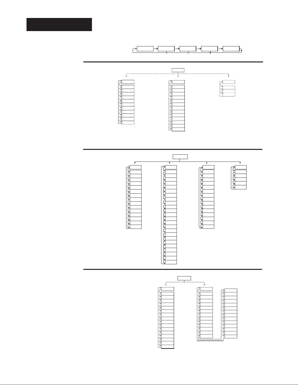
The map on the next page provides an overview of all menus and prompts
and how to navigate between them. There are three main prompts Setup,
Operation and Factory (
[`SEt], [OPEr] and [Fcty]). Beneath these
prompts there are several menus. The Display Loop can be reached from
anywhere using the Display key.
Chapter 1 Starting Out with the
Watlow Series 982
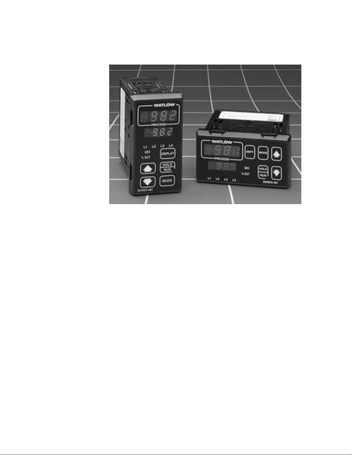
Figure 1.1 Watlow Ramping
Controllers.
Page 6
Factory Fcty ( )
1.2 WATLOW Series 982 User’s Manual
Starting Out with the Watlow Series 982, Chapter 1
Menu Overview
˜
NOTE:
This is a complete
listing of all Series
982 prompts.
Not all prompts will
appear on your
control. They are
dependent on your
configuration and
model number.
Figure 1.2 The Series 982 Map.
7550°F0% OUT LED on
DEV LED on
Process units
Set point 1
Pr2
Process input 2
(SyS)
Alarm 2 low
Alarm 2 high
Alarm 3 low
Alarm 3 high
(System)
Event input 1 statusEi1S
A2LO
A2HI
A3LO
A3HI
A4LO
AUt
A4HI
( )
( )
( )
( )
( )
( )
( )
( )
Auto-tune
Alarm 4 high
Alarm 4 low
( )
( )
( )
Event input 2 status
Ei2S
Event output 3 statusEnt3
Event output 4 statusEnt4
(Pid)
Output 1 integral
Output 1 reset
Output 1 rate
Output 1 derivative
Output 1 cycle time
(PID)
Output 1 proportional band
Pb1
It1
rA1
dE1
Ct1
rE1
Pb2
It2
rA2
rE2
( )
( )
( )
( )
( )
( )
( )
( )
( )
( )
Output 2 integral
Output 2 reset
Output 2 rate
Output 2 proportional band
Ct2
db
dE2
( )
( )
( )
Output 2 cycle time
Output 2 derivative
Dead band
e
Operation Menus
Display Loop
(Lower Display)
Setup Menus
Factory Menus
To navigate:
Press ∂ to return
to the Display Loop
from any location and
to advance through
the Display Loop.
Press
> or < to
move between the
menus.
Press
µ to
advance through a
menu.
Hold
µ while
pressing
> to move
backwards through
the menus.
Press
> or < to
select prompt values.
At the SEt prompt,
press
> and <
another 3 seconds to
enter the Factory
menus.
From the Display
Loop, press
µ to
advance to the
OPEr prompt.
Press
∂ to exit any
menu and reach the
Display Loop at any
time.
Operation OPEr
( )
><
From the Display
Loop, press
> and
< for 3 seconds to
enter the Setup
menus.
><
Setup
><
.
.
.
(See Chapter 7
for all the
Program menus.)
(InPt)
(Input)
In1 ( )
Input 1
dEC1 ( )
Decimal place 1
rL1 ( )
Range low 1
Range high 1
rH1 ( )
Calibration offset 1
CAL1 ( )
rtd1 ( )
Rtd calibration curve 1
Ftr1 ( )
Input 1 software filter
Input 2
In2 ( )
rL2 ( )
Range low 2
rH2 ( )
Range high 2
LmL ( )
Learn low
LmH ( )
Learn high
CAL2 ( )
Calibration offset 2
Hunt ( )
Hunt
SHyS ( )
Slidewire hysteresis
(OtPt)
Ot1 ( )
Prc1 ( )
HyS1 ( )
Ot2 ( )
Prc2 ( )
HyS2 ( )
AL2 ( )
LAt2 ( )
SIL2 ( )
Ot3 ( )
AL3 ( )
HyS3 ( )
LAt3 ( )
SIL3 ( )
Ot4 ( )
AL4 ( )
HyS4 ( )
LAt4 ( )
SIL4 ( )
Aout ( )
Prc3 ( )
ArL ( )
Arh ( )
ACAL ( )
SEt ( )
(Output)
Output 1
Process 1
Hysteresis 1
Output 2
Process 2
Hysteresis 2
Alarm 2
Latching for alarm 2
Silence alarm 2
Output 3
Alarm 3
Hysteresis 3
Latching for alarm 3
Silence alarm 3
Output 4
Alarm 4
Hysteresis 4
Latching for alarm 4
Silence alarm 4
Analog output
Process 3
Retransmit low limit
Retransmit high limit
Retransmit calibration offset
(gLbL)
C_F ( )
Err ( )
Ei1 ( )
Ei2 ( )
AbSP ( )
Anun ( )
LoP ( )
HiP ( )
AtSP ( )
PtyP ( )
gSd ( )
Pout ( )
IdSP ( )
PStr ( )
LOC ( )
(Prog)
( )
FiLE
( )
StEP
( )
StyP
(Global)
Celcius_Fahrenheit
Error Latching
Event input 1
Event input 2
Abort Set Point
Annunciator
Low power limit
High power limit
Auto-tune set point
Program type
Guaranteed soak deviation
Power outage
Idle set point
Profile start
Lockout
bAUd ( )
dAtA ( )
Prot ( )
(Program)
File number
Step number
Step type
(COM)
Addr ( )
intF ( )
( Communication)
Baud rate
Data bit and parity
Protocol type
Address
Interface type
dAtE
SOFt
Sn
AMb
Acnt
gnd
cnt1
cnt2
ity1
ity2
Oty1
Oty2
Oty3
Oty4
dISP
tout
(diAg)
(Diagnostics)
( )
Factory ship date
( )
Software revision
( )
Serial number
( )
Ambient temperatur
( )
Ambient A/D count
( )
Ground A/D count
( )
Input 1 A/D count
( )
Input 2 A/D count
( )
Input 1 module
( )
Input 2 module
( )
Output 1 module
( )
Output 2 module
( )
Output 3 module
( )
Output 4 module
( )
Test displays
( )
Test output
A 50
A 00
tc
A 4H
A 20
A 15
A380
A10u
A 0u
A20A
A 4A
A 0u
A100
(CAL)
(Calibration)
( )
( )
( )
( )
( )
( )
( )
( )
( )
( )
( )
( )
( )
bu15
b380
1 4
1 20
1 0
1 10
2 4
2 20
2 0
2 10
3 LO
3 HI
rSt
dFL
( )
( )
( )
( )
( )
( )
( )
( )
( )
( )
( )
( )
( )
( )
Restore factory values
Default prompts
Page 7
WATLOW Series 982 User’s Manual 1.3
DIP Switches
Starting Out with the Watlow Series 982, Chapter 1
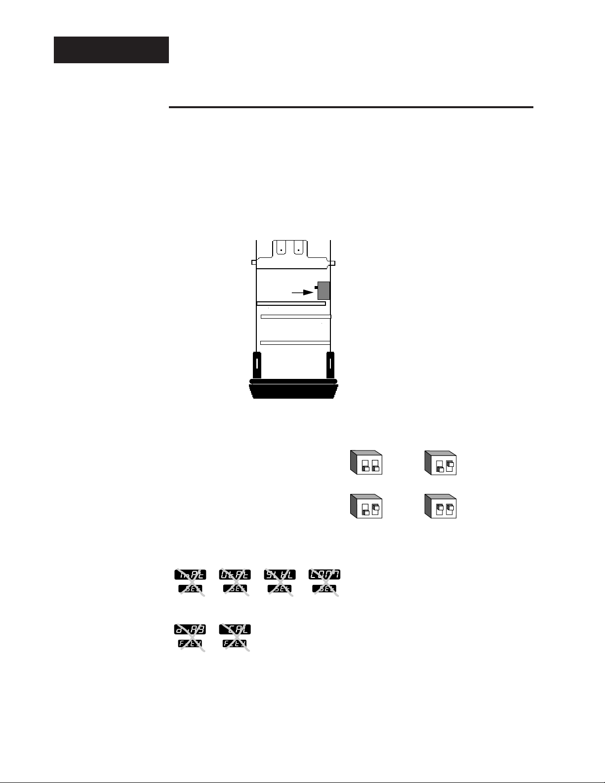
DIP Switch Locations and Functions
The Series 982 has several Dual In-line Package (DIP) Switches inside the
control. Depending on your model number, your unit can have as few as
one DIP switch or as many as five DIP switches. Use the rest of this chapter as a DIP switch reference guide.
To set any DIP switch:
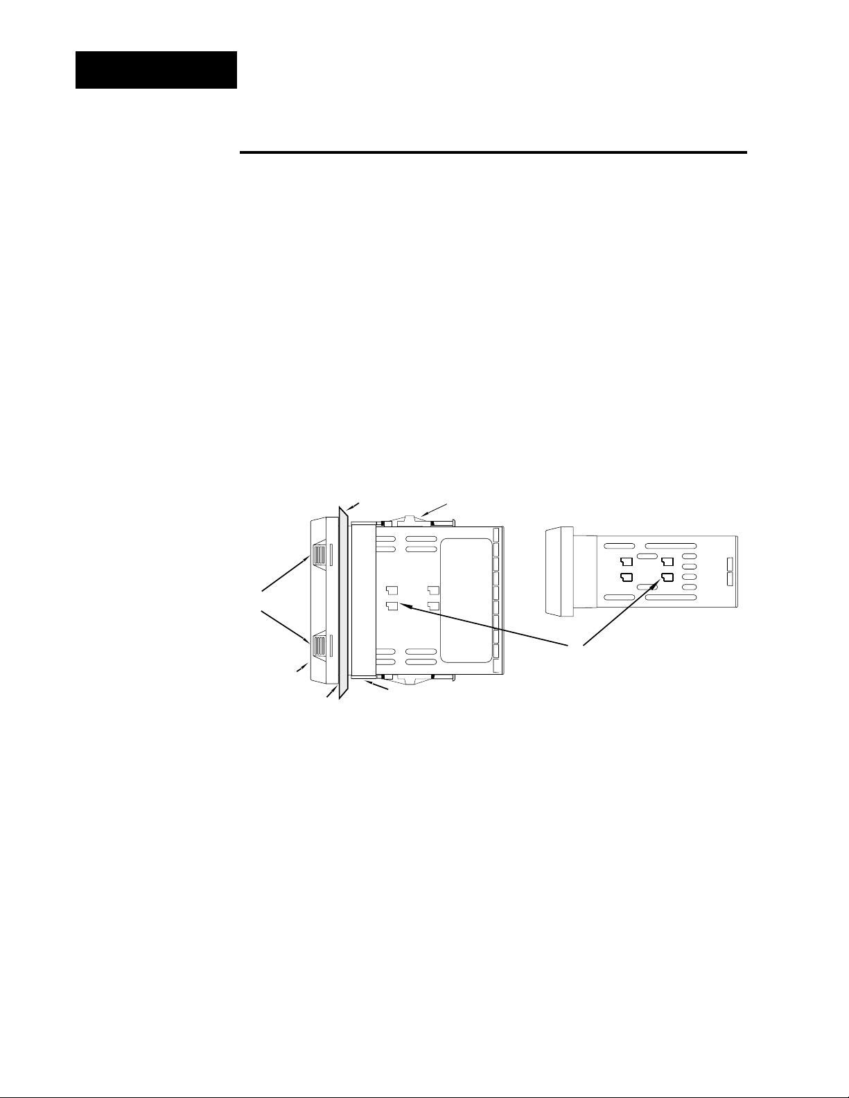
1. Remove the control chassis from the case. Release the two tabs on one
side of the bezel, by pressing in firmly on each until you hear the tab
snap. Release the two tabs on the opposite side of the control. You
may need to rock the bezel back and forth several times to release the
chassis.
2. Use the following graphics in the rest of the chapter to locate and identify
each DIP switch and the desired settings.
TLTL
W
W
A
PROCESS
L1 L2 L3 L4
DEV
% OUT
DISPLAY
SERIES 988
MODE
HOLD
RUN
Release
Tabs
Release
Tabs
Figure 1.3 Press the release
tabs to remove the
controller chassis.
TL
Release
Tabs
W
A
TL
W
MODE
DSPY
PROCESS
HOLD
DEV
% OUT
L1 L2 L3 L4
Release
Tabs
RUN
SERIES 989
Page 8
1.4 WATLOW Series 982 User’s Manual
Starting Out with the Watlow Series 982, Chapter 1
DIP Switches
The Hardware Lockout/Battery Backup DIP Switch
All units are equipped with a DIP switch for hardware lockout of the SEt
and Fcty prompt menus, and to enable battery backup of the Run parameters. The location of the board and switch appear below. The switches are
clearly numbered, and are labeled on the outside of the board. When
Switch #1 is on, battery backup is enabled. When Switch #2 is on, the
menus under the SEt prompt (Input, Output, Global and Communications)
and Fcty prompt (Diagnostics and Calibration) cannot be viewed. When the
control leaves the factory switch #1 is off and switch #2 is off.
Control Chassis
Top View (982 & 984)
Left-side View (981 & 983)
Lockout
DIP
On
Off
Figure 1.4 Battery backup and
hardware lockout
DIP switches.
battery backup of Run prompts or
lockout Setup and Factory menus or
ç
CAUTION:
There is danger of
an explosion if the
battery is incorrectly replaced. This
battery is factory
replaceable only.
Dispose of used
batteries according
to manufacturer’s
recommendations.
12
O
N
Input
Output Global
Communications
↑
12
O
N
↑
Diagnostics Calibration
12
O
N
↑
12
O
N
↑
Page 9
WATLOW Series 982 User’s Manual 1.5
DIP Switches
Starting Out with the Watlow Series 982, Chapter 1
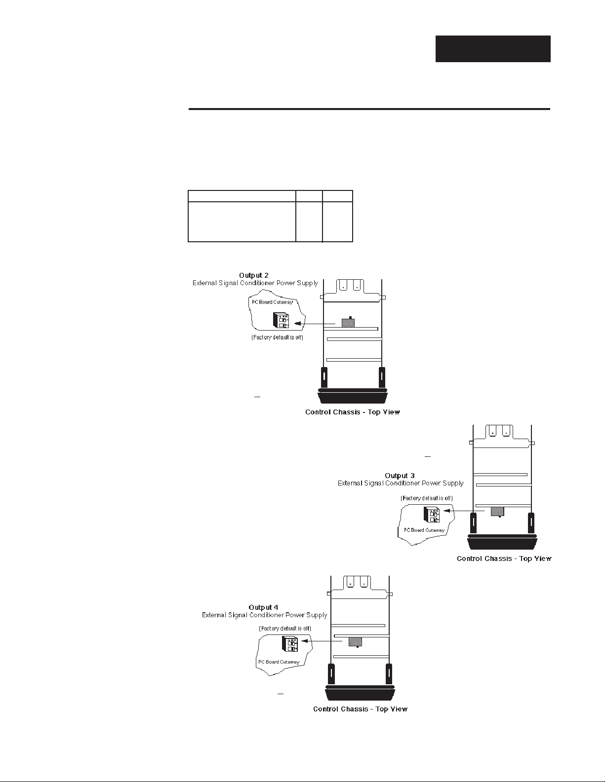
External Power Supply DIP Switches (Option “T”)
Models equipped with an external signal conditioner power supply (Option
“T”), have a DIP switch for selecting the power supply voltage. Output 2, 3
or 4 can be ordered with the external power supply. The location of each
board and DIP switch appear below. When the control leaves the factory,
both switches are off. The figures below show a PC board cutaway for each
DIP switch. See the table to the left
for the power supply switch settings. The settings can be used for
all three output DIP switches. For
other voltage or current ratings contact the factory.
Figure 1.5a Output 2
External Signal
Conditioner
Power Supply.
Figure 1.5b Output 3
External Signal
Conditioner
Power Supply.
Figure 1.5c Output 4
External Signal
Conditioner
Power Supply.
98 _ C - _ _ _ T - _ _ _ _
98 _ C - _ _ _ _ - T _ _ _
98 _ C - _ _ _ _ - _ T _ _
Voltage/Load Current S1 S2
5V ±5% @ 30mA On On
12V ±5% @ 30mA On Off
20V ±5% @ 30mA Off Off
Table 1.5 Power Supply DIP
Switch Settings.
Page 10
1.6 WATLOW Series 982 User’s Manual
Starting Out with the Watlow Series 982, Chapter 1
DIP Switches
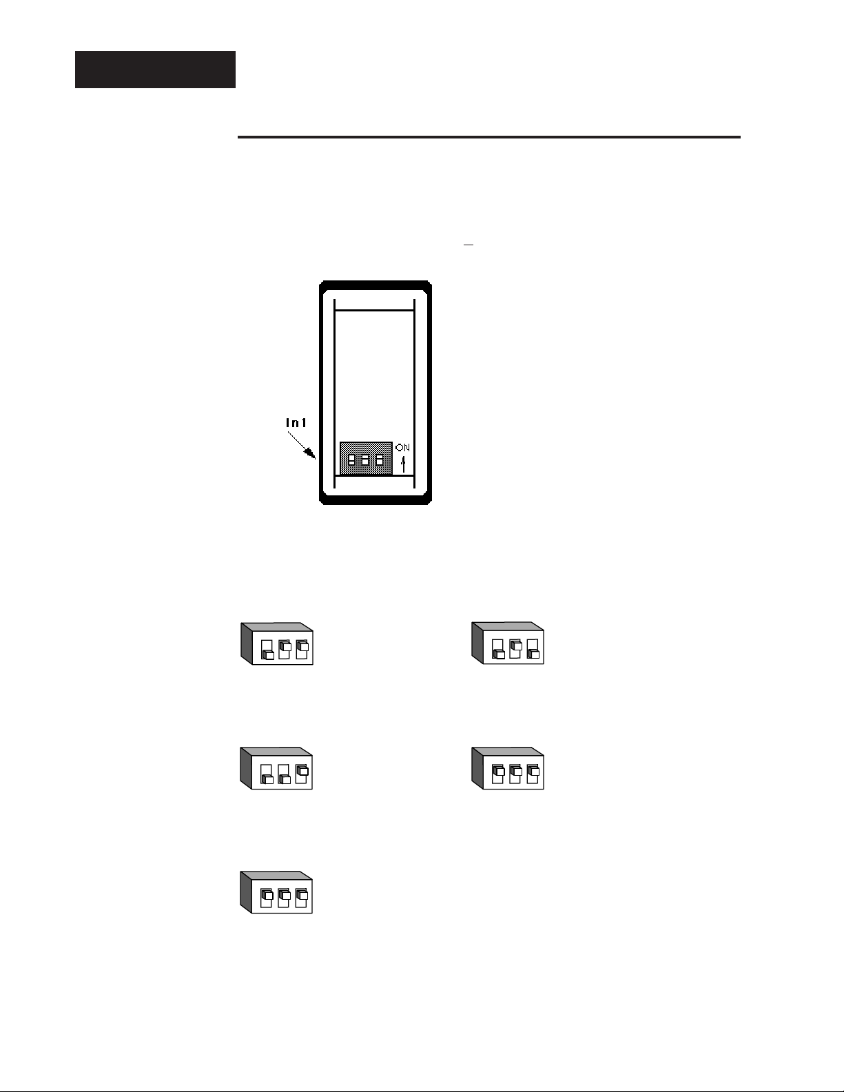
J, K, T, N, C, E, Pt2, D
Thermocouple Input
R, S, B
Thermocouple Input
RTD Input
0-5V, 1-5V or 0-10V Input
0-20mA or 4-20mA Input
Universal Signal Input Type DIP Switches
Remove the chassis from the case. Looking at the back of the control, the
input #1 (In1) switch is located at the base of the unit. Set the DIP switches to match the appropriate sensor input types will automatically match
the DIP switch settings.
If you have model number
98_ C- 1 _ _ _-_ _ _ _
, there is no In1 DIP
switch.
Figure 1.6a Input DIP Switch
Locations.
Figure 6b Input DIP Switch
Settings.
Single Input Unit
98_ C - 2_ _ _ - _ _ _ _
123
O
N
↑
123
O
N
↑
123
O
N
↑
123
O
N
↑
123
O
N
↑
Page 11
WATLOW Series 982 User’s Manual 2.1
Installation and Wiring, Chapter 2
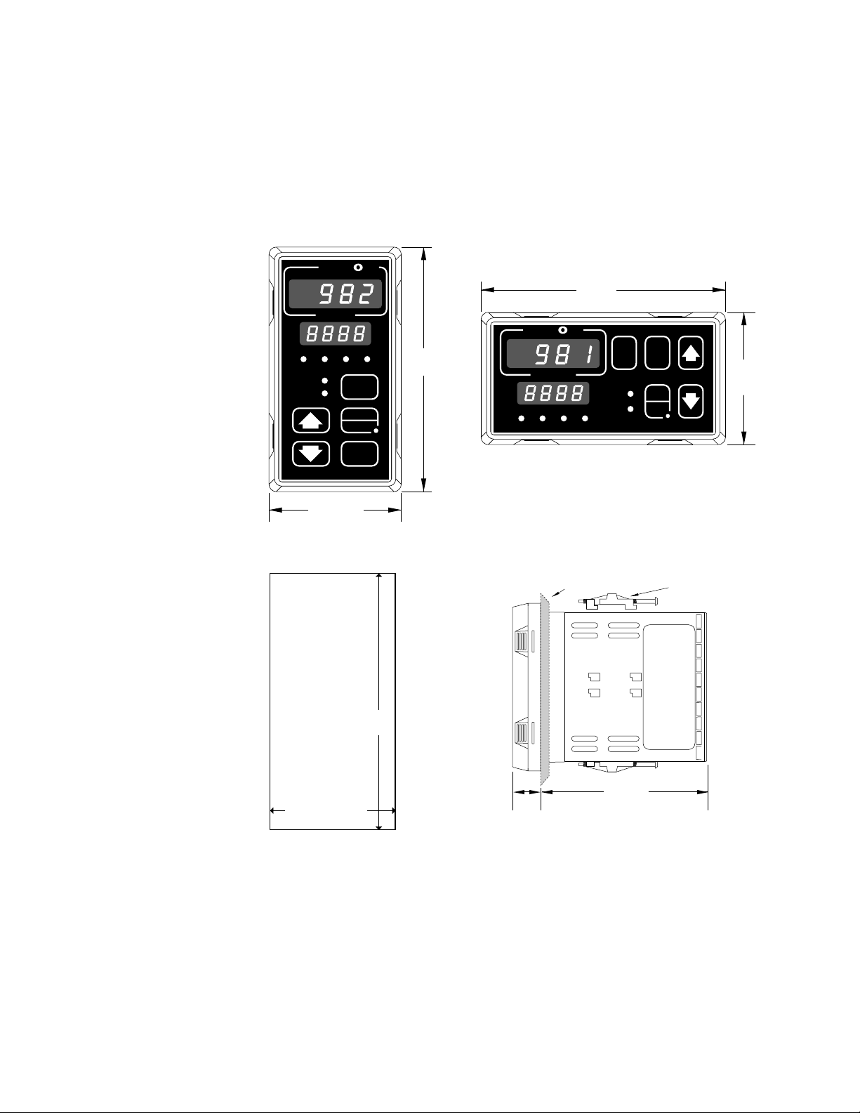
Chapter 2 Installation and Wiring
Figure 2.1 Series 981 and
Series 982
dimensions.
˜
NOTE:
Adjustable mounting brackets can be
side-mounted.
˜
NOTE:
Space panel
cutouts at least 1.66
inches (42.2mm)
apart.
˜
NOTE:
Holes can be cut in
the panel using a
Greenlee 1/8 DIN
Hydraulic Kit
#60068 (punch
#60069, die #60070).
W
A
TL
W
PROCESS
L1 L2 L3 L4
DEV
% OUT
SERIES 988
2.18"
(55 mm)
DISPLAY
HOLD
RUN
MODE
4.03"
(102mm)
(102mm)
W
A
TL
W
PROCESS
L1 L2 L3 L4
4.03"
DSPY
DEV
% OUT
MODE
HOLD
RUN
SERIES 989
2.18"
(55 mm)
Panel Cutout
Maximum Panel
Thickness
0.38" (9.65mm)
3.62" + 0.03 -0.00
(92mm + 0.8)
1.77 + 0.02 -0.00
(45mm + 0.6)
0.68"
(17 mm)
Panel
4.06"
(103 mm)
Mounting Bracket
Adjustable
Page 12
2.2 WATLOW Series 982 User’s Manual
Installation and Wiring, Chapter 2
Installation
Installing the Series 982
Installing and mounting requires access to the back of the panel.
1. Make a panel cutout.
2. To remove the controller chassis from its case, press in firmly on the two
tabs on one side or the top of the bezel until they unsnap, then unsnap
the two tabs on the opposite side or the bottom. Pull the chassis out of
the case by gently rocking it.
3. Slide the case into the panel cutout. Check to see that the gasket is not
twisted, and is seated within the case bezel flush with the panel. Slide
the mounting collar over the back of the control.
Panel
Adjustable
Mounting Bracket
Bezel
External Gasket
Mounting Collar
Release Tabs
Top and Bottom (982 or 984)
or Side (981 or 983) View
Mounting Slots
Side (982 or 984)
or Top and Bottom (981 or 983) View
˜
NOTE:
Removing the controller chassis from
its case makes
mounting easier.
Figure 2.2 Side and top view.
Page 13

WATLOW Series 982 User’s Manual 2.3
Installation and Wiring, Chapter 2
4. Loosen the mounting bracket screws enough to allow for the mounting
collar and panel thickness. Place each mounting bracket into the
mounting slots (head of the screw facing the back of the controller).
Push each bracket backward then down to secure it to the control
case. To guarantee a proper NEMA 4X seal, Series 982 and 984
units (vertical) must have the mounting brackets located on either
side of the unit. When installing Series 981 and 983 units (horizontal) the brackets must be on the top and bottom of the unit.
5. Make sure the case is seated properly. Tighten the installation screws
firmly against the mounting collar to secure the unit. To ensure a
NEMA 4X seal, there should be no space between the bezel and
panel. Overtightening the screws will distort the case and make it diffi-
cult to remove or replace the controller.
6. Insert the controller chassis into its case and press the bezel until all
four tabs snap. Make sure the inside gasket is seated properly and not
twisted.
7. To release the mounting brackets, loosen the mounting bracket screws
and push the brackets forward, then pull it up and out.
ç
CAUTION:
Follow the installation procedure
exactly to guarantee
a proper NEMA 4X
seal. Make sure the
gasket between the
panel and the rim of
the case is not
twisted and is seated properly. Failure
to do so could
result in damage to
equipment.
Installation
Page 14
2.4 WATLOW Series 982 User’s Manual
Installation and Wiring, Chapter 2
Wiring
Wiring the Series 982
Wiring options depend on the model number and DIP switch settings.
Check the terminal designation stickers on either side of the controller
and compare your model number to those shown here and with the model
number breakdown on the inside back cover of this manual.
Input-to-output Isolation
The Series 982 uses optical isolation between the analog inputs and the
controller outputs/digital input. This isolation provides a 500VÅ (VAC)
barrier to prevent ground loops when using grounded sensors and/or
peripheral equipment.
Here is a breakdown of the isolation barriers:
• Analog inputs 1 and 2 are grouped together.
• Outputs 1 through 4 and the standard event input are grouped together.
This does not apply to Output 4 when configured as communications.
• The digital communications output (4) is separate from the above
groups.
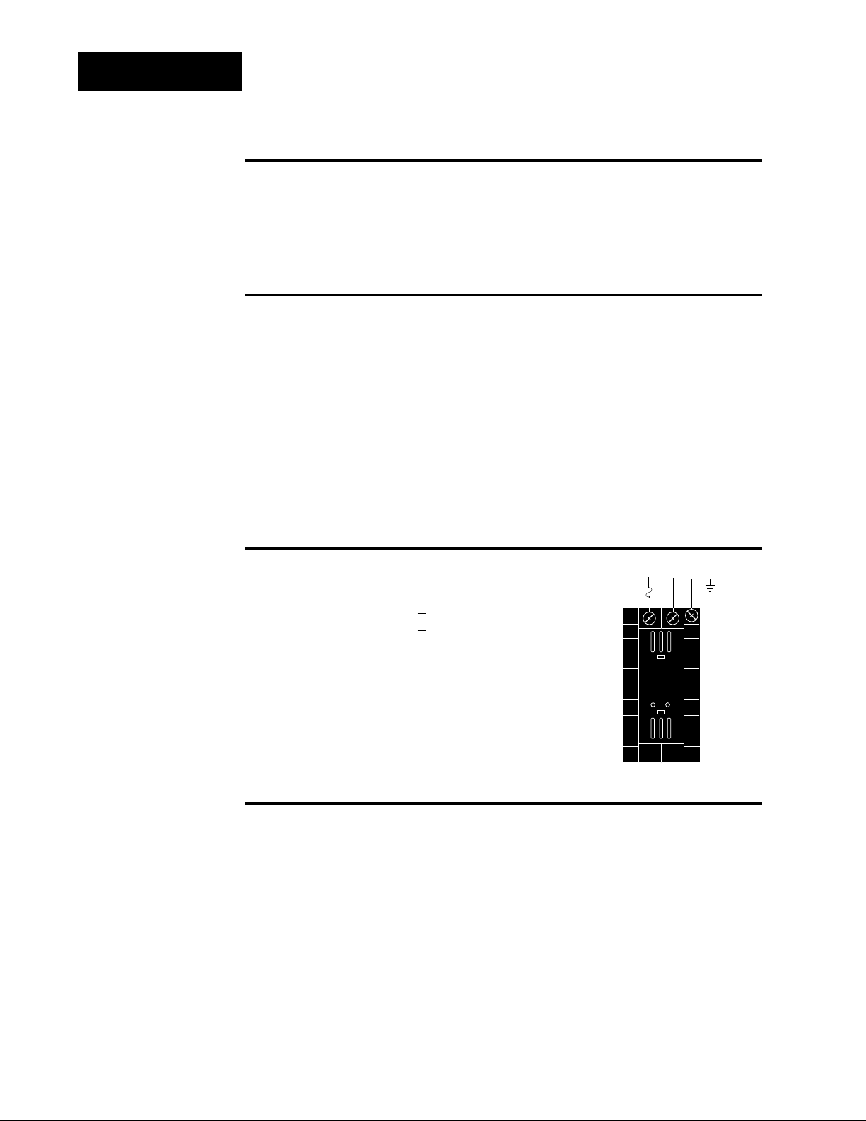
Power Wiring
100 to 240 VÅÅ(ac), nominal (85 to 264 actual)
Horizontal Package 98 1
C - _ _ _ _ - _ _ _ _
Vertical Package 98 2 C - _ _ _ _ - _ _ _ _
24 to 28 V‡‡(ac/dc), nominal (21 to 30 actual)
Horizontal Package 98 3
C - _ _ _ _ - _ _ _ _
Vertical Package 98 4 C - _ _ _ _ - _ _ _ _
Sensor Installation Guidelines
Thermocouple input: Extension wire for thermocouples must be of the
same alloy as the thermocouple itself to limit errors.
100 Ω RTD input: Each 1Ω of lead wire resistance can cause a +2°F
error when using a two-wire RTD. A three-wire RTD sensor overcomes this
problem. All three wires must have the same electrical resistance (i.e.,
same gauge, same length, multi-stranded or solid, same metal).
Maintain isolation between input 1 and input 2 to prevent a ground loop.
A ground loop may cause incorrect readings, dashes across the upper display or the display of error codes.
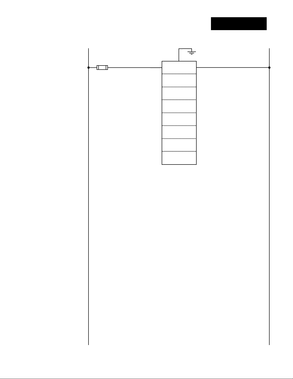
fuse
22
21
earth ground
11
L2L1
+
-
∫
WARNING:
To avoid potential
electric shock, use
National Electric
Code (NEC) safety
practices when
wiring and connecting this unit to a
power source and
to electrical sensors
or peripheral
devices. Failure to
do so could result
in injury or death.
˜
NOTE:
Input-to-output isolation is defeated
when the external
signal conditioner
power supply option
is used to power a
transmitter connected to input 1.
Figure 2.4 Power wiring.
ç
CAUTION:
If high voltage is
applied to the low
voltage unit, irreversible damage
will occur.
Page 15
WATLOW Series 982 User’s Manual 2.5
Installation and Wiring, Chapter 2
Wiring
Wiring 0-20 and 4-20mA Process Inputs
Certain “transmitters” used in process input applications are producing
internal resistor failures in the Watlow Series 988 family of controllers.
This is only apparent with the Series 988 family 1/8 DIN units with
Process Inputs selected (0-20mA or 4-20mA dc only).
We are noticing that an external resistor is required to prevent a high
in-rush current which burns out the Series 988 family controllers’ 7-ohm
internal resistor. This high in-rush current occurs initially on “power-up.”
If the transmitter turns full on for a split second during power-up, the
available current weakens or damages the internal resistor.
Example: 20V / 7 ohms = 2,857mA (too much!).
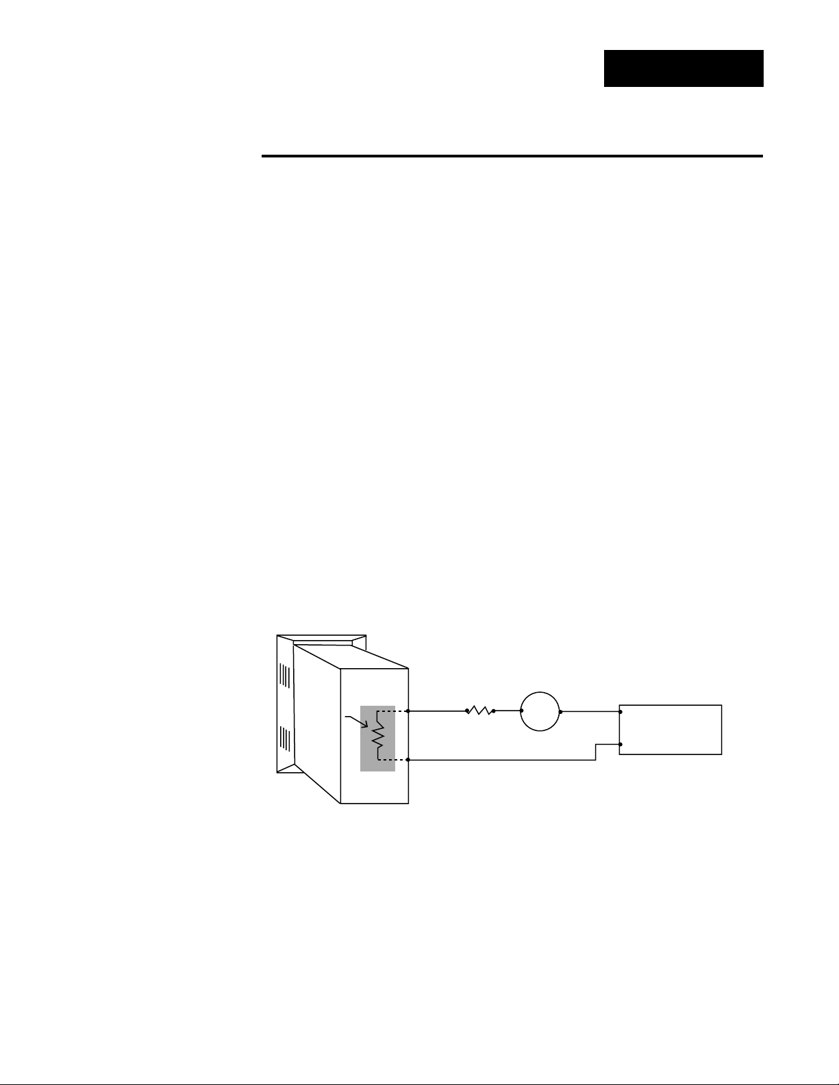
The wiring diagram example below shows an application where a customer
is using a 4-20mA dc transmitter and power supply to feed the input of a
Series 988 controller. The Rx range (100 to 400 ohms) for the external
resistor is recommended. We suggest starting with 250 ohms.
Example: Customer is using a 24VÎ (dc) power supply to power up the
4-20mA dc transmitter that inputs to the Series 988 terminals 8 (-) and 10
(+). To figure out what the internal Series 988’s handling current is for the
0-20mA or 4-20mA dc input to the Series 988 controllers, we need to
apply Ohm’s Law: The square root of Watts divided by Resistance equals
Current. Applying that formula to the example below produces the following: Square Root of (0.125 Watts / 7 ohms) = 134 mA dc (handling input
current). This is the acceptable input current for the Series 988 universal
input board.
Reminder, the input impedance of 7 ohms handles the majority of our
customer applications; the external resistor (Rx) is only for certain transducers/transmitters that spike on power-up or power-down. Please make
sure your customer’s transmitter / transducer fall within our Series 988
family (1/8 DIN) of controllers’ Process Input specification of 7 ohms input
impedance.
Figure 2.5 Process wiring
example.
988 Process
Input Control
4-20mA dc
Internal
Resistor
7Ω
1/8 Watt
+
—
R
100 to 400
ohms
x
Transmitter
—
+
+
24VÎ (dc)
Power Supply
—
Page 16
2.6 WATLOW Series 982 User’s Manual
Installation and Wiring, Chapter 2
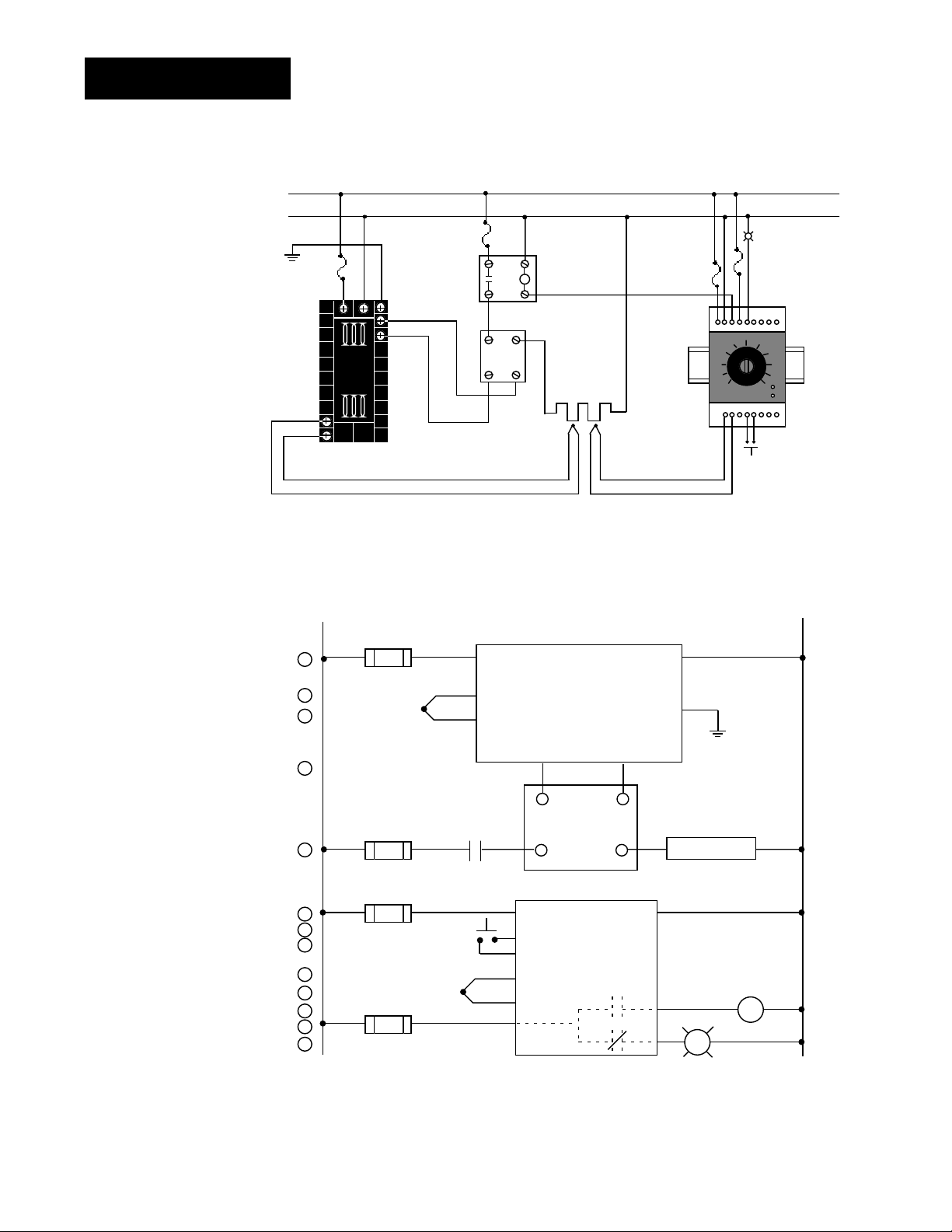
Wiring Example
Figure 2.6 System wiring
example.
∫
WARNING:
To avoid potential
electric shock, use
National Electric
Code (NEC) safety
practices when
wiring and connecting this unit to a
power source and
to electrical sensors or peripheral
devices. Failure to
do so could result
in injury or death.
ç
WARNING:
Install high or low
temperature limit
control protection
in systems where
an over temperature fault condition
could present a fire
hazard or other hazard. Failure to
install temperature
limit control protection where a potential hazard exists
could result in damage to equipment,
property and injury
to personnel.
Ó
WARNING:
To avoid damage to
property and equipment, and/or injury
of loss of life, use
National Electric
Code (NEC) standard wiring practices to install and
operate the Series
982. Failure to do
so could result in
such damage,
and/or injury or
death.
L1
120 VÅ (ac)
L2
eart h ground
(+)
9
10
(-)
red
120VÅ (ac)
1
2
3
4
5
6
7
8
9
10
11
12
13
high limit
mec hanical
fuse
2221
11
12
(+)
(-)
13
982C- 10CA- AARR
rear view
L1
1
1
1 2
1
proc ess sens or li mit sensor
3
4
(+)
5
(-)
1 CR-1
8
11
17
coil
contactor
heater
Series 92
limit control
R
18
15
13 14
10+11
-
norm ally open
mom entary swit ch
1CR
16
SSR-240-10A-DC1
out
12
43
in
21 22
9
10
910
12
13
(+)
14
(-)
15
DC input
SSR
heater
Series 982
982C-10CA-AARR
temperature control
12 13
67
12
13
14
10
11
4
in
3-32VÎ (dc)
(+)
out
24-240VÅ (ac)
92A3-1D J1- 0000
limit control
11
SSR-240-10A-DC1
solid-state relay, DC input
(-)
92A3-1DJ1-0000
3
5
high temperature light
high
tem peratur e
li ght
optional
2
2
2
2
L2
Page 17
WATLOW Series 982 User’s Manual 2.7
Installation and Wiring, Chapter 2
Wiring Notes
ç
WARNING:
To avoid damage to
property and equipment, and/or injury
of loss of life, use
National Electric
Code (NEC) standard wiring practices to install and
operate the Series
982. Failure to do
so could result in
such damage,
and/or injury or
death.
Figure 2.7 Wiring notes.
˜
NOTE:
Sketch in your
application on this
page or a copy of it.
See wiring examples in this chapter.
L1 L2
earth ground
11
21 22
power
Page 18
2.8 WATLOW Series 982 User’s Manual
Installation and Wiring, Chapter 2
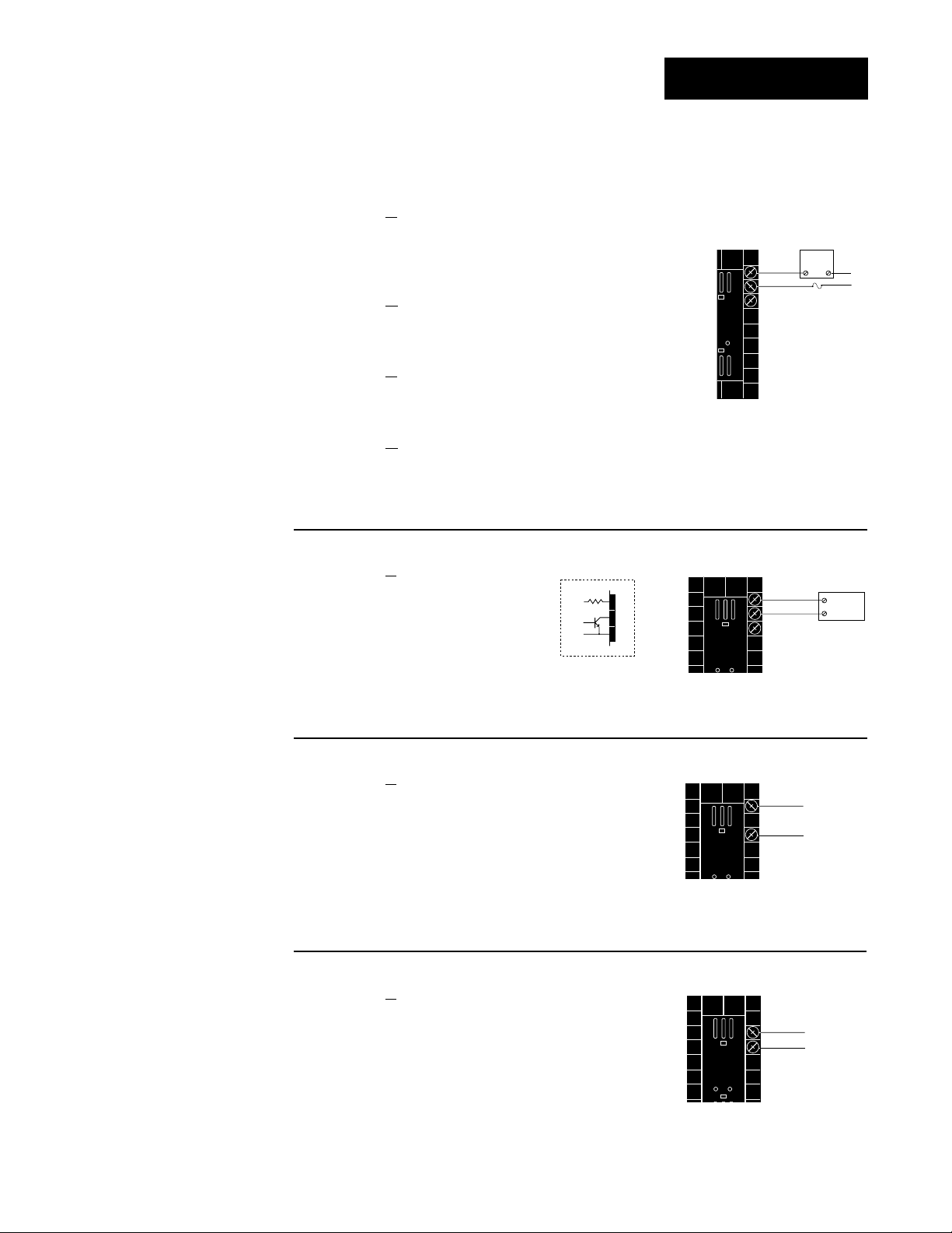
Input 1 Wiring
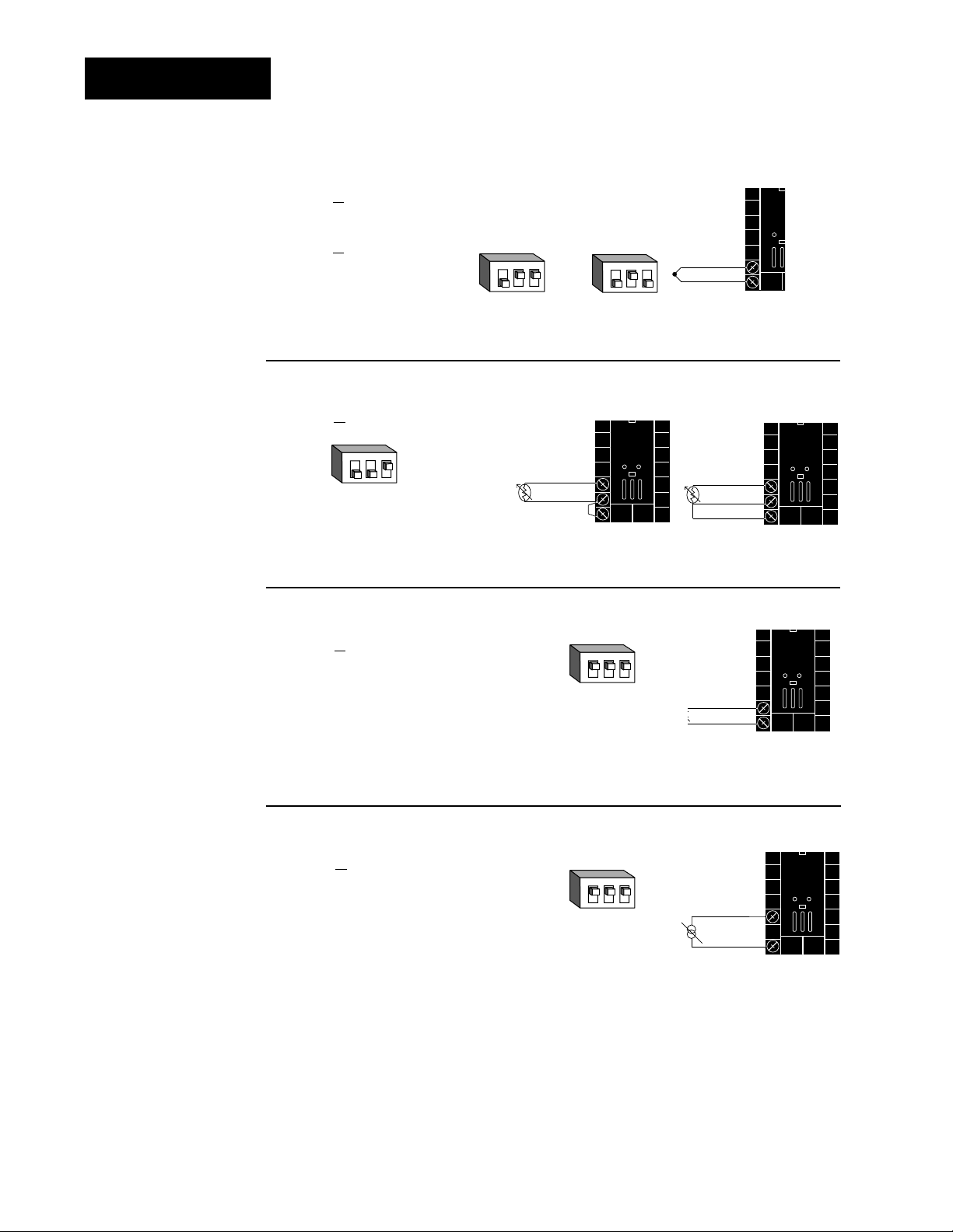
Figure 2.8c —
0-5VÎÎ, 1-5VÎÎor 0-10VÎÎ(dc) Process
Universal signal conditioner
98 _ C - 2 _ _ _ - _ _ _ _
Input impedance: 10KΩ
Figure 2.8a —
Thermocouple
Thermocouple only
98 _ C - 1 _ _ _ - _ _ _ _ (no DIP switches)
Universal signal conditioner
98 _ C - 2 _ _ _ - _ _ _ _
Input impedance: 20MΩ
Figure 2.8b — RTD (2- or 3-wire)
Universal signal conditioner
98 _ C - 2 _ _ _ - _ _ _ _
Figure 2.8d — 0-20mA or 4-20mA Process
Universal signal conditioner
98 _ C - 2 _ _ _ - _ _ _ _
Input impedance: 7Ω
DIP Switch
Setting
R, S, B
DIP Settings
J, K, T, N, C, E, D, Pt2,
DIP Settings
DIP Switch
Setting
DIP Switch
Setting
˜
NOTE:
Successful installation requires five
steps:
• Model number and
software choice
(Appendix);
• DIP switch settings (Chapter 1);
• Sensor match
(Chapter 2 and
Appendix);
• Sensor installation
(Chapter 2); and
• Wiring (Chapter 2).
Jumper
9 to 10
for 2-wire
RTD
ç
CAUTION:
An external resistor
is required for
0-20mA and 4-20mA
process wiring to
prevent a high inrush current which
could burn out the
controller’s 7-ohm
resistor. See page 2.5
for recommendations.
123
O
N
↑
123
O
N
↑
S1
S2
O
N
↑
8
9
10
123
O
N
↑
123
+
9
-
10
8
S1
9
S2
10
S3
9-+
10
123
O
N
↑
-
8
10
+
Page 19
WATLOW Series 982 User’s Manual 2.9
Installation and Wiring, Chapter 2
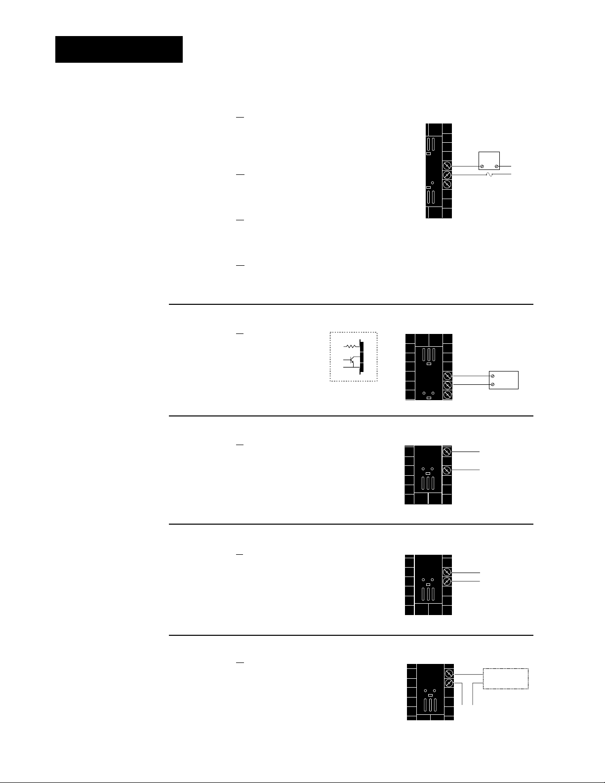
Input 2 Wiring
˜
NOTE:
Successful installation requires five
steps:
• Model number and
software choice
(Appendix);
• DIP switch settings (Chapter 1);
• Sensor match
(Chapter 2 and
Appendix);
• Sensor installation
(Chapter 2); and
• Wiring (Chapter 2).
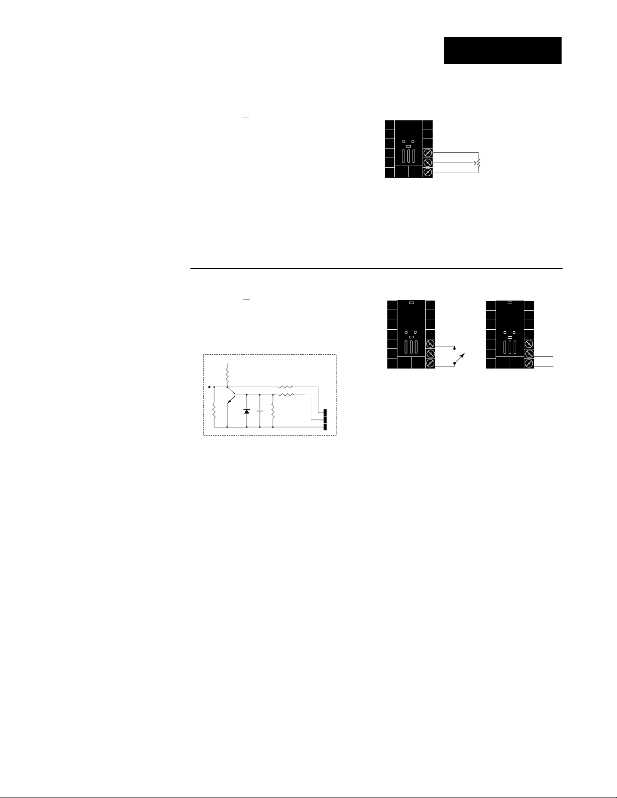
Figure 2.9a — Slidewire Feedback or Potentiometer Input
98 _ C - _ 3 _ _ - _ _ _ _
Slidewire resistance: 100 to 1,200Ω
19
20
18
CW
CCW
Wiper
˜
NOTE:
See Chapter 9 for
information on
slidewire feedback.
Figure 2.9b — Digital Event Input 2
98 _ C - _ 5 _ _ - _ _ _ _
0-3VÎ (dc) Event Input 2 off (open)
14-36VÎ (dc) Event Input 2 on (closed)
18
+5VÎ (dc)
Internal Circuitry
1KΩ
1KΩ
.01µf
750Ω
100Ω
4.7KΩ
20
18
19
20
19
20
+
-
Page 20
2.10 WATLOW Series 982 User’s Manual
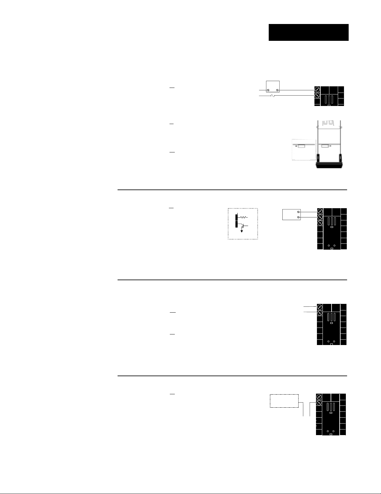
Installation and Wiring, Chapter 2
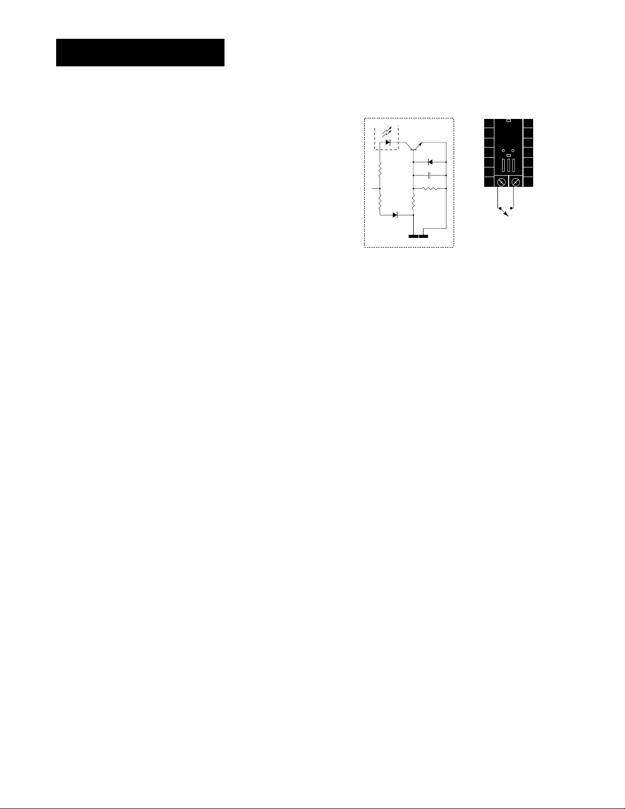
Figure 2.10 —
Digital Event Input 1
Available on all units.
14-36VÎ (dc) Event Input 1 off (open)
0-3VÎ (dc) Event Input 1 on (closed)
˜
NOTE:
Successful installation requires five
steps:
• Model number and
software choice
(Appendix);
• DIP switch settings (Chapter 1);
• Sensor match
(Chapter 2 and
Appendix);
• Sensor installation
(Chapter 2); and
• Wiring (Chapter 2).
Event Input 1 Wiring
4.99KΩ
+24VÎ (dc)
10KΩ
Internal Circuitry
OPTO
ISOLATOR
23
4.99KΩ
24
750Ω
.01µf
23 24
+-
Page 21
WATLOW Series 982 User’s Manual 2.11
Installation and Wiring, Chapter 2
˜
NOTE:
Successful installation requires five
steps:
• Model number and
software choice
(Appendix);
• DIP switch settings (Chapter 1);
• Sensor match
(Chapter 2 and
Appendix);
• Sensor installation
(Chapter 2); and
• Wiring (Chapter 2).
Figure 2.11a —
AC Outputs
Solid-state Relay with Contact Suppression
98 _ C - _ _ B _ - _ _ _ _
0.5 amps, minimum off-state impedance: 20KΩ
Electromechanical Relay with Contact Suppression
(NO and COM contacts only)
98 _ C - _ _ D _ - _ _ _ _
Form C, 5 amps, minimum off-state impedance: 20KΩ
Electromechanical Relay without Contact Suppression
98 _ C - _ _ E _ - _ _ _ _
Form C, 5 amps off-state impedance: 31MΩ
Solid-state Relay without Contact Suppression
98 _ C - _ _ K _ - _ _ _ _
0.5 amps, off-state impedance: 31MΩ
Output 1 Wiring
Figure 2.11b — Switched DC, Open Collector
98 _ C - _ _ C _ - _ _ _ _
Minimum load resistance: 500Ω
Figure 2.11d — 0-5V
ÎÎ
, 1-5VÎÎand 0-10VÎÎ(DC) Process
98 _ C - _ _ F _ - _ _ _ _
Minimum load impedance: 1KΩ
Figure 2.11c — 0-20mA and 4-20mA Process
98 _ C - _ _ F _ - _ _ _ _
Maximum load impedance: 800Ω
14
-
+
12
14
-
+
13
19 to 32VÎ (dc)
+ Vdc
790Ω
Internal Circuitry
12
13
14
External
Load
NO
12
13
COM
14
(#14 for D & E outputs only)
Fuse
NC
12
+
External
-
13
14
COM
L2
L1
Load
Page 22
2.12 WATLOW Series 982 User’s Manual
Installation and Wiring, Chapter 2
Output 2 Wiring
Figure 2.12b — Switched DC, Open Collector
98 _ C - _ _ _ C - _ _ _ _
Minimum load resistance: 500Ω
Figure 2.12d — 0-5V
ÎÎ
, 1-5VÎÎand 0-10VÎÎ(DC) Process
98 _ C - _ _ _ F - _ _ _ _
Minimum load impedance: 1KΩ
Figure 2.12c — 0-20mA and 4-20mA Process
98 _ C - _ _ _ F - _ _ _ _
Maximum load impedance: 800Ω
15
+
-
17
16
+
-
17
Figure 2.12e — External Signal Conditioner Power Supply
98 _ C - _ _ _ T - _ _ _ _
Figure 2.12a —
AC Outputs
Solid-state Relay with Contact Suppression
98 _ C - _ _ _ B - _ _ _ _
0.5 amps, minimum off-state impedance: 20KΩ
Electromechanical Relay with Contact Suppression
(NO and COM contacts only)
98 _ C - _ _ _ D - _ _ _ _
Form C, 5 amps, minimum off-state impedance: 20KΩ
Electromechanical Relay without Contact Suppression
98 _ C - _ _ _ E - _ _ _ _
Form C, 5 amps off-state impedance: 31MΩ
Solid-state Relay without Contact Suppression
98 _ C - _ _ _ K - _ _ _ _
0.5 amps, off-state impedance: 31MΩ
˜
NOTE:
Successful installation requires five
steps:
• Model number and
software choice
(Appendix);
• DIP switch settings (Chapter 1);
• Sensor match
(Chapter 2 and
Appendix);
• Sensor installation
(Chapter 2); and
• Wiring (Chapter 2).
˜
NOTE:
Input-to-output isolation is defeated
when the external
signal conditioner
power supply is
used to power a
transmitter connected to input 1.
˜
NOTE:
See Chapter 1 for
DIP switch location
and settings.
NOTE:
This output cannot
be configured as an
event ouput.
NOTE:
If [SLid] is selected
for [`In2], [`Ot2]
prompt will not
appear.
19 to 32VÎ (dc)
+ Vdc
790Ω
Internal Circuitry
15
16
17
External
Load
15
NO
COM
16
Fuse
NC
17
(#17 for D & E outputs only)
15
+
External
-
16
17
COM
L2
L1
Load
15
+
16
-
-
+
Input
1 or 2
1
2
Transmitter
+V
4-20mA out
-V
Page 23
WATLOW Series 982 User’s Manual 2.13
Installation and Wiring, Chapter 2
Figure 2.13c —
Process Retransmit
0-20mA, 4-20mA, Load impedance: 600Ω max.
98 _ C - _ _ _ _ - M _ _ _
0-5VÎÎ, 1-5VÎÎ, 0-10VÎÎ(dc), Load impedance: 500Ω min.
98 _ C - _ _ _ _ - N _ _ _
˜
NOTE:
Input-to-output isolation is defeated
when the external
signal conditioner
power supply is
used to power a
transmitter connected to input 1.
˜
NOTE:
Successful installation requires five
steps:
• Model number and
software choice
(Appendix);
• DIP switch settings (Chapter 1);
• Sensor match
(Chapter 2 and
Appendix);
• Sensor installation
(Chapter 2); and
• Wiring (Chapter 2).
Figure 2.13d — External Signal Conditioner Power Supply
98 _ C - _ _ _ _ - T _ _ _
Figure 2.13a — AC Outputs
Solid-state Relay with Contact Suppression
98 _ C - _ _ _ _ - B _ _ _
0.5 amps, minimum off-state impedance: 20KΩ
Electromechanical Relay without Contact
Suppression
98 _ C - _ _ _ _ - J _ _ _ _
Form A or B, 5 amps, off-state impedance: 31MΩ
Solid-state Relay without Contact Suppression
98 _ C - _ _ _ _ - K _ _ _ _
0.5 amps, off-state impedance: 31MΩ
Figure 2.13b — Switched DC
98 _ C - _ _ _ _ - C _ _ _
Minimum load resistance: 500Ω
Form B
Form A
Form A or B
alarm jumper
settings (98_C____-J___ only)
Output 3 Wiring
˜
NOTE:
See Chapter 1 for
DIP switch location
and settings.
19 to 32VÎ (dc)
1
790Ω
2
Internal Circuitry
+ Vdc
NC Form B
External
2
1
Fuse
Load
NO Form A
COM
or
External
Load
1
2
1
+
2
-
Transmitter
4-20mA out
+
-
+V
-V
-
+
Input
1 or 2
1
2
1
+
2
-
Page 24
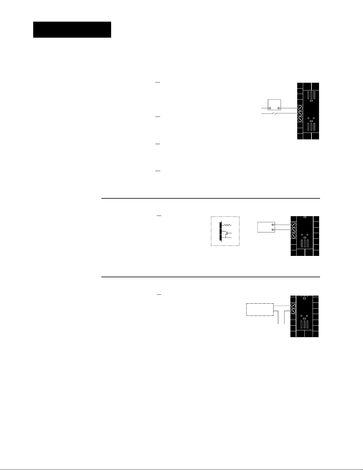
Figure 2.14b — Switched DC, Open Collector
98 _ C - _ _ _ _ - _ C _ _
Minimum load resistance: 500Ω
Figure 2.14a — AC Outputs
Solid-state Relay with Contact Suppression
98 _ C - _ _ _ _ - _ B _ _
0.5 amps, minimum off-state impedance: 20KΩ
Electromechanical Relay with Contact Suppression
(NO and COM contacts only)
98 _ C - _ _ _ _ - _ D _ _ _
Form C, 5 amps, minimum off-state impedance: 20KΩ
Electromechanical Relay without Contact Suppression
98 _ C - _ _ _ _ - _ E _ _ _
Form C, 5 amps, off-state impedance: 31MΩ
Solid-state Relay without Contact Suppression
98 _ C - _ _ _ _ - _ K _ _ _
0.5 amps, off-state impedance: 31MΩ
2.14 WATLOW Series 982 User’s Manual
Installation and Wiring, Chapter 2
Output 4 Wiring
Figure 2.14c —
External Signal Conditioner Power Supply
98 _ C - _ _ _ _ - _ T _ _
5
6
+
-
+V
-V
Transmitter
4-20mA out
Input
1 or 2
+
-
For data communications wiring refer to Data Communications
with the Watlow Series 988 Family of Controllers.
˜
NOTE:
Input-to-output isolation is defeated
when the external
transmitter power
supply is used to
power a signal conditioner connected
to input 1.
˜
NOTE:
See Chapter 1 for
power supply DIP
switch information.
˜
NOTE:
Successful installation requires five
steps:
• Model number and
software choice
(Appendix);
• DIP switch settings (Chapter 1);
• Sensor match
(Chapter 2 and
Appendix);
• Sensor installation
(Chapter 2); and
• Wiring (Chapter 2).
19 to 32VÎ (dc)
+ Vdc
5
790Ω
6
7
Internal Circuitry
External
Load
2
1
Fuse
(#7 for D & E outputs only)
External
Load
COM
+
COM
-
5
NO
6
7
NC
5
6
7
Page 25
WATLOW Series 982 User’s Manual 3.1
Keys & Displays, Chapter 3
After 1 minute with no key activations, the control reverts to the Display Loop. The
process value appears in the upper display and the set point is in the lower display.
For more information on the Display Loop, see the next page.
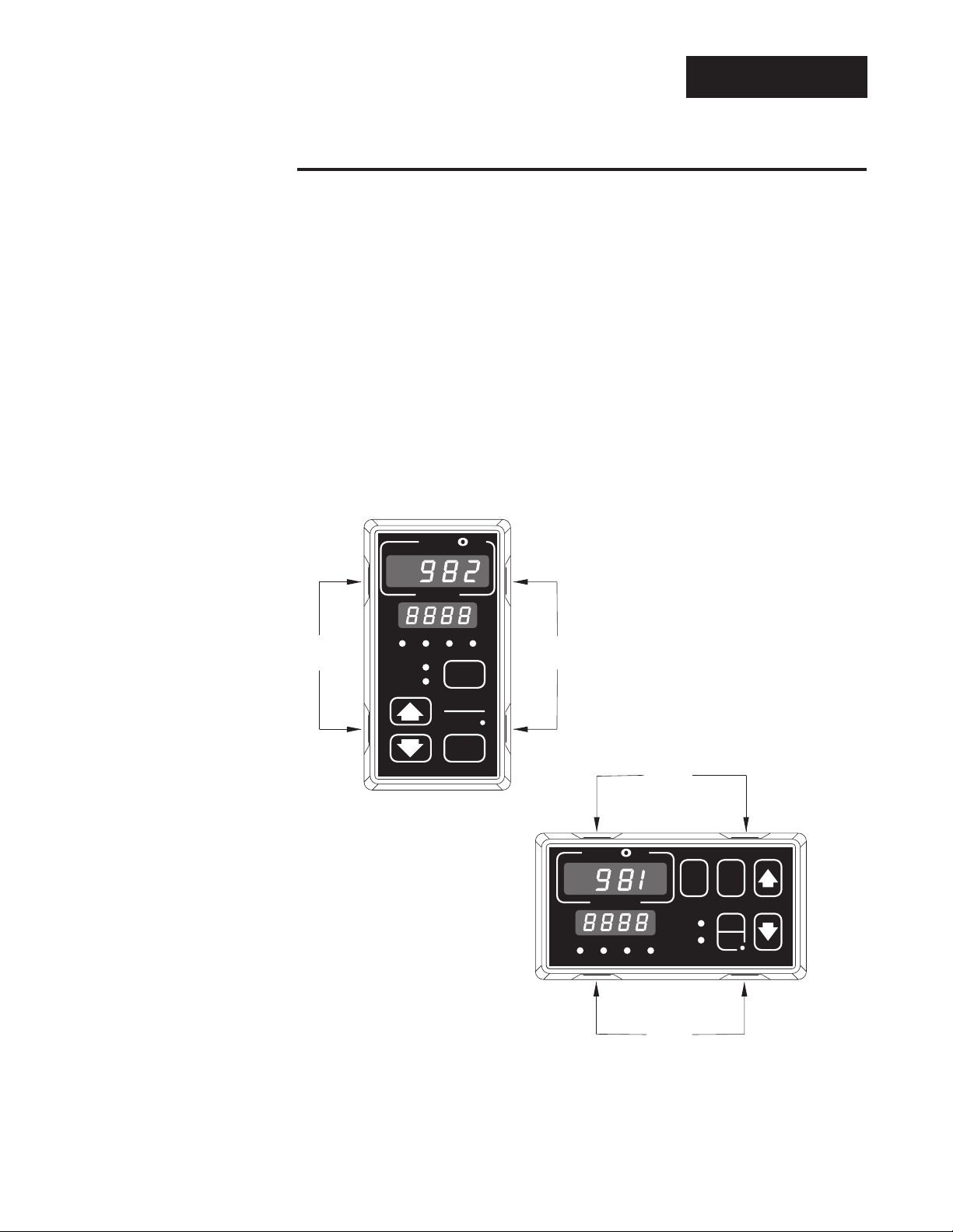
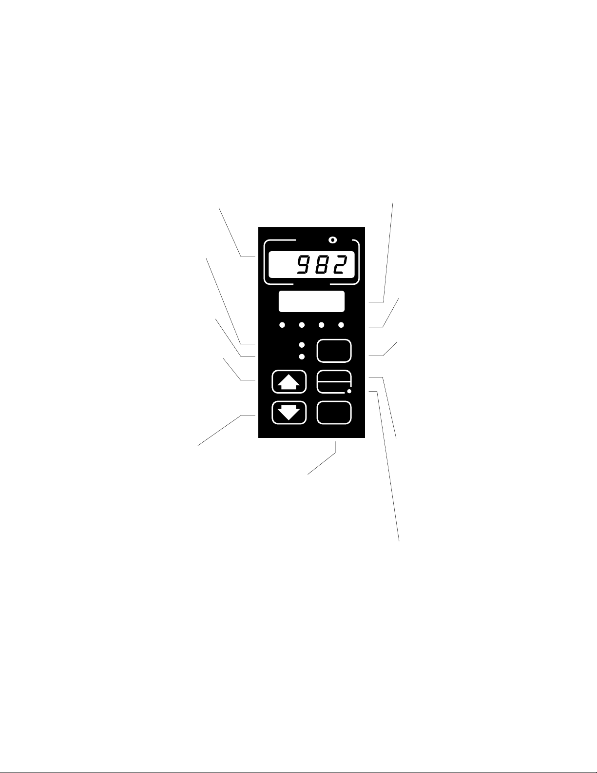
Upper Display
Indicates either actual process value, the operating
prompt values, or error codes. When powering up,
the Process display will be blank for 3 seconds. Red
or green, 0.4” (10mm) high, seven segment, four
digit LED display.
Dev LED
When lit, the deviation from the
current set point is shown in the
lower display.
% Out LED
When lit, the current percent output is shown in the lower display.
Up Key
Increases the value of the displayed prompt. A light touch
increases the value by one.
Holding the key down increases
the value at a rapid rate. New
data is self entering in 5 seconds
or once the Mode key or Display
key is pressed.
Down Key
Decreases the value of the displayed prompt. A light touch
decreases the value by one.
Holding the key down decreases
the displayed value at a rapid
rate. New data is self entering in
5 seconds or once the Mode key
or Display key is pressed.
Up + Down Keys
When pressed simultaneously for
3 seconds, the Setup (SEt)
prompt appears. Continue to
press the Up/Down keys for
another 3 seconds and the
Factory (Fcty) prompt appears.
Lower Display
Indicates the set point, deviation, percent
power temperature unit, menu prompts, or
alarm codes. Red or green, 0.3” (8mm) high,
seven segment, four digit LED display.
L1, L2, L3, L4
When lit, these LEDs indicate
when Output 1, 2, 3, or 4 are
active respectively. Outputs can
be configured as:
Ot1 Control
Ot2 Control or Alarm
Ot3
Alarm, Event or Retransmit
Ot4 Alarm, Event or Com-
munications (flashes on
transmit and receive.)
Display Key
Pressing this key enters the
Display Loop. The Display key
can be pressed at any time to
return to this loop. For more
information on the Display Loop,
see the next page.
Hold/Run Key
Pressed once, it clears a latched
alarm without altering the
Hold/Run status. To run or halt a
program see Chapter 7 for
details.
Hold/Run LED
Lit when the program is running.
When blinking, press the
Hold/Run key again to begin
running. When not lit, the controller is in fixed set point mode
or single.
Mode Key
Steps the control through
the menus. New data is
entered once the Mode
key is pressed.
Mode + Up Key
To move backwards
through the menus, hold
down the Mode key, then
press the Up key to scroll.
The Mode key must be
pressed first and held
before the Up key will
begin scrolling. Scrolling is
disabled once the keys are
released or you reach the
top of the menu.
Figure 3.1 Series 982 Keys
and Displays.
Chapter 3 Front Panel and Display Loop
L1 L2 L3 L4
DEV
% OUT
SERIES 982
A
TL
W
PROCESS
DISPLAY
W
HOLD
RUN
MODE
Page 26

3.2 WATLOW Series 982 User’s Manual
Keys & Displays, Chapter 3
Display Loop
Display Loop
The Display Loop is the “home” state of the Series 982 controller. Pressing
the Display key ∂ returns the controller to the Display Loop from any
prompt in any menu. The controller automatically returns to the Display
Loop from any menu when a minute passes without any keys being
pressed.
Figure 3.2 The Display Loop.
˜
NOTE:
If [``no] is selected
for [`In2], in the
Input Menu, the
[Pr`2] prompt will
not appear.
˜
NOTE:
For information on
Input 1 [`In1] and
Input 2 [`In2]
ranges, refer to
Chapter 4.
Single Set Point
When a program is not running, you can adjust the set point, shown in
the lower display, by pressing the Up-arrow or Down-arrow key or through
serial communications. You can de-engergize all outputs, including event
outputs, by lowering set point 1 to the range low setting minus one, which
will display [`OFF] in the lower display.
Ramping
When a program is running, the set point is controlled by the program.
You can view this set point, but cannot change it while the program is
running. You can select the event output status for each step.
current input 1 reading
set point 1 (change with Up-arrow and Down-arrow keys)
DISPLAY
DISPLAY
DISPLAY
DISPLAY
DISPLAY
DISPLAY
current slidewire percent reading
input 2 process (appears only if controller equipped with slidewire option)
current input 1 reading
deviation from set point, process 1 minus set point 1 (DEV light on)
current input 1 reading
percent output (%OUT light on)
current input 1 reading
units selected (units, °F or °C)
Page 27
WATLOW Series 982 User’s Manual 4.1
Setup Menus, Chapter 4
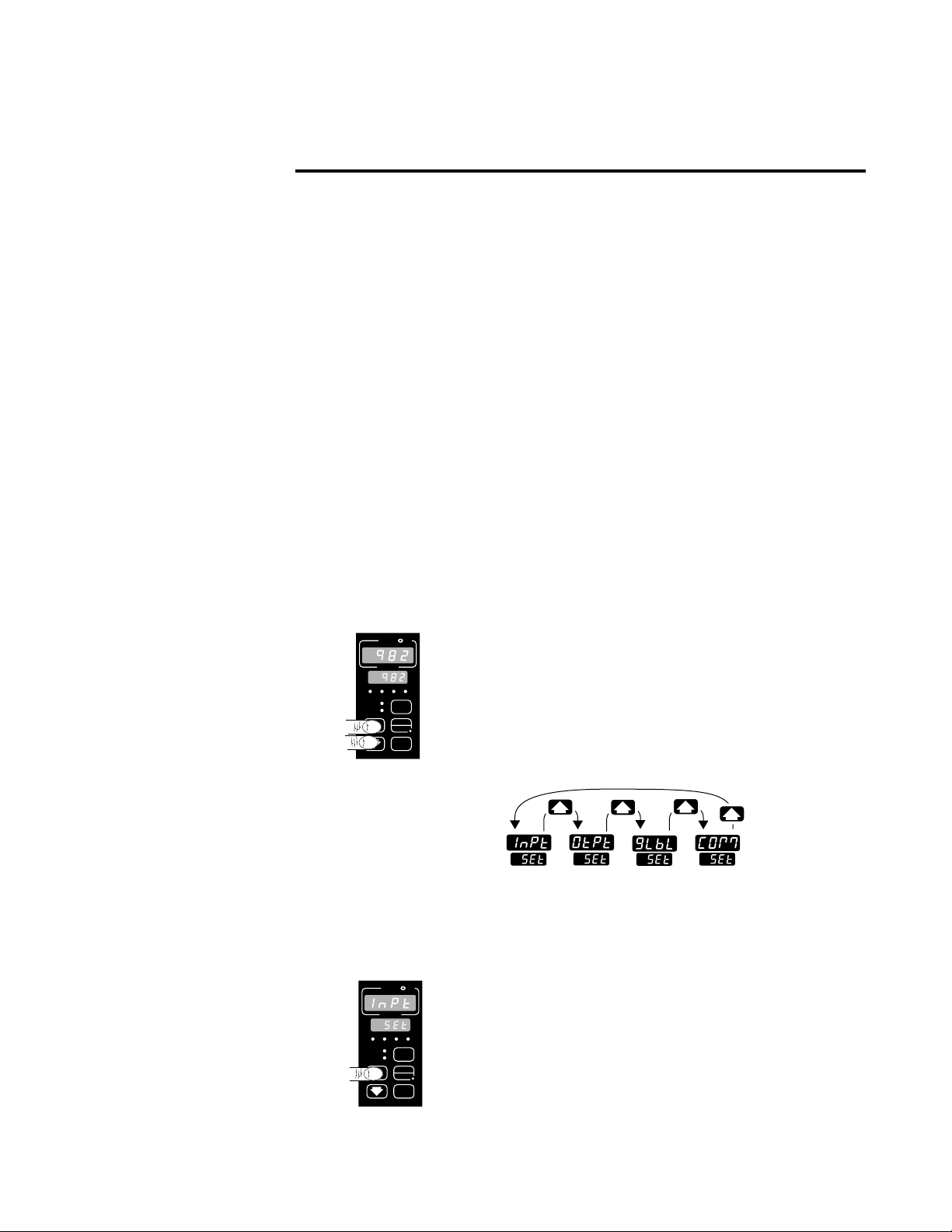
Navigating the Setup Menus
To reach the Setup Menus, begin in the Display Loop and press both the Uparrow > and Down-arrow < keys for three seconds. The Setup Menu
prompt [`SEt] will appear in the lower display, and the Input Menu prompt
[InPt]] will appear in the upper display. The four Setup Menus are: Input
[InPt]; Output [OtPt]; Global [GLbL]; and Communications [COM]. Use the
Up-arrow > or Down-arrow < key to select a menu and the Mode key µ
to step through a menu. The Communications Menu appears only on units
equipped with the data communications option.
You will not see every prompt in any of these menus. The unit’s configuration
and model number determine which prompts appear. After stepping through
each menu, the Series 982 returns to the Setup Menu prompt [`SEt]. Use
the Up-arrow > and Down-arrow < keys to select the next menu, or use
the Mode key µ to advance through the same menu again. To move backwards through the menu hold the Mode key µ down and press the Uparrow key >. Use the Up-arrow > or Down-arrow < key to change the
prompt setting.
Refer to the Appendix for model number options. For information about
communications and the communications prompts, refer to the supplemental manual Data Communications with the Watlow Series 988 Family of
Controllers.
Chapter 4 The Setup Menus
Figure 4.1 Navigating the
Setup Menus.
❶ Begin in the Display Loop, and press the Up-arrow
> and Down-arrow < keys simultaneously to
reach the Setup Menus.
❷ Press the Up-arrow key > to select one of the
Setup Menus.
˜
NOTE:
The lockout DIP
switch hides the
Setup Menus. See
Chapter 1.
ç
CAUTION:
When navigating
thru Setup Menus,
outputs will be disabled.
˜
NOTE:
Press the Display
key ∂ to return to
the Display Loop
from any point in
any menu.
PROCESS
L1 L2 L3 L4
DEV
% OUT
SERIES 982
L1 L2 L3 L4
DEV
% OUT
SERIES 982
W
A
W
PROCESS
TL
DISPLAY
HOLD
RUN
MODE
TL
A
DISPLAY
HOLD
MODE
W
Input
Menu
p. 4.2
W
Output
Menu
p. 4.12
Global
Menu
p. 4.28
Communications
Menu
p. 4.38
RUN
Page 28
4.2 WATLOW Series 982 User’s Manual
Setup Menus, Chapter 4
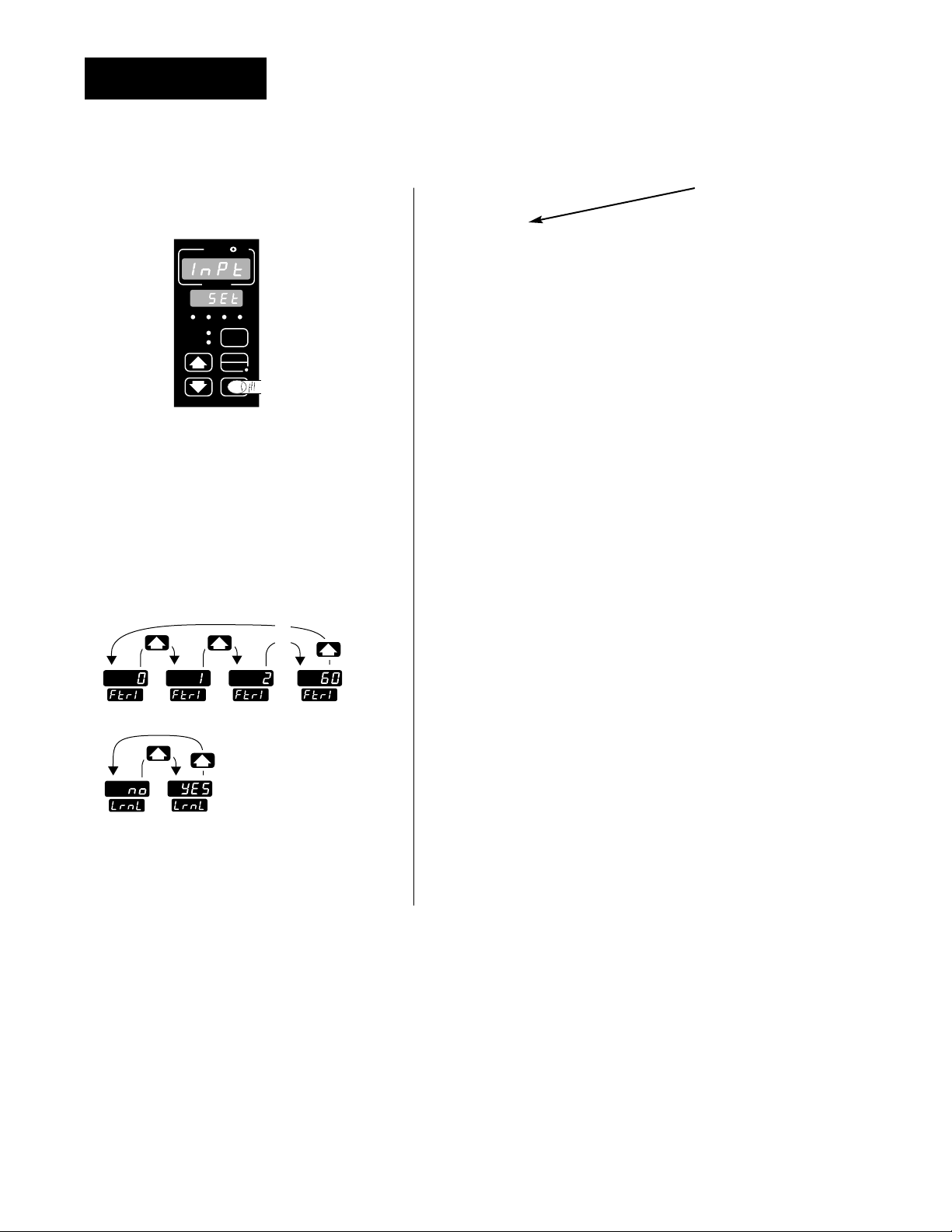
Figure 4.2 The Input Menu.
Setup-Input
❸ Select the Input Menu, then
press the Mode key µ to step
through the prompts.
❹ Press the Up-arrow key > or
the Down-arrow key < to select
one of the prompt values.
*Prompts may not appear, depending
on controller configuration.
Reaching the Input Menu
→ [InPt] Input Menu
↑ µ
[`SEt] Setup Menus
↓
?
µ
[`In1] Input 1 (page 4.3)
↓ ?
µ
[dEC1] *Decimal 1
↓ ?
µ
[`rL1] Range Low 1
↓ ?
µ
[`rH1] Range High 1
↓ ?
µ
[CAL1] Calibration Offset 1
↓ ?
µ
[rtd1] *RTD Calibration Curve 1
↓ ?
µ
[Ftr1] Input 1 Software Filter
↓
?
µ
[`In2] *Input 2 (page 4.8)
↓ ?
µ
[`rL2] *Range Low 2
↓ ?
µ
[`rH2] *Range High 2
↓ ?
µ
[LrnL] *Learn Low
↓ ?
µ
[LrnH] *Learn High
↓ ?
µ
[CAL2] *Calibration Offset 2
↓ ?
µ
[Hunt] *Hunt (page 4.11)
↑
↓
?
←µ [SHYS] *Slidewire Hysteresis
Enter your settings,
from the controller’s
upper display.
W
TL
W
A
PROCESS
L1 L2 L3 L4
DEV
DISPLAY
% OUT
HOLD
RUN
MODE
SERIES 982
…
…
…
Page 29

Input Prompts
When you are in the Setup menus, the Series 982 displays the menu selection ( [InPt], [OtPt], [GLbL] or [COM] ) in the upper display, and [`SEt] in
the lower display.
The Up-arrow > or Down-arrow key < selects another menu. Press the
Mode key µ to display the prompt in the lower display and its value in the
upper display. Use the Up-arrow > or Down-arrow < key to change the
value in the upper display. The new value will not take effect until after a
five-second delay or until you press the Mode key µ.
Input 1
Select sensor type for input 1. This selection must match the sensor type
connected to terminals 8, 9 and 10. See Appendix for more information
about sensors.
• Changing the value of [`In1] changes all other prompts to the factory
default values, except the Communications and Lockout menus, the
[`C_F] prompt in the Global Menu and the [`dFL] prompt in the
Calibration Menu. If you change the value, the default warning [dFLt]
will flash in the upper display.
• Changes do not take effect automatically after five seconds; you must
press the Mode key µ to enter the sensor type change and advance to
the next prompt.
[`In1] This prompt always appears.
If Default
↓ ↓
98__-1___-____
no DIP J K T N E W5 W3 Pt2
[```J] [```H] [```t] [```n] [```E] [```C] [```d] [`Pt2]
thermocouple [`In1] [`In1] [`In1] [`In1] [`In1] [`In1] [`In1] [`In1]
only
98__-2___-____
Input 1 DIP J K T N E W5 W3 Pt2
[```J] [```H] [```t] [```n] [```E] [```C] [```d] [`Pt2]
[`In1] [`In1] [`In1] [`In1] [`In1] [`In1] [`In1] [`In1]
thermocouple
Input 1 DIP
RSB
[```r] [```S] [```b]
[`In1] [`In1] [`In1]
thermocouple
O
N
↑
123
O
N
↑
123
WATLOW Series 982 User’s Manual 4.3
Setup Menus, Chapter 4
Setup-Input
˜
NOTE:
Decimal points may
not always be in the
position specified
below depending on
the the settings in
the Decimal 1
[dEC1] parameter in
the Input Menu.
ç
CAUTION:
Changing the value
of [`In1] changes
most other prompts
to the factory
default values and
clears all program
steps. Verify the
correct sensor type
before making a
change. Document
all settings before
changing sensor
type. Failure to follow this guideline
could result in damage to equipment or
property.
[`In1]
Input 1 continued
on next page.
[`In1]
Page 30

4.4 WATLOW Series 982 User’s Manual
Setup Menus, Chapter 4
[`In1]
Input 1 continued
from previous
page.
Setup-Input
If Default
↓↓
Input 1 DIP RTD RTD(0.1°)
[`rtd] [`r†d]
[`In1] [`In1]
RTD
Input 1 DIP 4-20mA 0-20mA 0-5VÎ 1-5VÎ 0-10VÎ (dc)
[4-20] [0-20] [`0-5] [`1-5] [0-10]
[`In1] [`In1] [`In1] [`In1] [`In1]
process
Decimal 1
Select the decimal point location for process type input 1 data. This
prompt, in conjunction with the Range Low and Range High prompts,
allows you to format and limit units of measure for process 1.
• All prompts with units of measure related to input 1 will display in the
selected decimal format.
• This affects propbands, alarm set points, process set points, calibration
offsets, deadbands and ranges.
[dEC1] This prompt appears only if you have set input 1 [`In1] to a
process input.
Default
↓
[```)] [``)0] [`)00] [)000]
[dEC1] [DEC1] [dEC1] [dEC1]
O
N
↑
123
O
N
↑
123
[dEC1]
Page 31

WATLOW Series 982 User’s Manual 4.5
Setup Menus, Chapter 4
Setup-Input
˜
NOTE:
These values do not
affect the low or the
high set point limit
for process alarms.
Range Low 1 and Range High 1
Select the low and high limits for input 1. These prompts limit the
adjustment range for the set points. The default values are the same as
the limits of the sensor you selected by setting the input 1 DIP switch and
selecting a value for Input 1 [`In1].
• Process inputs are scaled by these values. Range high is the value displayed when the maximum process signal is present at the input. Range
low is the value displayed when the minimum process signal is present
at the input.
Example: Set [`In1] to [4-20]mA.
Set [`rL1] to [`100].
Set [`rH1] to [`500].
A 4mA input will display [`100].
A 12mA input will display [`300].
A 20mA input will display [`500].
• The low and high values of each sensor type are listed on the specifications page of the Appendix.
• Choose between Fahrenheit and Celsius at the [`C_F] prompt in the
Global Menu.
[`rL1] [`rH1] These prompts always appear.
Default Default Default Default
↓↓ ↓↓
[``°F] [``°C]
[`rL1] [`rH1] [`rL1] [`rH1]
[```J] [``32]…[1500] [```0]…[`816] 98__-1__-___ or
[`in1] [`rL1] [`rH1] [`rL1] [`rH1] 98__-2__-___
(K)
[```H] [-328]…[2500] [-200]…[1371]
[```t] [-328]…[`750] [-200]…[`399]
[```n] [``32]…[2372] [```0]…[1300]
[```E] [-328]…[1470] [-200]…[`799]
(W5)
[```C] [``32]…[4200] [```0]…[2316]
(W3)
[```d] [``32]…[4200] [```0]…[2316]
[`Pt2] [``32]…[2543 [```0]…[1395]
[`rL1]
[`rH1]
Range Low 1 and
Range High 1
continued on next
page.
[`rL1]
[`rH1]
Page 32

4.6 WATLOW Series 982 User’s Manual
Setup Menus, Chapter 4
Setup-Input
˜
NOTE:
These values do not
affect the low or the
high set point limit
for process alarms.
[`rL1]
[`rH1]
Range Low 1 and
Range High 1
continued from
previous page.
[``°F] [``°C]
[`rL1] [`rH1] [`rL1] [`rH1]
[```r] {``32]…[3200] [```0]…[1760] 98__-2__-___ only
[`in1]
[```S] [``32]…[3200] [```0]…[1760]
[```b] [``32]…[3300] [```0]…[1816]
[`rtd] [-328]…[1472] [-200]…[`800]
[`r†d] [-9(9]…[99(9] [-7#3]…[53&7]
[4-20] [-999]…[`999] units
[0-20] [-999]…[`999] units
[`0-5] [-999]…[`999] units
[`1-5] [-999]…[`999] units
[0-10] [-999]…[`999] units
Calibration Offset 1
Offset the input 1 signal by a positive or negative value. This allows you
to compensate for lead resistance, sensor errors or other factors.
[CAL1] This prompt always appears.
If Default
↓↓
[``°F [-999] … [```0] … [`999]
[`C_F] [CAL1] [CAL1] [CAL1]
(Global Menu)
[``°F]&[`r†d] [-9(9] … [[``)0] … [`9(9]
[`C_F] [`In1] [CAL1] [CAL1] [CAL1]
(Global Menu) (Input Menu)
[``°C] [-555] … [[```0] … [`555]
[`C_F] [CAL1] [CAL1] [CAL1]
(Global Menu)
[``°C]&[`r†d] [-5%5] … [[``)0] … [`5%5]
[`C_F] [`In1] [CAL1] [CAL1] [CAL1]
(Global Menu) (Input Menu)
[-999] … [```0] … [`999]
units
a process input
[CAL1] [CAL1] [CAL1]
is selected
[CAL1]
Page 33

RTD Calibration Curve 1
Select the calibration curve for the RTD 1 input. The RTD input uses
either the European (DIN, 0.003850Ω/Ω/°C) or the Japanese (JIS,
0.003916Ω/Ω/°C) linearization standard.
[rtd1] This prompt appears only if you have set [`In1] to [`rtd] or
[`r†d].
Default
↓
[`din] … [`JIS]
[rtd1] [rtd1]
Software Filter 1
Select the filter time constant, in seconds, for input 1. This smooths a
rapidly changing input signal for display or control purposes.
• Select a positive value to filter only the display.
• Select a negative value to filter the input signal.
• Set the value to [```0] to disable the filter.
[Ftr1] This prompt always appears.
Default
↓
[`-60] … [```0] … [``60]
[Ftr1] [Ftr1] [Ftr1]
WATLOW Series 982 User’s Manual 4.7
Setup Menus, Chapter 4
Setup-Input
[rtd1]
[Ftr1]
Page 34

4.8 WATLOW Series 982 User’s Manual
Setup Menus, Chapter 4
Setup-Input
NOTE:
If [``no] is selected
for [`In2] none of
the other input 2
prompts will
appear.
Input 2
Select sensor type for input 2. This selection must match the sensor
type connected to terminals 18, 19 and 20. See Appendix for more information about sensors.
• Changing the value of [`In2] changes all other prompts to the factory default values, except the Communications and Lockout menus,
the [`C_F] prompt in the Global Menu and the [`dFL] prompt in the
Calibration Menu. If you change the value, the default warning
[dFLt] will flash in the upper display.
• Changes do not take effect automatically after five seconds; you must
press the Mode key µ to enter the sensor type change and advance to
the next prompt.
[`In2] This prompt and other Input 2 prompts appear only on controllers
equipped with input 2 hardware (not 98__-_0__-____).
If Default
↓ ↓
98__-3___-____
no DIP slidewire
[``no] [SLid]
resistance [`In2] [`In2]
only
98__-5___-____
no DIP event 2
[``no] [`Ei2]
digital event [``In2] [`In2]
only
Range Low 2
Select the low resistance of the slidewire potentiometer.
[`rL2] This prompt appears only on controllers with [`In2] (Input Menu)
set to [SLiD].
Default
↓
[```0] … [`rH2]
[`rL2] [`rL2]
[`In2]
ç
CAUTION:
Changing the value
of [`In2] changes
most other prompts
to the factory
default values and
clears all program
steps. Verify the
correct sensor type
before making a
change. Document
all settings before
changing input
type. Failure to follow this guideline
could result in damage to equipment or
property.
NOTE:
See Chapter 9 for
more information
on slidewire feedback.
[`rL2]
NOTE:
These values do not
affect the low or the
high set point limit
for process alarms.
NOTE:
If [SLid] is selected
for [`In2], [`Ot2]
prompt will not
appear.
Page 35

WATLOW Series 982 User’s Manual 4.9
Setup Menus, Chapter 4
Setup-Input
Range High 2
Select the high resistance of the slidewire potentiometer.
[`rH2] This prompt appears only on controllers with [`In2] (Input Menu)
set to [SLiD].
Default
↓
[`rL2] … [```0] … [1200]
[`rH2] [`rH2] [`rH2]
Learn Low
Write the low-end resistance of the slidewire potentiometer to the
range low 2 parameter.
[LrnL] This prompt appears only on controllers with [`In2] (Input Menu)
set to [SLiD].
Default
↓
[``no] [`YES]
[LrnL] [LrnL]
Learn High
Write the high-end resistance of the slidewire potentiometer to the
range low 2 parameter.
[LrnH] This prompt appears only on controllers with [`In2] (Input Menu)
set to [SLiD].
Default
↓
[``no] [`YES]
[LrnH] [LrnH]
[`rH2]
NOTE:
See Chapter 9 for
more information
on slidewire feedback.
[LrnL]
[LrnH]
NOTE:
These values do not
affect the low or the
high set point limit
for process alarms.
Page 36

4.10 WATLOW Series 982 User’s Manual
Setup Menus, Chapter 4
Setup-Input
Calibration Offset 2
Offset the input 2 signal by a positive or negative value. This allows
you to compensate for lead resistance, sensor errors or other factors.
[CAL2] This prompt appears only on controllers with [`In2] (Input Menu)
set to [SLiD].
If Default
↓↓
[``°F [-999] … [```0] … [`999]
[`C_F] [CAL2] [CAL2] [CAL2]
(Global Menu)
[``°F]
&
[`r†d] [-9(9] … [[``)0] … [`9(9]
[`C_F] [`In1] [CAL2] [CAL2] [CAL2]
(Global Menu) (Input Menu)
[``°C] [-555] … [[```0] … [`555]
[`C_F] [CAL2] [CAL2] [CAL2]
(Global Menu)
[``°C]
&
[`r†d] [-5%5] … [[``)0] … [`5%5]
[`C_F] [`In1] [CAL2] [CAL2] [CAL2]
(Global Menu) (Input Menu)
[-999] … [```0] … [`999]
units
a process input
[CAL2] [CAL2] [CAL2]
is selected
Hunt
Set the deadband, as a percentage of output, to keep the valve from
hunting.
• The slidewire hysteresis [SHYS] setting provides additional control over a
valve.
[Hunt] This prompt appears only on controllers with [`In2] (Input Menu)
set to [SLiD].
Default
↓
[``)1] … [``!0] … [10)0]
[Hunt] [Hunt] [Hunt]
[CAL2]
˜
NOTE:
See Chapter 9 for
more information
on slidewire feedback.
[Hunt]
Page 37

Slidewire Hysteresis
Set the inner hysteresis, the point at which the valve output turns
off.
• The figure below illustrates the interaction between slidewire hysteresis
[SHYS] and hunt [Hunt].
[SHYS] This prompt appears only on controllers with [`In2] (Input Menu)
set to [SLiD].
Default
↓
[```0] [Hunt]
[SHYS] [SHYS]
WATLOW Series 982 User’s Manual 4.11
Setup Menus, Chapter 4
Setup-Input
[SHYS]
Figure 4.11 Hunt and slidewire
inner hysteresis.
Hunt
Slidewire
Hysteresis
turn-off point (open)
turn-off point (close)
turn-on point (open)
turn-on point (close)
slidewire position
set point
Page 38

4.12 WATLOW Series 982 User’s Manual
Setup Menus, Chapter 4
Setup-Output
❸ Press the Mode key µ to
step through the prompts.
❹ Press the Up-arrow key > or
the Down-arrow key < to
select one of the prompt values.
❶ Begin in the Display Loop,
and press the Up-arrow > and
Down-arrow < keys simultaneously for three seconds to
reach the Setup Menus.
❷ Press the Up-arrow key > to
select one of the Setup Menus.
Reaching the Output
Menu
Figure 4.12 Navigating the
Output Menu.
*Prompts may not
appear, depending
on controller configuration.
→
[OtPt] Output Menu
↑
µ
[`SEt] Setup Menus
↓
?
µ
[`Ot1] Output 1 (page 4.13)
↓ ?
µ
[Prc1] *Process 1
↓ ?
µ
[HYS1] Hysteresis 1
↓
?
µ
[`Ot2] *Output 2 (page 4.15)
↓ ?
µ
[Prc2] *Process 2
↓ ?
µ
[HYS2] *Hysteresis 2
↓ ?
µ
[`AL2] *Alarm 2
↓ ?
µ
[LAt2] *Latching 2
↓ ?
µ
[SIL2] *Silencing 2
↓
?
µ
[`Ot3] *Output 3 (page 4.19)
↓ ?
µ
[`AL3] *Alarm 3
↓ ?
µ
[HYS3] *Hysteresis 3
↓ ?
µ
[LAt3] *Latching 3
↓ ?
µ
[SIL3] *Silencing 3
→
→
?
µ
[`Ot4] *Output 4 (page 4.22)
↓ ?
µ
[`AL4] *Alarm 4
↓ ?
µ
[HYS4] *Hysteresis 4
↓ ?
µ
[LAt4] *Latching 4
↓ ?
µ
[SIL4] *Silencing 4
↓
?
µ
[Aout] *Analog Output (page 4.25)
↓ ?
µ
[Prc3] *Process 3
↓ ?
µ
[`ArL] *Retransmit Low Limit
↓ ?
µ
[ArH] *Retransmit High Limit
↑
↓ ?
←µ [ACAL] *Retransmit Calibration Offset
Enter your settings,
from the controller’s
upper display.
Input
Menu
p. 4.2
Output
Menu
p. 4.12
Global
Menu
p. 4.28
Communications
Menu
p. 4.38
…
…
…
Page 39

WATLOW Series 982 User’s Manual 4.13
Setup Menus, Chapter 4
Setup-Output
Output Prompts
When you are in the Setup menus, the Series 982 displays the menu
selection ( [InPt], [OtPt], [GLbL] or [COM] ) in the upper display, and
[`SEt] in the lower display.
The Up-arrow > or Down-arrow key < selects another menu. Press the
Mode key µ to display the first prompt in the lower display and its value
in the upper display. Use the Up-arrow > and Down-arrow < keys to
change the value in the upper display. The new value will not take effect
until after a five-second delay or until you press the Mode key µ.
Output 1
Set the way that output 1 will respond to a difference between the set
point and an input variable.
• [``Ht] select reverse action, so that output 1 responds when the input
signal is less than the set point.
• [``CL] select direct action, so that output 1 responds when the input
signal is more than the set point.
[`Ot1] This prompt always appears.
Default
↓
[``Ht] [``CL]
[`Ot1] [`Ot1]
˜
NOTE:
Decimal points may
not always be in the
position specified
below depending
on the the settings
in the Decimal 1
[deC1] parameters
in the Input Menu.
[`Ot1]
Page 40

4.14 WATLOW Series 982 User’s Manual
Setup Menus, Chapter 4
Setup-Output
Process 1
Select the process range for output 1.
[Prc1] This prompt appears only on controllers equipped with output 1
process hardware (98__-__F_-____).
Default
↓
4-20mA 0-20mA 0-5VÎ 1-5VÎ 0-10VÎ (dc)
[4-20] [0-20] [`0-5] [`1-5] [0-10]
[Prc1] [Prc1] [Prc1] [Prc1] [Prc1]
Hysteresis 1
Select the switching hysteresis for output 1. This determines the
change in temperature or process units needed to turn the output from
full on to full off.
[HYS1] This prompt does not appear on controllers equipped with output 1
process hardware (98__-__F_-____).
If Default
↓↓
[``°F [```1] … [```3] … [`999]
[`C_F] [HYS1] [HYS1] [HYS1]
(Global Menu)
[``°F]
&
[`r†d] [``)1] … [[``#0] … [`9(9]
[`C_F] [`In1] [HYS1] [HYS1] [HYS1]
(Global Menu) (Input Menu)
[``°C] [```1] … [[```2] … [`555]
[`C_F] [HYS1] [HYS1] [HYS1]
(Global Menu)
[``°C]
&
[`r†d] [``)1] … [[``@0] … [`5%5]
[`C_F] [`In1] [HYS1] [HYS1] [HYS1]
(Global Menu) (Input Menu)
[```1] … [```3] … [`999]
units
a process input
[HYS1] [HYS1] [HYS1]
is selected
[HYS1]
[Prc1]
Page 41

WATLOW Series 982 User’s Manual 4.15
Setup Menus, Chapter 4
Setup-Output
Output 2
Set the way that output 2 will respond to a difference between the set
point and an input variable.
• [`AL2] de-energizes output 2 in an alarm condition.
• [AL2n] energizes output 2 in an alarm condition.
• [``Ht] select reverse action, so that output 2 responds when the input
signal is less than the set point. This prompt only appears if [`Ot1] is set
to [``CL].
• [``CL] select direct action, so that output 2 responds when the input
signal is more than the set point. This prompt only appears if [`Ot1] is
set to [``Ht].
[`Ot2] This prompt appears only on controllers equipped with output 2
hardware (not 98__-___A-____). [`AL2] and [AL2n] do not appear if output 2
is a process output (98__-___F-____). [``Ht] and [``CL] do not appear if
[AL90] (in the Global Menu) is set to [dUPL].
Default
↓
[``no] [`AL2] [Al2n] [``Ht] or [``CL]
[`Ot2] [`Ot2] [`Ot2] [`Ot2] [`Ot2]
Process 2
Select the process range for output 2.
[Prc2] This prompt appears only on controllers equipped with output 2
process hardware (98__-___F-____) and with [`Ot2] not set to [``no].
Default
↓
4-20mA 0-20mA 0-5VÎ 1-5VÎ 0-10VÎ (dc)
[4-20] [0-20] [`0-5] [`1-5] [0-10]
[Prc2] [Prc2] [Prc2] [Prc2] [Prc2]
[`Ot2]
[Prc2]
NOTE:
[`Ot2] prompt will
not appear if
[SLid] is selected
for [`In2].
Page 42

4.16 WATLOW Series 982 User’s Manual
Setup Menus, Chapter 4
Setup-Output
Hysteresis 2
Select the switching hysteresis for output 2. This determines the
change in temperature or process units needed to turn the output from
full off to full on.
• If [`AL2] is set to [rAtE] settings for [HYS2] will be in degrees per
minute or units per minute.
• If the input referenced by [`AL2] is set to [`r†d] the range is affected as
listed below.
[HYS2] This prompt appears only on controllers equipped with output 2
hardware and with [`Ot2] not set to [``no]. This prompt does not appear
on controllers with [`In2] set to [SLid] or on controllers equipped with
output 2 process hardware.
If Default
↓↓
[``°F [```1] … [```3] … [`999]
[`C_F] [HYS2] [HYS2] [HYS2]
(Global Menu)
[``°F]
&
[`r†d] [``)1] … [[``#0] … [`9(9]
[`C_F] [`In1] [HYS2] [HYS2] [HYS2]
(Global Menu) (Input Menu)
[``°C] [```1] … [[```2] … [`555]
[`C_F] [HYS2] [HYS2] [HYS2]
(Global Menu)
[``°C]
&
[`r†d] [``)1] … [[``@0] … [`5%5]
[`C_F] [`In1] [HYS2] [HYS2] [HYS2]
(Global Menu) (Input Menu)
[```1] … [```3] … [`999]
units
a process input
[HYS2] [HYS2] [HYS2]
is selected
[HYS2]
Page 43

WATLOW Series 982 User’s Manual 4.17
Setup Menus, Chapter 4
Setup-Output
Alarm 2
Select the alarm type for alarm 2. Select the trigger points for the alarm
with the [A2LO] and [A2HI] settings in the System Menu [`SYS].
• [`Pr1] uses the process signal from input 1. Changing the set point
does not change the alarm response.
• [`dE1] uses a deviation from the input 1 signal. Changing the set point
changes the alarm response.
• [rAtE] uses the rate of change at input 1 in degrees per minute.
[`AL2] This prompt appears only on controllers equipped with output 2
hardware (not 98__-___A-____), and with [`Ot2] set to [`AL2] or [AL2n].
Default
↓
[`Pr1] [`de1] [rAtE]
[`AL2] [`AL2] [`AL2]
Latching 2
Select whether alarm 2 will be latching or non-latching. A latching
alarm [`LAt] must be turned off manually. A non-latching alarm [`nLA]
turns off when an alarm condition no longer exists.
[LAt2] This prompt appears only on controllers equipped with output 2
hardware (not 98__-___A-____) and with [`Ot2] set to [`AL2] or [AL2n].
Default
↓
[`nLA] [`LAt]
[LAt2] [LAt2]
˜
NOTE:
See Chapter 8 for
more information
on alarms.
[`AL2]
[LAt2]
Page 44

[`Ot3]
4.18 WATLOW Series 982 User’s Manual
Setup Menus, Chapter 4
Setup-Output
Silencing 2
Select silencing to inhibit alarm 2 on startup and to allow the operator to reset the alarm output, not the visual display.
• Silencing disables the alarm until the signal is between [A2LO] and
[A2HI].
[`AL2] This prompt appears only on controllers equipped with output 2
hardware (not 98__-___A-____) and with [`Ot2] set to [`AL2] or [AL2n].
Default
↓
[`OFF] [``On]
[SIL2] [SIL2]
Output 3
Set the way that output 3 will respond to a difference between the
set point and an input variable.
• [`AL3] de-energizes output 3 in an alarm condition.
• [AL3n] energizes output 3 in an alarm condition.
• [Ent3] sets output 3 to an event output.
[`Ot3] This prompt appears only on controllers equipped with output 3
hardware for a relay (98__-____-B___, 98__-____-J___ or 98__-____-K___) or
switched dc (98__-____-C___).
Default
↓
[`AL3] [AL3n] [Ent3] [``no]
[`Ot3] [`Ot3] [`Ot3] [`Ot3]
˜
NOTE:
See Chapter 8 for
more information
on alarms.
˜
NOTE:
See Chapter 8 for
more information
on alarms.
[SIL2]
Page 45

WATLOW Series 982 User’s Manual 4.19
Setup Menus, Chapter 4
Setup-Output
Alarm 3
Select the alarm type for alarm 3.
• [`Pr1] uses the process signal from input 1.
• [`dE1] uses a deviation from the input 1 signal.
• [rAtE] uses the rate of change at input 1 in degrees per minute.
[`AL3] This prompt appears only on controllers equipped with output 3
hardware for a relay (98__-____-B___, 98__-____-J___ or 98__-____-K___) or
switched dc (98__-____-C___), and with [`Ot3] set to [`AL3] or [AL3n].
Default
↓
[`Pr1] [`de1] [rAtE]
[`AL3] [`AL3] [`AL3]
[`AL3]
Page 46

4.20 WATLOW Series 982 User’s Manual
Setup Menus, Chapter 4
Setup-Output
Hysteresis 3
Select the switching hysteresis for alarm 3. This determines the change
in temperature or process units needed to turn the output from full off to
full on.
• If [`AL3] is set to [rAtE] settings for [HYS3] will be in degrees per
minute or units per minute.
• If the input referenced by [`AL3] is set to [`r†d] the range is affected as
listed below.
[HYS3] This prompt appears only on controllers equipped with output 3
hardware for a relay (98__-____-B___, 98__-____-J___ or 98__-____-K___) or
switched dc (98__-____-C___) and with [`Ot3] set to [`AL3] or [AL3n].
If Default
↓↓
[``°F [```1] … [```3] … [`999]
[`C_F] [HYS3] [HYS3] [HYS3]
(Global Menu)
[``°F]
&
[`r†d] [``)1] … [[``#0] … [`9(9]
[`C_F] [`In1] [HYS3] [HYS3] [HYS3]
(Global Menu) (Input Menu)
[``°C] [```1] … [[```2] … [`555]
[`C_F] [HYS3] [HYS3] [HYS3]
(Global Menu)
[``°C]
&
[`r†d] [``)1] … [[``@0] … [`5%5]
[`C_F] [`In1] [HYS3] [HYS3] [HYS3]
(Global Menu) (Input Menu)
[```1] … [```3] … [`999]
units
a process input
[HYS3] [HYS3] [HYS3]
is selected
˜
NOTE:
See Chapter 8 for
more information
on alarms.
[HYS3]
Page 47

WATLOW Series 982 User’s Manual 4.21
Setup Menus, Chapter 4
Setup-Output
Latching 3
Select whether alarm 3 will be latching or non-latching. A latching
alarm [`LAt] must be turned off manually. A non-latching alarm [`nLA]
turns off when an alarm condition no longer exists.
[LAt3] This prompt appears only on controllers equipped with output 3
hardware for a relay (98__-____-B___, 98__-____-J___ or 98__-____-K___) or
switched dc (98__-____-C___) and with [`Ot3] set to [`AL3] or [AL3n].
Default
↓
[`nLA] [`LAt]
[LAt3] [LAt3]
Silencing 3
Select silencing to inhibit alarm 3 on startup and to allow the operator to reset the alarm output, not the visual display.
• Silencing disables the alarm until the signal is between [A3LO] and
[A3HI].
[SIL3] This prompt appears only on controllers equipped with output 3
hardware for a relay (98__-____-B___, 98__-____-J___ or 98__-____-K___) or
switched dc (98__-____-C___) and with [`Ot3] set to [`AL3] or [AL3n].
Default
↓
[`OFF] [``On]
[SIL3] [SIL3]
˜
NOTE:
See Chapter 8 for
more information
on alarms.
[LAt3]
[SIL3]
Page 48

4.22 WATLOW Series 982 User’s Manual
Setup Menus, Chapter 4
Setup-Output
Output 4
Set the way that output 4 will respond to a difference between the set
point and an input variable.
• [`AL4] de-energizes output 4 in an alarm condition.
• [AL4n] energizes output 4 in an alarm condition.
• [Ent4] sets output 4 to an event output.
[`Ot4] This prompt appears only on controllers equipped with output 4
hardware for a relay (98__-____-_B__, 98__-____-_D__ , 98__-____-_E__ or
98__-____-_K__) or switched dc (98__-____-_C__).
Default
↓
[`AL4] [AL4n] [Ent4] [``no]
[`Ot4] [`Ot4] [`Ot4] [`Ot4]
Alarm 4
Select the alarm type for alarm 4.
• [`Pr1] uses a process signal from input 1.
• [`dE1] uses a deviation from the input 1 signal.
• [rAtE] uses the rate of change at input 1 in degrees per minute.
[`AL4] This prompt appears only on controllers equipped with output 4
hardware for a relay (98__-____-_B__, 98__-____-_D__ , 98__-____-_E__ or
98__-____-_K__) or switched DC (98__-____-_C__) and [`Ot4] is set to
[`AL4] or [AL4n].
Default
↓
[`Pr1] [`dE1] [rAtE]
[`AL4] [`AL4] [`AL4]
[`AL4]
˜
NOTE:
See Chapter 8 for
more information
on alarms.
[`Ot4]
Page 49

WATLOW Series 982 User’s Manual 4.23
Setup Menus, Chapter 4
Setup-Output
Hysteresis 4
Select the switching hysteresis for alarm 4. This determines the change
in temperature or process units needed to turn the output from full off to
full on .
• If [`AL4] is set to [rAtE] settings for [HYS4] will be in degrees per
minute or units per minute.
• If the input referenced by [`AL4] is set to [`r†d] the range is affected as
listed below.
[HYS4] This prompt appears only on controllers equipped with output 4
hardware for a relay (98__-____-_B__, 98__-____-_D__ , 98__-____-_E__ or
98__-____-_K__) or switched dc (98__-____-_C__) and with [`Ot4] set to
[`AL4] or [AL4n].
If Default
↓↓
[``°F [```1] … [```3] … [`999]
[`C_F] [HYS4] [HYS4] [HYS4]
(Global Menu)
[``°F]
&
[`r†d] [``)1] … [[```3] … [`9(9]
[`C_F]
Input 1 or 2
[HYS4] [HYS4] [HYS4]
(Global Menu) (see note above)
[``°C] [```1] … [[```2] … [`555]
[`C_F] [HYS4] [HYS4] [HYS4]
(Global Menu)
[``°C]
&
[`r†d] [``)1] … [[```2] … [`5%5]
[`C_F]
Input 1 or 2
[HYS4] [HYS4] [HYS4]
(Global Menu) (see note above)
[```1] … [```3] … [`999]
units
a process input
[HYS4] [HYS4] [HYS4]
is selected
˜
NOTE:
See Chapter 8 for
more information
on alarms.
[HYS4]
Page 50

4.24 WATLOW Series 982 User’s Manual
Setup Menus, Chapter 4
Setup-Output
Latching 4
Select whether alarm 4 will be latching or non-latching. A latching
alarm [`LAT] must be turned off manually. A non-latching alarm [`nLA]
turns off when an alarm condition no longer exists.
[LAt4] This prompt appears only on controllers equipped with output 4
hardware for a relay (98__-____-_B__, 98__-____-_J__ or 98__-____-_K__) or
switched dc (98__-____-_C__) and with [`Ot4] set to [`AL4] or [AL4n].
Default
↓
[`nLA] [`LAt]
[LAt4] [LAt4]
Silencing 4
Select silencing to inhibit alarm 4 on startup and to allow the operator to reset the alarm output, not the visual display.
• Silencing disables the alarm until the signal is between [A4LO] and
[A4HI].
[SIL4] This prompt appears only on controllers equipped with output 4
hardware for a relay (98__-____-_B__, 98__-____-_D__ , 98__-____-_E__ or
98__-____-_K__) or switched DC (98__-____-_C__) and with [`Ot4] set to
[`AL4] or [AL4n].
Default
↓
[`OFF] [``On]
[SIL4] [SIL4]
˜
NOTE:
See Chapter 8 for
more information
on alarms.
[SIL4]
[LAt4]
Page 51

WATLOW Series 982 User’s Manual 4.25
Setup Menus, Chapter 4
Setup-Output
Analog Output
Select which value to retransmit as the output 3 signal.
• [Prc1] retransmits the process 1 value.
• [StPt] retransmits the set point.
• [Prc2] retransmits the process 2 value. This prompt appears only if the
controller is equipped with input 2 hardware and if [`In2] is not set to
[``no] or [`Ei2].
• [``no] turns off retransmit function.
[Aout] This prompt appears only on controllers equipped with retransmit
hardware (98__-____-M___ or 98__-____-N___).
Default
↓
[Prc1] [StPt] [Prc2] [``no]
[Aout] [Aout] [Aout] [Aout]
Process 3
Select the range for the retransmit signal at output 3.
[Prc3] This prompt appears only on controllers equipped with retransmit
hardware (98__-____-M___ or 98__-____-N___) and with [Aout] not set to
[``no].
Default
↓
4-20mA 0-20mA 0-5VÎ 1-5VÎ 0-10VÎ (dc)
[4-20] [0-20] [`0-5] [`1-5] [0-10]
[Prc3] [Prc3] [Prc3] [Prc3] [Prc3]
˜
NOTE:
See Chapter 9 for
more information
on retransmit.
[Aout]
[Prc3]
Page 52

4.26 WATLOW Series 982 User’s Manual
Setup Menus, Chapter 4
Setup-Output
Retransmit Low Limit
Select the low limit for the retransmit signal at output 3.
• The default value is equal to [`rL1] or [`rL2] (in the Input Menu)
depending on whether [Aout] is set to [Prc1] or [Prc2].
[`ArL] This prompt appears only on controllers equipped with retransmit
hardware (98__-____-M___ or 98__-____-N___) and with [Aout] not set to
[``no].
[-999] … [`ArH]
[`ArL] [`ArL]
Retransmit High Limit
Select the high limit for the retransmit signal at output 3.
• The default value is equal to [`rH1] or [`rH2] (in the Input Menu)
depending on whether [Aout] is set to [Prc1] or [Prc2].
[`ArH] This prompt appears only on controllers equipped with retransmit
hardware (98__-____-M___ or 98__-____-N___) and with [Aout] not set to
[``no].
[`ArL] … [9999]
[`ArH] [`ArH]
[`ArL]
[`ArH]
˜
NOTE:
See Chapter 9 for
more information
on retransmit.
Page 53

WATLOW Series 982 User’s Manual 4.27
Setup Menus, Chapter 4
Setup-Output
Retransmit Calibration Offset
Select an offset value for the retransmit signal at output 3.
[ACAL] This prompt appears only on controllers equipped with retransmit
hardware (98__-____-M___ or 98__-____-N___) and with [Aout] not set to
[``no].
If Default
↓↓
[``°F] [-999] … [```0] … [`999]
[`C_F] [ACAL] [ACAL] [ACAL]
(Global Menu)
[``°C] [-555] … [[```0] … [`555]
[`C_F] [ACAL] [ACAL] [ACAL]
(Global Menu)
[-999] … [```0] … [`999]
units
a process input [ACAL] [ACAL] [ACAL]
is selected
[ACAL]
Page 54

4.28 WATLOW Series 982 User’s Manual
Setup Menus, Chapter 4
Setup-Global
❸ Press the Mode key µ to step
through the prompts.
❹ Press the Up-arrow key > or
the Down-arrow key < to select
one of the prompt values.
❶ Begin in the Display Loop, and
press the Up-arrow > and Down-
arrow < keys simultaneously for
three seconds to reach the Setup
Menus.
❷ Press the Up-arrow key > to
select one of the Setup Menus.
Reaching the Global Menu
Figure 4.28 Navigating the
Global Menu.
*Prompts may not appear, depending
on controller configuration.
[``°F] [``°C]
→ [gLbL] Global Menu
↑
µ
[`SEt] Setup Menus
↓
?
µ
[`C_F] *Celsius-Fahrenheit (page 4.29)
↓ ?
µ
[`Err] Error Latching
↓ ?
µ
[`Ei1] Event Input 1
↓ ?
µ
[`Ei2] *Event Input 2
↓ ?
µ
[AbSP] *Abort Set Point
↓ ?
µ
[Anun] Annunciator
↓ ?
µ
[`LoP] Low Power Limit
↓ ?
µ
[`HiP] High Power Limit
↓
?
µ
[AtSP] Auto-tune Set Point (page 4.33)
↓ ?
µ
[PtYP] Program Type
↓ ?
µ
[`gSd] Guaranteed Soak Deviation
↓ ?
µ
[Pout] Power Outage
↓
?
µ
[IdSP] *Idle Set Point
↓ ?
µ
[PStr] Profile Start
↑
↓
?
←µ [`LOC] Lockout
Enter your settings,
from the controller’s
upper display.
Input
Menu
p. 4.2
Output
Menu
p. 4.12
Global
Menu
p. 4.28
Communications
Menu
p. 4.38
Page 55

WATLOW Series 982 User’s Manual 4.29
Setup Menus, Chapter 4
Setup-Global
Global Prompts
When you are in the Setup menus, the Series 982 displays the menu
selection ( [InPt], [OtPt], [GLbL] or [COM] ) in the upper display, and
[`SEt] in the lower display.
The Up-arrow > or Down-arrow key < selects another menu. Press
the Mode key µ to display the first prompt in the lower display and its
value in the upper display. Use the Up-arrow > and Down-arrow <
keys to change the value in the upper display. The new value will not take
effect until after a five-second delay or until you press the Mode key µ.
Celsius-Fahrenheit
Select which temperature scale the controller will use.
[`C_F] This prompt appears only on controllers with [`In1] set to something other than a process input.
Default
↓
[``°F] [``°C]
[`C_F] [`C_F]
Error Latching
Select whether alarms will be latching or non-latching.
• Non-latching alarms [`nLA] turn off when there is no alarm condition.
• Latching alarms [`LAt] must be turned off manually.
[`Err] This prompt always appears.
Default
↓
[`nLA] [`LAt]
[`Err] [`Err]
˜
NOTE:
Decimal points may
not always be in the
position specified
below depending on
the the settings in
the Decimal 1
[dEC1] parameters
in the Input Menu.
[`C_F]
[`Err]
NOTE:
For more information on errors, see
Chapter 8.
Page 56

4.30 WATLOW Series 982 User’s Manual
Setup Menus, Chapter 4
Setup-Global
Event Input 1
Select the effect of closing the event input 1 switch.
• [``no] disables event input 1.
• [`LOC] locks out the front panel keys.
• [`ALr] resets an alarm.
• [`OFF] turns all control outputs off (de-energize relays, but does not hold
program).
• [hold] puts the controller into hold mode (ends the program and holds the
last set point).
• [FiL1] [FiL2] [FiL3] or [FiL4] starts file 1, 2, 3 or 4.
• [AbSP] controls to the abort set point.
• [PAuS] pauses a running profile.
• [`WE] can be configured as a waitfor event input.
[`Ei1] This prompt always appears.
Default
↓
[``no] [`LOC] [`ALr] [`OFF] [Hold] [FIL1] … [FIL4] [AbSP] [PAuS] [`WE]
[`Ei1] [`Ei1] [`Ei1] [`Ei1] [`Ei1] [`Ei1] [`Ei1] [`Ei1] [`Ei1] [`Ei1]
[`Ei1]
Page 57

WATLOW Series 982 User’s Manual 4.31
Setup Menus, Chapter 4
Setup-Global
Event Input 2
Select the effect of closing the event input 2 switch.
• [``no] disables event input 2.
• [`LOC] locks out the front panel keys.
• [`ALr] resets an alarm.
• [`OFF] turns all control outputs off (de-energize relays, but does not hold
program).
•