

Page 1
Series 965
User's Manual
96
1/16 DIN
Microprocessor-Based
Auto-tuning Control
Watlow Controls
TOTAL
CUSTOMER
SA TISFACTION
3 Y ear W arranty
ISO 9001
Registered Company
Winona, Minnesota USA
Watlow Controls, 1241 Bundy Blvd., P.O. Box 5580, Winona, MN 55987-5580, Phone: 507/454-5300, Fax: 507/452-4507
0600-0003-0000 Rev. C
July 1998
Supersedes: 0600-0003-0000 Rev. B
Printed on Recycled Paper
$10.00
Made in the U.S.A.
Page 2

About This Manual
Starting Out
How to Use this Manual
We have designed this user's manual to be a helpful guide to your new Series 965. The
headlines in the upper right and left corners indicate which tasks are explained on that
page.
Notes and Safety Information
NOTE:
Details of a "Note"
appear here, in the
narrow box on the
outside of each
page.
We use notes, cautions and warnings throughout this book to draw your attention to
important information.
Notes are printed in bold in the margin to alert you to an important detail.
ç
A Caution symbol (an exclamation point in a triangle) appears with information that is
ç
CAUTION:
Details of a "Caution" appear here, in
the narrow box on
the outside of each
page.
important to protect equipment and performance. Read and follow all cautions that apply
to your application.
Ó
A Warning symbol (a lightning bolt in a diamond) appears with information that is
important to protect people and equipment from damage. Pay very close attention to all
warnings that apply to your application.
Ó
WARNING:
Details of a "Warning" appear here, in
the narrow box on
the outside of each
page.
T echnical Assistance
If you encounter a problem with your Watlow controller, review all of your configuration
information for each step of the setup, to verify that your selections are consistent with
your applications.
If the problem persists after checking all the steps, call for technical assistance: Watlow
Controls at (507) 454-5300, between 7:00 a.m. and 5:30 p.m. Central Standard Time.
Ask for an applications engineer. When you call, have the following information ready:
• the controller's model number ( the 12-digit number is printed on the top of the
stickers on each side of the controller's case and on the top or right side of the circuit
board);
• this user's manual;
• all configuration information;
• the Diagnostics Menu readings.
W arranty and Returns
For information about the warranty covering the Series 965, see page 37.
Comments and Suggestions
We welcome your comments and opinions about this user's manual and the Series 965.
Send them to the Technical Editor, Watlow Controls, 1241 Bundy Blvd., P.O. Box 5580,
Winona, MN 55987-5580. Or call (507) 454-5300. Or fax them to (507) 452-4507.
WATLOW Series 965 User's Manual2
(1459).
How to Use the Manual
Page 3

Contents
Starting Out
Page Item
Chapter 1
4 Starting Out With The Watlow Series 965
4 General Description
Chapter 2
5 Install And Wire The Series 965
5 Panel Cutout
5 Dimensions
5 Installation Procedure
7 Wiring the Series 965
8 Sensor Installation Guidelines
8 Input Wiring
10 Output 1 Wiring
11 Alarm Wiring
12 System Wiring Example
Chapter 3
13 How To Use The Keys And Displays
13 Keys, Displays & LEDs
Chapter 4
14 How To Set Up The Series 965
14 Setting the Input Type DIP Switch
15 Entering Setup Menu
16 Setup Parameters
18 Setup Menu Table
19 Operation Parameters
20 Operation Menu Table
Chapter 5
21 How To Tune And Operate
21 Auto-tuning
22 Manual Tuning
23 Manual and Automatic Operation
24 Using Alarms
25 Error Code Messages
Appendix 1
27 Noise Sources
27 Decreasing Noise Sensitivity
28 Eliminating Noise
Appendix 2
29 Entering the Calibration Menu
30 Restoring Factory Calibration
30 Calibration Menu
31 Calibration Procedures
34 Glossary
36 Index
37 Warranty and Returns
38 Specifications
39 Model Number Information
40 Declaration of Conformity
41 Quick Reference
Figures & Tables
Page Figure Item
4 Series 965 Input & Output Overview 1
5 Multiple Panel Cutout Dimensions 2
5 Series 965 Dimensions 3
6 Mounting, Case Side View & Collar 4
6 Case, Rear View & NEMA 4X Seal Example 5
7 High Voltage Power Wiring 6
7 Low Voltage Power Wiring 7
8 Thermocouple Sensor Input Wiring 8
8 0-5VÎ (dc) Process Sensor Input Wiring 9
9 2- or 3-wire RTD Sensor Input Wiring 10
9 4-20mA Process Sensor Input Wiring 11
10 Switched DC Output Wiring 12
10 5A Mechanical Relay Wiring 13
10 4-20mA Process Wiring 14
10 0.5A Solid-state Relay w/o Suppression Wiring 15
11 Switched DC Output Wiring 16
11 5A Mechanical Relay Wiring 17
11 0.5A Solid-state Relay w/o Suppression Wiring 18
12 System Wiring Example 19
13 Series 965 Keys and Displays 20
14 DIP Switch Location & Orientation 21
15 Entering the Setup Menu 22
15 The Setup Menu 23
19 The Operation Menu 24
21 Auto-tuning at a 200°F Set Point 25
24 Alarm Display Examples 26
29 Entering the Calibration Menu 27
30 Calibration Menu 28
Tables
18 Input Ranges 1
18 Setup Menu Prompts/Description 2
20 Operation Menu Prompts/Description 3
41 Quick Reference Sheet (Perforated)
How to Use the Manual
3WATLOW Series 965 User's Manual
Page 4
Starting Out
Starting Out
Chapter 1
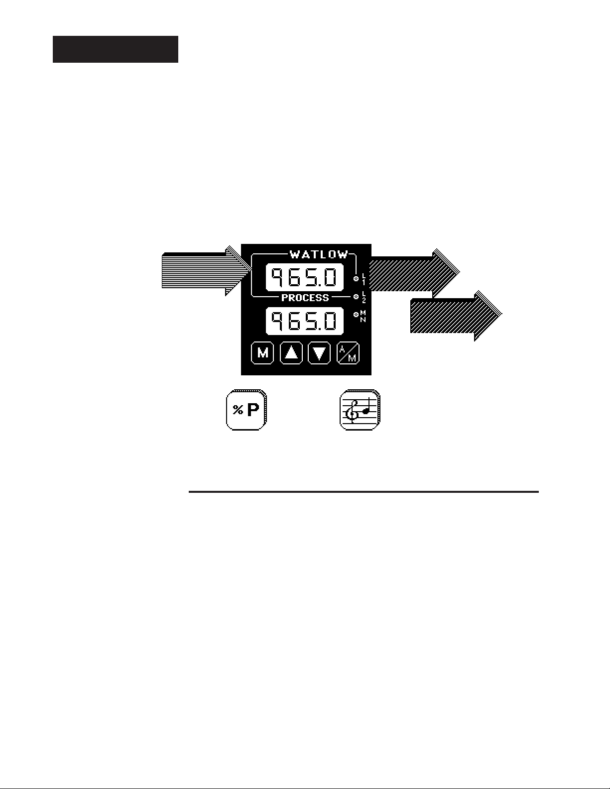
Starting Out With The Watlow Series 965,
A Microprocessor-Based Control
Single Input Type J, K, T, N or S
Thermocouple,
RTD or Process
Figure 1 Series 965 Input and
Output Overview
Output 1 or 2
Percent Power
General Description
Dual Control Output-
PID or on/off, User Selectable
Output 1 Heat or Cool
Output 2 Heat, Cool, Alarm
or None
Auto-tuning
for Heat &
Cool PID
Settings
Welcome to the Watlow Series 965, a 1/16 DIN microprocessor-based temperature control. The 965 has a single input which accepts type J, K, T, N or S
thermocouple, RTD or process input.
With dual output, the primary can be heating or cooling while the secondary can
be a control output opposite the primary output (heat or cool), alarm or none.
Both outputs can be selected as either PID or on/off. PID settings include
proportional band, reset/integral, and rate/derivative. Setting the proportional
band to zero makes the Series 965 a simple on/off control with switching
differential selectable under the HSC parameter.
Special 965 features include the NEMA 4X rating, dual four digit displays in
either red or green, optional low volt power supply, auto-tuning for both heat
and cool outputs, ramp to set point for gradual warm-up of your thermal system,
and automatic/manual capability with bumpless transfer.
Operator-friendly features include automatic LED indicators to aid in monitoring
and setup, as well as a calibration offset at the front panel. The Watlow Series
965 automatically stores all information in a non-volatile memory.
4 Getting Started, Chapter 1
WATLOW Series 965 User's Manual
Page 5
Chapter 2
(
)
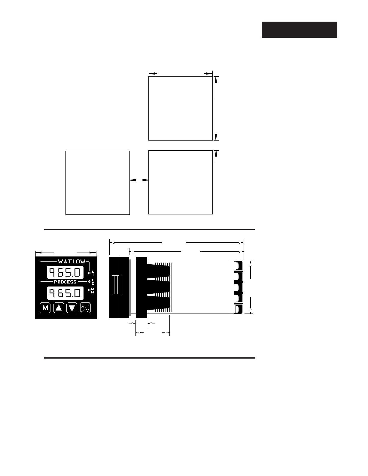
Install and Wire the Series 965
1.77" to 1.79"
(44.96mm to 45.47mm)
Panel Cutout
NOTE:
Measurements
between panel
cutouts are the
minimum
recommended.
0.85"
(20mm)
Your Panel
Thickness
0.06" to 0.38"
(1.5 to 9.7 mm)
1.77" to 1.79"
(44.96mm
to 45.47mm)
0.38"
(9.65mm)
Minimum
Installation
Figure 2 Series 965
Multiple Panel
Cutout Dimensions
4.7"
2.1"
(53 mm)
0.40"
(10mm)
1.21"
31mm
(119mm)
4.1"
(104mm)
Installation Procedure
Follow this procedure to mount the Watlow Series 965 temperature control:
1. Make a panel cutout per the dimensions in Figure 2.
2. Remove the 965 chassis from its case. Holding each side of the bezel,
press in firmly on the side grips until the tabs release. Pull the chassis out
of the case and set aside for later installation.
1.76"
(45mm)
Figure 3 Series 965
Dimensions
NOTE: For rapid
mounting, use
Greenlee punch
#60020 and die
#60021, or hand
hydraulic unit, Kit
#7306. All available
from Grainger.
3. Make sure the rounded side of the external case gasket is facing the panel
surface. Check to see that the gasket is not twisted, and is seated within
the case bezel flush with the panel. Place the case in the cutout you just
made. Make sure the gasket is between the panel cutout and the case
bezel. See Figure 4A.
Install and Wire, Chapter 2
5WATLOW Series 965 User's Manual
Page 6
Installation
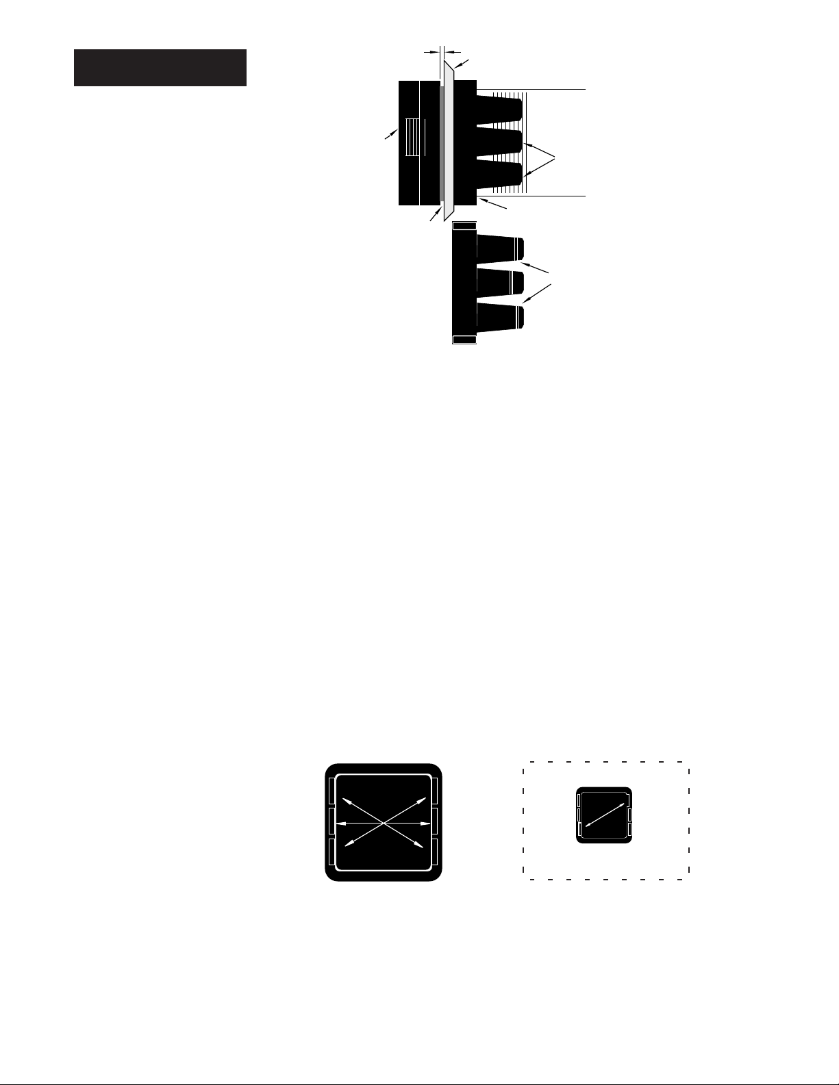
Figure 4 Mounting, Case Side
View & Collar Cross
Section
4A
0 to 0.019 space
(0 to 0.483 mm)
Bezel
Panel
Ridges
Tabs
NOTE:
To guarantee a
proper NEMA 4X
seal, make sure
the gasket
between the panel
and the rim of the
case is not twisted
and is seated
properly.
PRESS FIRMLY.
External Gasket
4B
Mounting Collar
Teeth
Mounting Collar
Cross Section
(notice the offset teeth
on each tab)
4. While pressing the front of the case firmly against the panel, slide the
mounting collar over the back of the control. The tabs on the collar must
line up with the mounting ridges on the case for secure installation. See
Figure 4A again. Slide the collar firmly against the back of the panel getting
it as tight as possible. Make sure you cannot move the case within the
cutout; if you can you do not have a NEMA 4X seal.
Now let's make sure we have a tight seal. Use your thumb to lock the tabs
into place while pressing the case from side to side. Don't be afraid to apply
enough pressure to install the control. The tabs on each side of the collar
have teeth which latch into the ridges. See Figure 4B. Each tooth is staggered at a different height, so only one of the tabs on each side are ever
locked into the ridges at any time.
Looking at Figure 5, you see that the tabs on one side of the collar correspond with those on the opposite side. Make sure that the two corresponding tabs are the only ones locked in the ridges at the same time. If the
matching tabs are not holding the case at the same time you will not have
a NEMA 4X seal. You can make a visual check, or use your finger nail to
pull out on each tab. Only one on each side is engaged, and they must
be corresponding as in Figure 5. The space between the bezel and
panel must be between 0 and 0.019" (0.48 mm).
Figure 5 Case Rear View and
NEMA 4X Seal
Example
WATLOW Series 965 User's Manual
Make sure that the two correspond-
ing tabs below are locked in the
ridges at the same time.
NEMA 4X Seal Example.
When removing the mounting collar, we suggest sliding a thin tool such as
a putty knife or screwdriver under all three tabs on each side at once and
pulling it back off the case.
5. Insert the control chassis into its case and press the bezel to seat it. Make
sure the inside gasket is also seated properly and not twisted. The hardware installation is complete. Proceed to the wiring section from here.
Install and Wire, Chapter 26
Page 7
How to Wire the Series 965
The Series 965 wiring is illustrated by model number option. Check the unit
sticker on the control and compare your model number to those shown here
and also the model number breakdown in the Appendix of this manual.
All outputs are referenced to a de-energized state. The final wiring figure is a
typical system example.
When you apply power without sensor inputs on the terminal strip, the Series
965 displays [----] in the upper display, and a [```0] in the lower display,
except for 0-5VÎ (dc) or 4-20mA process input units. Press the A/M key twice,
and [ER`7] is displayed for one second. This error indicates an open sensor or
A/D error. Remove power to the control and connect the sensor properly, see
pages 8 and 9. All wiring and fusing must conform to the National Electric Code
and to any locally applicable codes as well.
Power Wiring
Ó
WARNING:
To avoid potential
electric shock, use
National Electric
Code (NEC) safety
practices when
wiring and connecting this unit to a
power source and to
electrical sensors or
peripheral devices.
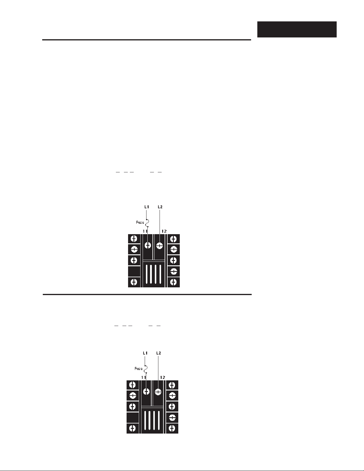
High V oltage
Model # 965A - 3 0 - 00 .
100 to 240 VÅ (ac),
nominal
(85 to 264 actual)
Low V oltage
Model # 965A - 3 1 - 00 .
Ó
12-24V‡ (ac/dc)
NOTE:
Taking the unit out
of the case is not a
normal operating
condition and
should only be done
by a qualified
maintenance
installation technician. Power to the
case should be
disconnected before
removing or installing the controller
into its case.
Figure 6 High Voltage
Power Wiring
Figure 7 Low Voltage
Power Wiring
Install and Wire, Chapter 2
Ó
WARNING:
If high voltage is
applied to the low
voltage unit,
irreversible damage
will occur.
WATLOW Series 965 User's Manual
7
Page 8
Input Wiring
Sensor Installation Guidelines
We suggest you mount the sensor at a location in your process or system
where it reads an average temperature. Put the sensor as near as possible to
the material or space you want to control. Air flow past this sensor should be
moderate. The sensor should be thermally insulated from the sensor mounting.
See Chapter 4 for more information on DIP switch location and orientation.
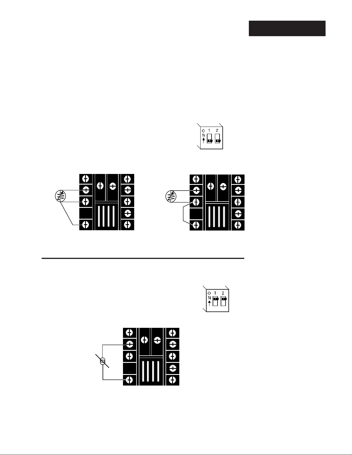
Thermocouple Input
NOTE:
When an external
device with a nonisolated circuit
common is connected to the 420mA or dc output,
you must use an
isolated or ungrounded thermocouple.
Figure 8 Thermocouple
Sensor Input Wiring
ç
CAUTION:
Process input does
not have sensor
break protection.
Outputs can remain
full on.
Extension wire for thermocouples must be of the same alloy as the thermocouple itself to limit errors.
DIP Switch
Orientation
+
3
T/C
-
5
0-5VÎ (dc) Process Input
ç
DIP Switch
Orientation
Figure 9 0-5V
(dc) Process
Î
Sensor Input Wiring
WATLOW Series 965 User's Manual
8
+
V
dc
-35
Input impedance: 10K
Ω
Install and Wire, Chapter 2
Page 9
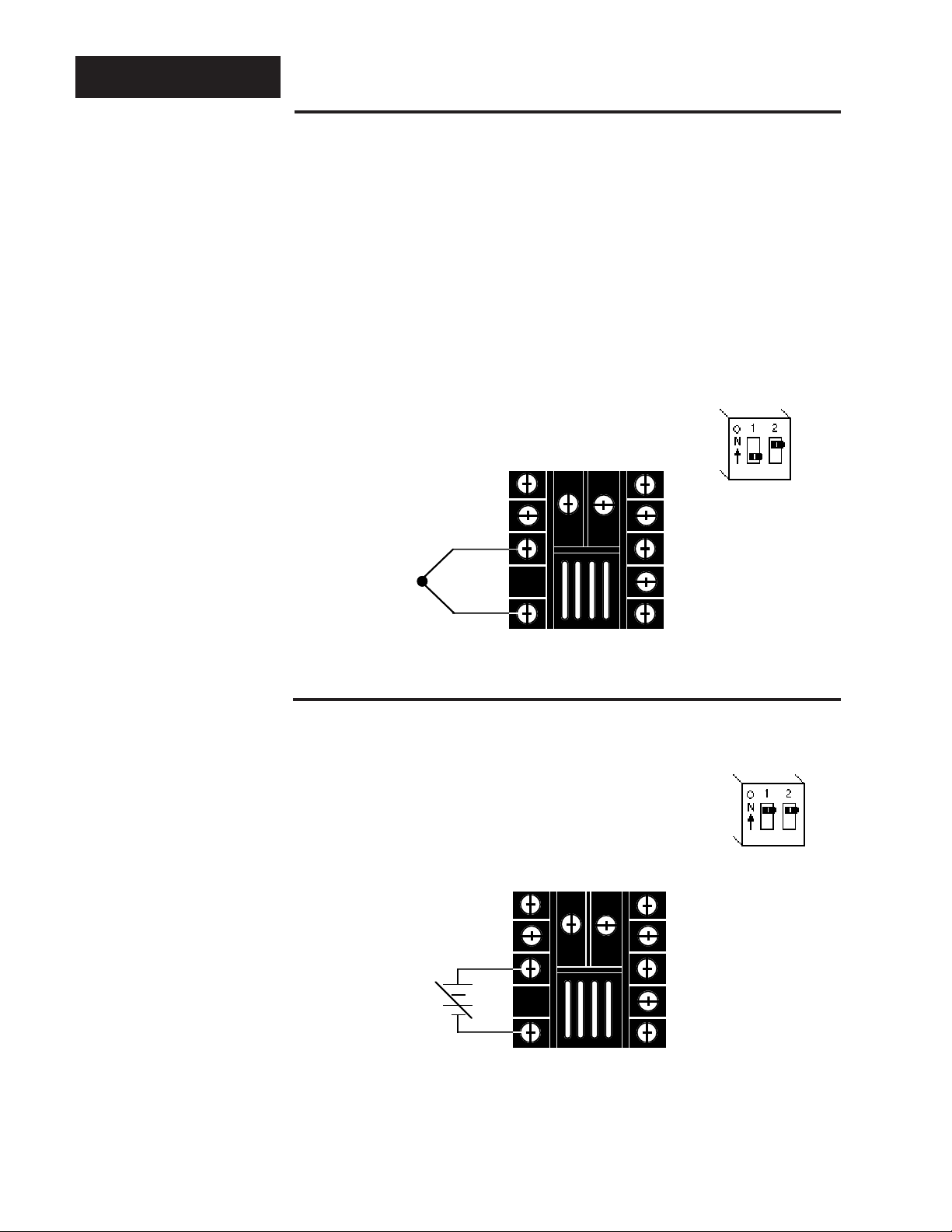
RTD, 2- or 3-wire
There could be a + 2°F input error for every 1Ω of lead length resistance when
using a 2-wire RTD. That resistance, when added to the RTD element resistance, will result in erroneous input to the instrument. To overcome this problem, use a 3-wire RTD sensor, which compensates for lead length resistance.
When extension wire is used for a 3-wire RTD, all wires must have the same
electrical resistance (i.e. same gauge, copper stranded, same length).
DIP Switch
Orientation
S1
3-wire RTD
S2
S3
2
3
2-wire RTD
Jumper
Terminals
5
3 and 5.
S1
S2
S3
2
3
5
Input Wiring
Figure 10 2- or 3-wire RTD
Sensor Input Wiring
4 - 20mA Process Input
I
dc
Install and Wire, Chapter 2
-
2
+
5
Input impedance: 5
ç
ç
CAUTION:
Process input does
not have sensor
DIP Switch
Orientation
Ω
WATLOW Series 965 User's Manual
break protection.
Outputs can remain
full on.
Figure 11 4-20mA Process
Sensor Input Wiring
9
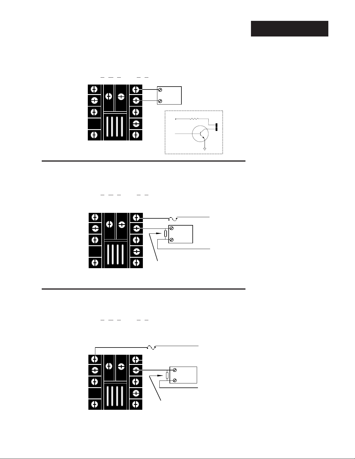
Page 10
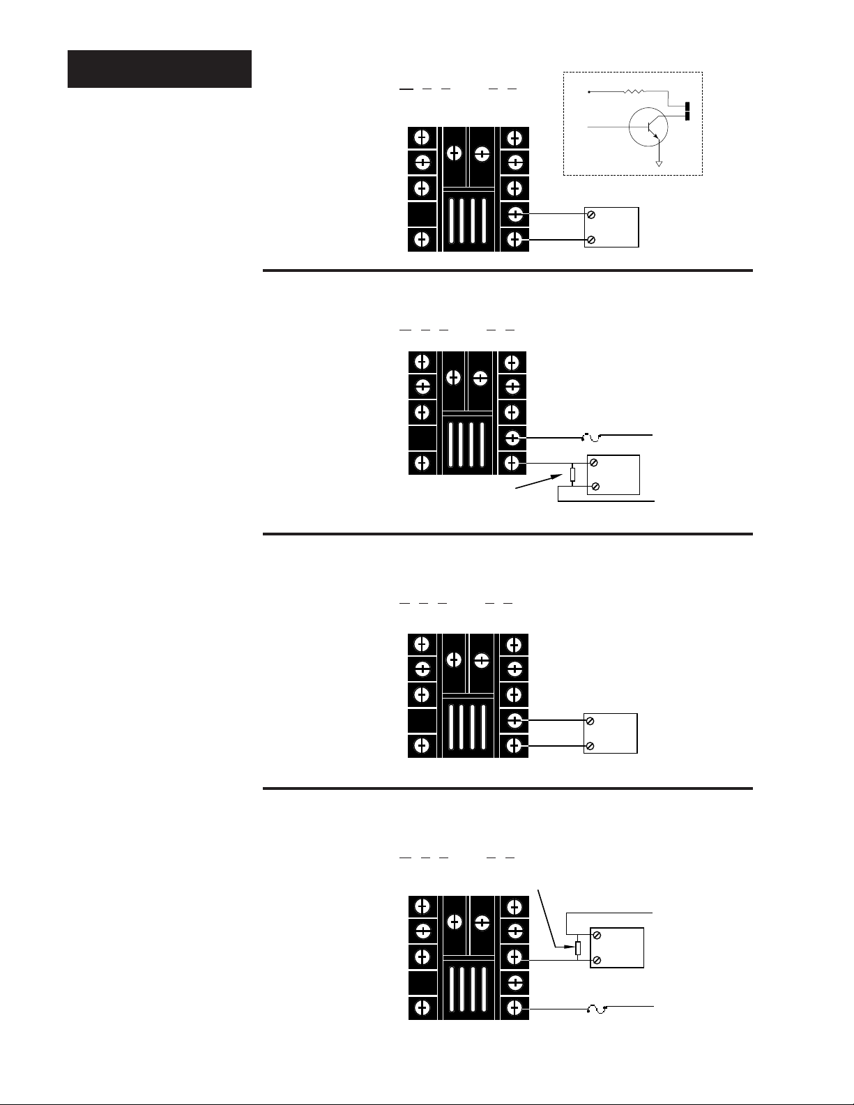
Output 1 Wiring
External
Load
109NO
COM
8 NC
Fuse
L1
L2
Customer Supplied
Quencharc
10
unregulated
V+
V—
9
Internal Circuitry
Figure 12 Switched dc Output
Wiring
Switched DC Output
Model # 965A - 3
C - 00 .
NOTE:
When an external
device with a nonisolated circuit
common is connected
to the 4-20mA or
Switched dc output,
you must use an
isolated or ungrounded thermocouple.
Figure 13 5 Amp Mechanical
Relay Wiring
NOTE:
Switching inductive
loads (relay coils,
solenoids, etc.) with
the mechanical
relay, switched dc or
solid-state relay
output options
requires using an
R.C. suppressor.
Watlow carries the
R.C suppressor
Quencharc brand
name, which is a
trademark of ITW
Pakron. Watlow Part
No. 0804-0147-0000.
Figure 14 4-20mA Process
Wiring
+
9
External
-
10
Load
Mechanical Relay Without Contact Suppression, Form C, 5 Amp
Model # 965A - 3
D - 00 .
Process, 4-20mA
Model # 965A - 3
F - 00 .
+
9
-
10
Maximum load
resistance:
800
Ω
External
Load
Figure 15 -
0.5 Amp Solid-state
Relay Without
Contact Suppression
Wiring
10
Solid-state Relay Without Contact Suppression, 0.5 Amp
Model # 965A - 3
WATLOW Series 965 User's Manual
K - 00 .
Custommer Supplied
Quencharc
8
10
SS1
SS1
L2
External
Load
Fuse
L1
Install and Wire, Chapter 2
Page 11
Output 2 Wiring
7
unregulated
V+
V—
6
Internal Circuitry
Switched DC Output
Model # 965A - 3
C - 00 .
+
6
External
-
7
Load
Mechanical Relay Without Contact Suppression,
Form C, 5 Amp
Model # 965A - 3 D - 00 .
1NC
6
7
Customer Supplied
COM
NO
Quencharc
Fuse
External
L1
Load
L2
Solid-state Relay Without Contact Suppression, 0.5 Amp
Model # 965A - 3
K - 00 .
NOTE:
For more information on alarms see
page 24.
Figure 16 Switched dc Output
Wiring
Figure 17 5 Amp Mechanical
Relay Wiring
NOTE:
Switching inductive
loads (relay coils,
solenoids, etc.) with
the mechanical
relay, switched dc or
solid-state relay
output options
requires using an
RC suppressor.
Watlow carries the
RC suppressor
Quencharc brand
name, which is a
trademark of ITW
Pakron. Watlow Part
No. 0804-0147-0000.
Install and Wire, Chapter 2
SS2
1
Fuse
L1
NOTE:
Output is in open
State in Alarm
Condition.
7
SS2
External
Load
L2
Figure 18 -
0.5 Amp Solid-state
Relay Without
Customer Supplied
Custommer Supplied
Quencharc
Quencharc
WATLOW Series 965 User's Manual
Contact Suppression Wiring
11
Page 12
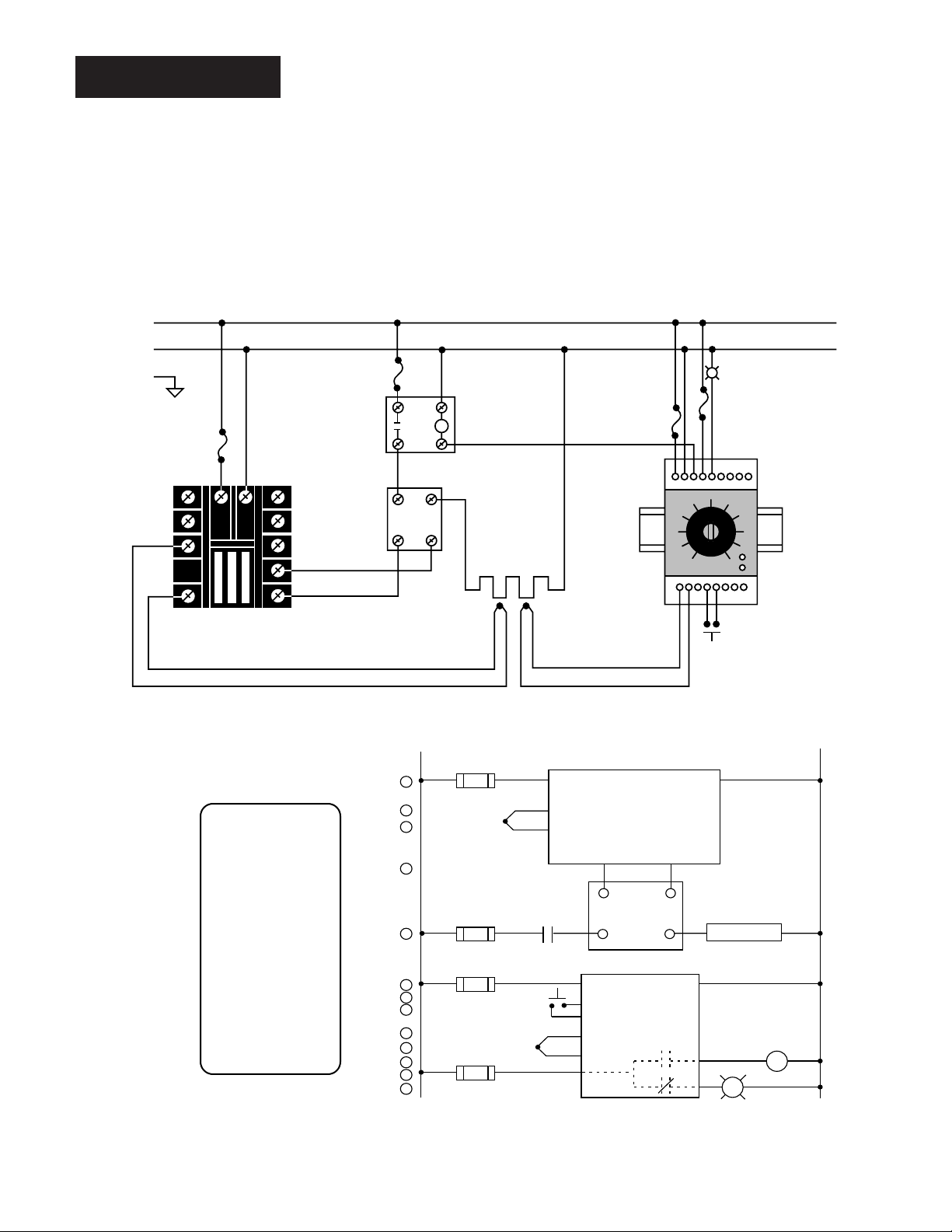
Wiring Example
1
120VÅ (VAC)
L1
L2
2
3
5
4
5
1 2
1
2
(+)
(-)
3
11
18
12
13
14
15
2
1CR
16
High Temperature
Light
1
2
3
4
8
9
10
11
12
R
SSR-240-10A-DC1
DC Input Solid-state Relay
17
1
8
Heater
(+)
(-)
1 CR-1
910
2
910
67
11 12
5
6
7
Limit Control
Series 965
965A-3CA0-0000
Temperature control
Series 92
92A3-1DJ1-0000
13
4
3
5
11
12
13
14
10
(+)
(-)
3-32V
Î
(dc)
In
Out
24-240V
Å
(ac)
Figure 19 System Wiring
Example
L1
120VÅ (VAC)
L2
Earth Ground
Fuse
ÓWARNING:
All wiring and fusing must conform to the National Electric Code NFPA70. Contact
your local board for additional information. Failure to observe NEC safety guidelines could result in injury to personnel or damage to property.
ç CAUTION:
Watlow mercury relay loads must have a unity power factor.
For RESISTIVE LOADS ONLY.
High Temperature
Light
Coil
High Limit
Mechanical
Controller
3 (+)
5 (-)
11 12
Red
965A-3CA0-0000
Rear View
SSR-240-10A-DC1
dc Input
SSR
9 +
10 -
Process Sensor
Out
2
1
3
4
Limit Control
In
Heater
13 14
11
10
-
+
92A3-1DJ1-0000
Limit Sensor
Optional
Normally Open
Momentary Switch
965A-3CA0-0000
1 Not Used
2 S1, I3 S2, TC+, V+
4 Not Used
5 S3, TC-, V-, I+
6 Not Used
7 Not Used
8 Not Used
9 DC +1
10 DC -1
11 L1
12 L2
WATLOW Series 965 User's Manual
12
Install and Wire, Chapter 2
Page 13
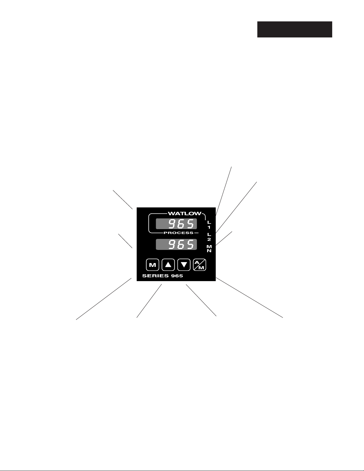
Chapter 3
How to Use the Keys and Displays
After one minute with no key activations, the control reverts to the process
value in the upper display and the set point in the lower display.
Keys/Displays
Figure 20 Series 965 Keys
and Displays
Upper Display
Red or green, 0.3" (8 mm) high, seven segment,
four digit LED display, indicating either process,
actual temperature, the operating parameter values or an open sensor. When powering up, the
Process display will be blank for five seconds.
This display can be blank by setting [`dSP] to
[`SEt]. See page 18.
Lower Display
Red or green, 0.3" (8 mm)
high, seven-segment, fourdigit LED display, indicating
the set point, output value,
parameters for data in the
upper display, or error and
alarm codes. This display can
be blank by setting [`dSP] to
[`Pro]. See page 18.
L1
When lit, this LED
tells you when Output 1 is energized.
L2
When lit, this LED tells
you when Output 2 is
active. This output can
be configured as a control or alarm output.
MN
Lit when the control is in Manual operation. Press the A/M key twice to
enter Automatic operation. When
blinking, this indicates that pressing
the A/M key toggles between Auto
and Manual. After five seconds without pressing the A/M key, the LED
stops blinking, and returns to its previous state.
Mode Key
Steps the control through
the Operating Menu; also,
in the Auto mode, new data
is self entering in five seconds.
Keys & Displays, Chapter 3 WATLOW Series 965 User's Manual
Up-arrow Key
Increases the value of the
displayed parameter. A
light touch increases the
value by one. Holding the
key down increases the
value at a rapid rate. New
data is self entering in
five seconds.
Up-arrow/Down-arrow Keys
When pressed simultaneously for three seconds, the
Setup Menu appears displaying the [`LOC] parameter.
Continue to press the Up-arrow/Down-arrow keys, and
the Calibration Menu appears.
Down-arrow Key
Decreases the value of
the displayed parameter.
A light touch decreases
the value by one. Holding
the key down decreases
the displayed value at a
rapid rate. New data is
self entering in five seconds.
A/M Key
Pressed once, it clears
any latched alarms and
toggles between Auto
and Manual mode. If
pressed again within five
seconds it will change
from Auto to Manual or
vice versa. While in
Manual mode, percent
power is in the lower display.
13
Page 14

Setup
Ó
WARNING:
Remove power from
the control before
removing the
chassis from the
case or changing
the DIP switches.
Chapter 4
How To Set Up The Series 965
Setting up the Series 965 is a simple process. First set the DIP switches to
match your input type. Refer to the orientation below and Page 16 for the In
parameter. Next, configure the 965's features to your application in the Setup
Menu, then enter values in the Operating Menu. Both tasks use the MODE key
to move through the menus and the Up-arrow/Down-arrow keys to select data.
Before entering information in the Setup menu, set the dFL parameter.
If selected as US: °F, proportion band in degrees, reset rate are the defaults.
If selected as SI: °C, proportional band in % of span, derivative and integral
are the defaults. Changing the dFL prompt will set parameters to their
factory default. Document all current parameter settings first. See
Appendix 2 in the calibration section to change this parameter.
How to Set the Input Type DIP Switch
The Series 965 input type can be user selectable at any time via a Dual In-line
Package (DIP) switch inside the control, located on the left (viewed from the
bottom). To set the DIP switch, remove the control chassis from the case.
Holding each side of the bezel, press in firmly on the side grips until the tabs
release. You may need to rock the bezel back and forth several times to
release the chassis.
The locations of the board and switches appear in Figure 21. Refer to the input
types below for DIP switch orientation. DIP switch selection must match the
sensor selected under the In parameter in the Setup Menu. Set the software
selection for the input type to match. See Page 16.
Figure 21 DIP Switch Location
and Orientation
14
WATLOW Series 965 User's Manual
Control Chassis -
Bottom View
Input Types
Thermocouple RTD Process
Setup, Chapter 4
Page 15

w
h
n
g
e
Entering the Setup Menu
The Setup Menu displays the parameters that configure the Series 965's features
to your application.
Enter the Setup Menu by pressing the Up-arrow and Down-arrow keys simultaneously for 3 seconds. The lower display shows the LOC parameter, and the
upper display shows its current level. All keys are inactive until you release both
keys. You can reach the LOC parameter from anywhere.
Setup
Figure 22 Entering the Setup
Menu
You will not see all parameters in this menu, depending on the unit's configuration and model number. After stepping through the menu it returns to the control
set point parameter under the Operation Menu.
= Parameter may or may not
appear depending on your
control configuration.
75
( )
Output 2 alarm hysteresis
Output 2 hysteresis
( )
Latching for alarm
( )
Silence alarm
( )
RTD calibration curve
( )
Ramp functio
( )
Ramp rate
( )
% Power limitin
( )
Display
HSA
LAt
SIL
rtd
rP
rt
PL
dSP
Control Set Point
LOC
In
dEC
C _ F
rL
rH
Ot 1
HSC
Ot2
( )
( )
( )
( )
( )
( )
( )
( )
( )
M
Mode Key
User lock out
Input type
Decimal plac
Celcius__Fahrenheit
Range lo
Range hig
Output 1
Control hysteresis
Output 2
NOTE:
While in the Setup
Menu, all outputs
are off.
Figure 23 The Setup Menu
Setup, Chapter 4
WATLOW Series 965 User's Manual
15
Page 16

Setup
Setup Parameters
When you are at the top of the menu, the Series 965 displays the user level of
operation in the upper display, and the LOC parameter in the lower display.
Press the MODE key and the value of the next parameter appears in the upper
display, and the parameter appears in the lower display.
LOC
NOTE:
Set the LOC parameter value as the
final step in programming the
Series 965 controller to prevent
locking yourself out
of the Operations
and Setup Menu
during initial
programming.
NOTE:
Process input does
not have sensor
break protection or
bumpless transfer.
Lock: Selects the level of operator lock-out as defined below.
Range: 0 - 4 Default: 0
LOC 0: All operating parameters may be viewed or changed. Manual operation
is permitted. When in manual operation, percent power is adjustable. Bumpless
transfer to manual mode can occur on sensor break.
LOC 1: The set point, actual, and alarm settings are the only visible parameters,
set point is adjustable in this level. Manual operation and auto-tune are permitted. When in manual operation, percent power is adjustable. Bumpless transfer
to manual mode can occur on sensor break.
LOC 2: The set point, actual, and alarm settings are the only visible parameters,
set point is adjustable in this level. Manual operation is permitted. When in
manual operation, percent power is adjustable. Bumpless transfer to manual
mode can occur on sensor break.
LOC 3: The set point and actual are the only visible parameters, set point is
adjustable in this level. Manual operation is not permitted. Bumpless transfer is
defeated and outputs are disabled on sensor break.
LOC 4: The set point and actual are the only visible parameters, set point is not
adjustable in this level of lock-out. Manual operation is not permitted. Bumpless
transfer is defeated and outputs are disabled on sensor break.
16
In
Input: Selects the sensor input type. The internal DIP switch must also match
the In parameter. See Figure 21 on Page 14 for DIP switch orientation, and see
Table 1 on Page 18 for input type temperature ranges.
Range: J, K (appears as H), t, n, S, rtd, rt.d, 0-5, 420 Default: J
dEC
Decimal: Selects the location of the decimal point for all process related data.
This parameter only appears if the In parameter is 0-5 or 420. Make sure the
internal DIP switch matches the In parameter.
Range: 0, 0.0, 0.00 Default: 0
C _ F
Celsius _ Fahrenheit: Selects the units of temperature measurement for the
control. This parameter only appears if the In parameter is a thermocouple or
RTD input. The default is dependent on the dFL parameter located in the Calibration menu. Refer to the Appendix. Range: C or F
If dFL = US: Default: F If dFL = SI: Default: C
rL
Range Low: Selects the low limit of the set point. Also used to set the low end
of the process input. 0.0VÎ (VDC) and 4mA represent Range Low (rL) for
process input. The process input is linearly scaled between rL and rH. See the
model number and specification in the Appendix for range values, or refer to
Table 1 on Page 18. Range: Sensor range low to rH
Default: Low limit of sensor type/-500 for process input
WATLOW Series 965 User's Manual
Setup, Chapter 4
Page 17

Setup
Range High: Selects the high limit of the operating range. Also used to set the
high end of the process input. 5.0VÎ (dc) and 20mA represent Range High (rH)
for process input. The process input is linearly scaled between rL and rH. See
the model number and specification information in the Appendix for your range
values, or refer to Table 1 on Page 18. Range: Sensor range high to rL Default:
High limit of sensor type/9999 for process input
Output 1: Selects the action for the primary output. Action in response to the
difference between set point and process variable. Select ht (heat) for reverse
acting or select CL (cool) for direct acting. Range: ht, CL Default: ht
Hysteresis-Control: Selects the switching hysteresis for Output 1 and 2 when
you select 0 (ON/OFF) under the Pb1 parameter and Ot2 = Con.
Range: 1 to 99, 0.1 to 9.9, 0.01 to 0.99/1 to 55, 0.1 to 5.5, 0.01 to 0.55
Default: 3, 0.3, 0.03°F/2, 0.2, 0.02
Output 2: Selects the output action for the secondary output.
Range: Con Control mode opposite Output 1 (heat or cool) Default: Con
PrA Process alarm with alarm message displayed
Pr Process alarm with no alarm message displayed
dEA Deviation alarm with alarm message displayed
dE Deviation alarm with no alarm message displayed
no None
Hysteresis - Alarm: Selects the switching hysteresis for Output 2 when Ot2 is an
alarm. This parameter only appears if Ot2 ≠ Con or no. See Page 19 for the Pb1
parameter. Range: 1 to 9999, 0.1 to 999.9, 0.01 to 99.99/1 to 5555, 0.1 to 555.5,
0.01 to 55.5 Default: 3, 0.3, 0.03/2, 0.2, 0.02
rH
Ot1
HSC
Ot2
HSA
Latching: Selects whether the alarm is latching or non-latching. Latching alarms
must be cleared before the alarm output will reset. Non-latching automatically
resets the alarm output when the condition clears. This parameter will not appear
if Ot2 = Con or no. Range: LAt or nLA Default: nLA
Silencing: Selects alarm silencing (inhibit) for the alarm. This parameter appears
only when Ot2 = dEA or dE. For more information see Chapter 5, "Using Alarms."
Range: On or OFF Default: OFF
RTD: Selects the RTD calibration curve for RTD inputs. This parameter
will not appear unless In = rtd or rt.d. JIS = 0.003916Ω/Ω°C,
DIN = 0.003850Ω/Ω°C. Range: din or JIS Default: din
Ramping: Choose Str, and the set point ramps at the selected rate in °/hr from
process (actual) temperature to set point, when power is applied to the control
(start up). It will not ramp with a set point change. On is the same as Str plus it
ramps
at the selected ramp rate. OFF is for no ramping action. When ramping, the lower
display alternately flashes rP. The set point displayed is the desired end set point.
The ramping setpoint is not shown. Entering the Setup menu or manual operation
disables the outputs and ramp. Once you exit either one, the 965 controls to the
last entered set point. Range: Str, On, OFF Default: OFF
Rate: Selects the ramping rate in degrees per hour. This parameter will not
appear if rP = OFF. Range: 0 to 9999 Default: 100°/hr
with
a set point change. It ramps from the previous set point to a new one
LAt
SIL
rtd
r P
r t
Setup, Chapter 4
WATLOW Series 965 User's Manual
17
Page 18

Setup
P L
Range: Dependent on output type. -100 to100 Default: 100
Display: Selects which displays are active or viewable. Five seconds after
Power Limiting: The power limiting function in % power for heat.
dSP
selected, the appropriate display goes blank. Press MODE, Up-arrow or
Down-arrow to override this feature and cause the current value to be displayed for 5 seconds.
Range: nor Normal displays Default: nor
SEt Set Point - Lower display only
Pro Process - Upper display only
Table 1 Input Ranges.
Table 2 Setup Menu
Prompts and
Descriptions.
Input Type Sensor Range Low Sensor Range High
J32°F/0°C 1382°F/750°C
K (appears as H) -328°F/-200°C 2282°F/1250°C
t -328°F/-200°C 662°F/350°C
n32°F/0°C 2282°F/1250°C
S32°F/0°C 2642°F/1450°C
rtd (1°) -328°F/-200°C 1292°F/700°C
rt.d (0.1°) -199.9/199.9 999.9/700.0
4-20mA 4mA/-999 units 20mA/9999 units
VÎ (dc) 0VÎ (dc)/-999 units 5VÎ (dc)/9999 units
0-5
Setup Menu
Do not enter any values here; make photocopies instead.
Parameter Value Range Factory Default Appears If:
LOC 0 - 4 0
In J, K (appears as H), t, n, S, rtd, J DIP switch
rt.d, 0-5, 420 selectable.
dEC 0, 0.0, 0.00 0 In = 0-5 or 420
C _ F C or F Dependent on dFL. In = J,K,t,n,S,rtd,rt.d
rL rL to rH Input dependent.
rH rH to rL Input dependent.
Ot1 ht or CL ht
HSC 1 - 99, 0.1 - 9.9, 0.01 - 0.99 3, 0.3, 0.03
1 to 55, 0.1 to 5.5, 0.01 to 0.55 3, 0.3, 0.03/2, 0.2, 0.02
Ot2 Con = Control Con
PrA = Process Alarm
Pr = Process with no alarm message
dEA = Deviation alarm
dE = Deviation with no alarm message
no = None
HSA 1 - 9999, 0.1 - 999.9, 0.01 - 99.99 3, 0.3, 0.03°F Ot2 ≠ Con or no
1 - 5555, 0.1 - 555.5, 0.01 - 55.55 2, 0.2, 0.02°C
LAt LAt or nLA nLA Ot2 ≠ Con or no
SIL On or OFF OFF Ot2 = dEA or dE
rtd JIS or din din In = rtd or rt.d
r P Str = Ramping on power up OFF
rt 0 to 9999 100°/hr rP ≠ OFF
P L 0 to 100 100
dSP nor = normal nor
18
WATLOW Series 965 User's Manual
on = Ramping to set point at all times
OFF = None
SEt = Set Point (lower only)
Pro = Process (upper only)
Setup, Chapter 4
Page 19

Operation
= Prompt appears or not according
to control configuration.
M
75
Pb1
rE1/It1
rA1/dE1
Ct1
Pb2
Control Set Point
( )
Proportional band 1
( )
Reset 1/Integral
( )
Rate 1/Deviative 1
( )
Cycle time 1
( )
Proportional band 2
rE2/It2
rA2/dE2
Ct2
ALO
AHI
CAL
AUt
( )
Reset 1/Integral 1
( )
Rate 2/Deviative 2
( )
Cycle time 2
Alarm low
( )
( )
Alarm high
( )
Calibration offset
( )
Auto-tune
Operation Parameters
Set Point: Sets the operating set point for Output 1. Represents the process
value the system tries to achieve for Output 1. "SP" does not appear, the control set point value will. The lower display may be blank if dSP = Pro. If in a
ramping mode, the lower display alternately flashes the desired end set point
and rP.
NOTE:
The upper display
will always return to
the process value
after 1 minute
without key strokes.
Figure 24 The Operation Menu.
[
SP
]
Proportional Band 1 & 2 : A proportional band expressed in degrees or % of
span, within which a proportioning function is active for Output 1 or 2. When
Pb1 = 0, the unit functions as an on/off control on Output 1 and 2. Pb2 will not
appear if Pb1 = 0 or Ot2 ≠ Con. The switching differential is determined by the
HSC parameter.
If dFL = US: Range Pb1: 0 to 999°F/0 to 555°C/0 to 999 Units; 0.0 to 9.9°F/
0.0 to 5.5°C/0.0 to 9.9 units, Pb2: The same as Pb1 except lower limit is 1.
Defaults:
If dFL = SI: Range: 0 to 999.9% of span Defaults:
Pb1 =
25°F/2.5°F
Pb2 =
25
Pb1 =
3.0%
Pb2 =
3.0%
Reset /Integral 1 & 2: An integral control action for Output 1 or 2 that automatically eliminates offset, or "droop," between set point and actual process
temperature. rE1/It1: Will not appear if Pb1 = 0. rE2/It2: Appears if Pb1 ≠ 0
and Ot2 = Con. Either reset (rE) or integral (It) will appear depending on how
the dFL parameter is set in the Calibration menu. See Appendix II.
If dFL = US: Range: 0 to 9.99 repeats/minute Default: 0.00
If dFL = SI: Range: 00.1 to 9.99 minutes per repeat Default: 0.00
Rate /Derivative 1 & 2 : The rate (derivative) function for Output 1 or Output
2. Eliminate over shoot on start up, or after the set point changes. rA1/dE1:
Will not appear if Pb1 = 0. rA2/dE2: Appears if Pb1 ≠ 0 and Ot2 = Con.
Either rate (rA) or derivative (dE) appears depending on how dFL is set in the
Calibration menu. If dFL = US or SI: Range: 0 to 9.99 minutes Default: 0.00
Cycle Time 1 & 2: Time for a controller to complete one time proportioned
cycle for Output 1 or Output 2; expressed in seconds. Ct1: Will not appear if
Pb1 = 0, or Output 1 is 4-20mA. Ct2: Will not appear if Pb1 = 0 or Ot2 ≠ Con.
If a mechanical relay or contactor is switching power to the load, a longer
cycle time may be desirable to minimize wear on the mechanical components. Typical life of a mechanical relay is 100,000 cycles.
Range: 0.1 to 999.9 Default: 5.0
Pb1
Pb2
rE1/It1
rE2/It2
rA1/dE1
rA2/dE2
Ct1
Ct2
Setup, Chapter 4
WATLOW Series 965 User's Manual
19
Page 20

Operation
ALO
AHI
CAL
AUt
Table 3 Operation Menu
Prompts and
Descriptions.
Alarm Low: Represents the low process alarm or low deviation alarm. This
parameter will not appear if Ot 2 = no or Con.
If Ot2 = dEA or dE: Range: -999 to 0 Default: -999
If Ot2 = PrA or Pr: Range: rL to AHI Default: rL
Alarm High: Represents the high process alarm or high deviation alarm. This
parameter will not appear if Ot2 = no or Con.
If Ot2 = dEA or dE: Range: 0 to 999 Default: 999
If Ot2 = PrA or Pr: Range: ALO to rH Default: rH
Calibration Offset: Adds or subtracts degrees from the input signal.
Range: -180°F to 180°F/-100°C to 100°C/-180 units to 180 units; or
-18.0°F to 18.0°F/-10.0°C to 10.0°C Default: 0
Auto-Tune: Initiates auto-tune.
Range: 0 = off, 1 = slow, 2 = medium, 3 = fast Default: 0
Operation Menu
Use this page as a master copy for your Series 965 Operation Parameters.
Do not enter any values here; make photocopies instead.
Operation Parameters Value Range Factory Default
Pb1 If dFL = US:
0 - 999°F/0 - 555°C/0 - 999 Units 25°F
0 - 99.9°F/0 - 55.5°C/0 - 99.9 Units 2.5°F
0=ON/OFF control. HSC =switch diff.
If dFL = SI:
0.0 to 999.9% of span 3%
rE1 0.00 to 9.99 repeats/minute 0.00 repeats/minute
0.00 = No Reset. Won't appear if Pb1 = 0
or dFL = SI.
It1 0.0 - 99.9 minutes/rpt. 0.00 = No Integral. 00.0 minutes/repeat
Won't appear if Pb1 = 0 or dFL = US.
rA1 0.00 to 9.99 minutes 0.00 minutes
0.00 = No Rate. Will not appear if Pb1 = 0
or dFL = SI.
dE1 0.00 - 9.99 minutes. 0.00 = No Derivative. 0.00 minutes
Won't appear if Pb 1 = 0 or dFL = US.
Ct1 0.1 to 999.9 5.0 seconds
Won't appear if Pb1 = 0, or 4-20mA.
Pb2 Same as Pb1. Pb2 lower limit = 1, 0.1, 0.01
rE2 Same range as rE1.
It2 Same range as It1.
rA2 Same range as rA1.
dE2 Same range as dE1.
Ct2 Same range as Ct1.
ALO - Deviation dE -999 to 0 -999
Process Pr rL to AHI rL
Will not appear if Ot2 = no or Con.
AHI - Deviation dE 0 to 999 999
Process Pr ALO to rH rH
Will not appear if Ot2 = no or Con.
CAL ±18°F/±10°C/±18 Units 0
AUt 0-3 0
20
WATLOW Series 965 User's Manual
Setup, Chapter 4
Page 21

Chapter 5
How to Tune and Operate
Auto-tuning (Heat and/or Cool)
The Series 965 can automatically tune the PID parameters to fit the characteristics of your particular thermal system.
The auto-tuning procedure operates on a thermal response value — slow,
medium, or fast. Use the slow thermal response when your process does not
need to reach set point too rapidly, or if it usually does not often exceed set
point. A fast thermal response produces a rapid temperature change over a
short period of time.
Once the auto-tune sequence has begun, the Output 1 heat proportional band
is set to 0 and the control goes into an on/off mode of control at 90% of the
established set point. The displayed set point remains unchanged.
Tuning
NOTE:
Set the HSC parameter under the Setup
Menu to 3
before auto-tuning
your control.
°F/2°C
Once the control finishes "learning" the system, it returns to a standard PID
control with the PID values automatically set as a result of auto-tuning. See
Manual Tuning on the next page to set the cool PID parameters. Any change
of the set point, while in auto-tune, re-initiates the auto-tune procedure.
Auto-tuning at a Set Point of 200°F
200
180
°Temp
100
Auto-tune
Begins
Process
90% of
Set Point
°Time
Auto-tune
Complete
Set Point
Figure 25 Auto-tuning at a
Set Point of 200
°F.
In order for the 965 to successfully complete auto-tune, the process must cross
90% of set point four times within 80 minutes after auto-tune has started. If this
does not happen within the 80 minute time limit, the Pb remains at 0 and the
control functions in an on/off mode.
Tuning and Operating, Chapter 5
WATLOW Series 965 User's Manual
21
Page 22

Tuning
To start auto-tuning:
1. Press the MODE key until the AUt prompt appears in the data display.
2. Select a thermal response value, 1=slow, 2=medium, and 3=fast, using
the Up-arrow/Down-arrow keys. A thermal response value of 2 satisfactorily tunes most thermal systems.
3. Press the MODE key. While the control is in the tuning mode, the lower
display alternately displays the normal information and the prompt At. The
time between alternations is 1 second.
4. When tuning is complete, the displays return to their previous state and
AUt reverts to 0. The 965 installs appropriate PID tuning parameters and
saves them in the non-volatile memory. If a mechanical relay or
contactor is switching power to the load, a longer cycle time may be
desirable to minimize wear on the mechanical components. Typical
life of a mechanical relay is 100,000 cycles.
To abort auto-tuning either reset the AUt parameter to 0, press the A/M key
twice, or cycle power off and on. In all cases, aborting auto-tune restores all
values to those previous to auto-tuning.
Manual Tuning
For optimum control performance, tune the Series 965 to your thermal system.
The tuning settings here are for a broad spectrum of applications; your system
may have somewhat different requirements. NOTE: This is a slow procedure,
taking from minutes to hours to obtain optimum value.
NOTE:
Tune heating outputs at a set point
Tune cooling outputs at a set point
1. Apply power to the Series 965 and enter a set point. Begin with these
Operation parameters: Pb = 1, rE/It = 0.00, rA/dE = 0.00, Ct = 5.0, CAL = 0,
AUt= 0.
2. Proportional Band Adjustment: Gradually increase Pb until the upper
display temperature stabilizes to a constant value. The process temperature
will not be right on set point because the initial reset value is 0.00 repeats per
minute. (When Pb = 0; rE/It and rA/dE1 are inoperative, and the 965 functions as a simple ON/OFF control.) The HSC parameter determines the
switching differential value.
3. Reset/Integral Adjustment: Gradually increase rE, or decrease It until the
upper display temperature begins to oscillate or "hunt." Then slowly decrease
rE or increase It until the upper display stabilizes again near set point.
above ambient temperature.
below ambient temperature.
22
WATLOW Series 965 User's Manual
4. Cycle Time Adjustment: Set Ct as required. Faster cycle times sometimes
achieve the best system control. However, if a mechanical contactor or
solenoid is switching power to the load, a longer cycle time may be desirable
Tuning and Operating, Chapter 5
Page 23

to minimize wear on the mechanical components. Experiment until the
cycle time is consistent with the quality of control you want. Ct will not
appear on units with a process output.
5. Rate/Derivative Adjustment: Increase rA/dE to 1.00 minute. Then raise
set point by 20° to 30°F, or 11° to 17°C. Observe the system's approach to
set point. If the load temperature overshoots set point, increase rA/dE to
2.00 minutes.
Raise set point by 20 to 30°F, or 11 to 17°C and watch the approach to the
new set point. If you increase rA/dE1 too much, approach to set point is
very sluggish. Repeat as necessary until the system rises to the new set
point without overshooting or approaching the set point too slowly.
6. Calibration Offset Adjustment: You may want your system to control to
a temperature other than the value coming from the input sensor. If so,
measure the difference between that temperature (perhaps at another point
in the system) and the process value showing in the upper display. Then
enter the CAL offset value you want. Calibration offset adds or subtracts
degrees from the value of the input signal.
Manual and Automatic Operation
To change from auto to manual operation, press the A/M key twice.
Manual operation provides open loop control of the outputs from a range of
-100% (full cooling) to 100% (full heating) power. The 965 allows a negative
output value only with a Cl (Cool) selection on either Ot1 or Ot2 = Con. Automatic operation provides closed loop on/off or PID control. When the operator
transfers from a closed loop to an open loop, the 965 retains the power level
from the closed loop control, referred to as bumpless transfer. When the 965
returns to closed loop control, it restores the previous set point temperature.
Tuning/Operation
NOTE:
Process input does
not have sensor
break protection or
bumpless transfer.
Outputs selected as
Ht (reverse acting)
will be full on if
sensor break
occurs.
The MN LED indicates auto or manual operation. When the LED is on, the
control is in manual operation. When the LED is off, it is in automatic operation.
When the LED flashes, press the key again within five seconds to complete the
change in operation.
When a sensor opens, the 965 switches from automatic to manual operation if
LOC = 0, 1 or 2.
• If LOC = 0, 1 or 2 and the bumpless transfer conditions are met, process has
stabilized at a ± 5% power level for a 2 minute period prior to sensor break
provided the power level is less than 75%. The 965 switches to manual
operation at the last automatic power level.
• If LOC = 3 or 4, the 965 switches into manual operation at 0% power (outputs
disabled).
When transferring from auto to manual operation, the control output(s) remains
stable ("bumpless," smooth transition). When transferring from manual to
automatic operation, the control output(s) may change significantly. In manual
operation, the output value appears in the lower display; in automatic operation,
the set point appears.
Tuning and Operating, Chapter 5
WATLOW Series 965 User's Manual
23
Page 24

Auto/Man-Alarms
Using Alarms
The Series 965 has two alarm types, Process or Deviation. A process alarm
sets an absolute temperature. When the process exceeds that absolute temperature limit an alarm occurs. The process alarm set points may be independently
NOTE:
When the alarm
output is deenergized, the NO
contact is open in
the alarm condition.
set high and low. Under the Setup Menu, select the type of alarm output with the
Ot2 parameter. PrA = Process Alarm Pr = Process alarm with no alarm
message displayed
A Deviation alarm alerts the operator when the process strays too far from set
point. The operator can enter independent high and low alarm settings. The
reference for the deviation alarm is the set point. Any change in set point causes
a corresponding shift in the deviation alarm. dEA = Deviation Alarm
dE = Deviation alarm with no alarm message displayed
Example: If your set point is 100°F/38°C, and a deviation alarm is set at +7°F/
4°C as the high limit, and -5°F/3°C as the low limit, the high alarm trips at 107°F/
41.6°C, and the low alarm at 95°F/35°C. If you change the set point to 130°F/
54.4°C, the alarms follow the set point and trip at 137°F/59°C and 125°F/51.6°C.
Under the Setup Menu, select the type of alarm output with the Ot2 parameter.
dEA = Deviation Alarm dE = Deviation alarm with no alarm message displayed
Figure 26 Alarm Display
Examples
Both process and deviation alarms can be latching or non-latching. When the
alarm condition is removed a non-latching alarm automatically clears the alarm
output. You must manually clear a latching alarm before it will disappear.
Flashing "LO" or "HI" in the lower display indicates an alarm when Ot2 = PrA or
dEA. The lower display alternately shows information from the current parameter
and the "LO" or "HI" alarm message at one second intervals. The alarm output is
de-energized and the L2 LED is lit.
To clear an alarm…
• First correct the alarm condition, then…
• If the alarm is latching…
Clear it manually; press the A/M key once as soon as the process
temperature is inside the HSA parameter alarm limit.
• If the alarm is non-latching…
The alarm clears itself automatically as soon as the process
temperature is inside the HSA parameter alarm limit.
Press once -
Clear
a latched
and
corrected
alarm.
24
WATLOW Series 965 User's Manual
Tuning and Operating, Chapter 5
Page 25

Alarm Silencing is available with the deviation alarm. When SIL is selected as
"on," the operator must manually disable the alarm by pressing the A/M key
once on initial power up (in either the latching or non-latching mode). Alarm
silencing disables the alarm output relay. However, the L2 LED (also the lower
display when Ot2 = dEA) shows an alarm condition until the process value is
within the "safe" region of the deviation alarm band. Once the process value
crosses into the "safe" region, both a latching or a non-latching alarm is ready.
Any future deviation outside this safe band triggers an alarm.
Error Code Messages ç
Four dashes, "- - - -", in the upper display indicate a Series 965 error. The error
code is visible in the lower display.
Error Codes
NOTE:
An alarm display will
be masked by an
error condition or
when the control is
in the Calibration or
Setup Menus.
Er 2 - Sensor underrange error (only applies to RTD units)
The sensor input generated a value lower than the allowable signal range, or the
A/D circuitry malfunctioned. Enter a valid input. Make sure the In parameter
(selected in the Setup menu) and the DIP switch settings both match your
sensor. Refer to the table below for the appropriate input type and range.
Er 4 - Configuration error
The unit's microprocessor is faulty; call the factory.
Er 5 - Non volatile checksum error
The nonvolatile memory checksum discovered a checksum error. Unless a
momentary power interruption occurred while the unit was storing data, the
nonvolatile memory is bad. Call the factory.
Er 6 - A/D underflow error
The A/D circuit is underrange. An open or reversed polarity sensor is the most
likely cause. Check the sensor; if the connection is good and functions properly,
call the factory. The A/D underrange voltage is too low to convert an A/D signal.
Make sure the In parameter matches your sensor and DIP switches are set
accordingly.
Er 7 - A/D overflow error
The A/D circuit is overrange. An open or reversed polarity sensor is the most
likely cause. Check the sensor; if the connection is good, and the sensor
functions properly, call the factory. The A/D overrange voltage is too high to
convert an A/D signal. Make sure the In parameter matches your sensor and
DIP switches are set accordingly.
ç
CAUTION:
Electrical noise or a
noise event, vibration or excess
environmental
moisture or temperature may cause
Series 965 errors to
occur. If the cause
of an error is not
otherwise apparent,
check for these.
Tuning and Operating, Chapter 5
WATLOW Series 965 User's Manual
25
Page 26

Error Codes
Error Code Actions
• Er 2, Er 6, Er 7 result in these conditions:
• If operator access is LOC 0, 1 or 2 ...
…and the control was in AUTO operation when the error occurred, it goes
into manual (% power) operation. If the output power is less than 75%
power, and a <5% change in power occurred within the last two minutes,
the 965 switches into manual operation at the last automatic power level
(bumpless transfer). If the control was in manual operation, it remains
there. Press A/M twice to see the error code. The alarm output (if present) is in its alarm state (LED lit). The upper display reads "- - -". The
lower display indicates the error code.
If the control was operating with stable output values when the error
occurred, it continues to operate at those levels on a % power basis. If
output values were not stable, the control outputs go to 0% power (OFF).
• If operator access is LOC 3 or 4…
The control remains in auto operation and the outputs go off. The A/M and
MODE keys are inactive. The Up-arrow/Down-arrow keys may be used
simultaneously to enter the Setup Menu. The alarm output (if present) is in
its alarm state (LED lit). The upper display reads "- - - -". The lower
display indicates the error code.
• To clear a corrected error…
• Press M (Mode key).
• Er 4 and Er 5 result in these conditons:
• The control is in auto operation with both outputs off.
• The alarm output, if present, are in their alarm state (de-energized with the
LED lit).
• The upper display indicates the process value.
• The lower display indicates the error code.
• All keys are inactive.
• All Setup Menu parameters return to default values.
• The above conditions occur regardless of the value of LOC, or the
presence of the Setup or Calibration Menus.
• To clear a corrected error…
• Cycle power to the control.
26
WATLOW Series 965 User's Manual
Tuning and Operating, Chapter 5
Page 27

Appendix 1
Noise and Installation Guidelines
For wiring guidelines, refer to the IEEE Standard No. 518-1982, available from
IEEE, Inc. 345 East 47th Street, New York, NY 10017.
Noise Sources
• Switches and relay contacts operating inductive loads such as motors, coils,
solenoids, and relays, etc.
• Thyristors or other semiconductor devices which are not zero crossover-fired
(randomly-fired or phase angle-fired devices).
• All welding machinery and heavy current carrying conductors.
• Fluorescent and neon lights.
Noise Guidelines
Decreasing Noise Sensitivity
• Physical separation and wire routing must be given careful consideration in
planning the system layout. For example, ac power supply lines should be
bundled together and physically kept separate from input signal lines (sensor
lines). A 12" (305 mm) minimum separation is usually effective. Keep all
switched output signal lines (high power level) separate from input signal
lines (sensor lines). Cross other wiring at 90° angles whenever crossing
lines is unavoidable.
• Look at the system layout; identify and locate electrical noise sources such
as solenoids, relay contacts, motors, etc. Route the wire bundles and cables
as far away as possible from these noise sources. Don't mount relays or
switching devices close to a microprocessor control. Don't have phase
angle-fired devices in the same electrical enclosure or on the same power
line with the control.
• Shielded cables should be used for all low power signal lines to protect from
magnetic and electrostatic coupling of noise. Some simple pointers are:
◊ Whenever possible, run low level signal lines unbroken from signal source
to the control circuit.
◊ Connect the shield to the control circuit common at the control end only.
Never leave the shield unconnected at both ends. Never connect both
shield ends to a common or ground.
◊ Maintain shield continuity at daisy chain connection points by reconnecting
the broken shield.
◊ Assume no electrostatic shielding when using the shield as a signal return.
If you must do this, use triaxial cable (electrostatically shielded coaxial
cable).
Appendix
27WATLOW Series 965 User's Manual
Page 28

Wiring Guide
• Use twisted pair wire any time control circuit signals must travel over two feet,
or when you bundle them parallel with other wires.
• Select the size or gauge of wire by calculating the maximum circuit current
and choosing the gauge meeting that requirement. Using greatly larger wire
sizes than required generally increases the likelihood of electrostatic (capacitance) coupling of noise.
• Eliminate ground loops in the entire control system. You can spot the
obvious loops by studying the "as-built" wiring diagram. There are also notso-obvious ground loops resulting from connecting internal circuit commons
in the manufacturer's equipment.
• Do not daisy chain ac power (or return) lines, or output signal (or return) lines
to multiple control circuits. Use a direct line from the power source to each
input requiring ac power. Avoid paralleling L1 (power lead) and L2 (return
lead) to load power solenoids, contactors, and control circuits. If an application uses L1 (power lead) to switch a load, L2 (return lead) has the same
switched signal and could couple unwanted noise into a control circuit.
• Tie all ground terminals together with one lead (usually green wire) tied to
ground at one point. Don't connect ground to the control case if the control is
in a grounded enclosure (preventing ground loops).
• Do not confuse chassis grounds (safety ground) with control circuit commons
or with ac supply L2 (return or neutral line). Each return system wiring must
be separate. Absolutely never use chassis ground (safety) as a conductor to
return circuit current.
Eliminating Noise
• Use "snubbers" (QUENCHARC™ P/N: 0804-0147-0000) to filter out noise
generated by relays, relay contacts, solenoids, motors, etc. A snubber is a
simple filter device using a 0.1µf, 600 volt, non-polarized capacitor in series
with a 100Ω, 1/2 watt resistor. The device can be used on ac or dc circuits
to effectively dampen noise at its source.
• The ultimate protection is an "uninterruptable" power supply. This "senses"
the ac power line; when the line fluctuates, a battery powered 60Hz
inverted circuit takes over, supplying power within one-half to one cycle of
the ac line; very expensive.
WATLOW Series 965 User's Manual
Appendix28
Page 29

Appendix 2
Calibration
Before attempting to calibrate, make sure you read through
the procedures carefully and have the proper equipment
called for in each procedure. Make sure the DIP switches are
in the proper position per input type. See Figure 21, Page 14.
Entering the Calibration Menu
In the Calibration Menu, various input signals must be supplied for the control to
go through its auto calibration. The calibration menu can only be entered from
the LOC parameter in the Setup Menu. Press the Up-arrow/Down-arrow keys
simultaneously for 3 seconds (± 1 second). The CAL parameter appears in the
lower display with "no" in the upper display.
Calibration
Figure 27 Entering the
Calibration Menu.
Any inadvertent change in the displayed data, when pressing the Up-arrow/
Down-arrow keys, is ignored. Calibration values won't be retained unless you
are in the manual mode. Press the Up-arrow/Down-arrow key to change the
upper display to “YES.” Press MODE to enter the calibration sequence.
Upon entering the calibration menu, the upper display window indicates CAL.
It continues to indicate CAL (with the exception of calibration of the 4-20mA
output) while the operator walks through the entire calibration parameter list.
While calibrating the 4-20mA output, the upper display contains a numeric
value to be slewed up or down until the output value is correct. The control
uses the lower display to prompt the user as to what the input should be.
With the dFL parameter, select either U.S. parameters which include displaying
°F, rate, reset, and proportional band in degrees or units. Or select SI (System
International) and the displayed parameters are °C, integral, derivative, and
proportional band in % of span.
NOTE:
Calibration values
will not be retained
unless you are in the
MANUAL mode. Do
not enter the MANUAL mode until you
are at the correct
input parameters.
NOTE:
While in the Calibration Menu, the
control output(s) go
off and the alarm
output (if present) is
on.
Once the information has been properly established and maintained for at least
5 to 10 seconds, the MODE key may then be used to display the next prompt.
After the final input is established, press the MODE key twice to return the unit
to the configuration menu at the top of the parameter list.
Appendix
WATLOW Series 965 User's Manual
29
Page 30

Calibration
Restoring Factory Calibration
The rSt parameter restores the factory calibration values to the Series 965. If
you calibrate your control incorrectly, you have the option to default to the
original values. Once you leave the CAL menu, the values are entered.
1. Press the Up-arrow/Down-arrow keys simultaneously for three seconds.
The LOC parameter appears in the lower display. Continue holding the Uparrow/Down-arrow keys until the lower display reads CAL.
2. Press the Up-arrow key until YES appears in the upper display.
3. MODE through the calibration menu until rSt appears in the lower display.
4. Press the Up-arrow key until YES appears in the upper display.
5. Press the MODE key and the 965 advances to test the displays.
This procedure is used only to restore calibration, it is not meant to clear values.
Calibration Menu
( )
CAL
YES to calibrate, No skips to display test.
Figure 28 Calibration
Parameters
No
0.00
50.0
tC
440
255
0.00
5.00
4.00
20.0
4A0
2A0
rSt
dSP
dFL
MEM
Yes
( )
Input 0.00mV for low input.
( )
Input 50.00mV for high input.
Connect a Type "J" ambient compensator with inputs shorted.
( )
Set the low resistance to 44.01Ω.
( )
Set the high resistance to 255.42Ω.
( )
Set the voltage source to 0.000 volts.
( )
Set the voltage source to 5.000 volts.
( )
Set the current source to 4.00mA.
( )
Set the current source to 20.00mA.
( )
Enter 4-20mA output calibration value for 4mA.
( )
Enter 4-20mA output calibration value for 20mA.
( )
Restores factory calibration values.
( )
Factory use only.
Select US (rate, reset, proportional band in degrees or units, °F) or
( )
SI (integral, derivative, proportional band in % of span, °C)
Factory use only.
ç
Before attempting to calibrate,
make sure you have the proper
equipment called for in each procedure.
The Series 965 is calibrated and tested
before leaving the factory.
30 WATLOW Series 965 User's Manual Appendix
Page 31

Thermocouple Field Calibration Procedure
Equipment Required
• Type "J" Reference Compensator with reference junction at 32°F/0°C, or
Type "J" Thermocouple Calibrator set at 32°F/0°C.
• Precision millivolt source, 0-50mV min. range, 0.01mV resolution
Setup And Calibration
1. Connect the AC line voltage L1 and L2 to the proper terminals.
2. Connect the millivolt source to Terminal 5 Negative and Terminal 3 Positive on the
Series 965 terminal strip. Use regular 20 - 24 gauge wire. Make sure the DIP switch
is set for thermocouple input, see Chapter 4.
3. Apply power to the unit and allow it to warm up for 15 minutes. After warm-up put the
unit in the CAL menu. See Figure 27 on Page 29. Select YEs.
4. Press the A/M key twice to enter the MANUAL mode. The unit is calibrating when
MN LED is on. Make sure the unit is in MANUAL mode only when you are in the
correct parameters.
5. At the 0.00 prompt, enter 0.00mV from the millivolt source to the control. Allow at
least 10 seconds to stabilize. Press the MODE key.
6. At the 50.0 prompt, enter 50.00mV from the millivolt source to the Series 965. Allow
at least 10 seconds to stabilize. Press the MODE key.
7. At the tC prompt, disconnect the millivolt source, and connect the reference
compensator or T/C calibrator to Terminal 5 Negative, and Terminal 3 Positive on the
Series 965 terminal strip. If using a compensator, turn on and short the input wires. If
using "J" calibrator, set to simulate 32°F/0°C. Allow 10 seconds for the control to
stabilize. The unit will leave the CAL mode if 1 minute passes between key
activations. To conclude the T/C calibration, advance the MODE key to the next
prompt or exit the CAL menu. Press the A/M key twice to exit the MANUAL mode.
RTD Field Calibration Procedure
Equipment Required
•1KΩ precision decade resistance box with 0.01Ω resolution.
Setup And Calibration
1. Connect the ac line voltage L1 and L2 to the proper terminals.
2. Connect the decade resistance box to Terminal 2, 3 and 5 on the terminal strip. Use
regular 20 - 24 gauge wire of the same length and type. Make sure the DIP switch is
set for RTD input, see Chapter 4.
T/C Calibration
NOTE:
Before calibration
on an installed
control, make sure
all data and
parameters are
documented. See
Setup and Operation
Tables, Pages 18
and 20.
NOTE:
When the MN LED is
on, the unit is
automatically
calibrating. Your
sequence is VERY
important. Always
move to the next
parameter before
changing the
calibration equipment.
3. Apply power to the unit and allow it to warm up for 15 minutes. After warm-up put
the unit in the CAL menu. See Figure 27 on Page 29. Select YEs. Press the MODE
key until the 440 prompt is displayed.
4. Press the A/M key twice to enter the MANUAL mode. The unit is calibrating when the
MN LED is on. Make sure the unit is in MANUAL mode only when you are in the
correct parameters.
5. At the 440 prompt, set the decade resistance box to 44.01. Allow at least 10 seconds
to stabilize. Press the MODE key to enter the calibration data. Press the A/M key
twice to exit the MANUAL mode. The unit will leave the CAL mode if 1 minute passes
between key activations. To conclude the RTD calibration, advance the MODE key
to the next prompt or exit the CAL menu.
6. At the 255 prompt, set the decade resistance box to 255.42. Allow at least 10
seconds to stabilize. Press the MODE key.
Appendix
WATLOW Series 965 User's Manual
31
Page 32

Process Input
NOTE:
Before calibration
on an installed
control, make sure
all data and
parameters are
documented. See
Setup and Operation
Charts, Pages 18
and 20.
0-5 Volt Input Field Calibration Procedure
Equipment Required:
• Precision DC voltage source 0-5 volt minimum range with 0.001 volt resolution.
Setup and Calibration
1. Connect the AC line voltage L1 and L2 to the proper terminals on the 965.
2. Connect the voltage/current source to Terminal 3 (+) and 5 (-) on the Series 965
terminal strip. Use regular 20 - 24 gauge wire. Make sure the DIP switch is set for
process input, see Chapter 4.
3. Apply power to the unit and allow it to warm up for 15 minutes. After warm-up put
the unit in the CAL menu. See Figure 27 on Page 29. Select YEs. Press the
MODE key until 0.00 is displayed.
4. Press A/M twice to enter the MANUAL mode. The unit is calibrating when the MN
LED is on. Make sure the unit is in the MANUAL mode only when you are in the
correct parameters. See Figure 28 on Page 30.
5. At the 0.00 parameter, set the voltage source to 0.000 volts. Allow at least 10
seconds to stabilize. Press the MODE key.
NOTE:
When the MN LED is
on, the unit is
automatically
calibrating. Your
sequence is VERY
important. Always
move to the next
parameter before
changing the
calibration equipment.
6. At the 5.00 parameter, set the voltage source to 5.000VÎ (VDC). Allow at least 10
seconds to stabilize. The unit leaves the CAL mode if 1 minute passes between key
activations. Press A/M twice to exit the MANUAL mode. To conclude the 0-5 Volt
calibration, advance the MODE key to the next prompt or exit the CAL menu.
4-20mA Input Field Calibration Procedure
Equipment Required:
• Precision current source 0-20mA minimum range with 0.01mA resolution.
Setup and Calibration
1. Connect the AC line voltage L1 and L2 to the proper terminals on the 965.
2. Connect the current source to Terminal 2 (-) and 5 (+) on the Series 965 terminal
strip. Use regular 20 - 24 gauge wire. Make sure the DIP switch is set for process
input, see Chapter 4.
3. Apply power to the unit and allow it to warm up for 15 minutes. After warm-up put
the unit in the CAL menu. See Figure 27 on Page 29. Select YEs. Press the
MODE key until 4 is displayed.
4. Press A/M twice to enter the MANUAL mode. The unit is calibrating when the MN
LED is on. Make sure the unit is in the MANUAL mode only when you are in the
correct parameters. See Figure 28 on Page 30.
5. At the 4.00 parameter, set the current source to 4.00mA. Allow at least 10 seconds
to stabilize. Press the MODE key.
6. At the 20.0 parameter, set the current source to 20.00mA. Allow at least 10 seconds
to stabilize. The unit leaves the CAL mode if 1 minute passes between key activations. Press A/M twice to exit the MANUAL mode. To conclude, advance the MODE
key to the next prompt or exit the CAL menu.
32 WATLOW Series 965 User's Manual Appendix
Page 33

4-20mA Output Field Calibration Procedure
Equipment Required:
• 300Ω, 1/2 watt 10% resistor.
• 4 - 1/2 digit Digital Multimeter.
Setup And Calibration
1. Connect the ac line voltage L1 and L2 to the proper terminals of the 965. See
Chapter 2. Set the multimeter to measure current.
2. Connect the multimeter in series with the 300Ω resistor to Terminal 9 Positive and 10
Negative on the Series 965 terminal strip. Use regular 20 - 24 gauge wire.
3. Apply power to the unit and allow it to warm up for 15 minutes. After warm-up put
the unit in the CAL menu. Press the MODE key until the 4A0 prompt is displayed.
4. Press the A/M key twice to enter the MANUAL mode. The unit is calibrating when the
MANUAL LED is on.
5. At the 4A0 prompt, the multimeter should read approximately 4mA. Allow at least 10
seconds to stabilize.
4-20mA Output
NOTE:
Before calibration
on an installed
control, make sure
all data and
parameters are
documented. See
Setup and Operation
Charts, Pages 18
and 20.
6. Use the
multimeter for 3.85mA ± 0.10mA. Press the MODE key.
7. At the 2A0 prompt, the multimeter should read approximately 20mA. Allow at least
10 seconds to stabilize. The unit will leave the CAL mode if 1 minute passes
between key activations except for 4-20mA units.
8. Use the UP/DOWN keys (reverse acting) to adjust the reading on the multimeter for
20.15mA ±0.10mA.
9. To conclude the 4-20mA output calibration, advance the MODE key to the next
prompt or exit the CAL menu.
Up-arrow/Down-arrow keys (reverse acting) to adjust the reading on the
NOTE:
When the MN LED is
on, the unit is
automatically
calibrating. Your
sequence is VERY
important. Always
move to the next
parameter before
changing the
calibration equipment.
Appendix
WATLOW Series 965 User's Manual
33
Page 34

Glossary, A-P
This glossary includes general thermal system control terms.
Alarm: A condition, generated by a controller,
indicating that the process has exceeded or fallen
below the set or limit point.
Alarm Silence: Disables the alarm relay output.
Anti-reset: Control feature that inhibits automatic
reset action outside the proportional band.
Automatic prompts: Data entry points where a
microprocessor-based control "prompts" or asks
the operator/programmer for information input.
Auto-tune: Automatically tunes the Series 965
PID parameters to fit the characteristics of your
particular thermal system.
Bumpless transfer: When transferring from auto
to manual operation, the control output(s) will not
change ("bumpless," smooth transition).
Closed loop: Control system that has a sensing
device for process variable feedback.
Cold junction: Point of connection between
thermocouple metals and the electronic instrument.
Cold junction compensation: Electronic means
to compensate for the effective temperature at the
cold junction.
Cycle time: The time necessary to complete a full
on-through-off period in a time proportioning control
system.
Derivative: Anticipatory action that senses the
rate of change of the process, and compensates to
minimize overshoot and undershoot. Also "rate."
Droop: Difference in temperature between set
point and stabilized process temperature.
Duty cycle: Percentage of "load on time" relative
to total cycle time.
Hysteresis: In on/off control, the temperature
change necessary to change the output from full on
to full off.
Hunting: Oscillation or fluctuation of process temperature between set point and process variable.
Input: Process variable information being supplied
to the instrument.
Integral: Control action that automatically eliminates offset, or “droop,” between set point and
actual process temperature. Also "reset."
Isolation: Electrical separation of sensor from
high voltage circuitry. Allows for application of
grounded or ungrounded sensing element.
JIS: Joint Industrial Standards. Also Japanese
Industrial Standards Committee (JISC). Establishes standards on equipment and components.
Offset: Adjustment to actual input temperature and
to the temperature values the Series 965 uses for
display and control.
On/off control: Control of temperature about a set
point by turning the output full on below set point
and full off above set point in the heat mode.
Open loop: Control system with no sensory
feedback.
Deviation alarm: An alarm referenced at a fixed
number of degrees, plus or minus, from set point.
Default parameters: The parameters, or programmed instructions, permanently stored in microprocessor software to provide a data base.
DIN: Deutsche Industrial Norms, a widely-recognized German standard for engineering units.
Display capability: In a digital indicating instrument, the entire possible span of a particular
parameter or value.
Output: Action in response to difference between
set point and process variable.
Overshoot: Condition where temperature exceeds
set point due to initial power up or process
changes.
P control: Proportioning control.
Parameter: A physical property whose value
determines the response of an electronic control to
given inputs.
34 WATLOW Series 965 User's Manual Appendix
Page 35

Glossary, D-P
Glossary, P-Z
PD control: Proportioning control with rate action.
PI control: Proportioning control with auto-reset.
PID control: Proportioning control with auto-reset
and rate.
Process variable: Thermal system element to be
regulated, such as time, temperature, relative
humidity, etc.
Programmed display data: Displayed information which gives the operator/programmer the
"programmed" or intended process information,
i.e., intended set point, intended alarm limit, etc.
Proportional band: Span of temperature about
the set point where time proportional control action
takes place.
Proportioning control:See Time Proportioning
Control.
Rate: Anticipatory action that senses the rate of
change of temperature and compensates to
minimize overshoot. Also "derivative."
Rate band: A thermal control band that defines
where the rate (derivative) function begins. A
Watlow rate band occurs centered on set point at
one or more times the width of the proportional
band.
Reference junction: Synonymous with cold
junction. See "Cold junction."
Switching sensitivity: In on/off control, the
temperature change necessary to change the
output from full on to full off.
Thermal system: A regulated environment
consisting of a heat source, heat transfer medium,
sensing device and a process variable control
instrument.
Thermocouple: Temperature sensing device that
is constructed of two dissimilar metals wherein a
measurable, predictable voltage is generated
corresponding to temperature.
Thermocouple break protection: Fail-safe
operation that assures output shutdown upon an
open thermocouple condition.
Three mode control: Proportioning control with
reset and rate.
Time proportioning control: Action which varies
the amount of on and off time when "close" to the
set point, i.e., in the proportional band. This
variance is proportional to the difference between
the set point and the actual process temperature.
In other words, the amount of time the output relay
is energized depends on the system temperature.
Triac: Solid state switching device.
Upper display data: Displayed information which
gives the operator/programmer real or "actual"
data, i.e., actual process temperature. See "Programmed display data."
Reset: Control action that automatically eliminates
offset, or "droop," between set point and actual
process temperature. Also "integral."
Reset windup inhibit: Synonymous with antireset. See "Anti-reset."
RTD: Resistance Temperature Detector. Resistive sensing device displaying resistance versus
temperature characteristics. Displays positive
temperature coefficient.
Set point: Intended value of the process variable.
Appendix
Warm start: Start-up condition where all program
information is remembered by the instrument's
memory back-up protection.
Zero switching: Action that provides output
switching only at the zero-voltage, crossing points
of the ac line.
WATLOW Series 965 User's Manual
35
Page 36

Index
Index
A
Alarms 24
Wiring 11
Appendix 27
A/M key 13
Automatic Operation 13, 23
Auto-tuning 21
B
Bumpless transfer 23
C
Calibration 29
Calibration Offset 20
D
DC Output 1 10
DC Output 2 11
Declaration of Conformity 40
Default Parameters
Operation 20
Setup 18
Dimensions
Faceplate 5
Panel Cutout 5
Sideview 5
DIP Switches 14
Displays 13, 17
Down-arrow key 13
E
Eliminate Noise 28
Entering the Setup Menu 15
Error Codes 25
F, G
General Description 4
Glossary 34
H
High Voltage Wiring 7
Hysteresis 17
I
Input
Wiring 8
DIP Switch 14
Ranges 18
Input Installation 5
J, K
Keys 13
L
L1 & L2 Keys 13
Ladder Wiring Diagram, System 12
Lock Parameter 16
Low Voltage Wiring 7
Lower Display 13
M
M/N Key 13
Manual Operation 13, 23
Manual Tuning 22
Mechanical Relay, 5 Amp
Output 1 Wiring 10
Output 2 Wiring 11
MODE key 13
Model Number 39
N
Noise
Eliminating 28
Sources 27
Decreasing Sensitivity 27
O
Operation Parameters 19
Output Wiring
5A Mechanical Relay 10, 11
4-20mA 10
DC (Open Collector) 10, 11
Solid State Relay w/o Supp. 10, 11
Overview of the Series 965 4
P
Power Limiting 17
Power Wiring 7
Process Input 8, 9
Process Output 10
Q
Quick Reference Sheet 41
R
Ramping 17
Rate 17
Restoring Calibration 30
Returns 37
RTD Calibration 31
RTD Sensor Wiring 9
S
Sensor Wiring 8
Series 965 Input And Output Overview 4
Setup Menu and Parameters 15
Specifications 38
System Wiring Example 12
T
Thermocouple Break Protection 7, 8, 16, 23
Thermocouple Calibration 31
Thermocouple Sensor Wiring 8
Tuning 21
U, V, W
Up-arrow key 13
Upper Display 13
Warranty 37
36 WATLOW Series 965 User's Manual
Index
Page 37

Warranty
The Watlow Series 965 is warranted to be free of defects in material and
workmanship for 36 months after delivery to the first purchaser for use, providing that the units have not been misapplied. Since Watlow has no control over
their use, and sometimes misuse, we cannot guarantee against failure. Watlow's obligations hereunder, at Watlow's option, are limited to replacement,
repair or refund of purchase price, and parts which upon examination prove to
be defective within the warranty period specified. This warranty does not apply
to damage resulting from transportation, alteration, misuse, or abuse.
Returns
1. Call Watlow Customer Service, (507)454-5300, for a Return Material
Authorization (RMA) number before returning any item for repair. We need
this information:
• Ship to address • Bill to address • Contact name
• Phone number • Ship via • Your P.O. number
• Symptoms and/or special instructions
• Name and phone number of person returning the material.
Warranty
Index
2. Prior approval and an RMA number, from the Customer Service Department, is needed when returning any unused product for credit. Make sure
the RMA number is on the outside of the carton, and on all paperwork
returned. Ship on a Freight Prepaid basis.
3. After we receive your return, we will examine it and determine the cause for
your action.
4. In cases of manufacturing defect, we will enter a repair order, replacement
order, or issue credit for material. A 20 percent restocking charge is
applied for all returned stock controls and accessories.
5. If the unit is unrepairable, it will be returned to you with a letter of explanation. Repair costs will not exceed 50 percent of the original cost.
Watlow Controls
Watlow Controls is a division of Watlow Electric Mfg. Co., St. Louis, MO, a
manufacturer of industrial electric heating products, since 1922. Watlow begins
with a full set of specifications and completes an industrial product that is
manufactured totally in-house, in the U.S.A. Watlow products include electric
heaters, sensors, controls and switching devices. The Winona operation has
been designing solid state electronic control devices since 1962, and has
earned the reputation as an excellent supplier to original equipment manufacturers. These OEMs depend upon Watlow Controls to provide compatibly
engineered controls which they can incorporate into their products with confidence. Watlow Controls resides in a 100,000 square foot marketing, engineering and manufacturing facility in Winona, Minnesota.
Index
37WATLOW Series 965 User's Manual
Page 38

Specifications
Specifications—(1460)
Control Mode
• Microprocessor-based, user selectable control modes
• Single input, dual output
• 2.5Hz Input Sampling Rate
• 1Hz Display Update Rate
• Ramp to set point: 0 to 9999 degrees or units per hour
• Heat and cool auto-tune
Agency Approvals
• UL and C-UL recognized, File #E43684, UL873
• CE approved
89/336/EEC Electromagnetic Compatibility Directive
EN 50081-2: 1994 Emissions
EN 50082-2: 1995 Immunity
73/23/EEC Low -Voltage Directive
EN 61010-1: 1993 Safety
• NEMA 4X2, I.P. 65 rating
Operator Interface
• Sealed membrane front panel
• Dual, four-digit red or green displays
• MODE, Up-arrow, Down-arrow, and AUTO/ MANUAL keys
• User selectable screen display
Accuracy
• Calibration accuracy and sensor conformity: ±0.1% of span,
±1 LSD @ 77°F ± 5°F (25°C ± 3°C) ambient and rated line
voltage
• Accuracy span: 1000°F (540°C) minimum
• Temperature stability: ±0.2°F/°F (±0.2°C/°C) rise in ambient
maximum
• Voltage stability: ±0.01% of span per percent of rated line
voltage
Sensors/Inputs
• Thermocouple, grounded or ungrounded sensors
• RTD 2- or 3-wire, platinum, 100Ω @ 0°C calibration to DIN
curve (0.00385Ω/Ω/°C) or JIS curve (0.003916Ω/Ω/°C); user
selectable
• Process, 4-20mA @ 5Ω, or 0-5VÎ (dc) @ 10kΩ input
impedance
• Sensor break protection de-energizes control output to
protect system or selectable bumpless transfer to manual
operation
• °F or °C or process units display, user selectable
Input Range
Specified temperature ranges represent the controller’s
operational span.
• Thermocouple
Type J 32 to 1382°F
(0 to 750° C)
Type K -328 to 2282°F
(-200 to 1250°C)
Type N 32 to 2282° F
(0 to 1250° C)
Type S 32 to 2642°F
(0 to 1450° C)
Type T -328 to 662° F
(-200 to 350°C)
• RTD Resolution (DIN or JIS)
1° -328 to 1292°F
(-200 to 700°C)
0.1° -199.9 to 999.9°F
(-128.8 to 537.7°C)
• Process
4-20mA @ 5Ω, or -999 to 9999 units
0-5VÎ (dc) @ 10kΩ, or -999 to 9999 units
Output 1 (Heating or Cooling)
• Electromechanical relay1, Form C, 5A @ 120/240V~ (ac)
maximum, without contact suppression, rated resistive load,
5A @ 30VÎ (dc)3.
• Switched dc signal provides a non-isolated minimum turn on
voltage of 3VÎ (dc) into a minimum 500Ω load; maximum on
voltage not greater than 12VÎ (dc) into an infinite load.
• 4-20mA reverse or direct acting, non-isolated 0 to 800Ω load.
• Solid-state relay3, Form A, 0.5A @ 24V~ (ac) min., 264V~
(ac) max., opto-isolated burst fire switched, without contact
suppression. Off-state output impedance is 31MΩ.
Output 2 (Heat, Cool or Alarm)
• Electromechanical relay1, Form C, 5A @ 120/240V~ (ac)
maximum, without contact suppression, rated resistive load,
5A @ 30VÎ (dc)3.
• Switched dc signal provides a non-isolated minimum turn on
voltage of 3VÎ (dc) into a minimum 500Ω load; maximum
on voltage not greater than 12VÎ (dc) into an infinite load.
• Solid-state relay3, Form A, 0.5A @ 24V~ (ac) min., 264V~
(ac) max., opto-isolated burst fire switched, without contact
suppression. Off-state output impedance is 31MΩ.
• Alarm output can be latching or non-latching, and process or
deviation with separate high and low values. Alarm silencing
(inhibit) on power up.
Output Configurations
• Output 1
User selectable as: on/off: P, PI, PD, PID, heat or cool action
• Adjustable switching differential: 1 to 99°F (1 to 55°C)
• Proportional band: 0 (off) or 1 to 999°F (0 to 555°C) or 0.0 to
999.9 units
Integral: 0 (off) or 0.1 to 99.9 minutes per repeat
Reset: 0 (off) or 0.01 to 9.99 repeats per minute
Rate/derivative: 0 (off) or 0.01 to 9.99 minutes
Cycle time: 0.1 to 999.9 seconds
• Output 2
User selectable as: Control with action opposite that of Output
1 (heating or cooling)
• Process or deviation alarm with flashing alarm message
• Process or deviation alarm without alarm message
• Alarm with separate high and low set points
• Hysteresis: 1 to 9999° or units switching differential
Line Voltage/Power
• 100-240V~ (ac), +10%, -15%; (85-264V~ [ac]) 50/60Hz, ±5%
•12-24Vı (ac/dc), +10%, -15%; (10-26Vı [ac/dc]) 50/60Hz,
±5%
• Fused internally (factory replaceable only) Slo-Blo® type
(time-lag):
1A, 250V for high voltage versions
2A, 250V for low voltage versions
• Power consumption 5VA maximum
• Data retention upon power failure via non-volatile memory
Operating Environment
• 32 to 149°F (0 to 65°C)
• 0 to 90% RH, non-condensing
Storage Temperature
• -40° to 185°F (-40° to 85°C)
Terminals
• #6 compression universal head screw terminals, accepts 2014 gauge wire
Controller Weight
• 0.4 lb (0.2 kg)
Shipping Weight
• 0.75 lb (0.34 kg)
Dimensions
• Compact 1⁄16 DIN size and NEMA 4X2, (I.P. 65) front panel
make the Series 965 easy to apply and maintain in a wide
variety of applications. Unique mounting bezel, gasket and
collar make installation a snap.
Overall Height: 2.1 inches (55 mm)
Bezel Height: 2.1 inches (55 mm)
Chassis Height: 1.8 inches (45 mm)
1
Electromechanical relays warranted for 100,000 closures
2
To effect NEMA 4X (I.P. 65) rating requires a minimum
3
Switching inductive loads (relay coils, etc.) requires using an
Width: 2.1 inches (55 mm)
Depth: 4.7 inches (120 mm)
Width: 2.1 inches (55 mm)
Depth: 0.6 inches (15 mm)
Width: 1.8 inches (45 mm)
Depth: 4.1 inches (105 mm)
only. Solid-state switching devices recommended for
applications requiring fast cycle times or extended service
life.
mounting panel thickness of 0.06inch (1.5 mm) and surface
finish not rougher than 0.000032 inch (0.000812 mm).
RC suppressor.
38 WATLOW Series 965 User's Manual Appendix
Page 39

Series 965 Model Number Information
Ordering Information—W965-XMNN Rev A00
9 6 5 A - 3 _ _ _ - 0 0 _ _
Output 1
C = Switched dc output, non-isolated
D = Electromechanical relay, Form C, 5A, without contact suppression
F = Process, 4-20mAÎ (dc), non-isolated
K = Solid-state relay, Form A, 0.5A, without contact suppression
Output 2
A = None
C = Switched dc output, non-isolated
D = Electromechanical relay, Form C, 5A, without contact suppression
K = Solid-state relay, Form A, 0.5A, without contact suppression
Model No.
1 3
3
1 3
3
Line Voltage/Power
0 = 100-240V~ (ac) nominal (high voltage)
1 = 12-24V~ (ac) nominal or 12-24VÎ (dc) (low voltage)
Display
Upper Display Lower Display
00 = Red Red
RG = Red Green
GR = Green Red
GG = Green Green
* Note: If this output will drive a solenoid, MDR,
contactor or other inductive device, order a
Quencharc™ (0804-0147-0000) for output
protection. See Chapter 2 for wiring.
Spare Parts
• Mounting collar 0822-0395-0000
• Case gasket 0830-0402-0002
• Protective terminal cover 0822-0426-0001
• Internal bezel gasket 0830-0402-0001
• Quencharc™ RC 0804-0147-0000
suppressor
Appendix
WATLOW Series 965 User's Manual
39
Page 40

Conformity
Put Declaration of Conformity on this page.
40
WATLOW Series 965 User's Manual Appendix
Page 41

Series 965 Quick Reference
Use this page as a quick reference for the Series 965. Tear along the perforation.
Keys & Displays
Upper Display: Red or green, LED display,
indicating either process actual temperature, the
operating parameter values, or an open sensor.
Lower Display: Red or green, four digit LED
display, indicating the set point, output value,
parameters for data in the upper display, or error
and alarm codes.
MODE Key: Steps the control
through the operating menu,
also, in the Auto mode, new
data is self entering in 5 seconds.
Process Alarm sets an absolute temperature. When the process
exceeds that absolute temperature limit an alarm occurs. The process
alarm set points may be independently set high and low. Under the
Setup menu, select the type of alarm output with the Ot2 parameter.
PrA = Process alarm
Pr = Process alarm with no alarm message displayed
Deviation Alarm: Alerts the operator when the process strays too far
from set point. The operator can enter
independent high and low alarm settings.
The reference for a deviation alarm is set
point. Any change in set point causes a
corresponding shift in the deviation alarm.
Under the Setup menu, select the type of
alarm output with the Ot2 parameter.
dEA = Deviation alarm
dE = Deviation alarm with no alarm
message displayed
Alarm Silencing is available with the deviation alarm. When SIL is
selected as "on," the operator must manually disable the alarm by
pressing the A/M key once on initial power up (in either the latching or
non-latching mode). Alarm silencing disables the alarm output relay.
However, the L2 LED (also the lower display when Ot2 = dEA) shows
an alarm condition until the process value is within the "safe" region of
Up-arrow Key: Increases
the value of the displayed parameter. New data is self
entering in 5 seconds.
Up-arrow/Down-arrow Keys: When pressed simultaneously for 3
seconds, the Setup Menu appears displaying the LOC parameter.
Continue to press the UP/DOWN keys, and the Calibration menu
appears.
Down-arrow Key: Decreases
the value of the displayed parameter. New data is self entering in 5 seconds.
Alarms
the deviation alarm band. Once the process value crosses into the
"safe" region, both a latching or a non-latching alarm is ready. Any
future deviation outside this safe band triggers an alarm.
Both alarms can be latching or non-latching. When the alarm
condition is removed a non-latching alarm automatically clears the
alarm output. You must manually clear a latching alarm before it will
disappear.
Press once
to clear
a latched
and
corrected
alarm.
To clear an alarm...
• First correct the alarm condition, then...
• If the alarm is latching...
Clear it manually; press the A/M key once as soon as the
process temperature is inside the HSA parameter alarm limit.
• If the alarm is non-latching...
The alarm clears itself automatically as soon as the process
temperature is inside the HSA parameter alarm limit.
L1: When lit it indicates Output 1 is energized.
L2: When lit it indicates when Output 2 is active. This
output can be configured as a control or alarm output.
MN: Lit when in manual operation. Press A/M twice
to enter Automatic. When blinking, press A/M to
toggle between Auto and Manual. After 5 seconds
without key activations it returns to its previous state.
A/M Key: Press once to clear latched
alarms and toggles between Auto and
Manual. If pressed within 5 seconds it
changes from Auto to Manual or vice versa.
While in Manual, percent power is in the
lower display.
Flashing LO or HI in the lower display
indicates an alarm when Ot2 = PrA or
dEA. The lower display alternately
shows information from the current
parameter and a LO or HI alarm message at one second intervals. The
alarm output is de-energized, L2 is lit.
Error Codes
Four dashes, "- - - -" or a negative number, in the upper display indicate a
Series 965 error. The error code is visible in the lower display.
Er 2 - Sensor underrange error (For RTD units only)
The sensor input generated a value lower than the allowable signal range,
or the A/D circuitry malfunctioned. Enter a valid input. Make sure the In
parameter matches your sensor and DIP switch setting. Refer to the table
below for the appropriate input type and range.
Er 4 - Configuration error
The unit's microprocessor is faulty; call the factory.
Er 5 - Non volatile checksum error
The nonvolatile memory checksum discovered a checksum error. Unless
a momentary power interruption occurred while the unit was storing data,
the nonvolatile memory is bad. Call the factory.
Er 6 - A/D underflow error
The A/D circuit is underrange. An open or reversed polarity sensor is the
most likely cause. Check the sensor; if the connection is good and
functions properly, call the factory. The A/D underrange voltage is too low
to convert an A/D signal. Make sure the In parameter matches your
sensor and the DIP switches are set accordingly.
Er 7 - A/D overflow error
The A/D circuit is overrange. An open or reversed polarity sensor is the
most likely cause. Check the sensor; if the connection is good and the
sensor functions properly, call the factory. The A/D overrange voltage is
too high to convert an A/D signal. Make sure the In parameter matches
your sensor and the DIP switches are set accordingly.
Page 42

()
()
LOC
In
dEC
C _ F
rL
rH
Ot 1
HSC
Ot2
HSA
LAt
SIL
rtd
rP
rt
PL
dSP
Entering the Setup Menu
The Setup Menu displays the parameters that configure the Series 965's features to your applicaton.
Enter the Setup menu by pressing the Up-arrow/Down-arrow keys simultaneously for 3 seconds. The lower
display shows the LOC parameter, and the upper display shows its current level. All keys are inactive until you
release both keys. You can reach the LOC parameter from anywhere.
You will not see all parameters in these menus depending on your unit's configuration and model number.
Setup Menu
Do not enter any values here; make photocopies instead.
Parameters Value Range Factory Default Appears If:
User lock out
( )
Input type
( )
( )
Decimal place
Celcius__Fahrenheit
( )
( )
Range low
( )
Range high
( )
Output 1
( )
Control hysteresis
( )
Output 2
( )
Output 2 hysteresis
( )
Latching for alarm
( )
Silence alarm
( )
RTD calibration curve
( )
Ramp func tion
( )
Ramp rate
( )
Power limiting
( )
Display
75
LOC 0 through 4 0
In J, K (appears as H), t, n, S, rtd, rt.d, 0-5, 420 J DIP switch selectable
dEC 0, 0.0, 0.00 0 In = 0-5 or 420
C_F C or F C dFL = SI or In = T/C or RTD
F dFL = US or In = T/C or RTD
rL rL to rH Input dependent
rH rH to rL Input dependent
Ot1 ht or CL ht
HSC 1 to 99, 0.1 - 9.9, 0.01 - 0.99 3, 0.3, 0.03°F
Ot2 Con = Control Con
PrA = Process alarm
Pr = Process with no alarm message
dEA = Deviation alarm
dE = Deviation with no alarm message
no = None
HSA 1 to 9999, 0.1 - 999.9, 0.01 - 99.99 3, 0.3, 0.03°F Ot2 ≠ Con or no
LAt LAt or nLA nLA Ot2 ≠ Con or no
SIL On or OFF OFF Ot2 = dEA or dE
rtd JIS or din din In = rtd or rt.d
r P Str = Ramping on power up OFF
on = Ramping to set point at all times
OFF = None
rt 0 to 9999 100°/hr rP ≠ OFF
P L 0 to 100 100
dSP nor = Normal nor
SEt = Set Point (lower display only)
Pro = Process (upper display only)
75
Pb1
rE1/It1
rA1/dE1
Ct1
Pb2
rE2/It2
rA2/dE2
Ct2
ALO
AHI
CAL
AUt
Control Set Point
( )
Proportional band 1
( )
Reset 1/Integral 1
Rate 1/Derivative 1
( )
Rate 1/Deviation 1
( )
Cycle time 1
( )
Proportional band 2
( )
Reset 2/Integral 2
( )
Rate 2/Derivative 2
Rate 2/Deviation 2
( )
Cycle time 2
( )
Alarm low
( )
Alarm high
( )
Calibration offset
( )
Auto-tune
Operation Menu
Do not enter any values here; make photocopies instead.
Parameters Value Range Factory Default Appears If:
Pb1 0 to 999°F/0 to 555°C/0 to 999 Units 25°F dFL = US
0 to 99.9°F/ 0 to 55.5°C/0 TO 99.9 UNITS 2.5°F
0.0 to 999.9% of span 3% / .3% dFL = SI
0 = ON/OFF control, HSC = Switching diff.
rE1 0.00 to 9.99 repeats/minute / 0.00 = No reset 0.00 repeats/minute Pb1 ≠ 0 or dFL = US
It1 00.0 to 99.9 minutes/repeat / 0.00 = No integral 00.0 minutes/repeat Pb1 ≠ 0 or dFL = SI
rA1 0.00 to 9.99 minutes / 0.00 = No rate 0.00 minutes Pb1 ≠ 0 or dFL = US
dE1 0.00 to 9.99 minutes / 0.00 = No derivativew 0.00 minutes Pb1 ≠ 0 or dFL is SI
Ct1 0.1 to 999.9 seconds 5.0 seconds Pb1 ≠ 0 or Output 1 ≠ 420
Pb2 1 to 999°F/0 to 555°C/0 to 999 Units 25°F dFL = US
1 to 99.9°F/ 0 to 55.5°C/0 to 99.9 Units 2.5°F
0.1 to 999.9% of span 3% / .3% dFL = SI, Ot2 = Con, Pb1 ≠ 0
rE2 0.00 to 9.99 repeats/minute / 0.00 = No reset 0.00 repeats/minute dFL = US, Ot2 = Con, Pb1 ≠ 0
It2 00.0 to 99.9 minutes/repeat / 0.00 = No integral 00.0 minutes/repeat dFL = SI, Ot2 = Con, Pb1 ≠ 0
rA2 0.00 to 9.99 minutes / 0.00 = No rate 0.00 minutes dFL = US, Ot2 = Con, Pb1 ≠ 0
dE2 0.00 to 9.99 minutes / 0.00 = No derivative 0.00 minutes dFL = SI, Ot2 = Con, Pb1 ≠ 0
Ct2 0.1 to 999.9 seconds 5.0 seconds Ot2 = Con, Pb1 ≠ 0
ALO -999° to 0 -999° Ot2 = dE or dEA
rL to AHI rL Ot2 = Pr or PrA
AHI 0 to 999° 999° Ot2 = dE or dEA
ALO to rH rH Ot2 = Pr or PrA
CAL ± 18°F/±10°C/±18 Units 0
AUt 0 = off, 1 = slow, 2 = medium, 3 = fast 0
Page 43

Watlow Series 965 User's Manual
Watlow Controls, 1241 Bundy Blvd., P.O. Box 5580, Winona, MN 55987-5580, Phone: 507/454-5300, Fax: 507/452-4507
2
WATLOW Series 985 User's Manual Appendix
 Loading...