

Page 1
Series 942
TOTAL
CUSTOMER
SATISFACTION
User's Manual
CUSTOMER
SATISFACTION
1241 Bundy Blvd., P.O. Box 5580, Winona, MN 55987-5580, Phone: 507/454-5300, Fax: 507/452-4507
W942-XUMN Rev. R00
June, 1995
Supersedes:
W942-MA40-9305
1/4 DIN
Microprocessor-Based
Ramping Control
Watlow Controls Watlow Controls
Watlow Controls
Watlow Controls Watlow Controls
Made in the U.S.A.
$10.00
Printed on Recycled Paper
Page 2

2
WATLOW Series 985 User's Manual Appendix
Page 3

Page Item
Chapter 1
4 Starting Out With The Watlow Series 942-
4 General Description
5 Opening the 942
5 Set the DIP Switches
Chapter 2
6 How To Install And Wire The Series 942-
6 System Planning
6 Installation Information
7 Dimensional Information
8 Wiring The Series 942
8 Sensor Installation Guidelines
9 Input Wiring
11 Output 1 Wiring
15 Output 2 Wiring
17 Auxiliary Wiring
20 System Wiring Example
Chapter 3
21 How To Use the Keys And Displays
Chapter 4
22 How To Setup The Series 942
22 Entering The Setup Menu
23 Setup Parameters
28 Operation Menu and Parameters
Chapter 5
31 Programming the Seres 942
31 Program Menu
32 Program Parameters
34 Running the Series 942
35 Resume a Profile
36 Event Outputs
37 Multiple Profiles
37 Jumploops
38 Programming a Ramping Profile
38 Running Your Profile
39 Editing Your Profile
Chapter 6
How To Tune and Operate
40 Tuning - Automatic and Manual
42 Changing the Auxiliary Jumper Position
42 Using Alarms
44 Error Code Messages & Actions
Appendix 1
46 Specification
48 Model Number Information
Appendix 2
49 Installation Guidelines For Preventing Noise
51 Eliminating Noise
52 Checking For Ground Loops
52 Noise Suppression Devices Available…
53 Line Filtering Configurations For Controls
Appendix 3
54 Entering the Calibration Menu
56 Calibration Procedures
64 Glossary
66 Index
67 Warranty/Returns
Contents
Figures, Tables, Charts
Page Item Figure
4 Series 942 Input & Output Overview 1
5 How to Open the Series 942 2
5 DIP Switch Location and Orientation 3
6 Overview of the Series 942 4
8 Series 942 Faceplate Dimensions 5
8 Series 942 Panel Cutout Dimensions 6
8 Series 942 Sideview Dimensions 7
9 120 VAC Power Wiring 8
9 240 VAC Power Wiring 9
10 Thermocouple Wiring Diagram 10
10 RTD Wiring Diagram 11
11 0 - 5 Process Input Wiring Diagram 12
11 4 - 20 Process Input Wiring Diagram 13
12 Solid State Relay, Output 1 Wiring 14
12 DC (Open Collector) Output 1 Wiring 15
13 6 Amp Mechanical Relay, Output 1 Wiring 16
13 4 - 20mA Process, Output 1 Wiring 17
14 0 - 5VDC Process, Output 1 Wiring 18
14 S.S. Relay, w/o contact supp., Output 1 19
15 S.S. Relay, Output 2 Wiring Diagram 20
15 DC (open Collector), Output 2 Wiring 21
16 6A Mechanical Relay, Output 2 Wiring 22
16 S.S. Relay, w/o contact supp., Output 2 23
17 Auxiliary Option 1, 1 - 6 Amp Relay 24
17 Auxiliary Option 2, 2 - 6 Amp Relays 25
18 Auxiliary Option 3, 6 Amp Relay/0-5ret. 26
18 Auxiliary Option 4, 6 Amp Relay/4-20ret. 27
19 Auxiliary Option 5, None/0-5Retransmit 28
19 Auxiliary Option 6, None/4-20mA Retransmit 29
20 System Wiring Example 30
21 Series 942 Keys and Displays 31
22 Entering the Setup Menu 32
22 The Setup Menu 33
28 The Operation Menu 34
31 The Program Menu 35
34 The Run Menu 36
37 Guaranteed Soak Deviation Example 37
42 Auxiliary Jumper Location 38
43 Deviation Alarm Example 39
43 Alarm Display Examples 40
44 Error Code Display Example 41
53 Differential Mode Filter Wiring 42
53 Common Mode Filter Wiring 43
53 Combination Filter Wiring 44
54 The Calibration Menu 45
55 Calibration Parameters 46
Tables
26 Input Ranges 1
27 Setup MenuParameters/Description 2
30 Operation Menu Parameters/Description 3
38 Series 942 Ramp and Soak Profile 4
39 Editing Your Profile, steps 4 - 7 5
52 Noise Suppression Device Ratings 6
57 RTD Settings 7
Charts
35 Master Step Chart 1
Appendix WATLOW Series 985 User's Manual
3
Page 4
Starting Out
Starting Out
Chapter 1
The Watlow Series 942,
A Microprocessor-Based Control
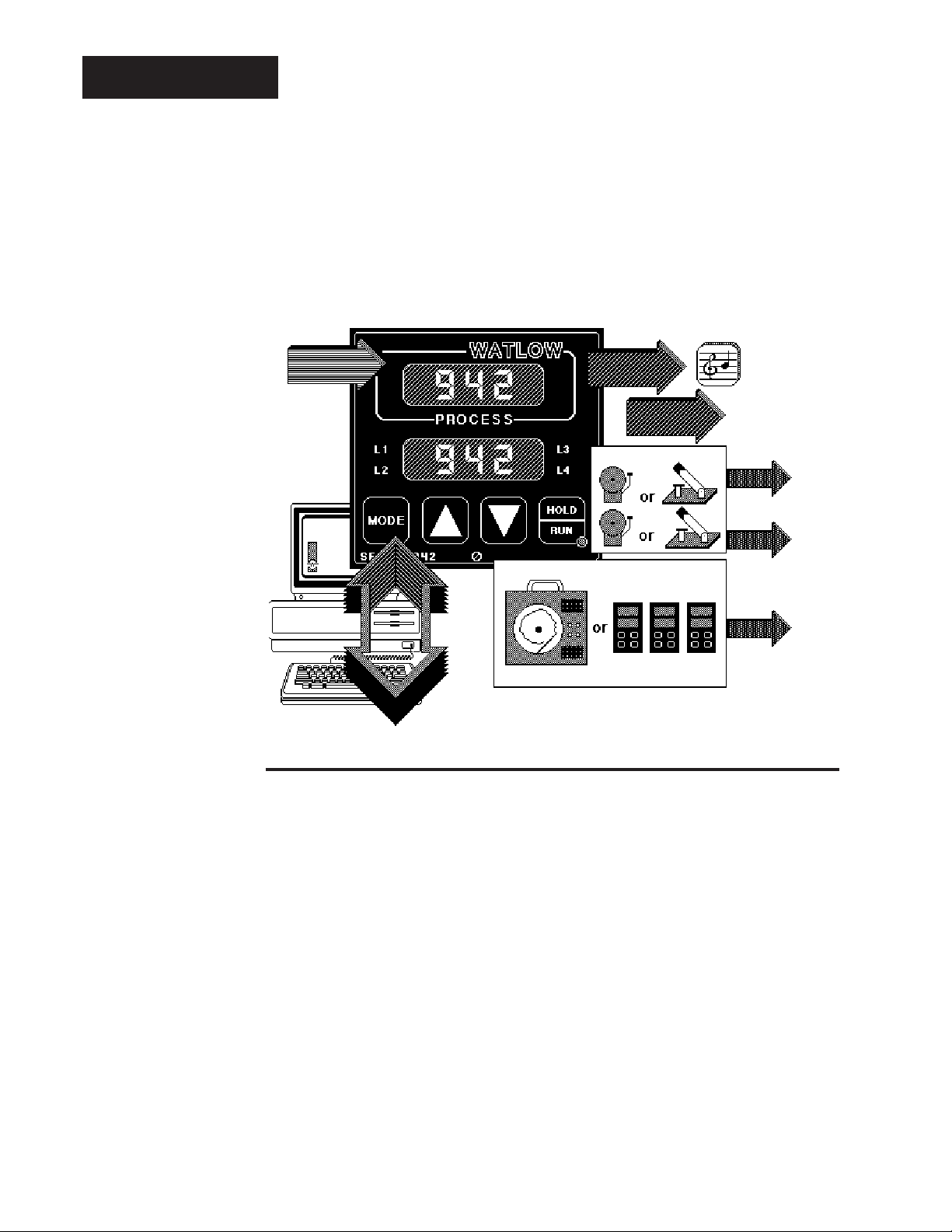
Figure 1 Series 942 Input and
Output Overview.
Single Input Type J, K, T, N, R, S, B, C or Pt2
Thermocouple, RTD or Process
RS-422A, RS423A
(RS-232C compatible), or EIA-485
Optional Computer
Interface
Dual Outputs-
PID or ON/OFF, User Selectable
Output 1
Heat or Cool
Output 1
Auto-tuning
(Heat only)
Output 2
Heat, Cool or None
Dual Alarms/Events
Retransmit Output
(Up to 10 Slaves)
Process Set Point
General Description
Welcome to the Watlow Series 942, a 1/4 DIN microprocessor-based ramping
temperature control. It is a single input, dual output, auto-tuning control with 24
step program capability and easy fixed set point operation. The 942 accepts a
Type J, K, T, N, R, S, B, C or Platinel 2 thermocouple, RTD, or process input. The
primary output is heating or cooling, while the secondary output can be heating,
cooling or none.
With the Series 942 you can select either PID or ON/OFF for Output 1 or 2. You
can input a complete set of PID parameters for both outputs, including proportional
band, reset/integral and rate/derivative. You can also select automatic tuning for
Output 1 while in the heating mode. By setting either output's proportional band to
zero, the Series 942 becomes a simple ON/OFF control with the switching differential selectable under the HYS Setup parameter.
Two optional auxiliary outputs may be alarms or events. An event is an ON/OFF
mechanical relay output. Events are based on time, and can trigger peripheral
equipment or processes. An optional retransmit output is offered in lieu of one of
the auxiliary outputs. Select either retransmit of process variable or set point.
Operator-friendly features include automatic LED indicators to aid in monitoring and
setup, as well as a calibration offset at the front panel. The Watlow Series 942
automatically stores all information in a non-volatile memory.
4
WATLOW Series 942 User's Manual
Getting Started, Chapter 1
Page 5
How to Open the 942
Before going further, open the Series 942 and pull the control chassis from its case.
Here's how:
The control chassis fastens to the case with a single standard screw located on the
!
LOCK
Three strip connector plugs, in the rear of the control chassis, feed power and
signals through the back of the case to the terminal strips. These plugs will let go
as you pull.
Starting Out
Starting Out
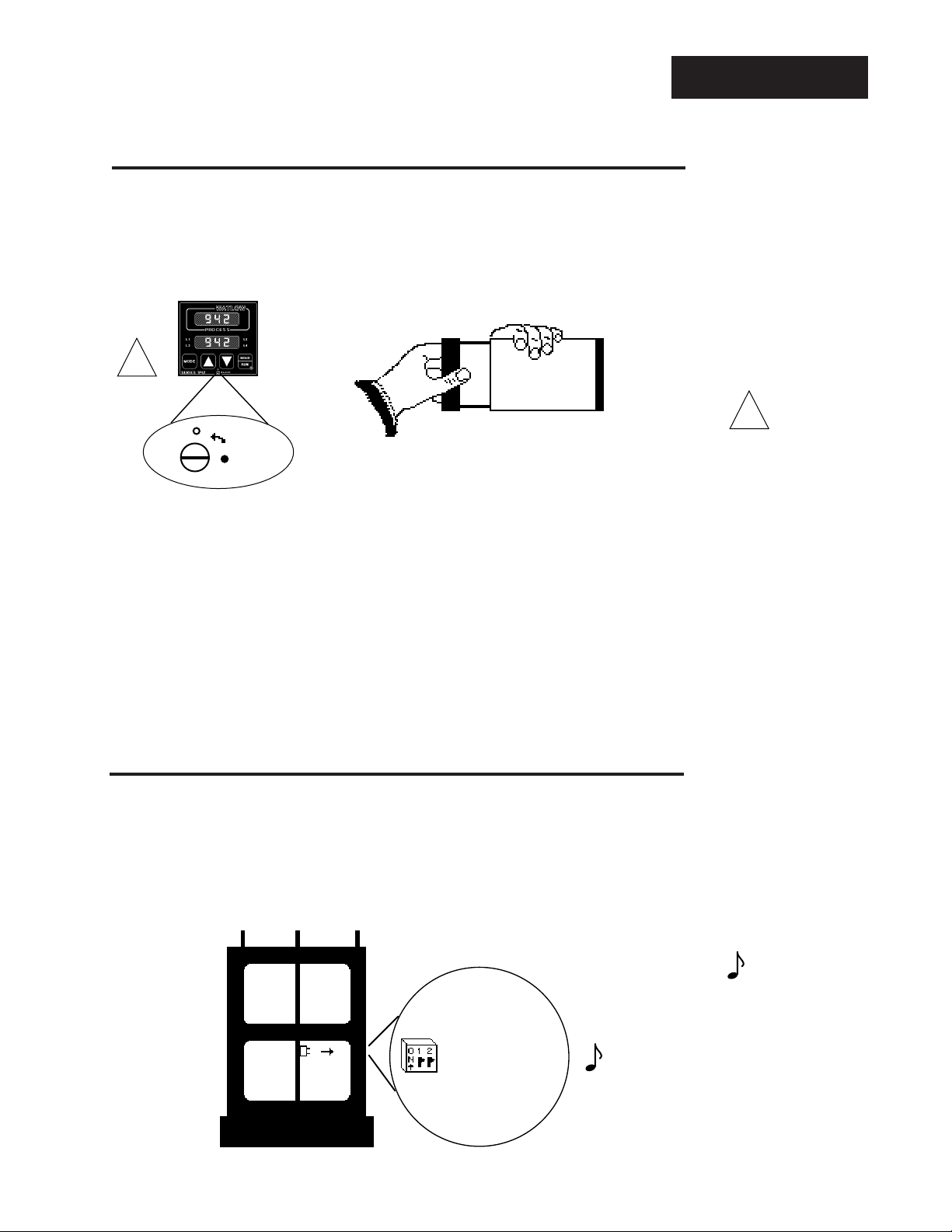
Figure 2 How to Open the
Series 942.
!
WARNING:
The front panel
screw turns 90
only. Do not apply
excessive force or
turn the screw more
than 90°.
°
When removing the Series 942 control from its case, pull firmly but gently. When
returning the control to the case, be sure you have the top up to match the plugs
with the case. The 942 will not fit in the case upside down, but check to be sure it
is oriented correctly. Press the unit in firmly, then turn the front panel screw
clockwise to secure it. This insures proper electrical contact.
How to Set the DIP Switches
The Watlow Series 942 has a Dual In-line Package (DIP) switch inside the control
on the A007-1954 circuit board (middle board). The location of the board and
switch appear below. The switches are clearly numbered. When Switch #1 is ON,
the Setup parameters can be viewed but not changed. When Switch #2 is ON, it
provides battery backup of the Run parameters. When the control leaves the
factory, both switches are OFF.
1 Hardware lockout of
Hardware Lockout of
1
Setup parameters
SETUP Parameters
2
2 Battery backup of the
Battery Discharge for
Storage
Run parameters
(Factory default is OFF)
Control Chassis - Top View
Figure 3 DIP Switch Location
and Orientation.
NOTE:
The lithium battery
has a life of approximately ten years.
When the battery
expires, Pout and
Run are affected
(see Chapters 4 & 5).
Return the unit to
the factory for a
replacement.
Getting Started, Chapter 1
WATLOW Series 942 User's Manual
5
Page 6

Installation
Chapter 2
How to Install and Wire the Series 942
System Planning
This chapter tells you how to install the Series 942. All mounting and wiring
information is right here. Because Watlow controls are thoroughly tested and
"burned in" before leaving the factory, the Series 942 is ready to install when you
receive it.
But before you begin working, read through this chapter to gain an understanding
of the entire installation. Consider sensor installation carefully. For detailed
information you'll need to look at the noise reduction guidelines in the Appendix of
this manual before making your panel cutout.
Installation Information
NOTE:
Removing the Series
942 chassis from its
case may make
mounting easier.
!
WARNING:
The front panel
screw turns 90°
only. Do not apply
excessive force or
turn the screw more
than 90°.
The Series 942 mounts in a panel cutout with two brackets, shipped with your
control. These brackets hold the case against the front panel. The Series 942
behind-panel dimensions are 3.6" (90 mm) high by 3.6" (90 mm) wide by 6" (152
mm) deep. Figure 5 on the next page shows the dimensions of the front panel
bezel. The 942 weighs 2.75 lbs. (1.25 kg) max.
For dimensional and mounting information, including the location of mounting
brackets and size of the front panel cutout, see Figures 5 through 7 on the next
page. Your panel's thickness can be from 0.06" (1.5 mm) to 0.25" (6.3 mm).
Installation Procedure
Follow this procedure to mount the Watlow Series 942 Temperature Control:
1. Make a panel cutout per the dimensions in Figure 6.
2. Remove the 942 from its case by turning the front panel screw 90° counterclockwise (CCW). Grip the bezel firmly and pull the control chassis out of the
case.
!
3. Place the case in the cutout you just made.
4. Attach the mounting brackets either to the top and bottom, or to both sides of
the unit.
5. Tighten the mounting brackets securely against your panel.
6
WATLOW Series 942 User's Manual
6. Insert the control chassis into its case and press the bezel to seat it. Turn the
front panel screw 90° clockwise (CW) to lock the control in place. The hardware installation is complete. Proceed to the wiring section from here.
Install and Wire, Chapter 2
Page 7
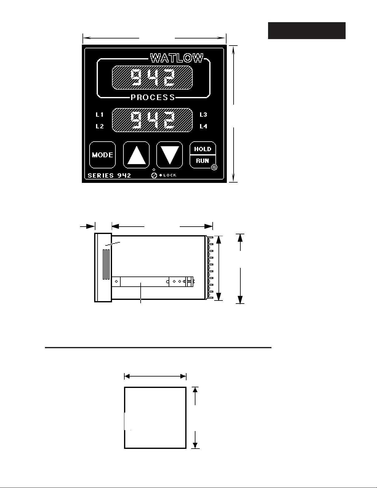
3.81" sq.
m
(97 mm)
Dimensions
3.81" sq.
(97 mm)
Figure 4 Series 942
Dimensions.
0.92"
(23 mm)
Your Panel
Your Panel
Thickness
Thickness:
0.06" to 0.25"
0.06 to 0.25
(1.52 to 6.35mm)
(1.524 to 6.35mm)
6.0"
(152 mm)
Bezel
Mounting Bracket
3.622 to 3.653
3.62" to 3.65"
(92.00 to 92.79mm)
(92 to 93 mm)
Panel
Cutout
3.63" X 3.63"
3.625 x 3.625
(92.08 X 92.08 mm)
(92.08 x 92.08mm)
Nominal
(90 mm ± 0.381)
3.62" to 3.65"
(92 to 93 mm)
(97 mm)
3.6" ± 0.015"
3.622 to 3.653
(92.00 to 92.79m
3.8"
Figure 5 Series 942
Panel Cutout
Dimensions.
Install and Wire, Chapter 2
NOTE:
k
All dimensions in inches.
WATLOW Series 942 User's Manual
7
Page 8
Power Wiring
NOTE:
For 50 or 60Hz
operation, no
adjustment or
jumper placement
is necessary.
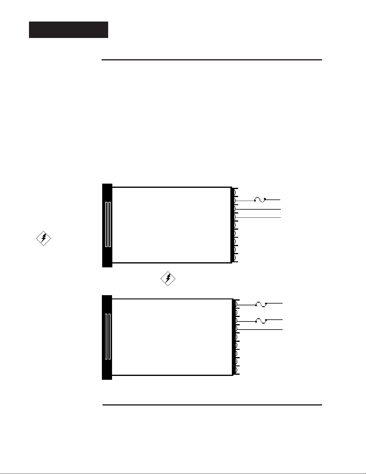
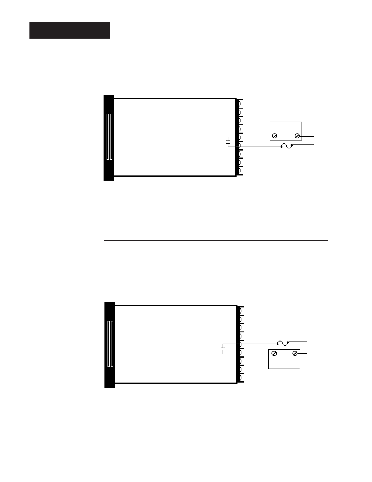
Figure 6 120 VAC Power
Wiring.
How to Wire the Series 942
The Series 942 wiring is illustrated by model number option. Check the terminal
designation sticker on the control and compare your model number to those
shown here and to the model number breakdown in the Appendix of this manual.
Series 942 internal circuits appear "inside" the line drawing of the 942, while
connections and terminal designations appear "outside" the line drawing. All
outputs are referenced to a de-energized state. The final wiring figure is a typical
system example.
When you apply power without sensor inputs on the terminal strip, the Series 942
displays "- - - -" in the Upper display, and Er7 in the Lower display. This error
indicates an open sensor or A/D error. Remove power to the control and connect
the sensor properly, see Page 10. All wiring and fusing must conform to the
National Electric Code and to any locally applicable codes as well.
Fuse
11
12
13
120 VAC
L1
L2
Earth Ground
CAUTION:
To avoid potential
electric shock, use
National Electric
Code (NEC) safety
practices when
wiring and connecting this unit to a
power source and to
electrical sensors or
peripheral devices.
Figure 7 240 VAC Power
Wiring.
Fuse
10
Fuse
12
13
240 VAC
L1
L2
Earth Ground
Sensor Installation Guidelines
We suggest you mount the sensor at a location in your process or system where it
reads an average temperature. Put the sensor as near as possible to the material
or space you want to control. The sensor should be thermally insulated from the
sensor mounting.
WATLOW Series 942 User's Manual
8
Install and Wire, Chapter 2
Page 9
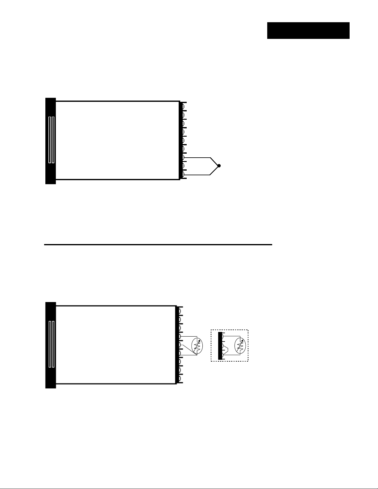
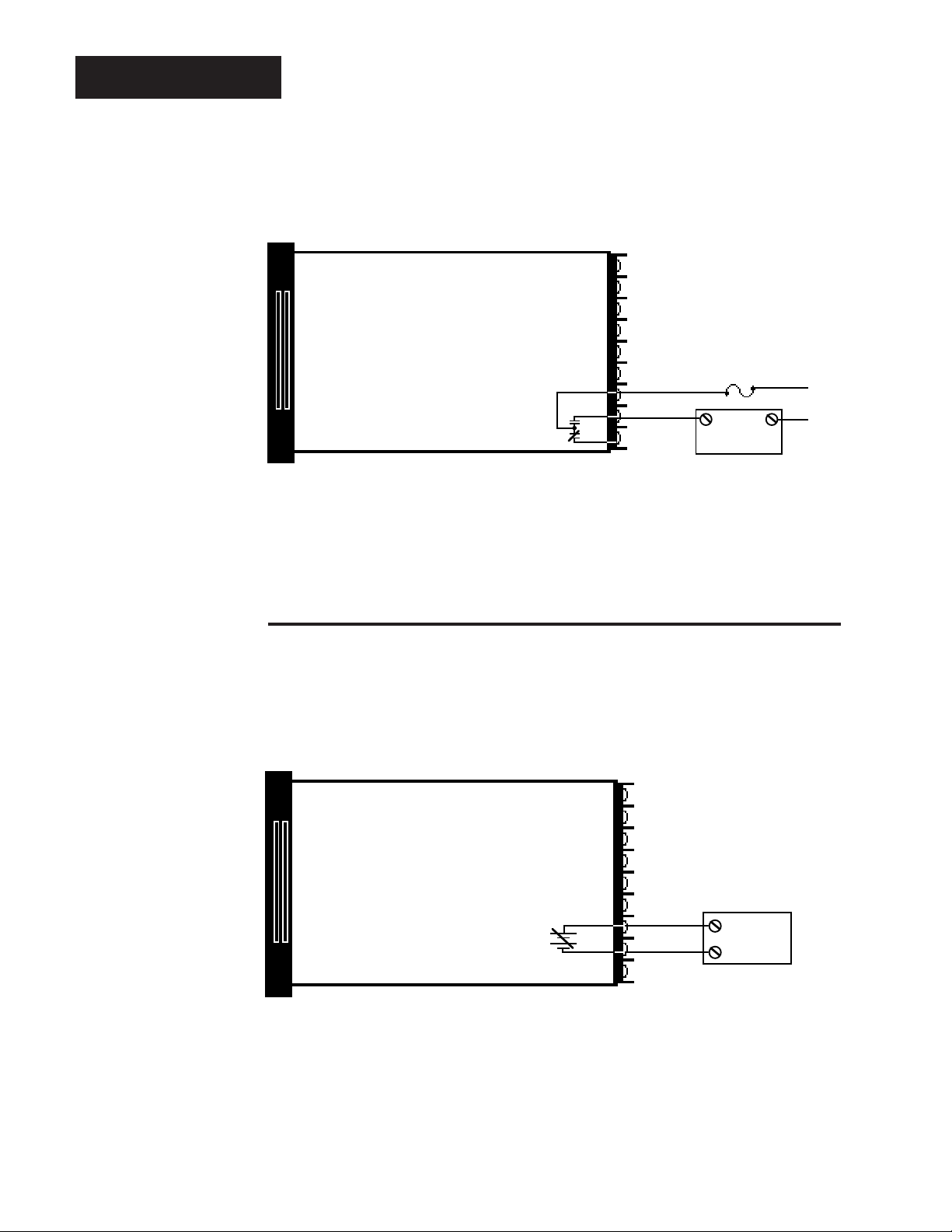
Thermocouple Input
Input Wiring
Model # 942A -
942A -
You must use an isolated or ungrounded thermocouple, if an external device with a nonisolated circuit common is connected to the 4-20mA or 0 - 5VDC output.
Extension wire for thermocouples must be of the same alloy as the thermocouple itself to
limit errors.
1 _ _ _ - _ 000 942A - 3 _ _ _ - _ 000
2 _ _ _ - _ 000 942A - 4 _ _ _ - _ 000
+
7
9
-
Figure 8 Thermocouple
Input Wiring.
RTD, 2 or 3 Wire
Model # 942A -
Long lead lengths create electrical resistance. There will be approximately +2°C input error
for every 1Ω of lead length resistance, when using a two wire RTD. The resistance, when
added to the resistance of the RTD element, will result in erroneous input to the instrument.
To overcome this problem, use a three wire RTD sensor, which compensates for lead length
resistance. When extension wire is used for a three wire RTD, all three extension wires
must have the same electrical resistance. (i.e. same gauge, copper stranded).
2 _ _ _ - _ 000 942A - 3 _ _ _ - _ 000
Jumper #5 to #6
for 2-Wire RTD
4
5
6
4
5
6
Figure 9 2 or 3 wire RTD
Input Wiring.
Install and Wire, Chapter 2 WATLOW Series 942 User's Manual
9
Page 10
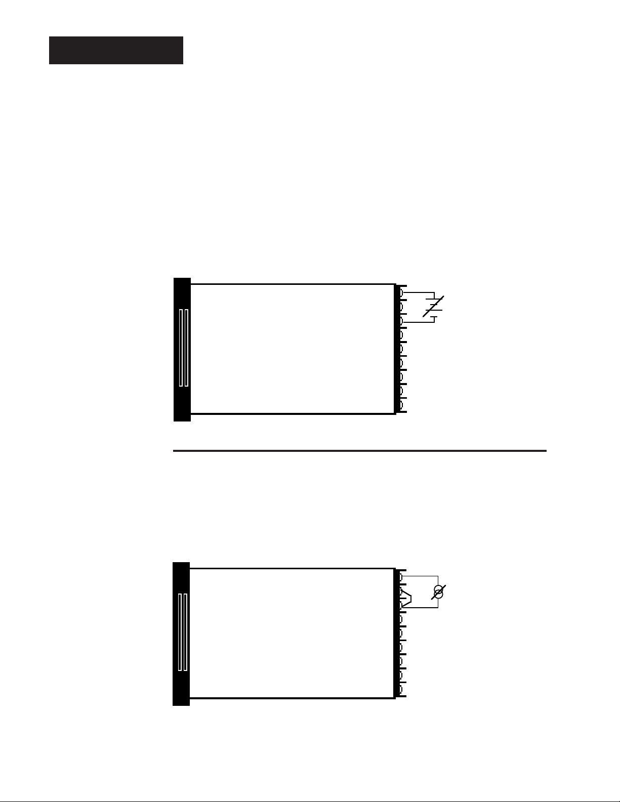
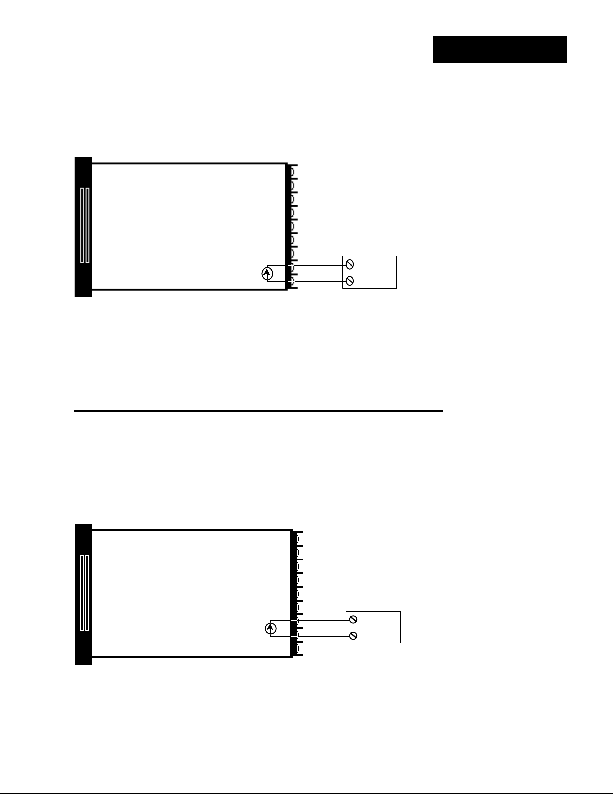
Input Wiring
Figure 10 0 - 5VDC Process
Input Wiring.
When using a process input such as 0 - 5VDC or 4 - 20mA, the rL and rH settings scale the
display to match the measured range of the process signal.
An example of this is: A pressure transducer operates over a range of 0 - 300 PSI, delivering
a 4 - 20mA output signal for this range. By setting rL = 0 and rH = 300, the Series 942 now
displays a direct reading of pressure.
0 - 5VDC Process Input
Model # 942A - 2 _ _ _ - _ 000 942A - 3 _ _ _ - _ 000
+
1
V
2
3
-
DC
NOTE:
When using a
0 - 5VDC process
input, the input
impedance is
100KΩ.
Figure 11 4 - 20mA Process
Input Wiring.
4 - 20mA Process Input
Model # 942A - 2 _ _ _ - _ 000 942A - 3 _ _ _ - _ 000
A jumper must be
installed between
Terminals #2 and 3.
1
2
3
+
DC
I
-
NOTE:
When using a
4 - 20mA process
input, the input
impedance is 249Ω.
WATLOW Series 942 User's Manual
10
Install and Wire, Chapter 2
Page 11
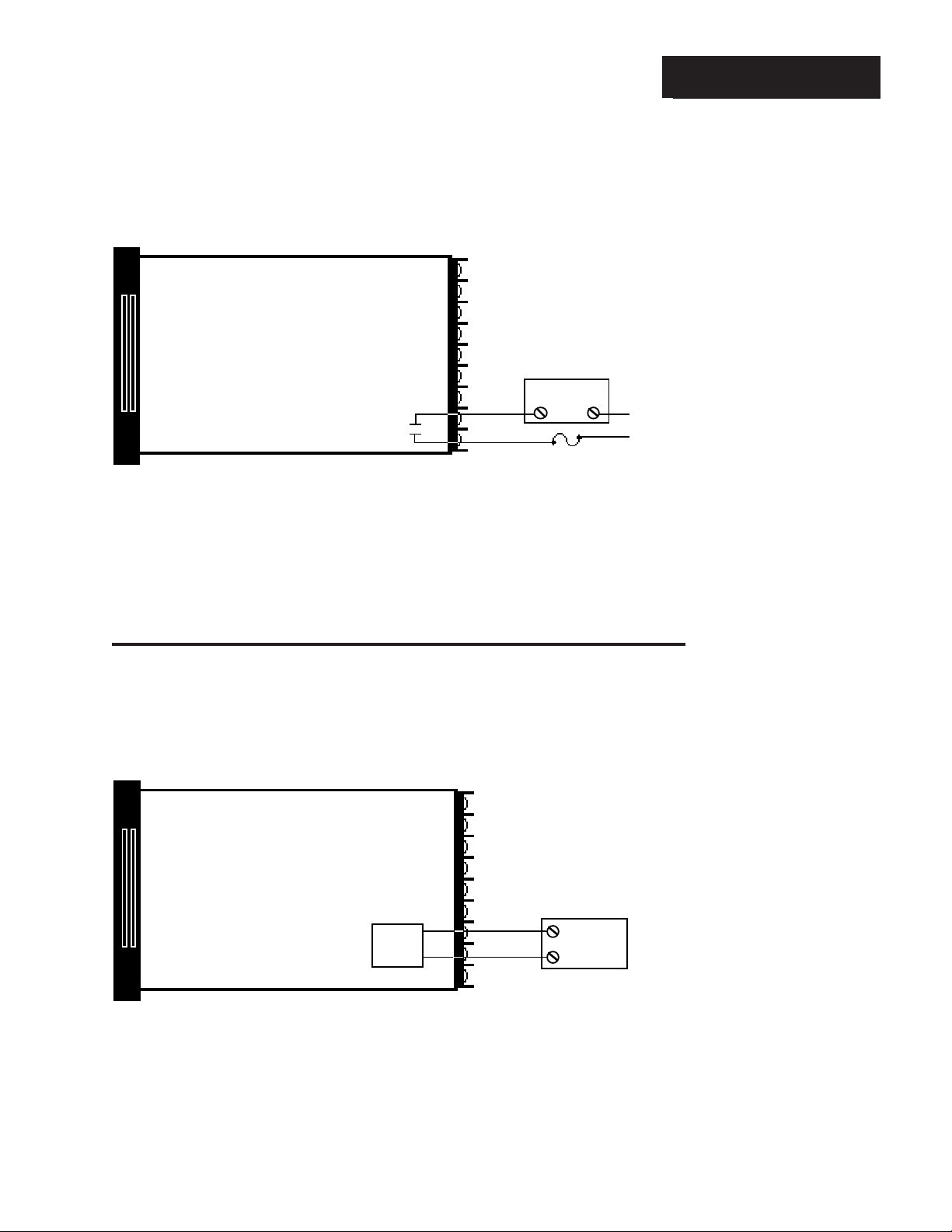
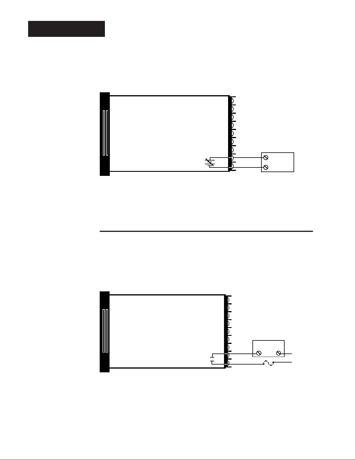
Solid State Relay With Contact Suppression, Output 1
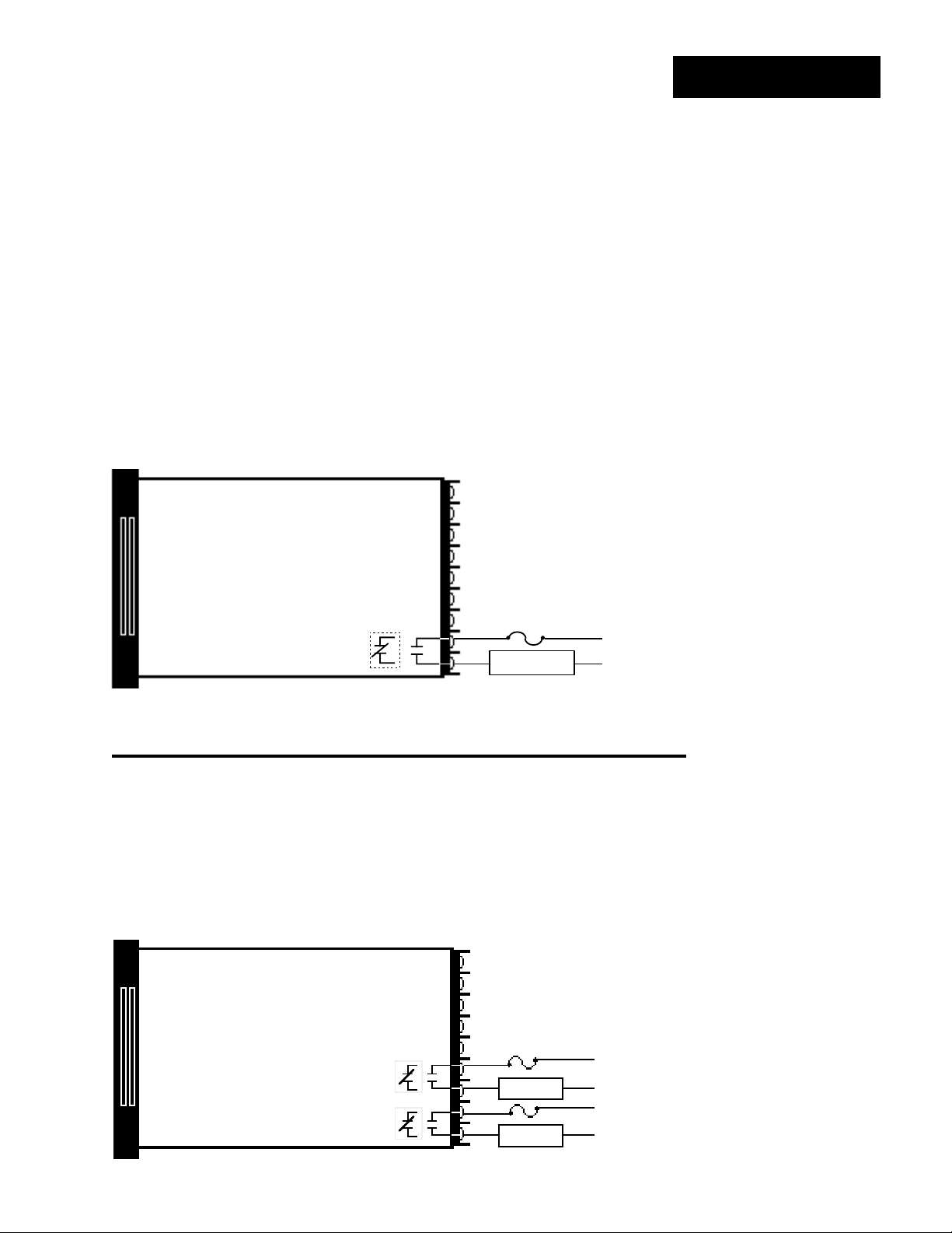
Model # 942A - _ B _ _ - _ 000
Solid State Relay, Form A, 0.5 Amp
External
N.O.
17
COM.
18
Solid State Relay With Contact Suppression
Watlow's solid state relay changes state at zero volts, which is "zero-cross switching." They
are also optically isolated, which means the output circuitry is energized by infrared light
striking a photosensitive device. This results in a virtual absence of electrically generated
noise, and provides electrical isolation between the input and output. For use in switching
mercury relays or small AC loads. Off state impedance is 20KΩ minimum.
Load
Fuse
L2
L1
Output 1 Wiring
Figure 12 Solid State Relay
With Contact
Suppression,
Output 1 Wiring.
NOTE:
This output is supplied with an arc
suppression snubber across the output terminals. High
impedance loads
may remain energized even though
the output device is
turned OFF.
Switched DC Output (Open Collector), Output 1
Model # 942A - _ C _ _ - _ 000
Switched DC, Open Collector, Non-Isolated
16
17
External
+
Load
Logic
Switch
Switched DC
Watlow's solid state switch is a low current DC output (open collector) used to switch an
external power switching device such as an SSR or an electromechanical relay. The input
specifications of the power switching device must match those listed for the SS switch
output. The power switching device must provide isolation between the SS switch output
and load power since the SS switch output is a non-isolated output. Minimum load resistance is 500Ω. Available current is 22mA maximum. Typical voltage drop across a 1KΩ
load is 12 to 19 volts.
-
+
Figure 13 Switched DC
(Open Collector),
Output 1 Wiring.
Install and Wire, Chapter 2 WATLOW Series 942 User's Manual
11
Page 12
Output 1 Wiring
Figure 14 6 Amp Mechanical
Relay, Output 1
Wiring.
NOTE:
This output is supplied with an arc
suppression snubber across the output terminals. High
impedance loads
may remain energized even though
the output device is
turned OFF.
Mechanical Relay, 6 Amp, Form C, Output 1
Model # 942A - _ D _ _ - _ 000
Mechanical Relay, Form C, 6 Amp
COM.
16
N.O.
17
18
N.C.
Mechanical Relay
The electromechanical relay is an electrical and mechanical device with moving parts.
When power is applied to the relay solenoid, contact closure is created through movement
of the "common" contact of the relay.
Off state impedance is 20KΩ minimum.
Fuse
External
Load
L1
L2
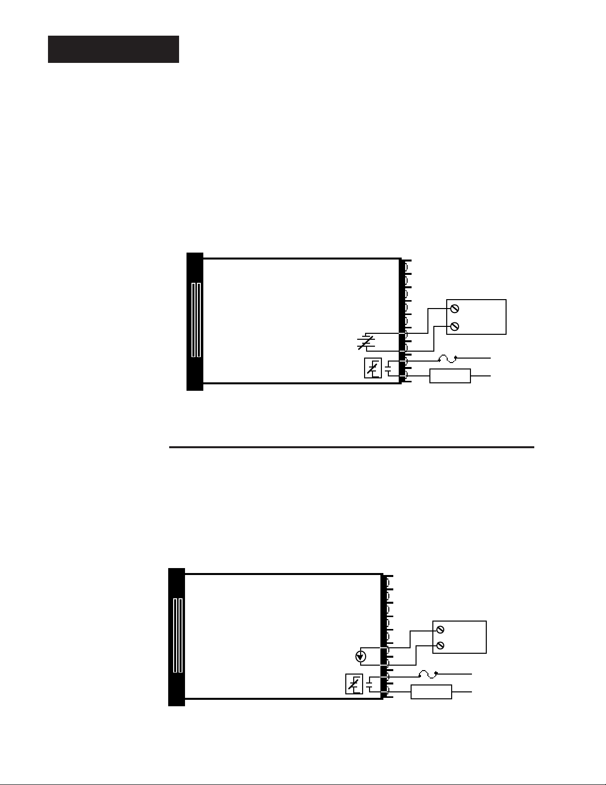
Figure 15 Process, 0 - 10VDC,
Output 1 Wiring.
Process, 0 - 10VDC, Output 1
Model # 942A - _ E _ _ - _ 000
Process, 0-10VDC, Non-Isolated
16
17
-
+
External
Load
-
+
Process Output
Proportional value determined by the control to balance the sensor input and set point. This
value will fall between 0 - 10VDC depending on the thermal characteristics of the system.
Load impedance is 10KΩ minimum.
WATLOW Series 942 User's Manual
12
Install and Wire, Chapter 2
Page 13
Process, 4 - 20mA, Output 1
Output 1 Wiring
Model # 942A - _
Process, 4-20 mA, Non-Isolated
Process Output
Proportional value determined by the control to balance the sensor input and set point. This
value will fall between 4 - 20mA depending on the thermal characteristics of the system.
Load impedance is 600
F _ _ - _ 000
Ω maximum.
+
I
DC
-
17
18
+
External
-
Load
Figure 16 Process, 4 - 20mA,
Output 1 Wiring.
Process, 0 - 20mA, Output 1
Model # 942A - _
Process, 0-20 mA, Non-Isolated
Process Output
Proportional value determined by the control to balance the sensor input and set point. This
value will fall between 0 - 20mA depending on the thermal characteristics of the system.
Load impedance is 600
G _ _ - _ 000
Ω maximum.
-
I
DC
+
16
17
External
+
Load
Figure 17 Process, 0 - 20mA,
Output 1 Wiring.
Install and Wire, Chapter 2 WATLOW Series 942 User's Manual
13
Page 14
Output 1 Wiring
Figure 18 Process, 0 - 5VDC,
Output 1 Wiring.
Process, 0 - 5VDC, Output 1
Model # 942A - _ H _ _ - _ 000
Process, 0-5VDC, Non-Isolated
17
++
-
Process Output
Proportional value determined by the control to balance the sensor input and set point. This
value will fall between 0 - 5VDC depending on the thermal characteristics of the system.
Load impedance is 10KΩ minimum.
18
External
-
Load
Figure 19 Solid State Relay
Without Contact
Suppression, Output
1 Wiring.
Solid State Relay Without Contact Suppression, Output 1
Model # 942A - _ K _ _ - _ 000
Solid State Relay, Form A, 0.5 Amp
External
N.O.
17
COM.
18
Solid State Relay Without Contact Suppression
Watlow's solid state relay changes state at zero volts, which is "zero-cross switching." They
are also optically isolated, which means the output circuitry is energized by infrared light
striking a photosensitive device. This results in a virtual absence of electrically generated
noise, plus output to input electrical isolation. Off state impedance is nearly infinite and
should be used to switch high impedance non-inductive loads.
Load
Fuse
L2
L1
WATLOW Series 942 User's Manual
14
Install and Wire, Chapter 2
Page 15
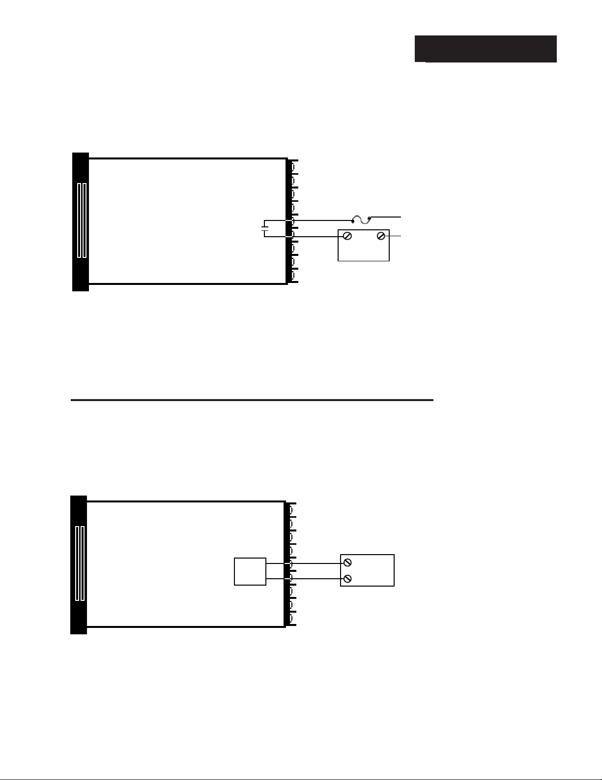
Solid State Relay With Contact Suppression, Output 2
Model # 942A - _ _ B _ - _ 000
Solid State Relay, Form A, 0.5 Amp
N.O.
14
15
COM.
Solid State Relay With Contact Suppression
Watlow's solid state relay changes state at zero volts, which is "zero-cross switching." They
are also optically isolated, which means the output circuitry is energized by infrared light
striking a photosensitive device. This results in a virtual absence of electrically generated
noise, and provides electrical isolation between the input and output. For use in switching
mercury relays or small AC loads. Off state impedance is 20K
Ω minimum.
Fuse
External
Load
L1
L2
L2
L1
Output 2 Wiring
Figure 20 Solid State Relay
With Contact
Suppression,
Output 2 Wiring.
NOTE:
This output is supplied with an arc
suppression snubber across the output terminals. High
impedance loads
may remain energized even though
the output device is
turned OFF.
Switched DC Output (Open Collector), Output 2
Model # 942A - _ _ C _ - _ 000
Switched DC, Open Collector, Non-Isolated
+
Logic
Switch
Switched DC
Watlow's solid state switch is a low current DC output (open collector) used to switch an
external power switching device such as a SSR or an electromechanical relay. The input
specifications of the power switching device must match those listed for the S.S. switch
output. The power switching device must provide isolation between the S.S. switch output
and load power since the S.S. switch output is a non-isolated output. Minimum load
resistance is 500Ω. Available current is 9mA minimum and 22mA maximum.
-
14
15
+
External
-
Load
Figure 21 Switched DC Output
(Open Collector),
Output 2 Wiring.
Install and Wire, Chapter 2 WATLOW Series 942 User's Manual
15
Page 16
Output 2 Wiring
Figure 22 6 Amp Mechanical
Relay, Output 2
Wiring.
Mechanical Relay, 6 Amp, Form A, Output 2
Model # 942A - _ _ D _ - _ 000
Mechanical Relay, Form A, 6 Amp
14
15
N.O.
COM.
External
Load
Fuse
L2
L1
L1
L2
NOTE:
This output is supplied with an arc
suppression snubber across the output terminals. High
impedance loads
may remain energized even though
the output device is
turned OFF.
Figure 23 Solid State Relay
Without Contact
Suppression,
Output 2 Wiring.
Mechanical Relay
The electromechanical relay is an electrical and mechanical device with moving parts.
When power is applied to the relay solenoid, contact closure is created through movement
of the "common" contact of the relay. Off state impedance is 20K
Ω minimum.
Solid State Relay Without Contact Suppression, Output 2
Model # 942A - _ _ K _ - _ 000
Solid State Relay, Form A, 0.5 Amp
14
15
N.O.
COM.
Fuse
External
Load
L1
L2
L1
L2
WATLOW Series 942 User's Manual
16
Solid State Relay Without Contact Suppression
Watlow's solid state relays change state at zero volts, which is "zero-cross switching." They
are also optically isolated, which means the output circuitry is energized by infrared light
striking a photosensitive device. This results in virtual absence of electrically generated
noise, while providing output to input electrical isolation. Off state impedance is nearly
infinite and should be used to switch high impedance non-inductive loads.
Install and Wire, Chapter 2
Page 17
For more information on alarms, alarm jumper selection and events,
see Chapter 6.
Mechanical Relay
The electromechanical relay is an electrical and mechanical device with moving parts.
When power is applied to the relay solenoid, contact closure is created through movement of
the "common" contact of the relay. Off state impedance is 20K
Ω minimum.
Mechanical Relay, 6 Amp, Single Form A or B, Auxiliary Output
Model # 942A- _ _ _ 1 - _ 000
Auxiliary Wiring
Figure 24 Auxiliary Option 1
Wiring.
Mechanical Relay, Form A or B, 6 Amp
Output #3
26
27
Load
L1
L2
Mechanical Relay, 6 Amp, Dual Form A or B, Auxiliary Output
Model # 942A- _ _ _ 2 - _ 000
Mechanical Relay, Form A or B, 6 Amp
Fuse
Output #4
Output #3
24
25
26
27
Load
Fuse
Load
L1
L2
L1
L2
NOTE:
This output is supplied with an arc
suppression snubber across the output terminals. High
impedance loads
may remain energized even though
the output device is
turned OFF.
Figure 25 Auxiliary Option 2
Wiring.
Install and Wire, Chapter 2 WATLOW Series 942 User's Manual
17
Page 18
Auxiliary Wiring
Mechanical Relay
The electromechanical relay is an electrical and mechanical device with moving parts.
When power is applied to the relay solenoid, contact closure is created through movement of
the "common" contact of the relay.
Mechanical Relay, 6 Amp, Form A or B/0 - 5VDC Retransmit
Model # 942A- _ _ _ 3 - _ 000
Figure 26 Auxiliary Option 3
Wiring.
NOTE:
This output is supplied with an arc
suppression snubber across the output terminals. High
impedance loads
may remain energized even though
the output device is
turned OFF.
Process, 0-5VDC, Non-Isolated
24
25
26
27
+
Fuse
Load
External
Load
Mechanical Relay, Form A or B, 6 Amp
Output #4
Output #3
Load impedance 10K
Ω mimimum.
-
+
Mechanical Relay, 6 Amp, Form A or B/4 - 20mA Retransmit
Model # 942A- _ _ _ 4 - _ 000
L1
L2
Figure 27 Auxiliary Option 4
Wiring.
WATLOW Series 942 User's Manual
18
Process, 4-20 mA, Non-Isolated
Mechanical Relay, Form A or B, 6 Amp
Output #4
Output #3
Load impedance 600Ω maximum.
I
DC
+
External
-
-
+
24
25
26
27
Fuse
Load
Load
L1
L2
Install and Wire, Chapter 2
Page 19
Retransmit Output
When using a retransmit output such as 0 - 5VDC or 4 - 20mA, the rL and rH settings scale
the range of the retransmit output.
An example of this is: By setting rL = 0, rH = 1000 and Ot4 = PrOC a process value of 500
will result in a retransmitted signal of 2.5VDC or 12mA.
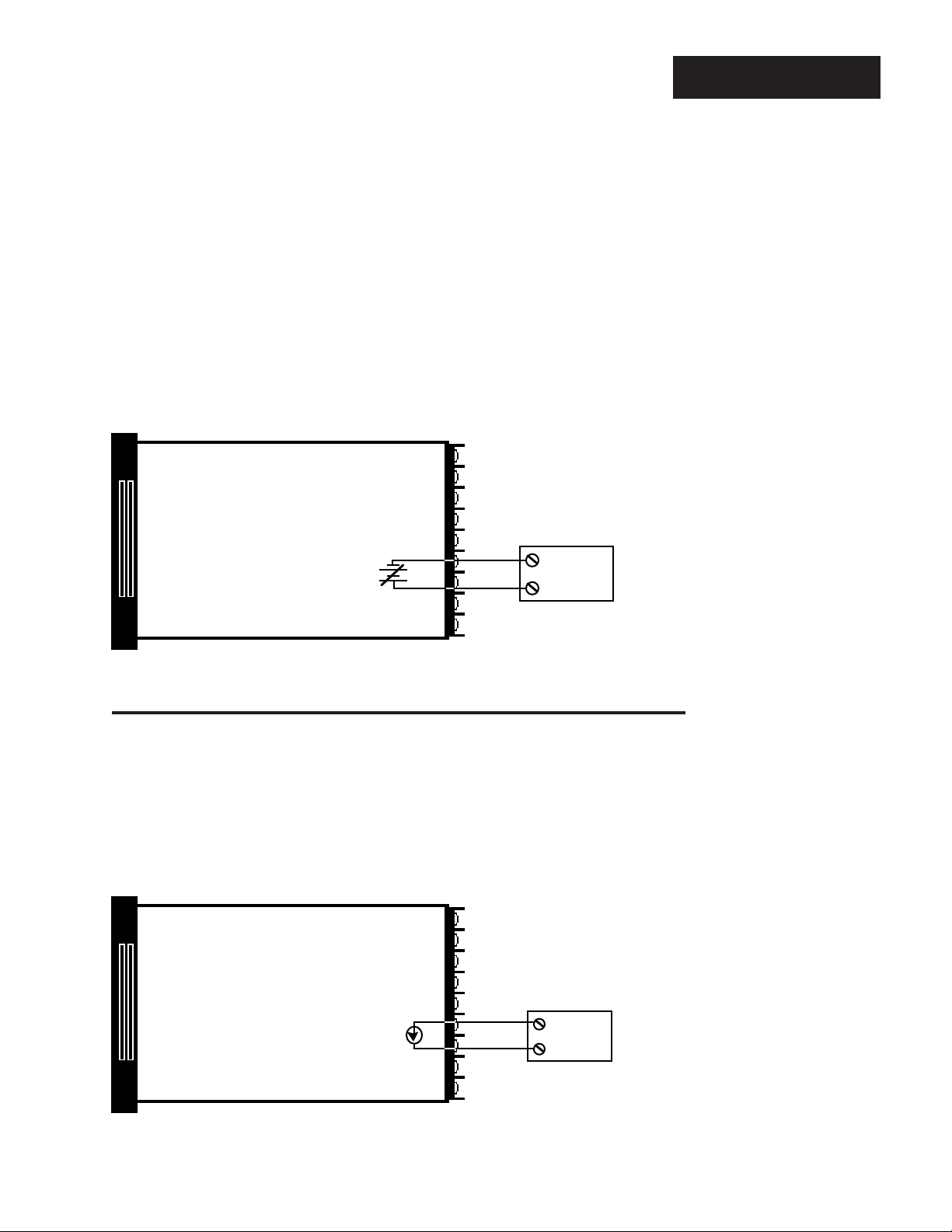
0 - 5VDC Retransmit, Auxiliary Output
Model # 942A- _ _ _ 5 - _ 000
Process, 0-5VDC non-isolated
Auxiliary Wiring
Figure 28 Auxiliary Option 5
Wiring.
-
+
Load impedance 10KΩ mimimum.
4 - 20mA Retransmit, Auxiliary Output
Model # 942A- _ _ _ 6 - _ 000
Process, 4-20 mA, Non-Isolated
24
25
External
+
Load
Figure 29 Auxiliary Option 6
Wiring.
-
IDC
+
Load impedance 600
Install and Wire, Chapter 2 WATLOW Series 942 User's Manual
Ω maximum
24
25
+
-
External
Load
19
Page 20

n
Wiring Example
Figure 30 System Wiring
Example
CAUTION:
All wiring and fusing must conform to the National Electric Code NFPA70. Contact your local board for additional information. Failure to observe NEC safety
guidelines could result in injury to personnel.
!
WARNING:
Watlow mercury relays are designed to be used only with resistive loads.
945A-2DD0-A000
942A-1DD0-A000
Temperature Control
Temperature Control
Type "J"
Thermocouple
L1
Fuse
Load
Power
L2
(+)
(-)Red
7
9
Mercury
Relay for
Control
14
15
16
17
11
12
13
Fuse
Indicator ON
when limit trips
Fuse
L1
ControlPower
L2
120 VAC
Earth Ground
L1
L2
L1
L2
Terminal Functio
High Limit
Control Power
120 VAC
945A-2DD0-A000
942A-1DD0-A000
1 Not Used
2 Not Used
3 Not Used
4 Not Used
5 Not Used
6 Not Used
7 T.C. +
8 Not Used
9 T.C. 10 L1 240V
11 L1 120V
12 L2
13 Earth Ground
14 N.O.
15 Com.
16 Com.
17 N.O.
18 N.C.
Integral Setpot
Output #2
Output #1
Heat
Load
T/C T/C
Process Sensor
WATLOW Series 942 User's Manual
20
π
Coil
!
High Limit
Mechanical
Contactor
Indicator ON when
limit trips
L2
Limit Sensor
Normally Open
Momentary Switch
140A-16XX-6000
High Limit Control
(-)
(+)TC Input
Install and Wire, Chapter 2
Page 21

Chapter 3
How to Use the Keys and Displays
After 1 minute with no key activations, the control reverts to the process
value in the Upper display and the set point in the Lower display, except
when in the RUN menu.
Upper Display
Red, 0.56" (14 mm) high, seven segment, four digit LED display, indicating
process variable (such as actual temperature) in addition to parameter values,
or an open sensor. When powering up, the Process display will be blank for 8
seconds.
Keys/Displays
Figure 31 Series 942
Keys and Displays.
L 1 & L2
When lit, these LED's tell
you when Output 1 or 2 is
energized. L2 only appears
if your unit has a #2 output.
Lower Display
Red 0.56" (14 mm) high, seven segment, four digit LED display, indicating the
set point, menu parameters, and alarm or error codes.
UP/DOWN Keys
When pressed simultaneously for 3 seconds, the Setup Menu appears
displaying the LOC parameter. At the LOC parameter, continue to press
the UP/DOWN keys, and the Calibration Menu will appear.
UP Key
Increases the value of the
displayed parameter. A light
touch increases the value by
one. Hold the key down to
increase the value at a rapid
rate. New data is self entering
in 5 seconds.
DOWN Key
Decreases the value of the
displayed parameter. A light
touch decreases the value by
one. Hold the key down to
decrease the value at a rapid
rate. New data is self entering
in 5 seconds.
HOLD/RUN Key
Pressed once, it clears
any latched alarms
without altering the
HOLD/RUN status. To
run or halt a program see
Chapter 5 for details.
L3 & L4
When lit, these LEDs
indicate an energized
alarm or event condition for Output 3 or 4.
Only appears on those
units with auxiliary
option.
MODE Key
Steps the control through the
Operating menu; also, automatically enters data changes before
proceeding to the next parameter.
Keys and Displays, Chapter 3
Front Panel
Locking Screw
Secures or releases the
control chassis from its case.
HOLD/RUN LED
Lit when the control is RUNning. When blinking, press the
HOLD/RUN key again to begin
RUNning.
WATLOW Series 942 User's Manual
21
Page 22

Setup
e
t
w
2
2
e
e
y
l
t
Figure 32 Entering the Setup
Menu.
Chapter 4
How To Setup The Series 942
Setting up the Series 942 is a simple process. First configure the 942's features to
your application in the Setup Menu, enter values in the Operating Menu, and program your control. Use the MODE key to move through the menus and the UP/
DOWN keys to select data. At this point, enter the Calibration menu, and select US
or SI under the dFL parameter if necessary. Rate, reset and °F appear with US,
and integral, derivative and °C appear with SI. See Appendix III.
Entering the Setup Menu
The Setup Menu displays the parameters that configure the Series 942's features
to your application. Enter the Setup Menu by pressing the UP/DOWN keys simultaneously for 3 seconds. The Lower display shows the LOC parameter, and the
Upper display shows its current level. All keys are inactive until you release both
keys. You can reach the LOC parameter from anywhere except the Run menu.
While in the Setup menu, all outputs are OFF.
Use the MODE key to cycle through the menu, and the UP/DOWN keys to select
Setup data. You will not see all parameters in this menu, depending on the unit's
configuration, model number, and LOC parameter. After stepping through the
menu it returns to the control set point parameter under the Operation menu.
Figure 33 The Setup Menu.
NOTE:
The rL and rH
parameters are used
to scale the display
for process inputs,
and/or will scale the
retransmit range for
process output. rL
and rH also limit the
ramge of the set
point.
[SP]
Loc
In
dEC
C_F
rL
rH
Ot1
HYS1
Ot2
HYS2
Ot3
AL1
LAt1
HYS3
SIL
( )
( )
( )
( )
( )
( )
( )
( )
( )
( )
( )
( )
( )
( )
( )
M
[Set Point]
User lock out
Input type
Decimal plac
Celcius_Fahrenhei
Range lo
Range high
Output 1
Hysteresis 1
Output 2
Hysteresis 2
Output 3
Alarm 1
Latching for alarm 1
Hysteresis 3
Silence alarm
= Parameter may or may not appear
depending on control configuration.
( )
Ot4
AL2
LAt2
HYS4
rtd
PtYP
gSd
Pout
PStr
bAUd
dAtA
Prot
Addr
LOg
Int
tAg
( )
( )
( )
( )
( )
( )
( )
( )
( )
( )
( )
( )
( )
( )
( )
Output 4
Alarm
Latching for alarm
Hysteresis 4
RTD calibration curv
Program type
Guaranteed soak deviation
Power outag
Profile star
Baud rate
Data bits and parit
Protocol type
Address
Logging printout
Time interva
Variables to transmit
22
WATLOW Series 942 User's Manual
Setup, Chapter 4
Page 23

Setup Parameters
When you are at the top of the menu, the Series 942 displays the user level of
operation in the Upper display, and the LOC parameter in the Lower display.
When you press the MODE key, the value of the next parameter appears in the
Upper display, and the parameter appears in the Lower display.
Setup
Lock: Selects the level of operator lockout.
Range: 0 - 3 Default: 0
LOC 0: All operating parameters may be viewed or changed.
LOC 1: Locks out the PID parameters. Set point, process value and events are the
only visible operating parameters, set point is adjustable in this level. A
profile can be viewed, changed, run or halted.
LOC 2: Locks out the PID parameters and the Program menu. Set point, process
value and events are the only visible operating parameters, set point is
adjustable. A profile can be run or halted but not viewed or changed.
LOC 3: Locks out the entire Operating and Program menus. Set point and process
value are the only visible operating parameters, set point is not adjustable.
A profile can be run or halted but not viewed or changed.
Input: Selects the sensor input type. Only those input types which are compatible
with your unit will appear. See the model number information for your type. Chang-
ing this parameter erases all profile steps and defaults them to an End step.
Range: J, K (appears as H), t, n, c, r, S, b, Pt2, rtd1, rtd.1, 0-5, 420 Default: J or r
Decimal: Selects the location of the decimal point for all process related data. This
parameter only appears if the In parameter is 0-5 or 420.
Range: 0, 0.0, 0.00 Default: 0
LOC
In
dEC
Celsius _ Fahrenheit: Selects the units of temperature measurement for the
control. This parameter only appears if In = T/C or RTD input. Changing this
parameter erases all profile steps and defaults them to an End step.
Range: C or F Default: F
Range Low: Selects the low end of the set point range. See the model number
and specification information in the Appendix, and Table 1 on Page 26 for sensor
range values. Also used to set the low end of the process input and/or the low end
of the range for the retransmit output. 0.0VDC and 4mA represent Range Low (rL)
for process inputs and outputs. Process inputs and outputs are linearly scaled
between rL and rH. Changing this parameter erases all profile steps and
defaults them to an End step.
Range: Sensor range low to rH Default: Low limit of sensor type
Range High: Selects the high end of the set point range. See the model number
and specification information in the Appendix, and Table 1 on Page 26 for your
sensor range values. Also used to set the high end of the process input and/or the
high end of the range for the retransmit output. 5.0VDC and 20mA represent Range
High (rH) for process inputs and outputs. Process inputs and outputs are linearly
scaled between rL and rH. Changing this parameter erases all profile steps and
defaults them to an End step.
Range: Sensor range high to rL Default: High limit of sensor type
Setup, Chapter 4 WATLOW Series 942 User's Manual
C _ F
rL
rH
23
Page 24

Setup
Ot1
HYS1
Ot2
HYS2
Ot3
Output 1: Selects the output action for the primary output. Action in response
to the difference between set point and process variable. Select ht (heat) for
reverse acting or select CL (cool) for direct acting.
Range: ht, CL Default: ht
Hysteresis 1: Selects the switching hysteresis for Output 1 when Pb1 = 0 (ON/
OFF). See Page 29 for the Pb1 parameter.
Range: 1°F - 999°F 0.1°F - 99.9°F Default: 3°F
1°C - 540°C 0.1°C - 54.0°C
1Unit - 999 Units 0.1 Units - 99.9 Units
Output 2: Selects the output action for the secondary output. Action in response to the difference between set point and process variable. Select ht
(heat) for reverse acting or select CL (cool) for direct acting. This parameter only
appears if you have a secondary output. If Ot1 = ht: Range: CL, no
If Ot1 = CL: Range: ht, no Default: CL
Hysteresis 2: Selects the switching hysteresis for Output 2 when 0 = (ON/OFF)
under the Pb 2 parameter. See Page 29 for the Pb2 parameter. This parameter
only appears if you have a secondary output.
Range: 1°F - 999°F 0.1°F - 99.9°F Default: 3°F
1°C - 540°C 0.1°C - 54.0°C
1Unit - 999 Units 0.1 Units - 99.9 Units
Output 3: Selects Output 3 as an alarm or an event. This parameter only
appears if you have at least one auxiliary output.
Range: AL, Ent, no Default: AL
AL1
LAt1
HYS3
SIL
Alarm 1: Determines whether the alarm type for Alarm 1 is process or deviation. A process alarm is set at an absolute temperature to prevent over/underrange. This parameter only appears if you ordered auxiliaries with your unit and
Ot3 = AL. See Chapter 6 for more information on alarms.
Range: Pr, dE Default: Pr
Latching 1: Selects whether Alarm 1 is latching or non-latching. Latching
alarms must be cleared before the alarm output will reset. Non-latching automatically resets the alarm output when the condition clears. This parameter
only appears if your unit has auxiliary outputs and Ot3 = AL. See Chapter 6.
Range: LAt or nLA Default: nLA
Hysteresis 3: Selects the switching hysteresis for Output 3 and appears if
Ot3 = AL, and your unit has an auxiliary output.
Range: 1°F - 999°F 0.1°F - 99.9°F Default: 3°F
1°C - 540°C 0.1°C - 54.0°C
1Unit - 999 Units 0.1 Units - 99.9 Units
SIL: Selects alarm silencing (inhibit) for Output 3. This parameter only appears
when AL1 = dE, and Ot3 = AL. For more information see Chapter 6.
Range: On or OFF Default: OFF
24
WATLOW Series 942 User's Manual
Setup, Chapter 4
Page 25

Setup
Output 4: Selects Output 4 as an alarm (AL) or event (Ent) if Output 4 is an
auxiliary output. Selects Output 4 as retransmit of Process (PrOC) or Set Point
(StPt) if Output 4 is a retransmit output. Hardware must also be present. Scaling of
the retransmit output is determined by rL and rH.
Auxiliary Output:
Range: AL, Ent, no Default: AL
Retransmit Output:
Range: PrOC, StPt, no Default: PrOC
Alarm 2: Determines whether the alarm type for Output 4 is process or deviation.
A process alarm is set at an absolute temperature to prevent over/underrange.
This parameter only appears if you ordered auxiliaries with your unit and Ot4 = AL.
Range: Pr, dE Default: Pr
Latching 2: Selects whether Alarm 2 is latching or non-latching. Latching alarms
must be cleared before the alarm output will reset. Non-latching automatically
resets the alarm output when the condition clears. This parameter only appears if
Ot4 = AL, and if your unit has alarms. Range: LAt or nLA Default: nLA
Hysteresis 4: Selects the switching hysteresis for Auxiliary 2 and appears if
Ot4 = AL, and your unit has an auxiliary output.
Range: 1°F - 999°F 0.1°F - 99.9°F Default: 3°F
1°C - 540°C 0.1°C - 54.0°C
1Unit - 999 Units 0.1 Units - 99.9 Units
Ot4
AL2
LAt2
HYS4
RTD: Selects the RTD calibration curve for RTD inputs. This parameter appears if
In = rtd or rt.d. JIS = 0.003916Ω/Ω°C, DIN = 0.003850Ω/Ω°C.
Range: din or JIS Default: din
Program Type: Selects the program type as time based (ti) or ramp rate (rAtE) in
degrees per minute. Changing this parameter erases all profile steps and
defaults them to an End step.
Range: ti (time based) or rAtE (ramp rate) Default: ti
Guaranteed Soak Deviation: Guarantees the actual temperature is being con-
trolled within a window around the set point. If this deviation is exceeded, the time
clock stops and the lower display alternately flashes gSd and the current parameter until the process variable returns within the window. See Chapter 5 for more
information on the guaranteed soak deviation parameter.
Example: A guaranteed soak deviation of 3 equals a ± 3° deviation about the
current set point.
0 = Guaranteed soak deviation not active. >0 = Active guaranteed soak
Range: 0°F - 99°F 0.0°F - 9.9°F Default: 0°
0°C - 55°C 0.0°C - 5.5°C
0 - 99 Units 0.0 - 9.9 Units
Power Outage: Selects the profile status upon power restoration following a
power loss. By selecting continue (Cont), your profile continues running from
where it was interrupted. HOLd maintains the last set point prior to power loss.
Abort (Abrt) quits running the profile, displays OFF in the lower display, and turns
off all outputs. When Abrt or HOld are selected, the lower display alternately
flashes Pout and the current parameter. rSET (Reset) causes a start from the
beginning of your profile. Press the HOLD/RUN key to clear.
Range: Cont (Continue), HOLd, Abrt (Abort), rSET (Reset) Default: Cont
rtd
PtYP
gSd
Pout
Setup, Chapter 4 WATLOW Series 942 User's Manual
25
Page 26

Setup
PStr
bAud
dAtA
Prot
Addr
LOg
Profile Start: Selects whether the profile starts at the current set point value or
the current process value.
Range: Proc or StPt Range: StPt
Baud: Represents the current baud rate for serial communications. This
parameter appears if your Series 942 has communications.
Range: 300, 600, 1200, 2400, 4800, 9600 Default: 1200
Data: Allows the user to select the data bits and parity for communication.
This parameter appears if your Series 942 has communications.
Range: 7 o = 7 data bits and odd parity Default: 7 o
7 E = 7 data bits and even parity
8 n = 8 Data bits and no parity
Protocol: Selects the communication protocol. This parameter appears if your
Series 942 has communications.
FULL = ANSI X3.28 2.2 - A.3 On = XON - XOFF
Range: FULL or On Default: FULL
Address: Selects the address for this unit if Prot = FULL. This parameter
appears if your Series 942 has communications.
Range: 0 to 31 Default: 0
Log: Selects the data logging function for a printout of the data. This parame-
ter appears if your Series 942 has communications, and Prot = On.
Range: On or OFF Default: OFF
Int
tAg
NOTE:
* b t/c: Useable
range is suggested
to be 1598 to 3092°F
or 870 to 1700°C.
Range is at 32° to
allow using at low
temperatures
without range low
sensor errors.
Interval: Selects the time interval for the logging function This parameter
appears if your Series 942 has communications, Prot = On, and Log = On.
Range: 0.0 to 60.0 minutes Default: 0.0
Tag: Selects what variables are to be transmitted out during the data logging
function. This parameter appears if your Series 942 has communications,
Prot = On, and Log = On.
P = Process S = Set Point A = Auxiliary Status
Range: PSA, PS-, P-A, P--, -SA, -S-, --A, --- Default: ---
Table 1- Input Ranges
Input Type Sensor Range Low Sensor Range High
J32°F/0°C 1382°F/750°C
K (appears as H) -328°F/-200°C 2282°F/1250°C
t -328°F/-200°C 662°F/350°C
n32°F/0°C 2282°F/1250°C
Pt2 32°F/0°C 2543°F/1395°C
c 797°F/425°C 4200°F/2315°C
r32°F/0°C 2642°F/1450°C
S32°F/0°C 2642°F/1450°C
b *32°F/0°C 3092°F/1700°C
rtd (1°) -328°F/-200°C 1112°F/600°C
rt.d (0.1°) -99.9°F/-99.9°C 392.0°F/200.0°C
0-5 (VDC) -5.00/-50.0/-500 35.00/350.0/3500
420 (mA) -5.00/-50.0/-500 35.00/350.0/3500
26
WATLOW Series 942 User's Manual
Setup, Chapter 4
Page 27

Use this page as a master copy for configuring your Series 942.
Do not enter any values here; make photocopies instead.
Table 2 Setup Menu Parametersand Descriptions.
Setup
Setup Parameters Value Range Factory Default
LOC 0 to 3 0
In J, K (appears as H), t, n, c, r, S, b, J or r
Pt2, rtd1, rtd.1, 0-5, 420
Dependent on model number.
dEC 0, 0.0, or 0.00 0
Dependent on input type.
C _ F C or F F
Will not appear if In = 0-5 or 420.
rL rL to rH Input selection dependent.
rH rH to rL Input selection dependent.
Ot1 ht or CL ht
HYS1 1°F - 999°F, 1°C - 540°C, 1U - 999U 3°F
0.1°F - 99.9°F, 0.1°C - 54.0°C, 0.1U - 99.9U
Ot2 ht, CL or no CL
HYS2 1°F - 999°F, 1°C - 540°C, 1U - 999U 3°F
0.1°F - 99.9°F, 0.1°C - 54.0°C, 0.1U - 99.9U
Ot3 AL, Ent or no AL
AL1 Pr or dE Pr
LAt 1 LAt or nLA nLA
Dependent on AL 1 = Pr or dE.
HYS3 1°F - 999°F, 1°C - 540°C, 1U - 999U 3°F
0.1°F - 99.9°F, 0.1°C - 54.0°C, 0.1U - 99.9U
SIL On or OFF OFF
Ot4 AL, Ent, no, PrOC or StPt AL or PrOC
AL 2 Pr or dE Pr
LAt 2 LAt or nLA nLA
HYS4 1°F - 999°F, 1°C - 540°C, 1U - 999U 3°F
0.1°F - 99.9°F, 0.1°C - 54.0°C, 0.1U - 99.9U
rtd JIS or din din
PtYP ti or rAtE ti
gSd 0 - 99°F, 0 - 55°C, 0 - 99U 0
0.0 - 9.9°F, 0.0 - 5.5°C, 0.0U - 9.9U
POUt Cont, HOLd, Abrt or rSET Cont
PStr Proc or StPt StPt
bAUd 300, 600, 1200, 2400, 4800, 9600 1200
dAtA 7 o = Odd parity, 7 E = Even parity 7 o
8 n = 8 data bits and no parity
Prot FULL or On FULL
Addr 0 to 31 0
Log On or OFF OFF
Int 0.0 to 60.0 minutes 0.0
tag PSA, PS-, P-A, P--, -SA, ---
-S-, --A, --P = Process, S = Set point
A = Auxiliary Status
Setup, Chapter 4 WATLOW Series 942 User's Manual
27
Page 28

Operation
2
2
d
w
h
w
h
?
NOTE:
The Upper display
always returns to
the process value
after 1 minute
without key strokes.
Operation Menu
In the Operation menu, the 942 operates as a digital set point control. Select a set
point and the 942 attains that value on a non-linear ramp. If your unit has auxiliary
outputs programmed as events, they can be selected as ON or OFF. All outputs
are turned OFF when set point is set to OFF.
M
Mode Key
Figure 34 The Operation Menu.
[SP]
Prog
Ent1
Ent2
Pb1
Pb2
rE1/It1
rE2/It2
rA1/dE1
rA2/dE2
ct1
ct2
db
A1LO
A1HI
A2LO
A2HI
CAL
Aut
[Set Point]
(no)
Program
( )
Event 1
( )
Event 2
( )
Proportional band 1
( )
Proportional band
( )
Reset 1/Integral 1
( )
Reset 2/Integral 2
( )
Rate 1/Derivative1
( )
Rate 2/Derivative 2
( )
Cycle time 1
( )
Cycle time
( )
Deadban
( )
Alarm 1 lo
( )
Alarm 1 hig
( )
Alarm 2 lo
( )
Alarm 2 hig
( )
Calibration offset
( )
Auto-tune
= Parameter may or may not appear
depending on control configuration.
Operation Parameters
[
SP
]
Prog (no)
Ent1
28
WATLOW Series 942 User's Manual
Set Point: Sets the operating set point for the control outputs. "SP" does not
appear, the control set point value will. Decrementing the set point below rL
displays OFF in the lower display. This disables all outputs except deviation alarm
outputs, which remain energized.
Range: OFF/ rL to rH Default: Dependent on input range
Program: Select whether you want to enter the Program menu or enter the
Operation menu. By selecting no, you continue to the Operation menu.
Range: YES or no Default: no
Ent1: Select whether Event 1 ( Output 3) is ON or OFF. When a profile is com-
plete or has been put on hold, it holds at its previous state. Only appears if Ot3 =
Ent, and your unit has auxiliary outputs. For more information on events see
Chapter 6. Range: On or OFF Default: OFF
Setup, Chapter 4
Page 29

Ent2: Select whether Event 2 (Output 4) is ON or OFF. When a profile is complete or has been put on hold, it will hold at its previous state. This parameter only
appears if Ot4 = Ent, and your unit has auxiliary outputs. For more information on
events see Chapter 6. Range: On or OFF Default: OFF
Operation
Ent2
Proportional Band 1: A proportional band expressed in degrees or process units,
or % of span, within which a controller proportioning function is active for Output 1.
When Pb1 = 0, it functions as an ON/OFF control. The switching differential is then
determined by the HYS1 parameter. If dFL = US: Range: 0 to 999°F/0 to 555°C/0
to 999 Units; 0.0 to 99.9°F/0.0 to 55.5°C/0.0 to 99.9 Units Default: 25°F/2.5°F
If dFL = SI: Range: 0 to 999.9% of span Default: 3.0%
Span is defined as the operating range of the input sensor or rL to rH if the input
type is 0-5 or 420.
Proportional Band 2: A proportional band expressed in degrees or process units,
or in % of span, within which a controller proportioning function is active for Output
2. When Pb2 = 0, it functions as an ON/OFF control. The switching differential is
determined by the HYS2 parameter. This parameter will not appear if your unit
does not have a secondary output or Ot2 = no. If dFL = US: Range: 0 to 999°F/0
to 555°C/0 to 999 Units; 0.0 to 99.9°F/0.0 to 55.5°C/0.0 to 99.9 Units Default: 0°
If dFL = SI: Range: 0 to 999.9% of span Default: 0.0%
Reset /Integral1: A reset (integral) control action for Output 1 automatically
eliminating offset, or "droop," between set point and actual process temperature in
a pro-portional control. Will not appear if your unit does not have a secondary
output, or Pb1 = 0. Reset Range: 0.00 to 9.99 repeats/minute Integral Range: 0
and 00.1 to 99.9 minutes/repeat Default: 0.00
Reset /Integral 2: A reset (integral) control action for Output 2 that automatically
eliminates offset, or "droop," between set point and actual process temperature in a
proportional control. This parameter will not appear if your unit does not have a
secondary output, or Pb 2 = 0, or if Ot 2 = no. Reset Range: 0.00 to 9.99 repeats/
minute Integral Range: 0 and 00.1 to 99.9 minutes/repeat Default: 0.00
Pb1
Pb2
rE1/It1
rE2/It2
Rate /Derivative 1: The rate (derivative) function for Output 1 of the Series 942.
The rate is determined by how fast the error is changing. This parameter will not
appear if Pb 1 = 0. Range: 0.00 to 9.99 minutes Default: 0.00
Rate/Derivative 2: Rate (derivative) function for Output 2. Rate is determined by
how fast the error is changing. Does not appear if your unit does not have a
secondary output, Pb 2 = 0, or Ot 2 = no. Range: 0.00 to 9.99 min. Default: 0.00
Cycle Time 1: Expressed in seconds, time for a controller to complete one ON/
OFF cycle for Output 1. Time between successive turn ons. This parameter will
not appear if Pb 1 = 0, or Output 1 is a process output.
Range: 1 to 60 seconds Default: 5
Cycle Time 2: Expressed in seconds, time for a controller to complete one ON/
OFF cycle for Output 2. Time between successive turn ons. This parameter will
not appear if your unit does not have a secondary output, Pb 2 = 0, or Ot 2 = no.
Range: 1 to 60 seconds Default: 5
Dead Band: The area between Output 1 and 2 where no heating or cooling takes
place in a heat/cool proportional control. This parameter only appears if your unit is
set up as a ht/CL or CL/ht unit. Range: ±0 to 99°F/0 to 55°C/0 to 99 Units; or ±0.0
to 9.9°F/0.0 to 5.5°C/0.0 to 9.9Units Default: 0
Alarm 1 Low: Represents the low process alarm or low deviation alarm for Alarm
1. This parameter only appears if you have an auxiliary output and Ot3 = AL. See
the model number. If AL 1 = Pr: Range: rL to A1HI Default: rL
If AL 1 = dE: Range: 0 to -999°F/0 to -999°C/0 to -999 Units Default: -999°F
Setup, Chapter 4 WATLOW Series 942 User's Manual
rA1/dE1
rA2/dE2
Ct1
Ct2
db
A1LO
29
Page 30

Operation
A1HI
Alarm 1 High: This parameter represents the high process alarm or high deviation
alarm for Alarm 1. This parameter appears if your unit has an auxiliary output and
Ot3 = AL. See the model number. If AL 1 = Pr: Range: A1LO to rH Default: rH
AL 1 = dE: Range: 0 to -999°F/0 to -999°C/0 to -999 Units Default: -999°F
A2LO
Alarm 2 Low: Represents the low process alarm or low deviation alarm for
Alarm 2. Appears if your unit has an auxiliary output and Ot4 = AL. See the model
number. If AL 2 = Pr: Range: rL to A2HI Default: rL
If AL 2 = dE: Range: 0 to -999°F/0 to -999°C/0 to -999 Units Default: -999°F.
A2HI
Alarm 2 High: Represents the high process alarm or high deviation alarm for
Alarm 2. Appears if your unit has an auxiliary output and Ot4 = AL. See the model
number. If AL 2 = Pr: Range: A2LO to rH Default: rh
If AL 2 = dE: Range: 0 to -999°F/0 to -999°C/0 to -999 Units Default: -999°F
CAL
Calibration Offset: Adds or subtracts degrees from the input signal.
Range: -99°F to 99°F/-55°C to 55°C/-99 Units to 99 Units; or -99.9°F to
99.9°F/-55.5°C to 55.5°C Default: 0
AUt
Table 3 Operation Menu Parameters and Descriptions.
Auto-Tune: This parameter initiates auto-tune for Output 1 in the heating mode
only. This parameter appears if Ot1 = ht. For more information on Tuning see
Chapter 6. Range: 0 = off, 1 = slow, 2 = medium, 3 = fast Default: 0
Operation Parameters Value Range Factory Default
SP OFF/rL to rH 75°F
Prog YES or no no
Ent1 On or OFF OFF
Ent2 On or OFF OFF
Pb1 If dFL = US: 0 - 999°F/0 - 555°C/0 - 999 Units 25°F
0 - 99.9°F/0 - 55.5°C/0 - 99.9 Units
If dFL = SI: 0 to 999.9% 3.0%
0 = ON/OFF control. HYS1 = switch. diff.
Pb2 Same as Pb1. Will not appear if Ot 2 = no. 0°
rE1/It1 Reset: 0.00 to 9.99 repeats/min. 0.00 repeats/min.
Integral: 0 and 00.1 to 99.9 min./repeat
0.00 = no reset. Will not appear if Pb1 = 0.
rE2/It2 Same as rE1. Will not appear if Pb2 = 0. 0.00 repeats/min.
rA1/dE1 0.00 to 9.99 min. 0.00 min.
0.00 = No Rate. Will not appear if Pb1 = 0
rA2/dE2 Same as rA1. Will not appear if Pb2 = 0. 0.00 min.
Ct1 1 to 60 seconds 5 seconds
Won't appear if Pb1 = 0, or output 1 is 4-20
Ct2 1 to 60 seconds 5 seconds
Will not appear if Pb2 = 0 or Ot2 = no.
db ± 0 - 99°F/± 0 - 55°C/0 - 99 Units. 0
± 0.0 - 9.9°F/0.0 - 5.5°C/0.0 - 9.9 Units
Appears if ht/CL or CL/ht.
A1LO - Deviation dE -999° to 0° -999°
Process Pr rL to A1HI rL
Appears if auxiliary output and Ot3 = AL.
A1HI - Deviation dE 0° to 999° 999°
Process Pr A1LO to rH rH
Appears if auxiliary output and Ot3 = AL.
A2LO- Deviation dE -999° to 0° -999
Process Pr rL to A2HI rL
Appears if auxiliary output and Ot4 = AL.
A2HI- Deviation dE 0° to 999° 999°
Process Pr A2LO to rH rH
Appears if auxiliary output and Ot4 = AL.
CAL ± 99°F/± 55°C/± 99 Units 0
AUt 0 to 3 0
30
WATLOW Series 942 User's Manual
Setup, Chapter 4
Page 31

PROGRAM Menu
?
r
)
r
)
r
Chapter 5
How to Program & Run the Series 942
We begin this chapter by introducing the Program menu. Each parameter is clearly
defined. A description of a few Series 942 features follows, along with a sample
profile to experiment with programming the Series 942. You will quickly grasp the
necessary terms and concepts by entering and observing your profiles. Enter your
profile values in the Master Step Chart at the end of the chapter.
PROGRAM Menu
Create your profiles here in the Program menu. Your profile can have up to 24
steps. Choose one step type per step.
Figure 35 The Program Menu.
[SP]
PrOg(YES)
( )
StEP
( )
StYP
(StPt)
( )
SP
( )
HOUr
( )
min
( )
SEC
( )
rAtE
( )
Ent1
( )
Ent2
rtn
(nO)
(YES)rtn
[Set Point]
Program
Step numbe
Step type
(Set Point)
Set Point
Hou
Minute
Second
Rate
Event 1
Event 2
Return
(SoAh)
HOUr
min
SEC
Ent1
Ent2
rtn
( )
( )
( )
( )
( )
( )
(Soak
Hou
Minute
Second
Event 1
Event 2
Return
= Parameter may or may not appear
depending on your control's
configuration.
JS
JC
rtn
(JL)
( )
( )
( )
(Jumploop
Jump count
Return
(End)
End
rtn
( )
( )
(End Step)
End ProgramJump step
Return
Programming, Chapter 5
WATLOW Series 942 User's Manual 31
Page 32

Program
Program Parameters
Prog (YES)
StEP
StYP
(StPt)
SP
HOUr
Min
Program: Select whether you want to enter the Operation or the Program menu.
Selecting YES continues into the Program menu.
Range: YES or no Default: no
Step: Represents the current step of the profile to be edited or viewed. When
selecting Step 1, you will not see the JL step type.
Range: 1 to 24 Default: 1 then automatic increment
Step Type: Choose from four different step types.
Range: StPt, SoAh, JL or End Default: End
Set Point Step (StPt) : The following parameters are associated with the set
point step.
Set Point: Represents the temperature the system tries to achieve. This is done
linearly, producing a ramp from a beginning set point to an end set point.
Range: rL to rH Default: 75°F/24°C or rL value if rL ≥ 75°F/24°C or if rH≤
75°F/24°C
Hour: The number of hours, in combination with the Min and SEC parameters,
equaling total step time to achieve the temperature under the StPt step type. This
parameter only appears if PtYP = ti.
Range: 0 to 23 Default: 0
Minutes: The number of minutes, in combination with the HOUr and SEC param-
eters, equaling total step time to achieve the temperature under the StPt step type.
This parameter only appears if PtYP = ti.
Range: 0 to 59 Default: 0
SEC
rAte
Ent1
Ent2
rtn
Seconds: The number of seconds, in combination with the HOUr and Min parameters, equaling total step time to achieve the temperature under the StPt step type.
This parameter only appears if PtYP = ti.
Range: 0 to 59 Default: 0
Rate: Represents the rate at which the set point changes in degrees per minute.
This parameter only appears if PtYP = rAte.
Range: 0 to 360°F/0 to 200°C or 0.0 to 360.0°F/0.0 to 200.0°C Default: 0.0
Event 1: Selects whether Event 1 is on or off. This parameter only appears if
Ot3 = Ent.
Range: On or OFF Default: OFF
Event 2: Selects whether Event 2 is on or off. This parameter only appears if
Ot4 = Ent.
Range: On or OFF Default: OFF
Return: Select no and you return to the StEP parameter to continue programming.
By selecting YES, you exit the program menu and return to the control set point.
Range: YES or no Default: no
32 WATLOW Series 942 User's Manaul
Programming, Chapter 5
Page 33

Program
Soak (SoAh) : The following parameters are associated with the soak step.
Hour: The number of hours, in combination with the Min and SEC parameters,
equaling total step time to achieve the temperature under the SoAh step type. This
parameter only appears if PtYP = ti.
Range: 0 to 23 Default: 0
Minutes: The number of minutes, in combination with the HOUr and SEC param-
eters, equaling total step time to achieve the temperature under the SoAh step
type. This parameter only appears if PtYP = ti.
Range: 0 to 59 Default: 0
Seconds: The number of seconds, in combination with the HOUr and Min param-
eters, equaling total step time to achieve the temperature under the SoAh step
type. This parameter only appears if PtYP = ti.
Range: 0 to 59 Default: 0
Event 1: Selects whether Event 1 is on or off. Only appears if Ot3 = Ent.
Range: On or OFF Default: OFF
Event 2: Selects whether Event 2 is on or off. Only appears if Ot4 = Ent.
Range: On or OFF Default: OFF
Return: Select no and you return to the StEP parameter to continue programming
the 942. By selecting YES, you exit the program menu and return to the control set
point.
Range: YES or no Default: no
(SoAh)
HOUr
Min
SEC
Ent1
Ent2
rtn
Jumploop Step (JL) : The following parameters are associated with the
jumploop step. When StEP = 1, JL will not appear.
Jump Step: The Series 942 jumps backwards to any step in your file.
Range: 1 to 23 Default: 1
Jump Count: The number of times the Series 942 jumps to the step specified by
the JS (jump step) parameter. 0 = infinite number of jumps.
Range: 0 to 100 Default: 0
Return: Select no and you return to the StEP parameter to continue programming
the Series 942. By selecting YES, you exit the program menu and return to the
control set point. Range: YES or no Default: no
End Step (End) : The following parameters are associated with the end step.
End: When HOLd is selected, the control and auxiliary outputs are enabled and
maintain the same state as in the last set point and/or soak step before the End
step was encountered. When selected as OFF, the control and auxiliary outputs
(except for deviation alarms) are de-energized and OFF is shown in the lower
display. When selected as OFFA, the control outputs are de-energized and OFF is
shown in the lower display. Deviation alarms are inactive (relay energized) and
process alarms are active (relay energized in non-alarm conditions).
Range: HOLd or OFF Default: HOLd
(JL)
JS
JC
rtn
(End)
End
Return: Select no and you return to the StEP parameter to continue programming
the 942. By selecting YES, you exit the program menu and return to the control set
point. Range: YES or no Default: no
Programming, Chapter 5
WATLOW Series 942 User's Manual 33
rtn
Page 34

RUN Menu
)
t
t
t
Running a Series 942 Profile
You can run your Series 942 profile from anywhere except the Setup menu. Press
the HOLD/RUN key. The RUN LED begins flashing, and the lower display flashes
and asks what StP (step) to begin on. Use the UP/DOWN key to enter the step
and press the HOLD/RUN key once again, your profile begins, and the RUN LED is
lit. If the HOLD/RUN key is not pressed twice within 1 minute, the RUN function
will abort. While the profile is RUNning, you can only view the RUN menu.
Press the MODE key to advance you through the RUN menu. For more information on Pout (power outages) see Page 25.
Resume a Profile
To resume a halted profile, press the HOLD/RUN key once. Press the MODE key
to advance to the rESU parameter, and press the HOLD/RUN key again, the
profile resumes, and the RUN LED is lit. You can only resume at the exact step
you left off on. If you halt a running profile and make changes, you cannot resume
running. The rESU parameter only appears when a running profile is halted.
To Run your profile... Press the key twice.
To Stop a running profile... Press the key once.
To Resume a halted profile... Press the key, press the
M
key to advance to the rESU parameter, and press the key.
Figure 36 The Run Menu.
M
NOTE:
Shaded parame-
ters may not
appear on your
control. These
parameters are
dependent on how
your control is
configured.
34 WATLOW Series 942 User's Manaul
StP
rESU
rtn
EnSP
HOUr
MIn
SEC
rAtE
Ent1
Ent2
EJC
[SP]
( )
( )
( )
( )
( )
( )
( )
( )
( )
( )
( )
H/R
H/R
H/R
M
H/R
Step (# to start at)
Resume (step #
Return
Current Set Poin
End Set Poin
Hour remaining
Minutes remaining
Seconds remaining
Rate
Event 1
Event 2
Elapsed jump coun
H/R
= MODE Key
= HOLD/RUN Key
= UP/DOWN Key
Programming, Chapter 5
Page 35

Master Step Chart
Chart 1 - Master Step Chart
Step # √ Step Type Values Time On Events OFF
StPt SP HOUr Min SEC Ent1 Ent2
rAtE
SoAh HOUr Min SEC Ent1 Ent2
JL JS JC
End OFF OFFA HOLd
Step # √ Step Type Values Time On Events OFF
StPt SP HOUr Min SEC Ent1 Ent2
rAtE
SoAh HOUr Min SEC Ent1 Ent2
JL JS JC
End OFF OFFA HOLd
Step # √ Step Type Values Time On Events OFF
StPt SP HOUr Min SEC Ent1 Ent2
rAtE
SoAh HOUr Min SEC Ent1 Ent2
JL JS JC
End OFF OFFA HOLd
Make photocopies, keep original clean.
Step # √ Step Type Values Time On Events OFF
StPt SP HOUr Min SEC Ent1 Ent2
rAtE
SoAh HOUr Min SEC Ent1 Ent2
JL JS JC
End OFF OFFA HOLd
Step # √ Step Type Values Time On Events OFF
StPt SP HOUr Min SEC Ent1 Ent2
rAtE
SoAh HOUr Min SEC Ent1 Ent2
JL JS JC
End OFF OFFA HOLd
Step # √ Step Type Values Time On Events OFF
StPt SP HOUr Min SEC Ent1 Ent2
rAtE
SoAh HOUr Min SEC Ent1 Ent2
JL JS JC
End OFF OFFA HOLd
Programming, Chapter 5
WATLOW Series 942 User's Manual 35
Page 36

Events
Event Outputs
One of the features of the Series 942 is its capability for two event outputs. An
"event output" is simply a pre-programmed ON/OFF event per profile step. The
event may turn any number of peripheral devices ON or OFF to assist you in
controlling your process, system or environment.
For instance, in an environmental chamber, you might wish to circulate air at a given
time in your profile for one or more steps. You might want to turn lights on or off, or
signals, or lock out your humidifier, or you could activate a video recorder.
Ent1 and Ent2 are not visible under the Operation menu unless your unit has
auxiliary outputs and you Setup Ot3 and Ot4 as events.
To select auxiliary outputs as events, enter the Setup menu by pressing the UP/
DOWN keys simultaneously for 3 seconds. The LOC parameter appears. Press
the MODE key until you reach the Ot3 parameter. The default for Ot3 is AL
(alarms). Change the value to Ent (event) if it hasn't already been done. Press the
MODE key to continue on to the Ot4 parameter. Do the same for this parameter
also. Continue pressing the MODE key to exit the Setup menu.
If you return to the Operation menu, Ent1 and Ent2 are visible, and can be turned
ON or OFF from here. Ent1 and Ent2 can also be viewed under the StPt (Set Point)
and SoAh (Soak) parameters in the Program menu.
These event outputs are mechanical relays rated at 6 amps up to 240VAC.
Guaranteed Soak Deviation
The Series 942 Guaranteed Soak Deviation (gSd) feature insures that the actual
temperature tracks a programmed profile within a window around set point. See
the example on the next page. If the deviation is exceeded, the time clock stops
and the lower display alternately flashes gSd and the current parameter until the
process variable returns within the window. Programmed in degrees or units, gSd
is located in the Setup menu. Entering a value of (0) disables the Guaranteed Soak
Deviation function.
36 WATLOW Series 942 User's Manaul
Programming, Chapter 5
Page 37

Set Point
Jumploop
Set Point
Guaranteed Soak
Deviation Window
Around Set Point
Time
Multiple Profiles
The Series 942 is a single profile control, but can be programmed for multiple
profiles. To do this, enter your first profile; the next step you enter following the
End step is the start of another profile. You can continue entering profiles until you
run out of steps, remember there are a total of 24 steps.
Jumploop
Figure 37 Guaranteed Soak
Deviation Example
The Series 942 can only jump backwards. A jump forces you to a step already
performed. The Jump Step (JS) must be less than the current step. You cannot
jumploop to the step that you are on.
Step 2 StPt
Step 3 StPt
Step 4 StPt
Step 5 Jumploop JS - 02 JC - 01
Step 6 End
Your Jump Count (JC) can be anything from 0 - 100. If you enter 0, this will be an
infinite loop and never progresses to Step 6.
Programming, Chapter 5
WATLOW Series 942 User's Manual 37
Page 38

Sample Program
Programming a Ramping Profile
Our first step in programming is to make a short ramp and soak profile. Step 1
initializes the set point to a known starting point for the ramp, Step 2 is a short ramp,
and Step 3 is a soak step, which holds the programmed set point constant for the
programmed time. Step 4 is an end step signalling the end of the profile.
1. When the lower display reads set point, press MODE once and you see the Prog
2. The Series 942 asks you for a StEP. The upper display reads (1).
3. Press the MODE key and you are asked for a step type (StYP). The default is
4. Use Table 4 to enter the corresponding parameters and values. The parameters
This is a sample program. Depending on your application and
parameter settings, your system may not respond like this.
parameter. Select YES in the upper display. Press the MODE key once again.
End. Use the UP/DOWN keys to select StPt (set point) then press MODE if it is
not already there.
appear from left to right on the table. Remember that the MODE key is used to
progress through the menu, and the UP/DOWN keys are used to select parameters and values.
Table 4 Series 942
Ramp and
Soak Profile
NOTE:
If auxiliary
outputs are not
present or Ot3 and
Ot4 are selected
as alarms, the
Ent1 and Ent2
parameters will
not appear in the
program menu.
StEP StYP SP HOUr Min SEC Ent1 Ent2 End rtn
(Step Type) (Set Point)
1 StPt 75 0 0 1 OFF OFF -- nO
2 StPt 100 0 0 25 On OFF -- nO
3 SoAh -- 0 0 25 On OFF -- nO
4 End OFF YES
125
Step 4
Step 4
A stop step.
An end step.
Temp/°F
100
Step 2
75
Step 1
Initializes
50
Set Point.
25
0
0 5 10 15 20 25 30 35 40 45 50
Ramps from
75 to 100°F.
Time (seconds)
Step 3
Step 3
A soak step
A soak step
holds set
holds set
point at 100°F.
point at 75°F.
Running Y our Profile
1. Start your profile by pressing the HOLD/RUN key. You can be at any point
except the Setup menu.
2. The RUN LED begins flashing. The upper display shows the step to begin on,
and the bottom display shows the StEP parameter.
3. Press the HOLD/RUN key again. If not pressed within approximately 1 minute,
the RUN procedure will abort. The profile starts running.
38 WATLOW Series 942 User's Manual
Programming, Chapter 5
Page 39

Sample Program
The RUN LED is continually lit. The upper display shows the PROCESS value,
and the lower display shows the current set point.
You may step through the Run menu parameters with the MODE key to see what
the step type is and what the parameters are set at. At any time you may press
the HOLD/RUN key to stop the profile. To resume running the profile where it
was stopped, press the HOLD/RUN key once; the RUN LED begins flashing.
Now, press the MODE key to advance to the rESU parameter; once again, press
the HOLD/RUN key. After the profile has ended the Run LED is off and the lower
display reads OFF. This means the End step was selected as OFF, disabling all
outputs.
Editing Y our Profile
Now let's try editing the profile by expanding it with another ramp and soak step,
adding a jumploop and programming the End step to hold. We'll jump to Step 1 and
repeat Steps 1 through 6 two more times. This is accomplished by programming a
Jump Step (JS) = 1 and Jump Count (JC) = 2. This means that once the 942 goes
through the profile and reaches Step 6, it jumps back to Step 1 and repeats the
profile two more times (Steps 1 - 5). It then continues to Step 7 and holds the set
point and event status of the last step of the profile before the end step was encountered.
By this time you should understand the basic concept of the Series 942 and be able
to get around on your own. Remember that the MODE key takes you through the
menus and the UP/DOWN keys select parameters and values.
1. Return to the PROGRAM menu by selecting YES when Prog appears.
2. Press the MODE key and select (4) when StEP appears. We are going to
change this step type from an End step to a Set Point step. This is our second
ramp. Use Table 5 to enter values into the corresponding parameters.
3. Once you have edited your profile, run it again and watch its progress.
Table 5 Editing Your
Profile,
Steps 4 - 7.
StEP StYP SP HOUr Min SEC Ent1 Ent2 JS JC End rtn
(Step Type) (Set Point)
4 StPt 125 0 0 25 OFF On -- -- -- nO
5 StPt 125 0 0 25 On OFF -- -- -- nO
6JL -- ----------12--nO
7 End -- -- -- -- -- -- -- -- HOLd YES
NOTE:
If auxiliary out-
puts are not present or Ot3 and
Ot4 are selected
as alarms, the
Ent1 and Ent2
parameters will
not appear in the
Program menu.
Temp/°F
125
Step 2
Ramps
100
75
Step 1
Initializes
50
Set Point.
25
0
0 10 20 30 40 50 60 70 80 90 100...
Step 4
Ramps
Step 3
Soaks
Edit Program
Time (seconds)
Step 5
Soaks
Step 6
Jumps to Step 1
and repeats program
twice.(JC-2), then
continues to HOLd
set point.
Step 7
Holds Set Point.
300
Programming, Chapter 5
WATLOW Series 942 User's Manual 39
Page 40

Tuning
Chapter 6
How to Tune and Operate
Tuning - Automatic
Auto-tuning: The Series 942 can automatically tune the PID parameters to fit the
characteristics of your particular thermal system.
The auto-tuning procedure operates on a thermal response value — slow, medium,
or fast. Use the slow thermal response when your process does not need to reach
set point too rapidly, or if it usually does not exceed set point. A fast thermal
response produces a rapid temperature change over a short period of time.
Once the auto-tune sequence has begun, the heat proportional band is set to 0 and
the control goes into an ON/OFF mode of control at 90% of the established set
point. The displayed set point remains unchanged.
The cool output remains off for the duration of tuning. Once the control finishes
"learning" the system, it returns to a standard PID control with the heat PID values
automatically set as a result of auto-tuning. Tuning is complete within 80 minutes.
Any change of set point, while in auto-tune, re-initiates the auto-tune procedure.
To start auto-tuning:
1. Press the MODE key until the AUt parameter appears in the data display.
The AUt parameter will not appear under the Operation menu if the set point
value is OFF.
2. Select a thermal response value, 1 = slow, 2 = medium, and 3 = fast, using
the UP/DOWN keys. A thermal response value of 2 satisfactorily tunes most
thermal systems.
3. Press the MODE key. While the control is in the tuning mode, the lower
display alternately displays the normal information and the AUt parameter.
The time between alternations is 1 second.
4. When tuning is complete, the displays return to their previous state and AUt
reverts to 0. The 942 installed the appropriate PID tuning parameters and
saved them in the non-volatile memory.
To abort auto-tuning, reset the AUt parameter to 0, or cycle power off and on. In
all cases, aborting auto-tune restores all original values.
40
WATLOW Series 942 User's Manual
Tuning and Operating, Chapter 6
Page 41

Tuning - Manual
For optimum control performance, tune the Series 942 to the thermal system.
The tuning settings here are for a broad spectrum of applications; your system
may have somewhat different requirements. NOTE: This is a slow proce-
dure, taking from minutes to hours to obtain optimum value.
1. Apply power to the Series 942 and enter a set point. Begin with these
Operation Parameters: Pb1 = 1, rE1/It1 = 0.00, Ct1 = 5, rA1/dE1 = 0.00,
CAL = 0, AUt= 0.
2. Proportional Band Adjustment (Output 1): Gradually increase Pb1 until
the Upper display temperature stabilizes to a constant value. The process
temperature will not be right on set point because the initial reset value is
0.00 repeats per minute. (When Pb1 = 0; rE1 and rA1 are inoperative, and
the 942 functions as a simple ON/OFF control.) The HYSX parameter
determines the switching differential value.
3. Reset/Integral Adjustment: Gradually increase rE1/It1 until the upper
display temperature begins to oscillate or "hunt." Then slowly decrease
rE1/It1 until the Upper display stabilizes again near set point.
Tuning
NOTE:
The cycle time (Ct1)
parameter will not
appear if Output 1
(Ot1) is a process
output.
4. Cycle Time Adjustment: Set Ct1 as required. Faster cycle times some-
times achieve the best system control. However, if a mechanical contactor
or solenoid is switching power to the load, a longer cycle time may be
desirable to minimize wear on the mechanical components. Experiment
until the cycle time is consistent with the quality of control you want.
5. Rate/Derivative Adjustment: Increase rA1/dE1 to 1.00 minute. Then
raise set point by 20° to 30°F, or 11° to 17°C. Observe the system's
approach to set point. If the load temperature overshoots set point, increase rA1/dE1 to 2.00 minutes.
Then raise set point by 20 to 30°F, or 11 to 17°C and watch the approach to
the new set point. If you increase rA1/dE1 too much, approach to the set
point will be very sluggish. Repeat as necessary until the system rises to
the new set point without overshooting or approaching the set point too
slowly.
6. Calibration Offset Adjustment: You may want your system to control to a
temperature other than the value coming from the input sensor, such as
when the sensor cannot directly measure the process. If so, measure the
difference between that temperature (perhaps at another point in the
system) and the process value showing in the Upper display. Then enter
the CAL offset value you want. Calibration offset adds or subtracts degrees
from the value of the input signal.
NOTE:
An X applies to
either Hysteresis
1 or 2.
Tuning and Operating, Chapter 6
WATLOW Series 942 User's Manual
41
Page 42

Auxiliary
Changing the Position of an Auxiliary Jumper
Whenever you change the position of a jumper, follow this procedure:
1. Remove power from the Series 942. Turn the front panel screw 90° counterclockwise.
2. Grip the front panel bezel and pull it straight out from the control case. The
control chassis will come out of the case as you pull the bezel.
3. Set the jumper to the position you want. See Figure 38 for jumper location.
4. Return the control chassis to the case. Be sure you have it oriented correctly.
It will not fit in upside down, but check just the same. Press firmly, but gently,
to seat the chassis.
Options Board
A007-1954
Figure 38 Auxiliary Jumper
Location.
NOTE:
Depending on the
unit you order, your
control may have 0,
1, or 2 auxiliary
jumpers.
AUX1
A007-1828
Control Chassis - Top View
AUX2
N.O.
Contacts
(Form A)
N.C.
Contacts
(Form B)
Auxiliary 1 (Output 3)
Auxiliary 2 (Output 4)
The auxiliary output de-energizes upon an alarm or power interruption to the 942's
power supply. When you select N.O. Contacts, the contact is open when an alarm
occurs. When selecting N.C. Contacts, the contact closes when an alarm occurs.
When an event is ON the N.O. contacts close and the N.C. contacts open. If the L3
or L4 LED on the front panel are lit, this indicates an energized event or alarm
condition for Output 3 or 4.
42
WATLOW Series 942 User's Manual
Using Alarms
The Series 942 has two alarm types, Process or Deviation. A Process alarm sets
an absolute temperature. When the process exceeds that absolute
temperature limit an alarm occurs. The Process alarm set points may be independently set high and low.
Tuning and Operating, Chapter 6
Page 43

A Deviation alarm alerts the operator when the process strays too far from set
point. The operator can enter independent high and low alarm settings. The
reference for the deviation alarm is the set point. Any change in set point causes a
corresponding shift in the deviation alarm. Example: If the set point is 100°F, and
a deviation alarm is set at +7°F as the high limit, and -5°F as the low limit, the high
alarm trips at 107°F, and the low alarm at 95°F. If you change the set point to
130°F, the alarms follow the set point and trip at 137°F and 125°F.
AH 2
AH 1
Temp
New SP1
SP1
Actual
0°C
Time
AL 1
AL 2
Both Process and Deviation alarms can be latching or non-latching. When the
alarm condition is removed a non-latching alarm automatically clears the alarm
output. The operator must manually clear a latching alarm before the alarm
disappears. The alarm condition must also be removed before the alarm can be
cleared.
Flashing 'LO" or "HI" in the lower display indicates an alarm. The Lower display
alternately shows information from the current parameter and the "LO" or "HI" alarm
message at one second intervals. The alarm output is de-energized and the L3 or
L4 LED is lit.
Alarms
Figure 39 Deviation Alarm
Example
NOTE:
For Deviation alarms:
When the End step in
the Program menu is
OFF or OFFA, the
deviation alarms are
active (relay energized).
For Process alarms:
When the End step is
OFF, process alarms
are disabled in a deenergized position.
When OFFA is
selected, the process
alarm works normally.
To clear an alarm…
• First correct the alarm condition, then…
• If the alarm is latching…
Clear it manually; press the HOLD/RUN key once as soon as the process
temperature is inside the alarm limit according to the HYSX parameter.
• If the alarm is non-latching…
The alarm will clear itself automatically as soon as the process temperature is
inside the alarm limit according to the HYSX parameter.
Press once -
Clear
a latched
and
corrected
alarm.
Alarm Silencing for auxiliary output 3 is available with the deviation alarm. If it is a
non-latching alarm, this overrides the normal alarm output functions only during
initial power up. If latching, press the HOLD/RUN key once to override the alarm
output function. With alarm silencing, the alarm message and alarm LED's show
the alarm condition but the output remains in a non-alarm state until the process
value is within the safe region of the deviation band. Any future deviation outside
this safe band triggers an alarm.
NOTE:
An X applies to
either Hysteresis 3,
or 4.
Figure 40 Alarm Display
Examples
!
WARNING:
An alarm display will
be masked by an
error condition or
when the control is
in the Calibration or
Setup Menus.
Tuning and Operating, Chapter 6
WATLOW Series 942 User's Manual
43
Page 44

Error Codes
Figure 41 Error Code Display
Example
!
WARNING:
Electrical noise or a
noise event, vibration or excess
environmental
moisture or temperature may cause
Series 942 errors to
occur. If the cause
of an error is not
otherwise apparent,
check for these.
Error Code Messages
Four dashes, "- - - -", in the upper display indicate a Series 942 error.
• The error code is visible in the lower display.
• Error code definitions and actions…
!
Er 1 - Sensor overrange error
The sensor input generated a value that was higher than that allowed for the
range of the sensor, or the A/D circuitry malfunctioned. Enter a valid input.
The A/D value is above the range limits, but within the A/D conversion limits.
Make sure the In parameter matches your sensor.
Er 2 - Sensor underrange error
The sensor input generated a value that was lower than that allowed for the
range of the sensor, or the A/D circuitry malfunctioned. Enter a valid input.
The A/D value is below the range limits, but within the A/D conversion limits.
Make sure the In parameter matches your sensor.
Er 3 - Ambient error
Check the specification for the ambient temperature range.
Er 4 - Configuration error
The unit's microprocessor is faulty; call the factory.
Er 5 - Non volatile checksum error
The nonvolatile memory checksum discovered a checksum error. Unless a
momentary power interruption occurred while the unit was storing data, the
nonvolatile memory is bad. Call the factory.
Er 6 - A/D underflow error
The A/D circuit is underrange. An open or reversed polarity sensor is the
most likely cause. Check the sensor; if the connection is good, and the
sensor functions properly, call the factory. The A/D underrange voltage is
too low to convert an A/D signal. Make sure the In parameter matches your
sensor.
Er 7 - A/D overflow error
The A/D circuit is overrange. An open or reversed polarity sensor is the
most likely cause. Check the sensor; if the connection is good, and the
sensor functions properly, call the factory. The A/D underrange voltage is
too high to convert an A/D signal. Make sure the In parameter matches your
sensor.
44
WATLOW Series 942 User's Manual
Tuning and Operating, Chapter 6
Page 45

Error Code Actions
• Error codes Er 1, Er 2, Er 3, Er 6, and Er 7 will result in these conditions:
• Control outputs turn OFF.
• The auxiliary output (if present and programmed as an alarm) will be in
the alarm state (LED lit). If programmed as an event, the output turns
OFF.
• The Upper display will read "- - - -".
• The Lower display indicates the error code.
• The HOLD/RUN and MODE keys are inactive. The UP/DOWN keys
may be used together to enter the Setup Menu.
• To clear a corrected error…
• Cycle power to the control, or MODE through the SETUP menu until
you return to the set point.
• If an error occurs while in the RUN mode, the program cannot be resumed.
Set point defaults to the previous value.
Errors/Outputs
• Error codes Er 4 and Er 5 will result in these conditions:
• Control outputs turn OFF.
• The auxiliary outputs, if present, are in their alarm state (de-energized
with the LED lit).
• The Upper display indicates "- - - -".
• The Lower display indicates the error code.
• All Keys are inactive.
• All Setup Menu parameters return to default values.
• The above conditions will occur regardless of the value of LOC, or the
presence of the Setup or Calibration Menus.
• To clear a corrected error…
• Cycle power to the control.
Tuning and Operating, Chapter 6
WATLOW Series 942 User's Manual
45
Page 46

Specifications
NOTE:
An X applies to
either Hysteresis 1,
2, 3, or 4.
Appendix 1
Control Mode
• 24 step ramping control or programmer.
• Simple, non-ramping set point.
• Single input, dual outputs.
• Optional dual auxiliary outputs, selectable as alarms or time based events.
• Optional retransmit of set point or process variable.
• RS-422A, RS-423A, or EIA-485 data communications available.
• Control outputs: User selectable as: Heat, Heat/Cool, Cool, Cool/Heat
• Outputs independent, related via dead band for Heat/Cool.
• ON/OFF: Selectable per Outputs 1 and 2.
• Proportional band: 0 to 999°F/0 to 555°C/0 to 999 Units or % of span
Reset: 0.00 to 9.99 repeats per minute.
Integral: 0 and 00.1 to 99.9 minutes per repeat.
Rate/Derivative: 0.00 to 9.99 minutes.
Cycle time: 1 to 60 seconds.
• Dead band: ± 99°F, ± 55°C or ± 99 Units
(± 9.9°F, ± 5.5°C or ±9.9 units for rtd.1 and process units)
Operator Interface
• Membrane front panel.
• Dual, four digit 0.56" (14 mm) LED displays.
• MODE, HOLD/RUN, UP, and DOWN keys.
NOTE:
* B t/c: Useable
range is suggested
to be 1598 to 3092°F
or 870 to 1700°C.
Range is at 32° to
allow using at low
temperatures
without range low
sensor errors.
Input
• Thermocouple, RTD, and electrical process input.
• Automatic cold junction compensation for thermocouple.
• RTD input 2 or 3 wire, platinum, 100 ohm @ 0°C, software selectable:
JIS curve #3916 (0.003916 Ω/Ω/°C) or DIN curve #3850 (0.003850 Ω/Ω/°C).
• Sensor break protection de-energizes control outputs to protect system.
• Grounded or ungrounded sensors.
• °F, °C, or process variable units are user selectable.
• J t/c: 32 to 1382°F or 0 to 750°C
K t/c: -328 to 2282°F or -200 to 1250°C
T t/c: -328 to 662°F or -200 to 350°C
N t/c: 32 to 2282°F or 0 to 1250°C
C t/c: 797 to 4200°F or 425 to 2315 °C
PT 2 (Platinel 2) 32 to 2543°F or 0 to 1395°C
R t/c: 32 to 2642°F or 0 to 1450°C
S t/c: 32 to 2642°F or 0 to 1450°C
*B t/c: *32 to 3092°F or 0 to 1700°C
1° RTD: -328 to 1112°F or -200 to 600°C
0.1° RTD: -99.9 to 392.0°F or -99.9 to 200.0°C
0-5VDC: -500 to 3500 Units
4-20mA: -500 to 3500 Units
Primary Output (Heating or Cooling)
• Solid state relay, Form A 0.5A @ 24VAC min., 264VAC maximum, optoisolated, zero cross switching. Off state impedance is 20KΩ minimum for
942A-XBXX-X0000 units, and infinite impedance for 942A-XKXX-X000 units.
• Electromechanical relay, Form C, 6A @ 120/240VAC, 6A @ 28VDC,
1/8 hp. @ 120VAC, 125VA @ 120VAC. Off state impedance is 20KΩ min.
• Switched DC Open collector, 500Ω minimum load resistance, 1KΩ load,
9mA minimum, 22mA maximum, non-isolated.
• 0-20mA or 4-20mA reverse or direct into a 600Ω maximum load impedance,
non-isolated.
• 0-10VDC or 0-5VDC reverse or direct into a 1KΩ minimum load impedance,
non-isolated.
46
WATLOW Series 942 User's Manual Appendix
Page 47

Secondary Output (Heat, Cool or None)
• Solid state relay, Form A 0.5A @ 24VAC min., 264VAC maximum, optoisolated, zero cross switching. Off state impedance is 20KΩ minimum for
942A-XBXX-X0000 units, and infinite impedance for 942A-XKXX-X000 units.
• Electromechanical relay, Form A, 6A @ 120/240VAC, 6A @ 28VDC,
1/8 hp. @ 120VAC, 125VA @ 120VAC. Off state impedance is 20KΩ min.
• Switched DC, Open collector, 500Ω minimum load resistance, 1KΩ load,
9mA minimum, 22mA maximum, non-isolated.
Auxiliary Outputs
• Electromechanical relay, Form A (N.O.) or B (N.C.), 6A @ 28VDC, 1/8 hp.
@ 120VAC, 125VA @ 120VAC. Off state impedance is 20KΩ minimum.
• Latching or non-latching.
• Process or deviation.
• Separate high and low values.
• Alarm silencing (inhibit) on power up for Alarm 1.
Retransmit Output
• 4-20mA into a 600Ω maximum load, non-isolated. Retransmit of process
or set point. User selectable range.
• 0-5VDC into a 10KΩ minimum load, non-isolated. Retransmit of process
or set point. User selectable range.
Accuracy
• Calibration Accuracy and Sensor Conformity: ± 0.1% of span, ± 1 LSD,
77°F ± 5°F (25°C ± 3°C) ambient & rated line voltage ± 10%.
• Accuracy Span: 1000°F or 540°C minimum.
• Temperature Stability: 0.1°F/°F (0.1°C/°C) change in ambient.
• Voltage Stability: ± 0.01% of span / % of rated line voltage.
Specifications
Communications
• Serial data communications.
• RS-422A or RS-423A (RS-232C compatible) or EIA-485, user selectable.
• ANSI X3.28 protocol, or XON/XOFF protocol.
• Isolated.
• Data logging.
• #6 compression type screw terminals.
Agency Approvals
• UL and CSA pending.
Terminals
• #6 compression type screw terminals.
Power
• 120/240VAC +10%, -15%, 50/60Hz, ± 5%.
• 16VA maximum.
• Data retention upon power failure via nonvolatile memory.
Operating Environment
• 32 to 149°F/0 to 65°C.
• 0 to 90% RH, non-condensing.
Dimensions
• Height: 3.8 in 97 mm
• Width: 3.8 in 97 mm
• Overall depth: 7.0 in 178 mm
• Behind panel depth: 6.0 in 153 mm
• Weight: 2.5 lb max. 0.4 kg
Appendix
WATLOW Series 942 User's Manual
47
Page 48

Model No.
Control
Series
942 = 1/4 DIN, single input,
Inputs Type
Series 942 Model Number Information
The Series 942 Model Number, listed on your unit sticker, is defined below.
9
405A
dual output, dual
auxiliary outputs, dual
digital displays.
1 = Type J, K, T, N, C, PT 2 thermocouple
2 = Type J, K, T, N, C, PT 2 thermocouple,
RTD 1°, 4 - 20mA, 0-5VDC
3 = Type J, K, T, N, C, PT 2 thermocouple,
RTD 0.1°, 4 - 20mA, 0-5VDC
4 = Type R, S, B thermocouple
2
00
#1 Output Type
B = Solid State Relay, Form A, 0.5A
C = Switched DC, Open Collector, non-isolated
D = Mechanical Relay, Form C, 6A
E = Process 0 - 10VDC, non-isolated
F = Process 4 - 20mA, non-isolated
G = Process 0 - 20mA, non-isolated
H = Process 0 - 5VDC, non-isolated
K = Solid State Relay without contact suppression
Form A, 0.5A
#2 Output Type
A = None
B = Solid State Relay, Form A, 0.5A
C = Switched DC, Open Collector, non-isolated
D = Mechanical Relay, Form C, 6A
K = Solid State Relay without contact suppression
Form A, 0.5A
Auxiliary Outputs
0 = None
1 = Single, Mechanical Relay, 6A, Form A or B
2 = Dual, Mechanical Relay, 6A, Form A or B
3 = Single, Mechanical Relay, 6A/0 - 5VDC retransmit
4 = Single, Mechanical Relay, 6A/4 - 20mA retransmit
5 = No auxiliary output/0 - 5VDC retransmit
6 = No auxiliary output/4 - 20mA retransmit
48
Communications
A = None
B = Isolated RS-423/RS-422
D = Isolated EIA-485
WATLOW Series 942 User's Manual Appendix
Page 49

Appendix 2
Noise and Installation Guidelines
Installation Guidelines For Preventing Noise
For improved electrical noise immunity, install the Series 942 as far away as
possible from motors, relays, and other similar electrical noise generators.
Do not run low power (sensor input) lines in the same bundle as AC power
lines. Grouping these lines in the same bundle can create electrical noise
interference which may result in error codes in the Series 942.
The Culprit
Install - Wire
Most noise problems stem from wiring practices. They're the major means of
coupling noise from its sources to the control circuit. The following information
will tell you how to eliminate or decrease noise.
An Information Resource
For wiring guidelines , refer to the IEEE Standard No. 518-1982, available from
IEEE, Inc. 345 East 47th Street, New York, NY 10017.
Noise Sources
• Switches and relay contacts operating inductive loads such as motors, coils,
solenoids, and relays, etc.
• Thyristors or other semiconductor devices which are not zero crossoverfired (randomly-fired or phase angle-fired devices).
• All welding machinery.
• Heavy current carrying conductors.
• Fluorescent and neon lights.
How To Decrease Noise Sensitivity
• Physical separation and wire routing must be given careful consideration in
planning the layout of the system. For example, A.C. power supply lines
should be bundled together and physically kept separate from input signal
lines (sensor lines). A 12" (305 mm) minimum separation is usually effective. Keep all switched output signal lines (high power level) separate from
input signal lines (sensor lines). Cross other wiring at 90° angles whenever
crossing lines is unavoidable.
Appendix
WATLOW Series 942 User's Manual
49
Page 50

Wiring Guide
• Another important practice is to look at the system layout; identify and locate
electrical noise sources such as solenoids, relay contacts, motors, etc. Route
the wire bundles and cables as far away as possible from these noise
sources. Don't mount relays or switching devices close to a microprocessor
control. Don't have phase angle-fired devices in the same electrical enclosure or on the same power line with the control.
• Shielded cables should be used for all low power signal lines to protect from
magnetic and electrostatic coupling of noise. Some simple pointers are:
◊ Whenever possible, run low level signal lines unbroken from signal source
to the control circuit.
◊ Connect the shield to the control circuit common at the control end only.
Never leave the shield unconnected at both ends. Never connect both
shield ends to a common or ground.
◊ Maintain shield continuity at daisy chain connection points by reconnecting
the broken shield.
◊ Assume no electrostatic shielding when using the shield as a signal return.
If you must, use triaxed cable (electrostatically shielded coaxial cable).
• Twisted pair wire should be used any time control circuit signals must travel
over two feet, or when they are bundled in parallel with other wires.
• The size or gauge of wire should be selected by calculating the maximum
circuit current and choosing the gauge meeting that requirement. Using
greatly larger wire sizes than required generally will increase the likelihood of
electrostatic (capacitance) coupling of noise.
• Ground loops must be eliminated in the entire control system. There are
obvious loops which can be spotted by studying the "as-built" wiring diagram.
There are also the not-so-obvious ground loops that result from connecting
internal circuit commons in the manufacturer's equipment. An example is a
control circuit designed to work with a grounded sensor input.
• Do not daisy chain A.C. power (or return) lines, or output signal (or return)
lines to multiple control circuits. Use a direct line from the power source to
each input requiring A.C. power. Avoid paralleling L1 (power lead) and L2
(return lead) to load power solenoids, contactors, and control circuits. If an
application uses L1 (power lead)to switch a load, L2 (return lead) has the
same switched signal and could couple unwanted noise into a control circuit.
• Grounding the chassis of each piece of equipment in the system is very
important. Here is a simple practice that works best. 1) Connect each individual equipment to the over-all chassis immediately adjacent to that piece.
2) Tie all major chassis ground terminals together with one lead (usually
green wire) tied to ground at one point. Don't connect ground to the control
case if the control is in a grounded enclosure (preventing ground loops).
50
WATLOW Series 942 User's Manual
• Do not confuse chassis grounds (safety ground) with control circuit commons
or with A.C. supply L2 (return or neutral line). Each return system wiring
must be separate. Absolutely never use chassis ground (safety) as a conductor to return circuit current.
Appendix
Page 51

How To Eliminate Noise
• Use "snubbers" ("QUENCHARC™") to filter out noise generated by devices
such as relays, relay contacts, solenoids, motors, etc. A snubber is a simple
filter device using a 0.1µf, 600 volt, non-polarized capacitor in series with a
100 ohm, 1/2 watt resistor. The device can be used on A.C. or D.C. circuits
to effectively dampen noise at its source.
• The general purpose Watlow snubber, described above, is 0804-0147-0000.
For other "QUENCHARC" sizes contact:
PAKTRON
P.O. Box 5439
Lynchburg, VA 24502
Phone: 804/239-6941
• A Metal Oxide Varistor (MOV) can be used to limit voltage "spikes" that
occur on the A.C. supply lines as a result of lightning strikes, switching large
motors, etc. The MOV is available in several varieties and for 115 or 230
volt lines. The device dissipates the voltage "spikes" to ground and in doing
so repeatedly, deteriorates its ability to function. MOVs have a limited life.
Watlow stocks several MOVs. See Table 7.
Wiring Guide
• "Islatrols" and other similar power line filters are designed to carry the power
for the control circuit and "buffer" the control circuit from A.C. line noise.
Devices like the Islatrol use media (electromagnetic filtering) other than
electric circuits to filter out electrical noise. Take care in matching the power
capabilities of the filter with power demands of the circuit. Keep line filters as
close to the control as possible to minimize the area for interference pick up.
• Islatrols are available from: Control Concepts Corporation
328 Water Street
P.O. Box 1380
Binghamton, NY 13902-1380
Phone: 607/724-2484
I - 101 (1A, 120VAC) I - 202 (2.5A, 208/240VAC)
I - 105 (5A, 120VAC) I - 207 (7.5A, 208/240VAC)
I - 115 (15A, 120VAC)
• The ultimate protection is an "uninterruptable" power supply. This "senses"
the A.C. power line; when the line fluctuates, a battery powered 60Hz
inverted circuit takes over, supplying power within one-half to one cycle of
the A.C. line; very expensive.
Appendix
WATLOW Series 942 User's Manual
51
Page 52

Noise Guidelines
How to Check for Ground Loops
To check for ground loops, disconnect the ground wire at the ground termination. Measure the resistance from the wire to the point where it was connected.
The ohmmeter should read a high ohm value. If you have a low ohm value
across this gap, there is at least one ground loop present in your system.
Or check for continuity; your reading should be "open." If you do find continuity, you must now begin looking for the ground loops. Begin disconnecting
ground in the system one at a time, checking for continuity after each disconnection. When continuity reads "open" you have eliminated the ground loop(s).
Also, as you reconnect grounds, keep making the continuity test. It is possible
to reconnect a ground loop.
Noise Suppression Devices Available From Watlow
Watlow Controls stocks a few key noise suppression parts. You may order
these by calling your local Watlow distributor.
Table 6 Noise Suppression
Device Ratings
Item Electrical Ratings Part Number
Differential Mode Line Filter Refer to the Islatrol listing above.
Metal Oxide Varistor 150V, 80 Joule 0802-0273-0000
MOV130V, 38 Joule 0802-0304-0000
MOV275V, 75 Joule 0802-0266-0000
MOV275V, 140 Joule 0802-0405-0000
52
WATLOW Series 942 User's Manual
Appendix
Page 53

Line Filtering Configurations For Controls
These three diagrams show you filter configurations for removing input power
noise. Choose the one best suited for your system. For very dirty or critical
applications - use a microcomputer-regulated power supply or Uninterruptable
Power Supply (U.P.S.). Don't fasten common mode line filters or filters with
metal cases to metal that is at ground potential. This prevents ground loops
and maintain filter effectiveness.
Noise Guidelines
L1
L2
Ground
L1
L2
Ground
D.M. Line Filter
Line Load
C.M. Line Filter
Line Load
Shield
Shield
Co
Co
Figure 42 Differential Mode
Filter Wiring
NOTE:
Keep filters 12" (305
mm) or less from the
control. Minimize
the line distance
where noise can be
reintroduced to the
control.
Figure 43 Common Mode Filter
Wiring
NOTE:
To prevent ground
loops do not fasten
common mode line
filters or filters with
metal that is at
ground potential.
Doing so will reduce
filter effectiveness.
L1
L2
Ground
Appendix
C.M. Line Filter
Line
Load
mov
D.M. Line Filter
Line Load
Figure 44 Combination
Differential/Common
Mode Filter Wiring
WATLOW Series 942 User's Manual
53
Page 54

Calibration
Figure 45 Entering the
Calibration Menu.
Appendix 3
Before attempting to calibrate, make sure you have the
proper equipment called for in each procedure.
Entering the Calibration Menu
In the Calibration Menu, various input signals must be supplied in order for the
control to go through its auto calibration. The calibration menu can only be
entered from the LOC parameter in the Setup menu. Press the UP/DOWN
keys simultaneously for 3 seconds (± 1 second). The CAL parameter appears
in the lower display with "no" in the upper display.
NOTE:
Calibration values
are not retained
unless you are in the
RUN mode. Do not
enter the RUN mode
until you are at the
correct input
parameters.
NOTE:
While in the Calibration Menu, all
outputs are OFF,
except the process
output.
!
WARNING:
Improper calibration
will affect the
accuracy of your
control. A factory
restore (rst) feature
is provided at the
end of the Calibration menu.
54
WATLOW Series 942 User's Manual Appendix
Any inadvertent change in the displayed data, when pressing the UP/DOWN
keys, is ignored. Calibration values are not retained unless you are in the RUN
mode. Press the UP/DOWN keys to change the upper display to “YES.” Press
the MODE key to enter the calibration sequence.
Upon entering the calibration menu, the top display window indicates CAL. The
upper display continues to indicate CAL (with the exception of calibration of the
process outputs) while the operator walks through the entire calibration parameter list. While calibrating a process output, the upper display contains a
numeric value to be slewed up or down until the output value is correct. The
control uses the lower display to prompt the user as to what the input should be
The rSt parameter restores the factory calibration values to the Series 942.
If you calibrate your control incorrectly, you have the option to default to the
original values. Once you leave the CAL menu, the values are entered.
The dFL parameter allows you to select either U.S. parameters which include
displaying the proportional band in degrees or units, rate, reset, and °F. Or you
can select SI (System International); those parameters displayed are proportional band in % of span, integral, derivative, and °C.
Once the information has been properly established and maintained for 5 to 10
seconds, the MODE key can be used to display the next parameter. After the
final input is established, press the MODE key to return the unit to the configuration menu at the top of the parameter list.
Page 55

Calibration Menu
( )
CAL
tCL
tCH
tC
rLO
rHI
0 U
5 U
4 A
20A
O1LO
O1HI
4tYP
O4LO
O4HI
rst
dISP
dFL
MEM
YES to calibrate, No skips to display test.
( )
Input 0.00mV for low thermocouple input.
( )
Input 50.00mV (or 16.035 for r, S or b units) for high thermocouple input.
( )
Connect a "J" T/C compensator, with inputs shorted. T/C units only.
( )
Connect the JIS RTD low resistance per model number.
( )
Connect the JIS RTD high resistance per model number.
( )
Set the voltage source to 0.000 volts.
( )
Set the voltage source to 5.000 volts.
( )
Set the current source to 4.00mA.
( )
Set the current source to 20.00mA.
( )
Press the UP/DOWN keys until Output 1 reads process low.
( )
Press the UP/DOWN keys until Output 1 reads process high.
( )
Factory select for Output 4 type.
( )
Press the UP/DOWN keys until Output 4 reads process low.
( )
Press the UP/DOWN keys until Output 4 reads process high.
( )
Restores factory calibration values.
( )
Factory use only.
Select US (prop. band in ° or units, rate, reset, °F) or
( )
SI (prop. band in % of span, integral, derivative, °C).
( )
Factory use only.
Calibration
Figure 46 Calibration Menu
NOTE:
The Output 4 rELY
parameter is for
alarms or events,
and the PrOC
parameter is for
retransmit output.
Appendix
WATLOW Series 942 User's Manual
55
Page 56

T/C Calibration
Thermocouple Field Calibration Procedure
Before attempting to calibrate, make sure you have the proper equipment
called for in each procedure.
Equipment Required
• Type "J" or "R" reference compensator with reference junction at
32°F/0°C, or
Type "J" or "R" thermocouple calibrator set at 32°F/0°C.
• Precision millivolt source, 0 - 50mV minimum range, 0.01mV resolution
NOTE:
Before calibration
on an installed
control, make sure
all data and parameters are documented. See the
Setup and Operation
Tables, and the
Master Step Chart,
Pages 27, 30 and 35.
NOTE:
Not all parameters
will appear. They
are dependent on
your unit type. Use
only the steps that
apply to your unit.
Setup And Calibration
1. Connect the AC line voltage L1, L2, and ground to the proper terminals on
the 942. See Chapter 2.
2. Connect the millivolt source to Terminal #9 Negative and Terminal #7
Positive on the Series 942 terminal strip. Use regular 20 - 24 gauge wire.
3. Apply power to the unit and allow it to warm up for 15 minutes. After warm-
up put the unit in the CAL menu. See Page 54.
IMPORTANT:
When the RUN LED is ON the unit is automatically calibrating. Your
sequence is VERY important. Always move to the next parameter before
changing the calibration equipment. When you have completed all of the
thermocouple calibration parameters, press the HOLD/RUN key twice.
Failure to do so will result in inaccurate calibration values.
4. Press the HOLD/RUN key twice to enter the RUN mode. The unit is
calibrating when the RUN LED is ON. Make sure the unit is in the RUN
mode only when you are in the correct parameters. See Page 55.
5. At the tCL parameter, enter 0.00mV from the millivolt source to the control.
Allow at least 10 seconds to stabilize. Press the MODE key.
6. At the "CH parameter, enter 50.00mV for type "J" units or 16.035mV for type
"R" units from the millivolt source to the Series 942. Allow at least 10
seconds to stabilize. Press the MODE key.
56
7. At the tC parameter, disconnect the millivolt source, and connect the
reference compensator or T/C calibrator to Terminal #9 Negative, and
Terminal #7 Positive on the Series 942 terminal strip. Allow 10 seconds for
the control to stabilize. The unit will leave the CAL mode if 1 minute passes
between key activations. Press the HOLD/RUN key twice to exit the RUN
mode. To conclude the thermocouple calibration, advance the MODE key to
the next parameter or exit the Calibration menu by pressing the HOLD/RUN
key twice.
WATLOW Series 942 User's Manual Appendix
Page 57

RTD Field Calibration Procedure
Before attempting any calibration procedure, make sure you have the
proper equipment called for in each procedure.
Equipment Required
•1KΩ precision decade resistance box with 0.01 ohms resolution.
Setup And Calibration
1. Connect the AC line voltage L1, L2, and ground to the proper terminals of
the 942. See Chapter 2.
2. Connect the decade resistance box to Terminal #4, 5 and 6 on the terminal strip. Use regular 20 - 24 gauge wire of the same length and type.
3. Apply power to the unit and allow it to warm up for 15 minutes. After
warm-up put the unit in the CAL menu. See Page 54. Press the MODE
key until the rLO parameter is displayed.
RTD Calibration
NOTE:
Before calibration
on an installed
control, make sure
all data and parameters are documented. See the
Setup and Operation
Tables, and the
Master Step Chart,
Pages 27, 30 and 35.
IMPORTANT:
When the RUN LED is ON the unit is automatically calibrating. Your sequence is
VERY important. Always move to the next parameter before changing the
calibration equipment. When you have completed all of the RTD calibration
parameters, press the HOLD/RUN key twice. Failure to do so will result in
inaccurate calibration values.
4. Press the HOLD/RUN key twice to enter the RUN mode. The unit is
calibrating when the RUN LED is ON. Make sure the unit is in the RUN
mode only when you are in the correct parameters. See Page 55.
5. At the rLO parameter, set the decade resistance box to the correct low
setting. See the table below. This parameter can be calibrated to JIS or
DIN. Allow at least 10 seconds to stabilize. Press the MODE key.
Calibration Low High
942A-2XX0-0000
942A-3XX0-0000
6. At the rHI parameter, set the decade resistance box to the correct high
setting. Allow at least 10 seconds to stabilize. The unit will leave the CAL
mode if 1 minute passes between key activations. Press the HOLD/RUN
key twice to exit the RUN mode. To conclude the RTD calibration,
advance the MODE key to the next parameter or exit the Calibration menu
by pressing the HOLD/RUN key twice.
1° 17.31 317.33
0.1° 59.59 177.13
NOTE:
Not all parameters
will appear. They
are dependent on
your unit type. Use
only the steps that
apply to your unit.
Table 7 RTD Settings.
Appendix
WATLOW Series 942 User's Manual
57
Page 58

0 - 5 Volt Input
0 - 5 Volt Input Field Calibration Procedure
Before attempting any calibration procedure, make sure you have the
proper equipment called for in each procedure.
Equipment Required
• Precision voltage source 0-5 volt minimum range with 0.001 volt
resolution.
NOTE:
Before calibration
on an installed
control, make sure
all data and parameters are documented. See the
Setup and Operation
Tables, and the
Master Step Chart,
Pages 27, 30 and 35.
NOTE:
Not all parameters
will appear. They
are dependent on
your unit type. Use
only the steps that
apply to your unit.
Setup And Calibration
1. Connect the AC line voltage L1, L2, and ground to the proper terminals on
the 942. See Chapter 2.
2. Connect the voltage/current source to Terminal #1 and #3 on the Series
942 terminal strip. Use regular 20 - 24 gauge wire.
3. Apply power to the unit and allow it to warm up for 15 minutes. After
warm-up put the unit in the CAL menu. See Page 54. Press the MODE
key until the OU parameter is displayed.
IMPORTANT:
When the RUN LED is ON the unit is automatically calibrating. Your
sequence is VERY important. Always move to the next parameter before
changing the calibration equipment. When you have completed all of the 0 - 5
Volt input calibration parameters, press the HOLD/RUN key twice. Failure to do
so will result in inaccurate calibration values.
4. Press the HOLD/RUN key twice to enter the RUN mode. The unit is
calibrating when the RUN LED is ON. Make sure the unit is in the RUN
mode only when you are in the correct parameters. See Page 55.
58
5. At the 0U parameter, set the voltage/current source to 0.000volts. Allow
at least 10 seconds to stabilize. Press the MODE key.
6. At the 5U parameter, set the voltage/current source to 5.000 volts. Allow
at least 10 seconds to stabilize. The unit will leave the CAL mode if 1
minute passes between key activations. Press the HOLD/RUN key twice
to exit the RUN mode. To conclude the 0 - 5 Volt input calibration,
advance the MODE key to the next parameter or exit the Calibration
menu by pressing the HOLD/RUN key twice.
WATLOW Series 942 User's Manual Appendix
Page 59

4-20mA Input Field Calibration Procedure
Before attempting any calibration procedure, make sure you have the
proper equipment called for in each procedure.
Equipment Required
• Precision current source 0-20mA minimum range with 0.01 mA
resolution.
4-20mA Input
Setup And Calibration
1. Connect the AC line voltage L1, L2, and ground to the proper terminals on
the Series 942. Jumper for correct line voltage. See Chapter 2.
2. Connect the voltage/current source to Terminal #1 and #3. Jumper
Terminal #2 to #3 on the Series 942 terminal strip. Use regular 20 - 24
gauge wire.
3. Apply power to the unit and allow it to warm up for 15 minutes. After
warm-up put the unit in the CAL menu. See Page 54. Press the MODE
key until the 4A parameter is displayed.
IMPORTANT:
When the RUN LED is ON the unit is automatically calibrating. Your
sequence is VERY important. Always move to the next parameter before
changing the calibration equipment. When you have completed all of the
4 - 20mA input calibration parameters, press the HOLD/RUN key twice. Failure to
do so will result in inaccurate calibration values.
4. Press the HOLD/RUN key twice to enter the RUN mode. The unit is
calibrating when the RUN LED is ON. Make sure the unit is in the RUN
mode only when you are in the correct parameters. See Page 55.
NOTE
Before calibration
on an installed
control, make sure
all data and parameters are documented. See the
Setup and Operation
Tables, and the
Master Step Chart,
Pages 27, 30 and 35.
NOTE:
Not all parameters
will appear. They
are dependent on
your unit type. Use
only the steps that
apply to your unit.
5. At the 4A parameter, set the mA source to 4.00mA. Allow at least 10
seconds to stabilize. Press the MODE key.
6. At the 20A parameter, set the voltage/current source to 20.00mA. Allow
at least 10 seconds to stabilize. The unit will leave the CAL mode if 1
minute passes between key activations. Press the HOLD/RUN key twice
to exit the RUN mode. To conclude the 4-20mA input calibration,
advance the MODE key to the next parameter or exit the Calibration
menu by pressing the HOLD/RUN key twice.
Appendix
WATLOW Series 942 User's Manual
59
Page 60

0-5/0-10 V olt Output
0-5 or 0-10 Volt Output Field Calibration Procedure
Before attempting any calibration procedure, make sure you have the
proper equipment called for in each procedure.
Equipment Required
• 20KΩ, 1/4 watt, 10% resistor
• 4 1/2 digit Digital Multimeter.
Setup and Calibration
1. Connect the AC line voltage L1, L2, and ground to the proper terminals of
NOTE
Before calibration
on an installed
control, make sure
all data and parameters are documented. See the
Setup and Operation
Tables, and the
Master Step Chart,
Pages 27, 30 and 35.
2. Connect the multimeter across the 20KΩ resistor to Terminal #17 (+) and
3. Apply power to the unit and allow it to warm up for 15 minutes. After
IMPORTANT:
When the RUN LED is ON the unit is automatically calibrating. Your
sequence is VERY important. Always move to the next parameter before
changing the calibration equipment. When you have completed all of the 0 - 5
Volt output calibration parameters, press the HOLD/RUN key twice. Failure to do
so will result in inaccurate calibration values.
the 942. See Chapter 2.
#18 (-)for 0-5Volt units on the Series 942 terminal strip. Use Terminal #17
(+) and #16 (-) for 0-10Volt units. Use regular 20 - 24 gauge wire.
warm-up put the unit in the CAL menu. See Page 54. Press the MODE
key until the O1LO parameter is displayed.
4. Press the HOLD/RUN key twice to enter the RUN mode. The unit is
calibrating when the RUN LED is ON. Make sure the unit is in the RUN
mode only when you are in the correct parameters. See Page 55.
5. At the O1LO parameter, the multimeter should read approximately 0.000V.
Allow at least 10 seconds to stabilize.
6. Use the UP/DOWN keys (reverse acting) to adjust the reading on the
multimeter for -0.2V ±0.1V on 0-5Volt units and 0.0V ± 0.1V for 0-10Volt
units. Press the MODE key.
7. At the O1HI parameter, the multimeter should read approximately 5.000V.
Allow at least 10 seconds to stabilize. The unit will leave the CAL mode if 1
minute passes between key activations.
8. Use the UP/DOWN keys (reverse acting) to adjust the reading on the
multimeter for 5.2V ± 0.1V for 0-5Volt units and 5.0V ± 0.1V for 0-10Volt
units.
9. Press the HOLD/RUN key twice to exit the RUN mode. To conclude the
output calibration, advance the MODE key to the next parameter or exit the
Calibration menu by pressing the HOLD/RUN key twice.
60
WATLOW Series 942 User's Manual Appendix
Page 61

0-20/4-20mA Output
0-20/4-20mA Output Field Calibration Procedure
Before attempting any calibration procedure, make sure you have the
proper equipment called for in each procedure.
Equipment Required
• 470Ω, 1/2 watt 10% resistor.
• 4 1/2 digit Digital Multimeter.
Setup and Calibration
1. Connect the AC line voltage L1, L2, and ground to the proper terminals of
the 942. See Chapter 2.
2. Connect the multimeter in series with the 470Ω resistor to Terminal #17 (+)
and #18 (-) for 4-20mA units, on the Series 942 terminal strip. Use Terminal # 17 (+) and #16 (-) for 0-20mA units. Use regular 20 - 24 gauge wire.
3. Apply power to the unit and allow it to warm up for 15 minutes. After
warm-up put the unit in the CAL menu. See Page 54. Press the MODE
key until O1LO parameter is displayed.
IMPORTANT:
When the RUN LED is ON the unit is automatically calibrating. Your sequence is
VERY important. Always move to the next parameter before changing the calibration equipment. When you have completed all of the 4-20mA output calibration
parameters, press the HOLD/RUN key twice. Failure to do so will result in
inaccurate calibration values.
NOTE
Before calibration on
an installed control,
make sure all data
and parameters are
documented. See
the Setup and
Operation Tables,
and the Master Step
Chart, Pages 27, 30
and 35.
4. Press the HOLD/RUN key twice to enter the RUN mode. The unit is
calibrating when the RUN LED is ON. Make sure the unit is in the RUN
mode only when you are in the correct parameters. See Page 55.
5. At the O1LO parameter, the multimeter should read approximately 0mA for
0-20mA units and 4mA for 4-20mA units. Allow at least 10 seconds to
stabilize.
6. Use the UP/DOWN keys (reverse acting) to adjust the reading on the
multimeter for 0.0mA ± 0.10mA on 0-20mA units, and 3.85mA ± 0.10mA on
4-20mA units. Press the MODE key.
7. At the O1HI parameter, the multimeter should read approximately 20mA.
Allow at least 10 seconds to stabilize. The unit will leave the CAL mode if 1
minute passes between key activations.
8. Use the UP/DOWN keys (reverse acting) to adjust the reading on the
multimeter for 20.0mA ± 0.10mA on 0-20mA units and 20.15mA ±0.10mA
on 4-20mA units.
9. Press the HOLD/RUN key twice to exit the RUN mode. To conclude the
output calibration, advance the MODE key to the next parameter or exit the
Calibration menu by pressing the HOLD/RUN key twice. Press the HOLD/
RUN key twice to exit the RUN mode.
Appendix
WATLOW Series 942 User's Manual
61
Page 62

0-5V Retransmit
0 - 5 Volt Retransmit Field Calibration Procedure
Before attempting any calibration procedure, make sure you have the
proper equipment called for in each procedure.
Equipment Required
• 20KΩ, 1/4 watt, 10% resistor.
• 4 1/2 digit Digital Multimeter.
Setup and Calibration
NOTE
Before calibration
on an installed
control, make sure
all data and parameters are documented. See the
Setup and Operation
Tables, and the
Master Step Chart,
Pages 27, 30 and 35.
1. Connect the AC line voltage L1, L2, and ground to the proper terminals of
the 942. See Chapter 2.
2. Connect the multimeter across the 20KΩ resistor to Terminal #25 Positive
and #24 Negative on the Series 942 terminal strip. Use regular 20 - 24
gauge wire.
3. Apply power to the unit and allow it to warm up for 15 minutes. After
warm-up put the unit in the CAL menu. See Page 54. Press the MODE
key until the O4LO parameter is displayed.
IMPORTANT:
When the RUN LED is ON the unit is automatically calibrating. Your
sequence is VERY important. Always move to the next parameter before
changing the calibration equipment. When you have completed all of the 0 - 5
Volt retransmit calibration parameters, press the HOLD/RUN key twice. Failure to
do so will result in inaccurate calibration values.
4. Press the HOLD/RUN key twice to enter the RUN mode. The unit is
calibrating when the RUN LED is ON. Make sure the unit is in the RUN
mode only when you are in the correct parameters. See Page 55.
5. At the O4LO parameter, the multimeter should read approximately 0V.
Allow at least 10 seconds to stabilize.
62
6. Use the UP/DOWN keys (reverse acting) to adjust the reading on the
multimeter for 0.0 volts. Press the MODE key.
7. At the O4HI parameter, the multimeter should read approximately 5V.
Allow at least 10 seconds to stabilize. The unit will leave the CAL mode if 1
minute passes between key activations.
8. Use the UP/DOWN keys (reverse acting) to adjust the reading on the
multimeter for 5.0 volts. Press the MODE key.
9. Press the HOLD/RUN key twice to exit the RUN mode. To conclude the
0 - 5 volt retransmit calibration, advance the MODE key to the next parameter or exit the Calibration menu by pressing the HOLD/RUN key twice.
WATLOW Series 942 User's Manual Appendix
Page 63

4-20mA Retransmit Field Calibration Procedure
Before attempting any calibration procedure, make sure you have the
proper equipment called for in each procedure.
Equipment Required
• 470Ω, 1/2 watt 10% resistor.
• 4 1/2 digit Digital Multimeter.
Setup and Calibration
4-20mA Retransmit
1. Connect the AC line voltage L1, L2, and ground to the proper terminals of
the 942. See Chapter 2.
2. Connect the multimeter in series with the 470Ω resistor to Terminal #25
Positive and #24 Negative on the Series 945 terminal strip. Use regular
20 - 24 gauge wire.
3. Apply power to the unit and allow it to warm up for 15 minutes. After
warm-up put the unit in the CAL menu. See Page 54. Press the MODE
key until the O4LO parameter is displayed.
IMPORTANT:
When the RUN LED is ON the unit is automatically calibrating. Your
sequence is VERY important. Always move to the next parameter before
changing the calibration equipment. When you have completed all of the
4 - 20mA retransmit calibration parameters, press the HOLD/RUN key twice.
Failure to do so will result in inaccurate calibration values.
4. Press the HOLD/RUN key twice to enter the RUN mode. The unit is
calibrating when the RUN LED is ON. Make sure the unit is in the RUN
mode only when you are in the correct parameters. See Page 55.
5. At the O4LO parameter, the multimeter should read approximately 4mA.
Allow at least 10 seconds to stabilize.
NOTE
Before calibration
on an installed
control, make sure
all data and parameters are documented. See the
Setup and Operation
Tables, and the
Master Step Chart,
Pages 27, 30 and 35.
6. Use the UP/DOWN keys (reverse acting) to adjust the reading on the
multimeter for 4.00mA. Press the MODE key.
7. At the O4HI parameter, the multimeter should read approximately 20mA.
Allow at least 10 seconds to stabilize. The unit will leave the CAL mode if 1
minute passes between key activations.
8. Use the UP/DOWN keys (reverse acting) to adjust the reading on the
multimeter for 20.00mA.
9. Press the HOLD/RUN key twice to exit the RUN mode. To conclude the
4 - 20mA retransmit calibration, advance the MODE key to the next parameter or exit the Calibration menu by pressing the HOLD/RUN key twice.
Appendix
WATLOW Series 942 User's Manual
63
 Loading...