

Page 1
0600-0015-0000 Rev L $15.00
January 2002
Supersedes: 0600-0015-0000 Rev K
User’s Manual
Registered Company
Winona, Minnesota USA
TOTAL
3 Year Warranty
CUSTOMER
SATISFACTION
Series 935A
Temperature Controller
with Countdown Timer
1241 Bundy Boulevard, P.O. Box 5580, Winona, Minnesota USA 55987-5580
Phone: +1 (507) 454-5300, Fax: +1 (507) 452-4507, http://www.watlow.com
U.S. English
Page 2

Safety Information in this Manual
Note, caution and warning symbols appear throughout this book to draw your attention to
important operational and safety information.
A “NOTE” marks a short message to alert you to an important detail.
A “CAUTION” safety alert appears with information that is important for protecting your
equipment and performance.
A “WARNING” safety alert appears with information that is important for protecting you,
others and equipment from damage. Pay very close attention to all warnings that apply to
your application.
The ç symbol (an exclamation point in a triangle) precedes a general CAUTION or
WARNING statement.
The Ó symbol (a lightning bolt in a lightning bolt in a triangle) precedes an electric
shock hazard CAUTION or WARNING safety statement.
Technical Assistance
If you encounter a problem with your Watlow controller, review all configuration information to verify that your selections are consistent with your application: inputs; outputs;
alarms; limits; etc. If the problem persists after checking the above, you can get technical
assistance by calling your local Watlow representative (see back cover of this manual), or
in the U.S., dial +1 (507) 454-5300. For technical support, ask for an Applications
Engineer.
Please have the following information available when you call:
• Complete model number • All configuration information
• User’s Manual • Diagnostic menu readings
Warranty and return information is on the inside back cover of this manual.
Your Comments
Your comments or suggestions on this manual are welcome. Please send them to the Technical Literature Team, Watlow Winona, 1241 Bundy Boulevard, P.O. Box 5580, Winona,
Minnesota, 55987-5580 U.S.; Telephone: +1 (507) 454-5300; fax: +1 (507) 452-4507.
Copyright January 2002 by Watlow Winona, Inc., with all rights reserved. (2190)
ç
Safety Alert
CAUTION or
WARNING
∫
Electrical Shock
Hazard
CAUTION or
WARNING
Page 3

Watlow Series 935A User’s Manual 1
Where to find it…
Table of Contents
Item ............................................................. Page
Introduction ........................................................ 2
How Keys Work ................................................. 4
Begin Controlling ................................................ 6
Set Point Change ............................................... 7
Simple Error / Response .................................... 8
Software Map; Learn ......................................... 9
Operations Menu; Learn .................................. 10
PID Menu; Learn ...............................................12
Configuration Menu; Learn .............................. 16
Lockout Functions ............................................ 18
Setting Up Inputs and Outputs ........................ 20
Remote Set Point ..............................................22
Front Panel Lockout ......................................... 23
Alarms; Learn ................................................... 24
Alarms; Setting and Clearing ........................... 26
Timer; Learn ..................................................... 28
Timer; Setting ................................................... 30
Timer Example ................................................. 31
Auto-tuning ....................................................... 32
PID Fine tuning ................................................ 33
Calibrating ........................................................ 34
Errors and Troubleshooting ............................. 36
Mounting ...........................................................38
Dimensions .......................................................39
Installing ............................................................40
Terminal Block Removal ...................................41
Wiring ............................................................... 42
Wiring Examples .............................................. 44
Glossary ........................................................... 46
Index ................................................................ 48
Specifications ................................................... 50
Ordering Information ........................................ 51
Declaration of Conformity ................................ 52
Software Map ................................................... 55
How to Reach Us ............................... back cover
Table Numbers ............................................Page
1 Output Functions ....................................... 3
2 Error Messages and Action ...................... 8
3 Software Organization ............................. 9
4 Operations Menu Overview .................... 11
5 PID Menu Overview ............................... 14
6 Configuration Overview .......................... 16
7 Lockout Options ..................................... 19
8 Setting Inputs and Outputs .................... 21
9 Using Front Panel Lock .......................... 23
10 Alarm Functions ..................................... 25
11 More Alarm Functions ............................ 27
12 Timer Functions/Settings ........................ 29
13 Error Codes and Actions ........................ 37
14 Troubleshoot Outputs ............................... 37
15 Input Range Information ......................... 51
Figure Numbers ..........................................Page
1 Input and Output Overview ...................... 3
2 Front Panel Functions .............................. 5
3 Begin Controlling ...................................... 6
4 Changing the Set Point ............................ 7
5 Remote Set Point Wiring ........................ 22
6 Front Panel Lock Wiring ......................... 23
7 Auto-tuning ............................................. 32
8 Calibrating .............................................. 34
9 Panel Cut-out Dimensions ..................... 38
10 Knockout Template ................................. 38
11 Dimensions ............................................ 39
12 Case Top View and Collar ...................... 40
13 NEMA 4X/IP65 Seal ............................... 40
14 Terminal Block Removal ........................ 41
15 Wiring ..................................................... 42
16 System Wiring Example ......................... 44
17 Ladder Diagram Example ...................... 45
Page 4

2 Watlow Series 935A User’s Manual
Welcome to the Watlow Series 935A!
General Description
The Series 935A is a temperature controller with countdown timer for industrial, commercial, or scientific applications. It offers 1/32
DIN panel-mounting, digital indication, single temperature sensor input from a thermocouple or RTD, and dual control outputs. Outputs
may operate in combinations of heat or cool, and alarm or timer.
Special Features
• Easy to use operator interface and user’s manual
• Compact panel footprint; 1/32 DIN size
• Water and corrosion proof; IP65/NEMA 4X rated
• Reliable; built to UL, CUL approved safety standards with a three year warranty
• Accuracy with economy
• Universal power supply for worldwide application
Unique Features
The Series 935A Output 1 can be configured as a remote set point input for a multi-loop control system, or, as an alternative, that
output can be a front panel lock with your switch to further reinforce the 935A’s lockout capability. The Series 935A timer functions
include heat/timer or cool/timer countdown modes in hours:minutes or minutes:seconds.
Introduction
Page 5
Watlow Series 935A User’s Manual 3
Output 1
Output 2
RDY
2
1
SET
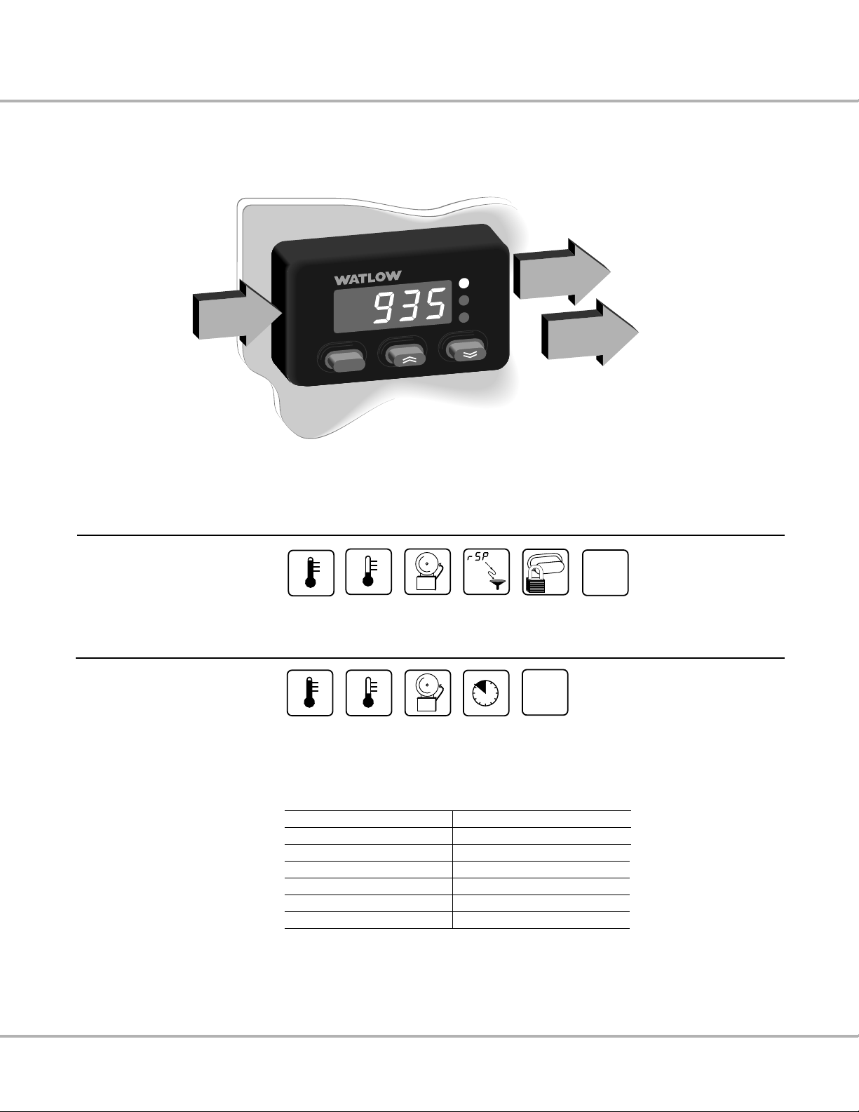
Single
Input
Dual Output
Single Input
Type J, K, T, N, S, E Thermocouple, 1° RTD, or 0.1° RTD
Output 1
Switched dc
Heat Cool Alarm Remote
Set Point
SET
Front
Panel
Lockout
NONE
None
Heat Cool Alarm
30
15 45
0
Timer
(Hr:Min or
Min:Sec)
NONE
None
Output 2
Electromechanical Relay, Switched
dc or Solid-state Relay
Table 1 - Valid Output Functions
First select Output 1: Then select Output 2:
Heat None, Cool, Alarm, Timer
Cool None, Heat, Alarm, Timer
Alarm None, Heat, Cool
Remote Set Point Heat, Cool
Front Panel Lock Heat, Cool, Alarm
None Heat, Cool, Alarm
• The function of Output 1 determines
the options available for Output 2.
• First select the function of Output 1.
Refer to the table (right), then select
the function of Output 2.
Figure 1 - Series 935A Input and Output Overview
Page 6

4 Watlow Series 935A User’s Manual
Read or change
You can simply:
• Read the normally displayed actual temperature,
or…
• Press and hold ß to read the set point,
or…
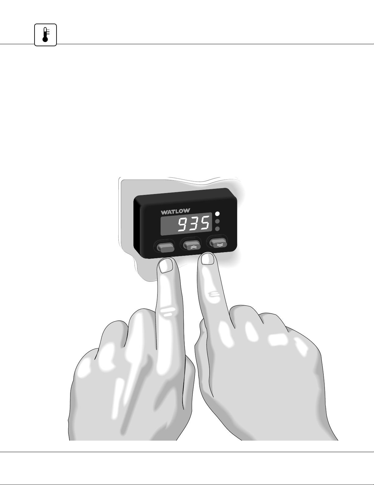
1. Press and hold . and , simultaneously for three seconds to move to a software menu.
2. Press and hold ß to display a choice or value.
3. While continuing to press ß, press . or , to choose new data or select a new value.
4. Release ß and the arrow key to complete the change.
NOTE: The normally displayed actual temperature and set point can be altered to show different combinations of actual
temperature, set point temperature, or time in hours:minutes or minutes:seconds. See [dISP] p. 16.
Page 7
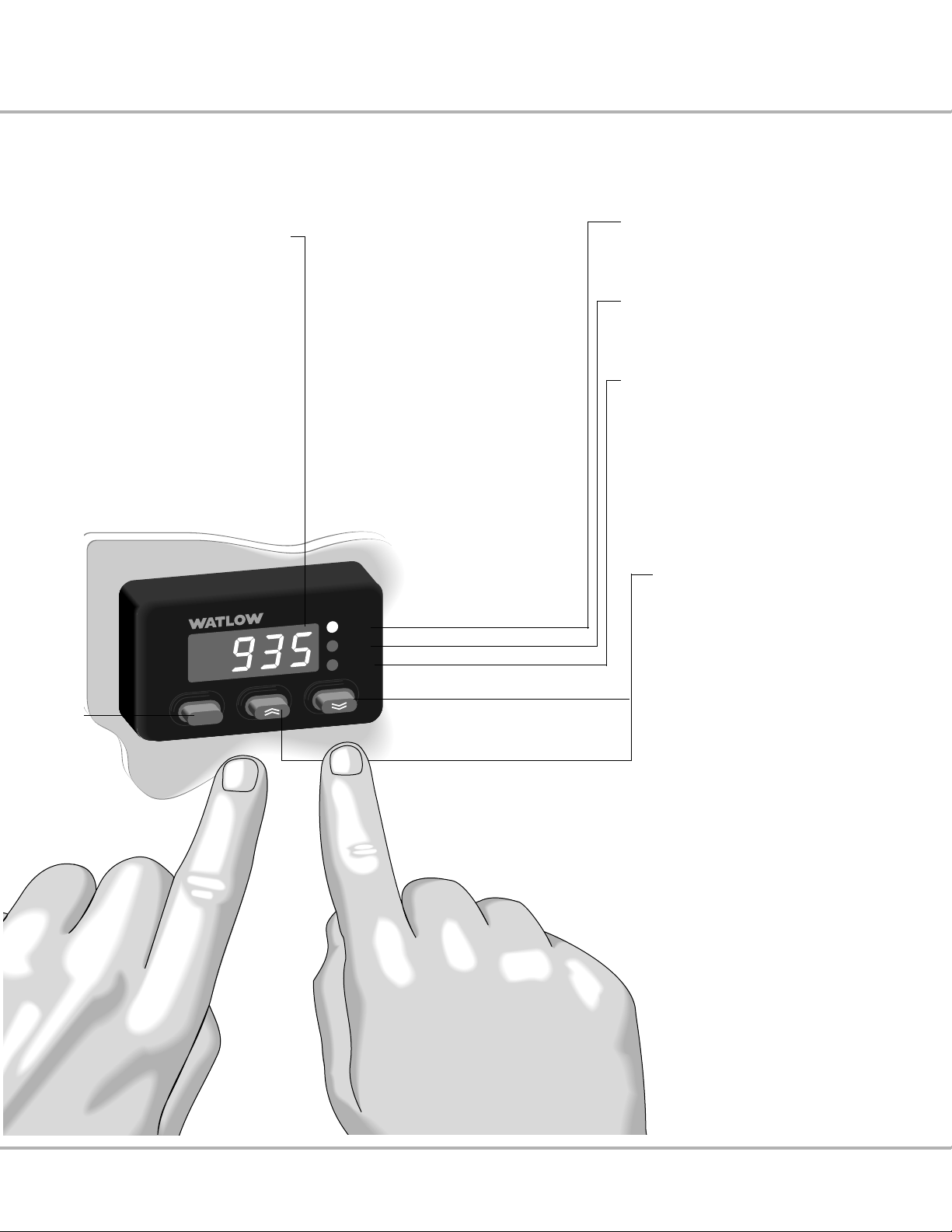
RDY
2
1
SET
Seven-segment
alphanumeric display:
• Shows process value,
set point information, time, or
• Shows prompt name or value,
depending on the key
combination pressed.
Set Key: ß
• Configurable to shift between
normally-displayed value and set
values. See [dISP], p.16.
• Clears a latched alarm.
LED 1:
Lit when Output 1 is active.
LED 2:
Lit when Output 2 is active.
RDY:
Lit when the process temperature
is inside the timer ready band.
Up / . (Increment)
Down / ,
(Decrement) Arrow Key:
• Selects new information when Set
Key is pressed.
• Steps through software menus and
parameters.
• Starts and stops the timer.
• To set up the control, go to the
Easy Software Map, p. 9.
Figure 2 - Series 935A Front Panel Functions
Watlow Series 935A User’s Manual 5
Page 8
6 Watlow Series 935A User’s Manual
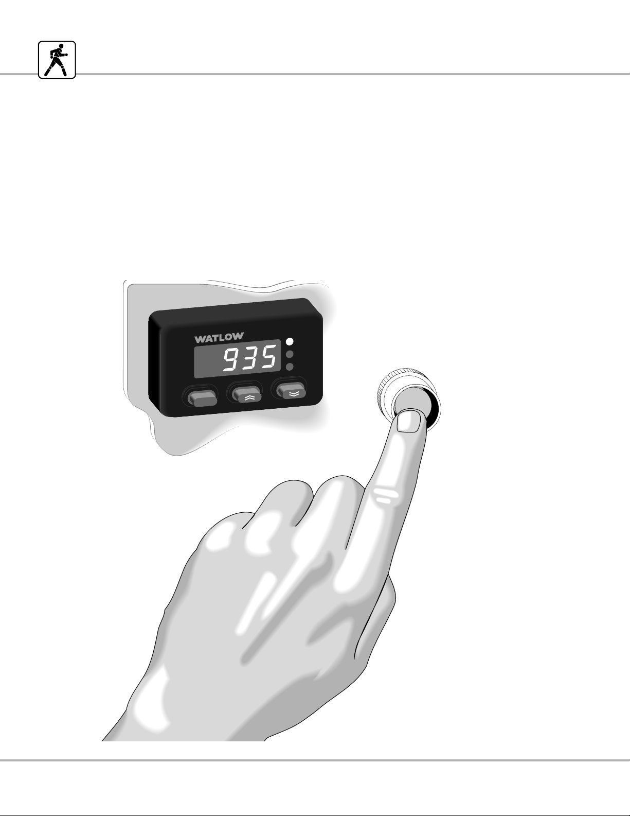
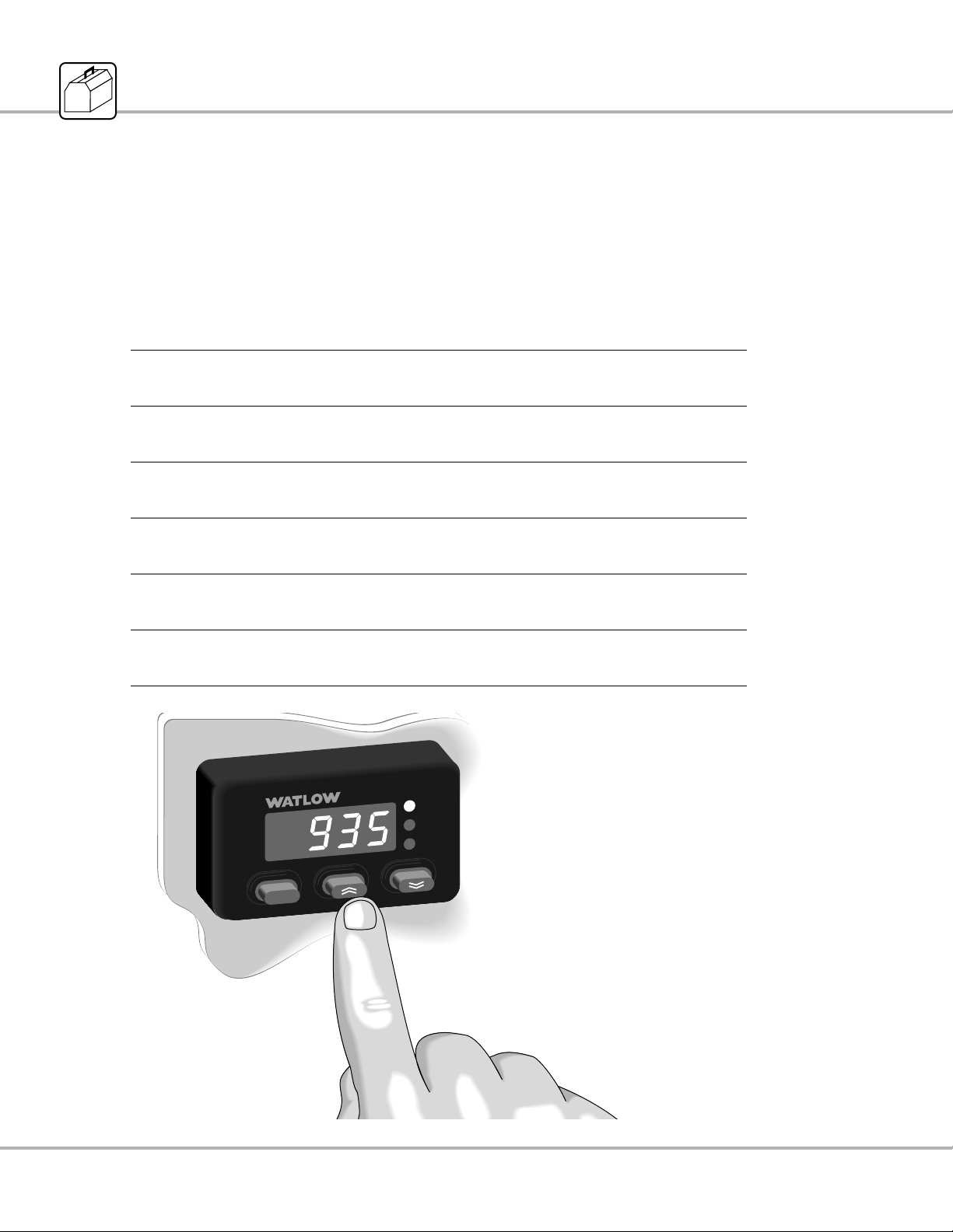
Begin Controlling
1. Apply power to the system.
A properly-wired Series 935A will begin controlling the thermal system as soon as you apply power to it.
2. Look at the Series 935A’s display. It is reading actual temperature, set point temperature, or time.
• To change set point, go to p. 7.
• The Series 935A will auto-tune when you tell it to, go to p. 32.
• If you see an error, go to p. 8.
System
Power
RDY
2
1
SET
Figure 3 - Begin Controlling
Page 9
Watlow Series 935A User’s Manual 7
Change Set Point
RDY
2
1
SET
Your Series 935A displays the actual process temperature when it comes from the factory. You can change it to normally display
the set point or time. Go to p. 16, see [dISP].
1. Press and hold ß.
2. Press one of the arrow keys to alter the set point either upward or downward.
3. Release ß to complete the change.
Figure 4 - Changing the Set Point
Page 10
8 Watlow Series 935A User’s Manual
Respond to a simple error
Display Probable Cause Recommended Action
Reversed thermo- Change the sensor
couple connection leads on Terminals
+ to –. 1 and 2.
Sensor type Go to {`In} prompt, check
mismatch selection (see p. 20), or check
or open RTD. RTD, replace as necessary.
Sensor type Go to {`In} prompt,
mismatch. check selection
(see p. 20).
Open Thermocouple, Check the sensor,
bad connection, or replace as
broken wire. necessary.
Electrical noise. Cycle power to system. See if error
clears. Check system for electrical
interference.
Control is inoperable. Check for line voltage at
terminals 7 and 8.
RDY
2
1
SET
• Simply correct the cause.
• Errors are non-latching
and self-clearing.
• For advanced error and
troubleshooting
information, go to p. 37.
If You See An Error Code:
1. Be aware that most errors are input (sensor) related.
2. Read the table below and follow its recommendations.
Table 2 - Error messages and recommended action
[`Er1]
[`Er2]
[`Er3]
[`Er4]
[`Er5]
[````]
Page 11
Watlow Series 935A User’s Manual 9
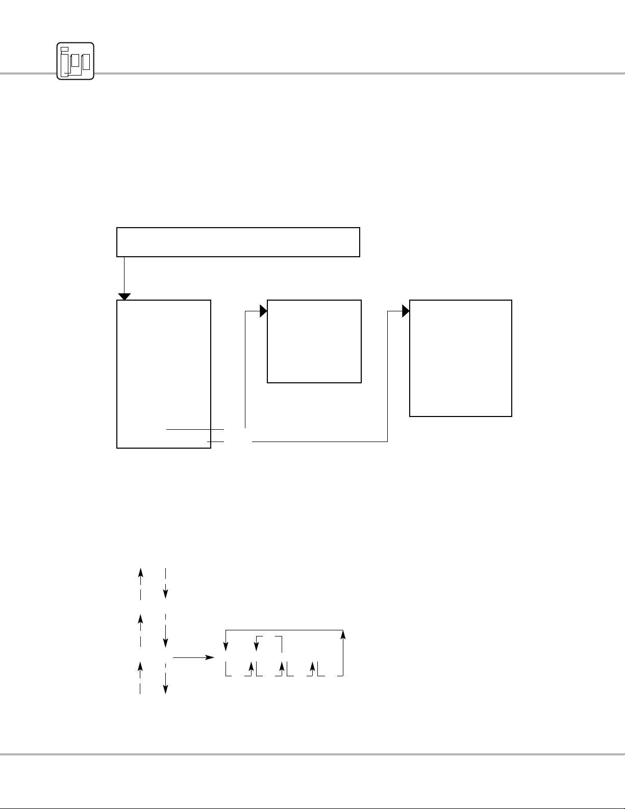
Software Organization
• The Series 935A has three primary menus in addition to a normal display.
• The software reverts to the normal display after 60 ± 5 sec.
Table 3 - Software Organization
• At the [`pid] or [Cnfg] prompt, press and hold the ß key, and the . or , key to select [`yes]. Release the keys to
move to the new menu.
Navigation Example
Learn the Software Map
,
,
,
• To access the Operations Menu, press the
. and , keys simultaneously for three seconds.
• Move through each menu with the . or , key.
• Make changes by pressing and holding the ß key, and
then the . or , key to select a new choice or
value. Release the keys to complete the change.
• To exit any menu: Press and hold the
. and , keys for three seconds,
or
the display will revert to normal display
after 60± 5 seconds.
[Prnc] [Prno [dEnc [dEno
[`Ot2]
[disp]
[Alty]
,
.
.
.
,,,,
Display
Actual Temperature, Set Point, or Time Remaining
Operations, p. 10
Start / Stop:
•Autotune
Set:
•Alarm Ranges
•Countdown Timer
•Idle after Timer
Select
Set Point Type:
Go to:
PID Menu
Configuration Menu
[`yes]
[`yes]
PID, p. 12
Set:
•Heat PID Functions
•Dead Band
•Cool PID Functions
•Calibration Offset
Configuration, p. 16
Set:
•Inputs / Functions
•Output Types
•Display Default
•Alarms / Functions
•Timer Functions
•Failure Mode
•Lockout Functions
Page 12

10 Watlow Series 935A User’s Manual
The Series 935A Operations Menu is the first menu you encounter when you press the . and , keys simultaneously for three
seconds. The Operations Menu provides a location to initiate the following actions or complete the following tasks:
• Auto-tune [`Aut]: Start or stop the auto-tuning process. Auto-tuning selects a set of viable proportional, integral, and derivative
values for heat and/or cool output.
• Alarm Points, [`ALO] and [`AhI]: Select the values for the high alarm point and the low alarm point. Alarm points, dependent
on sensor type high and low ranges, reside in the Operations Menu for easy access.
• Timer Countdown Time [tMr]: Select a countdown time value between 00:00 and 99:59 hours:minutes or minutes:seconds.
Time interval choices [thM] and [tMS] reside in the Configuration Menu for Output 2.
• Idle Set Point [IDLE]: [trAc] or an adjustable value between [``rL] and [``rh]. Choose to have the Idle Set Point track
[trAc], or equal, the Primary Set Point; or select an Idle Set Point value in °F or °C between the range low [``rL] and range
high [``rh] values. The Idle Set Point is active both before and after the timing sequence. The normal or Primary Set Point controls during the timing sequence.
• Local/Remote Set Point [`L-r], [```L] or [```r]: Choose to maintain control with the Primary [```L] (local) Set Point, or to
enable the Remote [```r] Set Point if the Output 1 [`Ot1] choice equals Remote Set Point [`rSP].
• Go to the PID Menu [`Pid]: Choose [`YES] to proceed to the PID Menu.
• Go to the Configuration Menu [CnFg]: Choose [`YES] to proceed to the Configuration Menu.
The table on the next page presents this information in graphic form.
NOTE: Not every prompt listed here or on p. 11 in the Operations Menu will appear in your unit. Prompts vary with
lockout function and output set-up. Whether or not prompts appear in the Operations Menu depends on two features of
the Series 935A:
• Lockout function; the Lockout Tag [`tAg] function masks prompts from view in the various menus. (If you cannot see a prompt,
you can make no change.) See Using Lockout Functions, p. 18, for more information.
• Output 1 and 2 Configuration; some outputs are mutually exclusive. For example, if Output 1 is Alarm, then Output 2 cannot be
Timer. Therefore, the Operations menu will have no timer-related prompts. See the Valid Output Functions Table, p. 3, or Setting
Up Inputs and Outputs, p. 20.
Learn the Operations Menu
Page 13

Watlow Series 935A User’s Manual 11
Table 4 - Operations Menu Overview
To enter the Operations Menu, press the . and , keys simultaneously for three seconds.
Auto-tune - Start the auto-tune action to automatically select a set of viable PID values; [tunE] will flash during auto-tuning.
[``no] [`YES]
NO YES
Alarm Low - Select a low alarm point, adjustable between Off, Range Low and Alarm High.
[`AhI]
Alarm High
Alarm High - Select a high alarm point, adjustable between Alarm Low and Range High, or OFF.
[`ALO]
Alarm Low
Countdown Timer - Select a countdown time duration.
[0)º0] [9959]
00:00 to 99:59 Hrs:Min or Min:Sec
Idle Set Point Type - Choose to track set point, or select a separate idle set point adjustable between Range Low and Range High. When [`Ot1]
= [thM] or [tMS], view the idle set point from the set point display with a three second ßpress.
[trAc] [``rL] [``rh]
Track Range Range
Set Low High
Point
Local / Remote Set Point - Choose to use the remote set point input.
[```L] [```r]
Local Remote
PID Menu - Go to the PID Menu.
[``no] `YES]
NO YES
Configuration Menu - Go to the Configuration Menu.
[``no] `YES]
NO YES
[`Aut]
[`ALO]
[`AhI]
[tMr]
[IDLE]
[`L-r]
[`Pid]
[CnFg]
Page 14

12 Watlow Series 935A User’s Manual
Choose the PID Strategy
You may rely solely on the Auto-tune [`Aut] function (p. 32) and factory defaults to determine PID values for your system, or you may
use auto-tuning and additional manual adjustments. You must select dead band [``db] and calibration offset [`CAL] values manually.
The Series 935A PID Menu is the first sub-menu you encounter after moving to the Operations Menu. The PID Menu provides a software location to select the individual heat or cool proportional band, hysteresis, and cycle time values; and the dead band, integral,
derivative, and calibration offset values.
To go to the PID Menu:
1. Go first to the Operations Menu by pressing . and , simultaneously for three seconds.
2. Scroll through the Operations Menu with , until you see the [`Pid] prompt.
3. While pressing ß to display [``no], choose [`YES] with . or ,.
4. Release ß to see the first PID prompt.
NOTE: Access to the PID Menu and the prompts there varies with lockout function and output set-up. The PID Menu is
locked out when the 935A leaves the factory.
• Lockout function; the Lockout Tag [`tAg] function masks menus from view (if you cannot see a prompt, you can make no
change). See Using Lockout Functions, p. 18.
• Output set-up; you must choose [hEAt] or [COOL] in either Output 1 or Output 2 to have access to the PID Menu. With a [hEAt]
only choice, [COOL] prompts are not visible, and vice versa. See the Valid Output Functions Table, p. 3, or Setting Up Inputs and
Outputs, p. 20.
NOTE: Proportional Band, Integral, Derivative, Dead Band, and Calibration Offset values are adjustable in whole or tenth
°F or °C, depending on input type [``In] and [`C_F] Celsius/Fahrenheit Configuration Menu choices.
Learn the PID Menu
Page 15

Watlow Series 935A User’s Manual 13
Set the PID Menu Values
• Proportional Band, Heat and Cool [Pb`h] and [Pb`c]: Select a value (degrees) to set up band on either side (±) of the
Primary Set Point in which the heat and/or cool proportioning function(s) will be active.
For on/off control, set [Pb`h] or [Pb`c] = 0.
Range: 0 to 999°F/555°C, or 0.0 to 999.0°F/555.0°C
Default: 25°F/17°C, or 25.0°F/17.0°C
• Hysteresis, Heat and Cool [hYSh] and [hYSc]: For use with on/off control only. Select the value (degrees) for the process vari-
able change required to re-energize the control heat and/or cool output.
For ON/off control, set [Pb`h] or [Pb`c] = 0.
Range: 1 to 999°F/555°C, or 0.1 to 999.0°F/555.0°C
Default: 3°F/2°C, or 3.0°F/2.0°C
• Cycle Time, [Ct`h] and [Ct`c]: Select the value (seconds) required for the heat and/or cool output(s) to complete a full ON
through off cycle.
Range: Switched dc/Solid State Relay: 0.1 to 60.0 seconds
Default: 5.0 seconds
Range: Electromechanical Relay: 5.0 to 60.0 seconds
Default: 30.0 seconds
• Dead Band [``db]: Dead Band adjusts the effective cool set point above the primary set point by the Dead Band value in de-
grees. This creates a band between the heating and cooling proportional bands where only integral and derivative activity will
occur. For more information on Dead Band fine tuning, go to p. 33.
Range: 0 to 999°F/555°C, or 0.0 to 999.0°F/555.0°C
Default: 0°
• Integral [``It]: Select a value (minutes/repeat) for the integral function. Integral is the inverse of Reset; It(value) =
1/Reset(value).
Range: 0.00 to 99.99 minutes/repeat
Default: 5.00 minutes/repeat
• Derivative [``dE]: Select a value (minutes) for the derivative function.
Range: 0.00 to 9.99 minutes
Default: 0.00 minutes
• Calibration Offset [`CAL]: Eliminates the difference between the displayed process temperature and the actual process temper-
ature value.
Range: -999 to 9999°F/C, or -99.9 to 999.9F/C
Default: 0°
Page 16

14 Watlow Series 935A User’s Manual
Table 5 - PID Menu Overview
Set-Up Heat
Proportional Band Heat - Select a heat proportional band value.
[```0] [`999] [```0] [`555] [``)0] [99(0] [``)0] [55%0]
0°F to 999°F, or 0°C to 555°C, or 0.0°F to 999.0°F, or 0.0°C to 555.0°C
Hysteresis Heat - Select a heat ON/off control switching hysteresis.
[```1] [`999] [```1] [`555] [``)1] [99(0] [``)1] [55%0]
1°F to 999°F, or 1°C to 555°C, or 0.1°F to 999.0°F, or 0.1°C to 555.0°C
Cycle Time Heat - Select a cycle time for the heat output.
[``)1]
[`6)0] [``%0] [`6)0
0.1 to 60.0 seconds 5.0 to 60.0 seconds
(SSR or Switched dc) (Electromechanical Relay)
Dead Band - Select a dead band value.
[```0] [`999] [```0] [`555] [``)0] [99(0] [``)0] [55%0]
0°F to 999°F, or 0°C to 555°C, or 0.0°F to 999.0°F, or 0.0°C to 555.0°C
Set-Up Cool
Proportional Band Cool - Select a cool proportional band value.
[```0] [`999] [```0] [`555] [``)0] [99(0] [``)0] [55%0
0°F to 999°F, or 0°C to 555°C, or 0.0°F to 999.0°F, or 0.0°C to 555.0°C
Hysteresis Cool - Select a cool ON/off control switching hysteresis.
[```1] [`999] [```1] [`555] [``)1] [99(0] [``)1] [55%0
1°F to 999°F, or 1°C to 555°C, or 0.1°F to 999.0°, or 0.1°C to 555.0°C
Cycle Time Cool - Select a cool output cycle time.
[``)1] [`6)0] [``%0] [`6)0
0.1 to 60.0 seconds 5.0 to 60.0 seconds
(SSR or Switched dc) (Electromechanical Relay)
[Pb`h]
[hySh]
[Ct`h]
[``db]
[Pb`c]
[hySc]
[Ct`c]
Learn the PID Menu - Details
Page 17

Watlow Series 935A User’s Manual 15
Set-Up General
Integral Function - Select an integral value.
[`)00] [9(99]
0.00 to 99.99 minutes/repeat
Derivative Function - Select a derivative value.
[`)00] [`(99
0.00 to 9.99 minutes
Calibration Offset - Select a calibration offset value.
[-999]] [9999] [-9(9] [99(9
-999° to 9999°F or C or -99.9° to 999.9°F or C
Note: Access to the PID Menu and the prompts there varies with lockout function and output set-up. The PID Menu is
locked out when the 935A leaves the factory.
• Lockout function; the Lockout Tag [`tAg] function masks menus from view (if you cannot see a prompt, you can make no
change). See Using Lockout Functions, p. 18.
• Output set-up; you must choose [hEAt] or [COOL] in either Output 1 or Output 2 to have access to the PID Menu. With a
[hEAt] only choice, [COOL] prompts are not visible, and vice versa. See the Valid Output Functions Table, p. 3, or Setting Up
Inputs and Outputs, p. 20.
[``It]
[``dE]
[`CAL]
Page 18

16 Watlow Series 935A User’s Manual
The Configuration Menu is the second sub-menu in the Operations Menu. Use it to set Inputs, Ranges, Output Types, Alarms, Timer,
Failure Mode, and Lockouts.
To go to the Configuration Menu:
1. Go first to the Operations Menu by pressing . and , simultaneously for three seconds.
2. Scroll through the Operations Menu with , until you see the [CnFg] prompt.
3. While holding ß to display [``no], choose [`YES] with . or ,.
4. Release ß to see the first [CnFg] prompt, [``In].
5. To leave the Configuration Menu, press . and , for 3 seconds.
Table 6 - Configuration Menu Overview
Input Type - Choose sensor type. See p. 21 for sensor ranges.
[```J] [```H] [```t] [```n] [```E] [```S] [`rtd] [`r†d]
J t/c K t/c T t/c N t/c E t/c S t/c 1.0° RTD 0.1° RTD
Celsius/Fahrenheit - Choose displayed unit of measure.
[``°F] [``°C]
°F °C
Input Range Low - Select lowest displayable set point. Ranges, p. 21.
[``In] [``rh]
Select a value (lowest displayable set point) between
Input Type Range Low and Input Range High.
Input Range High - Select highest displayable set point. Ranges, p. 21.
[``Rl [``In]]
Select a value (highest displayable set point) between
Input Type Range High and Input Range Low.
Output 1 Function - Choose Output 1 type; see Valid Outputs Table, p. 21.
[hEAt] [COOL] [ALM] [`rSP] [`FPL]] [nonE]]
Heat Cool Alarm Remote Front None
Set Point Panel Lock
Output 2 Function - Choose Output 2 type (dependent on Output 1 choice).
hEAt] [COOL] [ALM] [thM] [tMS] [nonE]]
Heat Cool Alarm Timer Timer None
Hr./Min. Min./Sec
Display Default -
Choose the primary (last 2 characters) and secondary (first 2 characters) default displays. Press ßto toggle to the secondary display
for 15 seconds.
[``Ac] [AcSP] [Acti] [tiAc] [tiSP]
No Actual Actual Time Time remaining
secondary temp. temp. remaining Set point temperature
Actual Set point Time Actual
temp. temp. remaining temp.
Alarm Type - Choose alarm type with output action.
[Prnc] [Prno] [dEnc] [dEno]
Process Process Deviation Deviation
normally normally normally normally
closed open closed open
[``In]
[`C_F]
[``rL]
[``rh]
[`Ot1]
[`Ot2]
[dISP]
[ALty]
Learn the Configuration Menu
Page 19

Watlow Series 935A User’s Manual 17
NOTE:
Access to Configuration Menu varies with lockout function. See p. 19.
Alarm Hysteresis - Choose alarm switching band.
[```1[ [`999] [```1] [`555] [``)1] [99(0] [``)1] [55%0]
1°F to 999°F, or 1°C to 555°C, or 0.1°F to 999.0°F, or 0.1°C to 555.0°C
Alarm Latch - Choose latching or non-latching alarms.
A latching alarm requires a ß press to clear it after the alarm condition clears.
[``no] [`YES]
NO YES
Alarm Silencing - Choose to silence alarms on startup, or not.
[`SIL] = [`YES] silence an alarm with a ß press.
[``no] [`YES
NO YES
Failure Mode - Choose output action after a sensor failure.
Bumpless transfer provides a smooth transition to percent power control without output state change.
[bPLS] [-100] [`100]
Bumpless Percent Power
Timer Output Function - Choose output function for the end of the timer.
Delay ON = Turn ON, Delay Off = Turn off, Signal ON = Toggle ON, Signal off = Toggle off
[dLon] [dLoF] [SGon] [SGof]
Delay Delay Signal Signal
on Off On Off
Start Timer Function - Choose the start timer conditions:
[IMd] = Immediate start on a , press; [`rdy] = , press and Actual temp. is inside the Ready Band;
[rdYA] = , press, plus Actual temp. is inside the Ready Band, then acknowledge with a ß press;
[PWr] = immediate start on power-up without waiting for the Ready Band temp. or a , press.
[IMd] [`rdY] [rdYA] [PWr]
Immediate Ready Ready Power
Acknowledge
Timer Ready Band - If [Strt] =[`rdY] or [rdYA], select ready band high/low values.
[```0] [`999] [```0] [`555] [``)0] [99(0] [``)0] [55%0]
0°F to 999°F, or 0°C to 555°C, or 0.0°F to 999.0°F, or 0.0°C to 555.0°C
Signal Time - If [tIM] = [SGon] or [SGoF], select a Signal ON or Signal off time duration to trigger an annunciator or other action at completion of
countdown time.
[```1] [9959]
1 sec. to 99:59 min:sec.
Set Point Lock - Choose to lock the Primary Set Point from change, not view.
[``no] [`YES]
NO YES
Lockout Tag - Choose undisplayable/unchangeable menus; [PCOA] = all locked.
[PCOA] [PCO`] [PC`A] [PC``] [P`OA] [P`O`] [P``A] [P```]
[`COa] [`CO`] [`C`A] [`C``] [``OA] [``O`] [```A] [````]
Choose the menus / function that will not be displayed, and therefore cannot be changed.
P = PID Menu, C = Configuration Menu (except [`tAG]), O = Operations Menu (except [CnFG]), A = Auto-tune.
[AhyS]
[`LAt]
[`SIL]
[FAIL]
[tIM]
[Strt]
[`rdy]
[``St]
[SLOC]
[`tAg]
Page 20

18 Watlow Series 935A User’s Manual
The Series 935A offers three different security, or “lockout,” options. Set up one or all three lockout options in the Configuration Menu.
∫
• Front Panel Lock [`FPL] uses a control output as an input for an external hardware switch; it
requires wiring, see p. 23. Choose Front Panel Lock [`FPL] as an exclusive Output 1 choice.
Output 2 offers heat, cool, or alarm.
• Choose Set Point Lock [SLOC] as the simplest lockout option. It locks the Primary Set Point
from change, but not from view.
• Choose the Security Tag [`tAG] as a means of masking the Series 935A software menus from
view. By selecting all or part of the four-digit binary acronym, [PCOA] (Proportional / Configuration
/ Operation / Auto-tune), you can choose to mask those items from view, and therefore from
change. For example: In the Configuration Menu [`tAG] set-up, if you can see the P, the operator cannot see the PID menu.
• Exceptions to [PCOA] [`tAG] are:
“C” does not lock out [`tAG].
“O” does not lock out [CnFG].
∫
WARNING: When Output 1 is a Front Panel Lock [`OT1] = [`FPL] , the output is energized!
Do not connect a power switching device to Output 1; injury or death or damage to
equipment or property could result.
Configuration Menu
[``In]
Input Type
[`C_F]
Celsius/Fahrenheit
[``rL]
Input Range Low
[``rh]
Input Range High
[`Ot1]
✓
Output 1 Function
[`Ot2]
Output 2 Function
[dISP]
Display Default
[ALty]
Alarm Type
[AhYS]
Alarm Hysteresis
[`LAt]
Alarm Latch
[`SIL]
Alarm Silencing
[FAIL]
Failure Mode
[tIM]
Timer Function
[Strt]
Start Timer
[`rdY]
Timer Ready Band
[``St]
Signal Time
[SLOC]
✓
Set Point Lockout
[`tAG]
✓
Lockout Tag
Using Lockout Functions
Page 21
Watlow Series 935A User’s Manual 19
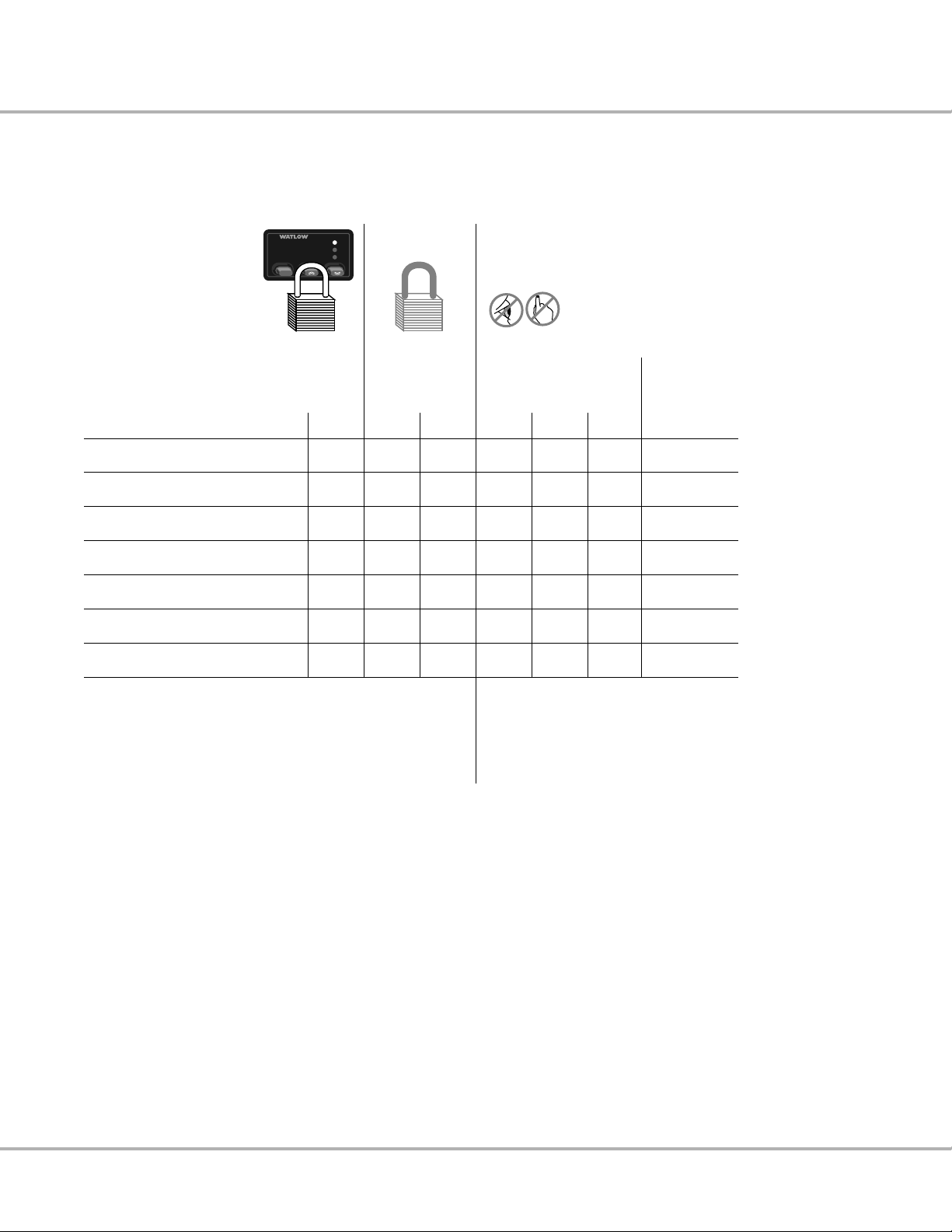
View Process Yes Yes Yes Yes Yes Yes Yes
View Set Point Yes Yes Yes Yes Yes Yes Yes
Change Set Point No Yes No Yes Yes Yes Yes
Auto-tune No
Yes Yes Yes Yes Yes
No
View, Change Operation Menu No
Yes Yes Yes Yes
No Yes
View, Change Configuration Menu
(except tag) No Yes Yes Yes No Yes Yes
View, Change PID No Yes Yes No Yes Yes Yes
= No Lockout
= Fully Locked
= Operator's
Perspective
Set Point LockoutFront Panel Lockout Security Tag
Three
Lockout
Options
Note: Front Panel Lockout requires an external hardware
switch. For [`FPL] set-up and wiring information, see p.
23. For more wiring information, see p. 43.
P = PID Menu
C = Configuration Menu (except [`tag])
O = Operations Menu (except [CnFG])
A = Auto-tune
Table 7 - Series 935A Lockout Options
[`Ot1] [SLOC] [`tAG]
[`fpl]
[`YES] [P```] [`C``] [``O`]
[[```A]
[``no]
[`fpl]
SET
1
2
RDY
[slOC]
[````]
[PCOA]
SP
Page 22

20 Watlow Series 935A User’s Manual
Setting Inputs and Outputs
Key Input/Output Set-up Information
• All initial input and output set-up occurs in the Configuration Menu.
• The 935A requires a thermocouple or RTD input connection to the S1 and S2 Terminals, including
when using the remote set point [`rSP] option.
• Remote Set Point [`rSP] is a second input, wired to OT1 Terminals 3 and 4.
• Indication of °C or °F units of measure occurs only in the [`C_F] prompt.
• Sensor input type minimum and maximum range (see p. 51) is further defined with Range Low
[``rL] and Range High [``rh] to set the working span of set points and remote set point scal-
ing.
• Output 1 and Output 2 configure the prime functions of the Series 935A, they are the “golden”
prompts.
• Output 1 must be heat or cool to use Output 2 as a timer.
• Remote Set Point [`rSP] enables Output 1 to act as an input for 0-5Î (dc) from another con-
troller or a transmitter.
• Front Panel Lock [`FPL] requires an external switch and 62Ω 0.5 watt resistor wired in parallel
on Output 1. Switch open = unlocked; closed = locked. See p. 23.
• Output 2 sets timer interval in hours:minutes [thM]
or minutes:seconds [tMS].
• Display Default [dISP] lets you choose the primary (last 2 characters) and secondary (first 2
characters) default displays. Press ß to toggle to the secondary display for 15 seconds.
[``Ac] = Normal Display: Actual Temperature
Secondary: None
[AcSP] = Normal Display: Set Point Temperature
Secondary: Actual Temperature
[Acti] = Normal Display: Time Remaining
Secondary: Actual Temperature
[TiAc] = Normal Display: Actual Temperature
Secondary: Time Remaining
[tiSP] = Normal Display: Set Point Temperature
Secondary: Time Remaining
Configuration Menu
[``In]
✓
Input Type
[`C_F]
✓
Celsius/Fahrenheit
[``rL]
✓
Input Range Low
[``rh]
✓
Input Range High
[`Ot1]
✓
Output 1 Function
[`Ot2]
✓
Output 2 Function
[dISP]
✓
Display Default
[ALty]
Alarm Type
[AhYs]
Alarm Hysteresis
[`LAt]
Alarm Latch
[`SIL]
Alarm Silencing
[FAIL]
Failure Mode
[tIM]
Timer Function
[Strt]
Start Timer
[`rdY]
Timer Ready Band
[``St]
Signal Time
[SLOC]
Set Point Lockout
[`tAG]
Lockout Tag
Page 23

Watlow Series 935A User’s Manual 21
Input Range Information
J t/c: 32 to 1382°F or 0 to 750°C
K t/c: -328 to 2282°F or -200 to 1250°C
T t/c: -328 to 662°F or -200 to 350°C
N t/c: 32 to 2282°F or 0 to 1250°C
S t/c: 32 to 2642°F or 0 to 1450°C
E t/c: -328 to 1470°F or -200 to 799°C
1° RTD (DIN): -328 to 1292°F or -200 to 700°C
0.1° RTD: -99.9 to 999.9°F or -99.9 to 700.0°C
Table 8 - Setting Inputs and Outputs
Input Type - Choose sensor type.
[```J] [```H] [```t] [```n] [```E] [```S] [`rtd] [`r†d]
J t/c K t/c T t/c N t/c E t/c S t/c 1.0° RTD 0.1° RTD
Celsius/Fahrenheit - Choose displayed unit of measure.
[``°F] [``°C]
°F °C
Input Range Low - Select lowest displayable Set Point, dependent on [``In].
[``In] [``rh] Select a value (lowest displayable set point) between
Input Type Range Low and Input Range High.
Input Range High - Select highest displayable Set Point, dependent on [``In].
[``rL] [``In] Select a value (highest displayable set point) between
Input Type Range High and Input Range Low.
Output 1 Function - Choose Output 1 type.
[hEAt] [COOL] [ALM] [`rsP] [`FPL] [nonE]
Heat Cool Alarm Remote Front None
Set Panel
Point Lock
Output 2 Function - Choose Output 2 type (dependent on Output 1 choice).
[hEAt] [COOL] [ALM] [thM] [tMS] [nonE]
Heat Cool Alarm Timer Timer None
Hr./Min. Min./Sec
Display Default -
Choose the primary (last 2 characters) and secondary (first 2 characters) default displays. Press ß to toggle to the secondary display
for 15 seconds.
[``Ac] [[AcSP]] [Acti] [tiAc] [tiSP]
No secondary Actual temperature Actual temperature Time remaining Time remaining
Actual temperature Set point Time remaining Actual temperature Set point temperature
temperature
Valid Output Functions
First select Output 1: Then select Output 2:
Heat None, Cool, Alarm, Timer
Cool None, Heat, Alarm, Timer
Alarm None, Heat, Cool
Remote Set Point Heat, Cool
Front Panel Lock Heat, Cool, Alarm
None Heat, Cool, Alarm
Note: Access to Configuration Menu varies with lockout function. See p. 19.
• The function of Output 1 determines
the options available for Output 2.
• First select the function of Output 1.
Refer to the table (right), then select
the function of Output 2.
[``In]
[`C_F]
[``rL]
[``rh]
[`Ot1]
[`Ot2]
[dISP]
Page 24

22 Watlow Series 935A User’s Manual
To Set Up Remote Set Point…
1. Wire the control per the example below and the information on p. 42-45.
2. Go to [CnfG], make [`in] and [`c_f] choices, then
3. Make [``In] and [`C_F] choices, then
4. Scale the 0-5VÎ (dc) input with [``rL] and [``rh].
5. Go to [`Ot1], and choose [`rSP].
6. Go to the Operations Menu; [`L-r], choose [```r].
Output 1
[`Ot1] [`rSP] Select Remote Set Point for Output 1
Local / Remote
[`L-r] [```L] Local set point active
[```r] Remote set point active
• Remote Set Point is scaled by [``rh] and [``rL].
• 0V input results in a set point of [``rL].
• 5V input results in a set point of [``rh].
• Adjust [``rL] and [``rh] to match your input to desired set point adjustment.
• The Remote Set Point will display instead of Primary Set Point.
• Auto-tune always uses the Primary Set Point.
• Deviation Alarm uses the active Set Point.
Figure 5 - Remote Set Point Wiring
See p. 42-45 for more wiring information.
NOTE: Sensor required on Terminals 1 and 2.
∫
WARNING: All wiring and fusing must conform to local and national electric codes.
Contact local authorities for further information. Failure to comply with electric codes
could result in injury or death, or damage to property.
Configuration Menu
[``In]
Input Type
[`C-F]
Celsius/Fahrenheit
[``rL]
✓
Input Range Low
[``rh]
✓
Input Range High
[`Ot1]
✓
Output 1 Function
[`Ot2]
Output 2 Function
[dISP]
Display Default
•
•
•
[FAIL]
Failure Mode
[SLOC]
Set Point Lockout
[`TAG]
Lockout Tag
Operations
Menu
[`Aut]
Auto-tune
[`L-r]
✓
Local / Remote
[`Pid]
PID
[CnFG]
Configuration
Set Up Remote Set Point Input
OT1IN OT2
S2
S1
–
+
1
2–3+45678
POWER
Page 25

Watlow Series 935A User’s Manual 23
To Set Up Front Panel Lock…
1. Install an external switch.
2. Wire the control per the example below and the information on p. 42-45.
3. Go to [CnFG], then [`Ot1], and choose [`FPL].
Table 9 - Using Front Panel Lock
Figure 6 - Front Panel Lock Wiring
See p. 43 for more wiring information.
(Closed switch = locked)
∫
WARNING: When Output 1 is a Front Panel Lock [`Ot1] = [`FPL], the output is energized! Do
not connect a power switching device to Output 1; injury or death, or damage to equipment or
property could result.
ç
CAUTION: Failure to install a 60 to 70Ω, 0.5 watt resistor across the customer-supplied Front
Panel Lock switch will cause the panel to lock out even when the switch is open. Injury to
personnel, or damage to equipment or property could result.
Configuration Menu
[``In]
Input Type
[`C_F]
Celsius/Fahrenheit
[``rL]
Input Range Low
[``rh]
Input Range High
[`Ot1]
✓
Output 1 Function
[`Ot2]
Output 2 Function
[dISP]
Display Default
•
•
•
[FAIL]
Failure Mode
[tIM
Timer Function
[Strt]
Start Timer
[`rdY]
Timer Ready Band
[``St]
Signal Time
[SLOC]
Set Point Lockout
[`tAG]
Lockout Tag
[`Ot1] [`FPL]
Set Up Front Panel Lockout
[`Ot1] = [`FPL]
View Process Yes
View Set Point Yes
Change Set Point No
Auto-tune No
Reset Alarm Yes
View or Change Operation No
Menu (Except Config. Menu)
View or Change Configuration No
Menu (Except Tag)
View or Change PID Menu No
1
[`fpl]
SET
2
RDY
OT1IN OT2
S2
S1
–
+
1
2–3+45678
60 to 70Ω 0.5w resistor See Caution
Output 1; Front Panel Lock
POWER
Page 26

24 Watlow Series 935A User’s Manual
Configuration Menu
[``In]
Input Type
[`C_F]
Celsius/Fahrenheit
[``rL]
Input Range Low
[``rh]
Input Range High
[`Ot1]
Output 1 Function
[`Ot2]
Output 2 Function
[dISP]
Display Default
[ALtY]
✓
Alarm Type
[AhYS]
✓
Alarm Hysteresis
[`LAt]
✓
Alarm Latch
[`SIL]
✓
Alarm Silencing
[FAIL]
Failure Mode
Operations
Menu
[`Aut]
Auto-tune
[`ALO]
✓
Alarm Range Low
[`AhI]
✓
Alarm Range High
[`Pid]
PID
[CnFG]
Configuration
Learning Alarms
Alarms signal an excursion from normal operating conditions. In general, audible alarms or lights
connected to alarm outputs will signal a problem. In the 935A the front panel LED “1” or “2” indicates an
alarm with [``hI] or [``LO] flashing on the main display.
• Process alarms use absolute high and low values to trigger an alarm. Use this alarm type if your
process may be subject to temperatures that it must not exceed. Use [`AhI] and [`ALO] to set
alarm points at or near these values. See Table 10: [ALtY], next page.
• Deviation alarms are triggered by a deviation from the set point. The alarm high value [`AhI] is
the deviation above set point, and the low value [`ALO] is the deviation below set point. Whenever
the set point is adjusted, the alarm settings are relative to that value. Deviation alarms use the currently controlling set point, whether primary, remote, idle, or 90% of primary, during auto-tuning. See
Table 10: [ALtY], next page.
• Normally Open, [dEno] or [Prno], Alarms energize the alarm output when an alarm condition
occurs, and de-energize it when cleared. Use this type to activate external devices such as audible
alarms or lights. See Table 10: [ALtY], next page.
• Normally Closed, [dEnc] or [Prnc], Alarms de-energize the alarm output when an alarm condi-
tion occurs, and energize it when the alarm is cleared. Use this type as a “deadman” switch where
system continuity is required for operation. See Table 10: [ALtY], next page.
For example, by running the control output through the alarm output, you can set a normally
closed process alarm to disable the process when the process exceeds the alarm set point.
The alarm output will be off when power is off.
• Alarm Hysteresis sets a point the process must pass on a return (from an alarm condition excur-
sion) to the [`ALO] and [`AhI] points before the alarm can clear. This prevents the alarm output
from “chattering” if the process is hovering around the alarm set point. See Table 10: [AhYS], next
page.
• Latching Alarms require the operator to clear them with a ß press after the process returns to a
safe, or non-alarm condition. Non-latching alarms self-clear. See Table 11: [`LAt], p. 27.
• Silenced Alarms provide a means to clear the alarm output with a ß press even if the alarm
condition still exists. The flashing [``hI] or [``LO] message will persist until the alarm condition
ceases. See Table 11: [`SIL], p. 27. If [`SIL] = [`YES], alarms are disabled (no message or
output) on startup until the safe area is reached.
• Alarm High and Low Points, [`AhI] and [`ALO], in the Operations menu determine where
alarms will trigger. Alarm hysteresis [AhYS] determines where an alarm condition clears. See Table
11, page 27.
• To Clear an Alarm that is latched or “silence-able’ requires the operator to press the ß key after
the process returns to a safe, or non-alarm condition. Non-latching alarms self-clear. See Table 11:
[`LAt] and [`SIL], p. 27.
Table 10 (p. 25) and Table 11 (p. 27) illustrate the Series 935A alarm features.
Page 27

Watlow Series 935A User’s Manual 25
Table 10 - Alarm Functions
Deviation Alarm Process Alarm
[ALtY]
Alarm Type
Non-Alarm State
LED off
Alarm Output:
Alarm State
LED on
Alarm Output Status:
Silenced-Alarm State
LED off
Alarm Output Status:
Power-Off State
LED off
Alarm Output Status:
Function
A deviation alarm
tracks set point.
A process alarm
is a fixed value,
independent
of set point.
[AhYS]
[dEnc] [dEno] [Prnc] [Prno]
Deviation
normally
closed
Deviation
normally
open
Alarm High Region
[AhYS]
Set Point
Safe
Area
[AhYS]
Alarm Low Region
Alarm Hysteresis is the change in the process variable (actual)
required to clear the alarm relay after an alarm occurs.
Process
normally
closed
0
Process
normally
open
Alarm High Region
[AhYS]
Safe
Area
[AhYS]
Alarm Low Region
Page 28

26 Watlow Series 935A User’s Manual
1. Plan an alarm strategy. What do you want to happen when an alarm occurs?
2. Wire the appropriate control output, Output 1 or Output 2, and associated switching and annuncia-
tors. See p. 42-45 for wiring information.
3. Go to the 935A’s Configuration Menu [CnFG]. See p. 16.
4. Set either Output 1 [`Ot1] or Output 2 [`Ot2] as the [ALM] output.
5. Set Alarm Type [ALty].
6. Set alarm hysteresis [AhYS].
7. Set alarm latching [`LAt].
8. Set alarm silencing [`SIL].
9. Set a failure mode [FAIL]. See p. 36-37.
10. Go to the 935A’s Operation Menu. See p.10.
11. Set the alarm high and low [`ALO] and [`AhI] points.
12. Test and adjust the alarm system.
13. Document the alarm settings and system.
ç
CAUTION: Verify, in Table 10, p. 25, the alarm state / alarm output condition you want before
making the Alarm Type [ALty] choice. Failure to do so could result in damage to equipment
and property.
ç
WARNING: Do not rely on the Series 935A alarms to provide redundant temperature limit
control. Use correctly specified, properly installed temperature limit controls instead. Failure
to do so could result in injury, death or damage to equipment and property. (See
accompanying Watlow Bulletin 89.4.3.)
To Clear a Series 935AAlarm
In general, press the ß key to clear a latched or ‘silence-able’ ([`sil] = [yes]) alarm.
Ultimately, the system process value must return within the safe area for the alarm to remain clear. Non-
latching alarms self-clear.
Configuration Menu
[``In]
Input Type
[`C_F]
Celsius/Fahrenheit
[``rL]
Input Range Low
[``rh]
Input Range High
[`Ot1]
Output 1 Function
[`Ot2]
Output 2 Function
[dISP]
Display Default
[AltY]
✓
Alarm Type
[AhYS]
✓
Alarm Hysteresis
[`LAt]
✓
Alarm Latch
[`SIL]
✓
Alarm Silencing
[FAIL]
Failure Mode
Operations
Menu
[`Aut]
Auto-tune
[`ALO]
✓
Alarm Range Low
[`AhI]
✓
Alarm Range High
[`Pid]
PID
[CnFG]
Configuration
Setting Alarms
Page 29

Table 11 (below) and Table 10 (p. 25) illustrate the Series 935A alarm features.
Table 11 - Alarm Functions
Watlow Series 935A User’s Manual 27
[`lat]
Latching alarm
[`sIl]
Silence alarm
[`alO]
Alarm Low
[``no]
An unlatched alarm self-clears
when actual temperature returns
to within the safe area.
[``no]
With this selection, an alarm
cannot be silenced at the 935A
front panel (unless the alarm
is latched [ [~LAt] = [yes] ],
and the alarm condition
no longer exists).
A value from input Range Low to [`AhI].
At the Range Low value, a , press
displays [`off] and [`ahi] disables.
[`yes]
A latched alarm requires the
operator to press the ß
key to clear after the actual
temperature returns to within
the safe area.
[`yes]
With this selection, an alarm
can be silenced by pressing the
ß key. [yes] provides automatic
alarm silencing on start up.
SET
SET
[`ahI]
Alarm High
A value from [`alo] to input Range High
At the Range High value, a . press
displays [`off] and [`ahi] disables.
Page 30

28 Watlow Series 935A User’s Manual
Configuration Menu
[``In]
Input Type
[`C_F]
Celsius/Fahrenheit
[``rL]
Input Range Low
[``rH]
Input Range High
[`Ot1]
Output 1 Function
[`Ot2]
✓
Output 2 Function
[dISP]
✓
Display Default
[ALtY]
Alarm Type
[AhYS]
Alarm Hysteresis
•
•
•
[tIM]
✓
Timer Function
[Strt]
✓
Start Timer
[`rdY]
✓
Timer Ready Band
[``St]
✓
Signal Time
Operations
Menu
[`Aut]
Auto-tune
[tMr]
✓
Countdown Timer
[IdLE]
✓
Idle
• The timer requires Output 1 to work as either a heat or as a cool output.
• The 935A timer is a function of Output 2, which, depending on your unit’s model number, can be ei-
ther switched dc, electromechanical relay, or solid state relay.
• Hours: minutes (hh:mm) or minutes:seconds (mm:ss) choices reside in Output 2 [`Ot2].
• Timer set-up occurs in two locations, in the Configuration Menu and the Operations Menu.
• , starts the timer.
• . stops the timer.
• [dISP] choices set up the timer display (see p. 16).
• LED colon flashes when timer runs.
LED colon ON steadily when timer is not running.
Configuration Menu set-up includes: (see p. 16)
• Output 1 [`Ot1]; heat [hEAt] or cool [COOL].
• Output 2 [`Ot2]; timing interval,
hours:minutes [thM], or minutes:seconds [tMS].
• Timer (Output 2) function [tIM] can perform one of four possible actions after timing:
1. Turn ON, also called, “delay ON” [dLon].
2. Turn off, also called, “delay off” [dLof].
3. Toggle ON, also called, “signal ON” [sgon].
4. Toggle off, also called, “signal off” [sgof].
• Start timer function [Strt] choices:
1. Immediately start [IMd].
2. Start once inside a ready band [`rdy].
3. Start once inside a ready band, acknowledging [rdya] with a ß press.
4. Start immediately on control power up [PWr] without waiting for the Ready Band temp. or a
, press.
• Ready band width [`rdy] above and below set point: degrees.
• Signal time [``St] (if applicable) duration: seconds.
Operations Menu set-up includes: (see p. 10)
• Countdown Time [tMr]:
hours:minutes or minutes:seconds.
• Idle Set Point Type [IdLE], two choices:
1. Track primary set point (always controls at the set point value).
2. Set an idle set point for control when not timing.
The next page presents this information in graphic format with additional detail.
30
15 45
0
Learn the Countdown Timer
Page 31

Watlow Series 935A User’s Manual 29
Table 12 - Series 935A Timer Functions/Settings
Configuration Menu
Choose time in hr:min or min:sec.
Timer set-up
available only when
= or
Output 2
Timer Output
Function;
Choose one of four
possible output
actions for the end
of the timer
/
time periods.
Start Timer
Function
Timer Ready
Band
Operations Menu
Delay ON
Output 2 is
ON before
timing; OFF
during timing; ON
after timing.
Timer starts immediately on a key press at the normal display
without waiting for the Ready Band temperature.
Timer only runs in the Ready Band. key starts timer sequence.
Ready Acknowledge. key starts timer sequence. must be
pressed once inside the Ready Band to start timer at the normal display.
Timer starts immediately on control power up without waiting for the
Ready Band temperature or a , press. See p. 61.
SP
• = 0, Disables Ready feature.
• The RDY front panel LED is lit inside Ready Band for all Timer Start functions.
Signal Time
Timer Function OFF.
Delay OFF Signal ON Signal OFF
Output 2 is
OFF before
timing; ON
during timing; OFF
after timing.
RDY
RDY
RDY
Output 2 is
OFF before
& during
timing; ON
after timing;
then OFF.
Sets the signal time
from 00:01 to 99:59 min:sec
to run after Timer.
Countdown Time
Output 2 is
ON before
& during
timing; OFF
after timing;
then ON.
SET
Idle Set Point
SP
Idle
• Idle is set point used when not timing.
• If Trac selected Idle is the same as Set Point.
• The Set Point value controls the process during the Timer sequence.
Page 32

30 Watlow Series 935A User’s Manual
30
15 45
0
1. Plan a timer strategy.
2. Wire the Output 2 control output, associated switching devices and annunciators. See p. 42-45.
3. Go to the 935A’s Configuration Menu [CnFG].
4. Choose the Output 2 [`Ot2] function as time; hrs:min [thM], or time; min:sec [tMS].
5. Choose a display default [dISP] (see page 16):
• Actual Temperature only [``Ac]
• Actual; Set Point [AcSP]
• Actual; Time [Acti]
• Time; Actual [tiAc]
• Time; Set Point [tiSP]
6. Choose a Timer Output Function [tIM]:
• Delay ON [dLon]
• Delay off [dLoF]
• Signal ON [sgon]
• Signal off [sgoF]
7. Choose a start timer [Strt] function; either immediate [IMd], ready band [`rdY], Ready
Acknowledge [rdYA], or Power [PWr].
8. If you chose [`rdY] or [rdya], then select a ready band [`rdy] value.
9. If you chose [SGon] or [sgof], then select a signal time [``St] value.
10. Go to the 935A’s Operation Menu.
11. Set the countdown time [tMr].
12. Choose the idle set point [IdLE] to track [trAc] the primary set point, or select a separate idle set
point value between the range high [``rh] and range low [``rL] values.
13. Run the system, and test the timer start with a ß press.
14. Document the timer settings and system.
Configuration Menu
[``In]
Input Type
[`C_F]
Celsius/Fahrenheit
[``rL]
Input Range Low
[``rh]
Input Range High
[`Ot1]
Output 1 Function
[`Ot2]
✓
Output 2 Function
[dISP]
✓
Display Default
[ALty]
Alarm Type
[AhYS]
Alarm Hysteresis
•
•
•
[tIM]
✓
Timer Function
[Strt]
✓
Start Timer
[`rdY]
✓
Timer Ready Band
[``St]
✓
Signal Time
Operations
Menu
[`Aut]
Auto-tune
[tMr]
✓
Countdown Timer
[IdLE]
✓
Idle
Setting the Countdown Timer
Page 33

Watlow Series 935A User’s Manual 31
30
15 45
0
Convection Oven Application
Scenario
A master chef bakes bread at 350°F for 30 minutes. He wants the oven at the proper temperature with an indication when it is ready to
begin baking. He isn't concerned if the oven is 10° cool at first. After he loads the oven, the chef wants to start the countdown time by
pressing a key. When the baking time is complete, he wants a 10 second audible indication that the bread is done.
Recommended Control
A Series 935A-1CD0-000G control.
• Switched dc Output 1 wired to a dc input solid state relay (SSR) switches the heaters.
• Electromechanical relay Output 2 wired to an AC audible indicator provides “done” indication.
Configuration Menu Set-up
[`C_F] = [``°f] °F
[dIsp] = [Acti] After a ß press, actual temperature appears for 15 seconds.
[`Ot1] = [hEAt] Heating output
[`Ot2] = [tMS] Time; minutes:seconds
[tIM] = [SGon] Output 2 turns ON briefly at the end of the timing cycle.
[Strt] = [rdYA] Timer waits to countdown until temperature deviation from set point < [`rdy] value and the ß key
is pressed.
[`rdY] = [``10] Ready band; 10°F
[``St] = [``10] Output 2 turns ON for 10 sec. at the end of the timing cycle.
Operations Menu Set-up
[tMr] = [3000] Bake time; 30 minutes
[IdLE] = [``75] The set point temperature before a timing cycle starts and after a timing cycle completes.
Set Point = [`350°F
Operator/Control Actions
• With the oven "idling" at 75°F, the chef starts the preheat cycle with a , press. The display immediately shows 30:00 with the
colon ON steadily. The RDY LED is off. Series 935A begins to control to the 350°F bake set point.
• As the actual oven temperature increases to within the Ready Band at 350°F ±10°F, the RDY LED turns on. The chef loads the
oven and presses ß to acknowledge the Ready Band and thereby start the bake cycle.
• Time starts counting down. Actual temperature displays for 15 seconds after the ß key is press. Then time displays with the
colon flashing.
• If temperature deviates out of the Ready Band (less than 340°F or more than 360°F), timer countdown will pause, but will continue as soon as temperature re-enters the ready band.
• When time reaches 00:00, Output 2 turns on for 10 seconds sounding the audible indicator. The chef can stop the audible indicator by pressing .. The Series 935A then automatically shifts to the 75°F idle set point.
Timer Example
Page 34

Auto-tuning
Auto-tune automatically sets PID parameters for your system.
1. Press . and , for three seconds.
2. You'll see [`Aut].
3. Press and hold ß, then select [`YES] with . or ,. [tune] will flash to indicate auto-tun-
ing. Display reverts to normal after auto-tuning.
4. [`Aut] = [``no] stops auto-tuning.
Figure 7 - Auto-tuning the Series 935A
Manual Tuning
For optimum performance, tune the Series 935A to your thermal system. The settings here are for a
broad spectrum of applications; your system may have different requirements.
Tune heating outputs at a set point above ambient temperature.
Tune cooling outputs at a set point below ambient temp.
1. Apply power to the 935A and enter a set point.
In the Operations Menu, [`Aut] must = [``no].
Begin with these Configuration Menu settings:
[Pb`h = [```1], [``1t] = [`000], [``dE] = [`000],
[Ct`h] = [`%0]], [`CAL] = [```0].
2. Proportional Band Adjustment: Gradually increase [Pb`h] until the upper display temp. stabilizes
at a constant value.
3. Integral Adjustment: Gradually decrease [``It] from 30.00 until the display temperature begins to
oscillate or “hunt.” Then slowly increase [``It] until the upper display stabilizes again near set
point.
4. Cycle Time Adjustment: Set [Ct`h] as required. Faster cycle times sometimes achieve the best
system control. However, if a mechanical contactor or solenoid is switching power to the load, a
longer cycle time will minimize wear on relays.
5. Derivative Adjustment: Increase [``dE] to 0.10 minute. Then raise set point by 20° to 30°F, or 11°
to 17°C. Observe approach to set point. If load temperature overshoots, increase [``dE] by 0.50
minute. Raise set point by 20 to 30°F, or 11 to 17°C and watch approach again. Repeat until sys-
tem rises to new set point appropriately.
6. Calibration Offset Adjustment: Enter the [`CAL] offset value you want. Calibration offset adds or
subtracts degrees from the value of the input signal.
Temperature
Time
90%
Set Point
32 Watlow Series 935A User’s Manual
Auto-tuning
NOTE:
[`Aut] is
not visible at
factory default.
ç
CAUTION:
Successful Series
935A auto-tuning
requires 3
oscillations thru the
90% set point in 85
min. or less. If the
system cannot
perform the
oscillations in that
time, the control will
revert to the
previous PID values.
NOTE:
Manual tuning is a
slow procedure,
taking from minutes
to hours to obtain
optimum value.
Operations Menu
[`Aut]
✓
Auto-tune
[`ALO]
Alarm Range Low
[`Ah1]
Alarm Range High
[tMr]
Countdown Timer
[IdLE]
Idle
[`L-r]
Local / Remote
[`Pid]
PID
[CnFg]
Configuration
ç
Auto-tuning occurs at 90% of set point
in less than or equal to 85 minutes.
Page 35

Watlow Series 935A User’s Manual 33
Fine Tune the PID Settings
1. Set [Pb`h] and [Ct`h] in degrees.
2. If Proportional Band Heat [Pb`h] = 0, Set Hysteresis Heat [HySh]. The Series 935A will provide on/off
control with the hysteresis value selected, and no proportioning action.
3. Proportional Bands should be decreased for tighter control but increased to eliminate oscillations.
4. Cycle Time Heat [Ct`h] is limited to a minimum of 5.0 seconds for the electromechanical relay to help
reduce wear. The electromechanical relay (D, Output 2) is not recommended for PID control. It is warranted to 100,000 contact closures only. Alarm or on/off control are appropriate applications for the
Series 935A's electromechanical relay output.
5. Set Dead Band [``db] to adjust the effective cool set point above the primary set point by the dead
band value in degrees. In cool/heat applications, dead band prevents continuous cool output action by
creating a buffer between heating and cooling output action.
6. Set [Pb`c] and [Ct`c] in degrees.
7. If Proportional Band Cool [Pb`c] = 0, Set Hysteresis Heat [HYSc]. The Series 935A will provide on/off
control with the hysteresis value selected, and no proportioning action.
8. Proportional Bands should be decreased for tighter control but increased to eliminate oscillations.
9. Cycle Time Heat [Ct`h] is limited to a minimum of 5.0 seconds for the electromechanical relay to help
reduce wear. The electromechanical relay (D, Output 2) is not recommended for PID control. It is warranted to 100,000 contact closures only. Alarm or on/off control are appropriate applications for the
Series 935A's electromechanical relay output.
10. Set Integral [``It] to eliminate droop in the system. Lower the value for more droop reduction.
Adjustable from 0 to 99.9 minutes / repeat.
11. Set Derivative [``dE] to prevent overshoot. Increasing the value slows the approach to set point.
Adjustable from 0 to 9.99 minutes.
12. Calibration Offset [`Cal] eliminates the difference between the displayed process temperature and the
actual process temperature value.
PID Menu
Set up Heat:
[Pb`h]
✓
Proportional Band
[hySh]
✓
Hysteresis
[Ct`h]
✓
Cycle Time
[``db]
✓
Dead Band
Set up Cool:
[Pb`c]
✓
Proportional Band
[hySc]
✓
Hysteresis
[Ct`c]
✓
Cycle Time
Set up General:
[``It]
✓
Integral
[``dE]
✓
Derivative
[`CAL]
✓
Calibration Offset
Page 36

34 Watlow Series 935A User’s Manual
Calibrating the 935A
Calibration requires a precision millivolt source with
thermocouple compensation, an adjustable 0-10 volt source,
and a decade resistance box.
• [tr50] and [tr00] calibrate the thermocouple span.
• [``tc] calibrates the ambient compensation.
• [r380] and [r`15] calibrate the RTD span.
• 0V is required when calibrating [tc00] and [r`15]
for remote set point calibration.
• 5V is required when calibrating [tc50] and [r380]
for remote set point calibration.
• When calibrating, calibrate all points for consistency in results.
• Allow the unit to warm up for 15 minutes before calibrating.
Quick Calibration
Restore:
Press all three keys
simultaneously until
[tc50] appears in the
display, press .
once and [`rSt] will
appear in the display.
Press and hold ß,
the display will show
[``no], press . to
change display to
[`YES]. Press and
hold . and ,
for 3 seconds to exit
the [`CAL] menu.
NOTE: Restore
Factory Calibration
[`rSt] = [`YES]
restores factory
calibration
values to all
calibration prompts.
Figure 8a Thermocouple Calibration
Figure 8b RTD Calibration
Calibration Menu
[tc50]
✓
tc50
[tc00]
✓
tc00
[``tc]
✓
tc
[r`15]
✓
r15
[r380]
✓
r380
[`rSt]
✓
rst
OT1IN OT2
S2
S1
–
+2–3+
1
mV
source
mV source = 50.000mV
Volt source = 5V
• Store TC counts at 50.000mV
• Store 5V remote set point
counts for use with TC
mV source = 0.000mV
Volt source = 0V
• Store TC counts at 0.000mV
• Store 0V remote set point
counts for use with TC
mV source = Temp. Compensation
Volt source = 0V
• Store ambient counts
at 32° F. Type J.
45678
Volt
source
POWER
OT1IN OT2
S2
S1
–
+2–3+
1
Decade
Box
Decade Box = 15.00 ohms
Volt source = 0V
• Store low end RTD counts
• Store 0V remote set point
counts for use with RTD
mV source = 380.00 ohms
Volt source = 5V
• Store high end RTD counts
• Store 5V remote set point
counts for use with RTD
• Restore factory calibration
45678
Volt
source
POWER
Page 37

Watlow Series 935A User’s Manual 35
Thermocouple and Remote Set Point Input Field Calibration Procedure
Equipment Required:
• Type “J” Reference Compensator with reference junction at 32°F/0°C, or Type “J” Thermocouple Calibrator set at 32°F/0°C.
• Precision millivolt source, 0-50mV min. range, 0.01mV resolution.
Set Up:
1. Connect 100-240Å (ac), or 24-28V‡ (ac/dc) to Terminal 7 and Terminal 8.
2. Connect the millivolt source to Terminal 1 negative and Terminal 2 positive.
3. Connect voltage source to Terminal 3 negative and Terminal 4 positive.
4. Apply power to the unit and allow it to warm up for 15 minutes.
Move to the Calibration Menu:
1. Press . and , simultaneously for 3 seconds.
2. Press . or , until [CnFG] is displayed.
Press and hold ß – press . or , to select [`YES], then release ß.
3. Press . or , until [`TAG] is displayed.
Press and hold ß. Press . or ,8 times (display shall be blank).
Calibration: (Thermocouple)
1. Press and hold ß, ., and , simultaneously for 3 seconds until [TR50] is displayed.
2. Set the mV source to 50.00mVÎ (dc). Set the voltage source to 5.00VÎ (dc). Allow 10 seconds for sources to stabilize. Press and
hold ß. Press . or , until [`YES] appears. Release ß.
3. Press , - [Tc00] shall be displayed.
4. Set the mV source to 0.00 mVÎ (dc), set voltage source to 0.00VÎ (dc). Allow 10 seconds for sources to stabilize. Press and hold
ß. Press . or , until [`YES] appears. Release ß.
5. Press ,. [``Tc] shall be displayed.
6. Set the MV source to 0.00 mV (if using a temperature compensator). Set calibrator to 32°F/0°C.
Set voltage source to 0.00V. Allow 10 seconds for sources to stabilize.
Press and hold ß. Press . or , until [`YES] is displayed. Release ß.
Calibration: (RTD)
Equipment Required:
• Precision Resistance Box with 0.01Ω Resolution.
1. Remove thermocouple wires from Terminal 1 and Terminal 2.
2. Connect S2 to terminal 1. Connect S1 to Terminal 2.
3. Press ,. [R`15] shall be displayed.
4. Connect voltage source to Terminal 3 negative and Terminal 4 positive.
5. Set the Decade box to 15.00Ω, set the voltage source to 0.00V (Allow 10 seconds for sources to stabilize). Press and hold ß.
Press . or , until [`YES] appears. Release ß.
6. Press , - [R380] shall be displayed.
7. Set the decade box to 380.00Ω, set the voltage source to 5.00V. (Allow 10 seconds for sources to stabilize). Press and hold ß.
Press . or , until [`YES] appears. Release ß.
8. Press and hold . and , for 3 seconds to Exit calibration menu.
Calibrating the 935A and Remote Set Point Input
Page 38

36 Watlow Series 935A User’s Manual
Errors and Troubleshooting
Set up an input failure operation mode at the [FAIL] prompt in the [CnFG] menu; choose bumpless
transfer [bPLS] for smooth output action transition to percent power control, or select a percent power
output value.
[FAIL} [bPLS]
Bumpless Transfer
when errors occur, the control output will continue at
a percent output learned while stable. Default = [bPLS] .
[-100] [`100]
Percent Power
(-100% to +100% , depending on heat/cool
output configuration). The control will assume
a specific output power when input errors occur.
• All except one of the possible displayed
error messages are input related.
• If you see [`Er5], cycle power to the controller.
If the error persists, call the factory.
• Be aware of the difference between U.S and
European thermocouple color/colour codes.
• Reversed polarity input leads is one of
the most common errors.
• Incorrect software input choice at the
Configuration Menu [CnFG] input [``In] prompt
is another common error.
When calling the factory for help, please have:
1. The model number of the control.
2. A photocopy of pages 55 to 62 with the settings
from your control, if possible.
3. Specifications of devices directly interfaced
with the control.
Configuration Menu
[``In]
Input Type
[`C_F]
Celsius/Fahrenheit
[``rL]
Input Range Low
[``rh]
Input Range High
[`Ot1]
Output 1 Function
[`Ot2]
Output 2 Function
[dISP]
Display Default
[ALtY]
Alarm Type
[AhYS}
Alarm Hysteresis
[`LAt]
Alarm Latch
[`SIL]
Alarm Silencing
[FAIL}
✓
Failure Mode
[tIM]
Timer Function
[Strt]
Start Timer
[`rdY]
Timer Ready Band
[``St]
Signal Time
[SLOC]
Set Point Lockout
[`tAG]
Lockout Tag
Page 39

Watlow Series 935A User’s Manual 37
To Troubleshoot Sensor
• Remove sensor wires from Terminals 1 and 2.
• For a thermocouple sensor Series 935A, place a jumper wire on Terminals 1 and 2.
Control should display the ambient temperature at the back of the control.
• For an RTD sensor Series 935A, place a 110 +/- 10Ω resistor on Terminals 1 and 2.
The control should read 100Ω = 32°F, 110Ω = 77°F, 120Ω = 127°F.
• An RTD sensor Series 935A can be configured in software as if it were a
thermocouple unit, and then tested as above.
• You can restore factory calibration [`rST], see p. 34-35.
Table 13 - Error Codes and Actions
Display Probable Cause Recommended Action
Reversed thermocouple Change the sensor A-D
connection + to –. leads on Terminals 1 and 2. under flow
Sensor type Go to In prompt, check selection (see p. 20), Sensor
mismatch or open RTD. or check RTD, replace as necessary. under range
Sensor type Go to In prompt, Sensor
mismatch. check selection (see p. 20). over range
Open Thermocouple, bad Check the sensor, A-D
connection, or broken wire. replace as necessary. over flow
Electrical noise. Cycle power to system. See if error clears.
Check system for electrical interference.
Control is inoperable. Check for line voltage at
terminals 7 and 8.
Table 14 - Troubleshoot Control Outputs
When indications such as significant differences between set point and
actual temperatures point to no output action, check output configurations
as described on p. 23. Check wiring, p. 44.
Measure
Output Terminals Load-on State Load-off State
“C” Output 1 3 & 4 LED 1 on LED 1 off
3.0 to 7.0VÎ (dc) 0.0VÎ (dc)
“C” Output 2 5 & 6 LED 2 on LED 2 off
3.0 to 7.0VÎ (dc) 0.0VÎ (dc)
“D” Output 2 5 & 6 LED 2 on LED 2 off
0VÎ (dc) line voltage.
Load sees line voltage Load sees 0VÎ (dc)
“K” Output 2 5 & 6 LED 2 on LED 2 off
<2VÎ (dc) line voltage
Load sees line voltage Load sees 0VÎ (dc)
[`Er1]
[`Er2]
[`Er3]
[`Er4]
[`Er5]
[````]
Page 40

38 Watlow Series 935A User’s Manual
Mounting
Layout for
four 1/32 DIN knockouts
with punch and die
Figure 9- Panel Cut-out Dimensions
Figure 10- Mounting Layout for Knockouts
Panel Thickness
1.5 mm to 9.7 mm (0.060 to 0.38 in.)
Punch and Die Supplier
Greenlee Textron, Inc., Phone: 1-800-435-0786.
Catalog Number: 50740180; Available: 4-6 weeks, Greenlee distributor.
12.7mm
(0.500 in.)
45.0mm (1.772 in.)
+0.6mm, -0.0mm
(+0.024 in., -0.000 in.)
22.2mm
(0.874 in.)
+0.3mm,
-0.0mm
(+0.012 in.,
-0.000 in.)
12.7mm
(0.500 in.)
57.7mm
(2.272 in.)
34.9mm
(1.374 in.)
Page 41

Watlow Series 935A User’s Manual 39
Dimensions
Figure 11- Series 935A Dimensions
53.1mm
(2.09 in.)
29.0mm
(1.14 in.)
Panel Cutout
44.96mm
101.6mm (4.00 in.)
12.7mm (0.50 in.)
Maximum Overall Depth
114.3mm (4.50 in.)
Panel Thickness
1.5mm to 9.7mm
(0.060 to 0.38 in.)
22.10mm
(0.870 in.)
(1.770 in.)
1
2
Page 42

40 Watlow Series 935A User’s Manual
Installation Procedure
1. Make a panel cutout using the dimensions in Figure 9, p.
38.
2. Insert the 935A into the cutout. Check to see that the gasket
is not twisted. Make sure the rounded side of the D-shaped
external case gasket faces the panel surface, and the
gasket is fully seated in its bezel channel. See Figure 12.
3. While pressing the bezel firmly against the panel, slide the
mounting collar over the back of the control. The tabs on the
collar must line up with the mounting ridges on the case for
secure installation. See Figure 12 again.
4. Slide the collar firmly against the back of the panel, getting it
as tight as possible. Make sure you cannot move the case
within the cutout, if you can, you do not have a IP65/NEMA
4X seal!
5. Make sure you have a tight seal. Use your thumb to lock the
tabs into place while pressing the case from side to side.
Don’t be afraid to apply enough pressure to install the control. The tabs on each side of the collar have teeth which
latch into the ridges. See Figure 12. Each tooth is staggered
at a different depth (from the front) so only one of the tabs
on each side is ever locked into the ridges at any time.
6. Look at Figure 13; you see that the tabs on one side of the
collar correspond with those on the opposite side. Be sure
only the two corresponding tabs are locked in the ridges at
the same time. If the matching tabs are not holding the
case, no IP65/NEMA 4X seal exists. Make a visual check,
or use your finger nail to pull out on each tab. The space between the bezel and panel must be 0 to 0.48 mm (0 to
0.019 in.).
Collar Removal
Slide a thin, wide tool (putty knife) under all three mounting tabs,
top then bottom, while pushing forward on the back of the case.
Figure 12- Mounting, Case Top View and Collar
Cross Section.
Figure 13- Case Rear View and IP65/NEMA 4X Seal
Example
NOTE: To guarantee a proper IP65/NEMA 4X seal, make
sure the gasket between the panel and the rim of the case
is not twisted and is seated properly. Press firmly.
NOTE: Make sure the rounded side of the D-shaped
external case gasket faces the panel surface, and the
gasket is fully seated in its bezel channel. See Figure 12.
Bezel
External
Gasket
0 to 0.483 mm space (0 to 0.019 in.)
Panel
Ridges
Tabs
Mounting Collar
Teeth
Page 43

Figure 14- Terminal Block Removal Procedure
1. Press in on sides of cover to release
the terminal cover hooks.
2. Move your grip rearward slightly, then lift the
terminal cover straight up.
Watlow Series 935A User’s Manual 41
Terminal Block Removal
Page 44

42 Watlow Series 935A User’s Manual
Wiring a 935A
Figure 15 - Wiring the Series 935A
∫
WARNING: All electrical wiring and fusing must conform to local and national electric codes. Contact local authorities for
further information. Failure to comply with electric codes could result in injury or death, or damage to property.
ç
CAUTION: Using grounded thermocouples with non-isolated output switching devices could introduce ground loops into
the control system, and possibly damage the controller and product.
NOTE: Torque terminals to 1.36 Nm (12 in lbs).
Power Wiring Input Wiring
OT1IN OT2
S2
S1
–
+
1
2–3+45678
High Voltage
OT1IN OT2
S2
S1
–
+
1
2–3+45678
Low Voltage
+ -
POWER
100-240
VOLTS
POWER
24-28
VOLTS
S3
OT1IN OT2
S2
S1
–
+
1
2–3+45678
Remote Set Point Input
OT1IN OT2
S2
S1
–
+
1
2–3+45678
2-wire
3-wire
OT1IN OT2
S2
S1
–
+
1
2–3+45678
Thermocouple Input
POWER
POWER
POWER
Page 45

Watlow Series 935A User’s Manual 43
∫
WARNING: All electrical wiring and fusing must conform to local and national electric codes. Contact local authorities for
further information. Failure to comply with electric codes could result in injury or death, or damage to property.
ç
CAUTION: Failure to install a 60 to 70Ω, 0.5w resistor across the customer-supplied Front Panel Lock switch will cause the
panel to lock out even when the switch is open. Injury to personnel, or damage to equipment or property could result.
∫
WARNING: When Output 1 is a Front Panel Lock [`Ot1] = [`FPL], the output is energized! Do not connect a power switching
device to Output 1; injury or death, or damage to equipment or property could result.
NOTE:
Switching inductive loads (relay coils, solenoids, etc.) with the mechanical relay or solid-state relay output options
requires using an R.C. suppressor. Watlow carries the R.C. suppressor Quencharc brand name, which is a trademark of
ITW Pakron. Watlow Part No. 0804-0147-0000.
Output 2 WiringOutput 1 Wiring
See Caution
Internal Circuitry
+5.7 to 8V
Current
Limit
60mA
OT1IN OT2
S2
S1
–
+
1
2–3+45678
Output 2; Solid State Relay; "K"
POWER
OT1IN OT2
S2
S1
–
+
1
2–3+45678
Output 1; Switched DC; "C"
OT1IN OT2
S2
S1
–
+
1
2–3+45678
p
;
POWER
POWER
60 to 70Ω, 0.5w resistor
OT1IN OT2
S2
S1
–
+2–3+
1
45678
Output 2; Electromechanical Relay; "D"
Internal Circuitry
+5.7 to 8V
OT1IN OT2
S2
S1
–
+2–3+4–
1
Output 2; Switched DC; "C"
5+678
Current
Limit
60mA
POWER
Power
Page 46

44 Watlow Series 935A User’s Manual
System Wiring Examples
Figure 16 - Series 935A System Wiring Examples
∫
WARNING: All electrical wiring and fusing must conform to local and national electric codes. Contact local authorities for
further information. Failure to comply with electric codes could result in injury or death, or damage to property.
ç
CAUTION: Using grounded thermocouples with non-isolated output switching devices could introduce ground loops into
the control system, and possibly damage the grounder and product.
L1
120VÅ (ac)
L2
Earth Ground
Series 935
935A-1CD0-000G
OT1IN OT2
S2
S1
–
+
1
2–3+45678
POWER
100-240
VOLTS
Fuse
Coil
12
–
6
5
+
High Limit
Mechanical
Contactor
DIN-a-mite
DA10-24C0-0000
3
®
4
Heater
L1
L2
21 3456789
Series 146
limit control
146E-1601-1000
10 1112 1314 15 1617
High
temperature
light
NOCNC
Reset
Limit SensorProcess Sensor
Optional
Normally
Open
Momentary
Switch
Page 47

Watlow Series 935A User’s Manual 45
Figure 17 - Series 935A Ladder Diagram Wiring Example
∫
WARNING: All electrical wiring and fusing must conform to local and national electric codes. Contact local authorities for
further information. Failure to comply with electric codes could result in injury or death, or damage to property.
L1
1
13
2
3
4
Branch
5
6
7
Circuit Fuse
1
1
1 CR-1
11
8
9
10
11
12
1
17
13
(+)
(-)
120VÅ (ac)
(+)
12
13
14
15
POWER
S2
S1
OT1 OT2
–
+2–3+
1
4(–)
456 78
100-240
VOLTS
5
67
–
2
+
6
5
DIN-a-mite
4
®
DA10-24C0-C000
13
13
14
10
11
1
Com
5
Series 146
146E-1601-1000
Temperature Limit
3
7
9
NO
NC
Heater
1089
1CR
16
Series 935
935A-1CD0-000G
Temperature
Controller
R
18
Hi Temp. Light
L2
2
2
2
2
2
Page 48

46 Watlow Series 935A User’s Manual
Glossary
Alarm
A condition, generated by the controller, indicating that the process has exceeded or fallen below the set or limit point.
Alarm Hysteresis
A change in the process variable required to re-energize the
alarm output.
Ambient Temperature
Temperature surrounding the components of a thermal system.
Auto-tune
Automatically sets PID values to fit a particular thermal system.
Bumpless Transfer
When transferring from auto to manual operation, the control
output(s) will maintain the same output level.
Calibration
Adjusting an instrument to a known value.
Configuration Menu
The second software sub menu of the Series 935A Operations
Menu; provides a location to set inputs, ranges, output types,
alarm type, timer function, failure mode, and lockout types.
Control Mode
The method of control, i.e. ON/OFF, time proportioning, PI, PID
or manual.
Cycle Time
Time required for a control to complete one ON through OFF
cycle.
Dead Band
Adjusts the effective cool set point above the primary set point
by the dead band value in degrees. In cool/heat applications,
dead band prevents continuous cool output action by creating a
buffer between heating and cooling output action.
Delay OFF
A Series 935A timer output (Output 2) choice that turns the output OFF at the end of the countdown timer time.
Delay ON
A Series 935A timer output (Output 2) choice that turns the output ON at the end of the countdown timer time.
Derivative
Limits the rate of change of the process to eliminate overshoot in
slow or lagging loads (de=ra).
Deviation Alarm
An offset value which tracks the set point. Process changes beyond this value register an alarm condition.
DIN-a-mite®
Watlow family of DIN rail-mounted SCR power controllers.
Droop
The difference between the set point and actual values once the
system stabilizes.
Hysteresis
A change in the process variable required to re-energize the
control or alarm output.
Idle Set Point
Desired control value before and after timing period.
Integral
Accumulates error to eliminate offset or droop (It=1/re).
Local Set Point
Primary set point, not remote.
ON/OFF
Control by turning the output full ON until set point is reached,
and then turning OFF until the process error exceeds the hysteresis.
Operations Menu
Series 935A software menu; provides a location to start autotune, set alarm points, set countdown time, choose an idle or
normal set point type, choose a local or remote set point input,
and to go to the PID or Configuration Menus.
Overshoot
The amount a process variable exceeds set point before stabilizing.
Percent Power Control
Open loop control with output power set at a particular level.
PID
(Proportional, Integral, Derivative). A control mode: proportional
action sets the system, integral reduces droop, derivative reduces overshoot and undershoot.
PID Menu
The first software sub menu of the Series 935A Operations
Menu; provides a location to manually set values for proportional
band, hysteresis, cycle time, integral, derivative, and calibration
offset.
Process Alarm
A fixed value independent of set point. Process changes beyond
this value register an alarm condition.
Process Error
The difference between the set point and the actual process.
Proportional
Output effort proportional to the error from set point. If the proportional band is 20° and the process is 10° below set point, the
heat proportioned effort is 50%. The lower the Pb value, the
higher the gain.
Proportional Band
A range in which a control’s proportioning function is active (See
PID).
Range
The area between two limits in which a quantity or value is measured. Usually expressed in terms of lower and upper limits.
Page 49

Watlow Series 935A User’s Manual 47
Ready Acknowledge
A Series 935A countdown timer start choice that pre-initiates the
timer with a down key press, and then starts it with a SET press
when the actual temperature is within the Ready
Ready Band
Thermal area above and below primary set point in which the
timer will count down.
Relay, Electromechanical
A power switching device that completes or interrupts a circuit by
physically moving electrical contacts. Not recommended for PID
control.
Remote Set Point
A 0-5VÎ (dc) input from another controller or other source.
RTD
Resistive Temperature Detector. A sensor whose resistance increases with increasing temperature.Set Point
The desired process value programmed into a control.
Signal
Any electrical transmittance that conveys information.
Signal OFF
A Series 935 timer output (Output 2) choice that toggles the output OFF, then ON at the end of the countdown timer cycle for a
period equal to the signal time.
Signal ON
A Series 935 timer output (Output 2) choice that toggles the output ON, then OFF at the end of the countdown timer cycle for a
period equal to the signal time.
Signal Time
Time duration the timer output will turn ON or OFF after a complete timing period.
SCR
Silicon controlled rectifier. A solid state device, or thyristor, with no
moving parts, that is used in pairs to control AC voltages within
one cycle. SCRs control voltage from a power source to the load
by burst firing (also called zero-cross firing) or phase angle firing.
SSR
Solid State Relay. A solid state switching device that switches
current ON and OFF. It has no moving parts.
Thermal System
A regulated environment consisting of a heat source, heat transfer medium, sensing device, a control instrument, and a redundant control device (limit).
Thermocouple
A temperature sensing device made by joining two dissimilar metals. This junction produces an electrical voltage in proportion to
the difference in temperature between the hot junction and lead
wire connection to the sensing device (cold junction).
Undershoot
The amount a process variable falls below set point before stabilizing.
Page 50

48 Watlow Series 935A User’s Manual
Index
A
Auto-tune [`Aut] 10, 32
Alarms
Alarm High [`AhI] 10, 24
Alarm Low [`ALO] 10, 24
Alarm Type [AltY] 24
Clearing Alarms 26, 27
Deviation [dEnc] , [dEno] 24
Hysteresis [AhYS] 24
Latch [`LAt] 24
Learning 24
Process [Prnc] , [Prno] 24
Setting 26
Silencing [`SIL] 24
B
Bumpless Transfer [bPLS] 36
C
Calibration 34
Factory Restore [`rST] 34
Calibration Offset [`CAL] 13
Celsius / Fahrenheit [`C_F] 20
Clearing Alarms 26, 27
Configuration [CnFG] 16
Cycle Time 13
Heat [Ct`h] 13
Cool [Ct`c] 13
D
Dead Band [``db] 13
Derivative [``dE] 13
Dimensions 38, 39
DIN-a-mite
®
compatibility 44, 50, 51
Display Default [dISP] 16, 20
E
Errors 8, 37
F
Failure Mode [FAIL] 17, 36
Front Panel Lock [`FPL] 20, 23
G
Glossary 46
H
Hours/Minutes [thM] 16, 28
Hysteresis
Alarm [AhYS] 17, 24
Heat [hYSh] 13
Cool [hYSc] 13
I
Idle [IdLE] 10
Idle Set Point Track [trAc] 10
Input Range Low [``rL] 20
Input Range High [``rh] 20
Input Type [``In] 21
Integral [`It] 13
K
Keys 5
L
Latch [`LAt] 17, 24, 27
Local / Remote [`L-r] 10
Lockout Functions 18
Front Panel [`FPL] 18, 23
Security Tag [`tAG] 18
Set Point [SLOC] 18
M
Minutes/Seconds [tMS] 17, 28
Mounting 38
O
Operations, Learning 10
Ordering Information 51
Output 1 Function [`Ot1] 3, 20
Output 2 Function [`Ot2] 3, 20
P
PID Menu, Learning 12
PID Settings, Tweaking 33
Proportional Band
Heat [Pb`h] 13
Cool [Pb`c] 13
R
Remote Set Point [`rSP] 20, 22
Page 51

Watlow Series 935A User’s Manual 49
S
Set Point
Change 7
Local [`L-r] 10
Lock [SLOC] 18
Range High [``rh] 20
Range Low [``rL] 20
Remote Set Point [`rSP] 22
Remote [`L-r] 22
Silencing Alarms 27
Software Maps
Easy 9
Advanced 55-62
Specifications 50
T
Terminal Block Removal 41
Timer
Countdown [tMr] 10, 28-31
Delay off [dLoF] 17, 28
Delay on [dLon] 17, 28
Function [tIM] 17, 28
Hours/Minutes [thM] 17, 28
Idle [IdLE] 17, 28
Minutes/Seconds [tMS] 17, 28
Ready Band [`rdY] 17, 28
Signal off [SGof] 17, 28
Signal on [SGon] 17, 28
Signal Time [``St] 17, 28
Start Timer [Strt] 17, 28
Immediate [IMd] 17, 28
Ready Band [`rDY] 17, 28
Ready Band-
Acknowledge [rdYA] 17, 28
Tuning
Auto-tuning 10, 32
Manual tuning 32
Troubleshooting 36
W
Wiring 42-43
Wiring Examples 44-45
Page 52

50 Watlow Series 935A User’s Manual
Specifications
Specifications (2191)
Control Mode
• Auto-tune PID.
• PID, PD, PI, on/off.
• Countdown timer; hours:minutes, minutes:seconds.
• Timer output modes; Delay-off, Delay-on, Signal-off, Signal-on.
Agency Approvals
• UL/C-UL 508 Listed, File #E102269.
• IP65/NEMA 4X2rated front panel.
• CE approved:
•89/336/EEC Electromagnetic Compatibility Directive:
EN61326 Industrial Immunity, Class A Emissions
•73/23/EEC Low-voltage Directive:
EN 61010-1: 1993 Safety.
Operator Interface
• Single, seven-segment digital display, factory selectable red or green.
• Outputs/operation annunciators, three discrete LEDs.
• Three tactile feedback momentary switches.
• Front panel lock dry contact closure disables front panel operation.
Accuracy
• ±0.25% of span, ± 1 LSD, or
• Types S and T thermocouple @ < 200°C, ±0.32% of span, ± 1 LSD,
typical.
Ambient Rejection
• < 0.15°C/°C rise in ambient, or
• Types S and T thermocouple, @ < 0.47°C/°C rise in ambient typical.
Sensors/Inputs
• Sensor input sampling rate: 10 samples/second (10Hz).
• Type E, J, K, N, S and T thermocouple, grounded or ungrounded
junction.
• RTD, 100Ω platinum two-wire , DIN curve
• Remote set point input, field-selectable,
0-5VÎ (dc), scalable, 10kΩ input impedance. (Remote Input Option A
only.)
• Remote timer start dry contact closure initiates timer start. (Remote
Input Option B only.)
Input Range
Specified temperature ranges represent the controller’s operational
span.
Thermocouple
Type E -200 to 799°C
(-328 to 1470°F)
Type J 0 to 750°C
(32 to 1382°F)
Type K -200 to 1250°C
(-328 to 2282°F)
Type N 0 to 1250°C
(32 to 2282°F)
Type S 0 to 1450°C
(32 to 2642°F)
Type T -200 to 350°C
(-328 to 662°F)
RTD Resolution Platinum 0.00385 Curve
1° -200 to 700°C
(-328 to 1292°F)
0.1° -128.8 to 537.7°C
(-199.9 to 999.9°F)
Control Output
• Output update rate: 1/second (1Hz).
1 Output/Remote Input
• Switched dc logic signal, 6VÎ (dc) @ 60mA nominal, short circuit pro-
tected, non-isolated. (Watlow DIN-a-mite® power controller
compatible).
2 Output
• Switched dc logic signal, 6VÎ (dc) @ 60mA nominal, short circuit pro-
tected, non-isolated (Watlow DIN-a-mite® power controller compatible).
• Electromechanical
1
relay, Form A, 2A @ 30VÎ (dc) or, 240V~ (ac), with-
out contact suppression
3
. (Remote Input Option A only.)
• Solid-state relay, Form A, 0.5A, 24 to 264V~ (ac), without contact
suppression
3
. Off-state output impedance 31MΩ. (Remote Input Option
A only.)
Output Cycle Time
• Switched dc and solid-state relay; 5.0 second default, 0.1 second
minimum.
• Electromechanical relay; 30.0 second default, 5.0 second minimum.
Line Voltage/Power
• 100-240V~ (ac) +10%, -15%; (85-264V~ [ac]) 50/60Hz, ±5%.
• 24-28Vı (ac/dc) +10%, -15%; (20-31Vı [ac/dc]) 50/60Hz, ±5%.
(Remote Input Option A only.)
• Fused internally (factory replaceable only) time-lag type, 2A, 250V.
• Power consumption 6VA maximum.
• Data retention upon power failure via non-volatile memory.
• Switching supply speed 45kHz, ±5kHz.
Operating Environment
• 0 to 65°C (32 to 149°F).
• 0 to 90% RH, non-condensing.
Storage Temperature
• -40 to 85°C (-40 to 185°F).
Terminals
• Touch-safe set screw type, accepts 0.5 to 4mm2(22 to 12 AWG
wire). Torque to 0.1 Nm (4.5 in lbs).
Controller Weight
• 113 g (4.0 oz).
Shipping Weight
• 207 g (7.3 oz).
These specifications are subject to change without prior notice.
Page 53

Watlow Series 935A User’s Manual 51
Ordering a 935A
Ordering Information (2192)
Single thermocouple or RTD (DIN) input, dual output, singlie display
temperature control with time function and four digit display
Remote Inputs
A = Remote set point input, or front panel lock input in place of output #1
B = Separate input for remote timer start, or front panel lock
Output 1/Remote Input
C = Switched dc, logic signal, non-isolated; (Watlow DIN-a-mite® power
controller compatible)
(Optionally used for remote set point input; or front panel lock input for
Remote Input A option only.)
Output 2
C = Switched dc, logic signal, non-isolated (Watlow DIN-a-mite® power
controller compatible)
D = Electromechanical relay
1
, Form A, 2A, 240VÅ (ac), without contact
suppression
3
(Remote Input A option only.)
K = Solid-state relay, 0.5A, 24-264VÅ (ac), without contact suppression
3
(Remote Input A option only.)
Power Supply
0 = 100 to 240VÅ (ac) nominal (high voltage)
1 = 24 to 28V‡ (ac/dc) nominal (low voltage)(Remote Input A option only.)
Custom Options
00 = None
AA = No Watlow logo
XX = Custom label or parameters
Display
R = Red displays
G = Green displays
Table 15 - Input Range Information
1
Electromechanical relays are warranted for 100,000 closures only. Solid-state switching devices are recommended for applications requiring
fast cycle times or extended service life.
2
To effect IP65 (NEMA 4X) rating requires a minimum mounting panel thickness of 1.5mm (0.06 inch) and a surface finish not rougher than
0.000812 mm (0.000032 in.).
3
When using this output to drive a solenoid, MDR or electromechanical relay (contactor), protect output with a Quencharc
®
. Order code number
0804-0147-0000. Refer to owner's manual for wiring information. Quencharc®is a registered trademark of ITW Paktron.
J t/c: 0 to 750°C or 32 to 1382°F
K t/c: -200 to 1250°C or -328 to 2282°F
T t/c: -200 to 350°C or -328 to 662°F
N t/c: 0 to 1250°C or 32 to 2282°F
S t/c: 0 to 1450°C or 32 to 2642°F
E t/c: -200 to 799°C or -328 to 1470°F
1° RTD (DIN): -200 to 700°C or -328 to 1292°F
0.1° RTD: -99.9 to 700.0°C or -99.9 to 999.9°F
935 -1C - 0
Page 54

52 Watlow Series 935A User’s Manual
Declaration of Conformity
Series 935
WATLOW Winona, Inc.
1241 Bundy Boulevard
Winona, Minnesota 55987 USA
Declares that the following product: English
Designation: Series 935
Model Numbers: 935(A or B) – 1C(C, D or K)(0 or 1) – (Any four
letters or numbers)
Classification: Temperature control, Installation Category II,
Pollution degree II
Rated Voltage: 100 to 240 V~ (ac) or 24 to 28 V ‡ (ac or dc)
Rated Frequency: 50 or 60 Hz
Rated Power Consumption: 6 VA maximum
Meets the essential requirements of the following European Union Directives by
using the relevant standards show below to indicate compliance.
89/336/EEC Electromagnetic Compatibility Directive
EN 61326:1997 With A1:1998 – Electrical equipment for measurement, control
and laboratory use – EMC requirements (Industrial Immunity, Class A
Emissions).
EN 61000-4-2:1996 With A1, 1998 – Electrostatic Discharge Immunity
EN 61000-4-3:1997 – Radiated Field Immunity
EN 61000-4-4:1995 – Electrical Fast-Transient / Burst Immunity
EN 61000-4-5:1995 With A1, 1996 – Surge Immunity
EN 61000-4-6:1996 – Conducted Immunity
EN 61000-4-11:1994 Voltage Dips, Short Interruptions and Voltage Variations
Immunity
EN 61000-3-2:1995 With A1-3:1999 – Harmonic Current Emissions
EN 61000-3-3:1995 With A1:1998 – Voltage Fluctuations and Flicker
73/23/EEC Low-Voltage Directive
EN 61010-1:1993 With A1:1995 Safety Requirements of electrical equipment
for measurement, control and laboratory use. Part 1: General requirements
déclare que le produit suivant : Français
Désignation : Série 935
Numéros de modèle : 935(A ou B) – 1C(C, D ou K)(0 ou 1) – (N’importe
quelle combinaison de quatre lettres ou chiffres)
Classification : Régulation de température, Catégorie d’installation II,
Degré de pollution II
Tension nominale : 100 à 240 V~ (c.a) ou 24 à 28 V ‡ (c.a ou c.c)
Fréquence nominale : 50 ou 60 Hz
Consommation d’alimentation nominale: 6 VA maximum
Répond aux normes essentielles des directives suivantes de l'Union européenne
en utilisant les standards normalisés ci-dessous qui expliquent les normes
auxquelles répondre :
Directive 89/336/CEE sur la compatibilité électromagnétique
EN 61326:1997 avec A1 :1998 – Matériel électrique destiné à l’étalonnage, au
contrôle et à l’utilisation en laboratoire – Exigences CEM (Immunité
industrielle, Émissions de catégorie A).
EN 61000-4-2:1996 Avec A1, 1998 – Immunité aux décharges électrostatiques
EN 61000-4-3:1997 – Immunité aux champs de radiation
EN 61000-4-4:1995 – Immunité contre les surtensions électriques rapides/ Rafale
EN 61000-4-5:1995 avec A1, 1996 – Immunité contre les surtensions
EN 61000-4-6:1996 – Immunité conduite
EN 61000-4-11:1994 Immunité contre les écarts de tension, interruptions courtes
et variations de tension
EN 61000-3-2:1995 avec A1-3 :1999 – Emissions de courant harmoniques
EN 61000-3-3:1995 avec A1 :1998 – Fluctuations et vacillements de tension
Directive 73/23/CEE sur les basses tensions
EN 61010-1:1993 avec A1 :1995 Normes de sécurité du matériel électrique
pour la mesure, le contrôle et l’utilisation en laboratoire. 1ère partie :
Conditions générales
Erklärt, dass das folgende Produkt: Deutsch
Bezeichnung: Serie 935
Modell-Nummern: 935(A oder B) – 1C(C, D oder K)(0 oder 1) –
(Beliebige vier Ziffern oder Buchstaben)
Klassifikation: Temperaturregler, Installationskategorie II,
Verschmutzungsgrad II
Nennspannung: 100 bis 240 V~ (ac) oder 24 bis 28 V ‡ (AC oder DC)
Nennfrequenz: 50/60 Hz.
Nennstromverbrauch: 6 VA max.
Erfüllt die wichtigsten Normen der folgenden Anweisung(en) der Europäischen
Union unter Verwendung des wichtigsten Abschnitts bzw. der wichtigsten
Abschnitte die unten zur Befolgung aufgezeigt werden.
89/336/EEC Elektromagnetische Kompatibilitätsrichtlinie
EN 61326:1997 mit A1:1998 – Elektrisches Gerät für Messung, Kontrolle und
Laborgebrauch – EMV-Anforderungen (Störfestigkeit Industriebereich,
Klasse A Emissionen)
EN 61000-4-2:1996 mit A1, 1998 – Störfestigkeit gegen elektronische Entladung
EN 61000-4-3:1997 – Störfestigkeit gegen Strahlungsfelder
EN 61000-4-4:1995 – Störfestigkeit gegen schnelle Stöße/Burst
EN 61000-4-5:1995 mit A1, 1996 – Störfestigkeit gegen Überspannung
EN 61000-4-6:1996 – Geleitete Störfestigkeit
EN 61000-4-11:1994 Störfestigkeit gegen Spannungsabfall, kurze
Unterbrechungen und Spannungsschwankungen
EN 61000-3-2:1995 mit A1-3:1999 – Harmonische Stromemissionen
EN 61000-3-3:1995 mit A1:1998 – Spannungsfluktationen und Flimmern
73/23/EEC Niederspannungsrichtlinie
EN 61010-1:1993 mit A1:1995 Sicherheitsanforderungen für elektrische
Geräte für Messungen, Kontrolle und Laborgebrauch. Teil 1: Allgemeine
Anforderungen
Declara que el producto siguiente: Español
Designación: Serie 935
Números de modelo: 935(A o B) – 1C(C, D o K)(0 o 1) – (Cualesquiera
cuatro letras o números)
Clasificación: Control de temperatura, Categoría de instalación II,
Grado de contaminación II
Voltaje nominal 100 a 240 V~ (CA) o 24 a 28 V ‡(CA o CD)
Frecuencia nominal: 50 o 60 Hz
Consumo de energía nominal: 6 VA máximo
Cumple con los requisitos esenciales de las siguientes Directrices de la Unión
Europea mediante el uso de las normas aplicables que se muestran a continuación
para indicar su conformidad.
89/336/EEC Directriz de compatibilidad electromagnética
EN 61326:1997 CON A1:1998.– Equipo eléctrico para medición, control y uso
en laboratorio – Requisitos EMC (Inmunidad industrial, Emisiones Clase A).
EN 61000-4-2:1996 con A1, 1988 – Inmunidad a descarga electrostática
EN 61000-4-3:1997 – Inmunidad a campo radiado
EN 61000-4-4:1995 – Inmunidad a incremento repentino/rápidas fluctuaciones
eléctricas transitorias
EN 61000-4-5:1995 con A1, 1996 – Inmunidad a picos de voltaje o corriente
EN 61000-4-6:1996 – Inmunidad por conducción
EN 61000-4-11:1994 Inmunidad a caídas de voltaje, variaciones y pequeñas
interrupciones de voltaje
EN 61000-3-2:1995 con A1-3:1999 – Emisiones de corriente armónica
EN 61000-3-3:1995 con A1:1998 – Fluctuaciones de voltaje y centelleo.
73/23/EEC Directriz de bajo voltaje
EN 61010-1:1993 con A1:1995 Requisitos de seguridad de equipo eléctric
para medición, control y uso en laboratorio. Parte 1: Requisitos generales
(2193)
Jim Boigenzahn Winona, Minnesota, USA
Name of Authorized Representative Place of Issue
General Manager
August, 2001
Title of Authorized Representative Date of Issue
________________________________________
Signature of Authorized Representative
Page 55

Watlow Series 935A User’s Manual 53
Notes
Page 56

54 Watlow Series 935A User’s Manual
Notes
Page 57

Watlow Series 935A User’s Manual 55
935A Software Map
Operations Menu
Prompt Range Default Hidden if * Your Settings
*NOTE:
All prompts, except
[``SP] and [`tAG],
are hidden if [`Ot1] =
[`FPL].
[`tA9] = [`O``];
or if
[`Ot2] ≠ [thM] or
[tMs]
[trAc][trAc] [``rL]
[``rh]
Choose an idle Set
Point. Trac is an Idle Set
Point equal to the
Primary Set Point; or
select a value between
Input Type Range Low
and Input Type Range
High.
[idLE]
Idle Set Point Type
[`tA9] = [`O``];
or if
[`Ot2] ≠ [thM] or
[tMs]
0
[0000]
Select a countdown time
value, adjustable
between 00:00 and
99:59 hrs:mins or
min:sec.
[tMr]
Countdown Timer
[`tA9] = [`O``];
or if
[`Ot1] and [`Ot2] ≠
[ALM]
Type J Range High[`RL0]
Select a value,
adjustable between
Alarm Low and Range
High.
[`Ah1]
Alarm High
[`tA9] = [`O``];
or if
[`Ot1] and [`Ot2] ≠
[ALM]
Type J Range Low[`Ah1]
Select a value,
adjustable between
Range Low and Alarm
High.
[`ALO]
Alarm Low
[`tA9] = [```A]no[``no] [`YES]
Choose YES to Autotune the 935A.
[`Aut]
Auto-tune
Appears always
75°F or 23°C[``rL] [``rh]
Select a value,
adjustable between Input
Type Range Low and
Input Type Range High.
[``SP]
Primary Set Point
Page 58

56 Watlow Series 935A User’s Manual
Operations Menu
Prompt Range Default Hidden if * Your Settings
[`tA9] = [P```];
or if
[Pb`h] ≠ 0
3°F or 2°C
[```1] [`999]
[```1] [`555]
[``)1] [99(0]
[``)1] [55%0]
Select a value in whole
degrees (1°F to 999°F or
1°C to 555°C) or in
tenths of degrees (0.1°F
to 999.0°F or 0.1°C to
555.0°C).
[hYSh]
Hysteresis Heat
[`tA9] = [P```];
or if
[`Ot1] and/or [`Ot2]
≠ [hEAt]
25°F or 17°C
[```0] [`999]
[```0] [`555]
[``)0] [99(0]
[``)0] [55%0]
Select a value in whole
degrees (0°F to 999°F or
0°C to 555°C) or in
tenths of degrees (0.0°F
to 999.0°F or 0.0°C to
555.0°C).
[`Pb`h]
Proportional Band Heat
The front panel is locked
out.
no[``no] [`YES]
Choose YES to move to
the Configuration Menu.
[CnFg]
Configuration Menu
[`tA9] = [P```]no[``no] [`YES]
Choose YES to move to
the PID Menu.
[`Pid]
PID Menu
[`tA9] = [`O``];
or if
[`Ot1] ≠ [`rSP]
L[```L] [```r]
Choose Local or Remote
Set Point.
[`L-r]
Local/Remote Set Point
PID Menu
Page 59

Watlow Series 935A User’s Manual 57
PID Menu
Prompt Range Default Hidden if * Your Settings
[`tA9] = [P```];
or if
[Pb`c] ≠ 0
3°F or 2°C[```1] [`999]
[```1] [`555]
[``)1] [99(0]
[``)1] [55%0]
Select a value in whole
degrees (1°F to 999°F or
1°C to 555°C) or in
tenths of degrees (0.1°F
to 999.0°F or 0.1°C to
555.0°C).
[hYSc]
Hysteresis Cool
[`tA9] = [P```];
or if
[`Ot1] ≠ [cool]
and/or
[`Ot2] ≠ [cool]
25°F or 17°C
[```0] [`999]
[```0] [`555]
[``)0] [99(0]
[``)0] [55%0]
Select a value in whole
degrees (0°F to 999°F or
0°C to 555°C) or in
tenths of degrees (0.0°F
to 999.0°F or 0.0°C to
555.0°C).
[Pb`c]
Proportional Band Cool
[`tA9] = [P```];
or if
[`Ot1] = [cool] and
[`Ot2] ≠ [hEAt];
or if
[`Ot1] = [hEAt] and
[`Ot2] ≠ [cool]
0°F or 0°C[```0] [`999]
[```0] [`555]
[``)0] [99(0]
[``)0] [55%0]
Select a value in whole
degrees (0°F to 999°F or
0°C to 555°C) or in
tenths of degrees (0.0°F
to 999.0°F or 0.0°C to
555.0°C).
[``db]
Dead Band
[`tA9] = [P```];
or if
[Pb`h] = 0
1.0 second
[``)1] [`6)0]
[``%0] [`6)0]
Select a value between
0.1 and 60.0 seconds
(Solid-State Relay or
Switched DC) or 5.0 and
60.0 seconds
(Electromechanical
Relay).
[Ct`h]
Cycle Time Heat
Page 60

58 Watlow Series 935A User’s Manual
PID Menu
Prompt Range Default Hidden if * Your Settings
[`tA9] = [P```]
0°F or 0°C
[-999] [9999]
[-9(9] [99(9]
Select a value,
adjustable between
-999° and 9999°F or C
or -99.9° and 999.9°F or
C to eliminate a
difference between the
displayed temperature
and the actual
temperature.
[`CAL]
Calibration Offset
[`tA9] = [P```];
or if
[Pb`h] = 0;
or if
[Pb`h] is hidden; and
if [Pb`c] = 0;
or if
[Pb`c] is hidden
0 minutes
[`)00] [`(99]
Select a value,
adjustable between 0.00
and 9.99 minutes.
[``dE]
Derivative Function
[`tA9] = [P```];
or if
[Pb`h] = 0;
or if
[Pb`h] is hidden; and
if [Pb`c] = 0;
or if
[Pb`c] is hidden
5.00 minutes/repeat
[``)0] [9(99]
Select a value,
adjustable between 0.0
and 99.99
minutes/repeat.
[``It]
Integral Function
[`tA9] = [P```];
or if
[Pb`c] = 0
or if
[Pb`c] is hidden
5.0 seconds
[``)1] [`6)0]
[``%0] [`6)0]
Select a value between
0.1 and 60.0 seconds
(Solid-State Relay or
Switched DC) or 5.0 and
60.0 seconds
(Electromechanical
Relay).
[Ct`c]
Cycle Time Cool
Page 61

Watlow Series 935A User’s Manual 59
Configuration Menu
Prompt Range Default Hidden if * Your Settings
[`tA9] = [``C`]
heat
[hEAt] [COOL]
[ALM] [`rSP]
[`FPL] [nonE]
Choose Heat, Cool,
Alarm, Remote Set
Point, Front Panel Lock
or No output action.
[`Ot1]
Output 1 Function
[`tA9] = [``C`]Type J range high value[``rL] [``In]
Select a value between
Input Type Range High
and Input Range Low.
[``rh]
Range High
[`tA9] = [``C`]Type J range low value[``In] [``rh]
Select a value between
Input Type Range Low
and Input Range High.
[``rL]
Range Low
[`tA9] = [``C`]F[``°F] [``°C]
Choose to indicate
temperature in
°Fahrenheit or °Celsius.
[`C_F]
Celsius/Fahrenheit
[`tA9] = [``C`]
J
[```J] J t/c
[```H] K t/c
[```t] T t/c
[```N] N t/c
[```E] E t/c
[```S] S t/c
[`rtd] 1.0°RTD
[`rtd] 0.1°RTD
[``In]
Input Type
Page 62

60 Watlow Series 935A User’s Manual
Configuration Menu
Prompt Range Default Hidden if * Your Settings
[`tA9] = [``C`];
or if
[`Ot1] and/or
[`Ot2] ≠ [ALM]
3°F or 2°C
[```1] [`999]
[```1] [`555]
[``)1] [99(0]
[``)1] [55%0]
Select a value in whole
degrees (1°F to 999°F or
1°C to 555°C) or in
tenths of degrees (0.1°F
to 999.0°F or 0.1°C to
555.0°C).
[AhYS]
Alarm Hysteresis
[`tA9] = [``C`];
or if
[`Ot1] and/or
[`Ot2] ≠ [ALM]
Prnc
[Prnc] [Prno]
[dEnc] [dEno]
Choose an alarm type:
Process normally
closed, Process
normally open, Deviation
normally closed or
Deviation normally open.
[ALtY]
Alarm Type
[`tA9] = [``C`]
Ac
[``Ac] [AcSP]
[Act1] [t1Ac]
[t1SP]
Choose the primary (last
2 characters) and
secondary (first 2
characters) Default
displays. Press ß to
toggle to the secondary
display for 15 seconds.
[dISP]
Display Default
[`tA9] = [``C`]
none
[hEAt] [COOL]
[ALM] [`thM]
[tMS] [nonE]
Choose Heat, Cool,
Alarm, Timer (Hrs:Min),
Timer (Min:Sec) or No
output action.
[`Ot2]
Output 2 Function
Page 63

Watlow Series 935A User’s Manual 61
Configuration Menu
Prompt Range Default Hidden if * Your Settings
[`tA9] = [``C`];
or if
[`Ot2] ≠ [thM] or
[tMS]
0°F or 0°C
[```0] [`999]
[```0] [`555]
[``)0] [99(0]
[``)0] [55%0]
If [Strt] = [rdYA] or
[`rdy], then select a
value in whole degrees
(0°F to 999°F or 0°C to
555°C) or in tenths of
degrees (0.0°F to
999.0°F or 0.0°C to
555.0°C).
[`rdY]
Timer Ready Band
[`tA9] = [``C`];
or if
[`Ot2] ≠ [thM] or
[tMS]
Immediate
[IMd] [`rdY]
[rdYA] [PWr]
Choose Immediate,
Ready Band, Ready
Band Acknowledge, or
Power.
[Strt]
Start Timer Function
[`tA9] = [``C`];
or if
[`Ot2] ≠ [thM] or
[tMS]
Delay OFF[dLon] [dLoF]
[SGon] [SGoF]
Choose Delay ON, Delay
OFF, Signal ON, or Signal
OFF.
[tIM]
Timer Output Function
[`tA9] = [``C`];
or if
[`Ot1] and [`Ot2] ≠
[hEAt] or [cooL]
Bumpless[bPLS] [-100]
[`100]
Choose Bumpless
Transfer or Percent
Power.
[FAIL]
Input Failure Mode
[`tA9] = [``C`];
or if
[`Ot1] and/or
[`Ot2] ≠ [ALM]
no[``no] [`YES]
Choose YES for a
Silenced Alarm on startup or silencing during
operation.
[`SIL]
Alarm Silencing
[`tA9] = [``C`];
or if
[`Ot1] and/or
[`Ot2] ≠ [ALM]
no[``no] [`YES]
Choose YES for a
Latching Alarm.
[`LAt]
Alarm Latch
Page 64

62 Watlow Series 935A User’s Manual
Configuration Menu
Prompt Range Default Hidden if * Your Settings
Always appears
P
[PCOA] [`COA]
[PCO`] [`CO`]
[PC`A] [`C`A]
[PC``] [`C``]
[P`OA] [``OA]
[P`O`] [``O`]
[P`A`] [```A]
[P```] [````]
Choose the
menus/functions that
will not be displayed,
and therefore cannot be
changed.
P = PID Menu
C = Configuration Menu
(except tag)
O = Operations Menu
(except [CnFg])
A = Auto-tune
[`tA9]
Lockout Tag
[`tA9] = [``C`]no[``no] [`YES]
Choose YES to Lock the
Primary Set Point.
[SLOC]
Set Point Lockout
[`tA9] = [``C`];
or if
[tIM] ≠ [SGon] or
[SGof]
00:01[```1] [9( 9]
If [t1M] = [SGon] or
[SGof], then select a
value between 00:01 and
99:59 min:sec.
[``St]
Signal Time
Page 65

Watlow Series 935A User’s Manual 63
Notes
Page 66

64 Watlow Series 935A User’s Manual
Notes
Page 67

About Watlow Winona
Watlow Winona is a U.S. division of Watlow Electric Manufacturing Company, St. Louis,
Missouri, a manufacturer of industrial electric heating products since 1922. Watlow
products include electric heaters, sensors, controllers and switching devices. The Winona
operation has been designing solid-state electronic control devices since 1962, and has
earned the reputation as an excellent supplier to original equipment manufacturers. These
OEMs and end users depend upon Watlow Winona to provide compatibly engineered
controls that they can incorporate into their products with confidence. Watlow Winona
resides in a 100,000-square-foot marketing, engineering and manufacturing facility in
Winona, Minnesota.
Warranty
The Watlow Series 935 is warranted to be free of defects in material and workmanship for
36 months after delivery to the first purchaser for use, providing that the units have not
been misapplied. Since Watlow has no control over their use, and sometimes misuse, we
cannot guarantee against failure. Watlow's obligations hereunder, at Watlow's option, are
limited to replacement, repair or refund of purchase price, and parts which upon examination prove to be defective within the warranty period specified. This warranty does not
apply to damage resulting from transportation, alteration, misuse, or abuse.
Returns
• Call or fax your distributor or the nearest Watlow sales office for best information
about returns. (See outside back cover.)
• To return directly to Watlow Winona in the U.S., first call or fax Customer Service for
a Return Material Authorization (RMA) number (telephone: +1 (507) 454-5300; fax: +1
(507) 452-4507).
• Put the RMA number on the shipping label, along with on a written description of the
problem.
• A restocking charge of 20% of the net price is charged for all standard units returned to
stock.
Page 68

How to Reach Us
Quality and
Mission Statement:
Watlow Winona will be the
world’s best supplier of
superior measurement and
control products, services,
and systems, by exceeding
the expectations of our
customers, shareholders,
and employees.
Europe:
Watlow GmbH
Industriegebiet Heidig
Lauchwasenstr. 1, Postfach 1165,
Kronau 76709 Germany
Telephone: +49 7253-9400 0
Fax: +49 7253-9400 44
Watlow France S.A.R.L.
Immeuble Somag, 16 Rue Ampère,
Cergy Pontoise CEDEX 95307 France
Telephone: +33 (1) 3073-2425
Fax: +33 (1) 3073-2875
Watlow Italy S.R.L.
Via Meucci 14
20094 Corsico MI
Italy
Telephone: +39 (02) 4588841
Fax: +39 (02) 458-69954
Watlow Limited
Robey Close, Linby Industrial Estate,
Linby Nottingham England, NG15 8AA
Telephone: +44 (0) 115 9640777
Fax: +44 (0) 115 9640071
Latin America:
Watlow de México
Av. Fundición #5,
Col. Parques Industriales,
Querétaro, Qro. México CP-76130
Telephone: +52 (442) 217-6235
Fax: +52 (442) 217-6403
Asia/Pacific:
Watlow Australia Pty., Ltd.
23 Gladstone Park Drive,
Tullamarine, Victoria 3043 Australia
Telephone: +61 (39) 335-6449
Fax: +61 (39)330-3566
Watlow China, Inc.
179, Zhong Shan Xi Road
Hong Qiao Cointek Bldg, Fl. 4, Unit P
Shanghai 200051 China
Telephone: +86 (21) 6229-8917
Fax: +86 (21) 6228-4654
Watlow Japan Ltd. K.K.
Azabu Embassy Heights 106,
1-11-12 Akasaka,
Minato-ku, Tokyo 107-0052 Japan
Telephone: +81 (03) 5403-4688
Fax: +81 (03) 5403-4646
Watlow Korea Co., Ltd.
Hanil Bldg., 3rd Floor
210-5 Yangje-Dong Seocho-Gu
Seoul, 137-130 Korea
Telephone: +82 (2) 575-9804
Fax: +82 (2) 575-9831
Watlow Malaysia Sdn Bhd
38B Jalan Tun Dr Awang
11900 Bayan Lepas
Penang Malaysia
Telephone: +60 (4) 641-5977
Fax: +60 (4) 641-5979
Watlow Singapore Pte. Ltd.
Ayer Rajah Crescent
#03-23 Ayer Rajah Industrial Estate
Singapore 139949
Telephone: +65 773 9488
Fax: +65 778 0323
Watlow Electric Taiwan
10F-1 No. 189
Chi-Shen 2nd Road,
Kaohsiung, Taiwan
Telephone: +886 (7) 288-5168
Fax: +886 (7) 288-5568
Your Authorized Watlow Distributor:
TOTAL
CUSTOMER
SATISFACTION
3 Year Warranty
 Loading...