

Page 1
Series 920
Microprocessor-Based
Ramping Control
User’s Manual
Watlow
Controls, 1241 Bundy Blvd., Winona, MN 55987, Phone:
W920-MA60-9302
January, 1993
Supersedes:
W920-MC5A-8944
507/454-5300,
Made in the U.S.A.
0
Printed
0
Fax:
507-452-4507
$10.00
on
Recycled
Paper
Page 2

First...
This manual will
tion is a good way to become familiar with the Series 920. Here’s an overview:
make
your
job
easier.
Reading it and applying the
informa-
Starting
Front Panel
Running a Program
lnstall/Wire
Tune
Programming
Alarms
Appendix
Quick Reference
Out
Introduction, Chapter 1.
Keys and Displays, Chapter 2.
Sample Program, Chapter 3.
Installation and Wiring, Chapter 4.
How to Tune, Chapter 5.
How to Program, Chapter 6.
How to Use Alarms, Chapter 7.
Specifications
Glossary
Calibration
Warranty
Series 920 error codes and prompts, inside and outside back covers.
Notes
The user’s manual contains informational notes to alert you to important details. When you
see a note
icon,
look for an explanation in the margin.
J
or fl NOTE:
Details of a
appear here, in the
narrow box on the
outside of each page.
f
0
n
Details of a “Caution”
appear here, in the
narrow box on the
outside of each page.
0
Details of a “Warning”
appear here, in the
narrow box on the
outside of each page.
2
“Note”
CAUTION:
WARNING:
WATLOW
Series 920
Safety Information
Boldface safety information protects both you and your equipment.
them. Here are explanations:
The CAUTION symbol (exclamation point) in the wide text column alerts you to a
TION”,
a safety or functional hazard which could affect your
A full explanation is in the narrow column on the outside of the page.
equipment
Please be attentive to
‘CAU-
or its performance.
0
The WARNING symbol (lightning bolt) in the wide text column alerts you to a ‘WARNING”,
A full explanation is in the
P.0. Box
.
5580,
Winona,
Techni-
MN 55987-5580,
are
bir
0193
a safety hazard which could affect you and the equipment.
narrow
column
on the outside of the page.
Your comments or suggestions on this manual are welcome, please send them to:
cal Writer,
or phone
copyrighted by Watlow Winona, Inc.,© 1987 with all rights reserved.
User's
Watlow
507/454-5300.
Manual
Controls, 1241 Bundy Blvd.,
The Watlow Series 920 User’s Manual and integral software
Page 3

Page
Item
6
6
7
7
8
8
9
10
10
11
11
11
12
13
13
14
14
14
15
15
16
16
17
17
18
I8
19
19
Starting out with the Watlow Series 920 - Chapter 1
General Description
Packing List
Put Your Control to Work-Three Steps
How to Open the 920
How to Set the DIP Switches
Changing the Position of a DIP Switch
Overview of the Three Operating Modes
Where To Go From Here
How to Use the Keys and Displays - Chapter 2
Display, Key and LED-Location and Explanation
Front Panel Information
Actual and Alphanumeric Display Area
Keyboard Area
Where To Go From Here
-
Learning the Series 920
A Brief
Overview
Chapter 3
Clear Memory, Set DIP Switches
Enter Real Time of Day
Before Entering Your Program
Programming File 1
Running Your Program
Editing Your Program
Adding an
LIN
King Files
The
AUTOSTART
WAITFOR
Step Type
Step
Running Your Series 920
Where To Go From Here
Starting Out
Front Panel
Sample Program
20
20
20
21
22
22
22
24
24
25
26
27
27
28
30
32
Contents
How to Install and Wire the Series 920 - Chapter 4
Sensor Installation Guidelines
Input Power Wiring
The Do’s and
Don’ts
of Clean Input Power
How to Check for Ground Loops
Noise Suppression Devices Available from Watlow
Line Filtering Configurations For Controls
Installation Information
Installation Procedure
How to Wire the Series 920
Power Wiring
Input Wiring
Auxiliary Output Wiring
Output 1 Wiring
Output 2 Wiring
System Wiring Example
Install and Wire
WATLOW Series 920 User’s Manual
3
Page 4

Page
Item
Tuning
Programming
Alarms
33
33
33
33
34
35
35
36
36
36
36
37
37
38
39
40
42
49
54
54
54
55
56
57
58
58
58
How to Tune the Series 920 - Chapter
5
Recommended Tuning Reference
Using a Chart Recorder
Load
LEDs
Tuning
The LOPWR and
HIPWR
Parameters
Where To Go From Here
H
OW
to Program the Series 920 - Chapter
6
Write Out Your Program
Programming in General
Select the Proper DIP Switch Settings
Event Ouputs
Guaranteed Soak
The Four
JUMPLOOP
Types
Rules to Follow
SYSTEM Menu
SETUP Menu
PROGRAM Menu
How to Use the Series 920 Alarms - Chapter
Alarm
Relay Configuration
Number of Alarms
Alarm Types
The Operating Band
Alarm
Limits
Alarm
Function, Latching or Non-Latching
Clearing an Alarm Message
An Alarm And The State Of The Alarm Relay
7
Appendix
Terminology
Quick Reference
WATLOW Series 920 User’s
59
59
60
62
63
64
66
67
75
77
77
77
78
80
Appendix
Specifications
Model Number Information
J, K, & T Thermocouple Field Calibration Procedure
R, S, &
B Thermocouple Field Calibration Procedure
RTD Field Calibration Procedure
Process Field Calibration Procedure
Glossary
Index
Warranty
Returning Merchandise
Shipping Claims
Series 920 Error Codes/Alarms
Series 920 Quick Reference
Manual
Contents
Page 5

Figures, Tables and Charts
Page
.
6
8
9
10
12
12
13
19
23
23
23
24
25
25
26
27
27
28
28
29
29
30
30
30
31
31
32
37
40
42
49
55
55
57
57
62
63
64
66
Item
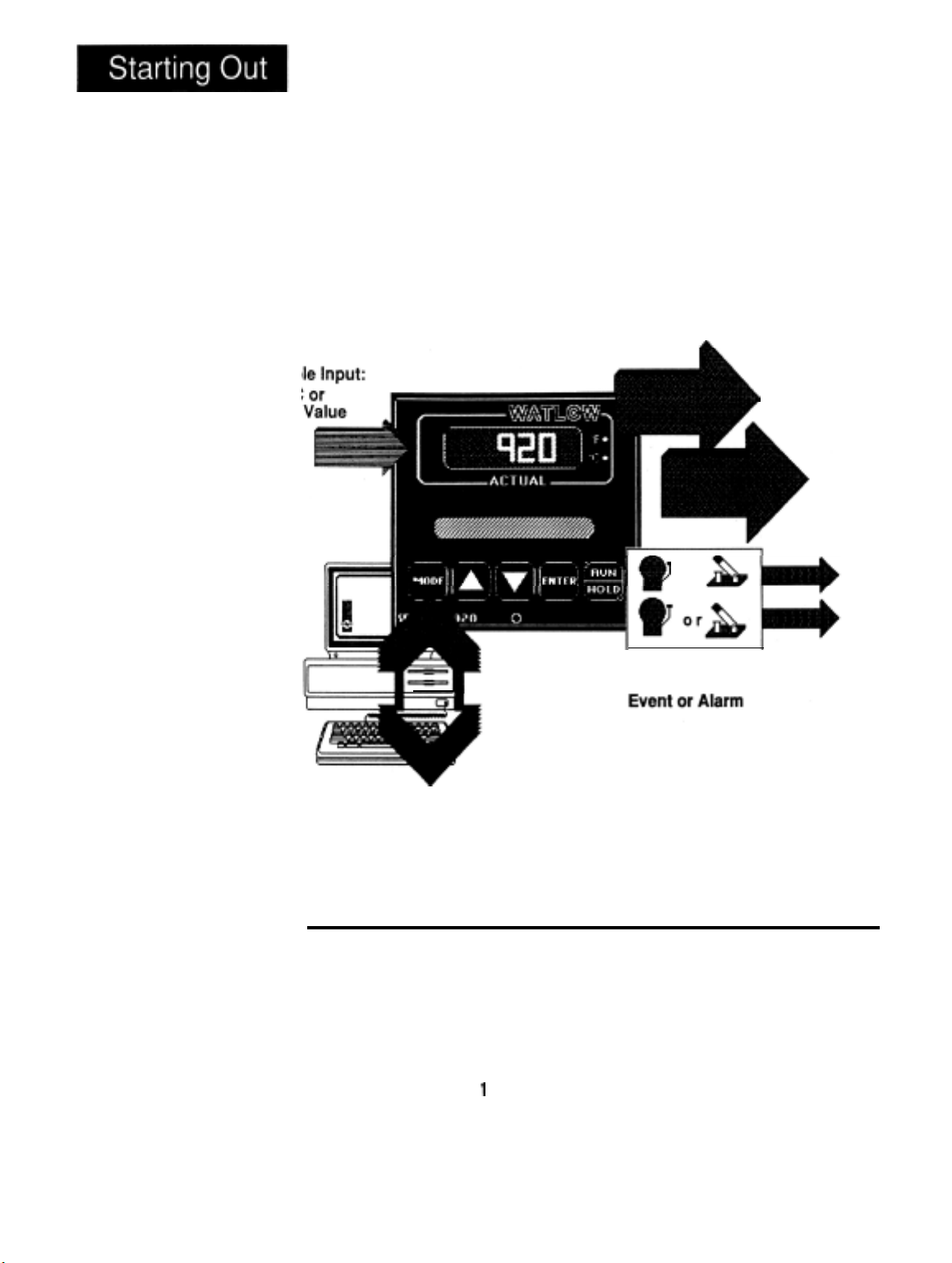
Series 920 Input and Output Overview
How to Open the Series
920
DIP Switch Location and Orientation
Overview
of the Three Operating Modes
Series 920 Front Panel Information
Actual and Alphanumeric Display Front Panel Information
Keyboard Front Panel Information
RUN Key Flow Diagram
Differential Mode Filter Diagram
Common Mode Filter Diagram
Combination Differential-common Mode Filter Diagram
Series 920 Faceplate Dimensions
Series 920 Dimensions (side view)
Series 920 Panel Cutout Dimensions
Series 920 Power Wiring
Input Options Wiring Diagram
Auxiliary Wiring Diagram
Output 1, S.S. Relay, Wiring Diagram
Output 1, S.S. Switch, Wiring Diagram
Output 1,
Output 1,
Output
Mech.
Relay, Wiring Diagram
Triac,
Wiring Diagram
1,4-20mA,
Wiring Diagram
No Output 2
Output 2, S.S. Relay, Wiring Diagram
Output 2, S.S. Switch, Wiring Diagram
Output 2,
Mech. Relay,
Wiring Diagram
System Wiring Example
Guaranteed Soak (GS) Example
SYSTEM Key Flow
SETUP Key Flow
PROGRAM Key Flow
Alarm Type for
Alarm 1
is “process” alarm
Alarm Type for Alarm 1 is a “deviation” alarm
Alarm limits for Alarms 1 and 2 with “process” type alarm
Alarm limits for Alarms 1 and 2 with “deviation” type alarm
J, K, T Reference Compensator to 920 Connection Diagram
“R"
Reference Compensator to 920 Connection Diagram
Decade Resistance Box to Series 920 Connection Diagram
Voltage/Current Source to Series 920 Connection Diagram
Figure 1
Figure 2
Figure 3
Figure 4
Figure 5
Figure 6
Figure 7
Figure 8
Figure 9
Figure 10
Figure 11
Figure 12
Figure 13
Figure 14
Figure 15
Figure 16
Figure 17
Figure 18
Figure 19
Figure 20
Figure 21
Figure 22
Figure 23
Figure
24
Figure 25
Figure 26
Figure 27
Figure 28
Figure 29
Figure 30
Figure 31
Figure 32
Figure 33
Figure 34
Figure 35
Figure 36
Figure 37
Figure 38
Figure 39
9
16
17
17
18
18
22
41
43
50
56
65
53
Contents
DIP Switch Selection
Series 920 Ramp and Soak Program
Editing Your Program, Steps 4-7
Adding the AUTOSTART Step
LlNKing
The
to Another File
WAITFOR
Step
Noise Suppression Device Ratings
SYSTEM Prompts and Description
SETUP Prompts and Description
Table 1
Table 2
Table 3
Table 4
Table 5
Table 6
Table 7
Table 8
Table 9
PROGRAM Prompts and Description Table 10
Operating Band Limits and Ranges
RTD Calibration Settings for
JIS
Master Step Chart
Table 11
Table 12
Chart 1
WATLOW Series
920
User’s
Manual
5
Page 6
Figure
Series
output
l-
920 Input
Overview
Selectab
RTD,
T/C
Process
and
Chapter 1
Starting out with the
Watlow Series 920:
A Microprocessor-Based Control
or
Dual
PID
or
ON/OFF
outputs
FF
Two Auxiliary Outputs
RS-422A
Optional Computer Interface
or
RS-423A (RS-232C
Compatible)
General Description
Congratulations, you’re about to become a fully-qualified user of the Watlow
Series
simple to learn. A ramp progresses from one set point to another set point over a
period of time.
920 and its operation.
Figure 1 is a simplified view of the Series
microprocessor-based, 1/4 DIN-sized ramping temperature control. The 920
accepts a single, front panel-selectable input. This includes Type
or B thermocouple input, a 1° or 0.1°
has a full control temperature range, offset calibration, and a front panel lock-out
feature.
6
WATLOW Series 920
User’s
920!
This versatile microprocessor-based ramping control is powerful, yet
In this chapter of the user’s manual, you’ll get an overview of the
920’s
capabilities. It is a dual output,
J,
K, T, R, S,
RTD
input, or one of two process inputs. It
Starting
Out,
Chapter
Manual
1
Page 7

The Series 920 is a
PID
controller. You may input two complete sets of
PID
parameters on the front panel for heat/cool applications. This includes rate,
reset, proportional band and cycle time. By setting the proportional band(s) to
zero, the Series 920 becomes a simple
ON/OFFcontrol
with a
3°F
or
1.7°C
switching differential.
The 920s auxiliary outputs may be alarms or events. An event is an ON/OFF
auxiliary output relay signal. You can use events, based on time, temperature,
or other process variables, to trigger peripheral equipment or processes.
Operator-friendly features include automatic entry codes or “prompts” to aid in
setup. When there’s a power outage, the Watlow Series 920 stores all information in a non-volatile memory.
When you first apply power, the unit will “come up” with default values for set
points, alarm points and control
parameter.
These default values provide
minimum operating information for the control until you program in the desired
data. The default values are listed in the Master Step Menus and Charts,
pp.
41-50.
Remove the Series 920 carefully from its shipping container. Be sure to set
this literature aside where it will not be discarded.
Packing List
Included with your Watlow Series 920 are two mounting brackets with integral
screws, and this manual.
If your unit has communications, the “How to Use
Data Communications with the Watlow Series 922” manual is also included.
Put Your Control to Work-Three Steps
Once your control is installed and wired, getting the Series 920 “up and run-
ning” is a three-part process:
l
First, match the control’s “personality”, to your system in what we call the
SETUP menu; input type, units of measure, range, calibration offset, output
action, alarm type, lock-out.
l
Second, tune the control making final
l
Third, enter up to ten separate profiles in the PROGRAM menu.
PID
entries.
WATLOW Series 920 User’s Manual
7
Page 8

How to Open the 920
7
0
A
The front panel
screw turns
only. Do not apply
excessive force or
turn the screw more
than
CAUTION:
90°
90°.
Before going further, open the Series
case. Here’s how:
The control chassis fastens to the case with a single screw located on the
lower front panel. See Figure
Three or four strip connector
power and signals through the back of the casing to the triple terminal strip.
These plugs will let go as you pull.
f
l
A
When removing the Series
When returning the control to the case, be sure you have the top up to match
the plugs with the case. The 920 will not fit in to the case upside down. Always check to see that it is oriented correctly.
the front panel screw clockwise to secure it.
2.
plugs, in the rear of
920
control from its case, pull firmly but gently.
920
and pull the control chassis from its
Turn the screw counterclockwise to loosen it.
the control chassis, feed
Press the unit in firmly, then turn
Figure 2
How to Open the
Series 920.
-
How to Set the DIP Switches
The Watlow Series 920 has a Dual In-line Package (DIP) switch inside the
control on circuit board
appear in Figure 3. The switches are clearly numbered from left to right. You
will use DIP switches #1 and 3 - 8; #2 is not used. Table 1 on the next page
shows the DIP switch selections.
AOO7-1699.
The locations of the board and switch
8
WATLOW Series 920 User’s Manual
Starting Out Chapter 1
Page 9
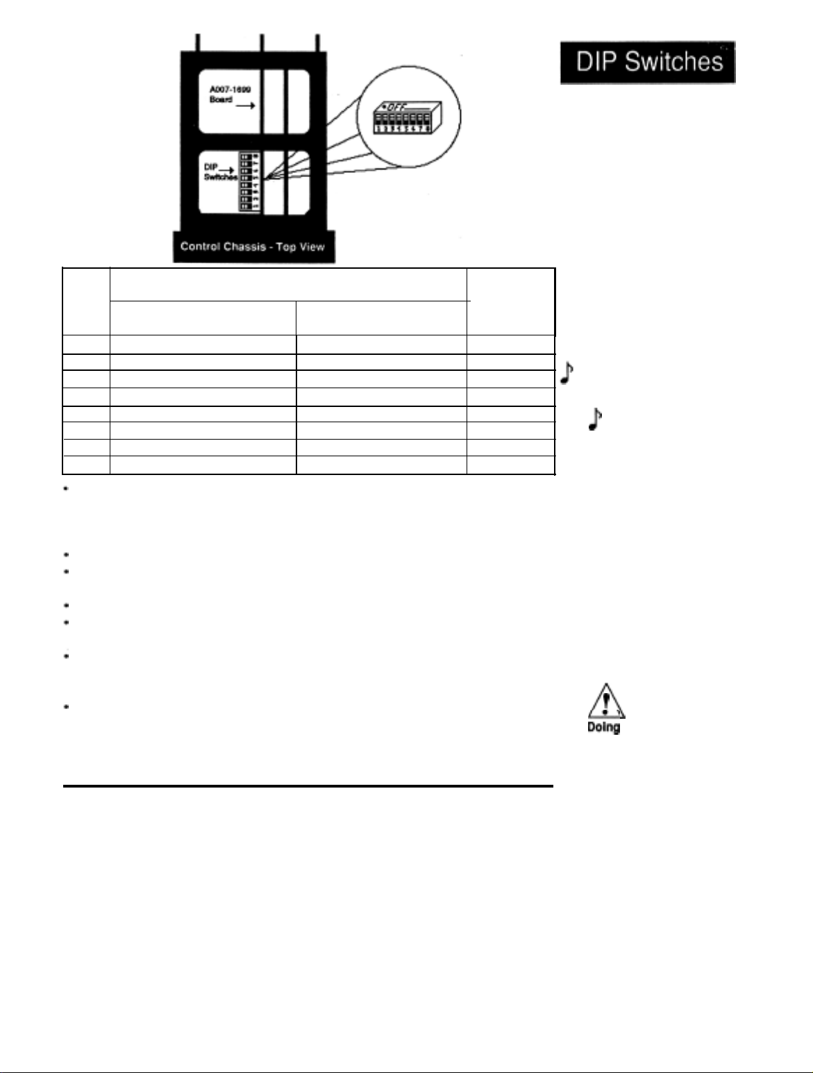
Figure 3
DIP Switch Location
and
-
Orientation.
DIP
SW#
ON
1
2
3
4
5
6
7
8
Cold Start
Not Used
Tenths of units displayed
0-5VDC/0-20mA
Primary output is
LEDs
are load indicators
Selected SPCLFUNC promts
Factory Test/Calibrate
DIP switch #1 determines a warm or cold start. A
grammed information in the 920s memory back-up protection. A “cold” start is a
“clean” startup condition; all user-programmed information is lost. The Series
920 leaves the factory programmed for a warm start.
DIP switch #2 is not used.
DIP switch #3 determines if the decimal point is displayed in tenths of units for
process inputs.
DIP switch #4 is for
DIP switch #5 is for units with
set switch #5 ON for the Primary output.
DIP switch #6 determines the function of the front panel
actual display. When ON, these
or system troubleshooting, see Page 12 and 33.
DIP switch #7 is OFF, all SPCLFUNC prompts are displayed, when ON,
factory selected prompts appear. See Page 42. DIP switch #8 is a factory
calibrate switch.
Function
input
4-20mA
0-5VDC/0-20mA
4-20mA
LEDs
Normal
Operating
OFF
Warm Start
Not Used
No decimal displayed
l-5VDC/4-20mA
Primary output is not 4-20
LEDs
are °F or
All SPCLFUNC prompts
Normal
input or
output.
can be used as a diagnostic tool for tuning
Operation
l-5VDC/4-20mA
input
°C
“warm”
If your unit has
LEDs
Position
OFF
OFF
Choose
Choose
Model #
Choose
Choose
OFF
start saves all pro-
input selection.
4-20mA
to the right of the
Dep,
output,
only
test/
Changing the Position of a Switch
Whenever you change the position of a DIP switch, follow this procedure:
1.
Remove power from the 920. Turn the front panel screw
2.
Grip the front panel bezel and pull it straight out from the control case.
The control chassis will come out of the case as you pull the bezel.
90°counterclockwise.
Table 1
DIP Switch
Selection.
J
For units with
process input only.
If
have process input,
DIP Switch #3
should be in the OFF
position.
n
Dokg
will cause all setup
parameters and files
to be lost. DO NOT
put DIP switch #1 in
the ON position
unless all
programmed
information is to be
cleared.
-
NOTE:
your unit does not
T
WARNING:
a cold start
user-
3.
Set the DIP switch to the position you want.
4.
Return the control chassis to the case. Be sure you have it oriented correctly. It will not fit in upside down, but check just the same. Press
firmly, but gently, to seat the chassis.
Secure the front
5.
Starting
Out,
Chapter 1
panel
screw and re-apply power to the 920.
WATLOW Series 920
User’s Manual
9
Page 10

Overview of the Three Operating Modes
Operating
Before getting into the details of the Series 920s keys and displays, take a look
at Figure 4 showing the three different modes. After you feel comfortable with
the names of the modes and their functions, go ahead to learn the keys and
displays.
Figure
Overview of the
Series 920
O
perating
4
-
Series 920: Three Mode Types
Manually
Control
outputs
Enter
Program
Steps & View
Program
Set Up
Your
System
SYSTEM
PROGRAM
SETUP
SYSTEM
Generates a
ramping set point
(fixed), and can
manipulate events,
clear alarms and
error codes.
Mode
non-
PROGRAM Mode
Enter or view step type,
program loops,
wait for...
points, auxiliary
(event) outputs ON/OFF,
and step duration.
conditions,
set
SETUP Mode
Set up or change
system-operating
parameters such as
real time, high/low
range,
alarm points,
settings, RS-422
address.
alarm
types,
PID
10 WATLOW
Where To Go From Here:..
You are now ready to find out more about the Series 920s keys and displays.
Continue to Chapter 2.
Series
920 User’s Manual
Page 11

Chapter
2
How to Use the Keys and Displays
This chapter will show you the Series 920 front panel, and the function of each
display, key and LED. Figures 6
Display, Key and LED-Location and Explanation
The
Watlow
ACTUAL display at the top of the unit, and the smaller alphanumeric display
below. You set up the Series 920s characteristics in the alphanumeric display
window. On the right of the ACTUAL display there is a red OF LED and a red
°C
LED, indicating the temperature scale ACTUAL is displaying. If neither of
these
Units
The 920 has five touch-membrane keys along the bottom edge of the front
panel: (from left to right) a MODE key, an UP key, a DOWN key, an ENTER
key, and a RUN/HOLD key.
Series 920 Ramping Control has two main displays, the process
LEDs
are showing, the ACTUAL display is showing Process Variable
(PVU’s).
and 7
explain the 920 front panel.
The MODE key steps the processor through the entry prompts.
The UP and DOWN keys increase and decrease or change values in the
alphanumeric display. A single touch to either of these keys will change the
least significant digit by one. Continuous pressure will change the value in the
alphanumeric display at an increased rate. The ENTER key places the value,
in the alphanumeric display, into the processor’s memory.
An alphanumeric display value will flash (when changed with the UP or DOWN
keys) until you press ENTER, placing the value in the processor
The RUN/HOLD key will execute or halt a program.
memory.
Front Panel Information
Use Figures 6 and 7 to assist you in learning the locations and functions of the
front panel components.
How
to Use Keys and Displays, Chapter 2
WATLOW Series 920
User’s
Manual
11
Page 12
Use the following figures to learn the nature and function of the Series 920s
keys and displays.
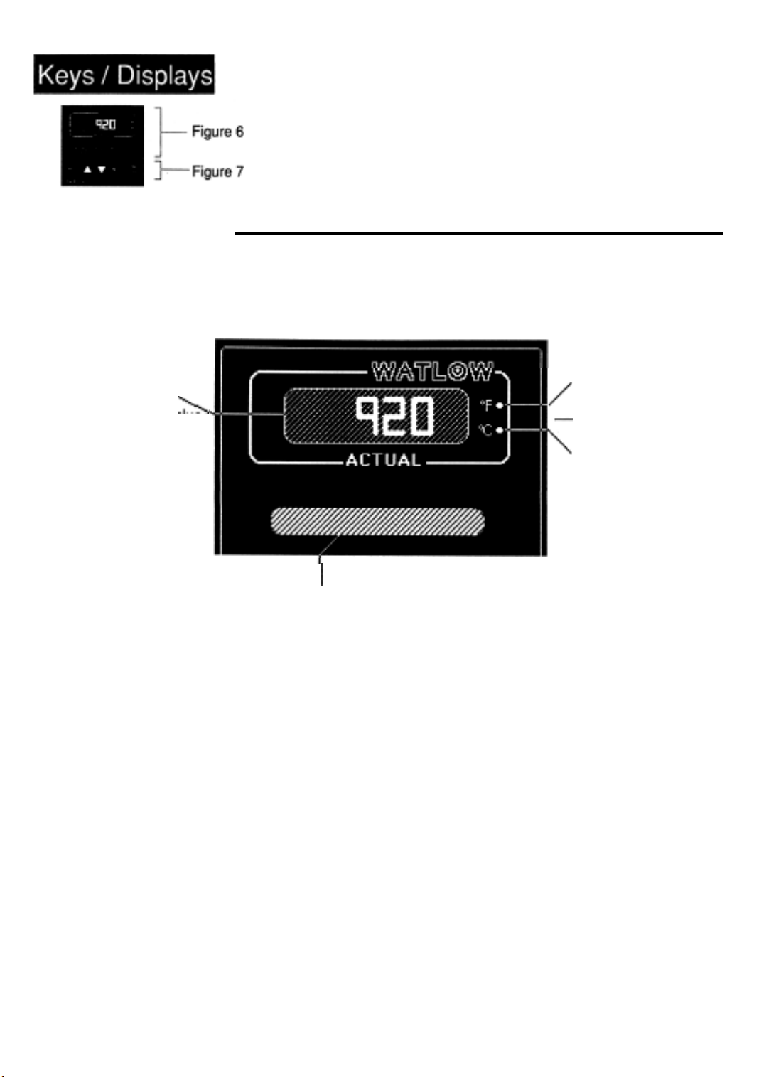
Figure 5
Series 920 Front
Panel Information.
ACTUAL Display
-
X,
Shows the actual value
of the process variable
up to four digits.
Figure 6
Actual and
Alphanumeric
Display
Front Panel
lnformation.
-
Actual and Alphanumeric Display Area
°F
LED
When DIP switch #6 is
OFF, it indicates the value
in the ACTUAL display is
temperature in degrees
Fahrenheit. When DIP
switch #6 is ON, it indicates
Output 1 is energized.
When DIP switch #6 is
OFF, both °F and
LEDs
is displaying Process
Variable Units
°C
LED
When DIP switch #6 is
OFF, it indicates the value
in the ACTUAL display is
I
Alphanumeric Display
Shows entry prompts
and the parameter
values in alphanumerics.
temperature in degrees
Celsius. When DIP switch
#6
is ON, this LED indicates
Output 2 is energized.
°C
are OFF. The 920
(PVUs).
12
WATLOW Series 920
User's
Manual
How to Use Keys
and
Displays, Chapter
2
Page 13
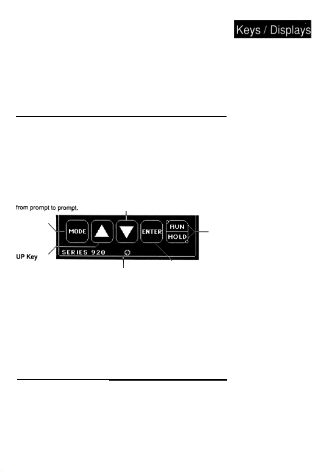
Keyboard Area
MODE Key
This key steps the
Series 920 in sequence
DOWN Key
Acts opposite the UP
key. Decreases the
value in the alphanumeric display. A light
touch decreases the
value by one digit. Hold
the key down to
decrease the displayed
value at a rapid rate.
Figure 7
Keyboard
Panel Information.
Front
RUN/HOLD Key
Executes or holds a
program from the
SYSTEM menu.
Run/Hold
When the HOLD LED is
ON steady, the 920 is in
a HOLD condition.
When the HOLD LED
flashes, the unit is
holding for a
Increases the value
in the alphanumeric
display. A light
touch increases the
value by one digit.
Hold the key down
to increase the
displayed value at
a rapid rate.
I
90°
Front Panel Screw
Secures the control
chassis in its case with
a
1/4
turn clockwise or
releases the chassis
with a
1/4
turn counter-
clockwise.
ENTER Key
Enters selected
(flashing) data into
the microprocessor
memory, or will mask
an error code or
latched alarm for
1
minute.
condition, or a guaranteed soak condition.
When the RUN LED is
ON the 920 is in the
RUN condition.
Where To Go From Here
Now that you have a good idea where everything is on the faceplate of the
Series 920, continue to Chapter 3 for the Sample Program. If you skip the
sample program, do not forget to check the position of DIP switch #1 before
you begin programming your control after installation. With DIP switch #1
OFF, the 920 saves your program whenever power is removed (warm start).
With DIP switch #1 ON, the 920 will clear its memory of all programmed
information whenever power is removed, substituting default values (cold
start).
How to Use Keys and Displays, Chapter
2
WATLOW Series 920 User’s Manual
LEDs
WAITFOR
13
Page 14

Chapter
3
m
WARNING:
Doing a cold start
will cause all setup
parameters and files
to be lost. DO NOT
put DIP switch #1 in
the ON position
unless all
programmed
information is to be
cleared.
user-
Learning
the Series 920
-
A Sample Program in Action
This chapter
can quickly grasp the necessary terms and concepts by entering and
exercise.
If you feel that your
program to learn the Series 920, skip this chapter.
A Brief Overview
This sample program wilt teach you the fundamentals of creating a ramping profile,
along with ways to expand that profile to its greatest versatility.
The program example will start with a simple ramp and soak profile. A ramp progresses from one set point to another set point over a period of time, or ramp rate,
expressed in degrees/time. Soaking then controls the length of time the temperature
is held at this level.
We will, then expand it to
form an AUTOSTART, LINK to another profile, and finally perform a
At this point make copies of your Master Step Chart on Page 53.
to keep track of your program as you go.
exactly what you want your program to do.
will
guide you through an easy sample program for the Series 920. You
knowledge
multiple
observing
of profiling controllers does not require a sample
ramp and soaks, add
It is also a good idea to sit down and define
JUMPLOOP
functions, per-
It is a good practice
WAITFOR
this
step.
14
WATLOW
Enter Real Time of Day
First, set the Series 920s “real time-of-day,
key is used to progress through the menus. The UP/DOWN keys are used to select
parameters and values, and remain flashing until you press the ENTER key.
Press the MODE key until the SETUP menu appears. Press the ENTER key.
1.
2.
At ACCESS, enter (0) with the UP/DOWN keys; press ENTER. This is your
Series
calibration
3.
Press the MODE key until HOUR appears in the alphanumeric display and press
ENTER. Note that hours are in a 24 hour format.
920 User’s
Manual
(CALIB)
menu.
24-hour
clock.” Remember the MODE
Sample
Program, Chapter
3
Page 15

2
4.
Use the UP/DOWN keys to place hours into the display. The display will flash
until you press ENTER.
5.
J
Press MODE to continue to the
rect value for minutes and press ENTER.
6.
Press the MODE key several times to return to the top of the ACCESS (0) menu.
At the top of the ACCESS (0), which is the
Time (Tl) displayed.
7.
Continue to press MODE until
SYSTEM.
Before Entering Your Program
Before we begin to program your Series
parameters to enter. Verify that DIP switch #7 is OFF. If you have not tried any
programming since your cold start, the C/F/U (Celsius/Fahrenheit/Units) and GS
(Guaranteed Soak) parameters are set to their appropriate values.
sary for a more detailed definition.
parameters and entering values, it might be a
to see that the values are correct.
1.
Press the MODE key until SETUP appears. Press ENTER. Once again you see
the ACCESS parameter. Use the UP/DOWN keys to enter (5) and press ENTER;
this is the Special Function (SPCLFUNC) menu.
MIN
parameter and press ENTER.
CALIB
menu, you
you
reach RETURN. Press ENTER to return to
Enter the cor-
will
see the Real
a
920,
there are a few other initial SETUP
Refer to the glos-
If you have already tried stepping through the
good
idea to go back and double check
J
NOTE:
When either the
hours or minutes are
entered,
seconds are set to 0.
J3
DIP switch #7 must
be OFF to access all
SPCLFUNC
ters.
internal
NOTE:
parame-
2.
Press MODE again until you see the C/F/U parameter. This parameter will defautt
to F. Use the UP/DOWN keys to enter degrees F (Fahrenheit). Press ENTER..
3.
Continue through the SPCLFUNC menu
Enter a value of (0); press ENTER. This parameter has a default of 0.
4.
Press the MODE key to move to the RETURN parameter. Press ENTER to return
to SYSTEM.
5.
Good job! You have completed the initial setup, and are ready to program the 920.
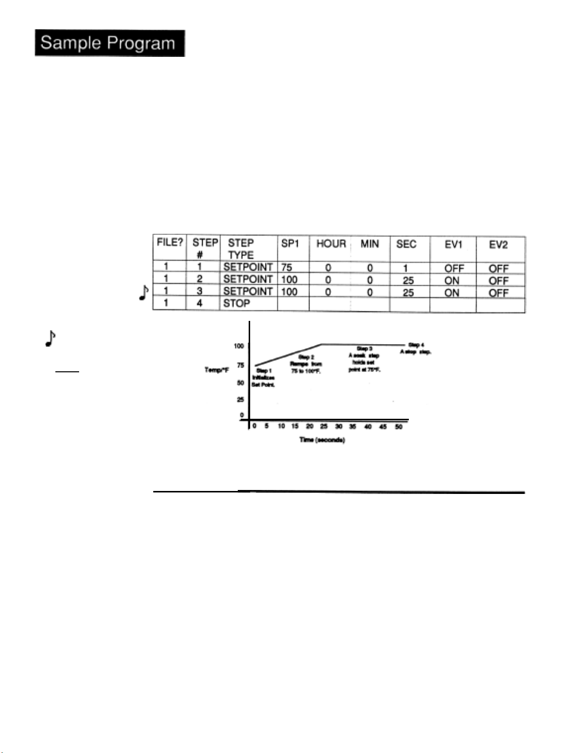
Programming. File
Our first step in programming will be to make a short ramp and soak program. Step
initializes the set point to a known starting point for the ramp, Step 2 is a short ramp,
Step 3 is a soak step, which holds the programmed set point constant for the pro-
grammed time.
1.
From the SYSTEM menu, press MODE until you see the PROGRAM menu.
Press ENTER.
2.
The Series 920 asks you for a FILE?. Your 920 should already say (I), but if you
have entered any values, it may be different. Make sure it says (1). Press ENTER.
Step 4 will be a STOP step which signals the end of a file.
1
until you see GS
(Guaranteed Soak).
1
3.
Press the MODE key and you are asked for a STEP. ENTER (1) if it is not already
there.
Sample Program, Chapter 3
WATLOW Series 920 User’s Manual
15
Page 16
Press the MODE key. Use the UP/DOWN keys to select the step type and
4.
values.
Use Table 2 to enter the corresponding parameters and values. The parameters
5.
appear from
progress through the menus. After the step # is selected, use the UP/DOWN
keys to select a step type. Press ENTER. Use the UP/DOWN keys to select
parameters and values, they remain flashing until you press the ENTER key.
At the end of each menu, rather than pressing ENTER to go back to SYSTEM, press
MODE for the STEP prompt. The 920 automatically increments to the next step
number, with the step number flashing. Press ENTER.
left
to right on the table.
Remember that the MODE key is used to
Table 2
Series 920
Ramp and Soak
Program.
J
Step 4 must be
entered
even though it
defaults to a STOP
step.
-
NOTE:
as a step
125
Running Your Program
1.
Return to SYSTEM using the ENTER key at the RETURN prompt.
RUN/HOLD key.
Press
the
16
2.
The Series 920 now asks you what
not already entered.
Press the MODE
3.
Again, press (1) if it is not already there, and press ENTER.
The Series 920
LED is now lit. After each step is completed, the next step that the Series 920
performs will appear.
You may step through the parameters to see what the step-type is and what the
parameters are set at. The Time Remaining is also displayed at the end of the menu.
Once the Time Remaining reaches 00:00:00, it will show you what step it has progressed to. Refer to the Run menu on Page
WATLOW Series 920 User's Manual
quickly
FlLE?
you would like to run. Enter (1) if it is
key. The 920 asks you what step you would like to start on.
shows you the SP (Set Point) and jumps to Step 1. The
19.
Sample Program, Chapter 3
RUN
Page 17
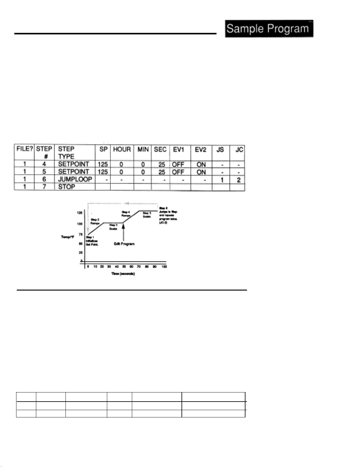
Editing Your Program
Let’s try editing the program by expanding it with another ramp and soak step and
adding a jump loop. We’ll jump to Step 1 and repeat Steps 1 - 6 two more times. This
is accomplished by programming a Jump Step (JS) = 1 and Jump Count (JC) = 2.
When your 920 goes through the program and reaches Step 6, it jumps back to Step
and repeats the program two more times.
By this time you should understand the basic concept of the Series 920 and be able to
get around on your own. Remember that the MODE key takes you through the menus.
Use the UP/DOWN keys to select parameters and values, and press ENTER.
1.
Return to the PROGRAM menu.
2.
Enter FILE?
step to a
(1),
Step (4). We are going to change this step type from a STOP
SETPOINT
step. This will be our second ramp. Use Table 3 to enter
values into the corresponding parameters.
3.
Once you have edited your program, run it again and watch its progress.
1
Table 3 Editing
Program,
Steps 4-7.
Your
1
Adding an AUTOSTART Step Type
The Series 920 can also automatically start your program, or a step, on a specified
day and time. When you use AUTOSTART, it stops your program, and waits for the
day and time you entered under the AUTOSTART step type. The Series 920 then
executes the next sequential step. AUTOSTART allows you to wait up to seven days
in the future; day 0 is always the current day.
1 every time the Real Time clock goes from 2359 to
DAY, and the Real Time clock is greater than the programmed AUTOSTART time,
the AUTOSTART waits 6 days along with the programmed time. If day is left blank,
the program begins each day at the real time programmed, regardless of the day.
Go to the PROGRAM menu.
Edit Step 7 from a STOP step to an AUTOSTART step.
Follow the table below for input values. This step will wait for approximately five
minutes in the future.
The
days accumulated increases by
0O:OO.
If 0 is programmed for
FILE
1
1
STEP#
7
8
STEP TYPE DAY
AUTOSTART 0
STOP
HOUR
Current Hours
MIN
Current Minutes +
5
Run this file starting at Step 7 and observe. The Series 920 will now wait until the
real time of day matches the programmed value.
Sample Program, Chapter 3
WATLOW Series 920 User’s Manual
Table 4
Adding the
AUTOSTART Step.
-
17
Page 18
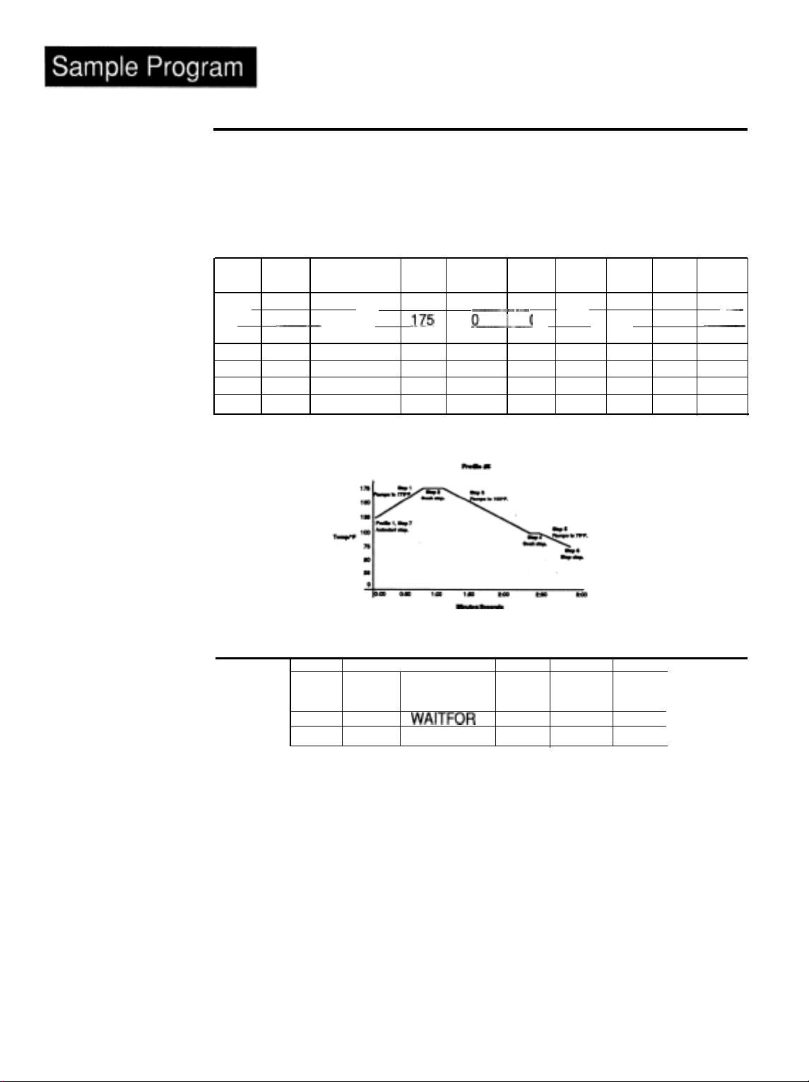
LlNKing
Files
Table 5
LlNKing
Another File.
-
to
The Series 920 enables you to link
files
together. The LINK step allows you to link the
last step of a profile to the first step of another profile.
Lets edit the program again by adding a LINK step at the end of the profile. But first,
lets create another file.
you’ll receive
ER2
If you run your program with a LINK going to a
non-existing
file,
0036, the “no file found“ error. Follow Table 5 to add a LINK and a
new FILE to your program.
FILE? STEP STEP SP HOUR
#
TYPE
1
5
5 2
5. 3
5 4
5
5
8
1
--_-
5
6
LINK .._
SETPOINT
SETPOINT
SETPOINT
SETPOINT
SETPOINT
STOP
_I75
175 0
100 0
100 0
75 0
----_
&___-._.
MIN
SEC
0
.
0
1
0
0
50..
20
15
10
25
EVl
EV2 FILE?
ON ON
ON ON
ON OFF
ON OFF
OFF OFF
_~
5
..~--
Run your program again beginning at FILE 1, STEP 8. Step through the menu to see
the step type you’re on, and time remaining. See what happens at the end of File
1.
Table 6
The
WAITFOR
18
Step.
WATLOW Series 920 User’s
The
WAITFOR
FILE STEP
The last step type we will work with is the
Step
5 6
5 7
#
STEP
NPE
WAITFOR
STOP
WPV
WHR
75
WAITFOR
step. This is a test step.
WMN
-
It compares a specified temperature with the process temperature, before continuing the
program.
It also waits for programmed time to elapse before continuing with the pro-
gram. After the test is successful, the program continues to the next sequential step.
Return to PROGRAM and enter FILE? (5). Add a
WHR and WMN are unprogrammed. To program a
for WHR and WMN. The programmed
WAITFOR
taneously. Once a
process variable (WPV), and time
WAITFOR
condition is satisfied, it won’t have to be performed again.
WAITFOR
WAITFOR
WAITFOR
step to the end of that file.
time, enter your values
time waits that time duration. Both
(WHR,WMN)
can be programmed simul-
Run your program from FILE 5, STEP 1. If you don’t want to go through the entire
program, START your program at any STEP in FILE 1 or 5. When the program reaches
FILE 5, STEP 6, the HOLD LED begins flashing. This means the program is still
running, but is
HOLDing,
Manual
to
WAITFOR
the ACTUAL temperature to equal the
Sample Proqram Chapter
3
Page 19
WAITFOR
Your program then continues to the last step, a STOP step, and HOLD
To change a programmed step, return to the PROGRAM menu, and enter the FILE
and STEP number to change.
and press ENTER. Under a step type, to clear all parameters of the current values,
return to that step type and press ENTER. All parameters will return to
Process Variable
(WPV).
When equal, the HOLD LED stops flashing.
S
again.
Use the UP/DOWN keys to select another step type
their
defaults.
Running Your Series 920
To run the Series 920, you must be at one of the three main level operating parameter
menus, SYSTEM, PROGRAM, or SETUP. Press the RUN/HOLD key. The Series 920
asks you what file
the file and step number, the program begins and the RUN LED is lit. While in the
RUN mode, you can only view the current file and step.
you’d like
to run, and asks what step to begin with. After entering
To change your program, you must be in the HOLD mode. To
any time, press HOLD. When returning to your program, the Series 920 asks if
like to
been changed, generates an
the START prompt and begin the program again.
When in the PROGRAM menu, SP is programmed to the steps ending set point.
When in
the
RESUME? on the step you left off on. Trying to RESUME on a file that has
“ER2
0040”; this is a “Change File Error.” Advance to
the
RUN mode it shows the current set point. In the RUN mode, SE
steps ending set point. Refer to Pages 51 - 52 for definitions of other prompts.
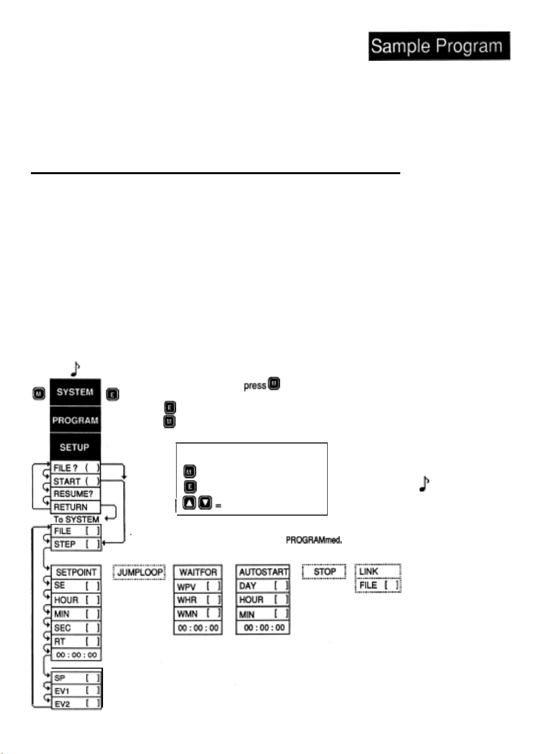
At the SYSTEM prompt,
Press @ to enter the PROGRAM parameter values, or
press @ to continue to SETUP.
Graphics Key
@B
83
1 aa=
One of the three step types will be displayed
J
JUMPLOOP, STOP, and LINK step types are immediate, and will not be visible.
depending on the type of step
=
=
pressm
MODE Key
ENTER Key
UP/DOWN
stop your
program
at
you’d
shows
to continue to PROGRAM mode.
PROGFMMmed.
Figure 8
RUN Key Flow
Diagram.
1
Shaded parameters
may not
your control.
parameters are
dependent on how
your control is
configured. See
Chapter 6
information.
-
NOTE:
appear on
for
These
more
Sample Program, Chapter 3
WATLOW
Series 920 User’s
ManuaI
19
Page 20

Chapter 4
How to Install and Wire the Series 920
This chapter tells you how to install the Series 920.
information is right here.
“burned in” before leaving the factory, the Series 920 is ready to install when you
receive it.
But before you begin working or cutting holes in
chapter to gain an understanding of the entire installation. Consider sensor
installation carefully. You’ll need to look at the noise reduction guidelines before
making your panel cutout.
Because
Watlow
controls are thoroughly tested, and
All
mounting and wiring
panels,
read through this
Sensor Installation Guidelines
We suggest that you mount the sensor at a location in your process or system
where it reads an average temperature. Put the sensor as near as Possible to
the material or space that you want to control. Air flow past this sensor should be
moderate. The sensor should be thermally insulated from the sensor mounting.
Excessive lead length
combat this, use a three wire sensor in long lead applications.
in a two-wire
RTD
sensor can create indication
errors.
To
Input Power Wiring
Microprocessors are in a way
like trout...
20
WATLOW Series
They require a clean environment to be successful and to prosper. A clean
environment means on one level an environment that is free of excessive dust,
moisture and other airborne pollutants. But primarily it means a “clean” source
of input power from which to base all its operations. What is “clean power”?
Clean power is simply a steady, noise-free line voltage source that
rating specifications of the hardware using it. Wiihout clean power to the
integrated circuitry, any microprocessor chip
Just as the water you get from a tap nowadays may not be
in some locales, so the line voltage coming into your facility may not be acceptable for your microprocessor devices. You may have to fitter or “clean” the
water or the power. In industrial environments, the potential for pollutants
increases, especially electrical noise due to high level power
occurring in one place.
The recommendations we are providing for you are ways to achieve a minimum
level of clean input power protection.
remove the potential for input power problems.
ures and still do not get results, please feel free to call us at the factory. We
are here to see that our control products work well and do the job they were
designed to do.
920 User’s Manual
In almost all cases these
isdoomed
If you’ve applied these meas-
to failure.
acceptable
HoHow w to Install and Wire, Chapter 4
How to Install and Wire, Chapter 4
meets
to drink
consumption
guidelines
the
Page 21

Definitions
Ground Loop - A condition created when two or more paths for electricity are
created in a ground line, or when one or more paths are created in a shield.
Earth Ground - The starting point for safety and computer grounds.
a copper rod driven into the earth.
Safety Ground - A ground line run with electrical power wiring to protect personnel.
Computer Ground
or microprocessor-based systems. This line is isolated from safety ground.
Common Mode Line Filter - A
power
line legs with respect to ground.
Differential Mode Line Filter - A device to filter noise signals present
between the two power lines themselves.
The D
Do
interference pick up.
Do use twisted pair wire and possibly shielded wire from line filters to the control to
keep the line “clean”.
Do keep low power control wires physically separated as far as possible from line
voltage wires. Also keep all controller wiring separate from other nearby wiring.
Physical separation is extremely effective. A 12 inch
usually effective.
OS
and
keep line filters as close to the control as possible to minimize the area for
-
A ground line for the ground connections to computers
device
to filter noise signals present on both
Don’ts
of Clean Input Power
(304.8mm)
It is usually
minimum separation is
Do use common mode, differential mode or a combination of the two filters
wherever power may have electrical interferences.
Do cross other wiring at
Do have a computer ground line separate from all other ground lines. This computer
ground line should terminate at the ground rod where the electrical service is grounded.
Don’t connect computer ground to safety ground or any other ground points in
the electrical system, except at the ground rod.
Don’t
mount relays or switching devices close to a microprocessor control.
Don’t run wires carrying line voltage with signal wires (sensor, communications or
other low power lines) going to the control.
Don’t use conduit for computer ground.
Don’t
have phase angle-fired devices in the same electrical enclosure or on the
same power line with the control.
Don’t
connect ground to the control case if the control is mounted in a grounded
enclosure (prevent ground loops).
Don’t fasten common mode line filters or filters with metal cases to metal that is at
ground potential. This prevents ground loops and maintains filter
How to Install and Wire, Chapter 4
90°
angles whenever crossing lines is unavoidable.
effectiveness.
WATLOW Series
920 User's
Manual
21
Page 22

How to Check for Ground Loops
To check for ground loops, disconnect the ground wire at the ground termination. Measure the resistance from the wire to the point where it was
The ohmmeter should read a high ohm value. If you have a low ohm value
across this gap, that means there is at least one ground loop present in your
system.
connected-
Table 7
Noise
Device Ratings.
-
Suppression
Also, check for continuity; your reading should be “open”.
If you do find conti-
nuity, you must now begin looking for the ground loops. Begin disconnecting
grounds in the system one at a time, checking for continuity after each disconnection. When continuity reads “open” you have eliminated the ground loop(s).
Also as you reconnect grounds, keep making the continuity test. It is possible
to reconnect a ground loop.
Noise Suppression Devices
Available from Watlow
Watlow Controls stocks a few key noise suppression parts. You may order
these by calling your local Watlow distributor.
Item
Common Mode Line Filter
Metal
Oxide
Varistor
MOV
I
MOV
MOV
Electrical
250V,
15OV,
130V,
I
275V,
275V,
Ratings
3 Amp
80
Joule
38 Joule
75 Joule
140 Joule
Part Number
0804-0196-0000
0802-0273-0000
1 0802-0304-0000 1
0802-0266-0000
0802-0405-0000
J
NOTE:
For
very
“dirty” or
critical
use micro-computer-regulated
power
Uninterruptable
Power Supply
(U.P.S.)
22
applications,
supply
of
WATLOW
Line Filtering Configurations For Controls
These three diagrams show you filter configurations for removing input power
noise. Choose the one best suited for your system if you are unsure which one
to use.
920 User's
j
Series Manual
Maual
Page 23
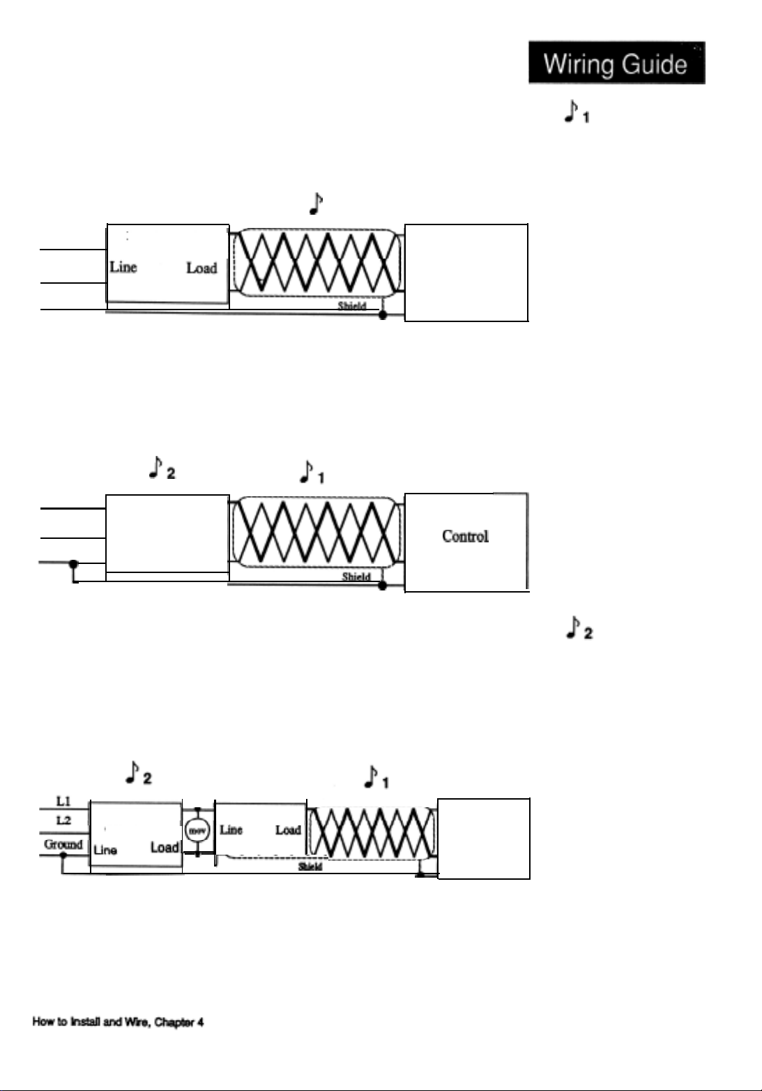
Ll
L2
Ground
D.M. Line Filter
Keep filters
inches
12
(304.8mm)
or
less from the
control. Minimize
the line distance
J
1
where noise can be
w-introduced to the
control.
Control
Figure 9
Differential Mode
Filter Diagram.
-
Ll
L2
Ground
C.M.
Line
Line
C.M.Line Filter
Filter
Load
- 1
rL-___L:_k_-&~
D.M.
Line
Filter
Control
Control
Figure I0
-
Common Mode
Filter Diagram.
To
prevent
ground
loops, do not fasten
common mode line
filters or filters with
metal cases to metal
that is at ground
potential. Doing so
will reduce filter
effectiveness.
Figure 11
-
Combination
Differential-Common
Mode Filter Diagram.
WATLOW
Series
920 User’s
Manual 23
Page 24
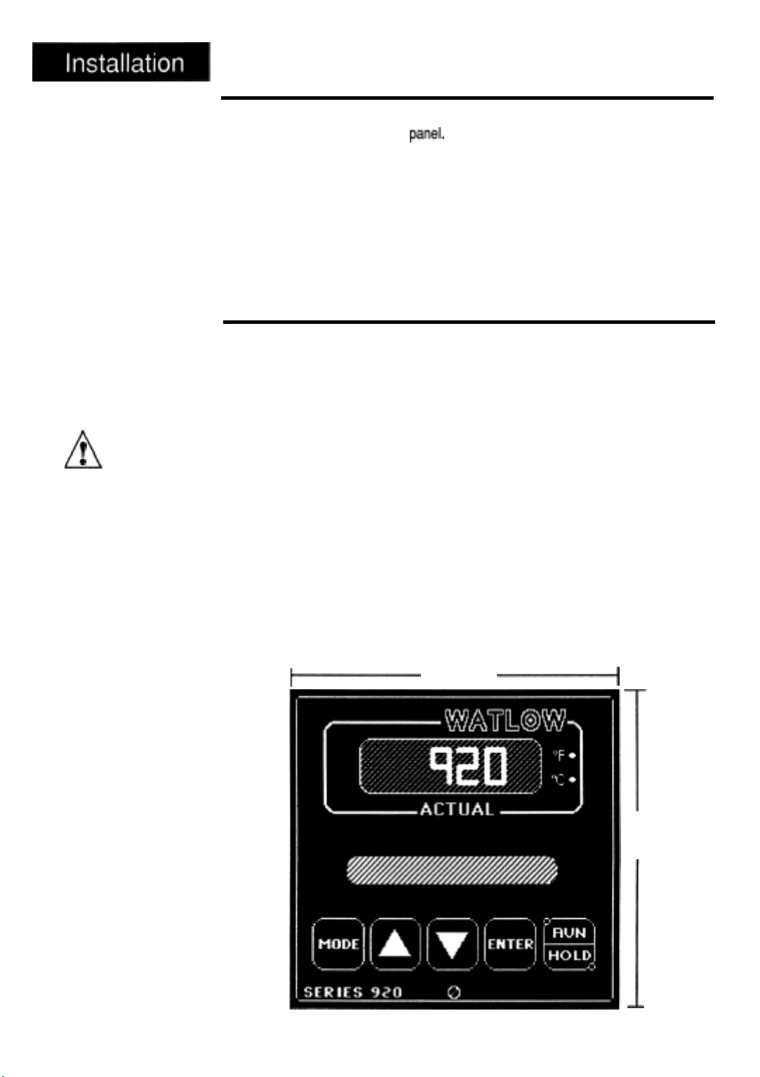
Installation Information
T
0
n
The front panel
screw turns
only. Do not apply
excessive force or
turn the screw more
than
CAUTION:
90°
90°.
The Series 920 mounts in a
hold
the case against
are 3.56 in.
deep.If your unit has a
Figure 12 shows the dimensions of the front
lbs. (1.25Kg).
For unit dimensional and mounting information, including the location of mounting brackets and size of the front
panel’s thickness can be from 0.06
(90.42mm)
panel
cutout with two brackets. These brackets
the
front
panel.
The Series 920 behind-panel dimensions
high by 3.56 in.
triac
output, add another 2.5 in
(90.42mm)
panel
cutout, see Figures 13 and 14. Your
(1.5mm)
wide by 6.0 in.
panel bezel.
to 0.25 in.
(152.4mm)
(63.5mm)
The 920 weighs 2.75
(6.3mm).
to the depth.
Installation Procedure
Follow
this procedure to mount the
1.
Make a
2.
Remove the 920 from its case by turning the front
clockwise
the case.
3.
Place the case in
4.
Attach the mounting brackets either to the top and bottom, or to both sides
of the unit.
5.
Tighten the mounting brackets securely against your panel.
panel
cutout per the dimensions in Figure 14.
(CCW).
Grip the bezel
the
cutout you just made.
Watlow
firmly
Series 920 Temperature Control:
panel
and
screw
pull
the control chassis out of
90°
counter-
Figure 12
Series 920 Faceplate
Dimensions.
-
6.
Insert the
the front
hardware installation is complete. Go on to the wiring section from here.
1~
control
panel
chassis into its case and press the bezel to seat it. Turn
screw
90°
clockwise (CW) to
3.81 Sq.
(96.77mm) ‘-1
lock
the control in place. The
1
3.81 Sq.
(96.77mm)
I
24
WATLOW
Series
920
User’s
Manual
How to
Install
and Wire, Chapter 4
Page 25

(23.37mm)
1
&-Bezel
3.56 ±
0.015
(90.42mm
3 ±0.381
t
3.81
(96.77mm)
Your Panel
Thickness
0.06 to 0.25
(1.524 to
Mounting
6.35mm)
Bracket
3.622 to 3.653
(92.00 to
Panel
cutout
3.625 x 3.625
(92.08 x
Nominal
92.79mm)
92.08mm)
3.622 to 3.653
(92.00 to
I
92.79mm)
How to Wire the Series 920
This section has all the information you need to
the Series 920 and your system. Please read the Safety Information in the
narrow column on the outside of each page. You will find internal circuits on
the left in the following diagrams, and external circuits on the right.
output options are listed by model number. Refer to the unit sticker on your
control to be sure that you are wiring from the corresponding diagram. We
suggest that you read through the entire section
Then proceed, starting with the sensor inputs, auxiliary outputs, then control
outputs, data communications, and finally, power wiring.
complete
before
a good wiring job on
beginning your hookup.
In addition,
0
It is very important to enter a system set point in the Series 920 before
power to the load circuitry.
applying
Figure 13
Series 920
Dimensions.
(side
Figure 14
Series 920
Panel Cutout
Dimensions.
0
To
shock, make all
connections on the
back
before
power to the control.
Also, disconnect
power before
opening
920.
load power to the
output circuits until
you have entered a
system set
-
view)
-
WARNING:
avoid electric
of the control
connecting
the
Series
Do not apply
point
l
In all wiring diagrams, internal circuits are on the left and external
circuits
How to Install and Wire, Chapter 4
are on the right.
WATLOW Series 920 User's Manual
25
Page 26

1
0
To
electric shock, use
National Electric
Code safety practices when wiring
and connecting this
source and to
WARNING:
avoid potential
unit to a power
electrical sensors or
peripheral devices.
Power Wiring
01
1
NOTE:
For
jumper 18
230VAC,
@2
to
19
0;
J3
A
NOTE:
For
jumper 17 to 19
and jumper l8 to 20
115VAC,
0
2 WARNING:
To avoid electric
shock, connect the
chassis ground
terminal to “Earth
Ground.”
Figure 15
Series 920 Power
Wiring.
n
Remove the short
green ground
jumper on the back
of the 920
your control is
mounted in a metal
panel connected to
safety (chassis)
ground. Removing
the jumper will
prevent ground
loops. OR
Leave the short
green ground
jumper in place if
the Series 920 case
is not connected to
safety (chassis)
ground.
?
0
-
CAUTION:
(T-21)
if
Chassis
GND
Green
GND
k
Wire
0
Disconnecting the green ground jumper
present on the metal case.
Connect the AC power lines and the jumper wires to the power supply terminal
strip of the Series 920. Study the strip connections carefully before beginning.
Be sure to use these jumpers on the power supply
jumper 18 to 19. For
All wiring and fusing should conform to the National Electric Code and to any
locally applicable codes also.
When you apply power without sensor inputs on the Signal Conditioner termi-
nal strip, the Series 920 alternately flashes from SYSTEM to
is an error code indicating an open sensor. These are
unit without sensors.
Before applying power, open the Series 920 and set DIP Switch #1 “ON” for a
Cold Start.
the unit. (This clears all previously entered information from the 920; it is a
“clean” or “cold” start.)
Now remove power again, open the unit, and set the Switch #1 to OFF, (This
will make the next
information in the processor’s memory.) Close the 920.
3 WARNING:
Replace the control chassis in the enclosure and apply power to
start
Ll
Ground
wire
could allow A.C. voltages to be
115VAC,
jumper 17 to 19 and jumper 18 to 20.
a “warm” one, retaining all subsequently entered
17
18
19
20
terminal
normal
strip.
ERl
displays for a
Ll
Ground
For
230VAC,
00XX. This
26
WATLOW Series 920 User's Manual
How to Install and Wire, Chapter 4
Page 27

Input Options: Terminals 1 - 8 Apply One Input Only
RTD
k
l For
RTD
input, use
Terminals 1,2
and 3.
1
NOTE:
For a
two-wire
use Terminals 1 and
2 for the RTD, and
jumper Terminal 2 to
Terminal 3.
RTD,
l For
0-5VDC, 0-20mA
or
1-5VDC, 4-20mA
input, use Terminals
4 and 5.
l
T.C. Compensation
For T/C input, use
Terminals 6 and 8.
Front-Panel Input Selection Also Required
Auxiliary Output: Terminals 9 - 13
Figure 16
input Options
Wiring Diagram.
See model number
information, p. 61,
for the input option
that applies to your
unit.
Figure 17
Auxiliary Wiring
Diagram.
See model number
information, p. 61,
for the alarm output
option that applies
to your unit.
-
-
Terminals 9 & 10
are Auxiliary Output
1
NOTE:
Auxiliary outputs go to a de-energized
state when in an
How to Install and Wire, Chapter 4
alarm
condition.
WATLOW Series 920 User's Manual
#2.
12, & 13 are
iary
NOTE:
Terminals 11,
Auxil-
Output
#1.
27
Page 28

Output #1 Option B, Terminals 22 - 24
Figure 18
Output 1, S.S. Relay,
Option "B", Wiring
-
Diagram.
Figure 19
-
Output 1
S.S. Switch,
Option
Wiring Diagram
"C",
Model#92OA-_
i
!
S.S.
B _
m
,
m
I
I
m
I
m
k
I
_-_000
output
#1 to
Load from
S.S. Relay,
23 N.O.
(MT2)
0.5A
Output #1 Option C, Terminals 22 - 24
Model #92OA-_
C _ _-_000
28
WATLOW Series 920 User’s
Manual
Output
Load from
S.S. Switch, 20mA
22
Switched DC (open
23
+
Unreg.
#1 to
collector)
(20VDC @ 20mA
max.)
-
Switched
+ 3-32VDC
Solid State
Page 29

Output #1 Option D, Terminals 22 - 24
Model #92OA-_
D_ _-_000
Output #1 to
Load
from
6A SPDT Relay
;~~~~~~~~~~~~_~_~_______,
i
Mechanical
:
Relay
:t
:
:
I
:
:
I.1
II
l+
I
:
:
I
:
Output #1 Option E, Terminals 22 - 24
m
/?\
Figure 20
Output 1
Relay,
Wiring Diagram.
A
n
L2
If you use normally
closed
Ll
the mechanical
relay, you may need
to add an external
snubber (Watlow
Part #
0000) across the
normally closed
contacts to avoid
Option "D",
T
0
CAUTION:
contacts
0804-0147-
-
Mech.
of
RF
noise and potential
malfunction.
mally
open contacts
are
protected
internally.
Nor-
Model #92OA-_
E_
_-_000
Back of the control
15ATriac
Figure 21Output 1, Trlac,
Option “E",
Wiring Diagram.
j
NOTE:
Terminal #24
not
have load wires
connected to it. It is
used
only
for the
gate of the
L2
located
on the back
of the control.
should
triac
How
to Install and Wire,
Chapter
4
WATLOW
Series 920
User's Manual 29
Page 30

1
NOTE:
Current for the
4-20mA
sourced
the control.
Use ungrounded
sensors only.
Figure 22
output
Option
Wiring Diagram.
loop
is
internal to
1,4-20mA
"F",
Output, #l
Option F, Terminals 22 - 24
Model #920A-_
F _ _-_000
Output #1 to
Load from
4-20mA
1
24
source
mA
Figure 23
No Output 2.
Figure 24
output 2
Option
Diagram.
-
-
S.S. Relay,
"B",
Wiring
Output #2 Option A, Terminals 14 -
Model #92OA-
--
A_-_000
14 Not Used
16 Not Used
16
Output #2 Option B, Terminals 14 - 16
Model #920A-
--
B_-_000
Output
Load from
S.S.
Relay,
#2 to
0.5A
30
WATLOW Series 920 User’s
Manual How to Install and Wire, Chapter 4
D
I
m
I
I
D
14 N.O.
(MT2)
16 COM (MT1)
LOT+*
I
_
L2
l
L1
Page 31

Output #2 Option C, Terminals 14 - 16
Model #920A- _ _ C - _ 000
Output
Load
S.S.
14 Switched DC
15+ Unreg. (20VDC @ 20mA max.
#2 to
from
Switch,
20mA
(optn collector
Figure 25
Output 2
S.S.
Option "C",
Wiring Diagram.
-
switched
+ 3-32VDC
Input
-
Switch,
a
3 to 32VDC
input
Output #2 Option D, Terminals 14 - 16
Model #92OA-
_ _D_-_000
6A SPDT Relay
?
0
n
If
you
closed contacts of
the
relay,
to
snubber
Part #
0000)
normally closed
contacts to
RF noise and
potential
tion.
open contacts
protected
Figure
Output 2
Relay, Option
Wiring Diagram.
CAUTION:
use normally
mechanical
you may need
add
an external
(Watlow
0804-01479
across the
avoid
malfunc-
Normally
are
internally.
26
-
Mech.
“D”,
How
to Install and
Wire, Chapter 4
WATLOW Series 920
User's Manual
31
Page 32

System Wiring Example
Figure 27
System Wiring
Example.
-
This example shows a typical Series 920 wiring scheme.
of many output configurations.
92OA-2DDO-A003
Temperature Conrol
L1
Control
Power
L 2 115VAC
Earth Ground
it represents only one
r
L1
High Limit
Control Power
L2
r
120 VAC
140A-16XX-6000
High Limit Control
32
WATLOW
Series 920
User's Manual
How to Install and Wire, Chapter4
Page 33

Chapter
5
How to Tune the Series 920
This chapter will explain tuning the Series 920 to the system it controls.
Recommended Tuning Reference
There are a number of quality references on the art of tuning electronic control-
lers
to the systems they control.
qualified to tune thermal systems, we suggest that you obtain and become
familiar with the reference below before attempting to tune your system.
Remember that the
of control you
need.
time
you spend tuning your system is relative to the quality
If you are not an instrument technician
Process Control Instrumentation Technology - Third Edition
by Curtis D. Johnson
ISBN:
0-471-05789-4 approx. $37.00
“Its overall objective is to provide instructional material for a general understanding of process control characteristics such as elements, modes, and
stability along with detailed knowledge of measurement technique, control
mode implementation, and final control element functions.” Johnson
hard cover, 1982,497 pp.
-
Using A Chart Recorder
The tuning procedure will be greatly simplified if you use a chart recorder to
assist in tuning the Series 920. While the Series 920 itself will not drive a chart
recorder, there are several Watlow controls and indicators which will. Your
Watlow sales engineer or distributor can help you select one.
drive sensor near the Series 920 sensor so that the recorder is reading the
same system response.
If you don’t have a chart recorder available, you can still plot the time vs.
temperature system response. Record the 920’s ACTUAL display readings on
graph paper with an x, y
Load
LEDs
axis to
accomplish the same thing.
Place the chart
The °F/°C
DIP Switch #6 to the ON position for load indication. The °F LED now
tions as an LED for Load 1 and the °C LED functions as an LED for Load 2.
These
a constant rate. When
determine the interaction between heating and cooling.
How To Tune The Series
LEDs
LEDs
also function as load indicators. When tuning your control set
func-
help you
determine
used
920, Chapter
when the system has stabilized by cycling at
in a heat/cool application, these
5
LEDs
help
WATLOW Series 920
User's
Manual
33
Page 34

Tuning
For optimum control performance, tune the 920 to a thermal system. The tuning
settings here are meant for a broad spectrum of applications; your system may
have somewhat different requirements.
grams and definitions on Pages
J
NOTE:
When tuning in the Heat
41,45 -
mode, use
point above ambient.
When tuning in the Cool mode, use
point below ambient.
1.
Apply power to the Series 920 and enter a set point in the SYSTEM
menu. Next, go into the SETUP mode, and enter ACCESS (1), the
parameter Using the MODE, UP/DOWN, and ENTER keys, set the
ing Parameters initially: (Proportional Band) PB H (C)
=
0.00, (Rate) RT H
(C) =
0.00, (Cycle Time) CT H (C) = 5, (Rate band) RBH
(C) = 2. Under ACCESS (0) enter CAL = 0.
Refer to the key flow charts and dia-
47 for prompt location and description.
PID
prompts followed by H. Set the set
PID
prompts followed by C. Set the set
PID
Operat-
=
0, (Reset) RS H (C)
Allow actual
process temperature to stabilize at or near Set Point
(SP). The
ACTUAL display will indicate when the load is stabilized near set point.
2.
Proportional Band Adjustment: Gradually increase PB until the ACTUAL
display temperature stabilizes to a constant value. The temperature will not
be right on set point because the initial reset value is 0.00 repeats per
minute. When tuning in the heat mode, the ACTUAL temperature will
stabilize below the desired set point. When tuning in the cooling mode, the
ACTUAL temperature stabilizes above set point. (When PB = 0,
RS, RT,
and CT are inoperative, and the 920 functions as a simple ON/OFF control
with a 3°F or 1.7°C switching
3.
Reset Adjustment: Gradually increase
differential.)
RS
until the ACTUAL display
temperature begins to oscillate or “hunt”. Then slowly decrease RS until the
ACTUAL display stabilizes again near set point NOTE: This is a slow
procedure, taking from minutes to hours to obtain optimum value.
4.
Cycle Time Adjustment: Set CT as required. Optimum system control is
always achieved with faster cycle times. However, if a mechanical contactor
or solenoid is switching power to the load, a longer cycle time may be
desirable to minimize wear on the mechanical components. Experiment until
the cycle time is consistent with the
5.
Rate Adjustment: Increase RT to 1.00 min. Then raise SP by
quality
of control you want.
20°
to
34
WATLOW
Series 920 User’s
Manual
HowToTune The Series 92O,Chapter5
Page 35

30°F,
or 11° to
17°C. Observe
the system’s approach to SP. If the load
temperature overshoots SP, increase RT to 2.00 minutes.
Then raise SP by 20 to
the new set point.
30°F,
or 11 to
17°C
and watch the approach to
If RT is advanced too far, approach to the set point will
be very sluggish. Repeat as necessary until the system rises to the new
set point without overshooting or approaching the set point too slowly.
6.
Calibration Offset Adjustment: You may want your system to control
to a temperature other than the value coming from the input sensor.
measure the difference (as much as
perature,
perhaps at another point in the system, and
±90°F
or
±50°C)
between that tem-
the
process value
If so,
showing in the alphanumeric display. Then enter the amount of CAL offset
you want. Calibration offset adds or subtracts degrees from the value of
the input signal.
The LOPWR and HIPWR Parameters
The LOPWR and HIPWR parameters allow you to limit the duty cycle of the
beat output to minimum and maximum values. The LOPWR parameter is used
to generate a minimum duty cycle regardless of the duty cycle
the
PID
circuit.
LOPWR Example:
LOPWR = 20%
calculated
by
The
PID
circuit calls for a duty cycle of 10%. The LOPWR parameter overrides
the
PID
circuit and outputs a duty cycle of 20%.
For the HIPWR parameter, a maximum duty cycle is generated regardless
the duty cycle calculated by the
HIPWR Example:
The
PID
circuit calls for a duty cycle of 100%. The HIPWR parameter over-
rides the
PID
circuit and outputs a duty cycle of 80%. These two parameters
HIPWR = 80%
PID
circuit.
of
help insure that an “idle” duty cycle is always applied, or that the heaters
cannot apply full power to the thermal system.
Where To Go From Here
Once you have tuned your Series 920, continue to Chapter 6 to learn how to
program your Series 920 for your system.
How To Tune The Series 920, Chapter
5
WATLOW
Series 920 User’s Manual
35
Page 36

Chapter 6
How To Program The Series 920
This chapter will enable you to set up the Series 920 quickly and easily.
explain why it’s a good idea to write out your parameter values.
shows you flow diagrams of the programming process.
Chapter 6 also
Write Out Your Program
The Watlow Series 920 controls temperature for a specific heating and/or cooling
process. Your setup parameter values, when they’re entered, give the Series 920
orders for the work you want it to
Since the amount of information in the setup is extensive, we suggest that you write
the value on a copy of the Master Step Chart on Page 53. This will enable you to set
up the Series 920 quickly and without mistakes. The chart makes a good record of
your values.
perform.
Programming in General
Programming the Series 920 is easy as 1 - 2 - 3:
1. Use the MODE key to select the alphanumeric display prompt you want.
2. Use the UP/DOWN keys to select data or prompts in the alphanumeric display.
3. Press ENTER.
It will
Select the Proper DIP Switch Settings
Prior to programming and operating the Series 920, you must set the DIP Switches.
DIP Switch #1 sets a “warm” or “cold” start following power removal from the 920.
With the DIP switch in the OFF position for a “Warm Start”, the micro-processor uses
previously programmed information as if power had not been removed. A Cold Start
starts “clean” or completely cleared of all user-programmed information when the DIP
switch is in the ON position. All parameters will be empty or set to the default limits.
DIP switch #2 is not used. Set it to the OFF position.
DIP switch #3 selects tenths of units displayed for process inputs.
DIP switch #4 is ON for
DIP switch #5 is for units with
position.
DIP switch #6 determines whether the front panel LED’s to the right of the actual
display are load indicators or
indicators.
DIP switch
factory selected parameters are displayed.
#7, when
0-5VDC/0-20mA
4-20mA
OF/%
OFF, displays all SPCLFUNC parameters. When ON, only
input & OFF for
output. If you have this unit, set #5 to the ON
indicators. When OFF, the
1-5VDC/4-20mA
LEDs
are
input.
°F/°C
36
WATLOW
Series 920
DIP switch #8 is for factory test and calibration, it must be OFF.
How To
User’s
Manual
Program
the Series 920, Chapter 6
Page 37

Event Outputs
Another feature of the Series
920
is its capability for two event outputs. An
“event output” is simply a pre-programmed ON/OFF event per program step.
The event may turn any number of peripheral devices ON or OFF to
assist you
in
controlling your process, system or environment.
For instance, in an environmental chamber, you might wish to circulate air at a
given time in
your program
for one or more steps. You might want to turn lights
ON or OFF, or signals, or lock out your humidifier, or you could activate a video
recorder.
EV1
and EV2 will not be visible
under
the SYSTEM menu until you SETUP
AUX1
and AUX2 as events (EV).
Enter the SETUP menu, and enter ACCESS (5). This is the
cial Function) parameter. Press the MODE key until you reach the
rameter and press ENTER. The default for
AUX1
and AUX2 is AL
SPCLFUNK
AUX1
(Alarms).
(Spe-
pa-
Change the value to EV (Events) if it hasn’t already been done.
If you return to the SYSTEM menu,
turned ON or OFF from here.
SETPOINT
parameter in the PROGRAM menu.
If the events are programmed
EV1
and EV2 will be visible,
EV1
and EV2 can also be
for one step and left unprogrammed for the next
viewed
and can be
under
the
step, the events will maintain the last programmed status.
These event outputs are mechanical relays rated at 6 amps up to
240VAC
Guaranteed Soak
The Series 920 Guaranteed Soak (GS) feature insures that the process temperature tracks a programmed ramp. The Guaranteed Soak acts as a
alarm. The program clock halts if the ACTUAL temperature exceeds the Guaranteed Soak value. At this time the HOLD LED flashesand the clock starts once
the process variable is within the GS deviation value. Programmed in degrees or
process units, GS is in the SETUP menu under ACCESS (5). Entering a value of
(0)
disables the Guaranteed Soak function. Figure 28 is an example of the
Guaranteed Soak function.
Temperature
Guaranteed Soak
Window Around Set
Point
deviation
Programmed Ramp
Figure
Guaranteed Soak
(GS) Example
1
If the program is put
in the HOLD mode
while holding for a
guaranteed soak
and restarted at
another step, the GS
has to be met for the
previous step,
before the program
can continue.
28 -
NOTE:
How To Program the Series 920, Chapter 6
Time
WATLOW
Series 920 User’s Manual
37
Page 38

The Four
JUMPLOOP
Types
The Series 920 gives you the capability to perform four basic
your programming. The backward jump,
foward
jump, nested loops, and
jumploop
types in
intertwining loops. These are only definitions of the four loops. The Series
920 has very few rules concerning loops in your program.
Backward Jump
The Backward jump is the most common jump. A backward jump will force
you to a step already performed. The Jump Step (JS) must be less than the
current step. You cannot
Step
2
Step
3
Step
Step
Step
4
5
6
t
The steps in sequence will be:
Your Jump Count (JC) can be anything from 0 - 100.
an infinite looping and will never progress to Step 6.
JUMPLOOP
SETPOINT
SETPOINT
SETPOINT
JUMPLOOP
STOP
2,3,4,5,2,3,4,5,6.
to the step that you are on.
JS-02
JC-01
If you enter 0, this
will
be
38
Forward Jump
The next loop type is a
The Jump Step must be greater than this step.
The steps in sequence will be:
WATLOW Series 920 User’s Manual
Step
Step
Step
Step
Step
Forward
1
2
3
4
5
SETPOINT
SETPOINT
JUMPLOOP
SETPOINT
STOP
jump. By definition you can jump forward.
JS-05
JC-01
1,2,3,5.
How To
Program
the Series 920, Chapter 6
Page 39

Nested
LOOP
A “Nested” loop is a jump loop within a loop. You will be forced to a step either
forwards or backwards from your present location. When nested loops are
performed, they cannot break across other loops. Your JC can be from 0 - 100
with 0 being an infinite looping.
Step
Step
Step
Step
Step
Step
Step
1
2
3
4
5
6
7
SETPOINT
SETPOINT
JUMPLOOP
JS-02
JUMPLOOP JS-01
SETPOINT
JUMPLOOP
JS-01
STOP
JC-01
JC-01
JC-01
The steps in sequence will be:
1,2, 3,2,3,4,1, 2, 3,2,3,4,5,6,1,2,3,2,3,
4,1,2,3,2,3,4,5,6, 7.
Intertwined
An “Intertwined”
Step
Step
Step
Step
Step
LOOP
loop can break across
1
2
3
4
5
SETPOINT
SETPOINT
JUMPLOOP
JUMPLOOP JS-02
STOP
other
loops.
JS-01
JC-01
JC-01
Rules to Follow
The one basic rule that you must follow is that you can only have a
maximum of three consecutive jump loops.
Step 1
Step 2
Step 3
Step 4
Step 5
Step 6
SETPOINT
JUMPLOOP
JUMPLOOP
JUMPLOOP
JUMPLOOP
STOP
JS-01
JC-01
JS-01 JC-01
JS-01
JC-01
JS-01 JC-01
Your program will run until it reaches Step 5, and you will receive an
ER2 0039. This is the infinite looping error, and means that you have too
many consecutive loops.
Another rule to follow is that you cannot
JUMPLOOP
to a step that you are on.
You will receive an ER2 0039. Clear the error in the ER2 parameter under the
SYSTEM menu and retransmit your data.
Use simple loops in your program!
How To
Progam
the Series 920, Chapter
6
WATLOW
Series 920 User’s
Manual
39
Page 40

The next pages will show you each of the Series 920 menus and their prompts
and values. Each section, SYSTEM, SETUP, and PROGRAM, has a menu
graphic with a table of values, followed by prompt definitions.
tables and charts here, but make copies to document your control.
Prompt definitions are also listed in the glossary.
Don’t write in the
SYSTEM Menu
The SYSTEM mode shows the status of the SYSTEM set point, event outputs,
and error prompts for clearing errors. Step through the SYSTEM menu using
the key flow diagram below, and table on the following page. Note that several
parameters are only visible when they are entered under SETUP, or when
errors exist.
Graphics Key
=
@b
m
aa =
MODE Key
=
ENTER Key
UP/DOWN Key
r---
Figure 29
SYSTEM Key Flow
J
Shaded parameters
may not appear on
your control. These
parameters are
dependent on how
your control is
configured. See
Page 41 for more
information.
-
NOTE:
To SYSTEM
Press a to enter SYSTEM menu.
After entering a value, continue to the next
parameter by pressing
At any RETURN, you can press @ to return to
SYSTEM, or
d
pressm
@
.
to return to the first parameter.
40
WATLOW Series 920 User’s Manual
How To Program the Series
920,
Chapter
6
Page 41

Table 8
-
SYSTEM Prompts and
CLR
ALARM
RETURN
Displays
Press
the
SYSTEM prompt
Press the MODE key to return to the
SP
prompt.
Description.
the
current
ENTER
key to return to
alarm.
Make photocopies,
1-2
keeD original clean:
. . . . :,:.:.:.: : :., . ..
,.
;f+Rpj .:.:.:.:.
~
h¥ . .
,g?#@~~:
:..
l?IIzIl
. .: ::
_1.:.,.:.. . . . . . . . . . . . ..,.:...::
g:“..:“.’
.: .
..,.. ..,.;.y..
One of three main
level operating menus. From the SYSTEM menu, you can generate a
non-
ramp set point (fixed), manipulate Events 1 and 2 ON or OFF, clear system errors, and clear
latching alarms.
.
Represents the current set point.
Range:
This auxiliary output can be an
HOLD
Range: OFF or ON
This auxiliary output can be an alarm or event.
HOLD mode.
Range: OFF
ER1
all outputs are turned off, and your program stops running. When an error occurs,
RAL
and RAH Default:
mode.
EV1
will only appear when
73°F
alarm
or event.
AUX1 = EV,
Events may be turned ON or OFF in the
under the SPCLFUNC menu.
Default: OFF
Events may be turned ON or OFF in the
EV2 will only appear when AUX2 =
or ON
Default: OFF
EV,
under the SPCLFUNC menu.
is considered a fatal error; your system will shut down. When the Serles 920 shuts down,
ER1
00XX
alternately flashes with the SYSTEM parameter. When in either the RUN or HOLD mode,
press the ENTER key to stop
condition.
To clear an error, ENTER the SYSTEM mode, and scroll to the
Press ENTER; this clears the error unless it is a
Range: 0 -
ER2
is
unless it is a
50
considered
program
non-fatal. if you are in the RUN mode, your program continues running
error.
ER1
from flashing for 5 minutes. This will not clear the
ER2 00XX
re-occuring
appears, and flashes alternately along with the
error and has not been resolved.
ER1
parameter.
error
parameter you are presently on. When in either the RUN or HOLD mode, pressing the
ENTER key
Clear an
steps ER2
ER2
by pressing the ENTER key while in the RUN mode, or return to the
from flashing for 5 minutes. This will not clear the error condition.
ER2
parameter under the SYSTEM mode. Press ENTER. If the error persists, refer to the Error
Code
list at the
Range: 0 -
Alarms 1
continue to run.
presently
from flashing for 5 minutes. This will not clear the alarm condition. ENTER the CLR
end of the manual to clear.
50
and
2 are considered non-fatal. If you are in the RUN mode, your program will
ALMX XX
appears and flashes alternately with the parameter you are
on. When in either the RUN or HOLD mode, press the ENTER key to stop
ER1
ALARM
parameter to clear a latching alarm. A non-latching alarm clears itself once it fails within the
alarm
limits.
Range:
1
- 2
RETURN 1
How To
Program
From any
RETURN,
the Series 920, Chapter 6
you can go
back to SYSTEM prompt.
WATLOW
Series 920 User’s Manual
41
Page 42

SETUP Menu
Figure 30
-
SETUP Key Flow
J
NOTE:
Shaded parameters
may not appear on
your
control.
parameters are
dependent on how
your control is
configured. See
Pages 43 - 48 for
more information.
These
While in the HOLD
mode,
press the MODE key until you see SETUP, press
ENTER. These parameters are to setup the personality of your Series 920. Using
the MODE to progress through the prompts, use the UP/DOWN keys to select
parameters and values and press ENTER.
Select each ACCESS number. Follow that parameter sequence to enter values.
You must return to SYSTEM before you can continue to the next ACCESS
number.
’
Graphics Key
=
:I@
I@
aa =
MODE Key
=
ENTER Key
UP/DOWN Key
At the SYSTEM prompt, press ato continue to SETUP.
Press @ to enter the SETUP menu.
J3
NOTE:
Changing certain
parameter values
will default other
parameters and
clear all programmed files. See
Page 44 and 47 for
details.
42
WATLOW
Series
To SYSTEM
920 User's Manual
Press
press
to return to SYSTEM,
@
I@
to return to the first parameter.
or
How To Program the Series 920, Chapter 6
Page 43

Prompt
ACCESS = (0)
To enter
Tl XX:XX
HOUR
MIN
CAL Enter the Calibration Offset value
A1H
Al L
A2H
A2L
RETURN
Description
CALIB
CALIB
parameters, use ACCESS (0) and ENTER.
Read only. Displays the
Enter the hours to display the system time-of-day clock.
Enter the minutes to
Enter the Alarm 1 High value. Displayed if
Enter the Alarm 1 Low value.
Enter the Alarm 2
Enter the Alarm 2 Low value.
Press the ENTER key to returnto the SYSTEM prompt
Press the MODE key to return
High
Real Time.
display
value.
the
Displayed if
Displayed
svstem time-of-day
Displaved
to the CALIB
if
if AUX2 = AL
AUX1 =
AUX1 =
AUX2 =
prompt
clock.
AL
AL
AL
Range
0-23 hours
0-59
minutes
-90 to
90°F, -50
J
See Below.
See Below.
See Below.
to
50°C
Default
0
0
0
RAL
RAH
RAL
Your Settings
AXH J
Range
Process Default Deviation Default
& High
Slew Limit
1
382°F/750°C
ifPB H=O.
!
999°F/555°C/U
De
AXL J
Range
Process Default
&
Low Slew
Limit
32°F/O°C -999°F/-555°C/U
Devlatlon Default
PBC
RSC
RTC
CTC
RBC
RETURN
Prompt
How To Program the Series 920, Chapter 6
Not displayed if OUT = HT or CL
Enter the Proportional Band
Not displayed if OUT = HT.
Enter the Reset
Not dlsplayed if OUT =
Enter the Rate value, Cooling.
Not
displayed
Enter the Cycle
Not dlsplayed if PB H = 0.
Enter the Rate Band value,
Not displayed if OUT = CL, and PB C = 0.
0 denotes rate is always
Press the ENTER key to return to the SYSTEM prompt
1
Press the MODE key to return to
value,
if OUT =
Time
value,
Cooling.
Coollng.
HT,
and PB C = 0.
HT, and
PB C = 0.
value, Coding.
Dependent on output & OUT.
cooling
functional.
the PID
Description
prompt.
0 -
900°F/0 - 500°C
0.00 - 5.00
0.00 - 5.00 minute 0.00
l-6Oseconds
O-7timesPBC
repeats/minute
I
1
Range
WATLOW Series 920 User’s Manual
45°F/7.22°C
0.00
5
0
I
Default1 Your Settings
I
43
Page 44

1
NOTE:
Changing these parameter values
will
default other parameters
clear all programmed files. See Page 47 for details.
and
LOCK
CLR FlLE
RETURN
WATLOW Series 920 User’s Manual
Enter
the
Press ENTER to display FILE?. Enter a file number to dear.
Press
Press
Front panel Lock code.
the
ENTER key to return to the SYSTEM prompt.
the
MODE
key to return to the SPCLFUNC prompt.
0-2
1 -
10
How To Program the Series 920,
0
1
Chapter
6
Page 45

One of three main
change system-operating parameters such as
alarm points,
number to create the personality of your Series
level
PID
settings
operating menus.
and communications.
From the SETUP menu, you can setup or
real
time,
You must select each ACCESS
920.
high/low
range, alarm types,
1 ACCESS (0) 1
CALIB
1
1
Tl
00:00
1
CAL
()
ACCESS number (0) must be selected to enter the personality of your Series 920 into
the
CALIB
parameters.
In the Series 920, when ACCESS (0) is entered under the SETUP menu, the
parameters appear. These parameters set up the Real Time clock, alarms, and the
calibration offset of the process variable.
1
Represents the
Midnight = 0 hours and 0 minutes. A Read Only parameter.
Represents the SYSTEM 24 hour time-ofday
Range: 0 - 23 hours
The SYSTEM 24 hour
Range: 0 - 59 minutes Default: 0
An offset of the process variable. This number is added to the value that the system
derives. The final result is used for the control
Range: -50 to
The Series 920 will display this parameter
deviation alarm for Alarm 1. Displayed only when AUX 1 = AL. See Page 43.
This parameter represents the low process alarm or low deviation alarm for Alarm 1 of
the Series 920. Displayed only when AUX1 = AL See Page 43.
Represents the high process alarm or high deviation alarm for Alarm 2 of the Series
920. Displayed only when
current
Real Time hours and minutes of the Series 920s System.
clock
time-of-day
50°C/-90
Default: 0
clock setting for minutes.
to
9O°F
AUX2 =
for hours.
point.
Default: 0
represetin9
AL. See Page 43.
the high process alarm or high
Midnight = 0 hours.
CALIB
The low process
only when AUX2 = AL. See Page 43.
From RETURN, you can go back to the SYSTEM prompt by pressing the ENTER key,
or return to ACCESS (0) menu by pressing the MODE key.
In the SETUP menu, ACCESS (1) must be selected to enter the
When ACCESS (1) is entered under the SETUP menu of the Series 920, the
parameters will appear. These parameters consist of
reset), and Derivative (rate) actions.
A proportional temperature band expressed in degrees within which a temperature
controller proportioning function is active for heating. Expressed in degrees. This
parameter will not appear if OUT = CL.
Range: 0 to
A reset (integral) heating control action that
between set point and actual process
by repeats per minute. This parameter isn’t displayed if OUT = CL, or PB H is set to 0.
Range: 0.00 to 5.00 repeats/minute
The rate (derivative) heating function of the Series
fast the error being corrected is increasing.
not appear if OUT=CL, or PBH=0.
Range: 0.00 to 5.00 minutes
How To Program the Series 920, Chapter 6
alarm
900°F/0
or low deviation alarm for
to
500°C
Default:
Default: 0.00
45°F/25°C
automatically
temperature in
Default: 0.00
Expressed in minutes. This parameter will
Alarm
2 of the
Proportional,
a proportional control. Expressed
920.
The rate is determined by how
Series
PID
parameters.
Integral (auto
eliminates offset, or “droop”,
WATLOW Series
Displayed
920.
PID
920 User’s Manual 45
45
Page 46

The heating cycle time usually expressed in seconds for a
OFF cycle. Time between successive turn ons. This parameter will not appear if: OUT
CL, or PB H = 0 or if your Series 920 has a
Range: 1 to 60
seconds
Default:
4-2OmA
5
controller
output and OUT =
to
complete
HT
or
one ON/
=
HT/CL.
A thermal control band for heating, that defines where the rate
This band is in multiples of the heat
OUT=CL, or PB H=0.
Range: 0 to 7 times PB H
The area where no heating or cooling takes
displayed if OUT = HT or CL.
Range: -20 to
A temperature band expressed in degrees
ing function is active for cooling. This parameter will not appear if OUT = HT.
Range: 0 to
Reset (integral) cooling control action that automatically eliminates offset, or “droop”,
between set point and actual process temperature in a proportional
repeats per minute. This parameter will not appear if OUT =
Range: 0.00 to 5.00 repeats/minute
The rate
the
error
appear if OUT=HT, or PB C=O.
Range: 0.00 to 5.00 minutes
The cooling cycle time
cycle. Time between successive turn ons. This parameter will not appear if: OUT =
PB C = 0. Your
Range: 1 to 60 seconds
2O°F,
C or Units
900°F/0
to
500°C
(derivative)
being corrected is increasing.
cooling function of the
expressed in
Series
920 has a
proportional
Default: 0
Default: 0
Default:
Defauk
seconds for a controller to
4-20mA
Default: 5
band. This parameter
place
in a heat/cool proportional control. Not
within
which a
45°F/25°C
Default
Expressed in minutes. This parameter will not
0.00
output and OUT = CL or
0.00
Series
920. The rate is
(derivative)
temperature
control.
HT,
of PB C = 0.
determined
complete
CL/HT.
function begins.
will
not appear if
controller proportion-
Expressed in
by how fast
one ON/OFF
HT.
or
A thermal control band for cooling that defines where the rate
Use the same as RB H. This band is in
parameter will not appear if OUT= CL, or PB C = 0.
Range: 0 to 7 times PB C
From RETURN, you can go back to the SYSTEM prompt by pressing
return to
In the SETUP menu, ACCESS (3) must be selected
Here you can manually adjust percent power.
When ACCESS (3) is selected under the SETUP mode of the Series 920, the MANUAL
parameters appear. The outputs revert to manual percent power control at the percent
power that they happen to be currently at.
Allows the operator to manually adjust the percent power output. The default value displayed and controlling at, is the value the
menu was entered. -100 to 100 represents full
ter will take priority over the LOPWR and
Range: -100 to 100
PID
by pressing the MODE key.
Default: % of power output when MANUAL is entered
multipIes
Default: 0
PID
HIPWR
of the cool proportional band. This
to enter
calculated when the MANUAL parameter
cool
to full heat,
parameters.
(derivative)
the MANUAL parameters.
function begins.
the
ENTER key, or
respectively
This parame-
of
46 WATLOW
Series 920
User’s Manual
How
To
Program
the
Series
920,
Chapter
6
Page 47

From RETURN, you can go back to the SYSTEM prompt by pressing the ENTER key, or
return to ACCESS (3) menu by pressing the MODE key.
In the SETUP menu, ACCESS (5) must be selected to enter the SPCLFUNC parameters.
When ACCESS (5) is selected under the
Function parameters appear.
Here you can select the input type, degrees, output type,
SETUP
mode of the Series 920, the Special
auxiliary, and alarm types among others.
Selects the type of sensor used as an input to the Series 920. This parameter will not
appear if DIP switch #7 is ON. Changlng this parameter defaults parameters SP,
A1H,
and clears all programmed files.
Range: Dependent on model number.
Default: Dependent on input type.
A1L,
Accepts the sensor input and scales it to degrees Celsius, Fahrenheit, or Units of measure.
This parameter will not appear if DIP switch #7 is ON.
Range: C, F, or U
Default: F
Select an output type. Action in response to the difference between set point and process
variable.
This parameter will not appear if DIP switch #7 is ON.
Range:
Heat
PID
HeatPlD/Cool PID HT/CL
HT
Cool PID
Cool
PlD/Heat PID
CL
CL/HT
Default: HT
Represents a low limit to set point. The
type. This parameter will not appear if DIP switch #7 is ON.
default
values are also the low limits of your input
Changing
this parameter
clears all files.
Range: Input selection dependent.
Represents a high limit to set point. The default values are
input type. This parameter will not appear if DIP switch
also
the high limits of your
#7
is ON. Changing this param-
eter clears all files.
Range: Input selection dependent.
Allows a selection of program steps to run a ramp rate in either degrees/minute or time
duration. This parameter will not appear if DIP switch #7 is ON.
Range: Time or Rate
This parameter determines whether Auxiliary Output 1 will be an alarm or event output for
the
Series
920. This parameter will not appear if DIP switch #7 is ON.
Range:
Alpha Display
AUX1
AL
AUX1
EV
Default: AL
This parameter determines whether Auxiliary Output 2 will be an
the Series 920. This parameter will not appear
Range:
Alpha Display
AUX2
AL
AUX2 EV
Default: AL
How To Program the Series 920, Chapter 6
Default: Time
Auxiliary Outout
Alarm Output
1’s Function
defined
for AUX 1
Event Output defined for AUX 1
if
DIP switch #7 is ON.
. .
Auxiliarv
Output 1's
Fun&on
Alarm Output defined for AUX 2
Event Output
defined
for AUX 2
alarm
or event output for
WATLOW Series
920
User’s
47
Page 48

Determines whether the alarm type for Auxiliary Output 1 will be a process
alarm for the Series
Range:
920.
Alpha
ALTYP1
ALTYP1
This parameter will not appear if
Display
P
D
Alarm Type
Process Alarm
Deviation Alarm
AUX1 =
AL, or DIP switch #7 is ON.
Default: P
alarm
or a deviation
Determines whether the alarm type for Auxiliary Output 2 will be a process
alarm. This parameter will not appear if AUX2 = AL, or DIP switch #7 is ON.
Range:
Selects alarms as latching or non-latching. Latching remains energized until you manually clear it.
This parameter will not appear if DIP switch
Range:
Allows the operator to change the input gain of the
will not appear if the input type is not RTD whole or RTD tenths, or DIP switch
Range:
Selects the minimum percent of power that the
appear if DIP switch #7 is
Range: 0 to
Selects the
appear
if DIP switch #7 is ON.
Range: 0 to 100%
The Guaranteed Soak parameter guarantees the actual temperature is being controlled within a
window around set point.
the actual temperature is within the soak window.
Range: 0 to
Alpha
Display
ALTYP2 P
ALTYP2 D
LAT
or
NLAT
JIS
or DIN
100%
maximum percent of power that the
90°F/
Default:
Default:
ON,
Default: 0
Default: 100
lf
to
50°C
NLAT
JIS
exceeded, the step time clock stops and the HOLD LED flashes until
Default: 0
Alm Type
Process Alarm
Deviation Alarm
#7
Default: P
is ON.
RTD
Input for diierent curves. This parameter
Series
920 will output. This parameter will not
Series
920 will output. This parameter will not
alarm
or deviation
#7
is ON.
RETURN 1
Represents the selection of the protocol type for serial communications. This selects
protocol or ANSI X3.28 communication protocol. This parameter will not appear if your Series 920
does not have communications.
Range: STX or XON
Represents the device identification number as required for the ANSI X3.28 communications
protocol for the Series 920. This parameter will not appear if
your Series 920 does not have communications.
Range: 0 to 9
Allows for specific groups of parameters to be unaffected by the UP/DOWN and ENTER keys,
preventing these parameters from being changed accidentally.
0 = No lock, full access of all parameters.
1 = Prevents user from editing all parameters except the SYSTEM parameter group, the LOCK
parameter, the STEP and FILE parameter in the PROGRAM and
2 -Prevents user from editing all parameters except
and the LOCK, STEP and FILE parameter are in the PROGRAM and
Range: 0 - 2
Allows the operator to clear a file of the Series 920. Press ENTER, and choose the FILE? to clear.
Range: 1 - 10
From RETURN, you can go back to the SYSTEM prompt by pressing the ENTER key, or return to
SPCLFUNC by pressing the MODE key.
Default: STX
Default: 0
Default: 0
Default:
1
COM
has been selected as
Refer
to the 920 Data Communications Manual.
ER1
,
ER2, & ALRM
pre-RUN
groups.
in the SYSTEM menu,
pre-RUN
XON/XOFF
menus.
XON,
or if
48
WATLOW Series
920 User’s Manual
How To
Proqram
the Series
920,
Chapter 6
Page 49

PROGRAM Menu
From the Program menu, you can create your files. There can be up to ten
profiles; consisting of a total of 99 steps. You can only choose one step type
per step.
Figure 31
PROGRAM Key Flow
-
Graphics
@I
83
aa =
F
7’
Key
=
MODE Key
=
ENTER Key
UP/DOWN Key
At the SYSTEM prompt, press @ to continue to PROGRAM mode.
Press @ to enter the PROGRAM menu.
,
Use the
am
to select
one
of the six step types
-
J
NOTE:
Shaded parameters
may not appear on
your control. These
parameters are
dependent on how
your control
configured. See
Pages 50 - 52 for
more
-
is
lnformation.
To SYSTEM
m
B
to return to SYSTEM, or press
d
to return to the file prompt.
1
WATLOW
Series
920
User's Manual 49
4949
Page 50

Table 10
PROGRAM Prompts
and Description.
PROGRAM
Prompt 1 Description
FILE?
STEP
I
Current system file to edit.
Select step number to view or edit.
prompt. To
key and press ENTER.
1
NOTES:
The Series 920 leaves the factory programmed for a warm start. STOP
steps appear as a defautt until you program your 920.
Make photocopies, keep original clean.
change steptype
Press MODE for step-type
use
the increment/decrement
Range
1-10
1-99
Default
1
1
Your Settings
EV1
Ev2
RETURN
JUMPLOOP -
JS
JC
RETURN
WAITFOR -
WPV
WHR
Enter
the Event Output 1 status.
Enter
the Event Output 2 status.
Press the
1
I
Enter the step number the 920 will jump to.
Enter
indicated by JS.
Press the ENTER key to
Press the MODE key to return to the STEP prompt.
ENTER
StepType
number
key to return to the SYSTEM prompt.
Press the MODE key to return to the STEP prompt.
of
times
the 920
return to
will jump
the
to the step
SYSTEM
prompt
Step-Type
Enter a process variable to compare with the actual
temperature.
Enter the hours the 920 will wait relative to the beginning
of the step.
WMN
RETURN
Enter the minutes the 920 will wait relative to the beglnnlng
of the step.
Press the ENTER key to return to the SYSTEM prompt
1
Press the MODE key to return to the STEP prompt.
AUTOSTART - Step-Type
DAY 1 Enter the number of days for the 920 to wait until
HOUR
MIN
RETURN Press the ENTER key to return to the SYSTEM prompt.
AUTOSTART takes place.
Enter the number of hours for the 920 to wait for the
day dock
Enter the number of minutes for the 920 to wait for
day clock before AUTOSTART takes place.
Press the MODE key to return to the STEP prompt.
before
AUTOSTART takes place.
0-
time-of-
Off or ON
OFF or ON
1-99
0-100
RAL to RAH
0 - 23 hours
0 - 59
minutes
I I
6days
0 - 23 hours
0 - 59
minutes
--
--
I
I
1
I
0
--
-
-
I
---
--
-
STOP - Step-Type
STOP
RETURN
LINK -
FILE? 1 The
RETURN
50
Press ENTER to
Press the ENTER key to return to the SYSTEM
Press the MODE key to return to the STEP prompt.
StepType
Step 1 in the file specified.
Press the ENTER key to return to the SYSTEM prompt.
Press the MODE key to return to the STEP prompt
WATLOW
display
the
last step
of the program.
prompt.
current
system file will always link to
Series
920 User’s Manual
1-10
1
How To Program the
Serles
920, Chapter 6
Page 51

One of three main
view step type, program loops, wait
ON/OFF, and step duration.
Represents the current SYSTEM file of the Series 920 to be edited or reviewed.
Range: 1 to 10 files
Represents the current step of a file of the Series 920 to be edited or reviewed.
Range: 1 to 99 steps
level
operating menus. From the PROGRAM menu, you can enter or
for conditions, set points, auxiliary (event) outputs
Default: 1
Default: 1
~~.~~~
:+. . . . . . ..?..
. . . . . . .
:....
.
EIlIrEzq
.z..
One of six step types under the PROGRAM menu of the Series 920.
grammed as a file or a
Represents the temperature that the system will try to achieve in the amount of time
given. This will be done linearly, producing a ramp from a beginning set point to an end
set point. In the RUN mode the SE prompt will appear. This represents the set
endpoint that the Series 920 is to achieve.
Range: RAL to RAH
The number of hours, in combination with the
equal the total step time to achieve the temperature under the
This parameter
Range: 0 to 23 hours
The number of minutes that equal total
Series 920.
TIME under the SPCLFUNC menu.
Range: 0 to 59 minutes
The number of seconds that equal total step time to achieve the temperature of the
Series 920. Under
TIME under the SPCLFUNC menu.
Range: 0 to 59 seconds
Represents the rate at which the set point changes in a given time. This parameter only
appears if PRG = RATE.
Range: 0.0 -
only
Under the
360.0°F10.0 - 200.0°C
step to achieve or maintain a set point.
Default: Unprogrammed
MIN
and SEC parameters, that
appears if PRG -
Default: Unprogrammed
SETPOINT
Default: Unprogrammed
the SEtPOINT steptype.
Default: Unprogrammed
TlME
under the SPCLFUNC menu.
step time to achieve the temperature of the
step-type. This parameter only appears if PRG
This parameter only appears if PRG
minimum per minute
Default: Unprogrammed
Can be pro-
SETPOINT
step-type.
-
How To
Program
This auxiliary output
Auxiliary outputs can be alarms or events.
Range: OFF or ON
This auxiliary output can be an alarm or event.
Auxiliary outputs can be alarms or events.
Range: OFF or
From RETURN, you can go back to SYSTEM prompt by pressing the ENTER key, or
return
to FILE? by pressing the MODE key.
One of six step types under the PROGRAM menu of the Series 920 that can be
programmed as a step or file.
The Series 920 will jump step to any step within your
to another step in another file.
Range: 1 to 99
the Series
920,
Chapter 6
ON
oan
be an alarm or event.
Default: Unprogrammed
Default:
Default
Unprogrammed
You can jump from one step to anothr within a file.
1
EV1
only appears when
EV2 only appears when
current
file.
WATLOW
Series
AUX1 =
AUX2 =
You cannot jump loop
920 User’s
EV.
EV.
Manual
51
Page 52

The number of
step. 0 - Infinite
Range: 0 to 100
times
number
that the
of jumps.
Default:
Series
920
0
will
jump to the step that was
specified
by the JS
From RETURN, you can go back to the SYSTEM prompt by
return
to FILE? by pressing the
One of six
step types
under the PROGRAM menu of the Series 920 that can be pro-
MODE
key.
grammed to wait for a specific amount of time, or for a
Temperature
proceeding
Range: RAL to RAH
that the system compares against the process variable, and wait for,
to the next step of the program.
Default:
Unprogrammed
desired
pressing
the ENTER
set point.
key,
or
before
The hours that the system will wait for relative to when the step began. This is not a
measure of
Range: 0 to 23 hours
Represents
This is not a measure of
Range: 0 to 59 minutes
time-of-day.
Default:
Unprogrammed
the minutes that the syste will wait for,
time-of-day.
Default:
Unprogrammed
relative
to when
the step
began.
From RETURN, you can go back to the SYSTEM prompt by pressing the ENTER key, or
return to FILE? by pressing the MODE key.
One of six step types under
grammed
to automatically start at a
the
PROGRAM
certain
menu of the Series 920 that can be
time, depending on the DAY, HOUR, and
pro-
MIN
parameter settings.
Represents the number of days that the 920 waits until AUTOSTART takes
time
00:00 is
achieved, one day has gone by.
Range: 0 to 6 days
Default: Unprogrammed
place.
Each
52
[RETURN 1
1
LINK
[RETURN
WATLOW
Series 920 User’s Manual
I
1
Stands for the hour that the 920 waits for the
place. Under the AUTOSTART
Range: 0 to 23 hours
This parameter
represents
before AUTOSTART takes
Range: 0 to 59 minutes
steptype.
Default: Unprogrammed
the minutes that the 920 will wait for on the
Under the AUTOSTART
place.
Default: Unprogrammed
From RETURN, you can go back to the SYSTEM
retum
to
FlLE?
by
pressing
One of six step types
end of any
file.
the
MODE
key.
under
the PROGRAM menu of the
From RETURN, you can go back to the SYSTEM prompt by
retum
to FILE? by pressing th8
One of six step types under
Enter
the number
of the
file
Range: 1 to 10
MODE
key.
the
PROGRAM menu allowing you to link on8 file to another.
that you want to link to from here.
Default: 1
From RETURN, you can go back to the SYSTEM prompt by
return to
FlLE?
by
pressing
the MODE
key.
time-of-day
promptly pressing
H
OW
To Program
clock
before
AUTOSTART takes
steptype.
Series
920, that will indicate
pressing the
pressing
the Series
time-of-day
clock
the ENTER key, or
the
ENTER
key,
or
the ENTER key, or
920, Chapter 6
Page 53

Chart
Step
I-
Master
#
s $‘l’lOP
a
Step Chart
√◊
Step Type
L-l
SETPOlNT SP
JS
AUTOSTART
_
STOP
_
LINK
Make photocopies, keep original clean.
Values
i
JC
WPV
!
I
To FILE?
HR
RATE
WHR
DAY
Time Events
ON or OFF
MN
WMN
HR
SEC
MIN
EV1
Ev2
Step
0 AUTOSTART
--J
1
#
Dl Step Type
STOP
LINK
To
FlLE?
Values
DAY
HR
Time
MIN
Events
ON or Off
u SETPOINT
_
JUMPLOOP JS
_ WAlTFOR WPV
-
AUTOSTART
s :ir
_sP
To FILE?
JC
HR
RATE
WHR
DAY
MIN
WMN
HR
SEC
MIN
Evl Ev2
How To Program the Series 920, Chapter 6 WATLOW Series 920 User’s Manual 53
Page 54

Chapter 7
How To Use the Series 920 Alarms
One of the most
alarms. The alarms can be automatic signals for process error or temperature
related event-type
To use the alarms to their fullest extent, you need to understand what they are
and what they will do.
again. Although you may already be aware of the alarms, notice how these
parameters interact.
versatile features
actions
in your system.
Here’s an
of the
Watlow
overview
Series
of the different
920
is its capability for
alarm
parameters
Alarm Relay Configuration
Series 920 alarm relays are configured to de-energize when the ACTUAL value
is beyond the alarm limits.
temperatures are “OK.” That
the control.
Normally
way
open contacts are thus closed when
alarm
conditions exist if power is lost from
Number Of Alarms
There are two alarms in the Series 920,
indicate an alarm condition, or a de-energized alarm relay with a flashing
“ALMX
-
XX”
in the alphanumeric display. By retaining the
previous alarm condition, an operator absent from the control panel can be
aware that an alarm occurred. We’ll look more closely at that later in this
chapter.
ALARM
1 and ALARM 2. They
indication
of a
54
WATLOW
Series 920 User’s Manual
How To Use The Alarms, Chapter 7
Page 55

Alarm Types
There are three Alarm Types for each alarm. ALTYPl and ALTYP2 are the
prompts for Alarm 1 and Alarm 2, respectively. The choices are:
alarm
(P),
or Deviation alarm (D).
For review, a “process” type alarm is one that is set at a fixed degree distance, either positive or negative, from the mean
type alarm is always a fixed degree distance, positive or negative, from Set
Point (SP).
If we change SP, a process type alarm remains where it was originally set,
while a deviation type alarm will shift with SP the same number of degrees as
its value. The examples illustrate a plot of each alarm type.
Here we’ve added a process alarm function to the basic graph.
O°F
or
O°C.
Process
A “deviation”
Figure 32
SP1
,.................. . . . .
Actual
0°C
This graph shows a deviation alarm setting, and how it shifts with a change in SP.
Temp
/---
Deviation Alarm - Fixed Degree distance from
. . . . . . .. . . . .
Time
.
. . . . . .
Fixed Distance
from
O°
,.I
SP*
New SP
Alarm Type
Alarm 1 is
alarm
Figure 33 Alarm
Alarm 1 is a
tion”
(ALTYP=D).
-
for
“process”
(ALTYP =P)
Type for
alarm
“devia-
SPl
Actual
Time
How To Use The Alarms, Chapter 7
WATLOW Series 920
User's
Manual 55
55
Page 56

The Operating Band
Now we need to set the alarm limits. In doing so, you’ll define an “operating
band” where you want system temperature (or your controlled variable) to be
“OK” and alarm-free.
.
Table
11 -
Operating Band
Limits
and Ranges.
By selecting an alarm type (ALTYP), and then the alarm limits
define the Operating Band. The extreme limits of the Operating Band are
defined by the 920s high and low ranges, see the table below.
The following limits are enabled when
default values.
value will also change to the
4-20mA,
If
value.
the process alarm value will change to their default value.
RAL
or
RAH
If
RAL
or
RAH
are changed, the corresponding process
RAL/RAH
are changed, the deviation alarm value will change to its default
RAL
and
value.
RAH
are at their maximum
If the input type is 0-5VDC or
(AXL, AXH),
alarm
you
56
WATLOW Series 920 User’s Manual
Page 57

Alarm Limits
You can set up alarm bands with the two available alarms. Each of the two
alarms has a high and a low limit point, indicated by the
You specify in the Operating Data where you want Al L, Al H,
The first two examples below show one band inside the other. However, you
could use Al L-Al H as a band below both set point, and
‘I”
or
“H”
A2L,
A2L-A2H.
designation.
and
A2H.
Temp
Temp
A2H
AlH
SP
New SP
I
AIL
. . .
A2L
.
.
.
. .
........................................................................................................
..............
................................................
.............................................................
.
...
. ..
......
. .
.........
.............................................................
.........................................................................................................................
.............................................................
............................................................
...........................................................
.
...........................................................
. . .
.
. . . . . .
.
. .. .. .
......
........
......
...
..........
..
. .
. . .
. .
...
. .. .. .
....
...
...
..............
Time
A2H
AlH
New SF
SP
AlL
Figure 34
-
Alarm limits for
Alarms 1 and 2
with “process”
type alarm.
(ALlYPi
=P,
ALTYP2zP)
Figure 35
Alarm limits
-
f6r
Alarms 1 and 2
with “deviation”
type alarm.
(ALTYP=D,
ALTYP=D)
Actual
How To Use me
.....................................................
..................................................................
.........................................................
::::::~::::~~:::::::::::::::::::::::::::::
Alams,
Chapter 7
........................................
.......................................
...................................
Time
..................................
...................................
..................................
A2L’
WATLOW
Series
920
U&s hbmal
57
Page 58

Alarm function is either “latching” or “non-latching.” Latching is a means of
“saving” indication of an alarm event for the operator to clear manually. A
latching alarm requires the operator to manually clear it with the ENTER key
when ACTUAL returns to within the limits. A non-latching alarm clears itself
automatically when ACTUAL returns to within the limits. It’s your choice.
Here again is the
LAT
Alarms have a
Defines Alarm Function:
NLAT = Non latching. Alarm relays are automatically energized when
ACTUAL temperature returns to within the operating band (as defined
by ALTYP X,
LAT =
relays after ACTUAL temperature returns to within the operating band
(as defined by ALTYP X.
"LAT”
information from the Operating Parameters:
AXL
and
AXH).
Latching. Requires the ENTER key to manually energize alarm
AXL
and
AXH).
3°F/1.7°C
switching differential.
Clearing An Alarm Message
When a latched alarm condition occurs, the ACTUAL display will flash an alarm
code. You can
to within the operating band.
While in either the RUN or HOLD mode, press the ENTER key to stop the
alarm code from flashing for 5 minutes. This will not clear the alarm. The
alarm must be cleared in the SYSTEM menu within the 5 minutes, or the alarm
code will flash in the display again.
clear
the latched alarm when the ACTUAL display
value
returns
58
WATLOW
To clear an alarm, return to the SYSTEM prompt.
be displayed. Press the MODE key until the CLR ALRM parameter is displayed. Press ENTER to clear the alarm.
A non-latching alarm cannot be cleared. A non-latching alarm clears itself
when the ACTUAL display value returns to within the operating band.
An Alarm And The State Of The Alarm Relay
Simply stated, a flashing alarm on the 920 alphanumeric display indicates the
state of the alarm relay contacts. A flashing alarm means when an alarm
condition is present (ACTUAL beyond an alarm limit), then the alarm relay is
de-energized.
Series 920 User’s Manual
Press ENTER; SP XXXX will
Page 59

Appendix
Series 920 Specifications
Control
.
.
.
l
l
Mode
Microprocessor-based, user selectable modes.
Single input, dual control outputs, dual auxiliary outputs.
99 step programmer with up to 10 profiles.
Control outputs: User selectable as: Heat, Heat/Cool, Cool, Cool/Heat.
l
Outputs independent, or related via dead band.
l ON/OFF:
l
PID
parameters.
Proportional band: 0 to
(0.0 to
Reset: 0.00 to 5.00 repeats per minute.
Rate: 0.00 to 5.00 minutes.
Rate band: 0 to 7 times proportional band.
Cycle time: 1 to 60 seconds.
l
Deadband:
Auxiliary outputs: User selectable as:
l
Event per step or alarm.
l
Process or
l Latching or non-latching.
l
Separate
3°F (1.7°C)
switching hysteresis.
900°F
50.0°C)
for
0.l° RTD inputs.
±36°F ±20°
deviation
high
and low values per output.
C), ± 20 units.
value per output.
(0 to
500°C),
or 0 to 500 units, 0.0 to
90.0°F
Operator interface
l
Membrane front panel.
.
Four digit
.
LED indication of
.
MODE, ENTER, UP, DOWN, and RUN/HOLD keys.
.
Eight character alphanumeric display of operating data.
1/2”
(13 mm)
LEDs
display actual process input value.
°F, °C,
or process variable units.
Input
Thermocouple,
Lead resistance effect for
tance will cause less than
specification on ohms per double foot for the type and gauge of wire used.
Automatic cold junction compensation for thermocouple.
RTD input 2 or 3 wire, platinum, 100 ohms @
(0.003916 ohms/ohms/°C or DIN curve #3850 (0.003850 ohms/ohms/°C
Se
lectable
Sensor break protection de-energizes control outputs to protect system.
Isolated or grounded sensor. Isolated sensors must be used with process
inputs or outputs.
100K ohms input impedance for 0-5 volt input.
250 ohms input impedance for 4 - 20mA input.
Operating ranges user selectable.
J
t/c:
K t/c:
T t/c: -328 to
R tic:
S t/c:
B t/c: 392 to
1°
RTD:
0.1° RTD: -99.9 to
0-5VDC:
4-20mA:
RTD
and electrical process input.
“J”
type thermocouple input:
1°F
error. Refer to the lead wire manufacturer’s
0°C,
2OO ohm
of lead resis-
calibrated to
JIS
in the RTD parameter under the SPCLFUNC menu
-
32 to
-328 to
32 to
32 to
-328 to
1382°F
2282°F
662°F
2642°F
2642°F
3092°F
1112°F
392.0°F
or 0 to
or
-200
to
or -200 to
or 0 to
or 0 to
or 200 to
or -200 to
or -99.9 to
200.0°C
750°C
1250°C
350°C
145O°C
1450°C
1700°C
600°C
-99 to 1800 units
-99 to 1800 units
curve
WATLOW Series
#3916
920 User’s Manual
59
Page 60

l
Offset of input signal,
±9.0°F (±5.0°C)
.
°F, °C,
or process variable
for
±90°F (±50°C), ±50 PVU’s,
0.l°
units
units
are user selectable
front panel adjustable
Output - Control (Single or Dual)
l
Output #2 user selectable as cool action
l
Solid state relay, Form A,
0.5A @ 24VAC
minimum, 264VAC maximum,
10mA minimum load, opto isolated, zero cross switching. OFF state
impedance is 20K ohms minimum
Open collector, switched DC signal provides a minimum turn ON voltage of
.
3VDC into a minimum 500 ohm load; maximum ON voltage not greater than
32VDC into an infinite load
l
Electromechanical relay, Form C,
1/8
hp @
115VAC, 125VA piIot
SPDT;
duty @
6A @
115VAC.
115/23OVAC,
6A @
28VDC,
OFF state impedance is
ohms minimum
l
Triac 15A,
resistive @
23OVAC, 100mA
minimum load, mounted external on
rear of case
Process,
l
4-2OmA,
non-isolated, load impedance 600 ohms maximum
Output - Auxiliary
Electromechanical relay, 2
l
115/230VAC,
115VAC.
6A @
28VDC 1/8
OFF state impedance is 20K ohms minimum
ea;
#1
,
Form C; #2 Form A, 6A. SPDT: 6A
hp @
115VAC, 125VA
pilot
duty
@
@
Accuracy
l
Calibration Accuracy: ±0.15% of span, ± digit at
77°F ±°F (25°C ±3°)
ambient & rated line voltage ± 10%
l
Accuracy Span: 1000°F
Temperature Stability: ± 2uV°F (3.6uV/°C ambient referred to the input
l
Voltage Stability: ±0.01% of span / % of rated line voltage
l
(540°C)
minimum
Agency Approvals
l
UL recognized,
UL873,
File
#E43684
Terminals
.
#6
compression type, universal bead screw terminals
Communications
l
Serial data communications
RS-422A or
l
All operator indication and controls
l
ANSI X3.28 protocol, or
l
l Isolated
l
DB-15
female receptacle
RS-423A (RS-232C
XON/XOFF
compatible)
protocol
Power
.
120/240VAC ±
18VA
l
l
power consumption
Data retention upon power
10%,
50/60Hz ±5%.
failure
via nonvolatile memory.
60
WATLOW
Operating Environment
l
l
Series
920 User’s Manual
30 to
130°F
(0 to
55°C)
0 to 90% RH, noncondensing
Page 61

Series 920 Model Number Breakdown
Control
Series
920
Input
#1 output
#2
=
2
=
=
3
=
4
B
=
c
=
D
=
=
E
=
F
output
=
A
B
=
c
=
D
=
|9|2|O|A|-|
Single channel, microprocessor based,
dual output, ramping controller, 99 steps,
Type J, K, T thermocouple,
Type J, K, T thermocouple,
Type R, S, B thermocouple
Solid state relay, Form A,
Switched DC, open collector, non-isolated
Electromechanical relay, Form C, 6A
(Warranted to 100,000 cycles only)
Triac, 15A,
Process,
None
Solid state relay, Form A,
Switched DC, open collector, non-isolated
Electromechanical relay, Form C, 6A
(Warranted to 100,000 cycles only)
resistive, external
4-20mA,
non-isolated
0-5VDC, 1° RTD
4-20mA, 0.1° RTD
0.5A,
RC Suppression
0.5A, RC
suppression
1/4
DIN.
|o
|o|o|
Communications
A = None
B =Isolated
RS-422/RS-423
WATLOW
Series 920 User's Manual 61
Page 62

Figure 36
Type J, K, or T
Reference Compensator-to-Series 920
Connection
Diagram.
-
J, K, & T Thermocouple Field Calibration Procedure
Equipment Required
l
T/C calibrator set at
Type
“J”, “K”,
or
0°C/32°F.
l
Type
“J”, “K”,
l
4-1/2
digit Digital Voltmeter (DVM).
or
Setup and Calibration
J
NOTE:
Before calibration on an installed control, make sure all data and
parameters are documented.
1.
Connect the input side of the thermocouple reference compensator, or output
of the T/C calibrator to #6 Positive and #8 Negative on the Series 920 terminal
strip. Short the output side of the compensator and turn on the compensator.
See Figure 36.
5 (-)
0°C/32°F OR
“T”
Reference Compensator with reference junction at
“T”
T/C extension wire.
Series 920
Omega Model
MCJ-J
/
Open
-
i
Test
On
Q
+
( )
5
2
(-)
Terminal
I I
0
aI
8
Strip
#6
#8
62
WATLOW Series 920 User’s Manual
Copper Wires
2.
Connect AC line voltage, Ll to
3.
Set DIP switch #8 to ON. Apply power to the unit and
for 15 minutes. The unit should be in the TEST mode.
4.
Using the MODE key, advance until the INX parameter appears on the
alphanumeric display. Using the UP/DOWN keys, advance to the thermocouple input type. Press the ENTER key.
5.
Connect DVM common to TP84 and DVM positive to TP36 on the
1703 circuit board, (right most board) located on the top side behind the
center chassis support. DVM should be set up for DC volts, and in a range
capable of displaying 32.00 & 1
6.
Press the MODE key until HOF
(The decimal will not appear on the display of your control.) Use the UP/
DOWN keys to adjust the alphanumeric display to match the reading on the
DVM. Once the two readings match, press ENTER.
7.
Press the MODE key until parameter CJO
unit is now calibrated for Type J, K, and T
seconds for the unit to stabilize. The process reading on the ACTUAL display
should be
8.
Remove power from the Series 920. Remove thermocouple wires from
and
#17,
0mV.
XX.XX
32°F (0°C).
#8.
Turn off the compensator. Set
T/C Wires
L2 to
#20,
ground to
appears on the alphanumeric display.
XXXX
appears. Press ENTER. The
themocouple
DIP
Switch #8 to the OFF position.
#21.
allow
it to warm up
AOO7-
.
inputs. Allow 10
#6
Appendix
Page 63

R, S, & B Thermocouple Field Calibration Procedure
Equipment Required
l
Type
“R”
Reference Compensator with reference junction at
0°C/32°
T/C calibrator.
l
Type
l Copper wire.
l
Precision Millivolt Source.
Setup and Calibration
J
Before calibration on an installed control, make sure all data and
parameters are documented.
1.
Connect the precision millivolt source to Terminals #6 and
below.
F OR
“R”
T/C Extension Wire.
NOTE:
Series 920
Terminal Strip
#8.
See the figure
Figure 37
Type
-
"R"
Reference
Compensator-to-
Series 920
tion Diagram.
Connec-
2.3.Connect AC line voltage, L1 to
#17,
L2 to
#20,
ground to
#21.
Set DIP switch #8 to ON. Apply power to the unit and allow it to warm up
for 15 minutes. The unit should be in the TEST mode.
4.
Using the MODE key, advance until the IN
alphanumeric display. Using the UP/DOWN keys, advance to the
X
parameter appears on the
“R”
thermocouple input type. Press the ENTER key.
5.6.Press the MODE key until the
Set the precision millivolt source for an output of 0.000 millivolts,
ATZ
prompt will appear.
(32°F/0°C).
Allow 10 seconds for the control to stabilize, and press ENTER.
7.
Press the MODE key, the ATG prompt appears in the alphanumeric display.
8.
Set the precision millivolt source for an output of 16.035 millivolts,
1400°C).
Allow 10 seconds for the control to stabilize and press ENTER.
(2552°F/
Disconnect the millivolt source and connect the input side of the thermocouple reference compensator, or output of the T/C calibrator, to #6 Positive
and #8 Negative on the Series 920 terminal strip.
9.
Connect the reference compensator to the 920. See Page 62, Figure 37.
10
Turn the compensator ON. Allow 10 seconds for the control to stabilize.
Press the MODE key, advance until the CJ prompt appears in the display,
press ENTER. The unit is now calibrated for R, S, and B T/C units.
11.
Remove power from the Series 920. Remove the T/C wires from #6 and
#8.
Turn off the compensator. Set DIP switch #8 to the OFF position.
Appendix
WATLOW
Series 920 User's Manual 63
Page 64

RTD
Field Calibration Procedure
Equipment Required
l
100 ohm precision decade resistance box with 0.00 ohms resolution.
l
4-1/2
digit, digital voltmeter (DVM).
Setup and Calibration
1
NOTE:
Before calibration on an installed control, make sure all data and
ters are documented.
1.
Connect the precision decade box to #1 ,
terminal
strip as shown in the figure below.
#2,
and #3 of the Series 920
Series
920
Terminal Strip
parame-
Figure 38 -
Decade
Box-to-Series 920
Connection Diagram
Resistance
@)(sJ(g;
General Radio Model
2.
Connect AC line voltage, L1 to
3.
Set DIP switch #8 ON. Apply power to the Series 920 and allow it to warm
up for 15 minutes. The unit should be in the TEST mode.
Using the MODE key, advance until the IN X parameter appears in the
4.
alphanumeric display. Using the UP/DOWN keys, advance to your correct
RTD
input type. Press the ENTER key.
Connect DVM common to TP84 and DVM positive to TP36 on the
5.
1703 circuit board. Located on the top side behind the center chassis
support.
displaying 32.00 millivolts ± 1
DVM should be set up for DC volts, and in a range capable of
#1433-T
#17, L2
0mV.
to
#20,
ground to
#21.
AOO7-
64
WATLOW Series 920 User’s Manual
Page 65

6.
Press the MODE key until the HOF
XX.XX
parameter appears on the
alphanumeric display. (The decimal point will not appear on the display of
your control.)
Use the UP/DOWN keys to adjust the alphanumeric display on the 920 to match the reading on the DVM. Once the two readings
match, press the ENTER key.
7.
Press the MODE key until ATZ
XXXX
appears on the alphanumeric
display. Set the precision decade box to the correct LOW setting from
Table 12 that corresponds to the type of 920 unit you have. Allow 10 seconds for the unit to stabilize and then press the ENTER key.
8.
Press the MODE key until ATG
XXXX
appears on the lower display. Set
the precision decade box to the correct HIGH setting from Table 12 that
corresponds to the type of 920 that you have. Allow 10 seconds to stabilize and then press the ENTER key. The unit is now calibrated for
9.
Remove power from the Series 920. Remove wires from
Set DIP Switch
#8
to the OFF
position.
l
,
#2,
RTD.
and
#3.
J
NOTE:
For a DIN curve
RTD, enter
SPCLFUNC
and use the
key to advance to
the
RTD
Select
the
menu
MODE
parameter.
DIN.
Table 12
RTD
Calibration
Settings
for
JIS
WATLOW Series
920 User’s
Manual 65
Page 66

Process Field
Calibration
Procedure
Equipment Required
l
4-1/2
digit, digital voltmeter (DVM).
l
Precision voltage/current source.
Set-up and Calibration
J
NOTE:
Before calibration on an installed control, make sure all data and parame-
ters are documented.
1.
Connect the voltage/current source to #4 Positive and #5 Negative on the
Series 920 terminal strip. See the figure below.
Series 920
Terminal Strip
Figure 39
Voltage/Current
Source to Series 920
Connection
-
Diagram
Voltage/Current
Source
,
2.
Connect AC line voltage, L1 to
#17,
L2 to
#20,
ground to
#21
on the Series
920 terminal strip.
3.
Set DIP switch #8 ON. Apply power to the 920 and allow it to warm up for
15
minutes. The unit should be in the TEST mode.
4.
Using the MODE key, advance until the IN X parameter appears on the
alphanumeric display. Using the UP/DOWN keys, advance to the correct
input type. Press the ENTER key.
5.
Connect DVM common to TP84 and DVM positive to TP36 on the
AOO7-
1703 circuit board. Located on the top side behind the center chassis
support. DVM should be set up for DC volts, and in a range capable of
displaying 32.00 ± 10mv.
6.
Press the MODE key until HOF
XX.XX
appears on the
alphanumeric display. (The decimal point will not appear on the display of your control.)
Use the UP/DOWN keys to adjust the alphanumeric display on the 920 to
match the reading on the DVM. Once the two readings match, press the
ENTER key.
.
66
WATLOW Series 920 User’s
7.
Press the MODE key until MA2 XXXX appears.
input type, or 4mA for a
4-20mA
input type. Press the ENTER key.
Input 0 volts for a
0-5
volt
Allow
10 seconds for the unit to stabilize.
8.
Press the MODE key until MAG
input type, or 20mA for a
XXXX
4-20mA
appears. Inpuy 5 volts for a 0-5 volt
input type. Press the ENTER key. The
unit is now calibrated for process inputs. Allow 10 seconds to stabilize.
The process reading on the ACTUAL display should be sitting at the RAH
setting.
9.
Remove power for the Series 920. Remove wires from #4 and
#5.
Set DIP
Switch #8 to the OFF position.
Manual
Appendix
Page 67

Glossary
This glossary includes general thermal system
ACCESS( ):
Actual display data:
Alarm:
ALTYP1 :
ALTYP2:
Antireset:
Automatic Prompts:
In the SETUP menu of the Series 920, an ACCESS number (0,
1, 3,5)
must be selected to enter the personality of your Series
920 into the
ters.
Displayed information which gives the operator/programmer
real or
“Programmed display data.”
A condition generated by the
process has exceeded or fallen below the limit point.
Present
Determines whether the alarm type for Auxiliary Output 1 will
be a process alarm or a deviation alarm.
Present only when
Determines
be a Process alarm or deviation alarm.
Control feature that inhibits automatic reset action outside of
the proportional
Data entry points where a
“prompts” or asks the operator/programmer for information
input.
CALIB, PID,
"actual”
data, i.e., actual process temperature. See
only
when
AUX1 =
AUX2 =
whether the alarm type for Auxiliary Output 2 will
band.
control
MANUAL, and SPCLFUNC
Series
AL and DIP switch #7 is ON.
AL and DIP switch #7 is ON.
microprocessor-based
terms.
parame-
920, indicating that the
control
AUTOSTART
AUX1 :
AUX2:
A1H:
Al L:
A2H:
A2L:
One of six step types under the PROGRAM menu of the Series
920 that can be programmed to automatically start at a certain
time, depending on the DAY, HOUR, and
settings.
This parameter
an alarm or event output for the Series 920. Not displayed if
DIP switch #7 is ON.
This parameter
an alarm or event output for the Series 920. Not displayed if
DIP switch #7 is ON.
When
’
AUX1 =
representing the high process alarm or high deviation alarm for
Alarm
1.
This parameter represents the low process alarm or low
deviation
when AUX1 = AL.
Represents the high process alarm or high deviation alarm for
Alarm 2 of the Series 920.
The low process alarm or low deviation alarm for Alarm 2 of the
Series 920.
detemines
detemines
AL, the Series 920 will display this parameter
alarm
for Alarm 1 of the Series 920. Displayed only
Displayed only when
whether Auxiliary Output 1 will be
whether Auxiliary
Displayed only when
AUX2 =
MIN parameter
Output
AUX2 =
AL.
2 will be
AL.
CAL:
An offset of the process variable. This number is added to the
value that the system derives. The final result is used for the
set point as well as a front panel indication.
WATLOW Series
920 User’s
Manual
67
Page 68

CALIB:
When ACCESS (0) is entered under the SETUP menu, the
CALIB
parameters appear. These parameters setup the
Real
Time and the calibration offset of the process variable.
C/F/U:
Closed loop:
CLR
FILE:
Cold junction:
Cold junction
compensation:
Cold start:
COM:
COM
ID:
Accepts the sensor input and
scales
it to degrees Celsius,
Fahrenheit, or Units of measure. This parameter will not appear
if DIP switch #7 is ON.
Control system with a sensing device for process variable
feedback.
Allows the operator to clear a file of the Series 920.
Point of connection between
thermocouple
metals ands
the
electronic instrument.
Electronic means used to compensate for the effect of the
temperature at the cold junction.
A
"Clean”,
or completely cleared-of-user-program-information,
start-up condition. (Factory settings.)
This parameter determines whether the communications
protocol will be STX/ETX or XON/XOFF. This parameter can
be found in the SPCLFUNC menu. This parameter will not
appear if you do not have communications.
Represents the device identification number
ANSI X3.28
parameter will not appear if you do not have communications.
communications protocol for the Series
as required for the
920. This
CT C:
CT H:
Cycle time:
DAY:
DB:
Dead band:
Derivative:
The Cooling Cycle Time expressed in seconds for a controller to
complete one ON/OFF cycle. The time between
turn ons. This parameter
PB C = 0, 2. Your Series 920 has a
CL or
CL/HT.
will not appear if: 1.
4-20mA
successive
OUT =
HT,
or
output and OUT
=
The Heating Cycle Time usually expressed in seconds for a
controller to complete one ON/OFF cycle. Time between
successive turn ons. This parameter will not appear if: 1. OUT
= CL,
or PB H = 0, 2. Your Series 920 has a
and OUT = HT or
HT/CL.
4-20mA
output
The time necessary to complete a full ON-through-OFF period
in a time proportioning control system.
Represents the number of days that the 920 waits until AUTO-
START takes place. Each time
0O:OO
is achieved, one day has
gone by.
The Dead Band parameter representing the area where no
heating or cooling takes place in a
heat/cool
proportional
control. This parameter will not appear if OUT = HT or CL.
A temperature band between heating and cooling functions.
Anticipatory action that senses the rate of change of tempera-
ture, and compensates to minimize overshoot and undershoot.
Also “rate.”
68
WATLOW Series 920 User’s Manual
Page 69

Deviation:
The difference between the value of the controlled variable and
the value at which it is being controlled.
Default parameters:
DIP switch:
DIN:
Display capability:
Droop:
Duty cycle:
ER1:
The parameters, or programmed instructions, which are
permanently stored in microprocessor software to provide a
data base.
A Dual In-line Package switch.
Deutsche Industrial Norms, a widely-recognized
German
standard for engineering units.
In a digital
indicating
instrument, the entire span that can be
indicated if fully utilized.
The difference in temperature between set point and stabilized
process temperature.
Percentage of “load ON time” relative to total cycle time.
ER1
(Error 1) is
down. When the Series 920
and your program
considered
stops
a fatal error; your system will shut
shuts down, all events turn off,
running. When an
error
occurs,
ER1
OOXX alternately flashes with the parameter you are presently
on. While in either
the RUN or HOLD
mode, press
ENTER to
stop the display from flashing the error code. This will not clear
the
error,
but stops the
To clear an
ER1
parameter. This clears your error unless it is a
error, return
error
code from flashing
to
the
SYSTEM
for 5 minutes.
mode
and ENTER the
reoccuring
error and has not been resolved.
ER2:
Events:
EV1 &
EV2:
FILE:
GS:
ER2 (Error 2) is considered non-fatal.
mode, your program continues running unless it is a
error. ER2
00XX
appears, and alternately flashes along with
If you are in the RUN
program
the parameter that you are presently on. While in either the
RUN or HOLD mode, press ENTER to stop the display from
flashing the error code. This will not clear the error, but stops
the error code from flashing
for 5
minutes. Clear an ER2
parameter under the SYSTEM mode. If the error persists, refer
to the
Error
Code list on Page 78 to clear.
An event is an ON/OFF auxiliary output relay signal. You can
use events, based on time, temperature, or other process
variables, to trigger peripheral equipment or process.
These auxiliary outputs
only appear when
can
be alarms or events.
AUX1
and AUX2 = EV respectively. You
EV1
and EV2
can change the state of the events only in the HOLD mode.
Auxiliary outputs can be
alarms
or events.
Represents the current SYSTEM file of the Series 920 to be
edited or reviewed.
Under the LINK parameter, FILE? stands
for the file that you want to link to.
The Guaranteed Soak parameter guarantees that the actual
temperature is being controlled within a window around set
point. If exceeded, the step time clock will stop until the actual
temperature is within the soak window.
HIPWR:
Selects the maximum percent of power the Series 920 will
output.
Will
not appear if DIP switch #7 is ON.
Appendix WATLOW Series
920 User’s
Manual
69
Page 70

HOUR:
The HOUR parameter has three meanings, depending upon
which menu you are in.
Hysteresis:
Hunting:
IN:
Input:
Integral:
Isolation:
JC:
PROGRAM menu - The number of hours, in
the
MIN
and SEC parameters, that equal the total step time to
achieve the temperature.
Under the AUTOSTART step type, the hours that the 920 will
wait for the time-of-day clock before AUTOSTART takes
SETUP menu - Represents the SYSTEM 24 hour
clock. Midnight = 0 hours.
In
ON/OFF
change the output from full ON to full OFF.
Oscillation or fluctuation of process
point and process variable.
Represents the input parameter. Selects the type of sensor
used as an input. Will not appear if DIP switch #7 is ON.
Process variable information being
Control action that automatically eliminates offset, or “droop”,
between set point and actual process
“reset”.
Electrical separation of sensor from high voltage circuitry.
Allows for application of grounded or ungrounded sensing
element.
The Jump Count parameter represents the number of times
that the Series 920 will jump to a
control, the temperature change necessary to
temperatures
supplied
specified
combination
time-of-day
between set
to the instrument.
temperature.
step.
Also
with
place.
JS:
JUMPLOOP:
LAT:
LINK:
LOCK:
LOPWR:
920
The Jump Step parameter of the Series
step within your current file.
step in another file.
One of six step types under the PROGRAM menu of the Series
920, that can be programmed as a step or a file. You can jump
from one step to another within a file.
Latches your alarm outputs when the Series
condition. Remain energized until you manually clear any
alarms.
Will not appear if DIP switch #7 is ON.
One of six step types under the PROGRAM menu of the Series
920, that allows you to link one file to another.
Allows for specific groups of parameters to be unaffected by
the UP/DOWN and ENTER keys, preventing these parameters
from being changed accidentally. 0 = No lock, full access of all
parameters. 1 =
except the SYSTEM parameter group, the LOCK parameter,
and the STEP parameter in the PROGRAM group. 2
Prevents user from editing all parameters except
ALRM
in the SYSTEM menu, the LOCK parameter, and the
STEP parameter in the PROGRAM menu.
Selects the minimum percent of power that the Series 920 will
Prevents user from editing
You cannot Jump Step to another
will jump to any
920
has an alarm
all
parameters
=
ER1
,
ER2,
output.
70
WATLOW Series 920 User’s Manual
Page 71

MANUAL:
When ACCESS (3) is selected under the SETUP mode of the
Series 920, the MANUAL parameter appears.
MN:
Offset:
ON/OFF control:
Open loop:
Operating
band:
The
MIN
parameter has three meanings depending upon which
parameter you are in.
PROGRAM menu - The number of minutes that equal total
step time to achieve the temperature of the Series 920.
Under the AUTOSTART step type in the PROGRAM menu, it
represents the minutes that the 920 will wait for on the time-ofday clock before AUTOSTART takes place.
SETUP menu - The SYSTEM 24 hour
setting.
Adjustment to actual input temperature and to the temperature
values the Series 929 uses for display and control.
Control of temperature about a set point by turning the output
full ON below set point and full OFF above set point in the heat
mode.
Control system with no sensory feedback The 920 uses a
closed loop.
The area around set point in the Series 920 where ACTUAL
temperature is deemed safe, or “OK”. The band is defined
under ACCESS
Alarm types
CALIB,
by
A2H, A2L.)
(5),
SPCLFUNC, under the SETUP menu by
(ALTYP1
Alarm
and ALTYP2) and under ACCESS
High and Low Limit Points (A1 H, A1L and
time-of-day
clock
(O),
OUT:
Output:
Overshoot:
PB
C:
PB H:
P control:
Parameter:
PD control:
PI control:
Select an output type. Action in response to the difference
between set point and process variable. This parameter will
not appear if DIP switch #7 is ON.
Action in response to difference between set point and process
variable.
Condition whereby temperature exceeds set point due to initial
power up or process changes.
A temperature band expressed in degrees within which a
temperature controller proportioning function is active for
cooling. This parameter will not appear if OUT = HT.
A proportional temperature band expressed in degrees within
which a temperature controller proportioning function is active
for heating. Expressed in degrees. This parameter will not
appear if OUT = CL.
Proportioning control.
A physical property whose value determines the response of
an electronic control to given inputs.
Proportioning control with rate action.
Proportioning control with auto-reset.
Appendix WATLOW Series
920
User's
Manual 71
Page 72

PID:
PID
control:
When ACCESS (1) is entered in the Series
parameters will appear. These parameters consist of Proportional, Integral (auto reset), and Derivative (rate) actions.
Proportioning control with auto-reset and rate.
920,
the
PID
PRG:
Process
Programmed
data:
Proportional
Proportioning
control:
PWR:
RAH:
RAL:
Variable:
band:
display
point
and
set
HIPWR
parameters.
default
values are also
default values
are also
This parameter
ramp as a function of time or ramp rate.
Thermal system element to be regulated, such as time
temperature, relative
Displayed information which gives the operator/programmer
the “programmed” or intended process information, i.e.,
intended set point, intended aiarm limit, etc. See
displayed data”.
The span of temperature about the set point where time
proportional control action takes place.
See Time proportioning control.
Allows the operator to control the outputs manually . Full cool is
-100, 0
is cool and heat off, and 100 is full heat. This parame-
ter takes priority over the
Represents a high limit to set point. The
the high limits of
appear if DIP switch
Represents a low limit to set point. The
the low limits of your input type. This parameter will not appear
if DIP switch #7 is ON.
determines
your
whether the
humidity,
#7
etc.
LOPWR
input type. This parameter will not
is ON.
will
"Actual
72
Rate:
Rate Band:
RB
C:
RB
H:
RS
C:
WATLOW Series 920 User’s Manual
Anticipatory action that senses the rate of change of temperature and compensates to minimize overshoot. Also
tive”.
A thermal control band that defines where the rate (derivative
function begins. A Watlow rate band occurs centered on set
point at one or more times the width of the proportional band.
The thermal control band for cooling that defines where the
rate (derivative) function begins. This parameter will not
appear if OUT = CL or PBC = 0.
A thermal control band for heating that defines where the rate
(derivative) function begins. This parameter will
OUT = CL or PBH = 0.
Reset (integral) cooling control action that automatically
eliminates offset, or “droop”, between set point and actual
process temperature in a proportional control. Expressed in
repeats per minute. This parameter will not appear if OUT
HT or PBC = 0.
"deriva-
not
appear if
)
=
Appendix
Page 73

RS H:
A reset (integral) heating control action that automatically
eliminates offset, or “droop”, between set point and actual
process temperature in a proportional control. Expressed in
minutes. This parameter will not appear if OUT = CL or PB H
is set to 0.
RT:
RT C:
RTD:
(parameter)
RT
H:
Reference
junction:
Reset:
Reset windup
inhibit:
RETURN:
RTD:
Represents the rate at which the set point changes in a given
time.
The Rate (derivative) Cooling function
detemined
by how fast
the error being corrected is increasing. Expressed in minutes.
This parameter will not appear if OUT =
Allows the
for different
operator
curves.
to change the input gain of the RTD input
This parameter will not appear if the input
HT,
or PB C = 0.
type is not RTD whole or RTD tenths, or DIP switch #7 is ON
The Rate (derivative) for the Heating function that is deter-
mined by how fast the error being corrected is increasing.
Expressed in minutes. This parameter will not appear if OUT
=
CL or PBH = 0.
Synonymous with cold junction. See “Cold junction.”
Control action that automatically eliminates offset, or “droop,”
between set point and actual process temperature. Also
“integral.
”
Synonymous with anti-reset. See “Anti-reset.”
From any RETURN parameter, you can go back to SYSTEM.
Resistance Temperature Detector. Resistive sensing device
displaying resistance versus temperature characteristics.
Displays positive temperature coefficient.
SE:
Represents the set endpoint that the Series 920 will try to
achieve in the amount of time given. This will be done linearly,
producing a ramp from a beginning set point to an end set
point. Seen only in the RUN mode.
SEC:
The number of seconds that equal total step time to achieve
the temperature of the Series 920.
Set point:
SETPOINT:
Intended value of the process variable.
One of six step types under the PROGRAM menu of the Series
920. Can be programmed as a file or a step to achieve or
maintain a set point.
SP:
Represents the current Set Point. Its primary function is as the
control point of the closed loop.
SPCLFUNC
When ACCESS (5) is selected under the SETUP mode of the
Series 920, the Special Function parameters appear. Here you
can select the input type, degrees, output type, auxiliary and
alarm types among others.
STEP:
Represents the current SYSTEM file step of the Series 920 to
be edited or reviewed.
STOP:
One of six step types under the PROGRAM menu of the
Series
920, that will indicate the end of any file.
Appendix
WATLOW Series 920
User’s
Manual
73
Page 74

SYSTEM:
Switching
sensitivity:
One of three main level operating parameters. From the
SYSTEM menu, you can generate a non-ramping set point
(fixed), manipulate Events 1 and 2, clear error codes and
latching alarms.
In ON/OFF controls, the temperature change necessary to
change the
Series 929).
output
from full ON to full OFF
(3°F
or
1.7°C
in the
Thermal System:
Thermocouple:
Thermocouple break
protection:
Three
mode
control:
TI
Time proportioning
control:
Triac:
A regulated environment consisting of a heat source, heat
transfer medium, sensing device and a process variable control
instrument.
Temperature sensing device that is constructed of two dissimi-
lar metals wherein a measureable, predictable voltage is
generated corresponding to temperature.
Fail-safe operation that assures output shutdown upon an open
thermocouple
Proportioning control with reset and rate.
Represents the
920's
system.
Action which varies the amount of ON and OFF time when
“close” to the set point, i.e., in the proportional band. This
variance is proportional to the diierence between the set point
and the actual process temperature. In other words, the
amount of time the output relay is energized depends on the
system temperature.
Solid state switching device.
condition.
Real Time hours and minutes of the Series
74
WATLOW
Series
WAITFOR:
Warm start:
WHR:
WMN:
WPV:
Zero switching:
920 User’s Manual
One of six step types under the PROGRAM menu of the
920 that can be programmed to wait for a specific amount of
time, or a process value.
Start-up
bered by the instrument’s memory backup
The hour that the system will wait for relative to when the step
began. This is not a
Represents the minutes that the system will wait for relative to
when the step began. This is not a measure of time-ofday.
Temperature that the system will compare against the process
variable, and wait for, before proceeding to the next step.
Action which provides output switching only at the zero
crossing points of the AC line.
condition
where all program Information is remem-
protection.
measure
of
time-of-day.
Series
voltage
Page 75

A B
Accuracy, 60
Actual and Alphanumeric Display Area, 12, Fig. 6
Alarms,
Clearing,
Codes, 79
41,45,58,78
Configuration, 54.
Definition, 67
Function, 58
Limits, 57
Relays, 58
Rules, 78
Types, 55
ALTYP1 & 2, 48,67
AUTOSTART Step Type,
Auxiliary Output, 27, Fig. 17
AUX1 &
AXL,
C
CAL,
Calibration, 62
C/F/U,
Chart Recorder, 33
Clean Input Power, The
Clearing
CLR
COM,
Combination Differential
Common Mode Fitter
Communications, 60
Control Mode, 59
CT C, CT H,
Cycle Time,
CALIB, 45,
Cutout Panel, 25
D
DAY, 52
Dead Band
Default
Differential Mode Filter Wiring, 23, Fig. 9
Dimensions,
DIP Switch,
E
Editing
Entering,
Error Codes,
Event Outputs,
EV1 & EV2,41,51
2,47,67
AXH, 45,67
45,67
12,47,68
Memory, 14
FILE, 48
COM
ID, 48,68
45,46
46,68
68
(DB), 46,68
Parameters,
Faceplates,
Panel Cutout, 25, Fig. 14
Sideview,
Displays, 12
How to Set,
Location, 9, Fig. 3
Selection, 9, Table
Position, 9
Settings, 36
Operating Data And Operating Parameters,
Chapter 6,36
Real Time of Day, 15
Your
24, Fig. 12
25, Fig. 13
8,15
Program, 17
41,69,78
37,41,51,69
17,52,67
Do’s
and
Don’ts, 21
Filter, 23, Fig.
Wiring,
23, Fig. 10
41,43,44,50,69
1,40
11
Forward Jump, 38
Front Panel, 12
G
Glossary, 67
Ground Loops, 22
Guaranteed Soak
H
HIPWR, 35,48,70
HOUR,
How To,
I
IN,
Index, 75
Input
Intertwined Loop, 39
Installation Procedure, 24
J
JC, JS,
JUMPLOOP,
K
Keys, 13 Fig. 7
45,51,52
Check for Ground Loops, 22
Install And Wire The Series 920, Chapter
Install the Series 920,24
Open the
Program the 920, Chapter 6,36
Run the
Set DIP Switches,
Tune, Chapter
Use Alarms, Chapter
Use the Keys and Displays, Chapter 2, 11
Use The Manual, 2
Wire The Series
47,70
Options, 27, Fig. 16
&
Output Overview, Fig.
Power Wiring & Definitions, 20 - 21
Specification, 59
51, 52
Parameter,
Rules to Follow, 39
Types, 38
L
LED’s,
12,33
Line Filtering Configuration, 22
LlNKing
Files,
LOCK,
44,70
LOPWR, 35,48,70
M
MANUAL,
Master Step Chart, 53, Chart 1
Mechanical Relay,
MIN, 45,51,52
Model Number, 61
Modes,
46,71
Output 1 Wiring, 29, Fig. 20
Output 2 Wiring, 31, Fig. 26
Overview,1
(GS), 37,48,69
920, 8,
920,19,
5,33
51,70
18,52,70
0
Fig. 2
Fig. 8
8,15
7,54
920, 25
1,6
4,20
Appendix
WATLOW Series 920 User’s Manual
75
Page 76

Nested Loop, 39
O
NLAT,
48
Alarms, 58
No Output, 30, Fig. 23
Noise, Suppression Device Ratings, 22, Table 7
Open the
Operating,
Operator Interface, 59
OUT,
Output
P
Packing List, 7
Panel Cutout, 25
PB C & H, 45,
PID,45,71,
Power,
Preventing Noise, Installation Guidelines, 20
PRG,
Process,
PROGRAM,
Programming, 36
Proportional Band,
PWR,
Q
Quick Reference, 82
R
RAL &
Rate
RB C & H, 45, 46
Real Time of Day,
Reset
Returns, 77
RTD,
76
920,
How to, 8, Fig. 2
Band, 56
Environment, 60
Modes,
AUX,
Control, 60
Event, 37
Wiring,
Wiring, 26, Fig. 15
Specification,
47
Calibration, 66
Input, 27, Fig. 16
Variable Unit,
Description,
Key Flow, 49
Menu, 49
Prompts, 50
Sample, 14
46
Calibration, 64
Parameter, 48
10,
47,71
60
27
46
76
RAH,
47
(RT),
45,46,51
(RS), 45,46
WATLOW
Fig. 4
60
4-2OmA,
51
44,72
15
Series 920 User's Manual
30, Fig. 22
Sensor Wring, 27
RUN Menu, 79
Running Your Series 920, 19, Fig. 8
S
Safety
Information, 2
Sample Program, Chapter
SEC, 51
Sensor,
lnstallation,
Wiring, 27
Series 920 Input and Output Overview, 6, Fii. 1
Set DIP Switches, How to, 8
Set Point
SETUP,
Description, 43
Key Flow, 42
Menu, 42
Prompts45
Shipping Claims, 77
SPCLFUNC, 47
Specifications, 59
SS Relay,
Output 1
Output 2 Wiring,
SS
Switch,
Output 1 Wiring, 28, Fig. 19
Output 2 Wiring, 30, Fig. 25
Steps To Put Your Control To Work, 7
STOP, 52
SYSTEM,
Description, 41
Key
Menu, 40
Prompts, 41
System Wiring
T
Table of Contents, 3
Terminals,
Thermocouple Calibration, 62, 63
Thermocouple Sensor Wiring, 27, Fig. 16
Tuning,
How to, 33
Procedure, 48
Reference, 33
Triac, 15A
U
Using,
Manual, 2
Chart Recorder, 33
V
w
WAITFOR Step,18,52
Warranty, 77
Where To Go From Here,
Wiring, 25
Example, 32, Fig. 27
Power, 26
Input, 27
Auxiliary Output, 27
WHR,
52
WMN, 52
20
(SP), 41,51
Wiring,
Flow,
40
Example, 32, Fig. 27
60
Output
1,29,
28,
30,
Fig. 24
Fig. 21
Fig. 18
3, 14
10,13,19,35
Appendix
Page 77

Warranty Information
The Watlow Series 920 is warranted to be free of defects in material and
workmanship for 36 months after delivery to the first purchaser for use, provid-
ing that the units have not been misapplied.
Since Watlow has no control over their use, and sometimes misuse, we cannot
guarantee against failure. Watlow’s obligations hereunder, at Watlow’s option,
are limited to replacement; repair or refund of purchase price, any parts which
upon examination prove to be defective within the warranty period specified.
This warranty does not apply to damage
resulting
from transportation,
altera-
tion, misuse or abuse.
Returning Merchandise
The following procedure applies for any products returned to the factory:
1.
You must call Watlow Customer Service,
Material Authorization (RMA) number before returning any item for repair.
We need this information:
l Ship to address
l Contact name
l Ship via
l
Symptoms and/or special instructions
l
Name and phone number of person returning the material.
l
Bill
to address
l Phone number
l Your P.0.
number
We will not accept a return without an
must appear on the outside of the carton and on all paperwork. Cartons
without
2.
You need prior approval and an RMA number from the Customer
RMA
numbers will be returned. Ship on a freight prepaid basis.
Department when you are returning an unused product for credit. Also,
we must apply a 20 percent restocking charge for all returned stock
controls and accessories.
3.
After we receive your return, we will enter a repair order, replacement
order, or issue credit for material.
4.
In cases of manufacturing defect, we will return it to you with a letter of
explanation.
Repair costs will not exceed 50 percent of the original cost.
507/454-5300,
RMA
number. The
for a Return
RMA
number
Service
Shipping Claims
When you receive your Watlow control, examine the package for any signs of
external damage it may have sustained
either outside the box or to its contents, make a daim with the shipper immedi-
ately. Save the original shipping carton and the packing material.
Appendix
enroute.
If there is apparent damage
WATLOW Series 920 User’s Manual
77
Page 78

Series 920 Error Codes/Alarms
ER1
Error Codes and Actions
Internal RAM failure; consult factory.
External RAM failure; consult factory.
Bad battery error; consult factory.
A/D
conversion error, or input sensor error.
For the input type selected, verify that the
corresponding sensor input is OK, (TC,
RTD, 0-5VDC
OK, consult factory.
High reference out of limit. Check calibra-
9
tion procedure. If not OK, consult factory.
10
Cold junction offset out of limit. Check
calibration procedure. If not OK, consult
factory.
11
RTD gain out of limit. Check calibration
procedure. If not OK, consult factory.
12
RTD zero out of limit. Check calibration
procedure. If not OK, consult factory.
13
0-5V/4-20mA
calibration procedure. If not OK, consult
factory.
14
Interpolation/overrange.
specification for sensor input range.
Ambient temperature overrange. Check speci-
15
fication for ambient temperature range.
0-5VDC/4-20mA
16
Frequency/Voltage offset out of limit. Clear in the
20
SYSTEM menu.
21
Frequency/Voltage gain out of limit. Clear in the
SYSTEM menu.
22
Stack overflow error; consult factory.
ER2 Error Codes and Actions
1
920 transmit buffer overflow.
2
920 receiver buffer overflow.
Protocol or syntax violation, retransmit.
Framing/overrun error. Check baud rate, parity,
3
stop bits.
5
Parity error. Check baud rate, parity, stop bits.
Talking out of turn. Protocol violation, retransmit.
6
7
Invalid reply error. Figure out communications,
retransmit.
20
Command not found. Check your program.
21
Parameter not found. Check your program.
22
Incomplete command line. Syntax error, retrans-
mit.
23
Invalid character. Syntax error, retransmit.
24
Number of characters overflow. Numeric syntax
error, retransmit.
25
Input out of limit. Transmitted value too large or
small, retransmit.
26
Read only command. Cannot input a value for
that parameter, retransmit.
28
Write only error. Attempted to read a parameter
that can only be written to.
78
WATLOW
or
4-20mA).
out of limit. Check
offset out of limit.
Series 920 User’s Manual
If sensor is
Check
30
Request to run invalid. Verify a run condition.
Request to hold invalid. Verify a hold condition.
31
32
Command invalid in run mode. Cannot enter
values in run mode, retransmit.
33
Self test mode not active.
Check to see that DIP switch #8 is ON.
35
Number of steps stored is > 99.
Enter steps only to 99.
36
No file found. Check your program, retransmit.
No step found. Check your program, retransmit.
37
38
No asterisk input allowed.
Follow proper format for entering asterisks.
39
Infinite
tive loops, retransmit.
40
File change error. An attempt to resume a
changed file has occurred.
loop
error. Check the number of consecu-
Rules for Error Codes and Alarms
1.
The priority for displaying errors is
ALM.
If an
ER1,
ER2, and an ALM condition occur
simultaneously, the
ACTUAL display. When the
the
ER2
code will flash
When the ER2 code is cleared, the ALM message
will flash.
2.
The lowest alarm code will take priority in an
ALM condition.
the code with the lowest value will flash. Once the
alarm code is corrected in the SYSTEM menu, all
alarm codes will be cleared. When two alarm
codes occur simultaneously, the alarm with the
highest code will never be displayed.
It is possible to read multiple alarms via com-
3.
munications. For example, if
“ALM2 LO”
the front panel since it has an alarm code of 1. But
if the alarms are queried via communications, the
result will be 9, which is
4.5The most recent error received will be displayed
for an
ER2 20 occurs and is not cleared, then an ER2 20
will be
If an
indication will flash on the ACTUAL display. In
either the RUN or HOLD mode, press the ENTER
key. This stops the display from flashing for 5
minutes. The error, or alarm must be cleared in the
SYSTEM menu within five minutes or the condition
will continue to flash.
are occurring,
ER1
or ER2 condition. For Example: If an
overwritten
ER1, ER2,
ER1
code will flash on the
ER1
in
the ACTUAL display.
If two alarm codes are occurring,
“ALM1
ALM1
HI and ALM2 LO.
by ER2 21.
or ALM condition occur, the
ER1,
ER2,
code is cleared,
“ALM1
HI” and
HI” flashes on
Appendix
Page 79

Series 920 Response to Error Codes
ER1
Codes Shut Down Outputs
The Series 920 will shut down its outputs whenever
an
ER1
code occurs. An
sents a Series 920 malfunction.
Check These Items First
Anytime you see an
these four items first, then follow the recommended
action listed by the code:
a) Low line voltage
b) Noisy environment, noise event
c) Vibration
d)
Temperature or moisture over specification
ER2 Codes Do Not Shut Down Outputs
ER2 error codes are data communication system
related, or file programming related.
Alarm Messages
ALM1
ALM1
ALM2_Hl
ALM2_LO
HI occurring
_LO occurring
occurring
occurring
ER1
code usually repre-
ER1
error code, check for
Alarm Code
1
2
4
8
Clearing an Error Code
To clear an Error Code from the alphanumeric
display, first correct the problem, then return to the
SYSTEM menu. Use the MODE keys to reach the
ER1
or
ER2
parameter and press ENTER.
ENTER or transmit a 0.
the 920 replies to a data communicated “?
“? ER2”
query with the same code, the problem still
If the code returns, or if
ER1 ”
exists. Refer to the Series 920 manual or the
Series 920 Data Communications Manual.
ER1,
ER2, and ALM can only be cleared
when in the SYSTEM menu.
How to Clear an Alarm Code
An alarm code will alternately flash with the pa-
rameter that you are presently on.
value is NLAT, your alarms are non-latching and
will
clear automatically when the ACTUAL display
value returns to within the normal operating band.
If LAT =
LAT, the alarms are latching.
First correct the alarm condition and return to the
SYSTEM menu . Press the MODE key until you
see the CLR ALARM parameter. Press ENTER to
clear latching
condition.
I
alarms
that are no longer in an alarm
If the LAT alarm
Press
or
Appendix
SETPOINT
- 00:00:00
To SYSTEM Menu
RUN
One of the three step types will be displayed
depending on the type of step
JUMPLOOP, STOP, and LINK step types are immediate, and will not
.
. . . . . ...” . . . . .
.....
Menu
PROGRAMmed.
.....
. . . . . . . . . . .
. . . .
..
E9!
. . . .
. . . . . . .
WATLOW Series 920 User’s Manual
~
be visible.
79
Page 80

Series 920 Quick
Reference
Main Menu
@
-
To SYSTEM Menu
-
-
SYSTEM Menu
To SYSTEM Prompt
To PROGRAM
To SETUP Menu
Menu
PROGRAM Menu
To SYSTEM
Watlow
Controls, 1241 Bundy Blvd. Winona, MN 55987, Phone: :
507/454-5300,
Fax:
507/452-4507
 Loading...