

Page 1

8LS
User’s Guide
Watlow Controls
1241 Bundy Blvd.
Winona, MN 55987
Customer Service
Phone: (800) 414-4299
Fax: (800) 445-8992
Technical Support
Phone: (507) 494-5656
Fax: (507) 452-4507
Email: wintechsupport@watlow.com
Part No. 10585-00. Revision 9.2
July 1996
Page 2

Copyright © 1996
Watlow Anafaze
Information in this manual is subject to change without notice. No part of this publication may be
reproduced, stored in a retrieval system, or transmitted in any form without written permission
from Watlow Anafaze.
Warranty
Watlow Anafaze, Incorporated warrants that the products furnished under this Agreement will be
free from defects in material and workmanship for a period of three years from the date of shipment. The customer shall provide notice of any defect to Watlow Anafaze, Incorporated within one
week after the Customer's discovery of such defect. The sole obligation and liability of Watlow
Anafaze, Incorporated under this warranty shall be to repair or replace, at its option and without
cost to the Customer, the defective product or part.
Upon request by Watlow Anafaze, Incorporated, the product or part claimed to be defective shall
immediately be returned at the Customer's expense to Watlow Anafaze, Incorporated. Replaced or
repaired products or parts will be shipped to the Customer at the expense of Watlow Anafaze,
Incorporated.
There shall be no warranty or liability for any products or parts that have been subject to misuse,
accident, negligence, failure of electric power or modification by the Customer without the written
approval of Watlow Anafaze, Incorporated. Final determination of warranty eligibility shall be
made by Watlow Anafaze, Incorporated. If a warranty claim is considered invalid for any reason,
the Customer will be charged for services performed and expenses incurred by Watlow Anafaze,
Incorporated in handling and shipping the returned unit.
If replacement parts are supplied or repairs made during the original warranty period, the warranty
period for the replacement or repaired part shall terminate with the termination of the warranty
period of the original product or part.
The foregoing warranty constitutes the sole liability of Watlow Anafaze, Incorporated and the customer's sole remedy with respect to the products. It is in lieu of all other warranties, liabilities, and
remedies. Except as thus provided, Watlow Anafaze, Inc. disclaims all warranties, express or
implied, including any warranty of merchantability or fitness for a particular purpose.
Please Note: External safety devices must be used with this equipment.
Page 3

Contents
Overview 1
Introduction 5
System Diagram.....................................................................2
Parts List ..........................................................................2
Safety .....................................................................................3
Specifications.........................................................................7
Analog Inputs...................................................................7
Control Capability............................................................8
Digital Outputs.................................................................8
Digital Inputs ...................................................................8
Pulse Counting Input .......................................................8
Serial Interface .................................................................8
Power Supply...................................................................8
Installation 9
Read This Before Installation ................................................10
Mounting The 8LS.................................................................11
External Wiring................................................................13
General Wiring Requirements .........................................13
Cable Recommendations .................................................15
Noise Suppression............................................................16
Terminal Block And Connector Layout ..........................18
RTB Connections.............................................................19
Analog Inputs...................................................................20
Input Scaling ..........................................................................21
Resistor Installation .........................................................22
Voltage Inputs..................................................................23
Milliamp Inputs................................................................23
Thermocouple Inputs .......................................................23
RTD Inputs ......................................................................24
Infrared Non-contact Temp. Sensors ...............................24
Pulse Input .......................................................................25
Carbon Probe Input..........................................................25
Control Outputs......................................................................27
PID Output Termination TB (Primary) or
Flat Ribbon (Secondary)..................................................27
8LS User’s Guide i
Page 4

PID Control Relay Outputs..............................................28
Primary Screw Terminal Outputs ....................................28
Digital Outputs On The Screw Terminal Blocks.............29
Primary Analog Outputs ..................................................29
Analog Output Dip Switch Setting
for 0-5v/4-20mA ..............................................................30
CPU Dip Switch...............................................................31
Secondary Outputs 50 Pin Ribbon Cable ........................31
Communications Set-up and Connections.............................33
RS-232 Connections........................................................33
RS-485 Description And Connections.............................34
Using the 8LS 37
Front Panel.............................................................................37
Front Panel Keys..............................................................38
Displays .................................................................................40
Bar Graph Display ...........................................................40
Single Loop Display ........................................................41
Scanning Display .............................................................41
Alarm Display..................................................................41
Operator Menus .....................................................................43
Changing the Setpoint......................................................43
Selecting Status Mode .....................................................43
Autotune...........................................................................44
Ramp/Soak.......................................................................44
ii 8LS User’s Guide
Setup 45
How to enter the Setup menus? .......................................45
How to edit a menu? ........................................................45
Setup Global Parameters Menu .............................................47
Save as Job.......................................................................48
Restore a Job....................................................................48
Set Alarm Delay...............................................................48
Set R/S Time Base ...........................................................49
Lock Panel .......................................................................49
Power Up Output Status ..................................................49
Controller Address...........................................................50
Communication Error Checking......................................50
Communication Baud Rate..............................................51
Communication Protocol .................................................51
AC Line Frequency..........................................................51
EPROM Version ..............................................................52
Setup Inputs Menu .................................................................53
Page 5

Input Type........................................................................54
Pulse Sample Time ..........................................................55
Input Units .......................................................................55
Linear Scaling Menus ......................................................56
Input Offset ......................................................................58
Setup Control Menu...............................................................59
Heat/Cool PB ...................................................................60
Heat/Cool TI ....................................................................60
Heat/Cool TD...................................................................60
Heat/Cool Output Filter ...................................................60
Heat/Cool Spread .............................................................61
Setup Outputs Menu ..............................................................62
Output Type .....................................................................63
Cycle Time.......................................................................63
Output Action ..................................................................64
Output Limit ....................................................................64
Output Limit Time ...........................................................65
Nonlinear Output Curve...................................................65
Heat Output......................................................................66
Setup Alarms..........................................................................67
Alarm Types ....................................................................68
High Process Alarm Setpoint...........................................69
High Process Alarm Status ..............................................69
High Process Alarm Output Number...............................69
Deviation Band Alarm .....................................................70
Deviation Band Alarm Status ..........................................70
High Deviation Alarm Output Number ...........................70
Low Deviation Alarm Output Number............................71
Low Process Alarm Setpoint ...........................................71
Low Process Alarm Status...............................................71
Low Process Alarm Output Number ...............................72
Alarm Deadband ..............................................................72
Alarm Delay.....................................................................72
Test I/O ..................................................................................73
Digital Input Testing........................................................73
Test Output ......................................................................74
Digital Output Test ..........................................................74
Tuning and Control 75
Introduction............................................................................75
Control Modes .......................................................................76
Control Outputs................................................................78
Digital Output Control Forms..........................................78
8LS User’s Guide iii
Page 6

Setting Up and Tuning PID Loops ........................................80
General PID Constants by Application..................................82
Troubleshooting 85
Stand Alone Systems .............................................................85
Checking Control Outputs ...............................................85
Checking Digital I/O........................................................85
Computer Supervised Systems ..............................................86
Computer Problems .........................................................86
Computer Software ..........................................................86
Communications Problems ..............................................87
Serial Interface .................................................................87
Appendix A: Ramp Soak 89
Introduction............................................................................89
R/S Features.....................................................................89
Specifications...................................................................90
Configuring Ramp/Soak ........................................................90
Setting the R/S Time Base...............................................91
Editing R/S Parameters....................................................91
Choosing a Profile to Edit................................................91
Copying the Setup from Another Profile.........................92
Editing the Tolerance Alarm Time ..................................92
Editing the Ready Setpoint ..............................................93
Editing the Ready Event States........................................93
Choosing an External Reset Input ...................................94
Editing a Segment............................................................94
Setting Segment Time......................................................94
Setting a Segment Setpoint ..............................................95
Configuring Segment Events ...........................................95
Editing Event Outputs......................................................96
Changing Event States .....................................................96
Editing Segment Triggers ................................................96
Assigning an Input to a Trigger .......................................97
Changing a Trigger’s True State......................................97
Latching or Unlatching a Trigger ....................................97
Setting Segment Tolerance ..............................................98
Ending a Profile ...............................................................98
Repeating a Profile...........................................................98
Using Ramp/Soak ..................................................................99
Assigning a Profile to a Loop...........................................99
Running a Profile .............................................................100
Ramp/Soak Displays........................................................101
iv 8LS User’s Guide
Page 7

Holding a Profile or Continuing from Hold.....................103
Resetting a Profile............................................................104
Appendix B: 8LS-CP 105
Key Features ....................................................................105
System Configuration ............................................................106
Specifications.........................................................................108
Analog Inputs...................................................................108
Control Capability............................................................108
CP Control .............................................................................109
Trim Gas Temperature Alarm Output ...................................109
Recommended CP Trim Gas Alarm for Continuous
Applications .....................................................................109
Recommended CP Trim Gas Alarm for Batch Applications110
Carbon Probe .........................................................................111
General Guidelines ..........................................................111
Probe Burn Off.......................................................................112
Carbon Probe Burn Off Requirements: ...........................112
Burn Off Procedures ........................................................112
Burn Off Function............................................................113
Setup Menus ..........................................................................114
Setup Inputs .....................................................................114
Setup Carbon Burn Off ....................................................116
Setup Alarms....................................................................119
CP and DP Display ..........................................................119
Appendix C: 8LS Cascade 121
Introduction............................................................................121
8LS Cascade Menus...............................................................121
Cascade Main Menu ........................................................121
Choosing the Primary Loop.............................................122
Setting the High End of the Secondary Setpoint .............122
Setting the Low End of the Secondary Setpoint ..............122
Glossary 123
8LS User’s Guide v
Page 8

vi 8LS User’s Guide
Page 9

Overview
Overview
This manual describes how to install, setup, and operate an 8LS
controller. Included are six chapters, Appendixes describing the 8LS-CP
(Carbon Potential) and the 8LS-RS (Ramp/Soak), and a glossary of
terms. Each chapter covers a different aspect of your control system and
may apply to different users. The following describes the chapters and
their purpose.
•
Introduction: Gives a general description of the 8LS and its related
specifications.
•
Installation: Describes how to install the 8LS.
•
Using the 8LS: Provides an overview of system displays and opera-
tor menus.
•
Setup: Describes all the setup displays for the controller, and how to
access them.
•
Tuning and Control: Explains PID control and provides tips for
tuning your system.
•
Troubleshooting: Gives some basic guidelines for solving control
problems.
•
Appendix A: Describes the Ramp and Soak function in the 8LS con-
troller.
•
Appendix B: Describes the 8LS-CP controller
tures, and additional menus.
—
its function, fea-
8LS User’s Guide 1
Page 10
Overview
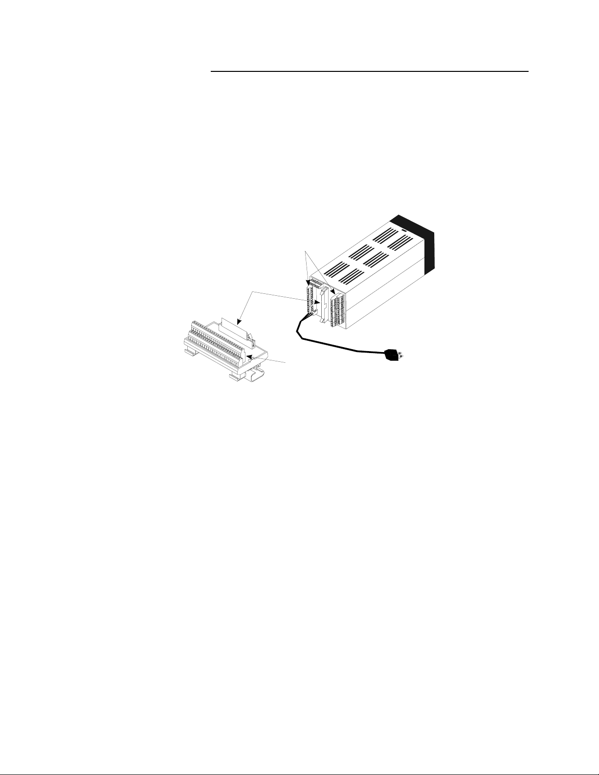
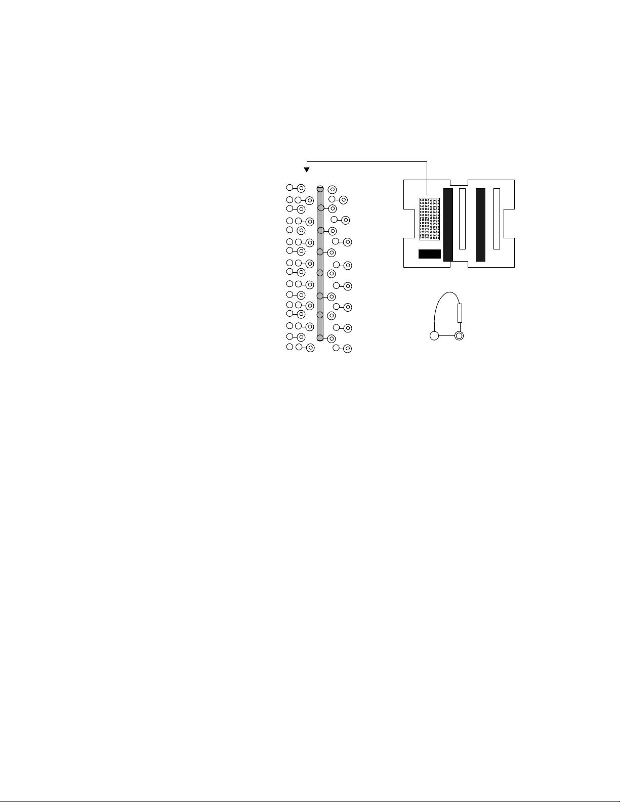
System Diagram
The illustration below shows how the parts of the 8LS are connected.
When unpacking your system, use the diagram and parts list below to
ensure all parts have been shipped. Please don’t hesitate to call Watlow
Anafaze’s Technical Service Department if you have problems with
your shipment, or if the 8LS components are missing or damaged.
Signal Inputs and
Primary Outputs
50-Pin Ribbon Cable
8LS to RTB
8LS
Parts List
50-Pin RTB
Secondary Outputs
and Alarms
•
8LS controller
•
Controller mount kit
•
RTB
•
50 pin flat ribbon cable
•
8LS manual
System Power
2 8LS User’s Guide
Page 11

Safety
Overview
Watlow Anafaze has made efforts to ensure the reliability and safety of
the 8LS
applications. Please note that, in any application, failures can occur.
These failures may result in full control outputs or other outputs which
may cause damage to or unsafe conditions in the equipment or process
connected to the 8LS controller.
Good engineering practices, electrical codes, and insurance regulations
require that you use independent external safety devices to prevent
potentially dangerous or unsafe conditions. Assume that the Watlow
Anafaze 8LS controller can fail with outputs full on, outputs full off, or
that other unexpected conditions can occur.
Install high or low temperature protection in systems where an
overtemperature or undertemperature fault condition could present a fire
hazard or other hazard. Failure to install temperature control protection
where a potential hazard exists could result in damage to equipment and
property, and injury to personnel.
controller and to recommend safe usage practices in systems
The 8LS includes a reset circuit that sets the control outputs off or to the
—
data stored in memory if the microprocessor resets
of a power failure and power return. If a memory-based restart will be
unsafe for your process, program the 8LS controller to restart with
outputs off. For additional safety, program the computer or other host
device to automatically reload the desired operating constants or process
values on return of operating power. However, these safety features do
not eliminate the need for external, independent safety devices in
potentially dangerous or unsafe conditions.
Watlow Anafaze also offers ANASOFT
program for IBM-AT
event of a reset, ANASOFT will reload the 8LS controller with the
current values in computer memory. The user must ensure that this reset
will be safe for the process. Again, use of ANASOFT does not eliminate
the need for appropriate external, independent, safety devices.
Contact Watlow Anafaze immediately if you have any questions about
system safety or system operation.
®
or IBM-PC® compatible computers. In the
®
normally the result
, an optional software
8LS User’s Guide 3
Page 12

Overview
4 8LS User’s Guide
Page 13

Introduction
The 8LS is a powerful 1/4 DIN controller that delivers 8 fully
independent loops of PID control. It can function as a stand alone
controller and as the key element in a computer supervised data
acquisition and control system. An LED front panel display and a touch
keypad are available for local entry of control and other operating
parameters. The 8LS can also be supervised by a computer or
programmable controller through the standard serial interface.
The 8LS features include:
Direct Connection of Mixed Sensors: Versatile analog inputs let you
directly connect most industrial T/C sensors. Thermocouple inputs
feature reference junction compensation, linearization, upscale break
detection, and a choice of
scaling resistors on the 8LS inputs.
Introduction
°
F or °C display. Other analog inputs require
Automatic Scaling: All sensors can be automatically scaled by
entering any two measurement points. For example, to scale a pressure
sensor, enter two points such as 28% is 80 PSI, and 82% is 260 PSI. All
subsequent values will be in PSI.
Selectable Control Outputs: Each PID primary control output can be
selected as digital for on/off, time proportioning, or as analog for
proportional 0-5vdc /4-20madc. The PID secondary output can be
selected as digital for on/off, time proportioning, or distributed zero
crossing. Each loop can be independently set for on/off, P, PI, or PID
control with reverse acting [heat] or direct acting [cool] output.
Complete Process Monitoring: A unique alarm capability is included.
You can set a deviation band alarm, and high and low process [fixed]
alarms independently for each loop. In addition to global annunciator
digital output, each alarm can include a single or grouped digital output.
For example, the digital output from all the high process alarms can be
directed to a single output for automatic process shutdown.
Front Panel or Computer Operation: You can set up and run the 8LS
from the front panel or from a local or remote computer. We offer
ANASOFT, an IBM PC or compatible menu driven program, to set the
8LS parameters. In addition, ANASOFT features graphic trend plotting,
process overviews, printouts, and data archiving.
Multiple Job Storage: You can store up to 8 jobs in protected memory
and access them by entering a single job number. Each job is a set of
operating conditions, including setpoints and alarms. Thus if a single
oven is producing multiple products, entry of the job number will setup
all the loops.
8LS User’s Guide 5
Page 14

Introduction
Dual Output Standard: The 8LS includes dual control outputs for
each loop with a second set of control constants for heating and cooling
applications.
Optional Ramp and Soak: The 8LS is available with a built in
powerful Ramp and Soak programmer for batch processing.
Optional Extruder or Carbon Potential: The 8LS is available with
built in Extruder or Carbon Potential parameters for controlling these
processes.
6 8LS User’s Guide
Page 15

Specifications
Analog Inputs
Analog inputs 8, solid state, differential
Optical isolation 120 Vac between inputs; 175 Vac from input to ground
A/D converter Integrating voltage to frequency
DC voltage range -10 to 60 mV. You can change it with scaling resistors to
Resolution 0.02%, greater than 12 bits
Calibration Automatic zero and full scale
Temperature coefficient Less than 50 ppm/C, 0.005%/°C
Normal mode rejection 60 db at 60 Hz, full scale range maximum
Loop update time 2 times per second, every input
T/C burnout Full upscale reading of input standard
DC milliamp inputs 4-20 mA, 10-50 mA, 0-50 mA, etc., with scaling resistors
Input Range 0-1V, 0-5V, 0-10V, 0-12V, up to 0-25 Vdc, with scaling
Infrared inputs Power supply included, with scaling resistors
Source impedance Measurements are within specification with up to 500
Introduction
any range from 0 to 25V
Accuracy 0.05% at 25°C
resistors
ohms source resistance
Thermocouple Ranges
J -350 to 1400°F -212 to 760°C
K -450 to 2500°F -268 to 1371°C
T -450 to 750°F -268 to 399°C
B 150 to 3200°F 66 to 1760°C
S 0 to 3200°F -18 to 1760°C
R 0 to 3210°F -18 to 1766°C
N -450 to 2370°F -268 to 1299°C
RTD Ranges
RTD1 -148.0 to +572.0°F -100 to 300°C0.1°
RTD2 -184.0 to +1544.0°F -120 to 840°C0.2°
8LS User’s Guide 7
Page 16

Introduction
Control Capability
Number of loops 8, dual output
Control outputs Cycle Time Proportioning, Distributed Zero Crossing, On/Off or Ana-
Digital PID outputs Nominal 5 Vdc at 20 mA to drive optically-isolated solid-state relays
Analog PID outputs Selectable 0 to 5 Vdc at 20 mA maximum or 4 to 20 mAdc 500 ohm
Output resolution 12 bits
Digital Outputs
log; all independently selectable for each loop
Control action Reverse [heat] or Direct [cool], independently selectable for each
loop
Cycle time Programmable for each loop, 1-255 seconds
maximum load
Number 31
Configuration 1 Global Alarm (terminals)
30 for alarms or events (1-4 terminals, 5-30 RTB connector)
Digital Inputs
Pulse Counting Input
Serial Interface
Type RS-232 or RS-485 4 wire, jumper select
Isolation RS-232: optical
Baud Rate 2400 or 9600, menu selectable
Protocol Form of ANSI X3.28-1976, compatible with Allen Bradley
Error check BCC or CRC, menu selectable
No. of controllers Each communications line: 32 with RS-485, 1 with RS-232
Number 12
Configuration 12 for Ramp/Soak triggers
(1-8 RTB connector, 9-12 terminals)
Number Selectable 1 per unit
Type Open collector, 5 Vdc max.
Frequency 1 to 20 Khz
RS-485: To RS-485 Specification
PLC, full Duplex
Power Supply
8 8LS User’s Guide
Power input 85 to 132 Vac, .1A typical, 47 to 440 Hz
Page 17

Installation
Installation
This section explains how to install the 8LS. The instructions are written
for nontechnical users. If you are technically proficient and they seem
simple, at least skim all of the instructions, so you don’t miss anything
vital.
These symbols are used throughout this manual:
DANGER
This symbol warns you of a hazard to human life.
WARNING
This symbol warns you of possible damage to
property or equipment.
NOTE
This symbol denotes information you must know
in order to proceed.
8LS User’s Guide 9
Page 18
Installation
Read This Before Installation
DANGER
Shut off power to your process before you install
the 8LS. High voltage may be present even when
power is turned off! Reduce the danger of electric
shock after installation--mount the 8LS in an
enclosure that prevents personal contact with electrical components.
The 8LS measures input signals that are not normally referenced to ground, so the 8LS inputs and
other signal lines can have high voltage present
even when power is turned off. For example, if you
inadvertently short a thermocouple to the AC
power line.
WARNING
During installation and wiring, place temporary
covers over the housing slots and the rear of the
8LS so dirt and pieces of wire don't fall through
the slots. When you are finished with installation,
remove the covers.
Install the 8LS so the airflow to the slots in the
housing is not restricted after installation. Make
sure that other equipment does not block airflow
to the housing slots.
Use #20 or #22 AWG wires and trim wire insulation to 1/4" (5 mm). Wire should fit inside the
terminal with no bare wire exposed, to prevent
contact between wires and the grounded case. Tin
any stranded wire.
Support power, input and output cables to reduce
strain on the terminals and to prevent wire
removal.
NOTE
Choose a panel location that leaves enough clearance to install and remove the 8LS and its
components.
10 8LS User’s Guide
Page 19
Mounting The 8LS
Installation
The 8LS consists of a 1/4 DIN housing with a front plug in electronics
module. The 8LS-OF (Open Frame) is suitable for sub-plate mounting
inside an enclosure without a front panel. An 8LS-DK will supply the
front panel keyboard with a 10-foot plug- in cable.
For optimum performance when directly connecting thermocouple
inputs, the unit should be protected from thermal shocks whenever
possible. This will minimize any temperature gradients across the
terminal strips and ensure the highest accuracy.
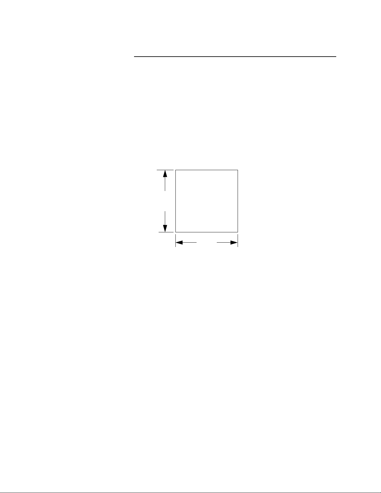
1. Use the dimensions below to cut a hole in the panel.
92 mm
3.6’’
92 mm
3.6 ’’
Cut the hole carefully; the 1/4 DIN specification only allows a front
panel of 96mm x 96mm [3.78in x 3.78in], so there’s not a lot of room
for error.
2. After the hole is cut, insert the 8LS through the front of the panel and
screw the top and bottom clamps into place. If excessive vibration is
anticipated a rear support may be required both for the 8LS and the
interconnecting cables.
8LS User’s Guide 11
Page 20
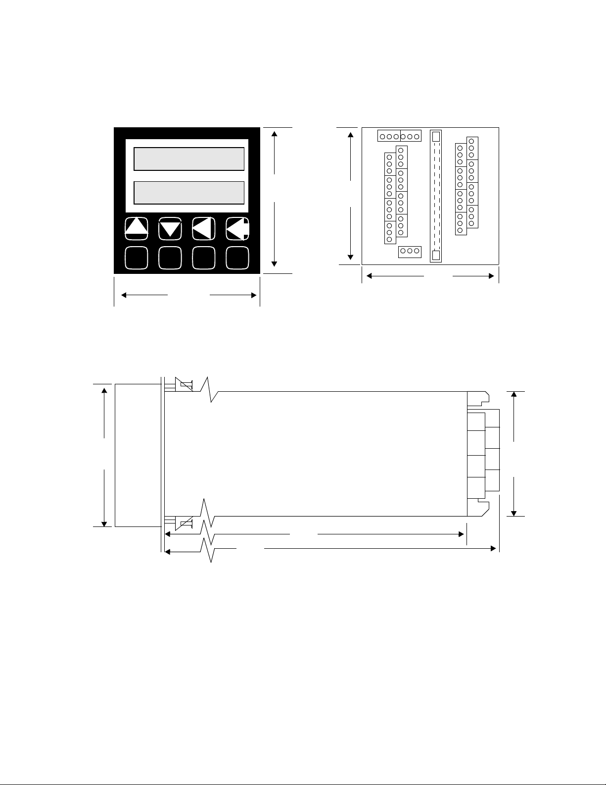
Installation
.
Front
LOOP PROCESS UNITS
1234 56 7 8
ALARM SETPOINT STATUS OUTPUT%
YES
ALARM
ACK
NO
CHNG
SP
3.78’’
96 mm
BACK
MAN
AUTO
ENTER
RAMP
SOAK
3.78’’
96 mm
3.58 ’
90.9 mm
Side
Rear
PIO
TB4
’
TB3
TB1
90.9 mm
TB2
3.58 ’’
3.78’’
96 mm
10.5’’
266.7mm
9.4’’
238.7mm
3.58’’
90.9
mm
12 8LS User’s Guide
Page 21
3.78’’
g
g
(
Installation
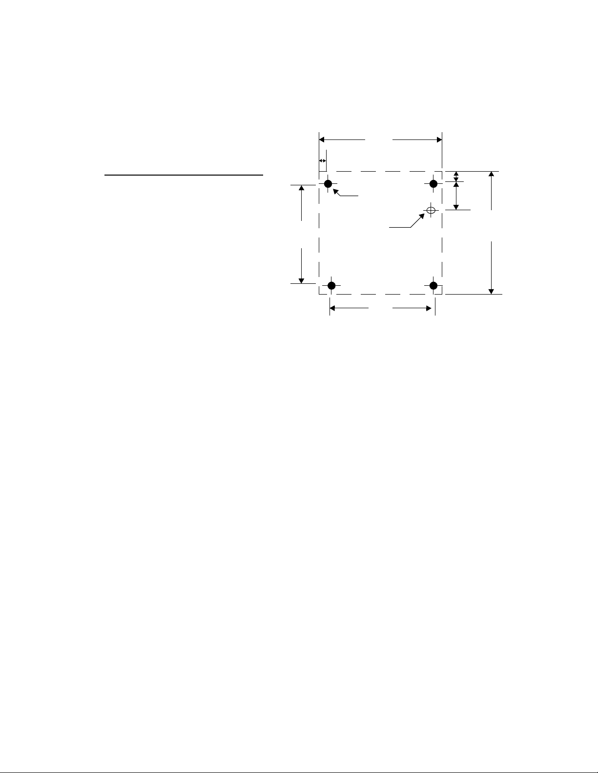
Remote Panel Mounting Dimensions
Notes:
1. Dashed line indicates panel outline.
2. Drill holes as indicated.
3. Install
rommet and feed wire
through grommet.
4. Attach panel usin
from behind).
4 #4 screws
External Wiring
During wiring, it is recommended that the 8LS electronics be removed
or that temporary covers be put over the housing slots to ensure pieces
of wire do not enter the housing and lodge in the electronics. Always
ensure that the housing is clean when the electronics is plugged in.
A successful installation of an 8LS control system depends on selecting
the proper equipment and using correct installation techniques with
appropriate material. One area of concern is the wiring type and
placement of the wiring.
0.29’’
3.20’’
To p
125 dia
4 places
7/16 dia
Insert grommet
3.20’’
0.29’’0.91’’
3.78’’
The wiring is selected according to the function of the wire, the
installation requirements, and the possible mechanical electrical
problems that may occur.
The function of the wire is divided into two basic categories:
Outputs
. The process control requirements will dictate the
Inputs
type
and
of
inputs and the outputs along with the mechanical electrical requirements
of the individual installation.
The term AC power is applied to the 120 VAC control supply. High
power is applied to 240 VAC or higher, primarily used for control loads.
General Wiring Requirements
1. Use stranded wire. Solid wire is recommended for fixed service
and tends to make intermittent connections when moving the field
wiring around for maintenance.
8LS User’s Guide 13
Page 22

Installation
2. Use 20 or 22 AWG size wire. The use of 16,18,20,22, or 24 AWG is
permissible also. The power requirement is not a factor in the wire
size. Only the mechanical strength and the ohmage of the wire may
be factors to consider. Smaller or larger sizes are not easily
installed, may be easily broken and/or cause intermittent connections.
3. Use shielded wire. The electrical shield is used primarily to protect
from unwanted electrical noise.
Normal use of the input wiring shield is to connect one end only to
the 120 VAC panel ground at the 8LS panel location. Another method
is to connect it at the sensor site ground and to the Analog Ground
terminal of the 8LS.
Normal use of the output wiring shield would be to connect one end
only to the 120 VAC panel ground in the panel that the 8LS is
mounted in. Actual use of the shields will be determined by the
installation requirement.
For additional noise suppression measures see NOISE SUPPRESSION FOR Digital Outputs.
4. Use Thermocouple Extension Wire for all thermocouple (T/C)
inputs. Most T/C Ext. Wire is solid wire unshielded. When using
such, the shield function cannot be utilized and only 16, 18, or 20
AWG should be used. Install all T/C wiring in its own conduit away
from AC Power and High Power wiring. Depending on type and wire
size up to 400-500 feet in length may be used to be within stated
accuracy and source impedance.
5. Use multiconductor stranded shielded cable for analog inputs. Most
inputs will use a shielded twisted pair, but some may require a 3 wire
input. Run all analog input wiring in its own conduit away from AC
Power and High Power wiring. Wire sizes of 20, 22, or 24 AWG may
be used.
6. Use multiconductor stranded shielded cable for analog outputs and
PID digital outputs connected to panel mount SSR's. The analog
output will normally use a twisted pair while the digital outputs will
be up to 9 or 20 conductors depending on wiring techniques. All
cables will be shielded. The wiring size will normally be 24 AWG.
The maximum length for the digital outputs should not exceed 25
feet. The maximum length for the analog outputs should not exceed
400 feet. All wiring must be in a separate conduit away from AC
Power and High Power wiring.
When using the 50 conductor flat ribbon cable for the I/O, use of
the 50-pin connector is recommended for both ends of the cable.
The wire is too small to withstand much flexing when connected to
a screw terminal. The cable length should not exceed 15 feet.
7. When installing communications wiring, by pulling in an extra pair, a
sound power phone system could be used for communications
between the 8LS and the computer. This could be used for maintenance, checking calibration and many other functions. A David Clark
#H5030 sound powered system has been used successfully in systems requiring this function.
8. When installing any I/O wiring to the 8LS inside a panel, it should
never be run in the same bundle as AC power wiring.
14 8LS User’s Guide
Page 23

Cable Recommendations
Installation
Wiring bundles of low power Watlow Anafaze circuits next to bundles of high power AC wiring should never be done. The physical
separation of the high power circuits from the controllers should be
of prime importance. In fact, most AC voltage high power circuits are
installed in a separate panel.
Use these cables or their equivalent.
Function MFR P/N
Analog Inputs Belden #9154
Belden #8451
RTD Inputs Belden #8772
Belden #9770
T/C Inputs T/C Ext. Wire 2
Carbon Probe Input Belden #88760 2 18
Digital PID Outputs and Digital
I/O
Analog Outputs Belden #9154
Computer Communication:
RS232, RS422, RS485, or 20
mA
Belden #9539
Belden #9542
Ribbon Cable
Belden #8451
Belden #9729
Belden #9730
Belden #9842
Belden #9843
# of
Wires
2
2
3
3
9
20
50
2
2
4
6
4
6
AWG
20
22
20
22
24
24
20
22
24
24
24
24
8LS User’s Guide 15
Page 24

Installation
Noise Suppression
When using the digital outputs from Watlow Anafaze multiloop
controllers to energize dry contact electrical-mechanical relays with
inductive loads, generation of RFI may become a problem.
This may cause the 8LS display to blank out and then re-energize as if
power had been momentarily turned off. It may also cause the CPU in
the equipment to reset, losing the PID output levels. It may also damage
the digital output IC circuit, thus not being able to energize the digital
outputs. If the IC circuit is damaged, factory repair will be required.
The type of loads that may cause a problem are motor starters, alarm
horns, etc. The RFI is generated upon opening of the metallic relay
contacts.
To correct the problem of RFI noise problems:
1. Use Solid State Relays (SSR) wherever possible in place of electricalmechanical relays (E-M relays).
2. When using E-M relays, if possible do not mount them in the same
panel as the Watlow Anafaze equipment.
3. Separate the 120 vac power leads from the low level input and outputs leads from the Watlow Anafaze. Do not run the digital outputs or
PID control outputs leads in the same wire bundle as any 120 vac
wires. Inputs leads should never be run in the same bundle with any
high power leads.
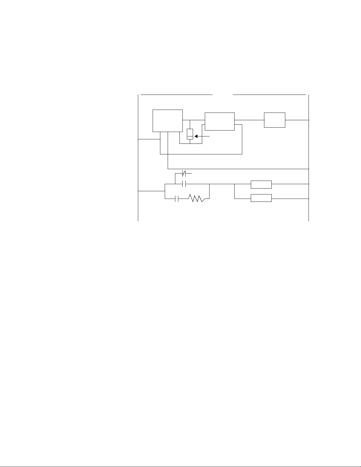
4. If E-M relays are required and must be in the same panel as the Watlow Anafaze equipment, use a .01 uF at 1000 vdc or higher vdc disk
capacitor in series with a 47 ohm 1/2 W resistor across the NO contacts of the relay load contacts. This is the most important step in suppressing RFI from relay contacts. This network is known as arc
suppressor or snubber networks.
5. Use of other voltage suppressing devices may also be used, but are
not normally required. A device known as a MOV rated at 130 vac
for 120 vac control circuits may be placed across the load. This will
limit the peak ac voltage to about 180 vac. A device known as a transorb (back to back zeners) may be used across the digital output. The
rating of 5 vdc should be used. This will limit the dc voltage to 5 vdc
on the digital output loop.
See diagrams for proper placement of the above devices. The parts for
RFI suppression are available from Watlow Anafaze.
16 8LS User’s Guide
Page 25
Installation
g
The above steps should eliminate any noise problems that might be
present with using E-M relays. If, problems persists and/or any
questions about the above steps arises, please call Watlow Anafaze
Technical Service Department at (408) 724 3800.
L 1
8LS
-
+
.01uf
1000 VDC
or higher
K1
NO
NC
47 ohm
1/2 W
120 VAC
-
SSR
+
5 V Transorb
L 2
K1
HORN
MOV
130 VAC ratin
8LS User’s Guide 17
Page 26
Installation
Terminal Block And Connector Layout
The 8LS terminal blocks and connectors are assigned according to the
following two pages. Subsequent sections provide detailed connection
descriptions.
Communications Terminal Block 4
Jumper*
Analog
Ana In 1-
Ana In 2-
Ana In 3-
Ana In 4-
Ana in 5-
Ana in 6-
Ana In 7-
Ana in 8-
Analog
Dig In 10
Logic
COM
COM
COM
Chas Gnd
Term inal
Block 1
2
4
6
8
10
12
14
16
18
20
22
24
1
3
5
7
9
11
13
15
17
19
21
23
Rx- Rx+ Tx- Tx+
6
5
COM
Rx
Analog
COM
Ana In 1+
Ana In 2+
Ana In 3+
Ana In 4+
Ana In 5+
Ana In 6+
Ana In 7+
Ana In 8+
Analog
COM
Dig In 9
Dig In 11
COM
50 Pin
Conn
RS-485 Connections
1234
SHLD
Tx
RS-232 Connections
Termina l
Block 2
10
12
14
16
18
20
22
24
1
2
3
4
5
6
7
8
9
11
13
15
17
19
21
23
PID 1 Out +
4950
R
PID 3 Out +
PID 4 Out +
PID 6 Out +
I
PID 7 Out +
B
B
O
N
Pulse In +
Dig In 12
Dig Out 1
Dig Out 2
Dig Out 3
Dig Out 4
12
Global
COM
Logic
+ PID 2 Out
COM
Logic
+ PID 5 Out
COM
Logic
+ PID 8 Out
COM
Logic
COM
Logic
COM
Logic
+5 Vdc
+5 Vdc
Alarm Out
* It is suggested with noisy electrical environments, a heavy gauge jumper wire be connected between the chassis ground and shield terminals on the rear terminal block as
shown.
18 8LS User’s Guide
Terminal block 3
1
Chas
Gnd
23
AC AC
Neutral
HOT
(green) (white) (black)
Red marker on flat ribbon cable
Page 27

RTB Connections
Installation
The RTB provides the control outputs and additional digital inputs and
outputs as follows:
Terminal Function Terminal Function
1 +5 Vdc 2 +5 Vdc
3 Logic COM 4 Logic COM
5 Spare 6 Spare
7 Spare 8 Spare
9 PID 1 Out 10 Dig 30 Out
11 PID 2 Out 12 Dig 29 Out
13 PID 3 Out 14 Dig 28 Out
15 PID 4 Out 16 Dig 27 Out
17 PID 5 Out 18 Dig 26 Out
19 PID 6 Out 20 Dig 25 Out
21 PID 7 Out 22 Dig 24 Out
23 PID 8 Out 24 Dig 23 Out
25 Dig 5 Out 26 Dig 22 Out
27 Dig 6 Out 28 Dig 21 Out
29 Dig 7 Out 30 Dig 20 Out
31 Dig 8 Out 32 Dig 19 Out
33 Dig 9 Out 34 Dig 18 Out
35 Dig 10 Out 36 Dig 17 Out
37 Dig 11 Out 38 Dig 16 Out
39 Dig 12 Out 40 Dig 15 Out
41 Dig 13 Out 42 Dig 14 Out
43 Dig 1 In 44 Dig 2 In
45 Dig 3 In 46 Dig 4 In
47 Dig 5 In 48 Dig 6 In
49 Dig 7 In 50 Dig 8 In
All digital outputs and the PID outputs on this ribbon connection are
Sink Outputs. They are in reference to the 5Vdc supply. The outputs will
be low when they are on.
All digital inputs are TTL level inputs and may be selected from
software if they will be high/false or low/true inputs.
8LS User’s Guide 19
Page 28

Installation
Analog Inputs
NOTE
When using the RTB, proper polarity of the flat
ribbon cable is necessary for correct pin terminations. Install the red marker indicating pin #1 to
the left when terminal #1 of the RTB is to the left.
The flat ribbon cable should have the red marker
down when installing it on the back of the 8LS. To
confirm proper polarity, check that pin #1 is +5vdc
with respect to pin #3.
Connecting analog signals to the 8LS is normally straightforward. Most
thermocouples can be directly connected and mixed in any order. Other
types of analog signals such as RTD's or mAdc or Vdc require scaling
resistors installed on the 8LS inputs. Some problems may occur that
could reduce accuracy and possibly damage the unit. Below are some of
the potential areas for concern.
Common Mode Voltage
Common mode voltage is the voltage between the ground at the sensor
and the ground at the 8LS. It can be an AC or DC voltage and appears
equally at the high and low input terminals. Frequently it is caused by
large currents flowing in the ground path between the 8LS and the
sensors. Use isolated sensors or ungrounded thermocouples and locate
the 8LS as close as possible to the sensors in order to minimize the
effects. Do not exceed the maximum common mode voltage of 175 Vac.
Normal Mode Voltage
Normal mode voltage appears across the terminals of the input and is
the signal from the sensor plus any undesirable noise. The major cause
of this noise is AC power line pick-up. The effects are reduced by the
8LS capacity to integrate the signal over a multiple of the power line
frequency. Further reduction can be achieved by locating the 8LS near
the sensors and by using twisted and shielded sensor wires.
To ensure accurate readings, the maximum of normal mode plus signal
should not exceed -10mv to +60mv.
Grounding
For best accuracy, observe the grounding recommendations for
connecting each input and output signal. The analog signal grounds
should be connected to the analog ground terminals. The
communication and control outputs should be connected to their
respective grounds. Do not mix the grounds or connect them together. If
possible, route the analog signal cables separately from the
communication, control and power cables.
20 8LS User’s Guide
Page 29
Input Scaling
g
Installation
Source Impedance
Each sensor has a certain output impedance which is effectively
connected across the 8LS input amplifier when a measurement is made.
To reach the rated accuracy, the maximum source impedance should not
exceed 500 ohms. Consult Watlow Anafaze for operation with higher
source impedance.
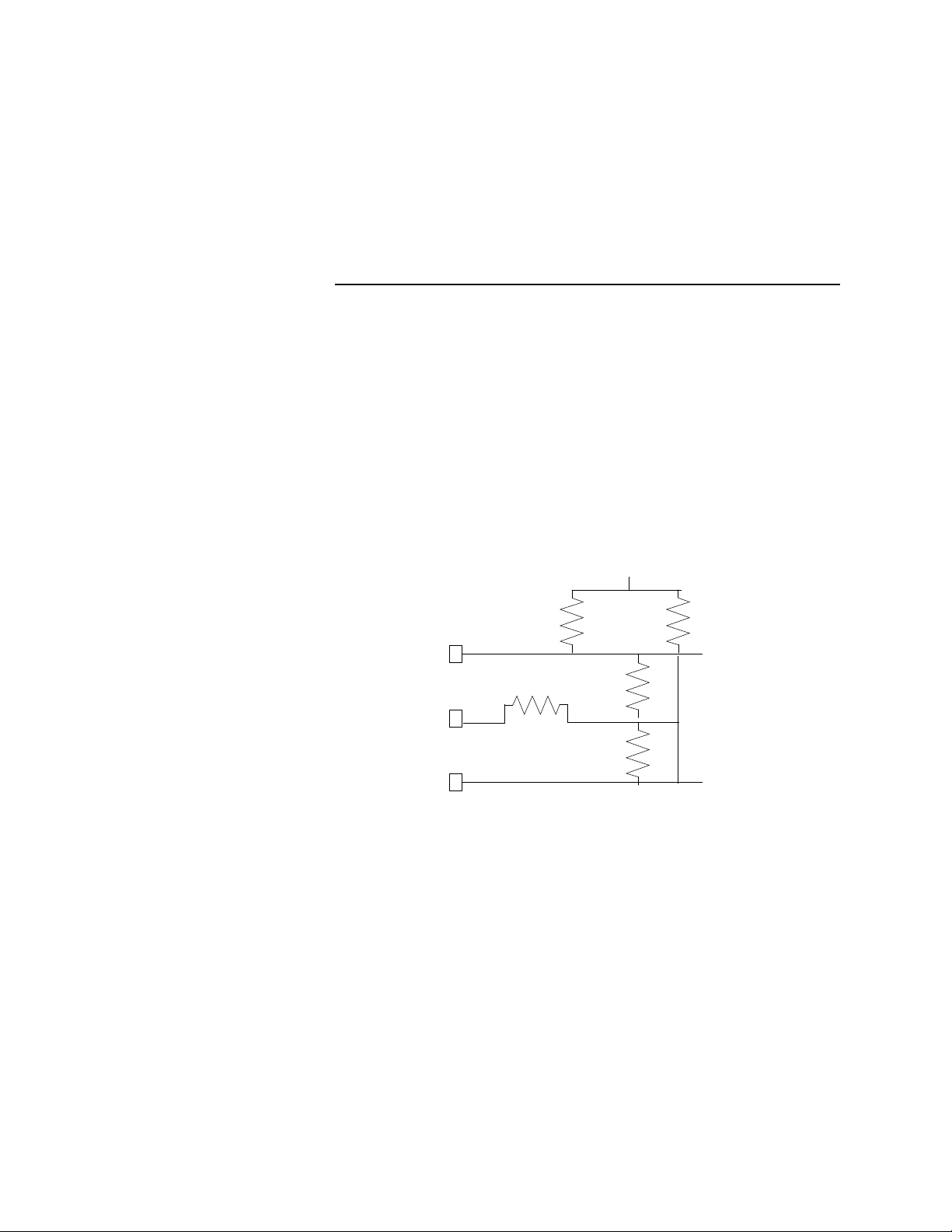
The 8LS contains an area that can be used to install resistors to scale
input voltages and convert milliamp inputs to match the -10 to 60mv (-
16.7% to 100%) input range. The input circuit is designed to enable
connection of current inputs (such as 4 to 20ma), voltage inputs, and 3Wire RTD. Watlow Anafaze will supply input scaling as needed -- order
option 8LS-SI-XX. The input circuit is shown below:
Ana In + = Analog signal + input
Ana In - = Analog signal - input
Ana Gnd = Analog signal ground
Terminal
Block
Ana In
Ana In
Ana Gnd
+
-
RA
+10 Vdc Reference
RC
RB
RD
RB Alternate
+
IN
Measurement
Input
-
IN
Ground
Analo
RA is shorted by a jumper on the PC board, REMOVE THIS JUMPER
TO INSTALL RA.
Resistors should be 0.1% metal film, 1/4 watt. Note that the resistors
must be stood on end due to the compact size of the unit. Other
components such as capacitors can be installed for signal conditioning.
Please consult Watlow Anafaze. The PC board silk screen shows the
resistor locations.
8LS User’s Guide 21
Page 30
Installation
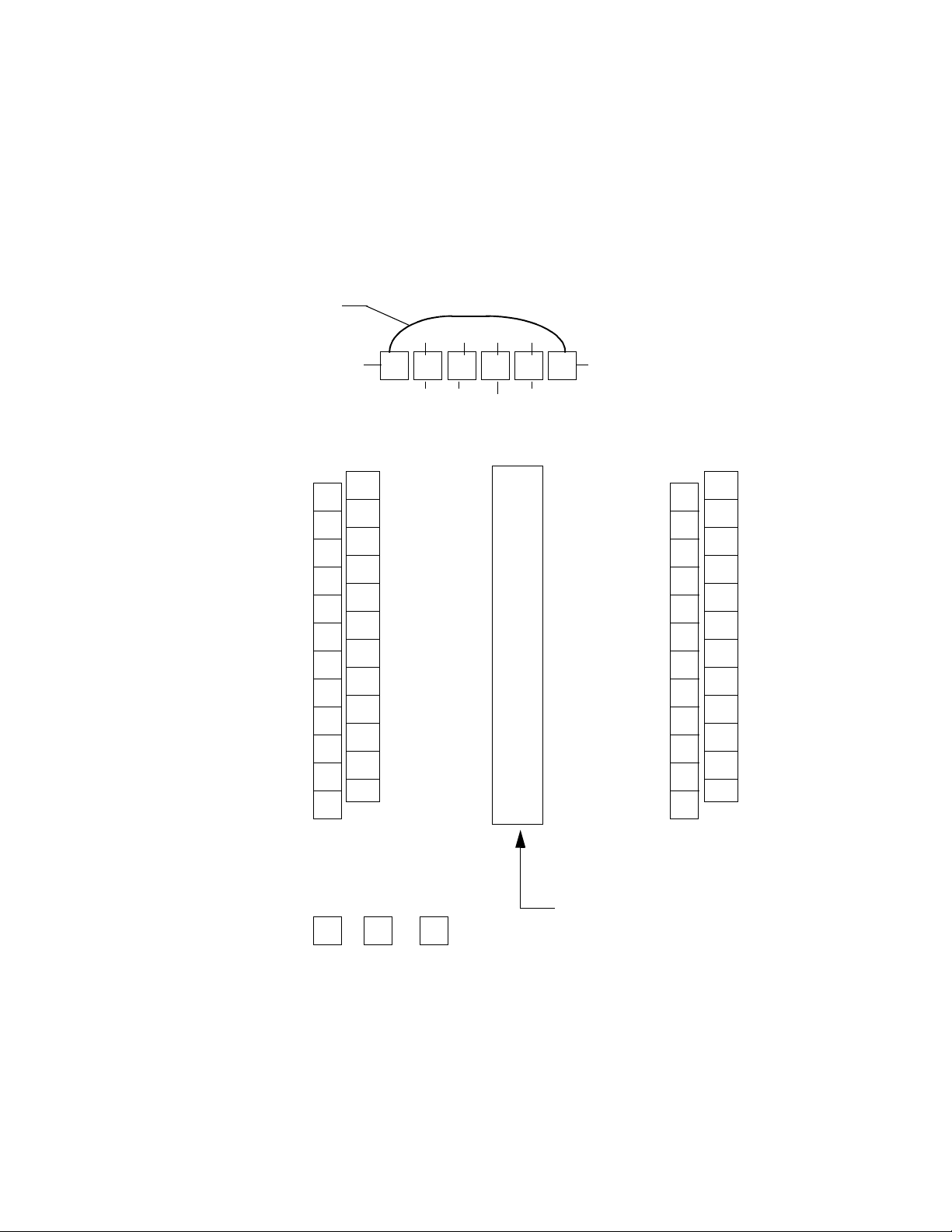
Resistor Installation
For scaling resistors the body of the resistor goes vertically into the hole
with the white silk screen. The lead on the top then goes into the
adjacent indicated hole. The resistor positions are highlighted.
RC1
RB1
RC2
RB2
RC3
RB3
RC4
RB4
RC5
RB5
RC6
RB6
RC7
RB7
RC8
RB8
RD1
RA1
RD2
RA2
RD3
RA3
RD4
RA4
RD5
RA5
RD6
RA6
RD7
RA7
RD8
RA8
22 8LS User’s Guide
Page 31

Voltage Inputs
Installation
DC Voltage inputs should be connected with the positive side to the
High
terminal and the negative side to the
range is -10 to +60 mV. Signals greater than 60 mv must be scaled with
resistors to match the input full scale to 60 mv. The scaling resistor RA
is selected as the voltage dropping and/or current limiting resistor. RB is
selected for the 60 mv full scale dropping resistor. It should normally be
less then 300Ω and no greater then 1000Ω. Any value above 1000Ω for
RB will cause error due to the upscale burnout circuit.
This table shows scaling resistors values.
Low
terminal. The input
Milliamp Inputs
Output
Voltage Range
0-100 mV 499
0-500 mV 5.49 K
0-1 V 6.91 K
0-5 V 39.2 K
0-10 V 49.9 K
The above values are .1% standard metal film resistor values and will
give an accuracy of +
stock. Any possible error due to resistor tolerance error may be
corrected by using the built in linear scaling. Remove the jumper in the
RA location to install RA.
Current inputs from transmitters are accommodated by placing resistors
in the input section to convert the current input into a voltage. Different
current input ranges are accommodated by selecting the proper resistor
values.
A single 0.1% resistor is used as follows:
0.25%. The above values at .1% are our factory
RA RB Accuracy
Ω
Ω
Ω
Ω
Ω
750
750
442
475
301
Ω
Ω
Ω
Ω
Ω
+ .1 %
+ .1 %
+ .2 %
- .2 %
- .1 %
Thermocouple Inputs
4 to 20 ma 0 to 10 ma
RB = 3.000 Ω RB = 6.000 Ω
All thermocouple types may be directly connected to the Watlow
Anafaze 8LS. Types J, K, T, R, S, B, and N linearization and cold
junction compensation are provided standard in the Watlow Anafaze
8LS. For other thermocouple types, optional input ranges are required.
Thermocouples should be connected with the positive lead to
terminal and the negative lead to
only resistor used for T/C inputs and it is a jumper.
Ana In-
terminal of TB1. RA is the
8LS User’s Guide 23
Ana In +
Page 32

Installation
RTD Inputs
The standard industrial RTD is a 100 ohm Platinum three wire
assembly. We highly recommend using the 3-wire RTD. The 8LS will
be configured for the standard three wire RTD input.
Watlow Anafaze offers two standard DIN 385 Curve RTD input ranges,
as shown in the table below:
RTD
Type
RTD1
RTD2
RTD Range resistors are Watlow Anafaze factory stock in .05%
tolerance.
Range RA RB Alternate RC
RTD1 80
RTD2 100
Infrared Non-contact Temp. Sensors
The IRSM (infrared sensing module) is ideally suited for many infrared
non-contact temperature applications. It can be supplied by Watlow
Anafaze as a fully integrated system with the 8LS configured to provide
power for up to four IRSM modules and for direct connection of the
IRSM output. The following connections are required if the IRSM
internal ambient sensor is not used:
Input
Range
-100.0 to +300.0
-148.0 to +572.0
-120.0 to 840.0
-184.0 to +1544.0
Ω
Ω
°
C
°
F
°
C
°
F
22 K
48 K
Display
Resolution
°
0.1
°
0.2
Ω
Ω
22 K
48 K
Ω
Ω
24 8LS User’s Guide
8LS
Signal
Analog In + A Orange Signal Out (0-10 mAdc)
Analog In - B White Signal Ground
Analog Gnd K Shield
+5 Vdc E Red +5 Vdc supply
Logic Gnd C Black Power Ground
Logic Gnd J Brown No Peak Hold
No Connection D Green +15 Vdc supply
No Connection F Blue Ambient Sensor
No Connection H Yellow Track and Hold
Pin Color Function
IRSM Wires
Page 33

Pulse Input
g
Installation
The range of the standard IRSM is 0-1000 degrees F with an output of
0-10ma dc. The input of the Watlow Anafaze 8LS is configured for a 010madc input.
To use more than four IRSM's with the 8LS, use an external power
supply of 8-15vdc.
If desired, a second input may be used to monitor the internal IRSM
ambient temperature. Consult Watlow Anafaze for more information.
The single pulse input is used when a speed or flow input is available as
a Open Collector signal of 5Vdc maximum from the transducer. The
frequency range of the input is from 1Hz to 20KHz. The sample time
period is adjustable from 1 to 20 seconds. To enable the pulse input,
select PLS for the input type of the loop that is to be used for the pulse
input. Do not use the analog input terminals. Connect the transducers
output using shielded wiring to the pulse input pin 12 of TB2 as shown:
Transducer
+
5 Vdc Maximum
-
8LS TB2
12
13
Pulse
Input
ic
Lo
Ground
Carbon Probe Input
The standard zirconia carbon probe as used by the metal treating
industry will have two outputs.
One is the T/C output. A type K, N, R, or S is used. This output will use
standard T/C Extension Wire connecting it to the 8LS.
The second output is the carbon probe output. This output requires using
a special cable due to the electrical and temperature requirements of the
probe and its environment. The cable requirements are two wire with
o
shield with a high ambient temperature rating of at least 150
C.
8LS User’s Guide 25
Page 34

Installation
The Belden cable part number 88760 is highly recommended for the
connection of the carbon probe to the 8LS. An equivalent cable may be
used.
Chas
Gnd
TB4
T/C
Probe
56
1
2
+
-
+
_
Shield
Probe Cable Belden #88760.
Connect Shield to TB4-6 Chassis Ground.
No. of CP
Loops
CP-1 1 2
CP-2 3 4
CP-3 5 6
CP-4 7 8
4
6
Loop Number
3
5
T/C input
1234
Carbon Probe Input
Loop No.
26 8LS User’s Guide
Page 35

Control Outputs
WARNING
Control outputs are connected to the 8LS logic
ground. Be careful when you connect external
devices that may have a low side at voltage other
than controller ground, since you may create
ground loops.
If you expect grounding problems, use isolated
solid state relays and isolate the control device
inputs.
PID Output Termination TB (Primary) or Flat Ribbon (Secondary)
Installation
The 8LS PID control outputs are Dual Outputs for each loop. For
identification these are called primary and secondary control outputs.
Therefore, each loop has control of two outputs, a primary and a
secondary. These are set by factory default to be for Heat/Cool
applications whether or not they will be used for heat/cool operation.
Primary simply means that it is physically implemented on the terminal
block instead of the 50 pin ribbon cable. This is because many
applications use only one output, and a user will not have to buy a
remote terminal block to use the primary output. Also, the primary
outputs are the only ones which can be programmed to analog. Primary
outputs cannot be programmed for DZC outputs.
The default output assignment is for the heat output to be on the primary
terminal outputs and the cool output to be on the secondary 50 pin
ribbon outputs. This can be changed, however, on an individual channel
basis by assigning the heat output to the ribbon cable. The primary and
secondary outputs do not have to be used for heat/cool since:
1. Each output may be individually programmed as a different type:
ON/OFF, TP (both outputs), DZC (secondary only) and ANALOG
(primary only).
2. Each output can be individually programmed to be direct or reverse
acting [both outputs can be the same].
3. There may be a deadband programmed for heat/cool, and in that
deadband both outputs will be off.
8LS User’s Guide 27
Page 36

Installation
g
g
Pid Control Relay Outputs
Primary Screw Terminal Outputs
Typical ON/OFF, TP, DZC control outputs utilize external opticallyisolated solid-state relays. These relays use a 3 to 32vdc input for
control and can be sized to switch up to 100amps at 480vac. For larger
currents these relays can be used to drive contactors.
The primary PID positive output for each loop is located on the screw
terminal blocks and labeled
Ctl Out 1+
through
Ctl Out 8+.
The
negative side of the output is Logic Ground.
NOTE
Primary control outputs are a source supplying
5vdc when the output is On. They should be connected to the positive (+) side of SSRs. Analog
outputs are positive with respect to logic ground.
Connections are made as follows:
Screw Terminal
Block 2
PID Ctl Out 1+
(TP or ON/OFF)
PID Ctl Out 2+
(TP or ON/OFF)
Lo
ic Ground
PID Ctl Out 3+
(Analo
4-20 mAdc)
Pin
#
SSR 1
SSR 2
++--
2
3
1
4
I/P
+-
28 8LS User’s Guide
Page 37

Digital Outputs On The Screw Terminal Blocks
g
g
y
g
NOTE
Alarms and events outputs are sinking +5vdc to
ground when the output is ON. They should be
connected to the minus (-) side of SSRs.
Connections are made as follows:
Installation
Primary Analog Outputs
Event
SSR 2
_
Control
SSR 3
++
__
+
Screw Terminal
Block 2
ital Out 1
Di
(Alarm ON/OFF)
Di
ital Out 2
(Event On/Off)
+5Vdc Suppl
PID Ctl Out 1+
(TP or On/Off)
ic Ground
Lo
Alarm
SSR 1
Pin
#
16
18
21
4
1
See Terminal Block and Connector Layout.
The 8LS provides either 4 to 20mA with 500 ohms maximum load or 05vdc at 5mA maximum. Selection is made on internal dip switches.
The control outputs are shipped as voltage outputs, and can be
converted from voltage to current by changing the dip switch settings on
the control output card. If you are using the output as a digital mode,
such as TPV, you should leave the output in voltage mode. These
switches are accessible from the top of the electronics assembly after it
has been removed from the housing.
There are two dip switch packages on the Output Card, each with 8
switches. Each channel requires two switches. The dip switch package
near the rear panel controls the odd numbered outputs, while the dip
switch package near the front panel controls the the even channels.
When the unit is viewed from the top, with the rear panels to the left, the
channels are in ascending order from left to right [See silk screen on the
printed circuit board].
For each channel, a switch pair will have the switches set in
complementary states. If the first switch of the pair is down and the
second is up, the output is in voltage mode. If the first is up and the
8LS User’s Guide 29
Page 38

Installation
second is down, the output is in current mode. Thus if switch 3 is down
and 4 is up on the dip switch package near the rear panel, then channel 3
is set for voltage.
Rear DIP Switch
F
18
O
o
F
18
Output switches are set to voltage mode; in CPU switch all special
features are set to Off.
Analog Output Dip Switch Setting for 0-5v/4-20mA
Loop Switch Position 0-5 Vdc 4-20 mA
1 Rear 1 O F
1 Rear 2 F O
3 Rear 3 O F
3 Rear 4 F O
5 Rear 5 O F
5 Rear 6 F O
7 Rear 7 O F
7 Rear 8 F O
2Front 1 O F
2Front 2 F O
4Front 3 O F
4Front 4 F O
6Front 5 O F
6Front 6 F O
8Front 7 O F
8Front 8 F O
Odd
CPU DIP Switch
Front DIP Switch
F
18
O
Even
30 8LS User’s Guide
O indicates an On switch, F indicates an Off switch.
Page 39

CPU Dip Switch
Installation
WARNING
Normal mode of operation is for all positions to be
Off. Positions that are On will effect the 8LS normal operation mode.
Position 1 ON--Clears the battery backed RAM and re-initializes the
factory default values into the RAM.
1. Turn off power.
2. Set DIP switch position 1 ON.
3. Turn on power for 10 seconds, and then turn it off.
4. Set DIP switch position 1 OFF.
5. Turn on power.
Positions 2 to 8 are not used for normal 8LS operations. All positions
must be OFF.
NOTE
Turn off the power before you set any DIP switch.
After the new settings, turn on the power to energize the new DIP switch settings.
Secondary Outputs 50 Pin Ribbon Cable
NOTE
Secondary control outputs are sinking +5vdc to
ground when the output is on. Connect them to the
minus (-) side of SSRs.
8LS User’s Guide 31
Page 40

Installation
Connections are made as follows:
Remote Terminal Block
Ribbon Cable Pin
PID Ctl Out 1
PID Ctl Out 2
+5Vdc Supply
Or
9
11
1
SSR 1
+-+-
SSR 2
32 8LS User’s Guide
Page 41

Communications Set-up and Connections
The 8LS offers two types of serial communications: RS- 232 and RS-
485. Up to 32 addresses can be set in the 8LS for one communication
line. RS-232 can not be used for more than 1 controller.
Unless otherwise specified in the purchase order, units are shipped
configured for RS-232. They may be easily modified to RS- 485 by
moving a cable and a jumper plug. These may both be reached from the
bottom of the electronics assembly after it has been removed from the
chassis. The cable has a 4 pin connector which plugs into 4 pins on an 8
pin header on the processor card. RS-232 is on the 4 pins closest to the
front panel, while RS-485 is on the 4 pins nearest to the rear panel. The
connector is always installed with the red lead nearest the front panel.
The jumper plug is located near the cable connector. The position
closest to the rear panel is for RS-232, while the position nearest the
front panel is for RS-485.
Installation
RS-232 Connections
RX Pin 3 RX Pin 2 TX Pin 2 White
TX Pin 2 TX Pin 3 RX Pin 4 Red
GND Pin 7 GND Pin 5 GND Pin 5 Black
The optically-isolated RS-232 interface is connected using the
Communications terminal block 1. See table below for connections.
Computer Connector 8LS Watlow Anafaze
DB 25 DB 9 TB 4 Pin No. Cable
The computer pins are for the normal 25 pin RS-232 connector [DB25]
and the normal 9 pin connector [DB9]. On some computers transmit TX
and receive RX may be reversed. Please check your computer manual
for details.
232
232485
485
8LS User’s Guide 33
Page 42

Installation
RS-485 Description And Connections
The RS-485 is a voltage balanced long distance multi-point
transmission interface. It may use 2 or 4 lines depending on system
requirements. The 8LS uses four lines [two lines can be accommodated
on special order -- contact Watlow Anafaze].
RS-485 Description
The EIA Standard RS-485 specifies only the electrical characteristics of
generators (transmitters) and receivers for use in digital multi-point
systems. The specification of transmission lines, signaling rates,
protocols, etc. is left entirely up to the user. The transmitters and
receivers selected by Watlow Anafaze also meet the requirements of
RS-422.
The following information is intended to make recommendations for the
application of the RS-485 interface to Watlow Anafaze equipment.
The maximum signaling rate used by the Watlow Anafaze 8LS and
associated equipment is 9600 baud. Since this is far below the
maximum signaling rate covered by the specification, satisfactory
performance may be expected without strict adherence to all of the
design rules. Watlow Anafaze has presented conservative
recommendations to insure reliable operation. If deviations are
necessary, please contact Watlow Anafaze.
Cable Recommendations
We recommend twisted shielded pairs for the RS-485 cables. The
transmitters and receivers specified in RS-485 are very tolerant of cable
characteristics, and some leeway is possible unless distances and
signaling rates push the specification limits.
One requirement is very important, as it impacts performance even
down to low frequency operation. The loop resistance of the
transmission line [wire only -- not terminating resistor] must not exceed
Ω
200
for a properly terminated line with a reasonable margin for noise.
Thus the following recommendations for distance and wire gauge
should be observed:
Distance Wire Gauge Recommended Cable
4000 ft. 24 AWG Belden # 9729/9842
6000 ft. 22 AWG Belden # 9184
The use of a shield depends on the noise environment and grounding
considerations. The above cables are shielded.
34 8LS User’s Guide
Page 43

Installation
RS-485 Connections
Connection of Watlow Anafaze controllers to a system computer
requires an interface at the computer to convert RS-232 levels to RS-
485. Watlow Anafaze recommends two options:
•
B&B Electronics 485OIC with 485PS2 or 485OISPR with 485PS.
•
Black Box Model LD485A. The LD485A should be configured for
DCE operation, with the RTS/CTS delay jumper in the "on" position. Watlow Anafaze can supply this converter configured and
checked out with the system on request.
Jumper setup for the B&B Electronics:
1. JP1 Off
2. JP2 Installed
Normal Operation LD485A installation setup:
1. DCE operation (Dip shunt in XW1A socket)
2. Normal operation (Front panel switch out)
3. Full Duplex operation (Jumper W8 on Full)
4. RTS/CTS Delay set to ON (Jumper W9 to ON)
5. Unterminated operation (Switch S2 to Unterm)
6. No jumper at position W7
The RS-485 specification is for "balanced line" operation, and is not
true differential. Thus a common connection is required between all
stations on the communication line. This can be accomplished by either
a 5th wire (which could be shield) or a common ground connection.
The Watlow Anafaze system more conveniently supports the common
ground connection, although 5th wire can be supported if required due
to common mode voltages generated in a given installation. The 3rd
wire connection would be required only if the "common mode" voltage
between stations exceeds the RS-485 specification of 7 volts peak.
To make sure the communication system works, the controller chassis
must be electrically tied to Earth ground, and the host computer
communication must be tied to Earth ground. If the host computer RS-
232 communication is not referenced to Earth ground, install the 100
resistor in W7 as recommended by Black Box.
Ω
The following diagram shows the recommended system hookup. The
transmitter from the host computer connects in parallel to the controller
receivers, and the host computer receiver connects in parallel to the
controller transmitters. A single "daisy chain" is recommended. Octopus
connections or "spurs" are discouraged.
8LS User’s Guide 35
Page 44

Installation
A termination resistor is required at each end of the transmission line.
This is accomplished by applying a 200
Ω
resistor across the line at the
farthest point from the computer transmitter. Check with Watlow
Anafaze for setting the Black Box SW2 to the "term" position to
terminate the computer receive line.
The fifth wire for RS-485 communications is recommended for noisy
environment.
NOTE
Connect the cable shields to equipment ground
only at the 8LS controller sites. Do not connect the
shield at the computer site to Ground. Connect a
200 ohm terminating resistor between RX- and
RX+ at the 8LS.
For multiple units connect the system in parallel as follows:
B&B Electronics
485OIS 485OIC
DB-25 Screws
#2
#14
TDA
TDB
Black Box
LD485A
TXA
TXB
8LS (1
+ # 4
RX
- # 5
RX
)
8LS (n)
RX
RX-
+ # 4
# 5
Or
#5
#17
The "fifth" 12 VDC Com 12 VDC Com Logic COM Logic COM
wire
RDA
RDB
RXA
RXB
TX
TX
+ # 2
- # 3
TX
TX
+ # 2
- # 3
200
36 8LS User’s Guide
Page 45

Using the 8LS
g
g
j
gg
j
g
g
g
g
This Chapter will show you how to use the 8LS from the front panel.
Front Panel
The 8LS front panel provides a convenient interface with the controller
for both viewing the process conditions and operating the controller.
You can program and operate the 8LS with the front panel keys shown
below, or you can use ANASOFT, a program designed specifically for
Watlow Anafaze controllers.
Using the 8LS
Yes
Select a menu
Answer Yes to Yes/No
prompts.
Increase a number or
choice
Alarm Ack
Acknowled
reset
e an alarm,
lobal alarm digital
output
No
Skip a menu
Answer No to Yes/No
prompts.
Decrease a number or
choice
LOOP PROCESS UNITS
1234 56 78
ALARM SETPOINT STATUS OUTPUT%
YES
NO
BACK
ENTER
Enter
Store Data or
choice after
editin
Proceed to the
next menu
ALARM
ACK
CHNG
SP
MAN
AUTO
RAMP
SOAK
Ramp/Soak
Assi
n R/S profile
to a loop
Perform operations
Change Setpoint
Ad
ust the setpoint
Man/Auto
To
le loop status
on existin
Back
Abort editin
Return to previous men
profile
u
between manual and
Auto.
ust output power level
Ad
of loops in Manual mode
8LS User’s Guide 37
Page 46

Using the 8LS
Front Panel Keys
YES
NO
BACK
Yes /U p
Press Yes to
•
Select a menu when prompt is blinking
•
Answer Yes to Yes/No prompts
•
Increase a number or choice you are editing
No/Down
Press No to
•
Skip a menu when prompt is blinking
•
Answer No to Yes/No prompts
•
Decrease a number or choice you are editing
Back
Press Back to
ENTER
ALARM
ACK
•
Abort editing
•
Return to a previous menu
Enter
Press Enter to
•
Store data or menu choice after editing
•
Proceed to the next menu
Alarm Ack
Press Alarm Ack to
•
Acknowledge an alarm condition, reset global alarm digital output
38 8LS User’s Guide
Page 47

CHNG
SP
MAN
AUTO
Chng SP
Press Chng SP to
•
Adjust the setpoint on displayed loop
Man/Auto
Press Man/Auto to
•
Toggle loop status between Manual and Auto
•
Adjust output power level of loops in Manual mode
Using the 8LS
RAMP
SOAK
Ramp/Soak
Press Ramp/Soak to
•
Assign a Ramp/Soak profile to selected loop
•
Perform operations on profile you have assigned
NOTE
If the Ramp/Soak function is not installed, this key
has no function.
8LS User’s Guide 39
Page 48

Using the 8LS
Displays
Bar Graph Display
The next section discusses the 8LS displays:
•
Bar Graph display
•
Single Loop display
•
Scanning display
•
Alarm display
This is the default display on power-up. It provides a system overview
by displaying a deviation bar graph for each loop. Loop status including
acknowledged alarms, manual or auto are also displayed.
LOOP PROCESS UNITS
1234 56 78
AAAAMM
A
M
ALARM SETPOINT STATUS OUTPUT%
The upper display shows the Bar Graph for each loop.
The highest and lowest level of the Bar Graph display are the upper and
lower deviation alarms. If deviation alarms are Off, the display range is
+
5% of setpoint. The intermediate levels are linearly spaced between
the upper and lower limits.
The lower display shows each loop’s status. The table below shows the
loop status symbols.
Loop Status Symbol
Loop
Function
AUTO A Single output loop is in automatic control mode.
HEAT H
COOL C
MANUAL M Loop is in manual control mode. Output power
Loop Display
T
L
The output power percentage displayed is for the
Dual output loop is in automatic control and the
heat output is active. The output power percentage
displayed is for the heat output.
Dual output loop is in automatic control and the
cool output is active. The output power percentage
displayed is for the cool output.
percentage displayed is for the heat output.
Description
heat output.
40 8LS User’s Guide
Page 49

Using the 8LS
The table below shows the status symbols for the Ramp and Soak
option.
Loop Status Symbol
Loop Function Loop Display
START S Ramp/Soak profile loaded, ready to start
RUN R Ramp/Soak profile is running
HOLD H Ramp/Soak profile is in hold
WAIT W Ramp/Soak loop is waiting for a trigger state to be
TOLERANCE
ERROR
Single Loop Display
Description
satisfied
T Ramp/Soak loop is out of tolerance and loop is in
hold
If an acknowledged alarm exists, the Bar Graph is replaced by an alarm
symbol.
Press Back to see the Single Loop display.
This display shows the detailed information for one loop at a time.
Press the Back key to return to the Bar Graph display.
LOOP PROCESS UNITS
8
1234 56 7 8
76 F
°
Scanning Display
Alarm Display
130
ALARM SETPOINT STATUS OUTPUT%
Pressing both Ye s and No arrow keys when you’re in Single Loop
display, activates the Scanning display.
In this mode, the controller will automatically step through the active
channels, showing the Single Loop display for each, for about a second.
Press any arrow key to return to the Single Loop display.
The Alarm display is the same as the Single Loop display except the
alarm status is flashing.
A
100
8LS User’s Guide 41
Page 50

Using the 8LS
The table below shows the alarm symbols.
Alarm Symbol
High process
High deviation
Low deviation
Low process
Tolerance error T
The Alarm display interrupts any system display. If more than one alarm
is present, the first one is shown.
When you press the Alarm Ack key, the flashing stops but the alarm
indicator remains as long as the alarm condition exists.
42 8LS User’s Guide
Page 51

Operator Menus
Changing the Setpoint
Using the 8LS
You can perform these tasks from Single Loop display.
Press CHNG SP from the loop you want to change. This display
appears:
LOOP PROCESS UNITS
5
1234 56 7 8
Selecting Status Mode
SP ? 25
ALARM
SETPOINT
•
•
•
•
•
Ye s
Press
Ye s
Press
Enter
Press
Press No or
new setpoint.
Man/Auto
Press
appears:
LOOP PROCESS UNITS
STATUS
to change the setpoint.
or No to change the setpoint value.
to save your changes and return to Single Loop display.
Back
to return to Single Loop display without saving the
from the loop you want to change. This display
OUTPUT%
6 = AUTO
1234
567
8
SET? TUNE
ALARM
SETPOINT
•
Press No to switch between Auto, Manual, and Tune.
•
•
Ye s
Press
Back
Press
changing the mode.
STATUS
OUTPUT%
and then
if you want to go back to Single Loop display without
Enter
to store your choice.
8LS User’s Guide 43
Page 52

Using the 8LS
Autotune
If you have set the current loop to Manual control, this display appears
after you press Enter:
LOOP PROCESS UNITS
6 SET MAN
1234
OUT
ALARM SETPOINT STATUS OUTPUT%
•
Press Ye s to change the output power.
•
Press Ye s or No to select a new power output level.
•
Press Enter to store your choice and go back to Single Loop display
If you set the current loop control status to Tune and press Enter, the
controller automatically sets the loop to manual control, 100% output.
The autotune function then calculates the appropriate PID constants for
the loop and puts the loop in automatic control with the calculated PID
values.
567
H
? 0
T
8
Ramp/Soak
The Autotune function will abort if:
•
Process variable goes over 75% of the setpoint.
•
PID constants were not calculated after 10 seconds (a failure of some
sort).
Use the Ramp/Soak key only if the optional Ramp/soak package is
included in the controller. Information pertaining to programming and
operation of ramp and soak profiles is included in the Ramp/Soak
section.
44 8LS User’s Guide
Page 53

Setup
How to enter the Setup menus?
Setup
The Setup menus let you change the 8LS detailed configuration
information.
If you have not set up a modular system before, or if you don’t know
what values to enter, please read the next section first, Tuning and
Control, which contains PID tuning constants and useful starting values.
1. In Single Loop display, select the loop you wish to edit.
2. Enter this pass sequence: Enter, Alarm Ack, and Chng SP.
How to edit a menu?
ENTER
3. The first Setup menu appears.
•
Press Ye s to select this menu or No to advance to the next menu.
(When you select a menu, the blinking question mark changes to an
equal sign.)
•
Press Ye s (up) or No (down) to toggle between the options.
•
Press Enter to store the value you have selected, or Back to stop
editing and return to the main menu.
The Setup section contains detailed information about the submenus of
the main menus.
The next page shows a diagram of the six main menus (plus the Ramp/
Soak main menu if the option’s installed) and all their submenus.
ALARM
ACK
CHNG
SP
8LS User’s Guide 45
Page 54

Setup
y
y
y
y
y
y
g
g
g
g
g
g
g
g
g
y
y
g
y
Setup Setup Setup
Globals? control?
Save as
job# ?
Restore
Job# ?
Alarm
?
dela
R/S time
base?
Panel
lock?
Power up
outs?
Contrllr
addr?
Comm err
chk?
Comm
baud?
Input?
Input type?
Input smplt?
(only Pulse)
Input unit?
Hi PV?
(only Linear &
Pulse)
Hi RDG?
(only Linear &
Pulse)
Lo PV?
(only Linear &
Pulse)
Lo RDG?
(only Linear &
Pulse)
Offset?
(T/C & RTDs)
Control
PB
Control
H
TI
T
Control
H
TD
T
Control
H
FIL
?
T
Control
C
PB
?
L
Control
C
TI
L
Control
C
L
TD
Control
C
FIL
L
Control
spr?
H
T
?
?
Comm
ptcl?
Setup
Outputs?
Outputs
?
HTC
p
T
?
L
Outputs
?
CT
HTC
?
L
Setup
Alarms?
Alarms
HP?
Hi pro
outpn?
Setup
R/S Pro?
R/S pro
Prof ?
R/S pro
?
Cop
Test I/O ?
INS =
1 1 1 1 1 1 1 1
1 1 1
Te s t o u t
NR ?
Outtol
Outputs
H
Act
?
TCL
Outputs
HTC
Lim
?
Outputs
H
Ltm
?
TCL
Alarms
Dev?
T ?
Read
Hi dev
L
Outpn?
Lo dev
Outpn?
SP ?
Read
Events ?
out
Di
NR01 ?
Extrst
Outputs
HTC
L
NLO
?
?
Alarms
LP?
In NR ?
Edit
HTC
L
out?
Lo pro
Outpn?
Se
?
Se
T ?
?
Alarms
Dbd?
Se
Alarm
?
Dl
SP ?
Se
Events ?
AC line?
Se
Triggrs ?
PROM
info
The R/S menu appears only if
the Ramp and Soak option
is installed in
not, the Test I/O displa
ri
ht after the Setup Alarms
.
displa
our 8LS. If it ’s
appears
Se
To l ?
Se
Last ?
Edit
Se
?
46 8LS User’s Guide
Page 55

Setup Global Parameters Menu
The Setup global parameters menu looks like this:
LOOP PROCESS UNITS
SETUP
1234 56 7 8
GLOBALS?
ALARM
SETPOINT
Answering Yes to this prompt gets you into the globals submenus.
Below is the setup global parameters menu tree. Notice the default
values inside the boxes.
STATUS
Setup
OUTPUT%
Save as
Job #? 1
Restore
Job # ? 1
Alarm
Delay? 0
R/S Time
Base ? H/M
Panel
Lock? Off
Power Up
Outs? Off
Setup
Globals?
Contrllr
Addr? 1
Comm Err
Chk? BCC
Comm
Baud? 96
Comm
Ptcl? ANA
AC Line?
60 HZ
PROM
Information
8LS User’s Guide 47
Page 56

Setup
Save as Job
Use this menu to save the job information for every loop to one of eight
jobs in the battery-backed memory.
LOOP PROCESS UNITS
SAVE AS
1234 56 7 8
JOB #? 1
ALARM
SETPOINT
STATUS
OUTPUT%
Restore a Job
Set Alarm Delay
Selectable Range:
Use this menu to load a job from the memory .
LOOP PROCESS UNITS
1-8.
RESTORE
1234 56 7 8
JOB # ? 1
ALARM SETPOINT STATUS OUTPUT%
Selectable Range:
Use this menu to set a startup delay for all system alarms. Alarm
checking will be delayed for the number of minutes you enter. This is
used to avoid nuisance alarms when starting up a system.
LOOP PROCESS UNITS
The last job number or job 1.
ALARM
1234 56 7 8
48 8LS User’s Guide
DELAY ? 0
ALARM
SETPOINT
Selectable Range:
STATUS
OUTPUT%
0-60 minutes.
Page 57
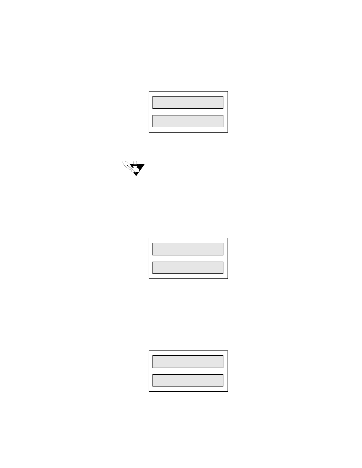
Set R/S Time Base
Setup
Use This menu to set the global ramp and soak time base to units of
hours and minutes or minutes and seconds. All time entries in r/s
profiles will assume the units you set here.
LOOP PROCESS UNITS
R/S TIME
1234 56 7 8
BASE?H/M
ALARM
SETPOINT
STATUS
OUTPUT%
Lock Panel
Power Up Output Status
Selectable values:
Hours and minutes or minutes and seconds.
NOTE
This prompt appears only if your 8LS has the
Ramp and Soak option installed.
Use this menu to disable the front panel keys
Ramp/Soak
LOOP PROCESS UNITS
.
Chng SP, Man/Auto
PANEL
1234 56 7 8
LOCK?OFF
ALARM SETPOINT STATUS OUTPUT%
Selectable values:
On or Off.
, and
Use this menu to configure the initial power-up state of the control
outputs. If you choose Off, all control outputs are initially set to Manual
mode at 0% output level. If you choose Mem, the outputs are restored to
their condition when power was removed.
LOOP PROCESS UNITS
POWER UP
1234 56 7 8
OUTS?OFF
ALARM
SETPOINT
Selectable values:
STATUS
OUTPUT%
Off and Mem.
8LS User’s Guide 49
Page 58

Setup
Controller Address
WARNING
Set safe start up conditions. Do not use memory
startup if there is any chance the process could
start in an unsafe state.
Use this menu to set the 8LS controller address. This address is used for
communications and each 8LS in a system must have a different
address. Begin with address 1 for the first controller and assign each
subsequent controller the next higher address.
LOOP PROCESS UNITS
CONTRLLR
1234 56 7 8
ADDR? 1
ALARM SETPOINT STATUS OUTPUT%
Selectable range:
Communication Error Checking
Use this menu to set the data check algorithm used in the WatlowAnafaze communications protocol.
LOOP PROCESS UNITS
COMM ERR
1234 56 7 8
CHK? BCC
ALARM SETPOINT STATUS OUTPUT%
Selectable values:
Redundancy Check).
NOTE
If you are using ANASOFT, be sure to set ANAINSTL to the same error checking method you set in
this menu.
1 to 32.
BCC (Block Check Character) or CRC (Cyclic
50 8LS User’s Guide
Page 59

Communication Baud Rate
Setup
Use this menu to set the communications baud rate.
LOOP PROCESS UNITS
COMM
1234 56 7 8
BAUD? 96
ALARM SETPOINT STATUS OUTPUT%
Communication Protocol
AC Line Frequency
Selectable values:
2400 or 9600.
NOTE
If you are using ANASOFT, be sure to set ANAINSTL to the same baud rate you set in this menu.
Use this menu to set the protocol type to either Allen Bradley or
ANAFAZE.
LOOP PROCESS UNITS
COMM
1234 56 7 8
PTCL? ANA
ALARM
SETPOINT STATUS OUTPUT%
Selectable values: ANA (ANAFAZE) or A/B (Allen Bradley).
Use this menu to configure the controller to match the AC line
frequency. Since the controller reduces the effect of normal mode noise
by integrating the signal over the period of the AC line frequency, that
accuracy will be reduced if this is not set correctly.
LOOP PROCESS UNITS
AC LINE?
1234 56 7 8
60 HZ
ALARM SETPOINT STATUS OUTPUT%
Selectable values:
60 Hz or 50 Hz.
8LS User’s Guide 51
Page 60

Setup
EPROM Version
Use this menu to see the controller’s EPROM version and checksum.
LOOP PROCESS UNITS
8LS-RS
1234 56 7 8
V3.20
ALARM
SETPOINT
STATUS
OUTPUT%
52 8LS User’s Guide
Page 61

Setup Inputs Menu
Setup
The Setup input main menu lets you access menus which change loop
input parameters:
•
Input type
•
Engineering units
•
Scaling
The Setup inputs menu looks like this:
LOOP PROCESS UNITS
1 SETUP
1234 56 7 8
INPUT?
ALARM SETPOINT STATUS OUTPUT%
(Only Pulse)
Answering Yes to this prompt, gets you into the Inputs submenus.
Below is the setup inputs menu tree. Notice the default values inside the
boxes.
1 Input
Type? J
1 Input
Type? J
1 Input
Smplt? 1
1 Input
Unit? °F
1 Hi PV
? 1000
1 Hi Rdg
? 1000
1 Lo PV
? 0
1 Lo Rdg
? 0
1 Offset
? 0
(Only Linear & Pulse)
(Only T/C & RTDs)
8LS User’s Guide 53
Page 62

Setup
Input Type
Use this menu to configure the input sensor for each loop as one of these
input types:
•
Thermocouple types (J, K, T, S, R, B, and N)
•
RTD. Two ranges: RTD1 (Platinum class A: DIN 43760-1980,
Alpha=.00385), and RTD2 (Platinum class B: DIN 43760-1980,
Alpha=.00385).
•
Linear and Pulse inputs.
•
Skip. Scanning display doesn’t show loops you set to Skip.
LOOP PROCESS UNITS
1 INPUT
1234 56 7 8
TYPE? J
ALARM SETPOINT STATUS OUTPUT%
Selectable range:
available for the 8LS.
he is editing. Character editing proceeds left to right one character at a time.
Input Type
J -350 to +1400 -212 to +760
K -450 to +2500 -268 to +1371
T -450 to +750 -268 to +399
S 0 to +3200 -18 to +1760
R 0 to +3210 -18 to +1766
B +150 to +3200 +66 to +1760
N -450 to +2370 -268 to +1299
RTD1 -148.0 to +572.0 -100.0 to +300.0
RTD2 -184 to +1544 -120 to +840
Pulse 0-20 KHz
Skip Loop is not scanned or displayed
Linear See
See the table below for the input types and ranges
Fahrenheit
Range
Linear scaling
section in this chapter
Celsius
Range
54 8LS User’s Guide
Page 63

Pulse Sample Time
Setup
You can connect a digital pulse signal of 20 KHz to the controller’s
pulse input. Use this menu to specify the pulse sample period. Every
sample period, the number of pulses the controller receives is divided by
the sample time. The controller scales this number and uses it as the
pulse loop’s PV.
LOOP PROCESS UNITS
1 INPUT
1234 56 7 8
SMPLT? 1
ALARM
SETPOINT
STATUS
OUTPUT%
Input Units
Selectable range:
Use this menu to choose a description for the loop’s engineering units.
LOOP PROCESS UNITS
1-20 seconds.
1 INPUT
1234 56 7 8
UNIT = F
ALARM SETPOINT STATUS OUTPUT%
Selectable range:
units.
When entering three-character description (for Linear and Pulse), the
editing proceeds left to right, one character at a time. After you enter the
third character ,the display advances to the next menu.
º
The table below shows the character set for input
Input Character Set
T/C & RTDs
Linear & Pulse 0-9, A-Z, %, degrees, /,
º
F or ºC
space
8LS User’s Guide 55
Page 64

Setup
Linear Scaling Menus
NOTE
The next four menus appear only for Linear or
Pulse loops.
For all inputs automatic scaling is provided. To set the scaling enter a
high process variable in engineering units and a corresponding high
reading. Then enter a low process variable in engineering units and a
corresponding reading. Using points as near as possible to zero and full
scale is best. After these entries the process variable, the setpoint and
alarms will all be in engineering units.
High PV Display
LOOP PROCESS UNITS
1 HI PV
1234 56 7 8
? 1000
ALARM
SETPOINT
Selectable range:
High RDG Display
LOOP PROCESS UNITS
STATUS
0-9999.
OUTPUT%
1 HI RDG
1234 56 7 8
? 1000
ALARM
SETPOINT
Selectable range:
The high input reading is referenced to 60mV and is calculated using
this equation:
HIGH RDG = (1000)
Low PV Display
LOOP PROCESS UNITS
STATUS
0-9999.
OUTPUT%
(Sensor output @ High PV)
*
60 mV
56 8LS User’s Guide
1 LO PV
1234 56 7 8
? 0
ALARM SETPOINT STATUS OUTPUT%
Selectable range:
0-9999.
Page 65

Setup
Low RDG Display
LOOP PROCESS UNITS
1 LO RDG
1234 56 7 8
? 0
ALARM
SETPOINT
Selectable range: 0-9999.
The low input reading is referenced to 60mV and is calculated using this
equation:
LOW RDG = (1000)
STATUS
OUTPUT%
(Sensor output @ Low PV)
*
60 mV
Linear Input Scaling Example:
Problem:
You want to connect a pressure sensor to be able to read pressure
directly in PSI. The sensor has an output of 4-20mA over a range of
100-400PSI. The 4-20mA is converted to 12-60mV. How will you set
the input scaling?
Solution:
1. Set the High PV to 400 and enter the units as P, S, and I.
2. Calculate the High RDG and enter it:
High RDG = 1000
=1000
3. Set the Low PV to 100 and enter the units as P, S, and I.
4. Calculate the Low RDG and enter it:
*
(60 mV)
(60 mV)
Sensor output @ high PV
Full scale 8LS input
Low RDG = 1000
=200
*
(12 mV)
(60 mV)
Sensor output @ low PV
Full scale 8LS input
8LS User’s Guide 57
Page 66

Setup
Input Offset
NOTE
The next menu appears only for Thermocouple or
RTD loops.
Use this menu to make up for the input signal’s inaccuracy. For
º
example, at temperatures below 400
inaccurate ("offset") by several degrees. To correct for offset errors,
change the factory default setting to a positive or negative value for the
loop you are editing. A positive value increases the reading and a
negative value decreases it.
LOOP PROCESS UNITS
F , a type J thermocouple may be
1 OFFSET
1234 56 7 8
º
? 0
ALARM SETPOINT STATUS OUTPUT%
F
Selectable range:
-300 to +300.
58 8LS User’s Guide
Page 67

Setup Control Menu
Setup
The Setup Control menu allows you to set control parameters for both
heat and cool outputs of the selected loop.
These are the parameters you can edit.
•
Proportional Band
•
Integral
•
Rate
•
Output Filter
•
Spread between heat and cool outputs
The Setup Control menu looks like this:
LOOP PROCESS UNITS
1 SETUP
1234 56 7 8
CONTROL ?
ALARM
SETPOINT STATUS OUTPUT%
Answering Yes to this prompt gets you into the control submenus.
Below is the setup control menu tree. Notice the default values inside
the boxes.
1 Setup
The letters
C
for Cool do not appear
L
together on the display.
H
for Heat or
T
There are four displays
Control?
Control
HTC
PB ?
for Heat and four displays for Cool.
Control
HTC
L
TI ?
NOTE
If you set the Cool output PB to Off, the loop
becomes a single output channel and will no longer
function as a heat/cool loop. Further programming
of Cool output parameters is skipped and the display returns to the Setup Control prompt.
L
Control
TD
Control
FIL
Control
SPR?
HTC
HTC
L
?
L
?
8LS User’s Guide 59
Page 68

Setup
Heat/Cool PB
Heat/Cool TI
Use this menu to set the Proportional Band.
LOOP PROCESS UNITS
1 CONTROL
1234 56 7 8
H
PB
ALARM
Use this menu to set the Integral Term.
LOOP PROCESS UNITS
T
SETPOINT
?
STATUS
50
OUTPUT%
1 CONTROL
1234 56 7 8
H
TI
? 180
T
ALARM SETPOINT STATUS OUTPUT%
Heat/Cool TD
Heat/Cool Output Filter
Selectable range:
Use this menu to set the Derivative constant.
LOOP PROCESS UNITS
0-5000 seconds.
1 CONTROL
1234 56 7 8
H
TD ? 0
ALARM
Selectable range:
Use This menu to dampen the heat or cool output’s response. The output
responds to a step change by going to approximately 2/3 of its final
value within the number of scans you set here.
LOOP PROCESS UNITS
T
SETPOINT
STATUS
OUTPUT%
0-255 seconds.
1 CONTROL
1234 56 7 8
FIL ? 2
ALARM SETPOINT STATUS OUTPUT%
H
T
60 8LS User’s Guide
Selectable range:
0-255.
Page 69

Heat/Cool Spread
Setup
Use this menu to set the spread between the heat and cool output and the
spread of the On/Off control action.
LOOP PROCESS UNITS
1 CONTROL
1234 56 7 8
SPR? 10
ALARM SETPOINT STATUS OUTPUT%
Selectable range:
0-255 engineering units.
8LS User’s Guide 61
Page 70

Setup
Setup Outputs Menu
The Setup Outputs Menu allows you to edit output parameters such as:
•
Output type
•
Cycle time
•
Control action
•
Output level limit
•
Output limit duration
•
Heat/Cool nonlinear output curve
•
Terminal Block or Ribbon
The Setup Outputs Menu looks like this:
LOOP PROCESS UNITS
1 SETUP
1234 56 7 8
OUTPUTS?
ALARM SETPOINT STATUS OUTPUT%
Answering Yes to this prompt gets you into the Setup Outputs
submenus. Below is the setup outputs menu tree. Notice the default
values inside the boxes.
The letters
and
L
played depending on
whether you set the heat
or cool control.
The heat output parameters are programmed first,
and then the same parameters for the cool output.
H
for Heat
T
C
for Cool are dis-
NOTE
If the channel is operating as a single output loop,
all prompts for the Cool output data are suppressed. When the last Heat output var iable is
programmed, the display returns to the Setup Outputs prompt.
1 Setup
Outputs?
Outputs
HTC
HTC
HTC
L
L
L
Typ ? TP
Outputs
CT ?10
Outputs
Act ?Rev
Outputs
HTC
Lim ?100
L
Outputs
HTC
Ltm ?C
L
Outputs
HTC
L
Nlo ?Off
H/T Out?
Term blk
62 8LS User’s Guide
Page 71

Output Type
Use this menu to to set the output type.
LOOP PROCESS UNITS
1 OUTPUTS
1234 56 7 8
H
TYP
ALARM
SETPOINT
?TP
T
STATUS
OUTPUT%
Setup
Cycle Time
Selectable values:
Display
Code
The next table shows the available output types.
Output Type Definition
TP Time Proportioning Percent output is con-
verted to a percent duty
cycle over the pro-
grammed cycle time.
DZC Distributed Zero Cross-
ing. Available only on
secondary (50 pin Ribbon
Output On/Off state calcu-
lated for every AC line
cycle.
output).
O/F On/Off Output either full On or full
Off.
ANA Analog 0-5 Vdc or 4-20
mAdc.
Available only on pri-
mary (terminal).
Output is proportional over
the range of the voltage or
current output selected by
Dip switch setting.
Use this menu to set the Cycle Time for the TP outputs.
LOOP PROCESS UNITS
1 OUTPUTS
1234 56 7 8
CT ? 10
ALARM
Selectable values:
NOTE
This menu appears only if you set the output type
to TP.
H
T
SETPOINT
STATUS
OUTPUT%
1-255 seconds.
8LS User’s Guide 63
Page 72

Setup
Output Action
Use this menu to select the control action for the current output loop.
The default is Reverse for heat outputs and Direct for cool outputs.
LOOP PROCESS UNITS
1 OUTPUTS
1234 56 7 8
ACT ?REV
ALARM SETPOINT STATUS OUTPUT%
H
T
Output Limit
Selectable values:
The output from each loop's dual heat/cool output may be limited to a
value less than 100%. This level may not be exceeded by the PID
control action. This limit on the control output may be limited by a
period of time and then returned to full 100% output or it may be a
continuous limit until changed by the programming keys. The limit time
delay is restarted whenever you:
•
Enter a new time period
•
Switch a loop’s mode from Manual to Auto
•
Power up the controller
The time period is adjustable from 1 to 999 seconds for a maximum
period of time of over 16 minutes. A time of 0 seconds will be displayed
as C, the same as for Continuous.
The output limiting is disabled by setting the value to 100%. The control
mode of ON/OFF has no output limiting available.
You may use the output limiting for "Soft Start" type of requirements of
different processes, or to restrict the energy into a process, tailoring the
controller output to the process needs.
Reverse or Direct.
64 8LS User’s Guide
Use this menu to limit the maximum PID control output for a loop’s heat
and cool outputs. This may be a constant limit or a temporary one
subject to the output limit delay.
LOOP PROCESS UNITS
1 OUTPUTS
1234 56 7 8
LIM ? 100
ALARM
Selectable range:
H
T
SETPOINT STATUS OUTPUT%
0-100%.
Page 73

Output Limit Time
Use this menu to set the time limit for the output limit.
LOOP PROCESS UNITS
1 OUTPUTS
1234 56 7 8
LTM ? C
ALARM SETPOINT STATUS OUTPUT%
H
T
Setup
Nonlinear Output Curve
Selectable values:
Use this menu to select one of two nonlinear output curves for nonlinear
processes.
LOOP PROCESS UNITS
1-999 seconds or C (Continuous).
1 OUTPUTS
1234 56 7 8
NLO ?OFF
ALARM
Selectable values:
linear curves are shown below.
H
T
SETPOINT
STATUS
OUTPUT%
1 (curve 1), 2 (curve 2), or Off (linear/no curve). The
8LS User’s Guide 65
Page 74

Setup
Heat Output
Use this menu to select the Terminal Block or the Flat Ribbon for the
heat output termination. The heat output is usually defaulted to the
screw terminals of TB2, while the cool output is on the 50 pin flat
ribbon connections of P10. However, you can switch the outputs, so
heat is switched to the flat ribbon output, and cool--to the screw
terminals of TB2.
LOOP PROCESS UNITS
1 HT OUT?
1234 56 7 8
TERM BLK
ALARM SETPOINT STATUS OUTPUT%
Selectable values:
Term Blk or Flat Rib.
NOTE
The analog output is not available on the ribbon
cable, and the DZC is not available on the screw
terminals.
66 8LS User’s Guide
Page 75

Setup Alarms
Setup
The Setup Alarms main menu lets you access menus which change the
alarm functions for the selected loop.
You can edit these parameters:
•
High process alarm
•
Deviation band alarm
•
Low process alarm
•
Alarm Deadband
The Setup Alarms main menu looks like this:
LOOP PROCESS UNITS
1 SETUP
1234 56 7 8
ALARMS?
ALARM
SETPOINT
Answering Yes to this prompt, gets you into the Alarms submenus.
Below is the setup alarms menu tree. Notice the default values inside the
boxes.
1 Setup
Alarms?
1 Alarms
HP? 1000
1 Alarms
HP? Off
1 HI Pro
Outpn? 0
1 Alarms
Dev? 10
STATUS
OUTPUT%
1 Lo Dev
Outpn? 0
1 Alarms
Lp? 0
1 Alarms
Lp? Off
1 Lo Pro
Outpn? 0
1 Alarms
Dev? Off
1 Hi Dev
Outpn? 0
1 Alarms
Dbd? 2
1 Alarm
Dly? 0s
8LS User’s Guide 67
Page 76

Setup
g
g
Alarm Types
Global Alarms
Global alarms occur when a loop alarm, set to Alarm, is
unacknowledged, or when there are any unacknowledged failed sensor
alarms. (If an alarm occurs, the 8LS front panel displays an appropriate
alarm code). Even if the alarm condition goes away, the global alarm
stays on until you use the
Alarm Ack
key (or ANASOFT) to
acknowledge it.
Process Alarms
Process alarms include high and low deviation and high and low process
alarms. You can set each of these alarms to Off (no alarm function) or
On (Standard alarm function).
•
High process and high deviation alarms activate when the process
variable goes above a value you set. They remain active until the
process variable goes below that value minus the deadband. (See
diagram below.)
•
If you don’t use a digital output for PID control, you can assign it to
one or more process variable alarms. The output is active if any of
its alarms are active. All alarm outputs are active Low or active
High, depending on the global alarm output polarity setting.
•
Low process and low deviation alarms activate when the process
variable goes below a value you set. They remain active until the
process variable goes above that value plus the deadband. (The diagram below shows these alarms.)
When the controller powers up or the setpoint changes, deviation alarms
do not activate until the process goes inside the deviation alarm band-preventing deviation alarms during a cold start. (High and low process
alarms are always enabled.)
Hi
h process alarm on
High process alarm off
High Alarm Limit
SP + Deviation
Setpoint
SP - Deviation
Low Alarm Limit
High deviation alarm on
Hi
h deviation alarm off
Low deviation alarm off
Low deviation alarm on
Low process alarm on
Low process alarm off
Deadband
}
Deadband
}
Deadband
}
Deadband
}
68 8LS User’s Guide
Page 77

High Process Alarm Setpoint
Use this menu to select the setpoint at which the high process alarm
activates. The high process alarm activates when the process variable
(PV) goes above the high process setpoint. It deactivates when the PV
goes below the high process setpoint minus the deadband value, if you
have set one.
Setup
LOOP PROCESS UNITS
1 ALARMS
1234 56 7 8
HP? 1000
ALARM SETPOINT STATUS OUTPUT%
Selectable values:
High Process Alarm Status
Use this menu to enable or disable the high process alarm.
LOOP PROCESS UNITS
1 ALARMS
1234 56 7 8
HP? OFF
ALARM SETPOINT STATUS OUTPUT%
Selectable values:
High Process Alarm Output Number
Use this menu to assign the digital output that activates when the loop is
in high process alarm.
LOOP PROCESS UNITS
1 HI PRO
1234 56 7 8
Any point within the scaled sensor range.
On, Off.
OUTPN = 0
ALARM SETPOINT STATUS OUTPUT%
Selectable values:
0-30.
8LS User’s Guide 69
Page 78

Setup
Deviation Band Alarm
Deviation Band Alarm Status
Use this menu to set the deviation bandwidth, a positive and negative
alarm point relative to the setpoint. If the setpoint changes, the alarm
points also changes. You can assign a separate digital output to the high
and low deviation alarm setpoints. (For example, the high deviation
alarm turns on a fan, and a low deviation alarm turns on a heater.
LOOP PROCESS UNITS
1 ALARMS
1234 56 7 8
DEV ? 10
ALARM
SETPOINT
Selectable values: 0-255.
Use this menu to set the deviation alarm status. You can enable or
disable the alarm function.
LOOP PROCESS UNITS
STATUS
OUTPUT%
1 ALARMS
1234 56 7 8
DEV ? OFF
ALARM SETPOINT STATUS OUTPUT%
Selectable values:
High Deviation Alarm Output Number
Use this menu to assign a digital output which activates when the loop is
in high deviation alarm.
LOOP PROCESS UNITS
1 HI DEV
1234 56 7 8
OUTPN? 0
ALARM SETPOINT STATUS OUTPUT%
Selectable values:
NOTE
All digital outputs are "OR’ed" together (combined). Therefore, you can assign more than one
alarm to the same output number, and that output
will be On if any of those alarms is On.
On , Off.
0-30.
70 8LS User’s Guide
Page 79

Low Deviation Alarm Output Number
Use this menu to assign a digital output which activates when the loop is
in low diviation alarm.
LOOP PROCESS UNITS
1 LO DEV
1234 56 7 8
OUTPN ? 0
ALARM
SETPOINT STATUS OUTPUT%
Setup
Low Process Alarm Setpoint
Low Process Alarm Status
Selectable values:
Use this menu to set a low process alarm setpoint. The low process
alarm activates when the process variable (PV) goes below the low
process alarm setpoint. It deactivates when the PV goes above the low
process alarm setpoint plus the deadband.
LOOP PROCESS UNITS
0-30.
1 ALARMS
1234 56 7 8
LP? 0
ALARM
SETPOINT STATUS OUTPUT%
Selectable values:
Use this menu to enable or disable the low process alarm.
LOOP PROCESS UNITS
Any value within the input sensor’s range.
1 ALARMS
1234 56 7 8
LP? OFF
ALARM
SETPOINT STATUS OUTPUT%
Selectable values:
On, Off.
8LS User’s Guide 71
Page 80

Setup
Low Process Alarm Output Number
Use this menu to assign the digital output that activates when the loop is
in low process alarm.
LOOP PROCESS UNITS
1 LO PRO
1234 56 7 8
OUTPN? 0
ALARM
SETPOINT
STATUS
OUTPUT%
Alarm Deadband
Alarm Delay
Selectable values:
Use this menu to set an alarm deadband. This deadband value applies to
the high process, low process, high deviation, and low deviation alarms
for the loop you are editing. Use the alarm deadband to avoid repeated
alarms, as the PV cycles slightly around an alarm value.
LOOP PROCESS UNITS
0-30.
1 ALARMS
1234 56 7 8
DBD? 2
ALARM SETPOINT STATUS OUTPUT%
Selectable values: 0-255.
Use this menu to set a loop alarm delay. This delay is set seperately for
each loop. It delays failed sensor and process alarms until the alarm
condition has been continuously present for longer than the alarm delay
time you set.
72 8LS User’s Guide
LOOP PROCESS UNITS
1 ALARM
1234 56 7 8
DLY? 0S
ALARM
SETPOINT
Selectable values:
STATUS
OUTPUT%
0-255 seconds.
Page 81

Test I/O
Setup
The Test I/O main menu lets you view menus which can help you test
the digital inputs and the digital outputs.
The main menu looks like this:
LOOP PROCESS UNITS
TEST
1234 56 7 8
Digital Input Testing
ALARM SETPOINT STATUS OUTPUT%
I/O ?
Answering Yes to this prompt gets you into the I/O test submenus.
Below is the menu tree. Notice the default values in the boxes.
Test
I/O?
Ins=1111
11111111
Test out
NR? 27
Dig out
NR27? On
Use this view-only menu to see the logic state of the 12 digital inputs as
1’s (High) or 0’s (Low). the menu displays inputs 1 through 12.
Input 9
LOOP PROCESS UNITS
INS = 1 1 1 1
1234 56 7 8
1 1 1 1 1 1 1 1
ALARM
SETPOINT STATUS OUTPUT%
Input 12
Input 8Input 1
8LS User’s Guide 73
Page 82

Setup
Test Output
Use this menu to select one of the 30 digital outputs for manual
operation.
LOOP PROCESS UNITS
TEST OUT
1234 56 7 8
NR = 1
ALARM SETPOINT STATUS OUTPUT%
Digital Output Test
Selectable values:
Use this menu to toggle the state of a digital output between On and Off.
LOOP PROCESS UNITS
1-30.
DIG OUT
1234 56 7 8
NR01? OFF
ALARM SETPOINT STATUS OUTPUT%
Selectable values:
NOTE
Before leaving this menu, turn Off all the outputs
you have turned On.
On, Off.
74 8LS User’s Guide
Page 83

Tuning and Control
Introduction
This chapter explains PID control and supplies some starting PID values
and tuning instructions, so that you can use control parameters
appropriate for your system. If you would like more information on PID
control, consult the Watlow Anafaze
The control mode dictates how the controller responds to an input
signal. The control mode is different from the type of control output
signal (like analog or pulsed DC voltage). There are several control
modes available: On/Off, Proportional (P), Proportional and Integral
(PI), Proportional with Derivative, and Proportional with Integral and
Derivative (PID). P, PI, or PID control are necessary when process
variable (PV) cycling is unacceptable or if the process or setpoint (SP) is
variable.
Tuning and Control
Practical Guide to PID
.
NOTE
For any of these control modes to function, the
loop must be in automatic mode.
8LS User’s Guide 75
Page 84

Tuning and Control
Control Modes
The next sections explain the different modes you can use to control a
loop.
On/Off Control
On/Off control is the simplest way to control a process; a controller
using On/Off control turns an output on or off when the process variable
reaches a certain limit above or below the desired setpoint. You can
adjust this limit, since Watlow Anafaze controllers use an adjustable
spread. For example, if your setpoint is 1000
º
is 20
F, the output switches On when the process variable goes below
º
980
F and Off when the process goes above 1000ºF. (The next diagram
shows a process under On/Off control.)
º
F, and your limit (spread)
Proportional Control
A process using On/Off control frequently cycles around the setpoint.
When process variable cycling is unacceptable or the process or setpoint
are variable, use proportional control. Proportional control, or Gain,
eliminates cycling by increasing or decreasing the output proportional to
the process variable's distance from the setpoint.
The limits of proportional control are defined by the Proportional Band
(PB); outside this band of control, the output is either 100% or 0%. For
example--using the same values from the example above and a PB of
º
20
--the output is:
•
50% when the process variable is 990ºF
•
75% when the process variable is 985ºF
•
100% when the process variable is 980ºF or below.
76 8LS User’s Guide
Page 85

Tuning and Control
However, a process which uses only Proportional control may settle at a
point above or below the setpoint; it may never reach the setpoint at all.
This behavior is known as “offset” or “droop”. (This diagram shows a
process under proportional control only.)
Proportional and Integral Control
For Proportional and Integral control, use the Integral term, or Reset,
with Proportional control. The Integral term corrects for offset by
repeating the Proportional band's error correction until there is no error.
For example, if a process tends to settle about 5
use Integral control to bring it to the desired setting. (The next diagram
shows a process under proportional and integral control.)
º
F below the setpoint,
8LS User’s Guide 77
Page 86

Tuning and Control
Proportional, Integral and Derivative Control
For an improved level of control, use Derivative control with
Proportional or Proportional and Integral control. Derivative control
corrects for overshoot by anticipating the behavior of the process
variable and adjusting the output appropriately. For example, if the
process variable is rapidly approaching the setpoint, Derivative control
reduces the output, anticipating that the process variable will reach
setpoint. Use it to eliminate the process variable overshoot common to
PI control. (This figure shows a process under full PID control).
Control Outputs
The 8LS provides a 5 Vdc digital output signal for PID control outputs.
These outputs normally control the process using relays.
Digital Output Control Forms
The next section explains different modes for control outputs.
On/Off
On/Off output is very simple: it turns the output on or off according to
the control signal of the On/Off control.
Time Proportioning (TP)
Time Proportioning attempts to digitally simulate an analog output
percentage by turning the output on or off for each time step so that the
cumulative average of the output is the desired setting. You must enter a
cycle time for TP outputs. The cycle time is the time over which the
output is proportioned, and it can be any value from 1 to 255 seconds.
For example, if the output is 30% and the Cycle Time is 10 seconds,
then the output will be on for 3 seconds and off for seven seconds. The
figure below shows typical TP and DZC graphs.
78 8LS User’s Guide
Page 87

Tuning and Control
Distributed Zero Crossing (DZC)
DZC output is essentially a Time Proportioning output. However, for
each AC line cycle the controller decides whether the power should be
On or Off. There is no Cycle Time since the decision is made for each
line cycle. Since the time period for 60 Hz power is 16.6 ms, the
switching interval is very short and the power is applied uniformly.
Switching is done only at the zero crossing of the AC line, which helps
reduce electrical “noise”.
DZC output is primarily used for very fast acting electrical heating loads
using Solid State Relays (SSRs). For instance, the open air heater coil is
an example of a fast acting load. Do not use DZC output for
electromechanical relays.
The combination of DZC output and a solid state relay can
inexpensively approach the effect of analog phase angle fired control,
and can increase heater life.
Output Digital Filter
The output filter digitally filters the PID control output signal. It has a
range of 0-255 levels, which gives a time constant of 0-127.5 seconds.
Use the output filter if you need to filter out erratic output swings due to
extremely sensitive input signals, like a turbine flow signal or an open
air thermocouple in a dry air gas oven.
The output filter can also enhance PID control. Some processes are very
sensitive and require a high PB, so normal control methods are
ineffective. You can use a smaller PB- and get better control- if you use
the digital filter to reduce the high and low process output swings.
You can also use the filter to reduce output noise when a large derivative
is necessary, or to make badly tuned PID loops and poorly designed
processes behave properly.
Reverse and Direct Action
Reverse action is an output control action in which an increase in the
process variable causes a decrease in the output. Direct action is an
output control action in which an increase in the process variable causes
an increase in the output. Heating applications normally use reverse
action and cooling applications usually use direct action.
8LS User’s Guide 79
Page 88

Tuning and Control
Setting Up and Tuning PID Loops
After you have installed your control system, tune each control loop and
then set the loop to automatic control. (When you tune a loop, you
choose PID parameters that will best control the process.) If you don't
mind minor process fluctuations, you can tune the loop in automatic
control mode. This section gives PID values for a variety of heating and
cooling applications.
Tuning is a slow process. After you have adjusted a loop, allow about 20
minutes for the change to take effect.
Proportional Band (PB) Settings
The table below shows PB settings for various temperatures in degrees
F.
Temperature
Setpoint
-100 to 99 20 1100 to 1199 75 2200 to 2299 135
100 to 199 20 1200 to 1299 80 2300 to 2399 140
200 to 299 30 1300 to 1399 85 2400 to 2499 145
300 to 399 35 1400 to 1499 90 2500 to 2599 150
400 to 499 40 1500 to 1599 95 2600 to 2699 155
500 to 599 45 1600 to 1699 100 2700 to 2799 160
600 to 699 50 1700 to 1799 105 2800 to 2899 165
700 to 799 55 1800 to 1899 110 2900 to 2999 170
800 to 899 60 1900 to 1999 120 3000 to 3099 175
900 to 999 65 2000 to 2099 125 3100 to 3199 180
1000 to 1099 70 2100 to 2199 130 3200 to 3299 185
PB
As a general rule, set the PB to 10% of the setpoint below 1000
of the setpoint above 1000
Temperature
Setpoint
°
PB
. This setting is useful as a starting value.
Temperature
Setpoint
PB
°
and 5%
80 8LS User’s Guide
Page 89

Integral Term (TI) Settings
This table shows TI settings vs. Reset settings.
Tuning and Control
TI
(secs./repeat)
30 2.0 210 0.28
45 1.3 240 .25
60 1.0 270 .22
90 .66 300 .20
120 .50 400 .15
150 .40 500 .12
180 .33 600 .10
Reset
(repeats/min)
As a general rule, use 60, 120, 180, or 240 as a starting value for the TI.
TI
(secs./repeat)
Derivative Term (TD) Settings
This table shows Derivative term (TD) versus Rate Minutes (RM);
Rate=TD/60.
TD
(secs./repeat)
5.08 35 .58
10 .16 40 .66
15 .25 45 .75
20 .33 50 .83
25 .41 55 .91
30 .50 60 1.0
Rate
(repeats/min)
TD
(secs./repeat)
Reset
(repeats/min)
Rate
(repeats/min)
As a general rule, set the TD to 15% of TI as a starting value.
8LS User’s Guide 81
Page 90

Tuning and Control
General PID Constants by Application
This section gives PID values for many applications. They are useful as
control values or as starting points for PID tuning.
Proportional Band Only (P)
PB: Set the PB to 7% of the setpoint (SP) (Example: Setpoint = 450, so
Proportional Band = 31).
Proportional with Integral (PI)
PB: Set the PB to 10% of SP (Example: Setpoint = 450, so PB = 45).
Set TI to 60.
Set TD to Off.
Set the Output Filter to 2.
PI with Derivative (PID)
PB: Set the PB to 10% of the SP (Example: Setpoint = 450, so PB = 45).
Set the TI to 60.
Set the TD to 15% of the TI (Example: TI = 60, so TD = 9).
Set the Output Filter to 2.
The next table shows general PID constants by application.
Application PB TI TD Filter Output Type Cycle Time Action
Electrical heat w/ SSR
(Solid State Relays)
Electrical heat w/
Mechanical relays
Gas heat with motorized valves
Gas heat SP>1200
Extruders w/cooling
Heat w/SSR
Set spread to 0
Cool w/ solenoid valve
Cool w/ fans
Electric heat w/ open
heat coils
Electric heat w/ SCR
Controllers
50
50
60
100
50
10
10
30
60
60 15 4 TP or
º
DZC
60 15 6 TP 20 Reverse
º
120 25 8 ANA NA
º
240 40 8 ANA NA
º
300 90 8 Cool-TP
º
Heat-DSC
Off Off 4 TP 20 Direct
º
off Off 4 TP 60 Direct
º
20 off 4 DZC NA Reverse
º
60 15 4 ANA NA Reverse
º
3 Reverse
3 Reverse
82 8LS User’s Guide
Page 91

Tuning and Control
8LS User’s Guide 83
Page 92

Tuning and Control
84 8LS User’s Guide
Page 93

Troubleshooting
NOTE
If you need to return the 8LS to Watlow-Anafaze,
please call first for a Returned Materials Authorization (RMA) number. This number helps us track
your equipment and return it to you as soon as
possible.
Stand Alone Systems
If the unit has no display, check the 120vac power supply.
Troubleshooting
Checking Control Outputs
Checking Digital I/O
If you insert a spare unit, enter the values from the original unit. You
can store and enter these values using a standard IBM PC or compatible
computer and ANASOFT software.
To check control outputs:
1. Set the loop you want to check to Manual mode.
2. Set the output power percentage to the desired level.
3. Set the output type to On, Off or TP.
A very simple test is to use a LED with a series 1K resistor connected
across a TP or DZC output to see if it’s pulsing. You can also use a
voltmeter to check the outputs.
Check the digital I/O from the Test I/O menu. You can also use a LED
with a series 1k resistor to see the outputs turn On and Off.
8LS User’s Guide 85
Page 94

Troubleshooting
Computer Supervised Systems
These four items must work together to operate the 8LS:
1. The 8LS
2. The computer including the RS-232 or other serial interface
3. The communications link
4. The computer software
If the system does not work on initial startup, check the 8LS, the
computer, and the serial link. First, check the 8LS in the stand alone
mode. If there’s a problem, return the 8LS to Watlow-Anafaze for
service. The serial link must be RS485 when using more than one 8LS.
If ANASOFT is running in the system, when a unit is replaced,
ANASOFT will detect a controller reset [indicated on initial power up]
and automatically reload the current parameters in ANASOFT.
If the system includes multiple Watlow-Anafaze 8LS controllers, the
address must be set correctly. This should be done using a spare housing
before plugging the unit into the system housing. If the address is not
changed the unit will probably have the default address 1. If the address
must be changed while the system is up and on line, ANASOFT will
indicate communication errors as it will probably get responses from
two controllers at once. The address should be set as quickly as possible,
and the current job reloaded to ensure the correct parameters are at each
controller.
Computer Problems
Computer Software
To check the computer, run standard programs that use the display and
the printer. The serial interface must be functioning. This is harder to
test since most programs do not use the serial interface. Check any
computer problems with the computer supplier.
This can be divided into: ANASOFT and user written software:
User Written Software
If you don't want to use ANASOFT as your software interface to the
8LS, you are responsible for the correct operation of the software you
buy or write. You can request the Watlow-Anafaze
Specification
will answer any technical questions that arise during your software
development process, but Watlow-Anafaze does not otherwise support
user software in any way.
if you want to write your own software. Watlow-Anafaze
Communications
86 8LS User’s Guide
Page 95

Troubleshooting
If you write your own software, first write a routine that sends and
receives display commands to and from the 8LS. The protocol includes
all characters, so the display should show the hexadecimal values of the
data sent in both directions. If you have problems with the software you
write, you can use this program to test your communications.
ANASOFT
If ANASOFT is not working, check these things first:
1. ANAINSTL (the ANASOFT installation program) has the correct
path for the program and data files.
2. All the necessary files exist in the directory specified by the path.
3. Your computer has enough memory. ANASOFT requires up to 640K
of free memory to run. to maximize the amount of free memory available, use a memory manager (like HIMEM from DOS 5.0).
4. Your computer is not running memory-resident programs. Check
your AUTOEXEC.BAT file to make sure that no memory-resident
programs automatically run on startup; they may interfere with ANASOFT.
5. The software key is properly installed on the printer port. It should be
plugged into the printer port with the female end toward the computer
and the male end toward the printer. Do not remove the screws on the
software key to connect it.
If, after you check these things , ANASOFT still does not work
correctly, consult the ANASOFT User’s Guide for more troubleshooting
information.
Communications Problems
Serial Interface
If the computer is functioning properly, check the communication
interface, cables and connections. A number of problems have been
traced to bad cables or connections.
The serial interface must be correctly installed in the computer and set
according to the manufacturers directions. ANASOFT communicates
using Comm Port 1. Some multi-function interface cards allow setting
of the comm port -- this should be done correctly. In addition, make sure
only one communications channel is set as comm port 1. If necessary,
you can change the communications port in the install program.
When the communications interface is correctly installed, you can use a
scope to check the transmit line to insure characters are being sent to the
8LS.
8LS User’s Guide 87
Page 96

Troubleshooting
88 8LS User’s Guide
Page 97

Appendix A: Ramp Soak
Appendix A: Ramp Soak
Introduction
This Appendix will teach you how to set up and use Ramp/Soak profiles
in 8LS controllers.
The Ramp/Soak feature turns your 8LS into a powerful and flexible
batch controller. The Ramp/Soak feature lets you program the controller
to change a process setpoint in a preset pattern over time. This preset
pattern, or temperature
segment, the temperature goes from the previous segment’s setpoint to
the current segment’s setpoint.
•
If the current segment’s setpoint is larger or smaller than the previous
segment’s setpoint, it is called a
•
If the current segment’s setpoint is the same as the previous seg-
ment’s setpoint, it is called a
Each segment can have up to two
before the segment can start. While the input is not true, the profile
waits (this wait state is called
profile
, consists of several
soak
trigger wait
ramp
segment.
segment.
triggers
. At least one must be true
).
segments
. During a
R/S Features
You can use any one of the eight digital inputs for triggers. You can also
use the same trigger for more than one segment or more than one
profile.
Each segment can also have up to four
connected to the digital outputs). Events occur at the end of a segment.
You can use any of the digital outputs for events.
•
User-configurable time base:
you set your profiles to run for hours and minutes or for minutes and
seconds
•
Repeatable profiles:
times or continuously.
•
Fast setup for similar profiles:
copy it and alter it to set up the rest.
•
External reset:
tal input you can use to reset a profile to the Ready state.
—
Whichever is appropriate for your application.
You can set any profile to repeat from 1 to 99
Use the 8LS external reset menu to configure a digi-
Watlow Anafaze’s Ramp/Soak lets
You can set up one profile, then
events
(external signals
8LS User’s Guide 89
Page 98

Appendix A: Ramp Soak
y
g
g
gg
g
y
Specifications
Configuring Ramp/Soak
Number of possible profiles 8
Number of times to repeat a profile 1-99 or con-
Number of segments per profile 1-20
Number of triggers per segment Up to 2
Type of triggers Latched/
Number of possible inputs for triggers 8
Number of events per segment 4
Number of possible outputs for events
(At least one of these outputs must be used for control)
tinuous
Unlatched
30
No
Setup R/S profiles?
Edit R/S profile?
Copy Setup from
profile?
Tolerance alarm
Time?
Read
segment
setpoint?
Ready segment
edit events?
External reset
input number?
Edit segment
number?
ment time?
Se
Se
ment setpoint?
Edit segment
events?
Edit segment
tri
ers?
Edit se
tolerance?
ment
Last segment?
This section will teach you how to set up R/S profiles. The following
diagram shows the R/S configuration menu tree.
Ready event
output XX
Back
Segment event
output #?
Trigger input #?
Back
Trigger latch
status?
Segment event
active state?
Trigger active
state?
Repeat c
cles?
90 8LS User’s Guide
Page 99

Setting the R/S Time Base
Appendix A: Ramp Soak
The R/S time base menu is in the Setup Globals main menu.
Use this menu to set the time base in all your R/S profiles.
LOOP PROCESS UNITS
R/S TIME
1234 56 78
Editing R/S Parameters
Choosing a Profile to Edit
BASE? H/M
ALARM
SETPOINT
Selectable Values:
You can reach the rest of the menus in this section from the Setup
Ramp/Soak profile main menu. This menu is located between the Setup
Loop Alarms main menu and the Manual I/O Test main menu.
LOOP PROCESS UNITS
STATUS
H/M (Hours/Mins) or M/S (Mins/Secs).
OUTPUT%
SETUP
1234 56 7 8
R/S PRO?
ALARM SETPOINT STATUS OUTPUT%
Answering Yes to this prompt allows you to setup or edit R/S profiles.
Use this menu to choose a profile to set up or edit.
LOOP PROCESS UNITS
R/S PRO
1234 56 7 8
PROF? A
ALARM
SETPOINT STATUS OUTPUT%
Selectable Values:
A to H (8 profiles).
8LS User’s Guide 91
Page 100

Appendix A: Ramp Soak
Copying the Setup from Another Profile
Use this menu to setup similar profiles quickly, by copying a profile to
another one.
LOOP PROCESS UNITS
R/S PRO
1234 56 78
COPY? H
ALARM
SETPOINT
STATUS
OUTPUT%
Selectable Values:
Editing the Tolerance Alarm Time
Use this menu to set a tolerance time that applies to the entire profile.
LOOP PROCESS UNITS
A OUTTOL
1234 56 78
T? 1:00
ALARM
When the segment goes out of tolerance,
•
The segment goes into tolerance hold.
•
The segment timer holds.
•
The loop’s single loop display shows TOHO (Tolerance Hold).
When the segment has been out of tolerance for more than the tolerance
alarm time,
•
The controller goes into tolerance alarm.
•
The tolerance timer resets.
You must acknowledge the tolerance alarm by pressing the ALARM
ACK key before you can do any other editing.
SETPOINT
A to H.
STATUS
OUTPUT%
92 8LS User’s Guide
Selectable Values:
time base setting).
0:00 to 99:59 (minutes or hours, depending on the
 Loading...