

Page 1
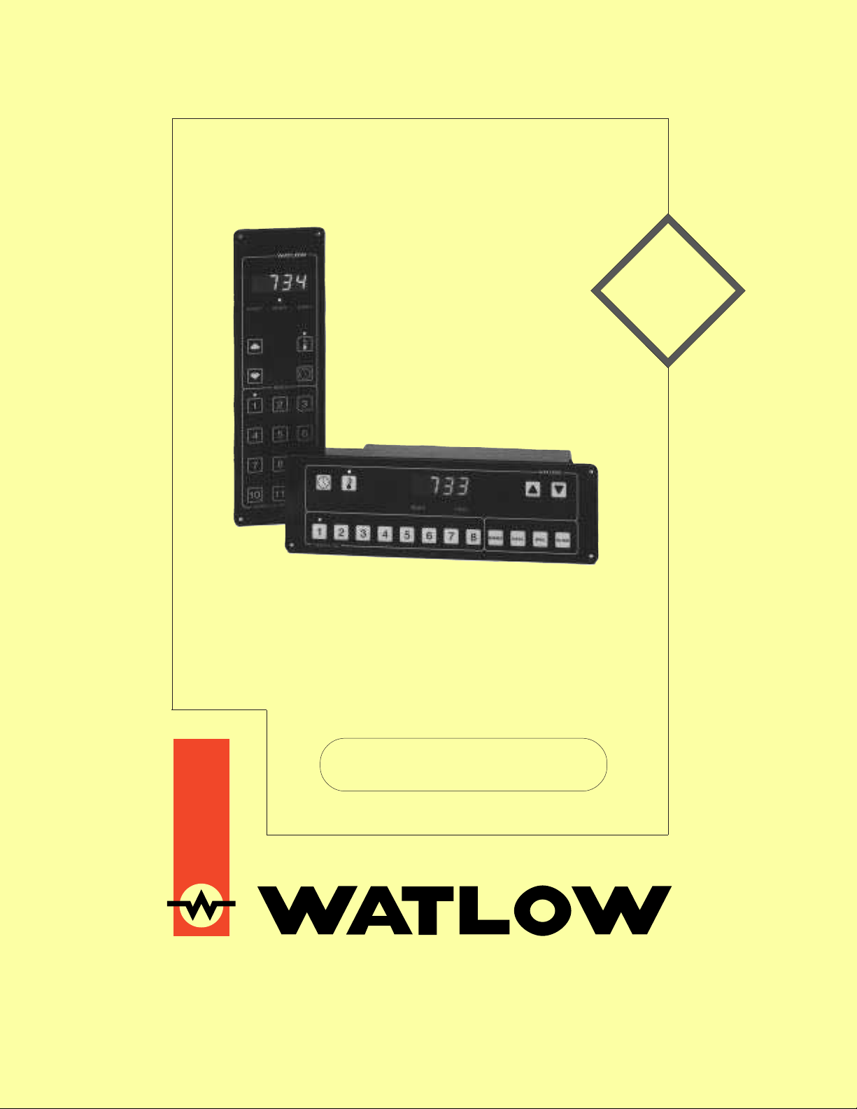
Series 733/734
Total
Customer
Satisfaction
3 Year
Warranty
Time/Temperature
Control
Service Manual
Watlow Controls, 1241 Bundy Blvd., P.O. BOX 5580, Winona, MN 55987-5580, Phone: 507/454-5300, Fax: 507/452-4507
0600-0008-0000 Rev D
November 1995
Supersedes without change: W733-XSMN Rev D00
$10.00
Made in the U.S.A.
Page 2

Contents
This manual is a supplement to the Series 733/734 Program Manual. It is for
configuring, servicing and calibrating your control. Use this manual in conjunc-
tion with the Series 733/734 Program Manual and Data Communications manual.
PageItem
Chapter 1
3 Install and Wire the Series 733/734
3 Dimensions
3 Panel Cutout
4 How to Wire the Series 733/734
5 Power Wiring
5 Input Wiring
8 Output 1 Wiring
9 Output 2 Wiring
10 Event Input Wiring
10 Event Output Wiring
10 Alarm Wiring
11 System Wiring Examples
Chapter 3
16 The Service Mode
17 Service Parameters
18 Service Mode Table
Chapter 4
20 Auto-Tuning
21 Manual Tuning
Chapter 5
22 The Calibration Mode
23 Calibration Parameters
24 Calibration Procedures
Chapter 2
12 The Setup Mode
12 Advancing Through the Setup Mode
12 Select or Change Setup Data Within the Mode
13 Setup Parameters
16 Setup ModeTable
Notes
˜
Informational notes alert you to important details.
When you see a note icon, look for an explanation in
the margin.
Safety Information
Boldface safety information protects both you and
your equipment. Please be attentive to them. Here
are explanations:
ç
The CAUTION symbol (exclamation point) in the wide
text column alerts you to a "CAUTION," a safety or
functional hazard which could affect
its performance. A full explanation is in the narrow
column on the outside of the page.
your equipment
or
∫
The WARNING symbol (lightning bolt) in the wide text
column alerts you to a "WARNING," a safety hazard
which could affect
explanation is in the narrow column on the outside of
the page.
you and the equipment
. A full
Appendix
30 Glossary
32 Index
33 Warranty/Returns
34 Specifications
35 Ordering Information
36 CE Declaration of Conformity
37 Notes
38 Notes
T echnical Assistance
If you encounter a problem with your Series 733/734
control, review all of your configuration information to
verify that your selections are consistent with your
application... Inputs, Outputs, Alarms, Limits, etc. If the
problem persists after checking the above, you can get
technical assistance by dialing: 1-507-454-5300
An Application Engineer will discuss your problem with
you. Please have the following information available:
• Complete model number • Revision number
• All configuration information • User's manual
The model and serial numbers can be found on the
outside of the case.
Your Feedback
Your comments or suggestions on the manual are
welcome, please send them to: Technical Writer, Watlow
Controls, 1241 Bundy Blvd., P.O. Box 5580, Winona, MN
55987-5580, or phone 507/454-5300. The Watlow Series
733/734 Service Manual and integral software are
copyrighted by Watlow Winona, Inc., © 1995, with all
rights reserved.
2
WATLOW Series 733/734 Service Manual
Install & Wire, Chapter 1
Page 3
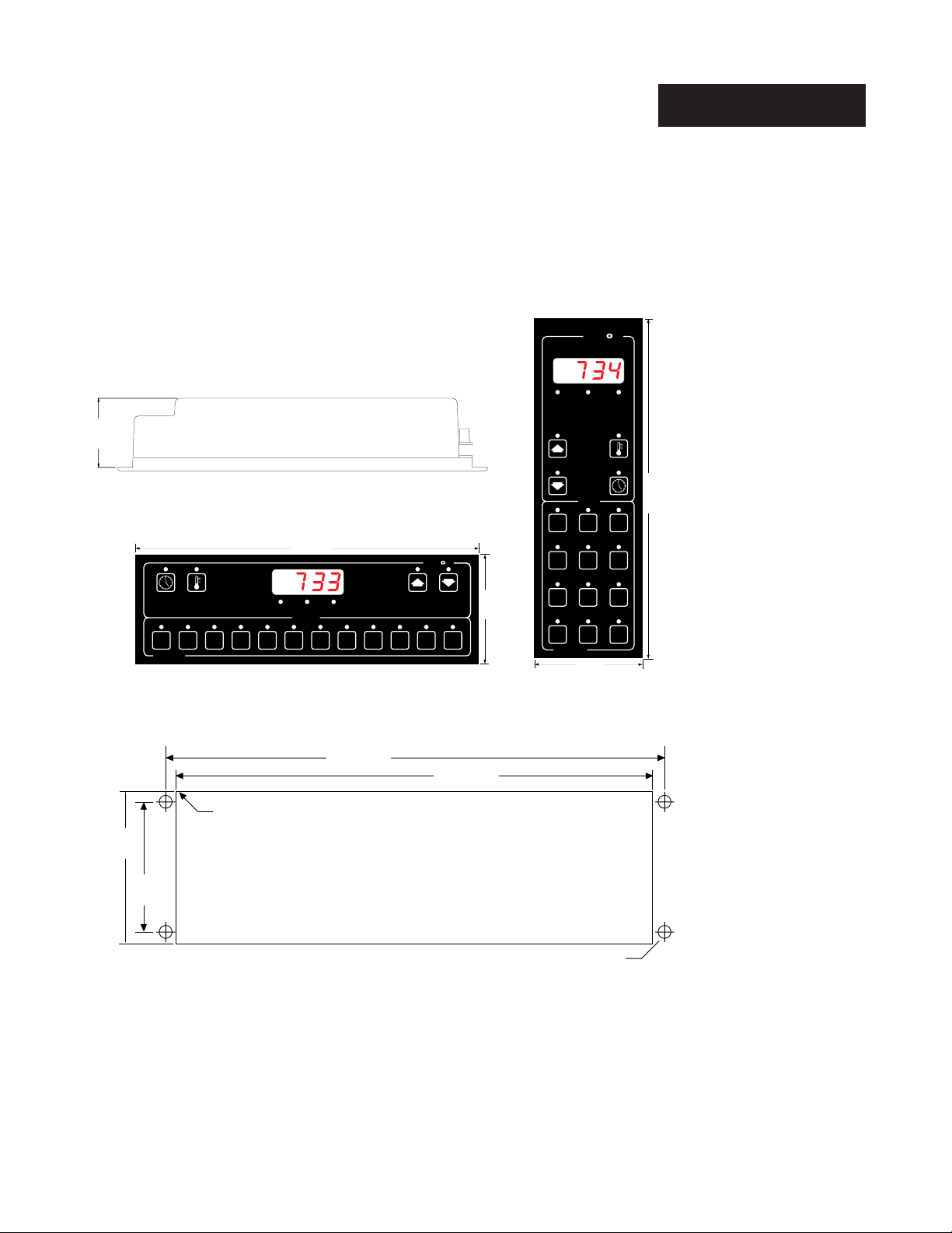
Chapter 1 Install and Wire the Series 733/734
Front panel mounting for ease of installation and service.
W
A
TL
W
Install
1.975
(50 mm)
(80 mm)
3.13"
2 4 6 7 9 11
1 3 5
SERIES 733
Series 733
R 0.125"
(3 mm) Max.
2.75"
(70 mm)
EVENT
10.625"
(270 mm)
LOAD 1READY
MENUS
81012
10.13"
(257 mm)
Panel Cutout
A
W
W
TL
(248 mm)
9.78"
˜
3.25"
(83 mm)
EVENT
READY LOAD 1
MENUS
1
2
3
4
5
6
8
11
3.25"
(83 mm)
9
12
7
10
SERIES 734
Series 734
10.625"
(270 mm)
Figure 1 Series 733 and 734
Dimensions.
Figure 2 Panel Cutout.
Use four #6-32 screws
Use four #6-32 screws
with press-in-nuts
with nutserts
(customer supplied)
(customer supplied)
0.27" Dia.
(7 mm)
1. Make a panel cutout per the dimensions given above.
2. Drill four 0.265 (7mm) diameter holes per the dimensions given above..
See Figure 2.
3. Mount the Series 733 or 734 with four #6-32 screws using press-in-nuts,
weld nuts, or equivalent…
Install & Wire, Chapter 1
WATLOW Series 733/734 Service Manual
˜
NOTE:
For Series 734
orientation (vertical), rotate the panel
cutout 90°.
3
Page 4
Wiring
How to Wire the Series 733/734
The Series 733/734 wiring is illustrated by model number option. Check the
terminal designation sticker on the control and compare your model number to
those shown here and also the model number breakdown on the inside back
cover of this manual.
When you apply power without sensor inputs on the terminal strip, the Series
733/734 display alternates parameter data and Er07 at a 3 second rate.
This error indicates an open sensor or A/D error. Remove power to the control
and connect the sensor properly. All wiring and fusing must conform to the
National Electric Code and to any locally applicable codes as well.
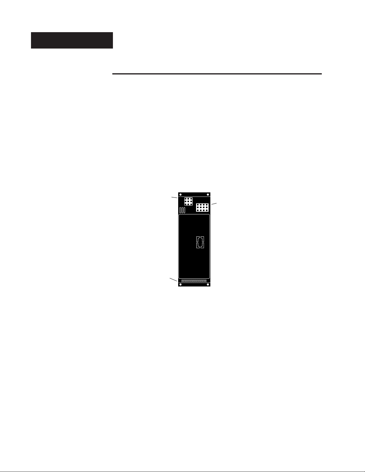
Use Figure 6 as a location reference when wiring your unit.
Figure 6 Series 733/734
Rear View.
9-pin
Event Input/
Output
Connector
Input/
Communications
Connector
12-pin
Output Wiring
Connector
4
WATLOW Series 733/734 Service Manual
Install & Wire, Chapter 1
Page 5
1234567891011
12
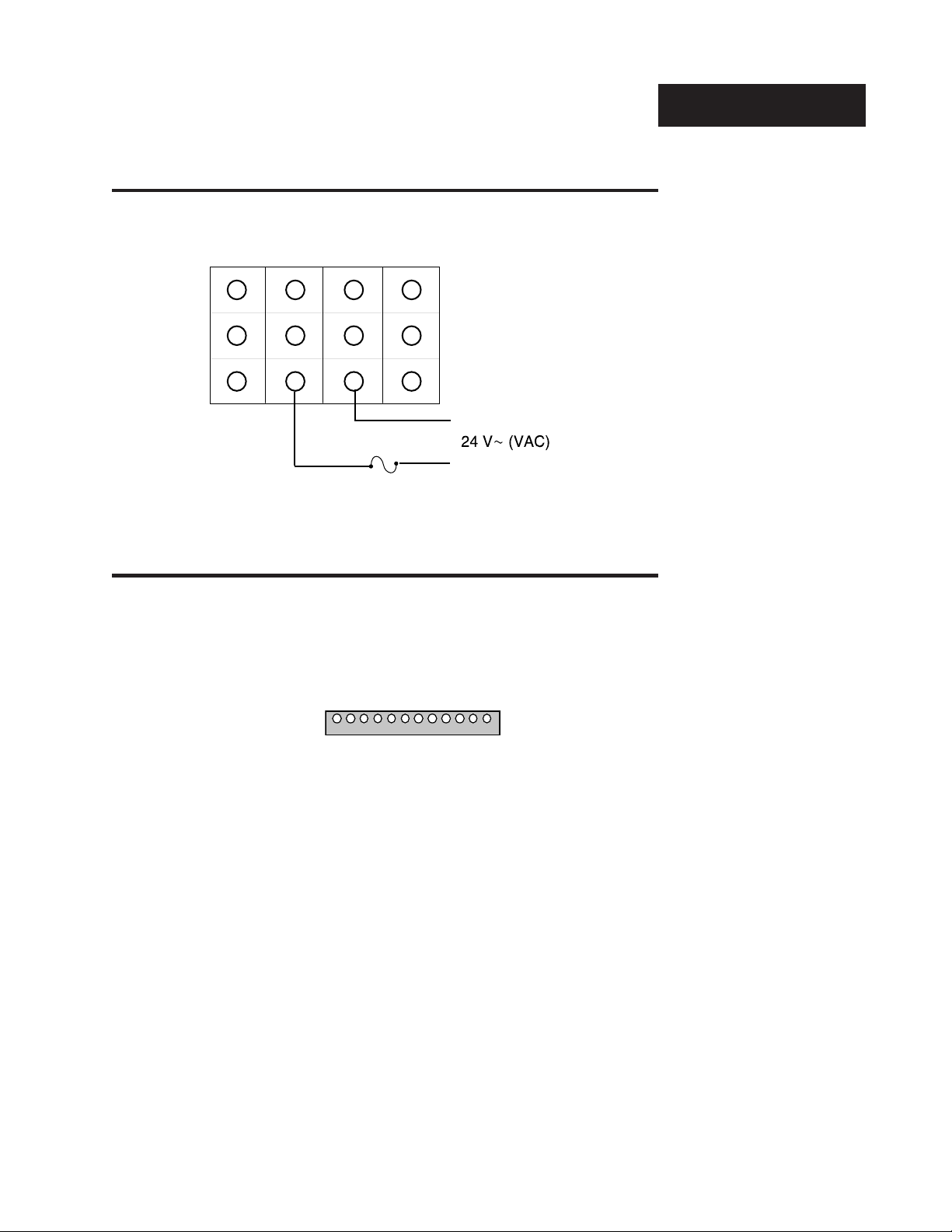
Power Wiring
Wiring
Figure 7 -
ÅÅ
24V
Å (VAC) Power
ÅÅ
10
1
2
4
5
7
8
11
Wiring.
3
6
9
12
L2
Fuse
L1
Input Wiring
Use this wiring connector as a reference for terminal orientation. Each individual wiring breakdown will only show the terminals used. This connector
only applies to input wiring and communications wiring.
∫
WARNING:
To avoid potential
electric shock, use
National Electric
Code (NEC) safety
practices when
wiring and connecting this unit to a
power source and to
electrical sensors or
peripheral devices.
Figure 8 Input Wiring Connector.
´ç
CAUTION:
Input power limited
to 15 watts maximum. All components are rated for a
maximum of 15
watts.
Install & Wire, Chapter 1
WATLOW Series 733/734 Service Manual
5
Page 6

Input Wiring
˜
NOTE:
Dual-zone thermocouple units require
at least one ungrounded
thermocouple.
Thermocouple Input
73XX-1XXX-XXXX ˜(Dual Zone Only)
73XX-4XXX-XXXX
73XX-6XXX-XXXX 73XX-4XXX-XXXX
Zone 1 Zone 2
1
4
Figure 9 Thermocouple
Wiring.
2
3
+
-
5
6
RTD Input
(Dual Zone Only)
73XX-2XXX-XXXX
73XX-5XXX-XXXX 73XX-5XXX-XXXX
Zone 1 Zone 2
3 Wire RTD
1
2
3 Wire RTD
4
5
+
-
Figure 10 2 or 3 Wire RTD
Wiring.
6
WATLOW Series 733/734 Service Manual
3
1
2
3
2 Wire RTD
6
4
5
6
2 Wire RTD
Install & Wire, Chapter 1
Page 7
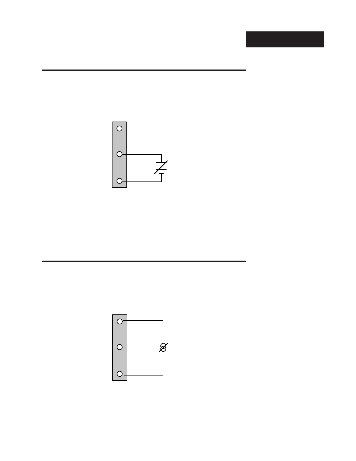
0-5VDC or 0-10VDC Process Input
Model # 73XX-6XXX-XXXX (Dual Zone Only)
Input Wiring
Zone 2
4
5
6
+
-
0-20mA or 4-20mA Process Input
Model # 73XX-6XXX-XXXX (Dual Zone Only)
Figure 11 0-5VDC or 0-10VDC
Process Input
Wiring.
Install & Wire, Chapter 1
Zone 2
4
5
6
-
Figure 12 -
DC
I
+
WATLOW Series 733/734 Service Manual
0-20mA or 4-20mA
Process Input
Wiring.
7
Page 8
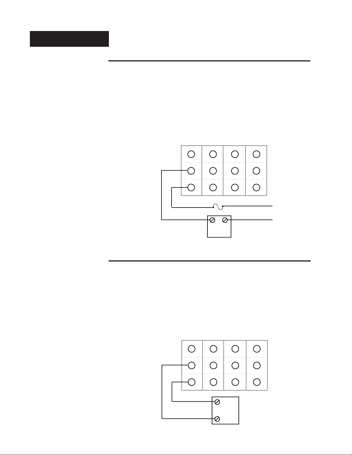
Output 1 Wiring
AC Output Wiring - Zone 1
Figure 13 AC Output 1 Wiring.
Solid State Relay
with
Mechanical Relay
with
Contact Suppression Contact Suppression
Form A, 0.4 Amps Form A, 1 Amp
Off state impedance: 20K max. Off state impedance: 20K min.
73XX-XBXX-XXXX 73XX-XDXX-XXXX
Solid State Relay
without
Solid State Relay
without
Contact Suppression Contact Suppression
Form A, 0.4Amps Form A, 1 Amp
Off state impedance: 31M max. Off state impedance: 20k max.
73XX-XKXX-XXXX 73XX-XEXX-XXXX
10
7
8
11
9
12
L1
COM
1
2
3
4
5
6
Fuse
L2
External
Load
Figure 14 DC Output 1 Wiring.
DC Output Wiring - Zone 1
Switched DC
(Open Collector) 4-20mA Process Output
Non-isolated Non-isolated
Minimum load resistance: 500 Load impedance: 600 max.
73XX-XCXX-XXXX 73XX-XFXX-XXXX
ÅÅ
0-5V
Å (VDC) Process Output
ÅÅ
Non-isolated
Load impedance: 10K min.
73XX-XHXX-XXXX
10
1
-
+
2
3
4
5
6
+
External
Load
-
7
8
11
9
12
8
WATLOW Series 733/734 Service Manual
Install & Wire, Chapter 1
Page 9

AC Output Wiring - Zone 2
Output 2 Wiring
Solid State Relay
with
Mechanical Relay
with
Contact Suppression Contact Suppression
Form A, 0.4 Amps Form A, 1 Amp
Off state impedance: 20K max. Off state impedance: 20K min.
73XX-XXBX-XXXX 73XX-XXDX-XXXX
Solid State Relay
without
Contact Suppression
Form A, 04 Amps
Off state impedance: 31M max.
73XX-XXKX-XXXX
NO
1
2
3
External
COM
4
Load
5
6
Fuse
7
8
11
9
12
L2
L1
10
Figure 15 AC Output 2 Wiring.
DC Output Wiring - Zone 2
Switched DC
(Open Collector) 4-20mA Process Output
Non-isolated Non-isolated
Minimum load resistance: 500 Load impedance: 600 max.
73XX-XXCX-XXXX 73XX-XXFX-XXXX
ÎÎ
0-5V
Î (VDC) Process Output
ÎÎ
Non-isolated
Load impedance: 10K min.
73XX-XXHX-XXXX
+
External
Load
-
+
-
10
1
2
3
4
5
6
7
8
11
9
12
Figure 16 DC Output 2 Wiring.
Install & Wire, Chapter 1
WATLOW Series 733/734 Service Manual
9
Page 10
Optional Wiring
1
23
4
5
6
7
89
Event 1
Event 2
Event 3
Event 4
-
-
-
-
+
Internal +5 Volt
SSR
Customer Supplied
+
+
+
SSR
SSR
SSR
Alarm
+
-
˜
NOTE:
Event Input is not
available on standard Series 733/734
controls. Consult
factory for more
information.
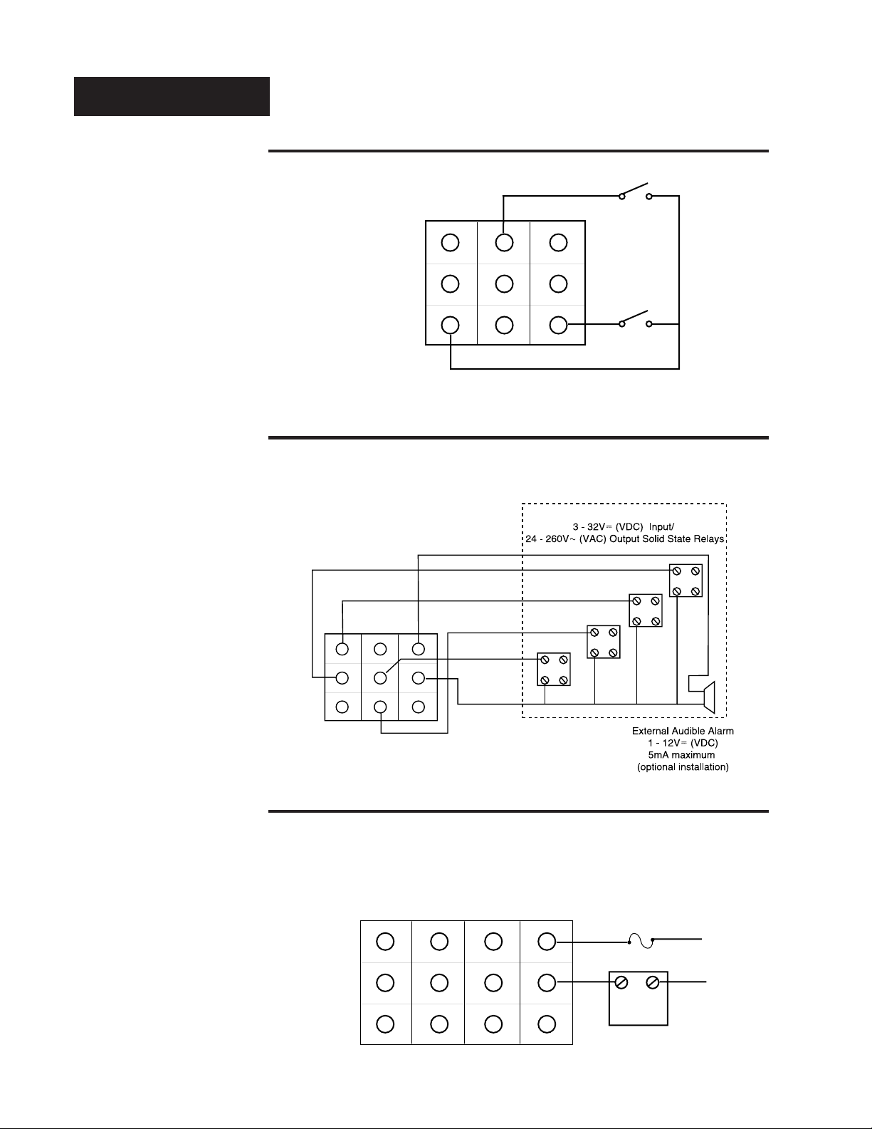
Event Input Wiring
2 Event Inputs
Non-isolated
73XX-XXX1-XXXX
Event Input 1
4
1
5
23
7
89
Figure 17 Event Input Wiring.
Figure 18 Event Output
Wiring.
Event Output Wiring
4 Event Outputs
Open Collector, Non-isolated
5mA Maximum Per Event
73XX-XXX1-XXXX
6
Event Input 2
Common
Alarm Wiring
Single Alarm
Mechanical Relay with
Contact Suppression
Form A, 1 Amp
Figure 19 -
10
Alarm Wiring.
WATLOW Series 733/734 Service Manual
73XX-XXXX-DXXX
1
2
3
4
5
6
7
8
11
9
12
COM
10
Fuse
L1
L2
External
Load
Install & Wire, Chapter 1
Page 11
L1
L2
A001-0249-0001
Over
Temp
Light
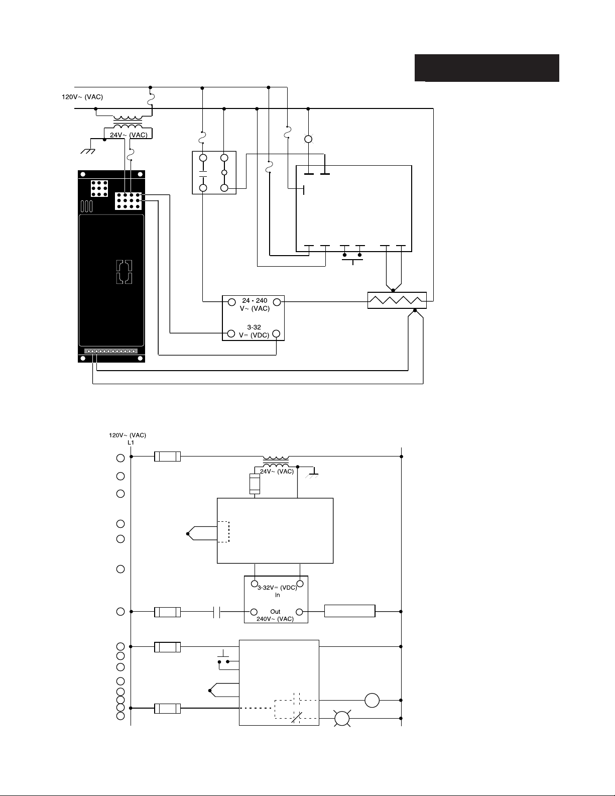
System Example
73XX-1CA0-AXXX
(-)
3
(+)
2
1
2
3
69
3
2
Coil
High Limit
Mechanical
Contactor
SSR-240-10G-DC1
(+)
NO
142A-36XX-1200
UL recognized
safety limit control
NC
C
Figure 20 System Wiring
TC
(+)
L1
ResetL2
Normally Open
Momentary
Switch
(-)
Limit
Sensor
(-)
Example.
Process Sensor
L2
1
3
4
6
69
A001-0249-0001
2
5
4
5
6
7
1
8
1 2
9
10
11
12
13
14
1
15
Install & Wire, Chapter 1
7
8
20
(+)
11
14
(-)
1 CR-1
2
3
73XX-1CA0-AXXX
910
(+)
12 13
L1 L2
15
Reset
16
COM
17
TC (+)
18
TC (-)
COM
Series 733
32
SSR-240-10G-DC1
(-)
Series 142
142A-36XX-1200
UL recognized
safety limit control
N.O.
N.C.
Heater
R
21
Hi Temp. Light
Figure 21 Series 733/734
Ladder Diagram
Example.
2
1CR
19
2
2
WATLOW Series 733/734 Service Manual
11
Page 12
Setup
t
d
0
F
e
e
t
e
m
e
w
h
s
w
t
e
w
h
s
w
h
e
t
e
y
h
e
u
)
)
)
)
)
)
)
)
)
)
)
)
)
)
Chapter 2 The Setup Mode
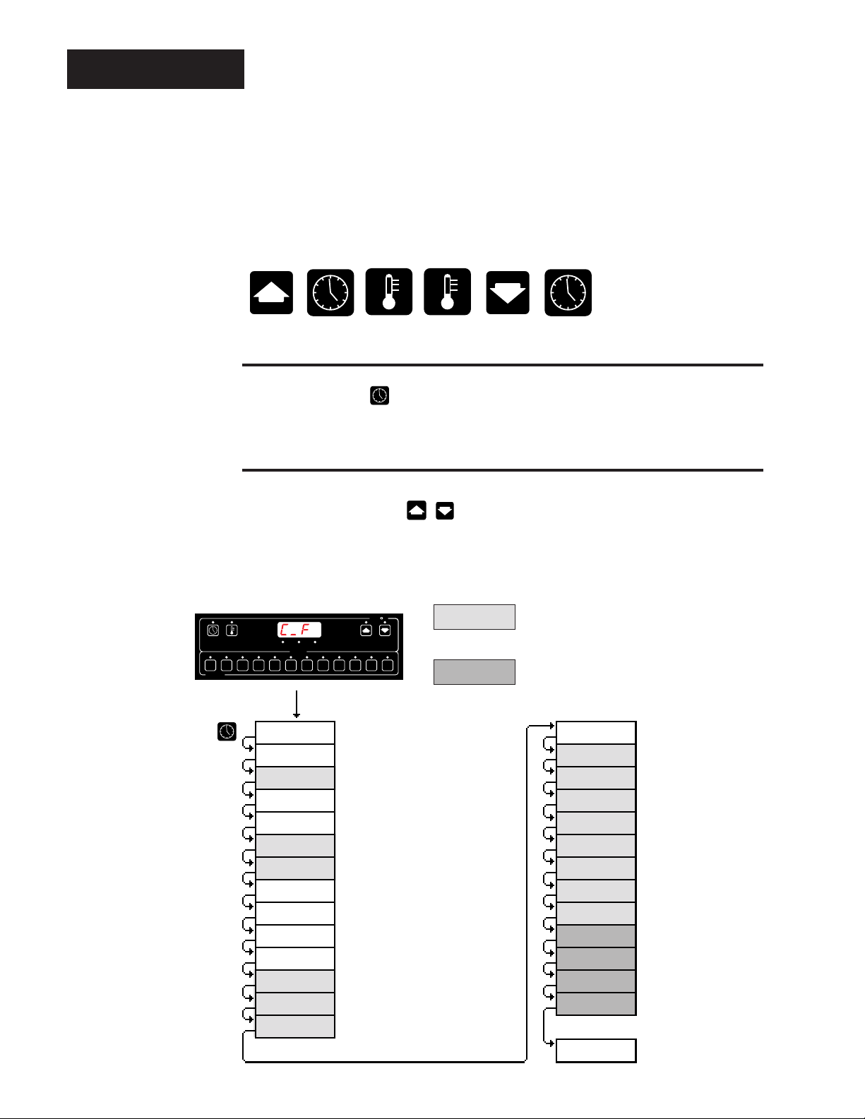
Use the key sequence below to enter the Setup Mode.
Advancing Through The Setup Mode
Press the TIME key .
Select or Change Setup Data Within The Mode
Figure 22 Setup Mode
Key Flow.
˜
NOTE:
Changing the
C_F, InP_, tS, rL_,
rH_ parameters
will default all
menus.
Use the UP/DOWN keys . After 1 minute with no key activactions, the
Series 733/734 reverts to the Operation mode [0)º0].
W
A
TL
SERIES 733
EVENT
C _
gb
rtd
tcnP
tS
SIL
LAt
InP1
rL1
rH1
HyS1
AL1
A1LO
A1HI
MENUS
W
LOAD 1READY
81012 1 3 5 2 4 6 7 9
(
(
(
(
(
(
(
(
(
(
(
(
(
(
11
Celsius_Fahrenhei
Guard ban
RTD calibration curv
Temperature comp. (WatCurv
Menu time selec
Alarm silenc
Latching for alar
Zone 1 input typ
Zone 1 range lo
Zone 1 range hig
Zone 1 hysteresi
Zone 1 alarm typ
Zone 1 alarm lo
Zone 1 alarm hig
= Parameter may not appear depending
on control configuration
= Only appears if your unit has communications.
See the Series 733/734 data communications
manual for more information.
CAL1
InP2
rL2
rH2
HyS2
AL2
A2LO
A2HI
CAL2
bAUd
dAtA
Prot
Addr
( )
( )
( )
( )
( )
( )
( )
( )
( )
( )
( )
( )
( )
00 : 0
Zone 1 calibration offse
Zone 2 input typ
Zone 2 range lo
Zone 2 range hig
Zone 2 hysteresi
Zone 2 alarm typ
Zone 2 alarm lo
Zone 2 alarm hig
Zone 2 calibration offse
Baud rat
Data bits and parit
Protocol type
Address
Operation Men
12
WATLOW Series 733/734 Service Manual
Setup Mode, Chapter 2
Page 13
Setup Parameters
Setup
Display alternates
between parameter and
programmed data.
Celsius_Fahrenheit: Selects the units of temperature measurement.
Range: F or C Default: F
Guard Band: Determines the process operating window (deviation) that both
Zone 1 & 2 must be within before a menu is allowed to run. If you are within the
guard band the READY LED is on and a menu can be run. It you are out of the
guard band, the READY LED is OFF and the menu will not run.
Range: 1 to 4000°F/2222°C Default: 4000°F/2222°C
RTD Calibration Curve: Selects the RTD calibration curve for RTD inputs.
Appears if InP1 = rtd for Zone 1, or InP2 = rtd for Zone 2. This parameter only
appears if you have a unit with RTD input.
JIS = 0.003916 / °C, DIN = 0.003850 / °C
Range: din or JIS Default: din
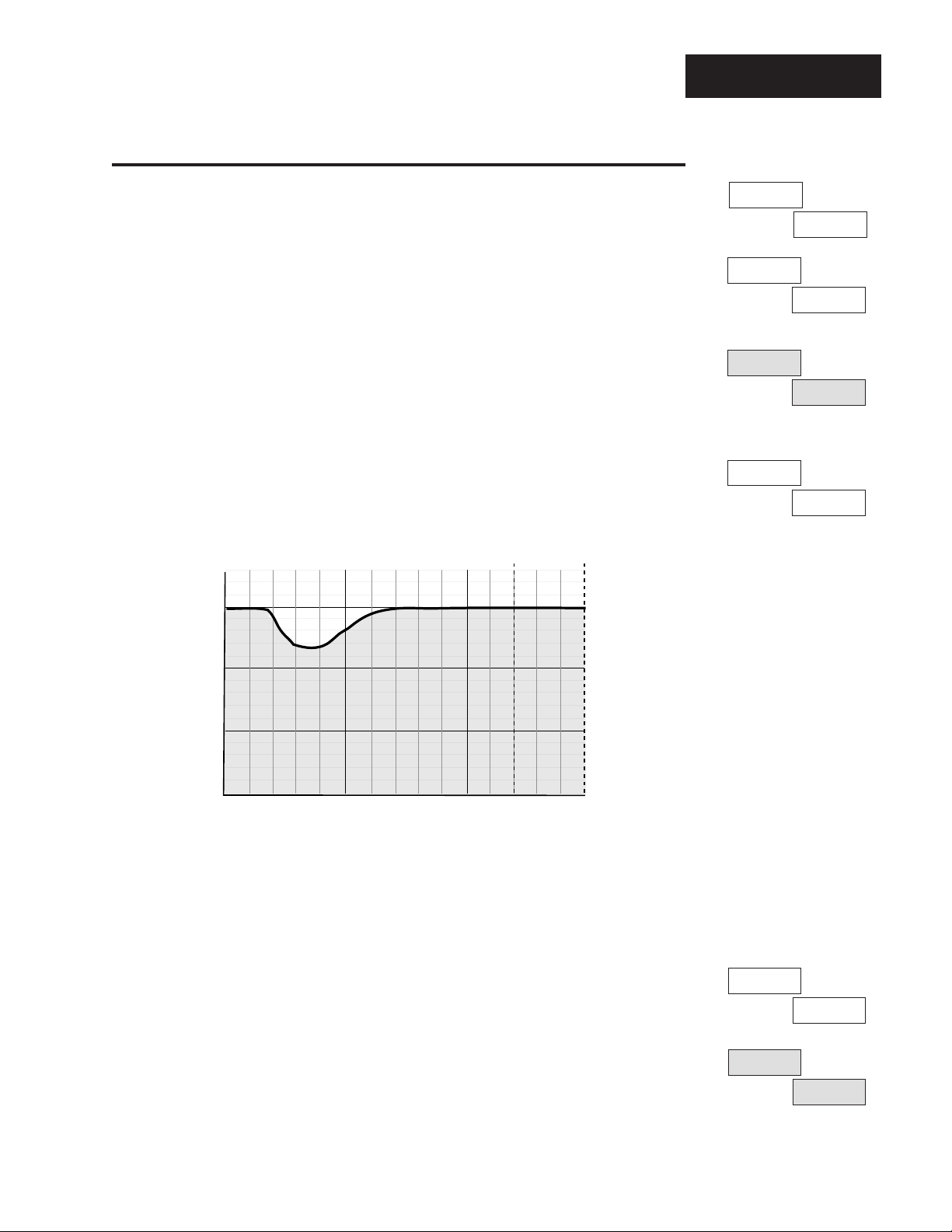
Temperature Compensation (WatCurve™): Automatically re-calculates and
adjusts a menu cooking time as a result of a disturbance — such as, opening the
oven door. WatCurve™ is a Watlow innovation. Enabled when tcnP = On.
Range: On or OFF Default: OFF
WatCurve™
Time
325°F/
°C
163°C
3 Minutes
C_F
F
gb
4000
rtd
din
tcnP
OFF
˜
NOTE:
Countdown time will
speed up or slow
down depending on
WatCurve™ algorithm .
Temperature
Time
In this example, a process is running at 325°F/163°C. A basket of french fries is
dropped into the oil, which dropped the process temperature to 240°F/116°C. The
fries normally take 3 minutes to cook, but since the temperature dropped, the
cooking time must be extended. WatCurve™ determines the amount of time which
must be added in relation to the drop in process temperature and the rate of rise.
Time Select: Selects the time base used for the menu time, and remaining time
for each zone. Can be expressed in either hours:minutes
or
minutes:seconds.
Range: hrnn or nnSc Default: nnSc
Alarm Silence: Enables or disables the alarm silence function. This parameter
only appears if your unit has alarms, and AL1 no and
AL2 no.
Range: On or OFF Default: OFF
Figure 23 WatCurve™
Example.
˜
NOTE:
All menus will have
the same time base
(hours/minutes, or
minutes/seconds).
tS
nnSc
SIL
OFF
Setup Mode, Chapter 2
WATLOW Series 733/734 Service Manual
13
Page 14

Setup
Display alternates
between parameter and
programmed data.
LAt
InP1
rL1
rH1
HYS1
nL
J
32
1382
3
Alarm Latching: Selects whether the alarm output is latching or non-latching.
This parameter only appears if your unit has alarms, and AL1 no and AL2 no.
Range: LA or nL Default: nL
Input Type 1: Selects the sensor input type for Zone 1. Only those input types
which are compatible with your unit will appear. See the model number information
on the inside back cover for your type.
Range: J, K (appears as H), E, rtd Default: J or rtd
Range Low 1: Selects the low end of the operating range for Zone 1. This
parameter determines the low end of the set point and alarms. See the model
number and specification information on the inside back cover, and Table 1 on
Page 14 for sensor range values.
Range: Sensor range low to rH1 Default: Low limit of sensor type
Range High 1: Selects the high end of the operating range for Zone 1. This
parameter determines the high end of the set point and alarms. See the model
number and specification information on the inside back cover, and Table 1 on
Page 14 for sensor range values.
Range: Sensor range high to rL1 Default: High limit of sensor type
Hysteresis 1: Selects the switching hysteresis for Zone 1 when Pb1 = 0 (ON/
OFF). See Page 17 for the Pb1 parameter.
Range: 1 to 99°F/1 to 55°C Default: 3°F
AL1
A1LO
A1HI
CAL1
InP2
Pr
32
1382
0
J
Alarm Type 1: Determines whether the alarm type for Zone 1 is process (Pr),
deviation (dE), or none (no). A process alarm is set at an absolute temperature. A
deviation alarm follows or tracks the set point. This parameter only appears if your
unit has alarms. Range: Pr, dE, no Default: Pr
Alarm 1 Low: Represents the low process alarm or low deviation alarm for Zone
1. This parameter only appears if your unit has alarms, and AL1 no.
If AL1 = dE: Range: 0 to -999°F/0 to -555°C Default: -999°F
If AL1 = Pr: Range: rL1 to A1HI Default: rL1
Alarm 1 High: Represents the high process alarm or high deviation alarm for
Zone 1. This parameter only appears if your unit has alarms, and AL1 no.
If AL1 = dE: Range: 0 to 999°F/0 to 555°C Default: 999°F
If AL1 = Pr: Range: A1LO to rH1 Default: rH1
Calibration Offset 1: Adds or subtracts degrees from the Zone 1 input signal.
Range: -99 to 99°F/-55 to 55°C Default: 0
Input Type 2: Selects the sensor input type for Zone 2. Only those input types
which are compatible with your unit will appear. This parameter only appears if you
have a dual zone control. See the model number information on the inside back
cover and Table 1 on Page 6 for your input type.
Range: J, K (appears as H), E or rtd or 0-5, 420, 010, 020
Default: J or rtd or 0-5
14
WATLOW Series 733/734 Service Manual
Setup Mode, Chapter 2
Page 15

Setup
Range Low 2: Selects the low end of the operating range for Zone 2. This parameter
determines the low end of the process input, set point and alarms. See the model
number and specification information on the inside back cover, and Table 1 below for
sensor range values. 0.0VDC, 0mA or 4mA represent Range Low (rL) for process
inputs and outputs. The process input is linearly scaled between rL and rH.
This parameter only appears if you have a dual zone control.
Range: Sensor range low to rH2 Default: Low limit of sensor type
Range High 2: Selects the high end of the operating range for Zone 2. This parameter
determines the high end of the process input, set point and alarms. 5.0VDC, 10.0VDC,
or 20mA represent Range High (rH2) for process inputs and outputs. The process input
is linearly scaled between rL and rH. This parameter only appears if you have a dual
zone control.
Range: Sensor range high to rL2 Default: High limit of sensor type
Hysteresis 2: Selects the switching hysteresis for Zone 2 when Pb2 = 0 (ON/OFF).
See Page 17 for the Pb2 parameter. This parameter only appears if you have a dual
zone control.
Range: 1 to 99°F/1 to 55°C/1 to 99 Units Default: 3°F
Alarm Type 2: Determines whether the alarm type for Zone 2 is process (Pr), deviation
(dE), or none (no). A process alarm is set at an absolute temperature. A deviation
alarm follows or tracks the set point. This parameter only appears if you have a dual
zone control and has alarms.
Range: Pr, dE, no Default: Pr
Display alternates
between parameter and
programmed data.
rL2
32
rH2
1382
HYS2
3
AL2
Pr
Alarm 2 Low: Represents the low process alarm or low deviation alarm for Zone 2.
This parameter only appears if you have a dual zone control, alarms, and AL2 no.
If AL2 = dE:
Range: 0 to -999°F/0 to -555°C/0 to -999 Units Default: -999°F
If AL2 = Pr:
Range: rL2 to A2HI Default: rL2
Alarm 2 High: Represents the high process alarm or high deviation alarm for Zone 2.
This parameter only appears if you have a dual zone control, alarms, and AL2 no.
If AL2 = dE:
Range: 0 to 999°F/0 to 555°C/0 to 999 Units Default: 999°F
If AL2 = Pr:
Range: A2LO to rH2 Default: rH2
Calibration Offset 2: Adds or subtracts degrees from the Zone 2 input signal. This
parameter only appears if you have a dual zone control.
Range: -99 to 99°F/-55 to 55°C/-99 to 99 Units Default: 0
Parameters that appear after CAL2 are related to data communications. For more
informaton see
Input Type Sensor Range Low Sensor Range High
J 32°F/0°C 1382°F/750°C
K (appears as H) 32°F/0°C 2282°F/1250°C
E 32°F/0°C 1220°F/660°C
rtd (1°) 32°F/0°C 1112°F/600°C
0-5 or 010 (VDC) -500 3500
020 or 420 (mA) -500 3500
How to Use Data Communications with the Watlow Series 733/734
A2LO
32
A2HI
1382
CAL2
0
.
Table 1 Input Ranges.
Setup Mode, Chapter 2
WATLOW Series 733/734 Service Manual
15
Page 16
Setup
Table 2 Setup Mode
Parameters and
Descriptions.
Setup Mode
Use this page as a master copy for your Series 733/734 Setup mode parameters.
Do not enter any values here; make photocopies instead.
Parameter Value Range Factory Default Appears If:
C_F C or F F
gb 1 to 4000°F/2222°C 4000°F/2222°C
rtd JIS or din din Input type is RTD
tncP On or OFF OFF
tS hrnn or nnSc nnSc
SIL On or OFF OFF Unit has alarms,
AL1 no & AL2 no
LAt LA or nL nL Unit has alarms,
AL1 no & AL2 no
InP1 J, K (appears as H), E or rtd J or rtd Dependent on model
number information
rL1 Sensor range low to rH1 Low limit sensor type
rH1 Sensor range high to rL1 High limit of sensor type
HYS1 1 to 99°F/1 to 55°C 3°F
AL1 Pr, dE or no Pr Unit has alarms
A1LO
A1HI
CAL1 -99 to 99°F/-55 to 55°C/-99 to 99Units 0
InP2 J, K (appears as H), E or J or rtd or 0-5 Dependent on model
rL2 Sensor range low to rH2 Low limit sensor type Hardware is present
rH2 Sensor range high to rL2 High limit of sensor type Hardware is present
HYS2 1 to 99°F/1 to 55°C/ 1 to 99 units 3°F Hardware is present
AL2 Pr, dE or no Pr Hardware is present
A2LO
A2HI
CAL2 -99 to 99°F/-55 to 55°C/-99 to 99Units 0 Hardware is present
If AL1 = dE:
0 to -555°C AL1 no
If AL1 = Pr:
If AL1 = dE:
0 to 555°C AL1 no
If AL1 = Pr:
rtd or 0-5, 420, 010, 020 number information
If AL2 = dE:
0 to -555°C/0 to -999 Units AL2 no
If AL2 = Pr:
If AL2 = dE:
0 to 555°C/0 to 999 Units AL2 no
If AL2 = Pr:
0 to -999°F/ -999°F Unit has alarms &
rL1 to A1HI rL1
0 to 999°F/ 999°F Unit has alarms &
A1LO to rH1 rH1
0 to -999°F/ -999°F Hardware is present &
rL2 to A2HI rL2
0 to 999°F/ 999°F Hardware is present &
A2LO to rH2 rH2
16
WATLOW Series 733/734 Service Manual
Setup Mode, Chapter 2
Page 17
Chapter 3
1
1
2
2
s
2
k
e
2
2
u
The Service Mode
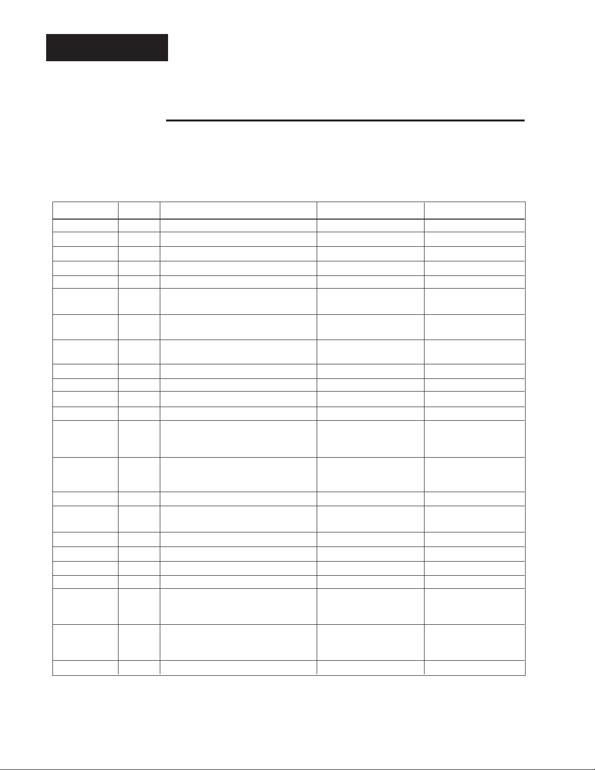
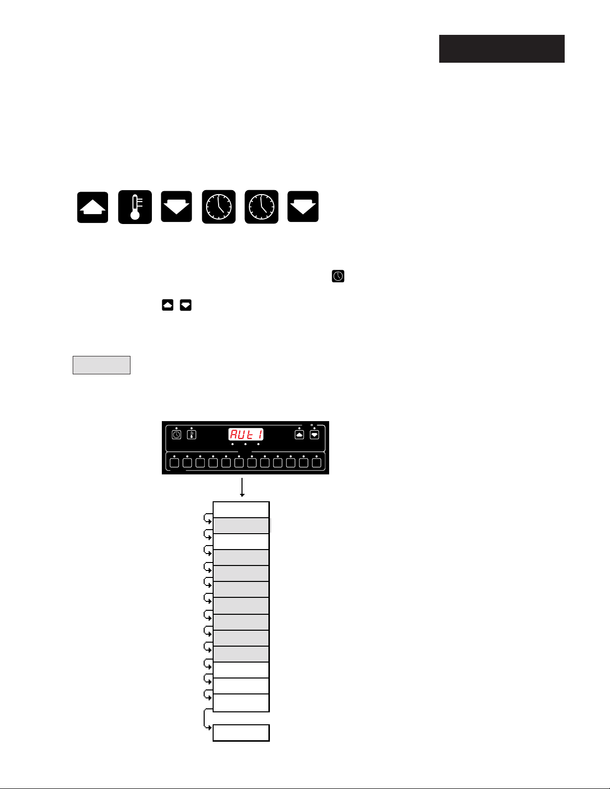
Enter the Service mode by pressing the key sequence illustrated below.
The display shows the [AUt1] parameter.
Move through the Service mode by pressing the TIME key .
Use the UP/DOWN keys to select data. After 1 minute without key activations, the Series 733/734 reverts to the Operation mode [0)º0].
Service
= Parameter may not appear depending
on control configuration
LOAD 1READY
EVENT
MENUS
2 4 6 7 9 11
1 3 5
SERIES 733
AUt1
AUt2
Pb1
rE1
rA1
Ct1
Pb2
rE2
rA2
Ct2
StP
LooP
nnS
81012
( )
( )
( )
( )
( )
( )
( )
( )
( )
( )
( )
( )
( )
W
A
TL
W
Auto-tune 1
Auto-tune
Proportional Band
Reset 1
Rate 1
Cycle time
Proportional band
Reset
Rate
Cycle time
Maximum step
Loop fail chec
Melt cycl
Figure 23 Service Mode
Key Flow.
0000
:
Service Mode, Chapter 3
Operation Men
WATLOW Series 733/734 Service Manual
17
Page 18

Service
Display alternates
between parameter and
programmed data.
AUt1
0
AUt2
0
Pb1
25
rE1
0.00
Service Parameters
Auto-tune Zone 1: Initiates auto-tune for Zone 1. For more information on tuning,
see Chapter 4, Page 19.
Range: 0 = off, 1 = slow, 2 = medium, 3 = fast Default: 0
Auto-tune Zone 2: Initiates auto-tune for Zone 2. For more information on tuning,
see Chapter 4, Page 19.
Range: 0 = off, 1 = slow, 2 = medium, 3 = fast Default: 0
Proportional Band 1: A proportional band expressed in degrees F or C, within
which a controller proportioning function is active for Zone 1. When Pb1 = 0, it
functions as an ON/OFF control. The switching differential is then determined by
the HYS1 parameter in the Setup mode. See Page 15.
Range: 0 to 999°F/0 to 555°C Default: 25°F
Reset 1: A reset (integral) control action for Zone 1 automatically eliminates offset,
or "droop," between set point and actual process temperature in a proportional
control. This parameter only appears if Pb1 0.
Range: 0.00 to 9.99 repeats/minute Default: 0.00
rA1
Ct1
Pb2
rE2
rA2
0.00
5
25
0.00
0.00
Rate 1: The rate (derivative) function for Zone 1 which affects the speed or rate at
which the process temperature approaches the set point to minimize overshoot
and/or undershoot. The rate is determined by how fast the error is changing. This
parameter only appears if Pb1 0.
Range: 0.00 to 9.99 minutes Default: 0.00
Cycle Time 1: Expressed in seconds, time for a controller to complete one ON/
OFF cycle for Zone 1. Time between successive turn ons. This parameter only
appears if Pb1 0.
Range: 1 to 60 seconds Default: 5
Proportional Band 2: A proportional band expressed in degrees or process units,
within which a controller proportioning function is active for Zone 2. When Pb2 = 0,
it functions as an ON/OFF control. The switching differential is then determined by
the HYS2 parameter. This parameter only appears if you have a dual zone control.
Range: 0 to 999°F/0 to 555°C/0 to 999 units Default: 25°F
Reset 2: A reset (integral) control action for Zone 2 automatically eliminates offset,
or "droop," between set point and actual process temperature in a proportional
control. This parameter only appears if your unit has a secondary output and Pb2
0.
Range: 0.00 to 9.99 repeats/minute Default: 0.00
Rate 2: The rate (derivative) function for Zone 2 which affects the speed or rate at
which the process temperature approaches the set point to minimize overshoot
and/or undershoot. The rate is determined by how fast the error is changing. This
parameter only appears if your unit has a secondary output and Pb2 0.
Range: 0.00 to 9.99 minutes Default: 0.00
18
WATLOW Series 733/734 Service Manual
Service Mode, Chapter 3
Page 19
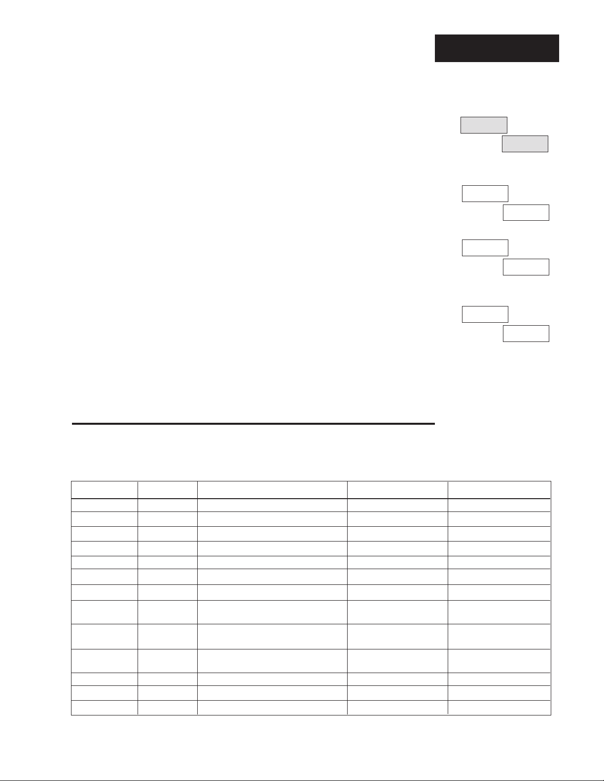
Service
Display alternates
between parameter and
programmed data.
Cycle Time 2: Expressed in seconds, time for a controller to complete one ON/
OFF cycle for Zone 2. Time between successive turn ons. This parameter only
appears if you have a dual zone control, and Pb2 0.
Range: 1 to 60 seconds Default: 5
Menu Steps: Determines the maximum number of steps allowed in a menu.
Range: 1 to 3 Default: 3
Loop Fail Check: This parameter checks for an open or shorted sensor and
enables the error code function. This parameter only functions in the proportional
control mode (Pb1 0 /ON/OFF).
Range: On or OFF Default: OFF
Melt Cycle: Enable or disables the melt cycle function. When enabled and the
process value is less than 212°F/100°C, the corresponding zone output will go to a
percent power duty cycle.
Range: On or OFF Default: OFF
Ct2
5
StP
3
LooP
OFF
nnS
OFF
Service Mode
Use this page as a master copy for your Series 733/734 Service mode parameters.
Table 3 Service Mode
Parameters and
Descriptions.
Do not enter any values here; make photocopies instead.
Parameter Value Range Factory Default Appears If:
AUt1 0 - 3 0
AUt2 0 - 3 0 Hardware is present
Pb1 0 to 999°F/0to 555·C 25°F
rE1 0.00 to 9.99 repeats/minute 0.00 Pb1 0
rA1 0.00 to 9.99 minutes 0.00 Pb1 0
Ct1 1 to 60 seconds 5 Pb1 0
Pb2 0 to 999°F/0 to 555°C/0 to 999 Units 25°F Hardware is present
rE2 0.00 to 9.99 repeats/minute 0.00 Hardware is present
Pb2 0
rA2 0.00 to 9.99 minutes 0.00 Hardware is present
Pb2 0
Ct2 1 to 60 seconds 5 Hardware is present
Pb2 0
StP 1 to 3 3
LooP On or OFF OFF
nnS On or OFF OFF
Service Mode, Chapter 3
WATLOW Series 733/734 Service Manual
19
Page 20
Tuning
˜
NOTE:
An X applies to
either Zone 1 or
Zone 2.
˜
NOTE:
In dual zone applications, allow Zone 1
to complete before
tuning Zone 2.
Chapter 4 Tuning
Auto-tuning
Auto-tuning applies to Zone 1 or 2.
The auto-tuning procedure operates on a thermal response value — slow,
medium, or fast. Use the slow thermal response when your process does not
reach set point too rapidly, or if it usually does not exceed set point a lot. A fast
thermal response produces a rapid temperature change over a short period of
time.
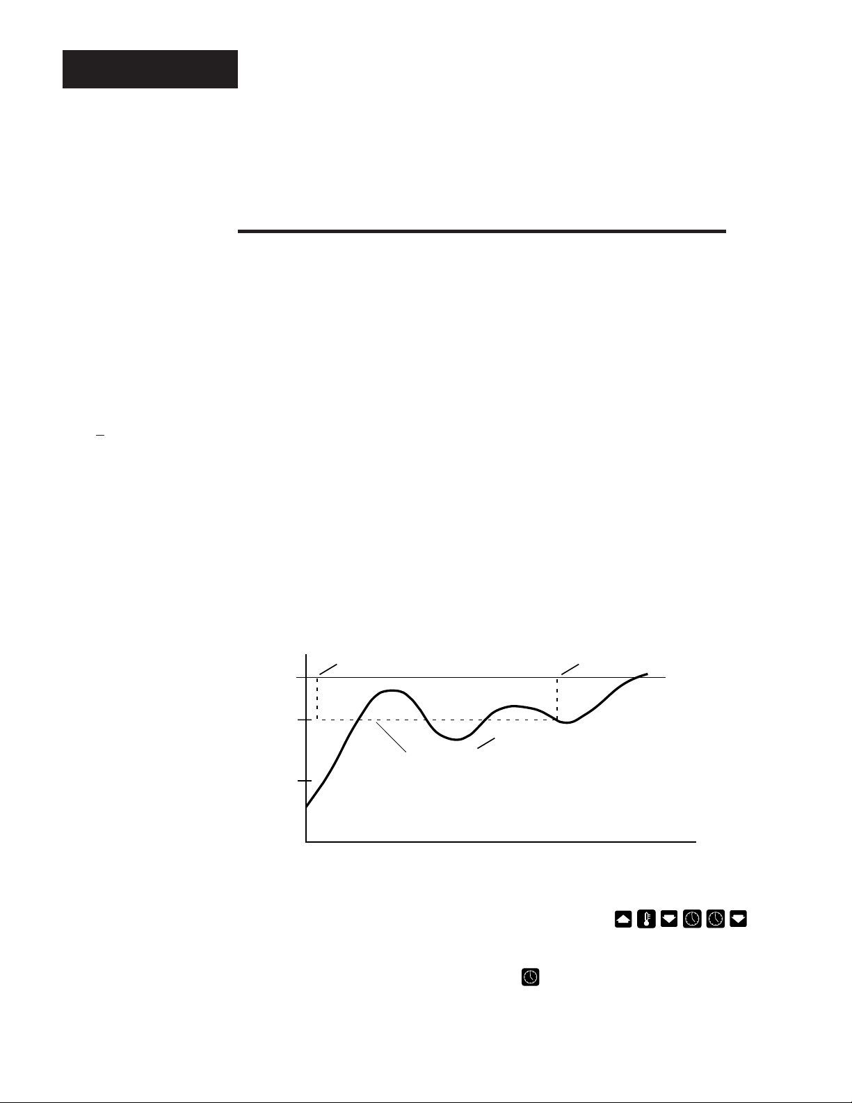
Once the auto-tune sequence has begun, the Zone 1 or 2 proportional band is
set to 0 and the control goes into an ON/OFF mode of control at 90% of the
established set point. The displayed set point remains unchanged. The
display alternates between At _ and the current parameter.
Once the control learns the thermal system response, it returns to a standard
PID control using the PID values automatically set as a result of auto-tuning.
Any change of the set point, while in auto-tune, re-initiates the auto-tune
procedure.
In order for the 733/734 to successfully complete auto-tune, the process must
cross the 90% value of set point four times within 80 minutes after auto-tune
has started. If this does not happen within the 80 minute time limit, the Pb
remains at 0 and the control functions in an ON/OFF mode.
Figure 24 Auto-tuning at a Set
Point of 200°F.
Auto-tune
Begins
200
180
Process
°Temp
100
To start auto-tuning:
1. Enter the Service mode by pressing the key sequence .
[AUt1] appears in the display.
To auto-tune Zone 2, press the Time key and [AUt2] appears.
90% of
Set Point
°Time
Auto-tune
Complete
Set Point
20
WATLOW Series 733/734 Service Manual
Tuning, Chapter 4
Page 21

2. Select a thermal response value using the UP/DOWN keys, 1=slow, 2=me-
dium, and 3=fast. A thermal response value of 2 satisfactorily tunes most
thermal systems.
3. When tuning is complete, the display returns to its previous state and AUtX
reverts to 0. The 733/734 installed appropriate PID tuning parameters and
saved them in the non-volatile memory. If a mechanical relay or contactor
is switching power to the load, a longer cycle time may be desirable to
minimize wear on the mechanical components. Typical life of a mechanical relay is 100,000 cycles at rated load.
To abort auto-tuning, the operator must reset the AUtX parameter to 0, or cycle
power off and on, or enter the Calibration mode. In all cases, aborting auto-tune
restores all values to those previous to auto-tuning.
Manual Tuning
For optimum control performance, tune the Series 733/734 to your thermal system.
The tuning settings here are for a broad spectrum of applications; your system may
have somewhat different requirements. NOTE: This is a slow procedure, taking
from minutes to hours to obtain optimum values.
1. Apply power to the Series 733/734 and enter a set point. Begin with these
Service parameters: Pb = 1, rE = 0.00, rA= 0.00, Ct = 5, CAL = 0, AUt= 0.
2. Proportional Band Adjustment : Gradually increase Pb until the displayed
temperature stabilizes to a constant value. The process temperature may not
be right on set point because the initial reset value is 0.00 repeats per minute.
Tuning
˜
NOTE:
Tune each zone at
a set point above
ambient temperature.
3. Reset Adjustment: Gradually increase rE until the displayed temperature
begins to oscillate or "hunt." Then slowly decrease rE until the temperature
stabilizes again near set point.
4. Cycle Time Adjustment: Set Ct as required. Faster cycle times sometimes
achieve the best system control. However, if a mechanical contactor or
solenoid is switching power to the load, a longer cycle time may be desirable to
minimize wear on the mechanical components. Experiment until the cycle time
is consistent with the quality of control you want. Ct does not effect units with a
process output.
5. Rate Adjustment: Increase rA to 1.00 minute. Raise set point by 20° to 30°F,
or 11° to 17°C, observe the system's approach to set point. If the load temperature overshoots set point, increase rA to 2.00 minutes.
Next raise set point by 20 to 30°F, or 11 to 17°C and watch the approach to the
new set point. If you increase rA too much, approach to set point will be very
sluggish. Repeat as necessary until the system rises to the new set point
without overshooting or approaching the set point too slowly.
6. Calibration Offset Adjustment: You may want your system to control to a
temperature other than the value coming from the input sensor. If so, measure
the difference between that temperature (perhaps at another point in the
system) and the process value showing in the display. Then enter the CAL
offset value you want. Calibration offset adds or subtracts degrees from the
value of the input signal.
Tuning, Chapter 4
WATLOW Series 733/734 Service Manual
21
Page 22
Calibration
Chapter 5 The Calibration Mode
Before attempting to calibrate, make sure you have the proper
equipment called for in each procedure.
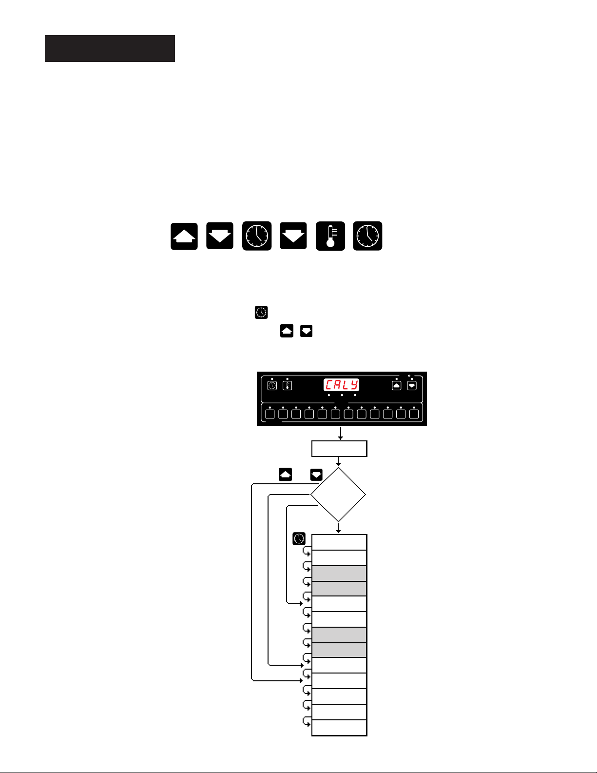
Use the key sequence below to enter the Calibration Mode.
In the Calibration Mode, various input signals must be supplied in order for the
control to go through its auto calibration.
Press the TIME key to advance through the Calabration Menu.
Use the UP/DOWN keys to change data. After 1 minute with no key
activactions, the Series 733/734 reverts to the Operation mode [0)º0].
Figure 25 Calibration Mode
Parameters.
˜
NOTE:
While in the Calibration Mode, all
control outputs are
OFF.
22
WATLOW Series 733/734 Service Manual
No
SERIES 733
rESt
or
Out
EVENT
CALy
All
InLO
InHI
nAHI
tC
Ot1L
Ot1H
Ot2L
Ot2H
rSt
LgOt
LI
HEy
dISP
MENUS
Yes
LOAD 1READY
81012 1 3 5 2 4 6 7 9 11
( )
( )
( )
( )
( )
( )
( )
( )
( )
( )
( )
( )
( )
( )
W
A
TL
W
Calibration, Chapter 5
Page 23
Before attempting to calibrate,
make sure you have the proper
equipment called for in each procedure.
The Series 733/734 is calibrated and tested
before leaving the factory.
Calibration Parameters
Calibration
ç
Calibrate: Determines which parameters, if any are to be calibrated. Choose one
of the options below:
ALL All parameters are calibrated. The next parameter is InLO.
OUt Only the process outputs are calibrated. The display skips to the Ot1L
parameter.
no No parameters are calibrated. The display skips to the LgOt parameter.
rESt Restores factory calibration parameters. See Page 26 for more
information.
Input Low: The low calibration point for each zone. Input 0.00mV uncompensated
for thermocouple and process units. Input 100 for RTD units.
Input High: The high calibration point for each zone. Input 50mV for single and
dual t/c versions, or input 317.33 for RTD units, or input 10V for dual input t/c and
process units on Zone 2.
mA Input High: Represents the high current calibration point for Zone 2, input
20mA. Applies only to thermocouple and process input. Only applies to Zone 2
inputs.
Thermocouple Compensator: Used to calibrate the thermocouple reference
compensator for units with thermocouple input. Input 0.00mV compensated
through Type J reference compensator (32°F/0°C).
CALy
InLO
InHI
nAHI
tC
4-20mA Output Low (Zone 1): Represents the process output low current calibration point for Zone 1. Applies to 0-5VDC and 4-20mA outputs only.
4-20mA Output High (Zone 1): Represents the process output high current
calibration point for Zone 1. Applies to 0-5VDC and 4-20mA outputs only.
4-20mA Output Low (Zone 2): Represents the process output low current calibration point for Zone 2. Applies to 0-5VDC and 4-20mA outputs only. This parameter
only appears if you have a dual zone control.
4-20mA Output High (Zone 2): Represents the process output high current
calibration point for Zone 2. Applies to 0-5VDC and 4-20mA outputs only. This
parameter only appears if you have a dual zone unit.
Calibration, Chapter 5
WATLOW Series 733/734 Service Manual
Ot1L
Ot1H
Ot2L
Ot2H
23
Page 24
Calibration
rSt
LgOt
LI
HEy
dISP
Restore : Restores factory calibration parameters. See below for more information.
Logic Output Test: Used to test all the control and logic outputs.
0 = All outputs OFF 1 = Output #1 ON
2 = Output #2 ON 3 = Alarm ON
4 = Event #1 ON 5 = Event #2 ON
6 = Event #3 ON 7 = Event #4 ON
8 = Audible output ON
Logic Inputs: This parameter reads all the board option jumpers and the event
inputs. Factory use only.
Keyboard: Used to read all the keys in hexadecimal.
Display Test: Performs a display test. A sequence of characters will move across
the seven-segment displays and LED's. This parameter will continue until you
advance.
Restoring Factory Calibration
The rSt parameter restores the factory calibration values to the Series 733/734. If
you calibrate your control incorrectly, you have the option to default to the original
values. Once you leave the CAL menu, the values are entered.
1. Enter the Calibration mode by using the key sequence .
2. [CALY] appears. Press the Up key until the [rESt] parameter appears.
3. Press the Time key , the [`rSt] parameter is displayed.
4. Press the Up key once and [`YES] will appear. Press the Time key .
5. The Series 733/734 will beep and advance to the [LgOt] parameter.
This procedure is only to be used to restore calibration. It is not meant to
default any other values.
24
WATLOW Series 733/734 Service Manual
Calibration, Chapter 5
Page 25

Thermocouple Field Calibration Procedure
(Single & Dual Thermocouple Only)
For model #'s: 73XX-1XXX-XXXX 73XX-4XXX-XXXX
Equipment Required:
• Type "J" Reference Compensator with reference junction at 32°F/0°C
Type "J" Thermocouple Calibrator set at 32°F/0°C.
• Precision millivolt source, 0-50mV min. range, 0.01mV resolution
Two millivolt sources and two compensators OR two thermocouple calibrators are
required
for dual zone controls.
Setup And Calibration ˜
1. Connect the AC line voltage L1 and L2 to the proper terminals.
2. For Zone 1, connect the millivolt source to Terminal #2 Positive and Terminal #3
Negative on the Series 733/734 terminal strip. Use regular 20-24 gauge wire.
For Zone 2, connect the millivolt source to Terminal #5 Positive and Terminal #6
Negative on the Series 733/734 terminal strip. Use regular 20-24 gauge wire.
˜
3. Apply power to the unit and allow it to warm up for 15 minutes. After warm-up
put the unit in the CAL menu. See the beginning of this chapter.
4. At the CALy parameter, select ALL. At the InLO prompt, enter 0.00 mV from the
millivolt source to the control for each zone. Allow at least 10 seconds to
stabilize. Press the TIme key.
5. At the InHI prompt, enter 50.0mV from the millivolt source, for each zone. Allow
at least 10 seconds to stabilize. Press the Time key.
T/C Calibration
Calibration
OR
˜
NOTE:
Before calibration
on an installed
control, make sure
all data and parameters are documented. See Setup,
and Service Tables,
Pages16 and 19.
˜
NOTE:
Always press the
Time key to advance
to the next parameter before changing the calibration
equipment.
6. At the tc prompt, disconnect the millivolt source, and connect the reference
compensator or t/c calibrator to Terminal #2 Positive, and Terminal #3 Negative
for Zone 1, and to Terminal #5 Positive and Terminal #6 Negative for Zone 2. If
using a compensator, turn on and short the input wires. If using "J" calibrator,
set to simulate 32°F/0°C. Allow 10 seconds for the control to stabilize.
To conclude the t/c calibration, press the Time key to advance through the
Calibration mode. To continue calibrating your outputs, press the Time key
once. The unit will leave the Calibration mode if 1 minute passes between key
activations and retains all changed values.
Calibration, Chapter 5
WATLOW Series 733/734 Service Manual
25
Page 26

RTD Calibration
RTD Field Calibration Procedure
(Single & Dual RTD Only)
For model #'s: 73XX-2XXX-XXXX 73XX-5XXX-XXXX
˜
NOTE:
Before calibration
on an installed
control, make sure
all data and parameters are documented. See Setup,
and Service Tables,
Pages16
and 19.
˜
NOTE:
Always press the
Time key to advance
to the next parameter before changing the calibration
equipment.
Equipment Required:
• 1K precision decade resistance box with 0.01 resolution. For dual zone
units, two decade boxes are reqiured.
Setup And Calibration ˜
1. Connect the AC line voltage L1 and L2 to the proper terminals.
2. Connect the decade resistance box to Terminal #1, 2 and 3 for Zone 1. For
Zone 2 units connect the decade resistance box to Terminal #4, 5, 6 on the
terminal strip. Use regular 20 - 24 gauge wire of the same length and type.
˜
3. Apply power to the unit and allow it to warm up for 15 minutes. After warmup put the unit in the Calibration mode. See the beginning of this chapter.
4. At the CALy parameter, select ALL. Press the Time key. At the InLO
prompt, set the decade resistance box to 100.0. Allow at least 10 seconds to
stabilize. Press the Time key.
5. At the InHI prompt, set the decade resistance box to 317.33. Allow at least 10
seconds to stabilize. Press the Time key.
To conclude the RTD calibration, press the Time key to advance through the
Calibration mode. To continue calibrating your outputs, press the Time key
once. The unit will leave the Calibration mode if 1 minute passes between key
activations and retains all changed values.
26
WATLOW Series 733/734 Service Manual
Calibration, Chapter 5
Page 27

Thermocouple/Process Input Field Calibration Procedure
For model #: 73XX-6XXXX-XXXX
Equipment Needed
• Type "J" Reference Compensator with reference junction at 32°F/0°C
Type "J" Thermocouple Calibrator set at 32°F/0°C.
• Precision millivolt source, 0-50mV min. range, 0.01mV resolution
• Precision voltage source 0-10 volt minimum range with 0.001 volt resolution.
• Precision current source 0 - 20mA minimum range with 0.001 volt resolution.
Setup And Calibration ˜
1. Connect the AC line voltage L1 and L2 to the proper terminals.
2. For Zone 1, connect the millivolt source to Terminal #2 Positive and Terminal #3
Negative on the Series 733/734 terminal strip. Use regular 20-24 gauge wire.
For Zone 2, connect the voltage source to Terminal #5 Positive and Terminal #6
Negative on the Series 733/734 terminal strip. Use regular 20-24 gauge wire.
3. Apply power to the unit and allow it to warm up for 15 minutes. After warm-up put
˜
the unit in the CAL menu. See the beginning of this chapter.
4. At the CALy parameter, select ALL. At the InLO prompt, enter 0.00 mV from the
millivolt source to the control for each zone. Allow at least 10 seconds to stabilize.
Press the TIme key.
5. At the InHI prompt, enter 50.0mV from the millivolt source for Zone 1. For Zone 2,
enter 10.00V from the voltage source. Allow at least 10 seconds to stabilize.
Press the Time key.
6. At the nAHI prompt, remove the voltage source from Zone 2. Connect the current
source to Terminal #6 Positive, and Terminal #4 Negative. Enter 20.00mA from
the current source. Allow at least 10 seconds to stabilize. Press the Time key.
OR
T/C-Process Input
˜
NOTE:
Before calibration
on an installed
control, make sure
all data and parameters are
documented. See
Setup and Service
Tables, Pages 16
and 19.
˜
NOTE:
Always press the
Time key to advance
to the next parameter before changing the calibration
equipment.
7. At the tc prompt, disconnect the millivolt source, and connect the reference
compensator or t/c calibrator to Terminal #2 Positive, and Terminal #3 Negative for
Zone 1. If using a compensator, turn on and short the input wires. If using "J"
calibrator, set to simulate 32°F/0°C. Allow 10 seconds for the control to stabilize.
To conclude the t/c calibration, press the Time key to advance through the
Calibration mode. To continue calibrating your outputs, press the Time key once.
The unit will leave the Calibration mode if 1 minute passes between key activations
and retains all changed values.
Calibration, Chapter 5
WATLOW Series 733/734 Service Manual
27
Page 28

4-20mA Output
The calibration procedure for Zone 1 and Zone 2 are the same
except use the Ot2L and Ot2H parameters for Zone 2.
Zone 1 4-20mA Output Field Calibration Procedure
For model #: 73XX-XFXX-XXXX 73XX-XXFX-XXXX
73XX-XFFX-XXXX
Equipment Required
• 300 , 1/2 watt 10% resistor. • 4 - 1/2 digit Digital Multimeter.
Setup And Calibration ˜
1. Connect the AC line voltage L1 and L2 to the proper terminals of the 733/734.
˜
NOTE:
Before calibration
on an installed
control, make sure
all data and parameters are documented. See Setup
and Service Tables,
Pages 16 and 19.
2. Connect the multimeter in series with the 300 resistor to Output connector
#2 Negative and #3 Positive for Zone 1.
3. Apply power to the unit and allow it to warm up for 15 minutes. After warm-up
put the unit in the Calibration mode. See the beginning of this chapter At the
CALy parameter, select OUt. Press the Time key.
4. At the Ot1L prompt, the multimeter should read approximately 4mA. Allow at
least 10 seconds to stabilize.
5. Use the Up/Down keys (reverse acting) to adjust the reading on the
multimeter for 3.85mA ± 0.10mA. Press the Time key.
6. At the Ot1H prompt, the multimeter should read approximately 20mA. Allow
at least 10 seconds to stabilize.
7. Use the Up/Down keys (reverse acting) to adjust the reading on the
multimeter for 20.15mA ±0.10 mA.
8. For dual 4-20mA output control, connect the multimeter in series with the
300 resistor to Output connector #4 Negative and #1 Positive. Use regular
20 - 24 gauge wire. Repeat steps 4 through 7 using the Ot2L and Ot2H
prompts.
28
WATLOW Series 733/734 Service Manual
Calibration, Chapter 5
Page 29

The calibration procedure for Zone 1 and Zone 2 are the same
except use the Ot2L and Ot2H parameters for Zone 2.
0-5V Output
Zone 1 0-5V
For model #'s: 73XX-XHXX-XXXX 73XX-XXHX-XXXX
Equipment Required
• 20K 1/4 watt 10% resistor. • 4 - 1/2 digit Digital Multimeter.
Setup And Calibration ˜
1. Connect the AC line voltage L1 and L2 to the proper terminals of the 733/734.
2. Connect the multimeter across the 20K resistor to Output connector #2
Negative and #3 Positive for Zone 1.
3. Apply power to the unit and allow it to warm up for 15 minutes. After warm-
up put the unit in the Calibration mode. See the beginning of this chapter At
the CALy parameter, select OUt. Press the Time key.
4. At the Ot1L prompt, the multimeter should read approximately 0V. Allow at
least 10 seconds to stabilize.
5. Use the Up/Down keys (reverse acting) to adjust the reading on the
multimeter for - 0.2 ± 0.1V. Press the Time key.
ÎÎ
Î (VDC) Output Field Calibration Procedure
ÎÎ
73XX-XHHX-XXXX
˜
NOTE:
Before calibration
on an installed
control, make sure
all data and parameters are documented. See Setup
and Service Tables,
Pages 16 and 19.
6. At the Ot1H prompt, the multimeter should read approximately 5V. Allow at
least 10 seconds to stabilize.
7. Use the Up/Down keys (reverse acting) to adjust the reading on the
multimeter for 5.2V ± 0.1V.
8. For dual 0-5V output control, connect the multimeter across the 20K resistor
to Output connector #4 Negative and #1 Positive. Use regular 20 - 24 gauge
wire. Repeat steps 4 through 7 using the Ot2L and Ot2H prompts.
Calibration, Chapter 5
WATLOW Series 733/734 Service Manual
29
Page 30

Glossary, A - I
Alarm: A condition, generated by a controller,
indicating that the process has exceeded or dropped
below a predetermined alarm set point.
Alarm Silence: Disables the alarm relay output.
Anti-reset: Control feature that inhibits automatic
reset action outside the proportional band. Also
known as "reset windup inhibit."
Automatic prompts: Data entry points where a
microprocessor-based control "prompts" or asks the
operator/programmer for information input.
Auto-tune: Automatically tunes the Series 733/
734PID parameters to fit the characteristics of your
particular thermal system.
Closed loop: Control system that has a sensing
device for process variable feedback.
Cold junction: Point of connection between thermocouple metals and the electronic instrument.
Cold junction compensation: Electronic means to
compensate for the ambient temperature at the cold
junction.
Combi-oven: Combination convection and steam
oven that cooks large amounts of food in substantially reduced time.
Conveyor Oven: Oven with a conveyor that passes
the food through it for a prescribed time. It may have
doors located along its length for adding food at
different points, thus varying cooking time for individual products.
Cook and Hold Oven: Slow cooker that cooks food
(typically large pieces of meat) over a period of
several hours at one temperature, and then holds the
food at another temperature.
Default parameters: The parameters permanently
stored in memory to provide a data base.
DIN: Deutsche Industrial Norms, a widely-recognized German standard for engineering units.
Droop: Difference in temperature between set point
and stabilized process temperature.
Duty cycle: Percentage of "load ON time" relative to
total cycle time.
Form A: Single Pole Single Throw relay that only
utilizes the N.O. and Common contacts. These
contacts close when the relay coil is energized. The
contacts open when power is removed from the
control.
Form B: Single Pole Single Throw relay that only
utilizes the N.C. and Common contacts. These
contacts will open when the relay coil is energized.
The contacts will close when power is removed from
the control.
Form C: Single Pole Double Throw. Utilizes the
N.O., N.C. and Common contacts. The user has the
option of wiring for a Form A or Form B contact. Refer to Form A & Form B above for more information.
Fryer: Fryers cook foods in hot oil.
Griddle: Flat cooking surface for cooking foods.
May be one-sided or have a top plate that is lowered
to cook food from both sides simultaneously/
Guard Band: A feature on a cooking control that
creates a temperature "window" around set point,
where you cannot start a menu. A guard band
prevents undercooking or overcooking.
Holding Cabinets: Cabinets to keep foods warm
and moist after they are cooked.
Cycle time: The time necessary to complete a full
ON-through-OFF period in a time proportioning
control system.
Deck Oven: Stackable, multiple chamber oven.
Derivative: Anticipatory action that senses the rate
of change of the process, and compensates to
minimize overshoot and undershoot. Also "rate."
Deviation alarm: An alarm referenced at a fixed
number of degrees, plus or minus, from set point.
30
WATLOW Series 733/734 Service Manual
Hysteresis: In ON/OFF control, the temperature
change necessary to change the output from full OFF
to full ON again.
Hunting: Oscillation or fluctuation of process
temperature about the set point.
Idle and Idle Exit: A feature in a restaurant fryer for
slow-use periods to run fryers at a lower temperature,
thus saving cooking oil and energy.
Input: Process variable information being supplied
to the instrument.
Appendix
Page 31

Integral: Control action that automatically eliminates
offset, or “droop,” between set point and actual
process temperature. Also "reset."
Glossary, I - Z
Isolation: Electrical separation of sensor or other
device from high voltage circuitry. Allows for application of grounded or ungrounded sensing element.
JIS Japanese Industrial Standards. Also Japanese
Industrial Standards Committee (JISC). Establishes
standards on equipment and components.
Melt Cycle: A fryer feature for melting congealed oil.
The control will duty cycle power until the oil melts.
The melt cycle prevents burning the oil during startup.
ON/OFF control: Control of temperature about a set
point by turning the output full ON below set point and
full OFF above set point in the heat mode.
Open loop: System with no sensory feedback.
Output: Action in response to difference between set
point and process variable.
Overshoot: Condition where temperature exceeds
set point due to initial power up or process changes.
Parameter: A physical property whose value deter-
mines the response of an electronic control to given
inputs.
PID control: Proportioning control with auto-reset
and rate. Also known as 3 mode control.
Pressure Fryer: Fries food under pressure.
Set point: Intended value of the process variable.
Shelf Timing: Convection ovens typically have more
than one shelf. Each shelf can have a separate timer
for food added at different times.
Slow Start/Fast Start: A feature in cooking equipment that provides an option for a one hour ramp-toset point temperature; reduces power demands.
Split Vat Fryer: Split vat fryers have two side-by
side fryer vats (same piece of equipment) that can
run at different times and temperature for different
recipes.
Steamer: Chamber that uses steam to cook foods
for a prescribed period of time.
Switching sensitivity: In ON/OFF control, the
temperature change necessary to change the output
from full ON to full OFF.
Thermal system: A regulated environment consisting of a heat source, heat transfer medium, sensing
device and a process variable control instrument.
Thermocouple: Temperature sensing device that is
constructed of two dissimilar metals wherein a
measurable, predictable voltage is generated corresponding to temperature.
Thermocouple break protection: Fail-safe operation that assures output shutdown upon an open
thermocouple condition.
Proofer: Cabinet for raising breads and pastries.
Process variable: Thermal system element to be
regulated, such as time, temperature, relative humidity, etc.
Proportional band: Span of temperature about the
set point where time proportional control action takes
place.
Rate: Anticipatory action that senses the rate of
change of temperature and compensates to minimize
overshoot. Also "derivative."
Reset: Control action that automatically eliminates
offset, or "droop," between set point and actual
process temperature. Also "integral."
RTD: Resistance Temperature Detector. Resistive
sensing device displaying resistance versus temperature characteristics. Displays positive temperature
coefficient.
Appendix
Time Proportioning Control: Action which varies
the amount of ON time when "close" to the set point,
i.e., in the proportional band. This variance is
proportional to the difference between the set point
and the actual process temperature. In other words,
the amount of time the output relay is energized
depends on the system temperature.
Warm Start: Start-up condition where all program
information is remembered by the instrument's
memory back-up protection.
WatCurve™: Feature that automatically re-calculates and adjusts a menu cooking time as a result of
a disturbance — usually, opening the oven door.
WatCurve™ is a Watlow innovation.
Zero switching: Action that provides output switching only at the zero voltage crossing points of the AC
line.
WATLOW Series 733/734 Service Manual
31
Page 32

Index
A
Advancing Through Setup, 12
Alarm,
Parameters, 14 - 16
Wiring, 10
Appendix, 30
Auto-tuning, 20
C
Calibration,22 - 29
Changing Setup Data, 12
D
DC Output 1 Wiring, 8
DC Output 2 Wiring, 9
Default Parameters,
Service, 19, Table 3
Setup, 16, Table 2
Dimensions, 3
E
Event Input Wiring, 10
Event Output Wiring, 10
G
Glossary, 30
H, I
Hysteresis, 14 &15
Input,
Chart, 15
Wiring, 4 - 7
Installation, 3
L
Line Voltage, 5
M
Mechanical Relay, 1 Amp,
Output 1 Wiring, 8
Output 2 Wiring, 9
Alarm Wiring, 10
Model Number, 35
Mounting, 3
O
Output 1 Wiring, 8
Output 2 Wiring, 9
P
Panel Cutout, 3
Power Wiring, 5
Process,
Calibration, 28 - 29
Input Wiring, 4 - 7
Output 1, 8
Output 2, 9
Proportional Band, 18
Q, R
Returns, 33
RTD,
Calibration, 26
Input Wiring, 6
S
Selecting Setup Data, 12
Sensor
Calibration, 25
Wiring, 6
Service
Chart, 17
Entering, 17
Menu & Parameters, 17 - 19
Setup
Chart, 16
Entering, 12
Menu & Parameters, 12 - 16
Specifications, 34
SS Relay, with & without contact suppression,
Output 1 Wiring, 8
Output 2 Wiring, 9
Switched DC,
Output 1 Wiring, 8
Output 2 Wiring, 9
Event Output Wiring, 10
System Wiring Example, 11
T
Thermocouple
Calibration, 25 & 27
Input Wiring, 6
Tuning, 20
U, V, W
Warranty, 33
Wiring, 4 - 5
32
WATLOW Series 733/734 Service Manual
Appendix
Page 33

Warranty/Returns
Warranty
The Watlow Series 733/734 is warranted to be free
of defects in material and workmanship for 36
months after delivery to the first purchaser for use,
providing that the units have not been misapplied.
This excludes mechanical relays which are warranted for 100,000 cycles.
Since Watlow has no control over their use, and
sometimes misuse, we cannot guarantee against
failure. Watlow's obligations hereunder, at
Watlow's option, are limited to replacement, repair
or refund of purchase price, and parts which upon
examination prove to be defective within the
warranty period specified. This warranty does not
apply to damage resulting from transportation,
alteration, misuse, or abuse.
Watlow Controls
Watlow Controls is a division of Watlow Electric
Mfg. Co., St. Louis, MO, a manufacturer of industrial electric heating products, since 1922. Watlow
begins with a full set of specifications and completes an industrial product that is manufactured
totally in-house, in the U.S.A. Watlow products
include electric heaters, sensors, controls and
switching devices. The Winona operation has been
designing solid state electronic control devices
since 1962, and has earned the reputation as an
excellent supplier to original equipment manufacturers. These OEMs depend upon Watlow Controls to
provide compatibly engineered controls which they
can incorporate into their products with confidence.
Watlow Controls resides in a 100,000 square foot
marketing, engineering and manufacturing facility in
Winona, Minnesota.
Returns
1. Call Watlow Customer Service, 507/454-5300,
for a Return Material Authorization (RMA)
number before returning any item for repair.
We need this information:
• Ship to address • Bill to address
• Contact name • Phone number
• Ship via • Your P.O. number
• Symptoms and/or special instructions
• Name and phone number of person returning
the material.
2. Prior approval and an RMA number, from the
Customer Service Department, is needed when
returning any unused product for credit. Make
sure the RMA number is on the outside of the
carton, and on all paperwork returned. Ship on
a Freight Prepaid basis.
3. After we receive your return, we will examine it
and determine the cause for your action.
4. In cases of manufacturing defect, we will enter
a repair order, replacement order, or issue
credit for material. A 20 percent restocking
charge is applied for all returned stock controls
and accessories.
5. If the unit is unrepairable, it will be returned to
you with a letter of explanation. Repair costs
will not exceed 50 percent of the original cost.
Shipping Claims
When you receive your Watlow control, examine
the package for any signs of external damage it
may have sustained enroute. If there is apparent
damage either outside the box or to its contents,
make a claim with the shipper immediately. Save
the original shipping carton and packing material.
Appendix
WATLOW Series 733/734 Service Manual
33
Page 34

Specifications
Control Mode
• Single or dual input, single or dual output, single alarm.
• EIA/TIA-422A, EIA/TIA-423A, or EIA/TIA-485 data
communications.
• ON/OFF: Determined by the HYS
Outputs 1 and 2.
• PID Parameters:
• Proportional band: 0 to 999°F/0 to 555°C/0 to 999
units.
• Reset: 0.00 to 9.99 repeats per minute.
• Rate: 0.00 to 9.99 minutes.
• Cycle time: 1 to 60 seconds.
Operator Interface
• Membrane front panel.
• Single, four-digit 0.56" (14 mm) LED displays.
• TIME, TEMPERATURE, UP/DOWN & 1-12 menu
keys.
Input
• Thermocouple, RTD and electrical process input.
• Automatic cold junction compensation for thermocouple.
• RTD input, 2- or 3-wire, platinum, 100 @ 0°C, solfware
selectable: JIS curve #3916 (0.003916 / °C) or DIN
curve #3850 (0.003850 / /°C).
• Sensor break protection de-energizes control outputs to
protect system.
• Grounded or ungrounded sensors. (Dual input requires
at least one ungrounded t/c. See Chapter 1 of the
Series 733/734 Service Manual
• °F, °C or process variable units are user selectable.
• Operating ranges user selectable.
J t/c: 32 to 1382°F or 0 to 750°C
K t/c: 32 to 2282°F or 0 to 1250°C
E t/c: 32 to 1220°F or 0 to 660°C
RTD: 32 to 1112°F or 0 to 600°C
Process: -500 to 3500 units
Primary Output (Zone 1)
• Solid-state Relay, Form A, 0.4A @ 120/208/240VÅ
(VAC), 30VA pilot duty @ 120/208/240VÅ (VAC), optoisolated, zero-cross switching. Off state impedance is
20K minimum with contact suppression, 31M without
contact suppression.
• Electromechanical Relay, Form A, 1A @ 24/120/208/
240VÅ (VAC), 1/8 hp. @ 120/240VÅ (VAC), 125VA pilot
duty @ 24/120/208/240VÅ (VAC). Off state impedance is
20K minimum. 200m contact resistance, maximum.
• Switched DC, 500 minimum load resistance, 1K load,
9mA minimum, 22mA maximum, non-isolated.
• 0-20mA/4-20mA reverse or direct into a 600 maximum
load impedance, non-isolated.
• 0-5VÎ (VDC)/0-10VÎ (VDC) reverse or direct into a
10K minimum load impedance, non-isolated.
Secondary Output (Zone 2)
• Solid-state Relay, Form A, 0.4A @ 120/208/240VÅ
(VAC), 30VA pilot duty @ 120/208/240VÅ (VAC),
opto-isolated, zero-cross switching. Off state impedance is 20K minimum with contact suppression,
31M without contact suppression.
• Electromechanical Relay, Form A, 1A @ 24/120/208/
X parameter for
.)
Specific
240VÅ (VAC), 1/8 hp. @ 120/240VÅ (VAC), 125VA
pilot duty @ 24/120/208/240VÅ (VAC). Off state
impedance is 20K minimum. 200m contact
resistance, maximum.
• Switched DC, 500 minimum load resistance, 1K
load, 9mA minimum, 22mA maximum, non-isolated.
• 0-20mA/4-20mA reverse or direct into a 600 maximum
load impedance, non-isolated.
• 0-5VÎ (VDC)/0-10VÎ (VDC) reverse or direct into a
10K minimum load impedance, non-isolated.
Alarms
• Electromechanical Relay, Form A, 1A @ 24/120/208/
240VÅ (VAC), 1/8 hp. @ 120/240VÅ (VAC), 125VA
pilot duty @ 24/120/208/240VÅ (VAC). Off state
impedance is 20K minimum. 200m contact resistance, maximum.
• Latching or non-latching.
• Process or deviation.
• Separate high and low values.
• Alarm silencing (inhibit) on power up for alarm.
Event Outputs
• Switched DC, non-isolated, 5VÎ (VDC), 5mA maximum.
Accuracy
• Calibration Accuracy & Sensor Conformity: ± 0.1% of
span, ± 1LSD, 77°F ± 5°F(25°C ±3°C) minimum.
• Accuracy Span: Normally 1000° minimum span.
• Temperature Stability: < 0.2°F/°F (0.2°C/°C) change
in ambient.
• Voltage Stability: ± 0.01% of span / % of rated line
voltage.
Communications
• Serial data communications.
• EIA/TIA-422A or EIA/TIA-423A (EIA/TIA-232C
compatible) or EIA/TIA-485.
• ANSI X3.28 protocol, or XON/XOFF protocol.
• Isolated.
Agency Approvals
• UL® 873, File #E43684.
• CSA Certified, File #LR30586, C22.2.
• Select models CE approved. Consult factory for details.
Electronic Incorporated Class III Control, Type 2 action.
Connectors
• Compression type screw terminals and universal
Mate-n-Lok.
Power
• 24VÅ (VAC) +10%, - 15%.
• 50 to 60 Hz ± 3%.
• Consumption 6 - 10VA.
• For CE-approved models, input power limited to 15
watts maximum. All components are rated for a
maximum of 15 watts.
Operating Environment
• 32 to 176°F/0 to 80°C.
• 0 to 90% RH, non-condensing.
Dimensions
733A-xxxx-xxxx (horizontal) models:
• Height: 3.28" 83 mm
• Width: 10.66" 271 mm
• Depth: 2.00" 51 mm
734A-xxxx-xxxx (vertical) models:
• Height: 10.66" 271 mm
• Width: 3.28" 83 mm
• Depth: 2.00" 51 mm
34
WATLOW Series 733/734 Service Manual
Appendix
Page 35

Model Number
7 3 _ A - _ _ _ _ - _ _ A A
733/734 = One or two channel microprocessor-based, time and
temperature control; 24VÅ (VAC) power input.
*Order power supply and connector kit(s) separately below.
Display Orientation
3 = Horizontal
4 = Vertical
Display Location
A = Integral (local)
Input Type
1 = Single thermocouple (type J, K E)
2 = Single RTD 1°, curve selectable
4 = Dual thermocouple (type J, K, E);
5 = Dual RTD 1°, curve selectable;
6 = Dual Input: Channel 1 thermocouple (type J, K, E); and Channel 2
process (0-5VÎ (VDC), 0-10VÎ (VDC), 0-20mA, 4-20mA),
Dual-zone units must use ungrounded thermocouples.
Output 1 Type
B = Solid-state relay with RC suppression, form A, 0.4A
C = Switched DC, open collector, non-isolated
D = Mechanical relay, form A, 1A, with suppression
E = Mechanical relay, form A, 1A, without suppression
F = Process, 4-20mA, non-isolated
H = Process, 0-5VÎ (VDC), non-isolated
K = Solid-state relay without RC suppression, form A, 0.4A
Output 2 Type
A = None
B = Solid-state relay with RC suppression, form A, 0.4A
C = Switched DC, open collector, non-isolated
D = Mechanical relay, form A, 1A, with suppression
E = Mechanical relay, form A, 1A, without suppression
F = Process, 4-20mA, non-isolated
H = Process, 0-5VÎ (VDC), non-isolated
K = Solid-state relay without RC suppression, form A, 0.4A
Event Inputs/Outputs
0 = None
1 = 4 Event outputs, switched DC, non-isolated (custom only)
Alarm
A = None
D = Single mechanical relay, form A, 1A, with suppression
Communications (Isolated)
A = None
B = EIA/TIA-422 or EIA/TIA-423
D = EIA/TIA-485
Options
AA = Standard Single Display
Power Supply, Power Connector and Event Input/Output Accessory Kits (Order separately here.)
Part No. Description
A001-0249-0001 = 120VÅ (VAC) - 24VÅ (VAC), stepdown transformer, Class 2, quick connect terminals included.
A001-0249-0002 = 208/240VÅ (VAC) - 24VÅ (VAC), stepdown transformer, Class 2, quick connect terminals included.
A001-0250-0012 = Power input connector kit, 12-pin connector assembly, wire not included.
A001-0250-0009 = Event input/output connector kit, 9-pin connector assembly, wire not included.
Order output types 1 & 2
Order output types 1 & 2
Order output types 1 & 2
Appendix
WATLOW Series 733/734 Service Manual
35
Page 36
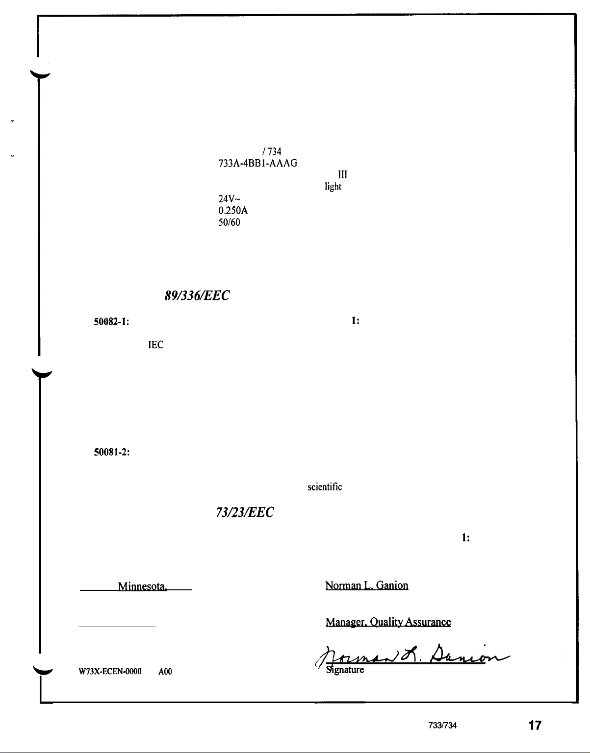
Declaration of Conformity
Declares that the following product:
WATLOW CONTROLS
124 1 Bundy Boulevard
Winona, Minnesota 55987
USA
Designation:
Model Number:
Classification:
Rated Voltage:
Rated Current:
Rated Frequency:
Maximum Power Input:
Meets the essential requirements of the following European Union Directive(s) using the
relevant section(s) of the normalized standards and related documents shown:
89/336ZEEC
EN
50082-1:
EN 50082-2:
1992
IEC
IEC 801-5:
1995
EN 6 1000-4-2:
EN 6 1000-4-4:
ENV 50141:
EMC Generic immunity standard, Part I: Residential, commercial, and light industry
801-3:
EMC Generic immunity standard, Part 2: Industrial environment
Series 733
733A-4BB l-AAAG
Electronic Incorporated Class
Type 2C action, for use in
24V-
0.25OA
50/60
15 Watts
Electromagnetic Compatibility Directive
1984
1991
1995
1995
1993
I734
(VAC)
Hz
Radiated immunity
Surge immunity
Electrostatic discharge
Electrical fast transients
Conducted immunity
III
temperature controller,
light
industrial environment
EN
50081-2:
EN 60730-1:
Winona.
Place of Issue
October 26. 1995
Date of Issue
W73X-ECEN-0000
Appendix
Minnd.
1994
EN 55011:
1993
USA
Rev
A00
EMC Generic emission standard, Part 2: Industrial environment
1991
73/23/EEC
Automatic electrical controls for household and similar use, Part 1: General requirements
Limits and methods of measurement of radio disturbance characteristics
of industrial,
scientitic
and medical radio-frequency equipment (Class B)
Low- Voltage Directive
NkI
Name of Authorized Representative
ASS_
Title of Authorized Representative
of Authorized Representative
WATLOW Series 733/734 Program Manual
17
Page 37

Notes
Appendix
WATLOW Series 733/734 Service Manual
37
Page 38

Notes
38
WATLOW Series 733/734 Service Manual
Appendix
Page 39

Appendix
WATLOW Series 733/734 Service Manual
39
Page 40

Watlow Series 733/734 Service Manual
Watlow Controls, 1241 Bundy Blvd., P.O. Box 5580, Winona, MN 55987-5580, 507/454-5300, Fax: 507/452-4507
40
WATLOW Series 733/734 Service Manual
Appendix
 Loading...