

Page 1
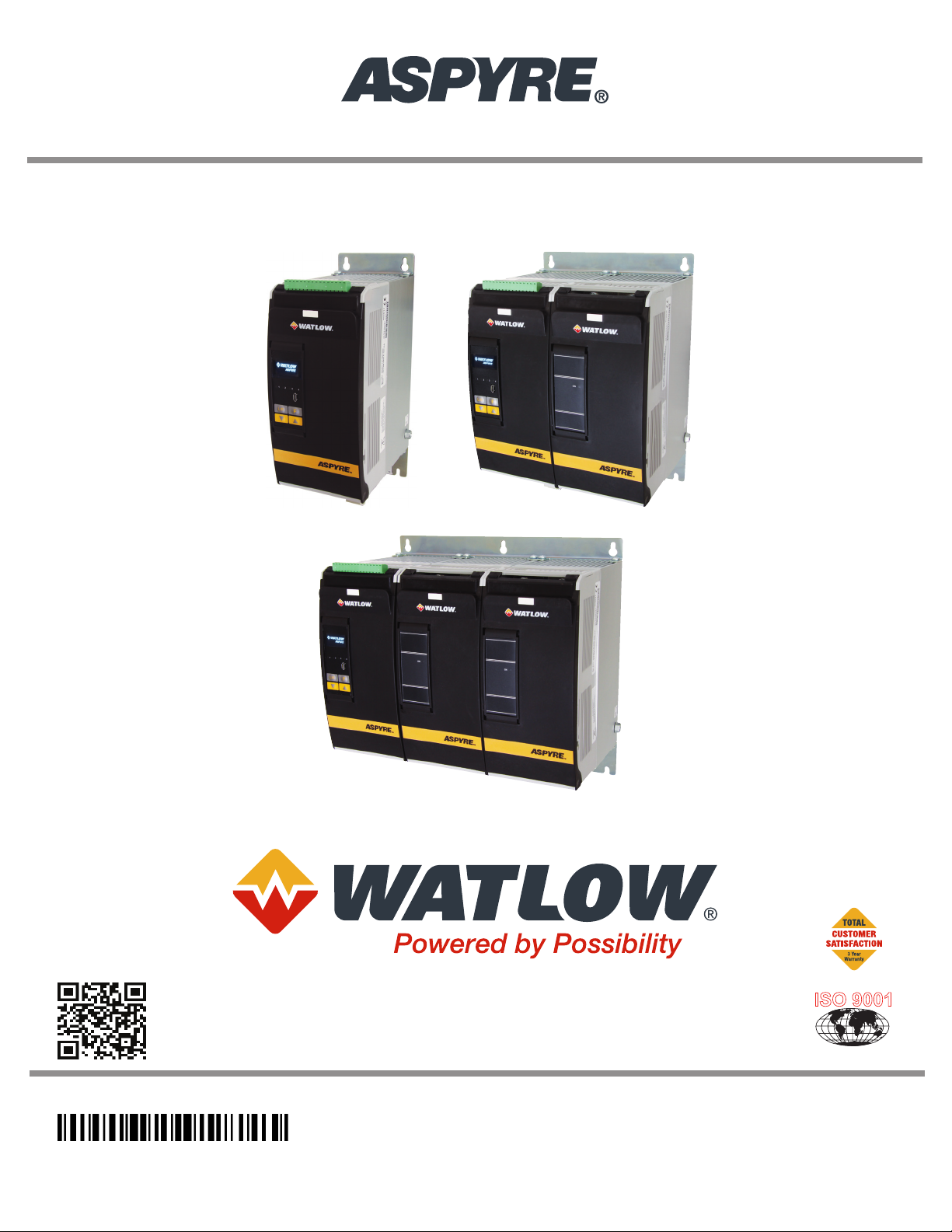
60A to 210A Power Controller
ISO 9001
User’s Guide
1917-1409 Rev D
March 2019
1241 Bundy Boulevard., Winona, Minnesota USA 55987
Phone: +1 (507) 454-5300, Fax: +1 (507) 452-4507
http://www.watlow.com
Registered Company
Winona, Minnesota USA
Page 2
Safety Information
We use note, caution and warning symbols throughout this book to draw your attention to important operational
and safety information.
A “NOTE” marks a short message to alert you to an important detail.
A “CAUTION” safety alert appears with information that is important for protecting your equipment and performance. Be especially careful to read and follow all cautions that apply to your application.
A “WARNING” safety alert appears with information that is important for protecting you, others and equipment
from damage. Pay very close attention to all warnings that apply to your application.
The safety alert symbol, (an exclamation point in a triangle) precedes a general CAUTION or WARNING
statement.
The electrical hazard symbol, (a lightning bolt in a triangle) precedes an electric shock hazard CAUTION or
WARNING safety statement. Further explanations follow:
Symbol Explanation
CAUTION – Warning or Hazard that needs further explanation than the label on unit can provide.
Consult User's Guide for further information.
Electrical Shock Hazard - Symbol (a lightning bolt in a triangle) precedes an electric shock hazard
CAUTION or WARNING safety statement.
ESD Sensitive product, use proper grounding and handling techniques when installing or servicing
product.
Do not throw in trash, use proper recycling techniques or consult manufacturer for proper disposal.
Unit is a Listed device per Underwriters Laboratories. It has been investigated to ANSI/UL® 508
standards for Industrial Control Switches and equivalent to CSA C22.2 #14. For more detail search
for File E73741 on www.ul.com.
Unit is compliant with European Union directives. See Declaration of Conformity for further details on Directives and Standards used for Compliance.
WARNING! To avoid damage to property and equipment, injury and loss of life, adhere to applicable electrical codes and standard wiring practices when installing and operating this product. Failure to do so could result
in damage, injury and death.
AVERTISSEMENT! Pour éviter d’endommager la propriété et l’équipement, les blessures et la perte de vie,
respecter les codes électriques en vigueur et les pratiques de câblage standard au moment de l’installation et
de l’utilisation de ce produit. Dans le cas contraire, cela peut entraîner la mort, des blessures graves ou des
dommages.
WARNING! All service including inspection, installation, wiring, maintenance, troubleshooting, fuse or other
user-serviceable component replacement must be performed only by properly qualied personnel. Service personnel must read this manual before proceeding with work. While service is being performed other, unqualied
personnel should not work on the unit or be allowed in the immediate vicinity.
AVERTISSEMENT! Tous les services, y compris l’inspection, l’installation, le câblage, l’entretien, le dépannage, le remplacement de fusibles ou d’autres composants pouvant être réparés par l’utilisateur, doivent être
Watlow - ASPYRE 60A to 210A Power Controller • 2 •
Page 3

effectués uniquement par un personnel dûment qualié. Le personnel de service doit lire ce manuel avant d’effectuer tout travail. Pendant que l’entretien est exécuté, tout personnel non qualié ne doit effectuer de travail
sur l’appareil ni se trouver à proximité.
WARNING! When in use the power controller is connected to dangerous voltages. Do not remove the protec-
tive covers without rst disconnecting and preventing power from being restored while servicing the unit.
AVERTISSEMENT! Au moment de l’utilisation, le régulateur de puissance est connecté à des tensions dangereuses. Ne retirer aucun couvercle de protection sans d’abord débrancher l’appareil et ainsi empêcher l’alimentation d’être rétablie pendant l’entretien.
WARNING! Do not use in aerospace or nuclear applications.
AVERTISSEMENT! Ne pas utiliser pour les applications aérospatiales ou nucléaires.
WARNING! The power controller’s protection rating is IP20 with all covers installed and closed. It must be
installed in an enclosure that provides all the necessary additional protections appropriate for the environment
and application.
AVERTISSEMENT! L’indice de protection du régulateur de puissance est de IP20 lorsque les couvercles sont
installés et fermés. L’appareil doit être installé dans une enceinte qui assure toute la protection supplémentaire
nécessaire pour l’environnement et l’application.
WARNING! Ground the power controller via the provided protective earth grounding terminal. Verify ground
is within impedance specications. This should be veried periodically.
AVERTISSEMENT! Mise à la terre du régulateur de puissance par le biais de la borne de prise de terre de
protection fournie. Vérier que la prise de terre est conforme aux spécications de l’impédance. Cela doit être
vérié périodiquement.
WARNING! Electric Shock Hazard: when the power controller has been energized, after shutting off the power, wait at least one minute for internal capacitors to discharge before commencing work that brings you in to
contact with power connections or internal components.
AVERTISSEMENT! Risque de décharges électriques : lorsque le régulateur de puissance est mis sous tension,
après avoir été éteint, attendre au moins une minute pour que les condensateurs internes se déchargent avant
de commencer tout travail incluant le contact avec les connexions électriques ou les composants internes.
WARNING! The installation must be protected by electromagnetic circuit breakers or by fuses. The semicon-
ductor fuses located inside the power controller are classied for UL® as supplementary protection for semicon-
ductor devices. They are not approved for branch circuit protection.
AVERTISSEMENT! L’installation doit être protégée par des disjoncteurs électromagnétiques ou des fusibles.
Les fusibles pour semi-conducteurs situés à l’intérieur du régulateur de puissance sont classés UL® comme protection supplémentaire pour les dispositifs pour semi-conducteurs. Ils ne sont pas approuvés pour la protection
des circuits de dérivation.
WARNING! When making live voltage or current measurements, use proper personal protective equipment
for the voltages and arc-ash potentials involved.
Watlow - ASPYRE 60A to 210A Power Controller • 3 •
Page 4

AVERTISSEMENT! Au moment de relever des mesures de tension ou de courant en direct, utiliser un équipe-
ment de protection individuelle approprié pour les tensions et les potentiels d’arc électrique concernés.
WARNING! Verify the voltage and current ratings of the power controller are correct for the application.
AVERTISSEMENT! Vérier que les valeurs de tension et de courant du régulateur de puissance sont correctes
pour l’application.
CAUTION: To avoid compromising the insulation, do not bend wire or other components beyond their bend
radius specications.
ATTENTION : Pour éviter de compromettre l’isolation, ne pas plier le l ou tout autre composant au-delà de
ses spécications en matière de rayon de courbure.
CAUTION: Protect the power controller from high temperature, humidity and vibrations.
ATTENTION : Protéger le régulateur de puissance contre les températures élevées, l’humidité et les vibra-
tions.
CAUTION: The power controller warranty is void if the tested and approved fuses are not used.
ATTENTION : La garantie du régulateur de puissance est nulle si aucun fusible testé et approuvé n’est util-
isé.
CAUTION: Only trained and authorized personnel should access and handle the internal electronics and they
must follow proper electro-static prevention procedures.
ATTENTION : Seul le personnel formé et autorisé peut accéder aux composants électroniques internes et les
gérer, et il doit se conformer à des procédures de prévention électrostatique appropriées.
CAUTION: Install an appropriately sized RC lter across contactor coils, relays and other inductive loads.
ATTENTION : Installer un ltre RC de dimensions appropriées sur les bobines du contacteur, les relais et
autres charges par induction.
NOTE! Provide a local disconnect to isolate the power controller for servicing.
REMARQUE : Fournir une déconnexion locale an d’isoler le régulateur de puissance pour l’entretien.
NOTE! The nominal current is specied for ambient temperatures at or below 40° C. Ensure the application
design allows for adequate cooling of each power controller. The power controller must be mounted vertically.
The cooling design must prevent air heated by one power controller from causing power controllers mounted
above to exceed the ambient operating temperature limit. When power controllers are mounted side by side
allow a minimum spacing of 15mm between them.
Watlow - ASPYRE 60A to 210A Power Controller • 4 •
Page 5

REMARQUE : Le courant nominal est précisé pour des températures ambiantes égales ou inférieures à 40°C.
S’assurer que la conception de l’application permette le refroidissement adéquat de chaque régulateur de
puissance. Le régulateur de puissance doit être monté verticalement. La conception de refroidissement doit
empêcher l’air chauffé par le régulateur de puissance de dépasser la limite de température de fonctionnement
ambiante de la part des régulateurs de puissance montés au-dessus. Lorsque les régulateurs de puissance sont
montés côte à côte, il faut conserver un espacement minimal de 15 mm entre les deux.
NOTE! Use only copper cables and wires rated for use at 75°C or greater.
REMARQUE : N’utiliser que des câbles et des ls en cuivre pour l’utilisation à 75°C ou plus.
Technical Assistance
If you encounter a problem with your Watlow® controller, review your conguration information to verify that
your selections are consistent with your application: inputs, outputs, alarms, limits, etc. If the problem persists,
you can get technical assistance from your local Watlow representative (see back cover), by e-mailing your questions to wintechsupport@watlow.com or by dialing +1 (507) 494-5656 between 7 a.m. and 5 p.m. Central Time
USA & Canada. Ask for for an Applications Engineer. Please have the complete model number available when
calling.
Return Material Authorization (RMA)
1. Call Watlow Customer Service, (507) 454-5300, for a Return Material Authorization (RMA) number before
returning any failed product to Watlow. If you do not know why the product failed, contact an Application
Engineer. All RMA’s require:
• Ship-to address
• Bill-to address
• Contact name
• Phone number
• Method of return shipment
• Your P.O. number
• Detailed description of the problem
• Any special instructions
• Name and phone number of person returning the product
2. Prior approval and an RMA number from the customer service department is required when returning any
product. Make sure the RMA number is on the outside of the carton and on all paperwork returned. Ship on
a freight prepaid basis.
3. After we receive your return, we will examine it to verify the reason for the product failure. Unless otherwise agreed to in writing, Watlow’s standard warranty provisions, which can be located at, www.watlow.
com/terms, will apply to any failed product.
4. In the event that the product is not subject to an applicable warranty, we will quote repair costs to you
and request a purchase order from you prior to proceeding with the repair work.
5. Watlow reserves the right to charge for no trouble found (NTF) returns.
Warranty
The ASPYRE® power controller is warranted by Watlow for a period of 36 months in accordance with the terms
and conditions set forth on Watlow’s website, which may be accessed at www.watlow.com/terms.
Watlow - ASPYRE 60A to 210A Power Controller • 5 •
Page 6

Document Number: 10-03359 Rev. D
©2019 Watlow Electric Manufacturing Company, all rights reserved.
Watlow® and ASPYRE® are registered trademarks of Watlow Electric and Manufacturing Company.
Cooper Bussman® is a registered trademark of Cooper Industries Inc.
EtherNet/IP™ is a trademark of Open DeviceNet Vendors Association.
Kanthal® is a registered trademark of Bulten-Kanthal Aktiebolag Joint Stock Company
Windows® is a registered trademark of Microsoft Corporation.
Modbus® is a registered trademark of Schneider Automation Incorporated.
Siemens® is a registered trademark of Siemens Aktiengesellschaft Corporation.
UL® is a registered trademarks of Underwriter’s Laboratories, Inc.
Watlow - ASPYRE 60A to 210A Power Controller • 6 •
Page 7

TC
Contents
Safety Information ......................................................2
Technical Assistance ....................................................5
Return Material Authorization (RMA) .......................................5
Warranty ..............................................................5
Overview ...........................................11
Recognizing Product Features ............................................11
Identifying the Product ..................................................11
Product Selection ......................................................12
Features and Benefits ...................................................14
Product Block Diagram .................................................15
Installation ..........................................17
Installing the ASPYRE Power Controller ....................................17
Environmental Conditions ...............................................17
Cooling Requirements ..................................................18
Mounting Dimensions 480V and 600V ......................................19
Mounting Dimensions 690V ..............................................20
Wiring 480V and 600V Units ..............................21
Wiring the ASPYRE Power Controller ......................................21
Good Wiring Practices ..................................................21
Wiring Overview 480V and 600V Units .....................................22
Wire Selection, Prep and Torque ..........................................23
Terminal Strip Connections ..............................................24
Connecting Control Signals ..............................................25
Powering the Cooling Fans. . . . . . . . . . . . . . . . . . . . . . . . . . . . . . . . . . . . . . . . . . . . . . . 28
Connecting the Auxiliary Power (DT1 and DT2 Only). . . . . . . . . . . . . . . . . . . . . . . . . . . 28
Opening The Covers ....................................................29
Wiring the Line Power and Load ..........................................29
Wiring 690V Units .....................................31
Wiring the ASPYRE Power Controller ......................................31
Good Wiring Practices ..................................................31
Wiring Overview 690V Units .............................................32
Wire Selection, Prep and Torque ..........................................34
Removing the Covers ...................................................35
Connecting Control Signals ..............................................35
Powering the Cooling Fans. . . . . . . . . . . . . . . . . . . . . . . . . . . . . . . . . . . . . . . . . . . . . . . 39
Connecting the Auxiliary Power ...........................................40
Wiring the Line Power and Load ..........................................40
Initial Setup .........................................43
Using the ASPYRE Configurator Software ...................................43
Configuring the ASPYRE Power Controller ..................................43
Watlow - ASPYRE 60A to 210A Power Controller • 7 •
Page 8

Operation ...........................................47
Control Panel .........................................................47
Menu Navigation ......................................................48
Indicators (LEDs) ......................................................49
Alarms and Messages ..................................................50
Using ASPYRE Configurator ..............................51
Overview ............................................................51
How To ..............................................................51
Reference ............................................................56
Parameter Reference ...................................65
Alarm Function ........................................................65
Analog In 1 [Signal Type] ................................................65
Analog In 1 [Value] ....................................................66
Analog In 2 [Signal Type] ................................................66
Analog In 2 [Value] ....................................................66
Analog In 2 Function ...................................................66
Aux Voltage ..........................................................66
Bakeout Current (Models with Current Limit) ................................66
Bakeout Off Time (Models with Current Limit) ................................67
Bakeout Ramp Time (Models with Current Limit) .............................67
Command Bits ........................................................67
Cycle Time ...........................................................68
Delay ...............................................................68
Digital In 1 ...........................................................68
Digital In 1 Function ....................................................68
Digital In 2 ...........................................................69
Digital In 2 Function ....................................................69
Enable. . . . . . . . . . . . . . . . . . . . . . . . . . . . . . . . . . . . . . . . . . . . . . . . . . . . . . . . . . . . . . . 69
Ethernet Address ......................................................69
Ethernet Subnet .......................................................70
Ethernet Gateway ......................................................70
Feedback ............................................................70
Firing ...............................................................70
Frequency ...........................................................71
Half Cycles to Delay ....................................................71
Heater Bakeout (Models with Current Limit) .................................71
HH:MM:SS ...........................................................71
Host Name ...........................................................71
Htr Break Delay .......................................................71
Htr Break Sensitivity ....................................................71
I Limit (Models with Current Limit) ........................................72
I Limit Local / Remote (Models with Current Limit) ............................72
I Output .............................................................72
Integral Current (Models with Current Limit) ................................72
Integral Power ........................................................72
kVA Real Time ........................................................72
kW Real Time .........................................................72
Watlow - ASPYRE 60A to 210A Power Controller • 8 •
Page 9

kW Total .............................................................73
Leg 1 I Output (DT2 and DT3 Models) ......................................73
Leg 2 I Output (DT2 and DT3 Models) ......................................73
Leg 3 I Output (DT2 and DT3 Models) ......................................73
Limit Peak Current (Models with Current Limit) ..............................73
Load Ω ..............................................................73
Logging .............................................................73
Logging Interval .......................................................74
Max Current .........................................................74
Max Voltage ..........................................................74
Min Cycles ...........................................................74
MM/DD/YY ...........................................................74
Neutral Connected (DT2 and DT3 Models) ...................................74
Nominal I ............................................................74
Nominal V. . . . . . . . . . . . . . . . . . . . . . . . . . . . . . . . . . . . . . . . . . . . . . . . . . . . . . . . . . . . 75
Out Scale ............................................................75
Port 1 Address ........................................................75
Port 1 Baud ..........................................................75
Port 2 ...............................................................75
Port 2 Access .........................................................76
Port 2 Address ........................................................76
Port 2 Baud ..........................................................76
Power ..............................................................76
Power Factor .........................................................76
Prop Band Current (Models with Current Limit) ..............................76
Prop Band Power ......................................................77
Release ..............................................................77
Remote SP ...........................................................77
Retransmit (Models with Retransmit) ......................................77
Retransmit Scale (Models with Retransmit) ..................................78
Retransmit Type (Models with Retransmit) ..................................78
Safety Ramp Duration ..................................................78
Safety Ramp Off Time ..................................................78
SCR Temperature ......................................................79
Serial Number ........................................................79
Set Point ............................................................79
Set Point Source ......................................................79
Soft Start ............................................................79
Start Ramp ...........................................................79
Startup Display ........................................................80
Status Bits ...........................................................80
Thermal Alarm Counter .................................................80
Unit Type ............................................................80
User Access Level .....................................................81
V Input .............................................................81
V Output .............................................................81
Version ..............................................................81
Watchdog ............................................................81
Watlow - ASPYRE 60A to 210A Power Controller • 9 •
Page 10

Watchdog Reset Time ..................................................81
Wi-Fi ................................................................82
Wi-Fi Address .........................................................82
Features ...........................................83
Closed Loop Control. . . . . . . . . . . . . . . . . . . . . . . . . . . . . . . . . . . . . . . . . . . . . . . . . . . . 83
Feedback ............................................................84
Current Limit .........................................................86
Configurable Inputs and Outputs ..........................................86
Firing Types ..........................................................88
Soft Start ............................................................94
Start Ramp (DT1 and DT3 Models) ........................................94
Safety Ramp (DT1 and DT3 Models) .......................................95
Heater Bakeout Function (Models with Current Limit) ..........................95
Totalizer .............................................................95
Data Logging .........................................................96
Maintenance & Troubleshooting ...........................97
Routine Maintenance ...................................................97
Alarms and Indicators ..................................................97
Opening The Covers ....................................................99
Replacement Fuses ...................................................100
Replacing the Battery ..................................................100
Calibration Procedures .................................................101
Updating the Firmware .................................................103
Troubleshooting ......................................................104
Troubleshooting Schematics ............................................105
Communication ......................................111
Overview ...........................................................111
Enabling the Secondary Port ............................................112
Ethernet Network Setup ................................................112
Modbus® TCP ........................................................113
EtherNet/IP™ Setup ...................................................113
Profinet IO Setup .....................................................116
Profibus DP Setup ....................................................121
Holding Registers .....................................................127
Input Registers .......................................................128
Modbus® RTU .......................................................130
Modbus® RTU Holding Registers .........................................131
Specifications .......................................135
Declaration of Conformity ..............................................141
Watlow - ASPYRE 60A to 210A Power Controller • 10 •
Page 11
1
Overview
This chapter describes how to locate the model number of the ASPYRE® power controller, explains how to deter-
mine which ordering options are present, identies its physical features, lists its main functional features and
benets and provides a functional overview in the form of a block diagram.
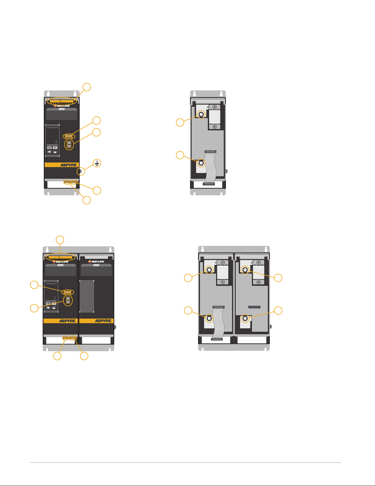
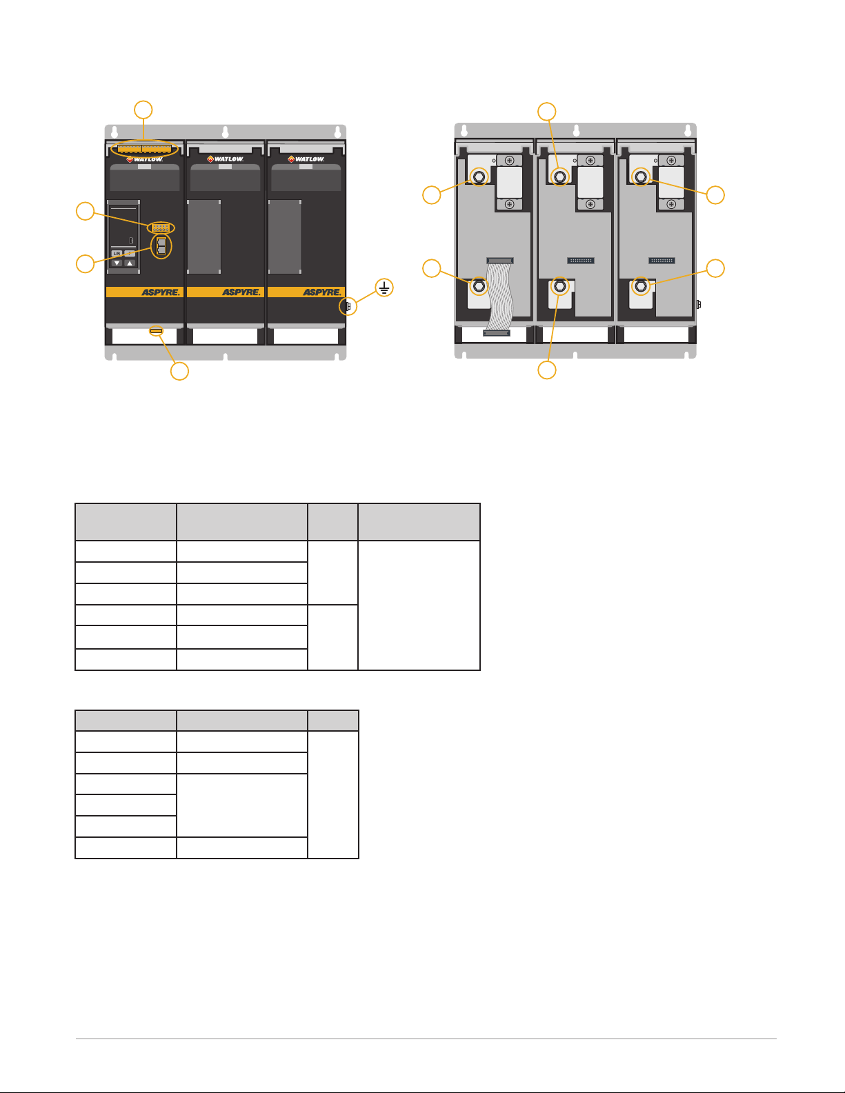
Recognizing Product Features
This illustration indicates the physical features of the product as referenced in this manual.
Line power connection
Mounting slots (top and bottom)
Product identification label
Part number label Part number label
Control panel
Load power connection
Cover handle
USB connector
Earth ground connection
Identifying the Product
To identify the power controller, locate the part number on the product identication label, see the illustration.
With the part number and the part number table you can determine important characteristics of the power controller.
Product Identification Label
The product identication label includes not only the part number but also the voltage and current ratings and
auxiliary and fan voltage requirements.
Sample Label
Max. Load Current
Max. Load Voltage
Auxiliary Voltage
Fan Voltage
Second Port
Watlow - ASPYRE 60A to 210A Power Controller • 11 • Chapter 1 Overview
: 120A
: 600Vac ~ 50/60Hz
: 540-660Vac ~ 50/60Hz 6VA
: 120 VAC
: Modbus TCP
1 Phase 1 Leg Control
Use Wire rated 75°C,
Max Ambient 40°C
For use in Pollution
Degree 2 Environment
User Manual:
1917-1409
Page 12
Part Number
NOTE! No UL® on 690V models.
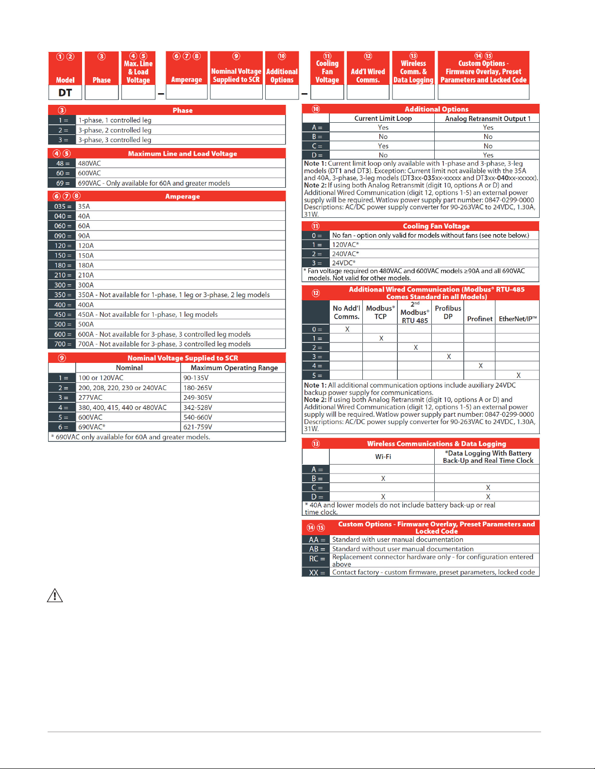
Product Selection
This section describes how to choose the appropriate ordering options.
Digit 3, Phase
Choose the number of switched legs. Ungrounded-wye and delta loads are most economically controlled with
two-leg switching. Grounded-wye and open-delta loads require three-leg switching.
Watlow - ASPYRE 60A to 210A Power Controller • 12 • Chapter 1 Overview
Page 13
Digits 4 and 5, Maximum Line and Load Voltage
V
V
V
V
V
V
V
Choose the lowest voltage range that is equal to or greater than the nominal voltage supplied to the ASPYRE
power controller. The actual voltage is specied with digit 9.
Digits 6, 7 and 8, Amperage
These digits indicate the maximum current that can be switched. Choose a power controller with adequate current capacity for your load. Use one of the formulas below to determine the nominal load current based on the
load conguration, the line voltage and the load power or resistance.
In the formulas below:
• I is the nominal load current calculated according to the formula
• P is the total power of the load
• R is the resistance of each heating element
• V is the nominal voltage supplied to the ASPYRE power controller (see the 9
th
digit in the part number)
Single Phase Resistive Load
I
P
V
1.73V
=
I
V
=
R
P
1.73V
1.73V
=
R
P
=
V
1.73R
=
I
R
2-Leg, 3-Phase Resistive Load in Delta Conguration
I
=
R
R
3-Leg, 3-Phase Resistive Load in Grounded Wye Cong.
R R R
I
R
I
2-Leg, 3-Phase Resistive Load in Wye Conguration
I
P
=
I
R R R
3-Leg, 3-Phase Resistive Load in Wye Conguration
R R R
3-Leg, 3-Phase Resistive Load in Delta Conguration
R
R
1.73V
I
I
I
=
I
=
1.73V
P
1.73V
P
=
=
=
V
1.73R
V
1.73R
1.73V
R
R
3-Leg, 3-Phase Resistive Load in Open Delta Conguration
I
R
R
R
Watlow - ASPYRE 60A to 210A Power Controller • 13 • Chapter 1 Overview
P
=
I
3V
V
=
R
Page 14

Digit 9, Nominal Voltage Supplied to SCR
Choose the voltage the will be used to power the load. This is also the voltage for the auxiliary power supply
input. The voltage chosen here must be less than or equal to the Maximum Line and Load Voltage chosen with
digits 4 and 5.
Digit 10, Current Limit Loop and Analog Retransmit Output 1*
Choose if the power controller limits current and/or can retransmit load voltage, current, power or measured
input. The current limit option is available only with single phase and three-phase, three-leg models.
Digit 11, Cooling Fan Voltage
For power controllers that switch 90A or more, choose the voltage you will supply to power the fans in the ASPYRE power controller. Models that switch less than 90A do not require or include cooling fans.
Digit 12, Additional Wired Communication Option*
If desired, choose an optional communication port in addition to the EIA-485, Modbus® RTU port that comes standard on all models.
Digit 13, Wireless Communication and Data Logging Option
Choose the desired combination of Wi-Fi and data logging options.
Characters 14 and 15, Custom Options
Choose the desired options or use a factory supplied two-character option.
*If using both analog retransmit (digit 10, options A or D) and additional wired communication (digit 12, options 1
to 5) an external power supply is required.
Features and Benefits
This section provides a high-level overview of the features and benets of the ASPYRE power controller.
Heater bakeout
• Protects heater upon start up
• Eliminates labor and time associated with checking for wet heaters
Integrated semiconductor fusing, current transformer and user interface
• Saves installation time and eases setup and commissioning
• Delivers a user-friendly, intuitive interface
Industry-leading design and serviceability
• Offers a robust SCR design to meet a rugged industrial environment’s high quality and reliability needs
• Provides quick and easy access to maintain and service fuses and individual legs in minimal time
• Enables fast troubleshooting by providing helpful thermal system diagnostics
Comprehensive power controller range
• Provides wide range of options from simple single phase to complex three-phase loads to 690V
100KA short circuit current rating (SCCR)
• Enables greater protection in the event of a short circuit
c-UL® 508 Listed
• Shortens project schedules, agency testing and expenses
Control modes: contactor, voltage, current or power
• Satises a wide range of demanding thermal applications
Watlow - ASPYRE 60A to 210A Power Controller • 14 • Chapter 1 Overview
Page 15
Load firing modes: zero-cross, burst fire, phase angle, soft start, half-cycle, single-cycle, delayed trig-
Voltage
Sensing
Analog
Input
USB Device
• Configuration
Software Connection
• Data Log File Transfer
Analog
Retransmit
• User-Selectable
Retransmit Parameter
DC Power
Supply
• Dry Contact
Switches
• Potentiometers
WiFi
• Configuration
• Monitor Operation
2 Analog Inputs
• Set Point
• Feedback
• Current Limit*
2 Digital Inputs
• Enable
• Select Feedback
• Local/Remote
• Set Firing Type
Auxiliary Power
• Controller
Electronics
• Voltage Sensing
• Zero-Cross Sensing
Mechanical
Relay Output
• Alarm Annunciation
Fan Power
• 120VAC
• 240VAC
• 24VDC
Out to LoadIndustrial Communications
• Modbus
®
TCP
• EtherNet/IP™
• 2nd Modbus
®
RTU (485)
Analog
Input
Data
Logging
RS-485
Interface
NCNO
Analog
Retransmit
Current
Sensing
Power
Demand
Loop
(Optional)
(Optional)
(Optional)
•
Profibus DP
• Profinet
(Optional)
(Optional)
+10 VDC
Output
Current
Limit
Loop*
Fan Power
Input
Auxiliary
Power
Supplemental
Power
• Retransmit
• Communications
+24 VDC
Input
* Single-phase and three-phase, three-leg models only
Power Switching
• 1, 2 or 3 Legs
• Back-to-Back SCR Switching
• Replaceable Semiconductor Fuses
(Optional)
(Optional)
(Optional)
gering
• Handles a wide range of load types including nichrome, medium and long waveform infrared lamps, moly,
transformers, silicon carbide, UV lamps and tungsten
• Protects and extends the life of connected loads
Wide range of communication protocols
• Enable factory and process automation with connectivity to process and equipment data via Modbus® RTU,
Modbus® TCP, EtherNet/IP™ , Wi-Fi, Probus, Pronet, USB device (conguration and data le transfers)
Open heater and shorted SCR indication
• Minimizes production downtime with easy to understand, intelligent, troubleshooting diagnostics
Integrated USB and user interface for configuration
• Easily and safely program conguration settings as the user interface can be powered through USB connection
• Eliminates need to work in a high voltage hazard environment. High voltage to the power controller and
system panel can be shut off and locked out for safety while conguring controller.
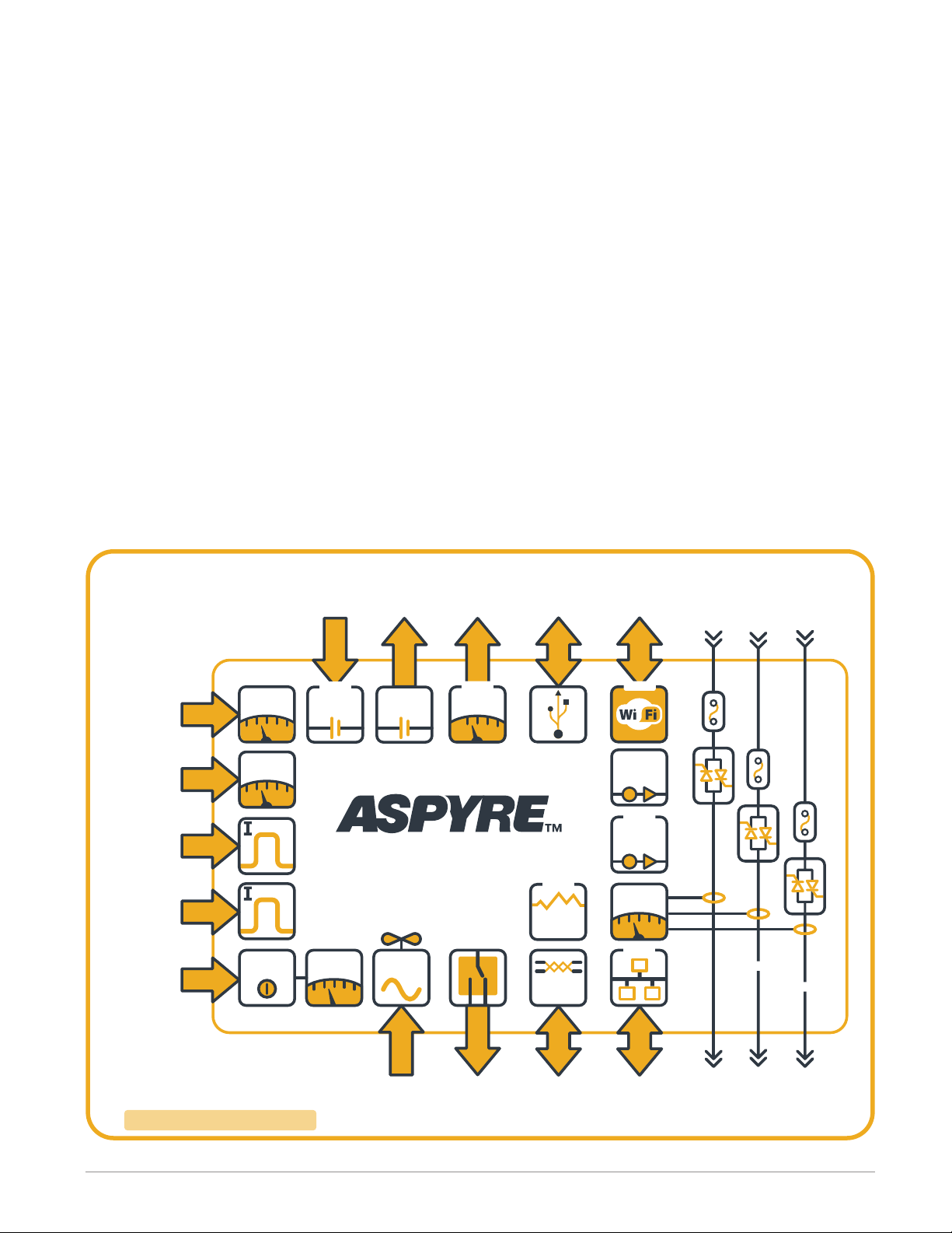
Product Block Diagram
This diagram represents the features and functions of the ASPYRE power controller in a graphical format showing
the relationships between various functions. Optional features are indicated.
Product Block Diagram for 60A to 210A Models
Watlow - ASPYRE 60A to 210A Power Controller • 15 • Chapter 1 Overview
Page 16

Wi-Fi Transmitter Module
Models DT_ _ _-_ _ _ _-_ _ _[B or D]_ _ contain a Wi-Fi transmitter module. See the label on the module to
determine which of the following modules is installed. The transmitter module is mounted on the top of the
microprocessor board visible when the center cover is tipped forward.
Module FCC ID: 2ADUIESP-12-F WiFi module 802.11b/g/n 2412-2462 MHz
Output power:
• 802.11b: 15.58 dBm (Max.)
• 802.11g: 13.72 dBm (Max.)
• 802.11n: 12.53 dBm (Max.)
Antenna gain: 1.0 dBi PCB antenna 11 channels.
Module FCC ID: 2AL3B-ESP-F 802.11b/g/n 2412-2462 MHz
Output power:
• 802.11b: 14.0 dBm (Max.)
• 802.11g: 12.8 dBm (Max.)
• 802.11n: 13.6 dBm (Max.)
Antenna gain: 1.0 dBi PCB antenna 11 channels.
Unit is assembled from tested components, complete system not tested.
This equipment has been tested and found to comply with the limits for a Class B digital device, pursuant to Part
15 of the FCC Rules. These limits are designed to provide reasonable protection against harmful interference in
a residential installation. This equipment generates, uses and can radiate radio frequency energy and, if not installed and used in accordance with the instructions, may cause harmful interference to radio communications.
However, there is no guarantee that interference will not occur in a particular installation.
If this equipment does cause harmful interference to radio or television reception, which can be determined by
turning the equipment off and on, the user is encouraged to try to correct the interference by one or more of
the following measures:
• Reorient or relocate the receiving antenna.
• Increase the separation between the equipment and receiver.
• Connect the equipment into an outlet on a circuit different from that to which the receiver is connected.
• Consult the dealer or an experienced radio/TV technician for help.
Watlow - ASPYRE 60A to 210A Power Controller • 16 • Chapter 1 Overview
Page 17

2
Installation
WARNING: To avoid damage to property and equipment, injury and loss of life, adhere to applicable electrical codes and standard wiring practices when installing and operating this product. Failure to do so could result
in damage, injury and death.
AVERTISSEMENT! Pour éviter d’endommager la propriété et l’équipement, les blessures et la perte de vie,
respecter les codes électriques en vigueur et les pratiques de câblage standard au moment de l’installation et
de l’utilisation de ce produit. Dans le cas contraire, cela peut entraîner la mort, des blessures graves ou des
dommages.
Installing the ASPYRE Power Controller
This chapter provides the information necessary to select and prepare a location and to mount one or more
ASPYRE power controllers.
Consider the spacing required for power, load, and control signal wiring before mounting the power controller.
Take in to account the controller dimensions, wire bending radius, and cooling requirements. Use good wiring
practices to minimize electrical noise problems.
Peripheral Components
Allow room for fuses and fuse holders for the auxiliary input power and fans (if present).
Mounting Orientation
Mount power controllers vertically.
Bend Radius
Allow adequate space to route cables without requiring bending more than permitted for the type of cable.
Environmental Conditions
Mount ASPYRE power controllers in a suitable electrical enclosure. Allow adequate wire bending space and cool-
ing. The maximum ambient temperature in the enclosure must not exceed 104°F (40°C).
Ambient Temperature
Storage Temperature
Installation Location
Altitude
Humidity
Pollution degree
32° to 104°F (0° to 40°C)
-13° to 158°F (-25°to 70°C)
Install away from direct sun light, conductive dust, corrosive gas, vibration,
water and corrosive salts.
Up to 6560 feet (2000m) above sea level
At altitudes above 3280 feet (1000m) reduce the nominal current by 2% for
each 328 feet (100m).
From 5 to 95% relative humidity, non-condensing and without ice
Installation Category III, Pollution degree 2
Watlow - ASPYRE 60A to 210A Power Controller • 17 • Chapter 2 Installation
Page 18
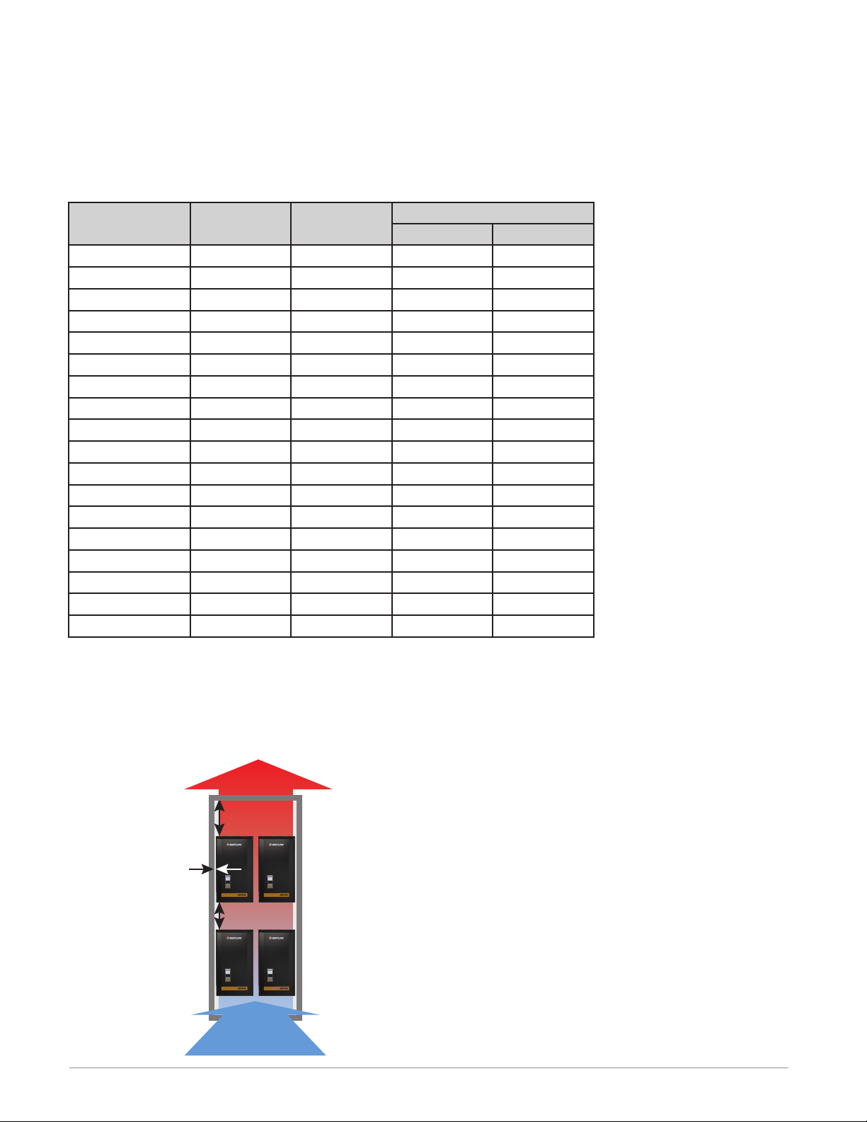
Cooling Requirements
To maintain the ambient temperature in the enclosure in which the power controller, circuit breakers, fuses and
other components are installed, there must be adequate cooling to remove the heat generated by all the devices. The power controllers are designed to be cooled by drawing cool air in from the bottom and expelling heated
air at the top. Typically cabinets are designed with one or more fans on the front door or on the top of the enclosure. The designer will need to know the heat generated by the power controller. See the table below.
Total Heat Generated by ASPYRE Power Controller
Model Current (A) Switched Legs
DT1_ _-060... 60 1 102 136
DT1_ _-090... 90 1 145 175
DT1_ _-120... 120 1 200 213
DT1_ _-150... 150 1 205 216
DT1_ _-180... 180 1 235 254
DT1_ _-210... 210 1 304 295
DT2_ _-060... 60 2 205 277
DT2_ _-090... 90 2 290 354
DT2_ _-120... 120 2 398 448
DT2_ _-150... 150 2 409 416
DT2_ _-180... 180 2 486 545
DT2_ _-210... 210 2 598 638
DT3_ _-060... 60 3 290 354
DT3_ _-090... 90 3 580 469
DT3_ _-120... 120 3 598 601
DT3_ _-150... 150 3 594 611
DT3_ _-180... 180 3 740 725
DT3_ _-210... 210 3 898 848
Generated Heat (W)
480V & 600V 690V
Spacing for Multiple Power Controllers
Maintain the minimum distances as shown in the diagram. When multiple power controllers are mounted side-byside they may be placed as close together as is practical for installation and service.
Power Controller Spacing
Hot Air
30 cm (11.8 in.)
2 cm (0.8 in.)
20 cm (7.9 in.)
Watlow - ASPYRE 60A to 210A Power Controller • 18 • Chapter 2 Installation
Outlet
Cool Air
Intake
Page 19
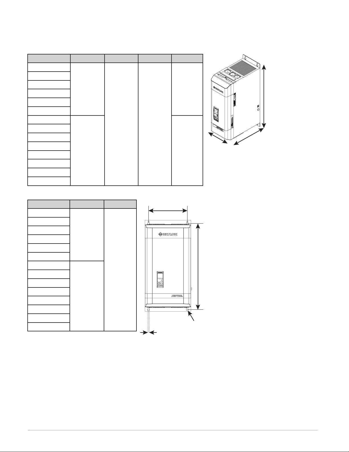
Mounting Dimensions 480V and 600V
See the tables for the product dimensions, weight and keyhole mounting slot locations and size.
Note! 60A units do not have Fans; 90A to 210A units have fans.
Power Controller Dimensions and Weight
Model W H (no fan) H (with fan) D
DT1...
DT2...
DT3...
3.66 in.
93 mm
7.36 in.
187 mm
11.06 in.
281 mm
10.61 in.
270 mm
10.79 in.
274 mm
6.69 in.
170 mm
Weight
(no fans)
7.5 lb.
3.4 kg
15.0 lb.
6.8 kg
22.4 lb.
10.2 kg
Weight
(with fans)
7.9 lb.
3.6 kg
15.4 lb.
7.0 kg
23.3 lb.
10.6 kg
Mounting Slot Locations
Model A B (no fans) B (with fans)
DT1...
DT2...
DT3...
Slot Locations
2.80 in.
71 mm
6.50 in.
165 mm
5.10 in.
129.5 mm
2 pl.
10.06 in.
256 mm
10.24 in.
0.35 in. (9 mm) diameter typical
A
A A A
Dimensions
W
D
260 mm
H
B
0.20 in. (5 mm) typical
Watlow - ASPYRE 60A to 210A Power Controller • 19 • Chapter 2 Installation
Page 20
Mounting Dimensions 690V
See the tables for the product dimensions, weight and keyhole mounting slot locations and size.
Power Controller Dimensions and Weight
Model W H D Weight
DT_ _ _-060...
DT_ _ _-090...
DT1 _ _-120...
DT1 _ _-150...
DT1 _ _-180...
DT1 _ _-210...
DT2_ _-120...
DT2_ _-150...
DT2_ _-180...
DT2_ _-210...
DT3_ _-120...
DT3_ _-150...
DT3_ _-180...
DT3_ _-210...
Mounting Slot Locations
Model A B
DT_ _ _-060...
DT_ _ _-090...
DT1 _ _-120...
DT1 _ _-150...
DT1 _ _-180...
DT1 _ _-210...
DT2_ _-120...
DT2_ _-150...
DT2_ _-180...
DT2_ _-210...
DT3_ _-120...
DT3_ _-150...
DT3_ _-180...
DT3_ _-210...
5.39 in.
137 mm
10.32 in.
262 mm
3.82 in.
97 mm
8.74 in.
222 mm
17.32 in.
440 mm
16.14 in.
410 mm
10.63 in.
270 mm
Slot Locations
0.28 in. (7 mm) typical
A
23.1 lb.
10.5 kg
39.6 lb.
18.0 kg
Dimensions
H
W
D
B
0.47 in. (12 mm) diameter typical
Watlow - ASPYRE 60A to 210A Power Controller • 20 • Chapter 2 Installation
Page 21

3
Wiring 480V and 600V Units
WARNING: To avoid damage to property and equipment, injury and loss of life, adhere to applicable electrical codes and standard wiring practices when installing and operating this product. Failure to do so could result
in damage, injury and death.
AVERTISSEMENT! Pour éviter d’endommager la propriété et l’équipement, les blessures et la perte de vie,
respecter les codes électriques en vigueur et les pratiques de câblage standard au moment de l’installation et
de l’utilisation de ce produit. Dans le cas contraire, cela peut entraîner la mort, des blessures graves ou des
dommages.
WARNING: The installation must be protected by electromagnetic circuit breakers or by fuses. The semicon-
ductor fuses located inside the power controller are classied for UL® as supplementary protection for semicon-
ductor devices. They are not approved for branch circuit protection.
AVERTISSEMENT! L’installation doit être protégée par des disjoncteurs électromagnétiques ou des fusibles.
Les fusibles pour semi-conducteurs situés à l’intérieur du régulateur de puissance sont classés UL® comme protection supplémentaire pour les dispositifs pour semi-conducteurs. Ils ne sont pas approuvés pour la protection
des circuits de dérivation.
Wiring the ASPYRE Power Controller
This chapter describes how to select, prepare and attach power and signal wires to the power controller.
Good Wiring Practices
Follow good wiring practices to minimize the effects of interference from nearby equipment and the line power
on the operation of the power controller:
• Install an appropriately sized RC lter across contactor coils, relays and other inductive loads
• Use shielded twisted-pair cables for input, output and communication signals
• Route control and signal cables away from motors and other sources of electromagnetic interference and
not parallel to power cables
• Follow all local regulations applicable to electrical installations
NOTE: Use only copper cables and wires rated for use at 75°C or greater.
REMARQUE : N’utiliser que des câbles et des ls en cuivre pour l’utilisation à 75 °C ou plus.
Watlow - ASPYRE 60A to 210A Power Controller • 21 • Chapter 3 Wiring 480V and 600V Units
Page 22
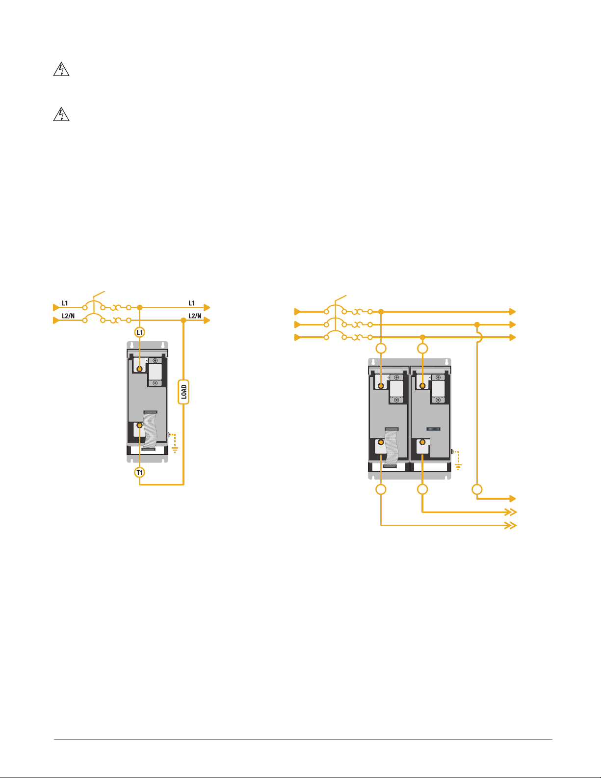
Wiring Overview 480V and 600V Units
The diagrams in this section indicate the locations of the line power, load, earth ground and control signal connections on 480V and 600V power controllers.
Single Phase, 60A to 210A
Cover Closed
M3
Cover Tipped Forward
M4
Port
2
M2
M1
Three-Phase, Two-Leg, 60A to 210A
Covers Closed
M3
M4
L1
T1
Covers Tipped Forward
L1
L3
Port
2
M1
M2
T1
T3
Watlow - ASPYRE 60A to 210A Power Controller • 22 • Chapter 3 Wiring 480V and 600V Units
Page 23
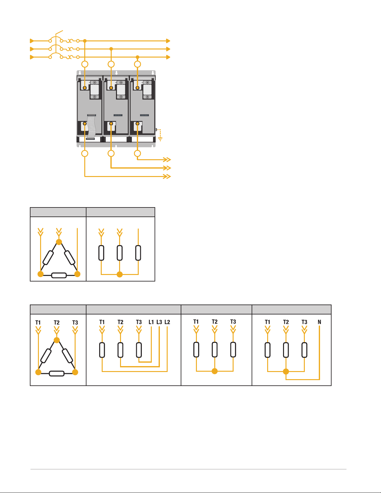
Three-Phase, Three-Leg, 60A to 210A
Covers Tipped Forward
L2
L3
T3
T2
M4
Port
Covers Closed
M3
L1
2
M1
T1
Wire Selection, Prep and Torque
This section lists the recommended cable and bus bar sizes for line power, load, earth ground and control signal
connections. There are also recommendations for insulation stripping and termination torque.
Line Power and Load Cable Size and Termination
Model Cable Size Bolt
Cable Termination
UL® Listed (ZMVV)
DT_ _ _-060... 6 AWG (16mm2)
DT_ _ _-090... 3 AWG (25mm2)
DT_ _ _-120... 1 AWG (50mm2)
DT_ _ _-150... 1/0 AWG (70mm2)
M6
Terminal Copper
Tube Crimp Lug
M8DT_ _ _-180... 2/0 AWG (70mm2)
DT_ _ _-210... 4/0 AWG (120mm2)
Ground Cable Size
Model Wire Size Bolt
DT_ _ _-060... 10 AWG (6mm2)
DT_ _ _-090... 8 AWG (10mm2)
DT_ _ _-120...
6 AWG (16mm2)DT_ _ _-150...
M6
DT_ _ _-180...
DT_ _ _-210... 4 AWG (25mm2)
Control and Signal Cable Size
Range: 22 to 14 AWG (0.50 to 1.5mm2)
Recommended: 18 AWG (0.75mm2)
Watlow - ASPYRE 60A to 210A Power Controller • 23 • Chapter 3 Wiring 480V and 600V Units
Page 24
Insulation Stripping and Torque
To insure proper connections, but minimize hazardous exposure of conductors, strip the correct amount of insulation from each cable.
Insulation Stripping
Load & Line Power
Ground
Control and Signal
Control Signal and Ground Torque
Control & Signal
Ground
Line Power and Load Torque
Model Connector Type Wire Termination Proper Torque
DT_ _ _-060...
DT_ _ _-120...
DT_ _ _-150...
DT_ _ _-210...
Per crimp lug requirements
Per crimp lug requirements
0.24 in. (6mm)
4 in.-lb. (0.11 Nm)
70.8 in.-lb. (8.0 Nm)
Bus Bar with M6 bolt
UL® Listed (ZMVV) Copper Tube Crimp Lug
Bus Bar with M8 bolt 141.6 in.-lb. (16.0 Nm)DT_ _ _-180...
70.8 in.-lb. (8.0 Nm)DT_ _ _-090...
Terminal Strip Connections
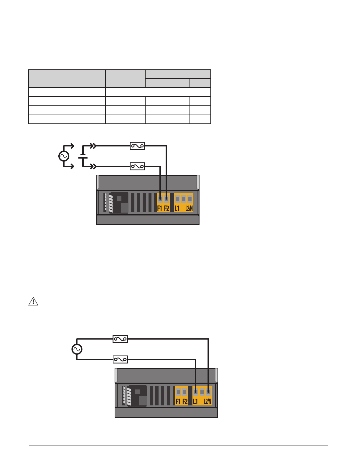
This section lists and describes the terminal strip connections.
M1 Terminal Connections (90A to 210A only)
M1 Function Description
F1
Power input for fan
F2 - For DC fans, line or neutral for AC fans
M2 Terminal Connections (DT1 and DT2 only)
M2 Function Description
L1 Auxiliary power input Line 1
- Not used
L2/N Auxiliary power input Line 2 or neutral on single-phase units
M3 Terminal Connections
M3 Function Description
1 10V power supply common For digital inputs and potentiometer
2 Digital input common Reference to 10V power supply common, if necessary
3 Digital input 2
4 Digital input 1
5 Analog input 1+ Set point signal input
6 Analog common - For analog in 1 and 2
7 +10V power supply For dry contact digital inputs or potentiometers for analog inputs
8 Analog input 2+ Alternate set point, external feedback or current limit (DT1 and DT3)
9 Not used
10 Retransmit output+
+ For DC fans, line or neutral for AC fans
See “Congurable Digital Inputs (Digital Input 1 and Digital Input 2)” on
page 26
Watlow - ASPYRE 60A to 210A Power Controller • 24 • Chapter 3 Wiring 480V and 600V Units
Page 25
M3 Function Description
-
+
11
Port 1 Modbus® RTU RS-485
12 Connect to A- on USB-to-485 adapter
13 Analog common For retransmit output
14
Alarm output
15 NC (normally closed contact)
16 NO (normally open contact)
M4 Terminal Connections for Modbus® RTU Secondary Communication Option
M4 Function Description
1 +24VDC input
2 Common For 24VDC input
3 Not used
4
Port 2 Modbus® RTU RS-485*
5 Connect to B+ on USB-to-485 adapter
*Connect 485 signal here only on units with second Modbus® RTU 485 communications port option. Connecting
signal here on units with other wired communications options will interfere with the operation of that option.
Connect to B+ on USB-to-485 adapter
C (common)
Supplemental power for applications that use both analog retransmit and
the second communication port (other than Modbus® RTU.)
Connect to A- on USB-to-485 adapter
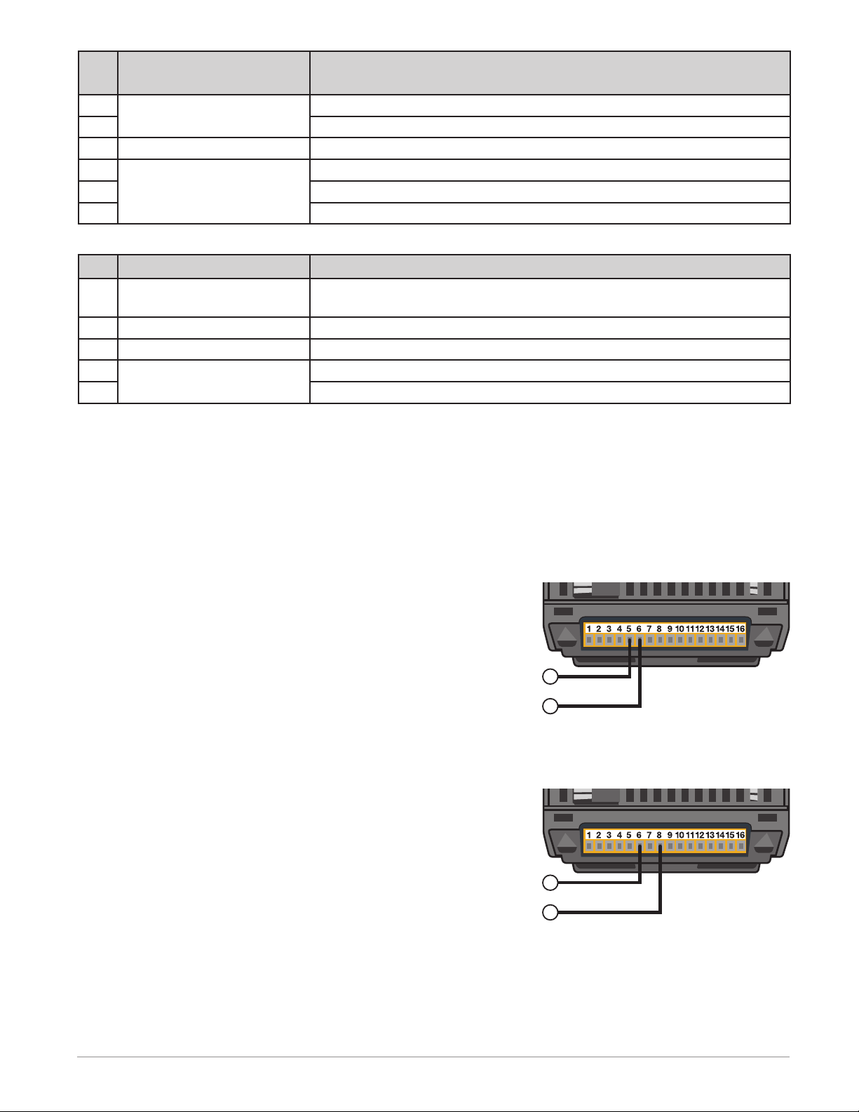
Connecting Control Signals
This section shows how to connect control signals to the M3 terminals.
Set Point (Analog Input 1)
To control the power to the load with a device such as
a temperature controller, connect the control signal to
analog input 1.
This input accepts current (0 to 20mADC, 4 to 20mADC),
voltage (0 to 10VDC) and potentiometer (0 to 10,000Ω)
signals. Congure the power controller to recognize the
signal on the hardware menu; see “Analog In 1 [Signal
Type]” on page 65.
Analog Input 1 Wiring on M3 Terminals (Top View)
+
Analog Input 1
Set Point, Feedback or Current Limit (Analog Input 2)
What this input does is user-congurable. Connect an analog signal that indicates:
• An alternate set point signal
• Measured power, voltage or current for use as feedback
• In models with the current limit option: the maximum
current to the load (current limit set point)
This input accepts current (0 to 20mADC, 4 to 20mADC),
voltage (0 to 10VDC) and potentiometer (0 to 10,000Ω)
signals. Congure the power controller to recognize the
signal and how the power controller uses it on the hardware menu; see “Analog In 2 [Signal Type]” on page 66
and “Analog In 2 Function” on page 66.
Analog Input 2 Wiring on M3 Terminals (Top View)
-
Analog Input 2
Watlow - ASPYRE 60A to 210A Power Controller • 25 • Chapter 3 Wiring 480V and 600V Units
Page 26
Configurable Digital Inputs (Digital Input 1 and Digital Input 2)
Normally Closed Contact
What these inputs do is user-congurable. Connect digital signals to:
• Enable the power controller to output power to the load
• Change the feedback to voltage
• Change whether the local or remote set point is used
• Change the ring type to phase angle
Congure how the power controller uses these signals on the hardware menu; see “Digital In 1 Function” on page
68 and “Digital In 2 Function” on page 69.
Digital Input Wiring on M3 Terminals (Top View)
Digital Input 2
Digital Input 1
External DC Supply
–
+
Digital Input 2
Digital Input 1
NOTE! If you use the +10VDC power supply to provide the input signal, connect the 10VDC common (M1 ter-
minal 1) to the digital input common (M3 terminal 2).
Alarm Outputs
Connect to the relay contacts so that alarms in
the power controller can be detected or enun-
ciated by external devices. Congure which
alarms cause the relay to energize with the
hardware menu; see “Alarm Function” on page
65.
Alarm Wiring on M3Terminals (Top View)
Alarm Output
NO
Normally Open Contact
NC
C
Common
Retransmit Option
Connect the analog output to an external device
so it can monitor or record set point, current,
voltage, or actual power.
Retransmit Wiring on M3 Terminals (Top View)
Which data is retransmitted and the scaling of
the output are user-congurable on the hardware menu; see “Retransmit (Models with
Retransmit Output
C
Common
Retransmit)” on page 77, “Retransmit Type
Retransmit
(Models with Retransmit)” on page 78 and
+
“Retransmit Scale (Models with Retransmit)” on
page 78.
If using the retransmit feature and any Ethernet
protocol or Probus, connect an external power
to the supplemental 24VDC input.
Watlow - ASPYRE 60A to 210A Power Controller • 26 • Chapter 3 Wiring 480V and 600V Units
Supplemental Power Wiring on M4 Terminals (Front View)
–
+24VDC Input
+
2
1
Page 27
Communication Connections
All models include at least one RS-485 communication port. Some models include a second communication port.
Connect these ports to allow other equipment to monitor, operate or congure the power controller. The communication protocols have adjustable software settings on the Communication menu see the “Menu Listing” on
page 49.
RS-485, Modbus® RTU Wiring on M3 Terminals (Top View)
A-
RS-485
B+
Accessing the Optional Second Communication Port
The second communication port, if present is located near the center of the front cover of the module with the
user interface.
Communication Options
Model Communication Option Connector Type
DT_ _ _-_ _ _ _ _-_0_ _ _ No additional port N/A
DT_ _ _-_ _ _ _ _-_1_ _ _ Modbus® TCP (Ethernet) RJ-45
DT_ _ _-_ _ _ _ _-_2_ _ _ Modbus® RTU (2nd RS485 port)* Removable Screw Terminal (M4)
DT_ _ _-_ _ _ _ _-_3_ _ _ Probus DP DB9
DT_ _ _-_ _ _ _ _-_4_ _ _ Pronet RJ-45
DT_ _ _-_ _ _ _ _-_5_ _ _ EtherNet/IP™ RJ-45
*Connect 485 signal here only on units with second Modbus® RTU 485 communications port option. Connecting
signal here on units with other wired communication options will interfere with the operation of that option.
M4
RJ-45
DB9
Watlow - ASPYRE 60A to 210A Power Controller • 27 • Chapter 3 Wiring 480V and 600V Units
Page 28
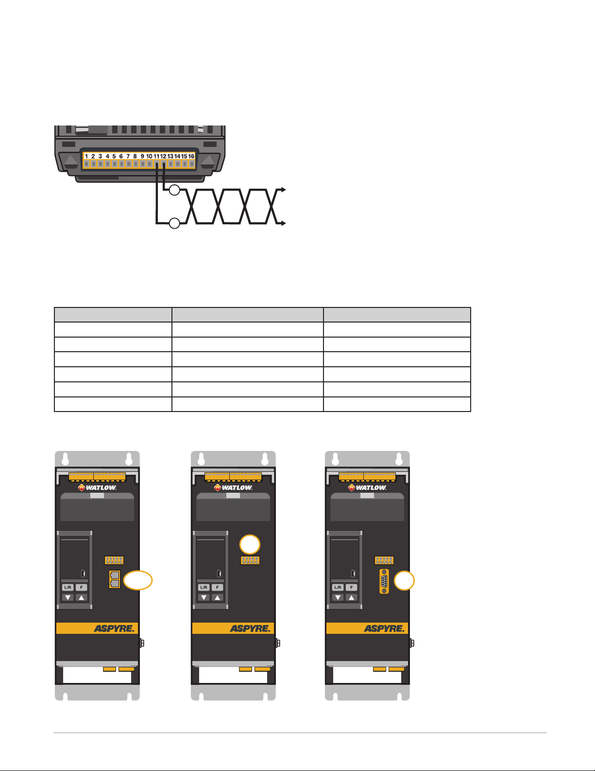
Powering the Cooling Fans
Connect power of the appropriate voltage for the cooling fans. For AC fans install fuses on each hot leg (not required for single-phase neutral). Use 2A class CC fuses rated for 600VAC similar to Cooper Bussman® LP-CC Series.
Supply power for one fan per switched leg for 90A to 210A models (60A models have no fans).
Cooling Fan Voltage and Power Per Fan
Fan Voltage Option Fan Voltage
DT_ _ _ -_ _ _ _ _-0_ _ _ _ No Fan
DT_ _ _ -_ _ _ _ _-1_ _ _ _ 120VAC 15W 30W 45W
DT_ _ _ -_ _ _ _ _-2_ _ _ _ 240VAC 16W 32W 48W
DT_ _ _ -_ _ _ _ _-3_ _ _ _ 24VDC 12W 24W 36W
Fan Power Wiring on M1 Terminals (Bottom View)
Power Requirement
DT1... DT2... DT3...
–
Fan Power
+
Fuses (for AC Fans)
Connecting the Auxiliary Power (DT1 and DT2 Only)
The auxiliary power input supplies the controller’s electronics. The voltage supplied at M2 terminal L1 must be
synchronized with the phase that is connected to the L1 line power terminal. The auxiliary voltage is indicated
on the product identication label and encoded in the part number as the nominal voltage (character 9).
Install fuses on each hot leg (not required for single-phase neutral). Use 2A class CC fuses rated for 600VAC similar to Cooper Bussman® LP-CC Series.
NOTE! DT3 models supply power to the controller’s electronics internally from the line power connections
and the auxiliary power connector is not present.
Auxiliary Power Input on M2 Terminals (Bottom View)
Line 2 /Neutral
Auxiliary Power
Line 1
Watlow - ASPYRE 60A to 210A Power Controller • 28 • Chapter 3 Wiring 480V and 600V Units
Fuses
Page 29
Opening The Covers
WARNING: To prevent injury and loss of life, shut off power and ensure it cannot be restored while perform-
ing work with the covers open or removed.
AVERTISSEMENT : Pour éviter les blessures et les pertes de vie, couper l’alimentation électrique et s’assurer
qu’elle ne peut être restaurée pendant l’exécution du travail avec les couvercles ouverts ou enlevés.
To open the front cover to access line power, load and other connections:
1. Grip the cover by the handle .
2. Pull the cover rmly toward you and down.
Wiring the Line Power and Load
Line Power Connection Locations
The following illustrations indicate how to connect line power and loads.
Single-Phase Line Power and Load Wiring
Three-Phase. Two-Leg Line Power and Load Wiring
L1
L2
L3
L1 L3
T1
T3
L2
L1
L2
L3
Watlow - ASPYRE 60A to 210A Power Controller • 29 • Chapter 3 Wiring 480V and 600V Units
Page 30
Three-Phase, Three Leg Line Power and Load Wiring
L1
L2
L3
L1
T1 T2
L2
L3
T3
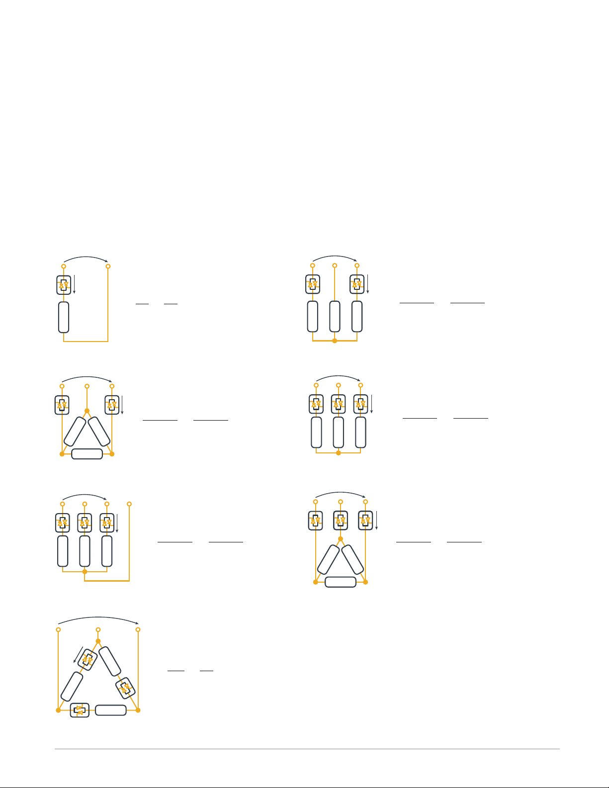
Three-Phase, Two-Leg Load Wiring Congurations
Delta Wye
L1
L2
L3
T3
L2
T1
T3
L2
T1
Three-Phase, Three-Leg Load Wiring Congurations
Delta Open Delta Wye Grounded Wye
Watlow - ASPYRE 60A to 210A Power Controller • 30 • Chapter 3 Wiring 480V and 600V Units
Page 31

4
Wiring 690V Units
WARNING: To avoid damage to property and equipment, injury and loss of life, adhere to applicable electrical codes and standard wiring practices when installing and operating this product. Failure to do so could result
in damage, injury and death.
AVERTISSEMENT! Pour éviter d’endommager la propriété et l’équipement, les blessures et la perte de vie,
respecter les codes électriques en vigueur et les pratiques de câblage standard au moment de l’installation et
de l’utilisation de ce produit. Dans le cas contraire, cela peut entraîner la mort, des blessures graves ou des
dommages.
WARNING: The installation must be protected by electromagnetic circuit breakers or by fuses. The semicon-
ductor fuses located inside the power controller are classied for UL® as supplementary protection for semicon-
ductor devices. They are not approved for branch circuit protection.
AVERTISSEMENT! L’installation doit être protégée par des disjoncteurs électromagnétiques ou des fusibles.
Les fusibles pour semi-conducteurs situés à l’intérieur du régulateur de puissance sont classés UL® comme protection supplémentaire pour les dispositifs pour semi-conducteurs. Ils ne sont pas approuvés pour la protection
des circuits de dérivation.
Wiring the ASPYRE Power Controller
This chapter describes how to select, prepare and attach power and signal wires to the power controller.
Good Wiring Practices
Follow good wiring practices to minimize the effects of interference from nearby equipment and the line power
on the operation of the power controller:
• Install an appropriately sized RC lter across contactor coils, relays and other inductive loads
• Use shielded twisted-pair cables for input, output and communication signals
• Route control and signal cables away from motors and other sources of electromagnetic interference and
not parallel to power cables
• Follow all local regulations applicable to electrical installations
NOTE: Use only copper cables and wires rated for use at 75°C or greater.
REMARQUE : N’utiliser que des câbles et des ls en cuivre pour l’utilisation à 75 °C ou plus.
Watlow - ASPYRE 60A to 210A Power Controller • 31 • Chapter 4 Wiring 690V Units
Page 32

Wiring Overview 690V Units
The diagrams in this section indicate the locations of the line power, load, earth ground and control signal connections on 690V power controllers.
Single Phase, 60A to 210A
Top & Bottom Covers O
L1
L/R F
M1
Center Cover Tipped Forward
M2
T1
Three-Phase, Two-Leg, 60A and 90A
Top & Bottom Covers O
L1 L2 L3
L/R F
M1
Center Cover Tipped Forward
M2
T1 T2 T3
Watlow - ASPYRE 60A to 210A Power Controller • 32 • Chapter 4 Wiring 690V Units
Page 33

Three-Phase, Three-Leg, 60A and 90A
Top & Bottom Covers O
L1 L2 L3
L/R F
M1
T1 T2 T3
Center Cover Tipped Forward
M2
Three-Phase, Two-Leg, 120A to 210A
Top & Bottom Covers O
T3L3T2
M1
L1
L2T1
L/R F
Center Cover Tipped Forward
M2
Watlow - ASPYRE 60A to 210A Power Controller • 33 • Chapter 4 Wiring 690V Units
Page 34

Three-Phase, Three-Leg, 120A to 210A
Top & Bottom Covers O
Center Cover Tipped Forward
T3L3T2
M2
M1
L1
L2T1
L/R F
Wire Selection, Prep and Torque
This section lists the recommended cable and bus bar sizes for line power, load, earth ground and control signal
connections. There are also recommendations for insulation stripping and termination torque.
Line Power and Load Cable Size and Termination
Model Cable Size Tool Strip Insulation Proper Torque
DT_ _ _-060... 6 AWG (16mm2)
DT_ _ _-090... 3 AWG (35mm2)
DT_ _ _-120... 1 AWG (50mm2)
DT_ _ _-150... 1/0 AWG (70mm2)
6mm Hex Key
Per terminal
block size
DT_ _ _-180... 2/0 AWG (70mm2)
DT_ _ _-210... 4/0 AWG (120mm2)
Ground Cable Size
Model Cable Size Tool Cable Termination Proper Torque
DT_ _ _-060... 8 AWG (10mm2)
DT_ _ _-090...
DT_ _ _-150...
DT_ _ _-180...
DT_ _ _-210...
6 AWG (16mm2)DT_ _ _-120...
4 AWG (25mm2)
M6 Wrench
UL® Listed (ZMVV)
Tube Crimp Lug
Control and Signal Cables
Size Range Recommended Size Strip Insulation Proper Torque
22 to 14 AWG (0.50 to 1.5mm2) 18 AWG (0.75mm2) 0.24 in. (6mm)
177 in.-lb.
(20.0 Nm)
70.8 in.-lb.
(8.0 Nm)
4 in.-lb.
(0.11 Nm)
Watlow - ASPYRE 60A to 210A Power Controller • 34 • Chapter 4 Wiring 690V Units
Page 35

Insulation Stripping and Torque
To insure proper connections, but minimize hazardous exposure of conductors, strip the correct amount of insulation from each cable. For ground strip cable insulation per crimp lug requirements. For load, line power and
control and signal cables see tables above.
Removing the Covers
WARNING: To prevent injury and loss of life, shut off power and ensure it cannot be restored while perform-
ing work with the covers open or removed.
AVERTISSEMENT : Pour éviter les blessures et les pertes de vie, couper l’alimentation électrique et s’assurer
qu’elle ne peut être restaurée pendant l’exécution du travail avec les couvercles ouverts ou enlevés.
To remove the top cover (line power) or bottom cover (load connections):
1. Loosen and remove the fasteners (1 ea. single-phase, 2 ea. three-phase).
2. Tilt the cover toward you and remove it.
To access the M2 connector:
• After removing the top and bottom covers, tilt the center cover forward.
Connecting Control Signals
This section shows how to connect control signals to the M1 and M2 terminal strips.
M1 Terminal Connections
M1 Function Description
1
Alarm output
2 C (common)
3 NC (normally closed contact)
4 Analog input 2+ Alternate set point, external feedback or current limit (DT1 and DT3)
5 Digital input 2
6 Digital input 1
7
Port 1 Modbus® RTU RS-485*
8 Connect to A- on USB-to-485 adapter
Watlow - ASPYRE 60A to 210A Power Controller • 35 • Chapter 4 Wiring 690V Units
NO (normally open contact)
See “Congurable Digital Inputs (Digital Input 1 and Digital Input 2)” on
page 26
Connect to B+ on USB-to-485 adapter
Page 36

M1 Function Description
9 +10V power supply
10 10V power supply common
11 Analog common - For analog in 1 and 2
12 Analog input 1+ Set point signal input
13 Digital input common Reference to 10V power supply common, if necessary
14 Not Used
15
Power input for fan
16 - For DC fans, line or neutral for AC fans
17 Not used
18 Auxiliary power input Line 1
19 Not used
20 Auxiliary power input Line 2 or neutral on single phase units
M2 Terminal Connections
M2 Function
+24VDC supplemental power for applications that use both analog retransmit and the sec-
1
ond communication port (other than Modbus® RTU)
2 Unused
3 Retransmit output+
4 Common for retransmit and 24VDC input
For dry contact digital inputs or potentiometers for analog inputs
+ For DC fans, line or neutral for AC fans
Secondary Modbus® RTU Terminal Connections*
Function Description
A+
Port 2 Modbus® RTU RS-485
B- Connect to A- on USB-to-485 adapter
*Connect 485 signal here only on units with second Modbus® RTU 485 communications port option. Connecting
signal here on units with other wired communications options will interfere with the operation of that option.
Connect to B+ on USB-to-485 adapter
Set Point (Analog Input 1)
To control the power to the load with a device
such as a temperature controller, connect the control signal to analog input 1.
This input accepts current (0 to 20mADC, 4 to
20mADC), voltage (0 to 10VDC) and potentiometer (0 to 10,000Ω) signals. Congure the power
controller to recognize the signal on the hardware
menu; see “Analog In 1 [Signal Type]” on page
65.
Analog Input 1 Wiring on M1 Terminals
1 2 3 4 5 6 7 8 9 10 11 12 13 14 15 16 17 18 19 20
11 12
–
Analog Input 1
+
Watlow - ASPYRE 60A to 210A Power Controller • 36 • Chapter 4 Wiring 690V Units
Page 37

Set Point, Feedback or Current Limit (Analog Input 2)
14 15 16 17 18 19 20
17 18 19 20
What this input does is user-congurable.
Connect an analog signal that indicates:
• An alternate set point signal
• Measured power, voltage or current
for use as feedback
• In models with the current limit
option: the maximum current to the
load (current limit set point)
This input accepts current (0 to 20mADC,
4 to 20mADC), voltage (0 to 10VDC) and
potentiometer (0 to 10,000Ω) signals.
Congure the power controller to recognize the signal and how the power controller uses it on the hardware menu; see
“Analog In 2 [Signal Type]” on page 66
and “Analog In 2 Function” on page 66.
Analog Input 2
Analog Input 2 Wiring on M1 Terminals
1 2 3 4 5 6 7 8 9 10 11 12 13 14 15 16 17 18 19 20
4
11
–
+
Configurable Digital Inputs (Digital Input 1 and Digital Input 2)
What these inputs do is user-congurable. Connect digital signals to:
• Enable the power controller to output power to the load
• Change the feedback to voltage
• Change whether the local or remote set point is used
• Change the ring type to phase angle
Congure how the power controller uses these signals on the hardware menu; see “Digital In 1 Function” on page
68 and “Digital In 2 Function” on page 69.
Digital Input Wiring on M1 Terminals
1 2 3 4 5 6 7 8 9 10 11 12 13
5
10 1396
1 2 3 4 5 6 7 8 9 10 11 12 13 14 15 16
5
136
–
Digital Input 2
Digital Input 1
Digital Input 2
Digital Input 1
External DC
Power Supply
+
NOTE! If you use the +10VDC power supply to provide the input signal, connect the 10VDC common (M1 ter-
minal 10) to the digital input common (M1 terminal 13).
Watlow - ASPYRE 60A to 210A Power Controller • 37 • Chapter 4 Wiring 690V Units
Page 38

Alarm Outputs
Connect to the relay contacts so that alarms in the
power controller can be detected or enunciated by
external devices. Congure which alarms cause the
relay to energize with the hardware menu; see
“Alarm Function” on page 65.
Alarm Wiring on M1 Terminals
1 2 3 4 5 6 7 8 9 10 11 12 13 14 15 16 17 18 19 20
2
3
1
Retransmit Option
Connect the analog output to an external device so it can monitor or
record set point, current, voltage, or actual power.
Which data is retransmitted and the scaling of the output are user-congurable on the hardware menu; see “Retransmit (Models with Retransmit)” on page 77, “Retransmit Type (Models with Retransmit)” on
page 78 and “Retransmit Scale (Models with Retransmit)” on page
78.
If using the retransmit feature and any of the Ethernet protocols or
Probus, connect an external power to the supplemental 24VDC input.
Alarm Output
NC
Normally Closed Contact
C
Common
NO
Normally Open Contact
Retransmit Wiring on M2 Terminals
1 2 3 4
1
4
3
Retransmit Output
C
Common
Retransmit
+
+24VDC Input
+
Communication Connections
All models include at least one RS-485 communication port. Some models include a second communication port. Connect these ports to allow
other equipment to monitor, operate or congure
the power controller. The communication protocols have adjustable software settings on the
Communication menu see the “Menu Listing” on
page 49.
RS-485, Modbus® RTU Wiring on M1 Terminals
1 2 3 4 5 6 7 8 9 10 11 12 13 14 15 16 17 18 19 20
8
7
A-
B+
RS-485
Watlow - ASPYRE 60A to 210A Power Controller • 38 • Chapter 4 Wiring 690V Units
Page 39

Accessing the Optional Second Communication Port
The second communication port, if present is located on a daughter card mounted on the back of the main electronics board. Tip the center cover forward and down to access the port.
Communication Options
Model Communication Option Connector Location on Daughter Card
DT_ _ _-_ _ _ _ _-_0_ _ _ No additional port N/A
DT_ _ _-_ _ _ _ _-_1_ _ _ Modbus® TCP (Ethernet) RJ-45 on right side
DT_ _ _-_ _ _ _ _-_2_ _ _ Modbus® RTU (2nd RS485 port) 2-pin connector on left side*
DT_ _ _-_ _ _ _ _-_3_ _ _ Probus DP DB9 connector on right side
DT_ _ _-_ _ _ _ _-_4_ _ _ Pronet RJ-45 on right side
DT_ _ _-_ _ _ _ _-_5_ _ _ EtherNet/IP™ RJ-45
*Connect 485 signal here only on units with second Modbus® RTU 485 communications port option. Connecting
signal here on units with other wired communication options will interfere with the operation of that option.
RJ-45
or DB9
RS-485
Powering the Cooling Fans
Connect power of the appropriate voltage for
the cooling fans. Install fuses on each hot leg
(not required for single-phase neutral). Use 2A
class CC fuses rated for 600VAC similar to Cooper
Bussman® LP-CC Series. Supply power for one
17W fan for all single-phase models and all 60A
and 90A models and two 17W fans for two- and
three-leg 120A to 210A models.
Cooling Fan Voltage
Model Voltage
DT_ _ _-_ _ _ _ _-0_ _ _ _ No Fan
DT_ _ _-_ _ _ _ _-1_ _ _ _ 120VAC
DT_ _ _-_ _ _ _ _-2_ _ _ _ 240VAC
DT_ _ _-_ _ _ _ _-3_ _ _ _ 24VDC
Fan Power
Fan Power Wiring on M1 Terminals
1 2 3 4 5 6 7 8 9 10 11 12 13 14 15 16 17 18 19 20
15 16
+
–
Fuses (for AC fans)
Watlow - ASPYRE 60A to 210A Power Controller • 39 • Chapter 4 Wiring 690V Units
Page 40

Connecting the Auxiliary Power
The auxiliary power input supplies the controller’s electronics. The voltage supplied at M1 terminal 18 must be
synchronized with the phase that is connected to the L1 line power terminal. The auxiliary voltage is indicated
on the product identication label and encoded in the part number as the nominal voltage (character 9).
Install fuses on each hot leg (not required for single-phase neutral). Use 2A class CC fuses rated for 600VAC similar to Cooper Bussman® LP-CC Series.
Auxiliary Power Input on M1 Terminals
1 2 3 4 5 6 7 8 9 10 11 12 13 14 15 16 17 18 19 20
18 20
Line 1
Line 2 /Neutral
Fuses
Wiring the Line Power and Load
Line Power Connection Locations
The following illustrations indicate how to connect line power and loads.
Single-Phase Line Power and Load Wiring
L/R F
Three-Phase Line Power and Load Wiring 60A and 90A
L/R F
Watlow - ASPYRE 60A to 210A Power Controller • 40 • Chapter 4 Wiring 690V Units
Page 41

Three-Phase Line Power and Load Wiring 120A to 210A
L/R F
Three-Phase, Two-Leg Load Wiring Congurations
Delta Wye
Three-Phase, Three-Leg Load Wiring Congurations
Delta Open Delta Wye Grounded Wye
Watlow - ASPYRE 60A to 210A Power Controller • 41 • Chapter 4 Wiring 690V Units
Page 42

Watlow - ASPYRE 60A to 210A Power Controller • 42 • Chapter 4 Wiring 690V Units
Page 43

5
Initial Setup
This chapter provides the information necessary to begin using your ASPYRE power controller.
The procedures below call for setting and verifying parameter settings. These parameters can be set via the
control panel or using the ASPYRE Congurator software. To learn more about how to use the control panel to
access and set parameters on the menus; see “Menu Navigation” on page 48.
Using the ASPYRE Configurator Software
The power controller can be set up and monitored via the menus using the on-board keypad and display or using
a computer running the ASPYRE Congurator software. The ASPYRE Congurator software is available on the
website.
To use the software:
1. Download and run the ASPYRE Congurator software instal-
lation le and follow the on-screen instructions.
2. Connect a USB cable (Watlow p/n 0219-0480-0000) between a USB host port on the computer and the micro USB
port on the front of the ASPYRE power controller.
3. Wait for the communications port installation to complete.
4. Launch the ASPYRE Congurator software
5. From the Setting menu, choose Serial Port.
6. Choose the communications port and click OK.
7. For a single-phase model select ASPYRE or for a 2-leg or
3-leg model, select ASPYRE 3PH.
8. Click Upload from unit.
9. Click Read.
10. In the Selection list under power controller click the menu to access.
ASPYRE Congurator Software
Configuring the ASPYRE Power Controller
The ASPYRE power controller includes many advanced features. You can learn more about these in the Features
chapter of the manual. In order to get the optimum performance in your application, be sure to verify or adjust
these settings before beginning operation:
Initial setup:
1. Nominal current and voltage
2. Firing type
3. Feedback type
4. Input for power request / set point
5. Enable input, if used
6. Current limit (DT1 and DT3 models), if used
Watlow - ASPYRE 60A to 210A Power Controller • 43 • Chapter 5 Initial Setup
Page 44

Set Nominal Current and Voltage
In order for the power controller to function correctly, set the nominal line voltage and load current. To calculate the nominal load current see “Digits 6, 7 and 8, Amperage” on page 13. Otherwise it can be determined
empirically after completing the installation and other setup steps by applying 100% power and measuring the
resulting current.
On this menu... set this parameter... to the...
Setup Nominal V nominal line voltage (RMS)
1
Setup Nominal I nominal current (RMS), each leg of the load at 100% power
2
Set the Firing Type
Choose the ring type in order to optimize the performance of the load.
On this menu... set this parameter... to the...
Adv Setup Firing type of power switching appropriate for your load
Also on the Adv Setup menu set the parameters that adjust the behavior of the ring type you chose.
For... set this parameter... to the...
Phase Angle Soft Start Soft Start amount of time for the output to ramp to the set point
Burst Fire Start Ramp Start Ramp number of half cycles over which each burst should ramp
Burst Fire
Burst Fire Start Ramp
Burst Fire Delay Trigger
BF Strt Rmp Delay Trigger
Burst Fire Delay Trigger
BF Strt Rmp Delay Trigger
Zero Crossing Cycle Time duration of each on-off cycle
Half Cycle Safety Ramp
Min Cycles fewest number of cycles the output should be on or off
Delay ring delay from zero cross in degrees
Half Cycles to Delay number of half cycles to which to apply the delayed ring
Safety Ramp
Duration
Safety Ramp Off
Time
amount of time for the output to ramp to the set point
minimum amount of off-time before ramping is needed
Set the Feedback
Choose the variable to use for feedback to optimize the performance of the application.
On this menu... set this parameter... to the...
Adv Setup Feedback type of measured feedback appropriate for your application
Configure the Input for Power Demand / Set Point
The signal to analog input 1 indicates the desired percent of full output the power control should deliver to the
load.
Congure the power request / set point signal:
On this menu... set this parameter... to the type of signal and range...
0-10 V / 10k pot (0 to 10 VDC or potentiometer)
Hardware Analog In 1
NOTE! This procedure assumes the analog input signal wiring, if used has been connected and that the signal
can be set to various values as needed to perform the procedure. See “Set Point” on page 79.
Watlow - ASPYRE 60A to 210A Power Controller • 44 • Chapter 5 Initial Setup
4-20mA (4 to 20 mADC)
0-20mA (0 to 20 mADC)
Page 45

Configure the Enable Input
By default digital input 1 is used to enable the power controller.
To verify that digital input 1 is congured to enable the power controller:
• On the Hardware menu verify that Digital In 1 Function is set to Enable.
NOTE! If the power controller is used to switch power on and off simply following an on-off or time propor-
tioned signal, that signal can be connected to the enable input and the set point can be set to 100%.
Configure the Current Limit
For models with this option the current limit feature prevents the current from exceeding the user-set current
limit. As the current approaches the limit, the power controller decreases its output to avoid exceeding the current limit. The current limit set point can be set with the I Limit parameter or by an analog input.
CAUTION: This procedure must be performed only by qualied persons.
ATTENTION : Cette procédure ne doit être effectuée que par le personnel qualié.
CAUTION: This procedure requires turning on full power to the load. This should only be performed once the
installation is complete and when it is safe to provide full power.
ATTENTION : Cette procédure nécessite la mise sous tension totale de la charge. Cela ne doit être effectué
qu’une fois l’installation terminée et lorsque la puissance maximale peut être fournie en toute sécurité.
To limit the current using the parameter setting:
1. On the Hardware menu set I Limit Local / Remote to Local.
2. On the Operator menu set I Limit to 0%.
3. Enable the power controller and set the power demand set point to 100%.
4. Gradually increase the current limit set point until the RMS current is at the maximum desired value.
5. Disable the power controller.
To limit the current using the signal to analog input 2:
1. On the Hardware menu set Analog In 2 for the type of signal and range:
0 to 10 VDC or 10k potentiometer
4 to 20 mADC
0 to 20 mADC
2. On the Hardware menu set the Analog In 2 Function to I Limit.
3. On the Hardware menu set the I Limit Local / Remote to Analog In 2.
4. Set the signal to the analog input to the minimum value (typically 0 V).
5. Enable the power controller and set the power demand / set point to 100%.
6. Gradually increase the signal to the analog input until the RMS current is at the maximum desired value.
7. Disable the power controller.
0-10 V / 10k
4-20mA
0-20mA
Watlow - ASPYRE 60A to 210A Power Controller • 45 • Chapter 5 Initial Setup
Page 46

NOTE! this procedure assumes the analog input signal wiring, if used has been connected and that the signal
can be set to various values as needed to perform the procedure. See “Set Point, Feedback or Current Limit
(Analog Input 2)” on page 25.
Watlow - ASPYRE 60A to 210A Power Controller • 46 • Chapter 5 Initial Setup
Page 47

6
Operation
This chapter describes how to operate the controller using its control panel interface, how to access and navigate the menus and how to interpret the indicators and alarm messages.
Control Panel
The control panel is located on the front of the power controller. The display indicates the alarms, input and
output signals, and by navigating the menus with the keypad, provides access to the conguration parameters.
Iout0.0A
SP 100%
Output Current RMS Output Voltage (RMS)
On the home page the keys are used as follows:
Press... to...
Function Scroll through the parameters on the home page
Local / Remote Switch between local and remote set point for power demand
Up Increment power demand set point when set to local
Down Decrement power demand set point when set to local
Vout0.0V
SP 100%
Pout0%
SP 100%
Output Power
(Average)
Aux High
ALARM
Alarms
+
To view the status parameters:
• Press function once to advance from one parameter to the next
To set the set point locally:
1. Press local / remote (Note: indicator 1 ashes steadily when set point is set locally.)
2. Use down and/or up to set the local set point.
Watlow - ASPYRE 60A to 210A Power Controller • 47 • Chapter 6 Operation
Press and hold for about two seconds to access the menus
Page 48

Menu Navigation
The menus are accessible using the control panel keypad and display.
Home
Page
Choose
Menu
Enter Password Choose Parameter Edit Parameter
+
(~2 sec.)
(wrong password)
(~2 sec.)
+
To access a menu and edit a setting:
1. Press and hold local / remote and function together + until the upper display ashes Menu.
2. Press up to choose the menu. (Press down if you overshoot the menu you want.)
3. Press function to advance to the password prompt.
4. Use up and/or down to set the password (see the table).
5. Press function to enter the password and advance to the rst parameter on the menu.
6. Press up to advance to the next parameter and repeat to reach the desired parameter.
7. Press function to start editing the parameter. The parameter name ashes in the upper display.
8. Use up and/or down to change the parameter setting.
9. Press function to stop editing the parameter. The parameter name stops ashing.
10. Press and hold local / remote and function together + for about two seconds to exit the menus.
Menu Password Parameters Used To...
Operator 0 View measured values and basic settings including current, voltage and set point
Setup 2 Congure the power controller for the load
Adv Setup 10
Hardware 5
Comm 3 Congure communication parameters
Monitor 0
Congure power switching, closed-loop control of power and adjustable settings for
data logging and heater bakeout
Congure the functions of the analog and digital inputs and outputs, and the re-
transmission parameters
View the states of digital inputs, values of analog inputs and information about the
power controller such as serial number and software version
Watlow - ASPYRE 60A to 210A Power Controller • 48 • Chapter 6 Operation
Page 49

Menu Listing
Aux High
ALARM
The table below lists the parameters found on each menu. See “Parameter Reference” starting on page 65 for
descriptions and the other details of each parameter.
Operator Setup Advanced Setup Hardware Communication Monitor
Set Point Out Scale Firing Analog In 1 Port 1 Baud Digital In 1
V Output I Limit
I Output Nominal V Soft Start Analog In 2 Function Port 2 Baud Enable
Leg 1 I Output1Nominal I Safety Ramp Off Time Digital In 1 Function Port 2 Access Set Point Source
Leg 2 I Output1Soft Start Safety Ramp Duration Digital In 2 Function Watchdog Analog In 1
Leg 3 I Output1Remote SP Start Ramp Alarm Function Watchdog Reset Time Analog In 2
Power Delay I Limit Local / Remote2Wi-Fi Address
V Input Half Cycles to Delay2Retransmit
Frequency Cycle Time Retransmit Scale
Power Factor Feedback Retransmit Type
Load Ω Prop Band Power Startup Display Host Name Max Current
2
I Limit
Out Scale Prop Band Current
Nominal V Integral Current
Nominal I Htr Break Sensitivity MM/DD/YY
Shaded items are read only.
1
DT2 and DT3 models
2
DT1 and DT3 models with the current limit option
3
Models with corresponding options (retransmit, Ethernet, Wi-Fi and/or real-time clock)
2
Min Cycles Analog In 2 Port 1 Address Digital In 2
3
3
3
3
Integral Power Port 2 Address Aux Voltage
2
2
Htr Break Delay HH:MM:SS
Logging kW Real Time
Logging Interval kW Total
Heater Bakeout
Bakeout Ramp Time
Bakeout Current
Bakeout Off Time
Neutral Connected
2
2
2
2
1
Ethernet Address
Ethernet Subnet
Ethernet Gateway
Port 2 Serial Number
3
Wi-Fi
3
3
3
Version
Release
Unit Type
Max Voltage
SCR Temperature
3
3
kVA Real Time
Thermal Alarm Counter
Indicators (LEDs)
The four indicators on the control panel show the general state of the power controller.
Flashing Power output set locally or via communications
Local/Remote
1
Off Power output set remotely (via analog input)
On Output enabled
Enable
2
Off Output disabled
Communication Flashing Active communications
3
On Active alarm
Alarm
4
Off No alarm
Watlow - ASPYRE 60A to 210A Power Controller • 49 • Chapter 6 Operation
Page 50

Alarms and Messages
The power controller display indicates certain modes of operation and alarms by ashing a message on the top
display.
Alarm or Message DT1 DT2 DT3 Description
Aux High X X X Aux voltage too high
Aux Line Loss
Aux Low X X X Aux voltage too low
Bakeout X X Heater bakeout function is active
Heater Break X X X Heater break alarm
I Limit X X Output reduced by current limit feature
PH Loss X One or more phases of the line power are disconnected
SD Card Error X X X SD card error
SCR Short X X X Shorted SCR causing output to be on continuously
SCR Over Temp X X X Thermal switch over temperature
Unbalance Load X X One or more legs of the load are open
Watchdog X X X Communication watchdog error
X X X Auxiliary power is not detected
X Line power not detected
Watlow - ASPYRE 60A to 210A Power Controller • 50 • Chapter 6 Operation
Page 51

7
Using ASPYRE Configurator
This chapter explains how to use the ASPYRE Congurator software as an alternative to using the power controller’s keypad and display for viewing and setting parameters as well as the advanced features not available via
the power controller’s onboard user interface.
Overview
This section describes the scope and intent of the ASPYRE Congurator software.
Typical Uses
The software may be used during commissioning to set and make a record of settings that determine how the
power controller operates and performs; to copy or clone the setup or one power controller to another; on a
day-to-day basis to monitor operation and power usage; if necessary, to examine performance in more detail to
determine if any corrective actions are needed; or to restore the setup of the power controller.
Communicating with Power Controllers
ASPYRE Congurator software can communicate with ASPYRE power controllers via USB or RS-485. When initially
commissioning the power controller it is convenient to connect a computer to the power controller via the USB
port located below the control panel’s display. The power controller’s electronics are powered by the computer
via the USB connection when the auxiliary line power is turned off. This makes it possible to examine and congure the power controller’s settings prior to applying power to the panel.
USB is designed to connect consumer electronics and peripheral devices such as cameras and keyboards to computers in home and ofce environments; it is not an industrial communications protocol. To continue communicating once the panel door is closed and line power is on, connect the computer to the power controller via the
RS-485 communications port. See “Communication Connections” on page 27.
Recipes
A recipe is a computer le which contains a setting for each user adjustable parameter in a power controller. A
recipe can be used to congure a power controller for a particular application or job. A recipe can be used to
copy the settings of one power controller to another. A recipe can be created by uploading the settings from a
power controller to the ASPYRE Congurator software and saving it as a le on the computer. A power controller
can be congured by downloading a saved recipe from the ASPYRE Congurator software to the power controller.
How To
This section provides step-by-step procedures for common tasks.
Communicate For the First Time
These procedures are for installing the software and establishing communications for the rst time.
To install ASPYRE Congurator:
1. Locate the installer:
• On www.watlow.com linked to the ASPYRE power controller product page. Download the installer to your
computer
• On the Controls Tools DVD ROM disk.
Watlow - ASPYRE 60A to 210A Power Controller • 51 • Chapter 7 Using ASPYRE Configurator
Page 52

2. Double-click the installer program.
3. Follow the on-screen instructions to complete the installation.
To communicate with a power controller:
1. For the direct USB connection:
• Connect the USB cable (Watlow p/n 0219-0480-0000)
between the computer and the micro USB connector
between the display and keypad on the ASPYRE power
controller’s control panel.
• Wait for the USB driver to install, if necessary.
2. For an RS-485 connection:
• Connect the computer to the ASPYRE power controller.
See “Communication Connections” on page 27. For
most computers a USB-to-485 converter is required
(Watlow p/n 0847-0326-0000).
3. Launch the ASPYRE Congurator software.
4. Select:
• ASPYRE to communicate with a single-phase
power controller
• ASPYRE 3PH to communicate with a three-phase
power controller (two or three switched legs)
5. From the Setting menu, choose Serial Port.
6. For Port, select the COM port that is connected to
the power controller (see the note below).
7. To verify communications, click Test.
8. Click OK.
NOTE! There are several ways to determine which port is connected to the power controller. You can look in
the Windows® Device Manager under Ports (COM & LPT) for the COM port named “LPC USB VCOM Port (COMx)”
where x is the port number. You can also disconnect the USB cable from the computer, run ASPYRE Congurator
and note the ports available in the list on the Serial Port dialog, then close ASPYRE Congurator, reconnect the
USB cable and run the program again; the port that did not appear previously is the correct one.
Using ASPYRE Configurator
These procedures are for using the software once communication has been set up. They assume the software has
been installed and the COM port and model type (ASPYRE or ASPYRE 3PH) have already been selected.
To view or save a power controller’s settings using
the Simple view:
1. Click Simple, if not already on the simple
view.
2. Click Upload from unit.
3. Set the address, if necessary.
4. Click READ.
5. Wait for the software to read the parameter
settings.
6. Click OK.
Watlow - ASPYRE 60A to 210A Power Controller • 52 • Chapter 7 Using ASPYRE Configurator
Page 53

7. If desired, to save the settings in a recipe le:
• Click Save.
• Name the recipe.
• Click Save.
NOTE! In the simple view, the parameter values are
only read from the power controller when the user uploads
the settings. Changes to parameter values are only set in
the controller when the user downloads the settings.
To edit a setting in a recipe:
1. Click Simple, if not already on the simple view.
2. Click Open existing recipe.
3. Locate and select the recipe le and click Open.
4. Click OK.
5. Click the menu with the setting you want to change
(Setup, Advanced setup, Hardware or Communi-
cations).
6. Select the value you want to change.
7. Edit the value with the increment and decrement
buttons in the eld or type the new value and press the Enter key.
8. Repeat steps 5 to 7 for all the changes you want to make.
9. To save the settings in a recipe le:
• Click Save.
• Name the recipe.
• Click Save.
To download a recipe le into a power controller:
1. Click Simple, if not already on the Simple view.
2. Click Open existing recipe.
3. Locate and select the recipe le and click Open.
4. Click OK.
5. Click Download to unit.
6. Set the address, if necessary.
7. Click SEND.
8. Wait for the software to write the parameter settings.
9. Click OK.
To monitor a power controller with the Test view:
1. Click Test, if not already on the test view.
2. Click Connect.
To log in on the test view to change the digital input and analog
input functions:
1. Click the Access Level value (zero when logged out).
2. Type the password: 1111.
3. Click OK.
Watlow - ASPYRE 60A to 210A Power Controller • 53 • Chapter 7 Using ASPYRE Configurator
Page 54

To log out the test view:
1. Click the Access Level value.
2. Click Log out.
3. Click OK.
To view data on the scope:
1. Click Test, if not already on the test view.
2. Click Connect.
3. Click Load Analyzer.
4. For each of up to three channels (Ch 1 to Ch 3):
• With PV1 choose the value to monitor
• Select Show.
• Click the color swatch to change the color
• Click the button to turn the channel on.
To reset the power totals:
1. Click Test, if not already on the test view.
2. Click Connect.
3. Click Reset Totals.
4. Click Yes.
Setting Up and Using Data Logging
To set up data logging:
1. Click Test, if not already on the test view.
2. Click Connect.
3. Click Data Log.
4. In the Data Log window ensure the slider
is set to Log Enabled.
5. Click Set Time.
6. Set the date and time and close the date/
time window.
7. Set Log Time to the number of seconds
between records.
8. Click Connect.
9. Click Cong.
10. For up to ten parameters to log:
• Click + to add a parameter to the list
• In a row in the list either:
Type a parameter’s Modbus® address in
the Par eld
OR
Select the parameter from the drop
down list in the Name eld
11. Click Save to send the parameter list to the controller
12. Click OK when prompted that the download is complete.
13. Click Close.
Watlow - ASPYRE 60A to 210A Power Controller • 54 • Chapter 7 Using ASPYRE Configurator
Page 55

14. Click Disconnect.
15. Close the Data Log window.
To retrieve a data log le from the power controller:
1. Click Test, if not already on the test view.
2. Click Connect.
3. Click Data Log.
4. Click Connect.
5. Select a le from the list.
6. Click Download.
7. Select a location and click Save.
8. Wait for the le to download. The progress is indicated at the bottom of the Data Log window.
9. Click OK when prompted that the download is complete.
10. To delete the log le from the controller memory, if desired, click Delete File.
11. Click Disconnect.
12. Close the Data Log window.
To view a data log le after downloading it:
1. Click Test, if not already on the test
view.
2. Click Data Log.
3. Click Data Explorer.
4. Click Open.
5. Locate and open the data log le.
6. If desired, click Graph to view the
data on a graph.
Watlow - ASPYRE 60A to 210A Power Controller • 55 • Chapter 7 Using ASPYRE Configurator
Page 56

Reference
This section provides explanations of the features found in the ASPYRE Congurator Software.
Program Window
Main Menu
Access these menus.
File menu
• Exit—close the program
Setting menu
• Language—open the Settings dialog to the language section
• Serial Port—open the Settings dialog to the serial
port section
• Option—open the Settings dialog to the options
section
? (Help) menu
• Message Log—opens the message view
• About—displays the About dialog with the program name and version and Watlow contact
information
View selector
Select the view to use:
• HOME—the default view
• ASPYRE—access the Simple and Test views for a single-phase power controller
• ASPYRE 3PH—access the Simple and Test views for a three-phase power controller
• MSG—use the tools for monitoring and analyzing serial communication between the computer and the power controller.
Status Bar
Indicates information such as time and date, communications port and
baud rate.
Simple view
Use this view to create, save, upload and download recipes, saved sets
of parameters settings. You can also use this view to see the settings in
a controller.
Access this view by selecting ASPYRE for a single-phase power controller or ASPYRE 3PH for a three-phase power controller and clicking the
Simple tab below the main menu, if not already selected.
NOTE! The parameter values are not updated continuously. They
are read only when you upload them from the power controller.
Click one of these options to open or create a recipe:
• Create a New recipe—create a recipe le with the standard
default settings
• Open existing recipe—open a previously saved recipe le
• Upload from unit—create a new recipe with the settings of the
currently connected power controller
Watlow - ASPYRE 60A to 210A Power Controller • 56 • Chapter 7 Using ASPYRE Configurator
Page 57

Click one of these options to manipulate the recipe:
1
• Close—close the recipe
• Save—save the recipe in a le
• Save as—save a copy of the recipe in a le
• Download to unit—set the parameters in the currently connected power
controller to the values in the recipe
• Print—print the recipe (see sample at left)
• Print report—print the recipe (see sample at left)
• Fast Settings—opens the setup wizard
Click a parameter menu to edit the corresponding parameters:
• Setup
• Advanced setup
• Hardware
• Communications
Click a parameter’s value to alter it.
NOTE! Changes to the values here affect the open
recipe only. To apply these changes to the power controller settings, download them to the power controller using
the Download to unit option.
Test view
Use this view to monitor and adjust the operation
of the power controller while communicating with
it in real time.
Access this view by selecting ASPYRE for a single-phase power controller or ASPYRE 3PH for a
three-phase power controller and clicking the Test
tab below the main menu, if not already selected.
Use these features to communicate with a power
controller:
• Communications status indicator—sweeps
clockwise when the software is communicating with a power controller and data is
updating continuously
• Connect/Disconnect button—click to start
or stop communication updates with the
power controller
• Address selector—set the address of the
power controller
• Access Level—click the value to log in or out. Password is “1111”.
• Fast Tune—when logged in, click to open the Fast Tune window.
• Port 2—set whether the secondary port is used only to read data or to read and write data (does not apply
to Modbus® RTU).
Use these features to congure and monitor the digital inputs:
• Digital input states and functions—show whether each input detects an open or closed circuit and the function the input performs
• Digital Input States and Function Selectors—set the function for each digital input. Click DI1 or DI2 to expand the options.
Watlow - ASPYRE 60A to 210A Power Controller • 57 • Chapter 7 Using ASPYRE Configurator
Page 58

View these indicators and elds for an overview or the conguration and status of the power controller.
Status and Setup Indicators:
• Digital input status—illuminated when the input
detects a closed circuit
• Enable indicator—illuminated when the power
controller is enabled
• Enable/Disable button—click to enable the power
controller if a digital input is not congured for
this function
• ON indicator—illuminated when there is demand
for the output to be on
• SC indicator—illuminated when there is a shorted
SCR error
• HB indicator—illuminated when there is a heater
break error
• TH indicator—illuminated when the heat sink is over temperature
• I Lim indicator—illuminated when the current being called for exceeds the current limit setting
• Unit Size—indicates the maximum rated current of the power controller
• Max Volt—indicates the maximum rated voltage for the power controller
• V Aux—indicates the voltage the auxiliary input is congured to use for powering the electronics
• Input Type1—indicates the type of signal analog input 1 is set to measure
• Input Type2—indicates the type of signal analog input 2 is set to measure
• DI1—indicates digital input 1’s function
• DI2—indicates digital input 2’s function
• Firing—indicates the ring type the power controller is set to use
• Feedback—indicates the type of feedback the power controller is set to use
• Data Log—indicates whether or not data is being logged by the power controller
NOTE! The data log indicator appears whether or not the connected power controller has the data logging
option.
Use these buttons to access the setup options:
• Communication—view and set the options for the communication ports and protocols
• Feedback—view and set what is used for feedback
• Firing—view and set the ring type and the associated
parameters
• Load Analyzer—view the graphing utility
• Data Log—click to open the Data Log window.
Watlow - ASPYRE 60A to 210A Power Controller • 58 • Chapter 7 Using ASPYRE Configurator
Page 59

Use these features to congure and monitor the analog inputs:
• Analog Input 1—click Ai 1 to view the signal type
• Input button (Local/Remote set point source selector)—click to
toggle between using the signal received at analog input 1 (remote) or the slider (local) to set the set point.
• Set Point—drag the slider, click the increment (+) or decrement
(-) buttons or click one of the three percentages (0%, 50% or
100%) to set the set point when the set point source is set to
local.
• Analog Input 2—click Ai 2 to view the signal type and function
Use these options to congure and monitor the power controller:
• Power Request—indicates the set point signal received
via analog input 1 as a percent of full scale or as set
with the reference slider
• Soft Start Time—indicates the time over which set point
changes are ramped
• Output Scaling—indicates the scaling applied to the set
point signal before it is used by the control loop
• Output Voltage (RMS), Output Power (RMS) and Output
Current (RMS) indicators—indicates the RMS current,
RMS voltage and RMS power output by the power controller
• Current Limit Set Point (RMS)—indicates the current
limit set point
• Bakeout button—click to view and set the heater bakeout feature options
• Load Calibration—set or view the nominal line voltage
and nominal load current settings for the application.
NOTE! The Load Calibration settings, Load Voltage and
Load Current dene 100% power for the load.
Energy Monitor—indicates power, power factor and energy usage
over time which may be reset with the Reset Totals button.
Data Log—use to congure the data logging feature if present
and retrieve data logs.
Fast Settings—opens the setup wizard.
Save Image—click to save a JPEG le with an image of the test
view.
Watlow - ASPYRE 60A to 210A Power Controller • 59 • Chapter 7 Using ASPYRE Configurator
Page 60

Load Analyzer (ASPYRE Scope)
Click Load Analyzer on the test
view to open this window.
For each of up to three channels
(Ch 1, Ch 2 and Ch 3) congure
a pen on the graph:
• On/Off button—click to
start trending data
• PV—choose the parameter
to trend
• Show—set this option to
display the trend
• Show Mark—set this option
to display data markers
along the trend in the
graph area
Live!—click to view a detailed
graph of the current in the Live!
window.
Use the History options to control the movement of the chart
• Scroll left—click to move the chart left to view more recent data
• Stop/Play—click to toggle chart movement on and off
• Scroll right—click to move the chart right to view older data
Use the Actions to:
• Clear—click to clear the data from the graph
• Save—click to save a JPEG image of the ASPYRE Scope window with the current trends
• Export—click to open a window and that includes the trend graph and table with the currently displayed
data that can be saved as a JPEG or exported to a CSV le.
Use the X – Scale settings to adjust the horizontal (time) axis:
• Min—set the number of minutes of data displayed
• Sec—set the number of seconds of data displayed
• Filter—set this option to lter the data
Use the Y – Scale settings to adjust the vertical (percent of full scale) axis
• Max—set the maximum value for the vertical axis
• Reset—click to reset the vertical axis scaling
NOTE! Use the increment (up arrow) and decrement (down arrow) buttons to adjust the x and y scales. Nu-
meric entry does not allow the full range of values to be set.
Watlow - ASPYRE 60A to 210A Power Controller • 60 • Chapter 7 Using ASPYRE Configurator
Page 61

Live! Scope
This view provides a detailed graph of instantaneous current over a few sample cycles. The data updates automatically.
Use these options to con-
gure the displayed data:
• Enable—set this
option to view the
current on the graph
• Save—click to save
a JPEG image of
the ASPYRE Scope
window with the
current trend
• Show Data—click to
open the Data pane
to the right of the
graph that shows
the data points for
the current sample
Y Axis:
• Auto Scale—set this option to have ASPYRE Congurator automatically adjust the vertical and horizontal
axis settings
• Max—set the high end of the vertical axis
• Min—set the low end of the vertical axis
• Marks–set this option to display data markers along the trend in the graph area
X Axis (future use):
• Max
• Min
• Reset X
Data Log Window
Use the data log window to set up data logging and manage the memory used for data
log les in the power controller.
• Log Enabled/Log Disabled slider—starts and stops data logging. Must be set to
enabled to congure logging or retrieve les.
• Log Time—the time between data log records in seconds
• Cong—opens the data log conguration window
• File List—lists the data log les available in the power controller
• Connect—displays and allows downloading and deleting data log les in the power
controller
• Disconnect—stops displaying data log les in the power controller
• Download—copies the selected le from the power controller to the computer
• Delete File—erases the selected le from the power controller
• Close—closes the Data Log window
• Data Explorer—expands the data explorer
Watlow - ASPYRE 60A to 210A Power Controller • 61 • Chapter 7 Using ASPYRE Configurator
Page 62

Data Log Configuration window
Use the data log conguration window to view and set which parameters are logged.
• Close—closes the window
• Load—reads and displays the list of parameters being logged
• Logged parameters list—the parameters being logged
• Par—view or enter the Modbus® address of the parameter to log
• Name—view or choose the name of a parameter to log
• Tab Name—view or enter the name of the logged parameter dis-
played in the log le
• + button—adds a row to the list
• - button—removes the last row from the list
• Save—sends the list of parameters to be logged to the controller
Data Explorer
Use the data explorer to view data logged in
les that have been downloaded from the power
controller.
• Open—displays the open le dialog. Use this
to open and display a data log that has been
saved on the computer.
• Data—click to display the data from the log
le in a table
• Graph—click to display the data from the
log le in a graph
• Data table—displays the contents of the
data log le.
Watlow - ASPYRE 60A to 210A Power Controller • 62 • Chapter 7 Using ASPYRE Configurator
Page 63

Data Explorer Graph
Use the data explorer graph view data logged in les that have been downloaded from the power controller.
• Graph series check boxes—select the data to include on the graph.
• Settings (gear icon)—click to open the graph settings dialog to set the range of the graph and other options
• Graph—displays the contents of the data log le.
MSG view
Use the message view to monitor communication activity between the computer and the power controller.
• PORT/COM—view when the COM port is accessed and its settings
• MODBUS/READ Area—view the parameters being polled
• MODBUS/WRITE Area—view what parameters are being set and the values to which they are being set
• MODBUS/Log Msg—view the raw Modbus® messages (in hex) between ASPYRE Congurator and the power
controller
• MODBUS/Status—view the status and settings of the COM port
• SYSTEM/Memory—view the memory usage of the ASPYRE Congurator program on the computer
Watlow - ASPYRE 60A to 210A Power Controller • 63 • Chapter 7 Using ASPYRE Configurator
Page 64

Settings window
Use this window to choose user-settable options for the ASPYRE Congurator software. To open the Settings
window, choose any of the items on the Settings menu, then select the tab you want.
Language:
• Available Languages—choose the language used in the program
Serial Port:
• Test—click to test for communication with a power
controller via the selected port
• Port—select the computer’s COM port to use to
communicate with power controllers
• Baud rate—select Auto to allow ASPYRE Congura-
tor to set the baud rate for the COM port or deselect the option to set the baud rate yourself
Options:
• List Options—set whether or not parameter values
are displayed in hexadecimal in simple view recipes
• Directory—set the directories in which recipes and
images are saved
• Disable Check Type—set to allow communication
with power controllers that are not precise matches for the supported types.
View:
• Hide Tool Bar—future use
• Hide Status Bar—select to hide the status bar that appears at the bottom of the program window.
Watlow - ASPYRE 60A to 210A Power Controller • 64 • Chapter 7 Using ASPYRE Configurator
Page 65

8
Parameter Reference
This chapter describes the parameters accessed via the control panel, ASPYRE Congurator software and serial
communications. To learn how to access the menus described below see “Menu Navigation” on page 48.
Alarm Function
Choose for which conditions the digital output indicates an alarm. The output always indicates an alarm when
the heat sink is over temperature. The digital output is energized for normal operating conditions and de-energized when then power controller is off or when there is an alarm.
NOTE! The power controller monitors for heater break or shorted SCR conditions only when included in the
option selected for Alarm Output Function.
Option Description
None SCR over temperature only
Heater Break Heater break or SCR over-temperature
SCR Short Shorted SCR or SCR over-temperature
I Limit* Current limit or SCR over-temperature
HB / SC Heater break, shorted SCR or SCR over-temperature
HB / IL* Heater break, current limit or SCR over-temperature
SC / IL* Shorted SCR, current limit or SCR over-temperature
All* Heater break, shorted SCR, current limit or SCR over-temperature
Communication watchdog error or SCR over-temperature
Communication watchdog error, heater break or SCR over-temperature
Communication watchdog error, shorted SCR or SCR over-temperature
These options may be
set via communication
only
*Models with current limit
Default: Heater Break
Menu: Hardware (read-write)
Communication watchdog error, heater break, shorted SCR or SCR over-temperature
Communication watchdog error, SCR over-temperature or current limit*
Communication watchdog error, heater break, SCR over-temperature or current limit*
Communication watchdog error, shorted SCR, SCR over-temperature or current limit*
Communication watchdog error, heater break, shorted SCR, SCR over-temperature or
current limit*
Analog In 1 [Signal Type]
Choose the type of signal to be measured by analog input 1.
Option Description Value
0-10V / 10k Pot 0 to 10 Vdc or 10,000Ω potentiometer 1
4-20mA 4 to 20 mAdc 2
0-20mA 0 to 20 mAdc 3
Default: 0-10V / 10k Pot
Menu: Hardware (read-write)
Watlow - ASPYRE 60A to 210A Power Controller • 65 • Chapter 8 Parameter Reference
Page 66

Analog In 1 [Value]
Indicates the percent of full scale measured by analog input 1.
Range: 0 to 100.0%
Menu: Monitor (read-only)
Analog In 2 [Signal Type]
Choose the type of signal to be measured by analog input 2.
Option Description
0-10V / 10k Pot 0 to 10 Vdc or 10,000Ω potentiometer
4-20mA 4 to 20 mAdc
0-20mA 0 to 20 mAdc
Default: 0-10V / 10k Pot
Menu: Hardware (read-write)
Analog In 2 [Value]
Indicates the percent of full scale measured by analog input 2.
Range: 0 to 100.0%
Menu: Monitor (read-only)
Analog In 2 Function
Choose how the signal measured by analog input 2 is used.
Option Description
I Limit* Current limit set point
Feedback External feedback
Set Point Power demand set point
*DT1 and DT3 models
Default: I Limit or Feedback (models without current limit feature)
Menu: Hardware (read-write)
Aux Voltage
Indicates the measured line voltage.
Range: 0 to 1023V
Menu: Monitor (read-only)
Bakeout Current (Models with Current Limit)
Set the maximum current for the heater bakeout.
Range: 0 to 999.9 A
Default: 0
Menu: Advanced Setup (read-write)
Watlow - ASPYRE 60A to 210A Power Controller • 66 • Chapter 8 Parameter Reference
Page 67

Bakeout Off Time (Models with Current Limit)
Set the maximum off time before the heater bakeout is required.
Range: 1 to 1,999 minutes
Default: 1
Menu: Advanced Setup (read-write)
Bakeout Ramp Time (Models with Current Limit)
Set the total time for the bakeout ramp in minutes.
Range: 1 to 1,999 minutes
Default: 1
Menu: Advanced Setup (read-write)
Command Bits
Set the bit corresponding to the option to be enabled or command to be executed.
Bit Description Clear Bit (0) Set Bit (1)
0 Not used
1 Local/remote set point* Remote Local
2 Enable Output (if no digital input is congured as Enable)** Not Enabled Enable output
3 Not used
4 Local/remote current limit
5 to 15 Not used
*When using a power controller with a secondary communication port other than Modbus® RTU, with Port 2 Access set to Read and Write, the local / remote option is determined only by command bit 1 regardless of wheth-
er or not a digital input is congured to set this option.
**When using a power controller with a secondary communication port other than Modbus® RTU, with Port 2
Access set to Read and Write and the power controller congured to be enabled by a digital input, the power
controller is enabled only when the digital input and command bit 2 are both on.
Set the value corresponding to the combination of features you want to enable.
Value Set Point
0 Remote Off Remote
2 Local Off Remote
4 Remote On Remote
6 Local On Remote
16 Remote Off Local
18 Local Off Local
20 Remote On Local
22 Local On Local
Enable
Output
Current
Limit
Remote (set via
Analog input 2)
Local (set via keypad
or communications)
Watlow - ASPYRE 60A to 210A Power Controller • 67 • Chapter 8 Parameter Reference
Page 68

Cycle Time
Set the duration of one on-off cycle in increments of 50 ms. Applies to zero crossing; see “Zero-Crossing” on
page 88.
Range: 0 to 255 (0 to 12.75 sec)
Default: 30 (1.5 sec)
Menu: Advanced Setup (read-write)
Delay
Set the ring delay in degrees. Applies to burst re with delay trigger. For more information see “Burst Firing
with Delayed Triggering (DT1 and DT3 Models)” on page 91.
Range: 0 to 90°
Default: 60°
Menu: Advanced Setup (read-write)
Digital In 1
Indicates the state of the signal to digital input 1.
Option
Off
On
Menu: Monitor (read-only)
Digital In 1 Function
Choose how the signal detected by digital input 1 is used.
Option Description
Enable
Voltage Feedback Use voltage feedback when on
Local / Remote
Phase Angle
Set Point Analog In 1 / 2 Select remote set point source: analog input 1 when off or analog input 2 when on
Logging Enable logging
Heater Bakeout
1
When using a power controller with a secondary communication port other than Modbus® RTU, with Port 2
Access set to Read and Write and the power controller congured to be enabled by a digital input, the power
controller is enabled only when the digital input and command bit 2 are both on.
2
When using a power controller with a secondary communication port other than Modbus® RTU, with Port 2 Access set to Read and Write, the local / remote option is determined only by command bit 1 regardless of wheth-
er or not a digital input is congured to set this option.
3
DT1 and DT3 models
4
Models with current limit
Default: Voltage Feedback
Menu: Hardware (read-write)
1
2
3
4
Enable power output
Local when on / remote when off
Use phase angle ring when on
Enable heater bakeout
Watlow - ASPYRE 60A to 210A Power Controller • 68 • Chapter 8 Parameter Reference
Page 69

Digital In 2
Indicates the state of the signal to digital input 2.
Option
Off
On
Menu: Monitor (read-only)
Digital In 2 Function
Choose how the signal detected by digital input 2 is used.
Option Description
Enable
Voltage Feedback Use voltage feedback when on
Local / Remote
Phase Angle
Set Point Analog In 1 / 2 Select remote set point source: analog input 1 when off or analog input 2 when on
Logging Enable logging
Heater Bakeout
1
When using a power controller with a secondary communication port other than Modbus® RTU, with Port 2
Access set to Read and Write and the power controller congured to be enabled by a digital input, the power
controller is enabled only when the digital input and command bit 2 are both on.
2
When using a power controller with a secondary communication port other than Modbus® RTU, with Port 2 Access set to Read and Write, the local / remote option is determined only by command bit 1 regardless of wheth-
er or not a digital input is congured to set this option.
3
DT1 and DT3 models
4
Models with current limit
Default: Enable
Menu: Hardware (read-write)
1
2
3
4
Enable power output
Local when on / remote when off
Use phase angle ring when on
Enable heater bakeout
Enable
Indicates whether or not the power controller is enabled. The enable signal must be on for the unit to output
power to the load.
Option
Off
On
Menu: Monitor (read-only)
Ethernet Address
Indicates the IP address of the power controller with an Ethernet communication option.
Range: 0 to 255 each part
Default: 193.168.0.221 (Modbus® TCP), 193.168.0.220 (EtherNet/IP™)
Menu: Communication (read-only)
Watlow - ASPYRE 60A to 210A Power Controller • 69 • Chapter 8 Parameter Reference
Page 70

Ethernet Subnet
Indicates the subnet mask of the power controller with an Ethernet communication option.
Range: 0 to 255 each part
Default: 255.255.255.0
Menu: Communication (read-only)
Ethernet Gateway
Indicates the gateway address of the power controller with an Ethernet communication option.
Range: 0 to 255 each part
Default: 0.0.0.0
Menu: Communication (read-only)
Feedback
Choose the measured value used as feedback for controlling to the set point. See “Firing Types” on page 88.
Option Description
Voltage
None No feedback
Current
Voltage Voltage
Current Current
Power Power
External External signal via analog input 2
Default: Voltage
Menu: Advanced Setup (read-write)
2
2
Voltage squared
Current squared
Firing
Choose how the output turns on and off to deliver the requested percent power. See “Feedback” on page 84.
Option
Zero Cross
Single Cycle*
Burst Fire
Phase Angle**
Burst Fire Start Ramp**
Phase Angle Soft Start**
Burst Fire Delay Trigger**
BF Strt Rmp Delay Trigger**
Half Cycle*
Half Cycle Safety Ramp*
*DT1 models
**DT1 and DT3 models
Default: Burst Fire
Menu: Advanced Setup (read-write)
Watlow - ASPYRE 60A to 210A Power Controller • 70 • Chapter 8 Parameter Reference
Page 71

Frequency
Indicates the frequency of the power input.
Range: 0 to 655.35 Hz
Menu: Operator (read-only)
Half Cycles to Delay
Set the number of half cycles with a delay for burst re delay trigger ring.
Range: 0 to 255
Default: 1
Menu: Advanced Setup (read-write)
Heater Bakeout (Models with Current Limit)
Enable or disable the heater bakeout feature.
Option
Off
On
Default: Off
Menu: Advanced Setup (read-write)
HH:MM:SS
Indicates the time setting in the real time clock.
Default: 00:00:00 January 1, 2000
Menu: Monitor (read-only), ASPYRE Congurator Test view (read-write)
Host Name
Indicates the name of the power controller.
Default: none
Menu: Communication (read-only)
Htr Break Delay
Set a delay between when the resistance drops below the value set for heater break sensitivity and when the
heater break alarm is indicated. This is set in increments of 50 ms.
Range: 0 to 255 (0 to 12.75 seconds)
Default: 50 (2.5 seconds)
Menu: Advanced Setup (read-write)
Htr Break Sensitivity
Set the threshold of resistance that activates the heater break alarm. This setting is in percentage of the nominal load resistance.
Range: 0 to 100%
Default: 20%
Menu: Advanced Setup (read-write)
Watlow - ASPYRE 60A to 210A Power Controller • 71 • Chapter 8 Parameter Reference
Page 72

I Limit (Models with Current Limit)
Set the maximum percent of the nominal current the power control allows. This parameter is in RMS current
by default, but can be set to limit peak current. See “Limit Peak Current (Models with Current Limit)” on page
73.
Range: 0 to 100.0%
Default: 100.0%
Menu: Operator (read-only), Setup (read-write)
I Limit Local / Remote (Models with Current Limit)
Choose how the current limit is set.
Option Description
Analog In 2 Set point set via analog input
Local Set point set via keypad or communications
Default: Local
Menu: Hardware (read-write)
I Output
Indicates the average (RMS) current of all phases.
Range: 0 to 999.9A
Menu: Operator (read-only)
Integral Current (Models with Current Limit)
Set how aggressively the integral acts in the current loop. A smaller setting yields a larger adjustment to the
output for a given deviation over a given time.
Range: 0 to 255
Default: 30
Menu: Advanced Setup (read-write)
Integral Power
Set how aggressively the integral part of the control algorithm acts. A smaller setting yields a larger adjustment
for a given deviation over a given time.
Range: 0 to 255
Default: 10
Menu: Advanced Setup (read-write)
kVA Real Time
Indicates the instantaneous apparent power consumption.
Range: : 0 to 655.35 kVA
Menu: Monitor (read-only)
kW Real Time
Indicates the instantaneous real power consumption taking power factor into account.
Range: : 0 to 9,999 kW
Menu: Monitor (read-only), ASPYRE Congurator Test view (read-write)
Watlow - ASPYRE 60A to 210A Power Controller • 72 • Chapter 8 Parameter Reference
Page 73

kW Total
Indicates the totalized energy consumption in kWh. The kW total is stored with tenths resolution in two registers
with the most signicant word in the higher register. Set kW Real Time to zero (0) to reset this total.
Range: 0 to 429,496,729.5 kWh
Default: 0
Menu: Monitor (read-only)
Leg 1 I Output (DT2 and DT3 Models)
Indicates the RMS current measured for leg 1.
Range: 0 to maximum current
Menu: Operator (read-only)
Leg 2 I Output (DT2 and DT3 Models)
Indicates the RMS current measured for leg 2.
Range: 0 to maximum current
Menu: Operator (read-only)
Leg 3 I Output (DT2 and DT3 Models)
Indicates the RMS current measured for leg 3.
Range: 0 to maximum current
Menu: Operator (read-only)
Limit Peak Current (Models with Current Limit)
Set whether to limit the peak current or RMS current.
Option
RMS Current
Peak Current
Default: 0
Menu: ASPYRE Congurator Test view (read-write)
Load Ω
Indicates the resistance of the load.
Range: 0 to 655.35 Ω
Menu: Operator (read-only)
Logging
Enable or disable data logging on the internal SD card.
Option
Off
On
Default: Off
Menu: Advanced Setup (read-write)
Watlow - ASPYRE 60A to 210A Power Controller • 73 • Chapter 8 Parameter Reference
Page 74

Logging Interval
Set how often data is logged.
Range: 0 to 255 seconds
Default: 5 seconds
Menu: Advanced Setup (read-write)
Max Current
Indicates the maximum current capacity of the power controller.
Range: 0 to 9,999A
Menu: Monitor (read-only)
Max Voltage
Indicates the maximum voltage rating of the power controller.
Range: 0 to 1,023V
Menu: Monitor (read-only)
Min Cycles
Set the minimum number of on cycles and off cycles for burst ring.
Range: 0 to 255
Default: 8
Menu: Advanced Setup (read-write)
MM/DD/YY
Indicates the date setting in the real time clock.
Default: 00:00:00 January 1, 2000
Menu: Monitor (read-only), ASPYRE Congurator Test view (read-write)
Neutral Connected (DT2 and DT3 Models)
For three-phase loads, set whether or not the AC neutral is connected to the load.
Option Description
No Neutral Delta or ungrounded wye wiring
Neutral Connected Grounded wye wiring
Menu: Advanced Setup (read-write)
Nominal I
Set the nominal load current.
Range: 0 to 999.9 A
Default: maximum current for power control
Menu: Operator (read-only), Setup (read-write)
Watlow - ASPYRE 60A to 210A Power Controller • 74 • Chapter 8 Parameter Reference
Page 75

Nominal V
Set the nominal value for the line voltage input.
Range: 0 to 1023V
Default: 220V
Menu: Operator (read-only), Setup (read-write)
Out Scale
Set the percentage by which the set point is scaled. For example, if a 0 to 10V
analog input providing the set point is 5V and Output Scaling is 80%, then the
effective set point is 40%.
Range: 0 to 100.0%
Default: 100%
Menu: Setup (read-write)
Port 1 Address
Set the address for the primary serial port.
Range: 0 to 255
Default: 1
Menu: Communication (read-write)
100
80
60
40
Scaled Set Point
20
0 20 40 60 80 100
Output Scaling = 100%
Output Scaling = 80%
Output Scaling = 40%
Input
Port 1 Baud
Choose the baud rate for the primary serial port.
Option
9600
19200
38400
115200
Default: 38400
Menu: Communication (read-write)
Port 2
Indicates the type of secondary communication port.
Option Description
Disabled No secondary communications port
Ethernet Protocols that use Ethernet
RS-485 RS-485
Menu: Hardware (read-write)
Watlow - ASPYRE 60A to 210A Power Controller • 75 • Chapter 8 Parameter Reference
Page 76

Port 2 Access
Use this parameter to disable writing data via port 2 and disable the secondary communication watchdog. Note
for protocols other than Modbus® RTU the output from the power controller will be disabled if data is not written
at least as often as the communications watchdog is set to expect communications. See “Communication Watchdog” on page 111.
Option Description
Read and Write Data may be written via port 2 and the watchdog function is enabled.
Read Only Data may not be written via port 2 and the watchdog function is disabled.
Default: Read and Write
Menu: Communication (read-write)
Port 2 Address
Set the address for the secondary serial port or the Probus address.
Range: 0 to 255
Default: 0
Menu: Communication (read-write)
Port 2 Baud
Choose the baud rate for the secondary serial port.
Option
9600
19200
38400
115200
Default: 9600
Menu: Communication (read-write)
Power
Indicates the average power output as a percent of full power.
Range: 0 to 100%
Menu: Operator (read-only)
Power Factor
Indicates the power factor of the output power.
Range: 0 to 1.000
Menu: Operator (read-only)
Prop Band Current (Models with Current Limit)
Set the proportional relationship between the output and the feedback for the current limit control loop. This
setting determines how big a correction the proportional part of the control algorithm makes when the feedback
deviates from set point. Set the gain for the current loop. A smaller proportional band yields a larger adjustment
for a given deviation.
Range: 0 to 255%
Default: 15%
Menu: Advanced Setup (read-write)
Watlow - ASPYRE 60A to 210A Power Controller • 76 • Chapter 8 Parameter Reference
Page 77

Prop Band Power
Set the proportional relationship between the output and the feedback for the power demand control loop. This
setting determines how big a correction the proportional part of the control algorithm makes when the feedback
deviates from set point. A smaller proportional band yields a larger adjustment for a given deviation.
Range: 0 to 255%
Default: 5%
Menu: Advanced Setup (read-write)
Release
Indicates the software release date year and week (yyww).
Range: 0 to 65535
Menu: Monitor (read-only)
Remote SP
Choose the source for the remote set point. If a digital input is congured to select between the analog inputs
as the source of the set point, the digital input takes precedence and this parameter indicates the analog input
selected with the digital input.
Option
Analog Input 1
Analog Input 2
Default: Analog Input 1
Menu: Setup (read-write)
Retransmit (Models with Retransmit)
Choose which parameter is retransmitted by the analog output.
Option Description
None Do not retransmit a value
Set Point Set point
V Output RMS voltage output
I Output RMS current output
Power Average output power
Default: Power
Menu: Hardware (read-write)
Watlow - ASPYRE 60A to 210A Power Controller • 77 • Chapter 8 Parameter Reference
Page 78

Retransmit Scale (Models with Retransmit)
Set the value of the retransmitted parameter to be represented by the full scale of the analog output. See the
table below.
Range: 0 to 9,999
Default: 0
Menu: Hardware (read-write)
Retransmit Settings
Retransmit
Set point 100
V Output
I Output
Power 100
xV where x is the
Nominal Line Voltage
xA where x is the
Nominal Load Current
Recommended
Retransmit Scaling
Resulting Signal
(4 to 20mADC)
4mADC = 0%
20mADC = 100%
4mADC = 0%
20mADC = xV
4mADC = 0A
20mADC = xA
4mADC = 0%
20mADC = 100%
Resulting Signal
(0 to 20mADC)
0mADC = 0%
20mADC = 100%
0mADC = 0%
20mADC = xV
0mADC = 0A
20mADC = xA
0mADC = 0%
20mADC = 100%
Resulting Signal
(0 to 10VDC)
0VDC = 0%
10VDC = 100%
0VDC = 0%
10VDC = xV
0VDC = 0A
10VDC = xA
0VDC = 0%
10VDC = 100%
Retransmit Type (Models with Retransmit)
Choose the type of signal for the retransmit output.
Option
0-10V
4-20mA
0-20mA
Default: 4-20mA
Menu: Hardware (read-write)
Safety Ramp Duration
Enable the safety ramp feature and set how long the ramp takes by setting a value greater than zero in increments of 50ms.
Range: 0 to 65,535 x50ms
Default: 10 (500 ms)
Menu: Advanced Setup (read-write)
Safety Ramp Off Time
Set the minimum amount of time the power to the load is off before the safety ramp occurs in increments of
50ms.
Range: 0 to 65,535 x50ms
Default: 200 (10 seconds)
Menu: Advanced Setup (read-write)
Watlow - ASPYRE 60A to 210A Power Controller • 78 • Chapter 8 Parameter Reference
Page 79

SCR Temperature
Indicates whether the SCR is below or above the factory-set trip point.
Option Description
Disabled No sensor present / temperature below limit
Over Temp Over temperature
Menu: Monitor (read-only)
Serial Number
Indicates the serial number of the power controller.
Range: 1 to 9999 (each part)
Menu: Monitor (read-only)
Set Point
View the set point.
Range: 0 to 100%
Menu: Operator (read-write)
Set Point Source
Indicates whether the power controller is in local or remote set point mode.
Option Description
Remote Set point set via analog input
Local Set point set via keypad or communications
Default: Remote
Menu: Monitor (read-only)
Soft Start
Set the duration of the soft start in increments of 50 ms. The power controller ramps set point changes over the
time set here. For more information see “Soft Start” on page 94.
Range: 0 to 255 (0 to 12.75 seconds)
Default: 8 (400 ms)
Menu: Setup (read-write), Advanced Setup (read-write)
Start Ramp
Set the number of half cycles over which the power ramps each time the output turns on. Available on DT1 and
DT3 models. For more information see “Start Ramp (DT1 and DT3 Models)” on page 94.
Range: 0 to 1,023
Default: 0
Menu: Advanced Setup (read-write)
Watlow - ASPYRE 60A to 210A Power Controller • 79 • Chapter 8 Parameter Reference
Page 80

Startup Display
Choose which parameter is displayed on the home page at power-up.
Option
Current
Voltage
Power
Default: Current
Menu: Hardware (read-write)
Status Bits
Indicates the state of various features.
Bit Description Clear Bit (0) Set Bit (1)
0 Shorted SCR alarm No alarm Alarm
1 Heater Break Alarm No alarm Alarm
2 Output Enabled Disabled Enabled
3 Not used
4 Current Limit Alarm No alarm Alarm
5 Thermal Alarm No alarm Alarm
6 Communication Alarm ( WD) No alarm Alarm
7 Not used
8 Digital input 1 status Off On
9 Digital input 2 status Off On
10 Unbalance load alarm No alarm Alarm
11 Not used
12 Not used
13 Phase Loss (loss of power on one or more legs) No alarm Alarm
14 Heater Bakeout Off On
Latched Thermal Alarm (indicates thermal alarm has oc-
15
curred since last power cycle)
Access: Read-only
Off On
Thermal Alarm Counter
Indicates the number of times the SCR Over Temp alarm has occurred.
Range: 0 to 65,535
Menu: ASPYRE Congurator Test view (read-only)
Unit Type
Indicates the type of power controller.
Option Description
1 Leg Single phase
2 Leg Two-Leg, three-phase
3 Leg Three-Leg, three-phase (zero cross)
3 Leg PA Three-Leg, three-phase (phase angle)
Menu: Monitor (read-only)
Watlow - ASPYRE 60A to 210A Power Controller • 80 • Chapter 8 Parameter Reference
Page 81

User Access Level
Set this parameter to the code corresponding to the level of access to be granted for writing parameter values
via the primary communications port.
Range: 0 to 65,535
Value Allows...
0 Access to monitor and operation parameters
1111 Access to setup parameters
Menu: ASPYRE Congurator Test view (read-write)
V Input
Indicates the average (RMS) voltage input.
Range: 0 to 6,553.5V
Menu: Operator (read-only)
V Output
Indicates the average (RMS) voltage of all phases.
Range: 0 to 1,023V
Menu: Operator (read-only)
Version
Indicates the software version number (x.xx.x).
Range: 0 to 65535
Menu: Monitor (read-only)
Watchdog
Enable or disable the watchdog on the primary serial port.
Option
Off
On
Default: Off
Menu: Communication (read-write)
Watchdog Reset Time
Set the amount of time to wait for a message before triggering the watchdog error.
Range: 0 to 255 seconds
Default: 5 seconds
Menu: Communication (read-write)
Watlow - ASPYRE 60A to 210A Power Controller • 81 • Chapter 8 Parameter Reference
Page 82

Wi-Fi
Enable or disable Wi-Fi communication.
Option
Off
On
Default: Off
Menu: Communication (read-write)
Wi-Fi Address
Indicates the IP address of the WiFi connection in the power controller.
Range: 0 to 255 (each part)
Default: 192.168.4.1
Menu: Communication (read-only)
Watlow - ASPYRE 60A to 210A Power Controller • 82 • Chapter 8 Parameter Reference
Page 83

9
Features
This chapter describes the programmable features of the ASPYRE power controller.
CAUTION: all parameter settings should be determined only by qualied persons.
ATTENTION : Toutes les congurations de paramètre doivent être déterminées uniquement par le personnel
qualié.
Closed Loop Control
The ASPYRE power controller measures the voltage and current delivered to the load, and depending on how it is
congured, corrects for, among other things, variations in line voltage and load resistance.
DT1 Models and DT3 Models
Single phase and
three-phase, three-leg
models that include the
current limit option,
use two control loops
to regulate power to
the load. One loop
attempts to drive the
output to match the
power demand set
point. The other loop
attempts to drive the
current through the
load to match the current limit. By using the
lesser of the outputs
from the two control
loops, the power is controlled to the set point
but prevented from
exceeding the current
limit.
While the current limit
loop overrides the power demand loop, the
output is phase angle
red and the display
indicates the current
limit alarm. If the
alarm output function
is set to indicate the current limit, the alarm relay is de-energized.
Closed Loop Control (DT1 and DT3 models)
Firing Selection
Burst Fire Start Ramp
Power Demand
Loop
Set Point
+
PI
Σ
-
Burst Fire Trigger Delay
*Single Phase Only
Current Limit Loop (Option)
Current Limit
Set Point
+
PI
Σ
-
Feedback
Selection
External
Feedback
None
External
I
2
I
P
2
V
V
Current
Sensing
Voltage
Sensing
Single Cycle*
Zero Cross
Burst Fire
Half Cycle*
Phase Angle
Phase Angle
<
{
LOAD
LOAD
LOAD
Each loop adjusts its output based on its measurement of error, the difference between the set point and the
measured and calculated feedback. For the current limit loop, the error is the difference between the current
Watlow - ASPYRE 60A to 210A Power Controller • 83 • Chapter 9 Features
Page 84

limit set point and the measured current. For the power demand loop, the error is the difference between the
Firing Selection
set point and the user-selected feedback. See Feedback below.
The two loops use proportional and integral (PI) control which allows them to compensate for both transient and
long-term variations in conditions, including line voltage and load resistance. The performance of each loop can
be tuned by adjusting the corresponding proportional band and time integral settings. The Prop Band Power and
Integral Power parameters determine how the power controller adjusts its output to match the set point. The
Prop Band Current and Integral Current parameters determine how the power controller adjusts the output to
ensure that the current limit set point is enforced. These parameters are on the advanced setup menu.
The power demand set point can be set with the Set Point parameter on the Operator menu via the keypad or
via communications. Alternatively it can be set by an analog voltage or current signal from a potentiometer or
another piece of automation equipment such as a temperature controller.
DT2 Models
Three-phase, two-leg models use one
control loop to regulate power to the
load. The power demand loop attempts to drive the output to match
the power demand set point.
The loop adjusts its output based on
its measurement of error, the difference between the set point and the
measured and calculated feedback.
See Feedback below.
The power demand loop uses proportional and integral (PI) control which
allows it to compensate for both
transient and long term variations in
conditions, including line voltage and
load resistance. The performance of
this loop can be tuned by adjusting
the proportional band and time integral settings. The Prop Band Power and Integral Power parameters determine
how the power controller adjusts its output to match the set point. These parameters are on the advanced setup
menu.
Closed Loop Control (DT2 models)
Power Demand
Loop
Set Point
+
PI
Σ
-
None
I
2
I
Feedback
Selection
External
Feedback
External
P
2
V
V
Zero Cross
Burst Fire
Current
Sensing
Voltage
Sensing
{
LOAD
LOAD
The power demand set point can be set with the Set Point parameter on the Operator menu via the keypad or
via communications. Alternatively it can be set by an analog voltage or current signal from a potentiometer or
another piece of automation equipment such as a temperature controller.
Feedback
The feedback setting determines what the power controller attempts to keep constant and therefore what variations are minimized.
Because closed-loop control reacts to the difference between the user-supplied set point and the measured
feedback, the feedback selection also determines the meaning of the set point. For example, if Feedback is set
to Voltage, the set point is interpreted as a percentage of the nominal load voltage. In that case, with set point
at 50%, the power controller adjusts the output to make the voltage drop across the load half the Nominal V
setting.
Watlow - ASPYRE 60A to 210A Power Controller • 84 • Chapter 9 Features
Page 85

These options are available for feedback:
(
)
(
)
2
1 Phase
2 Leg, 3 Phase
3 Leg, 3 Phase
Set Point is a percentage of V
nominal
I
nominal
1 Phase
2 Leg, 3 Phase
3 Leg, 3 Phase
Set Point is a percentage of I
nominal
1 Phase
2 Leg, 3 Phase
3 Leg, 3 Phase
Set Point is a percentage of I
nominal
• Voltage—the power controller adjusts the output to make the measured load voltage divided by the
nominal load voltage equal to the set point. This method of control compensates for line voltage uctuations; the power remains constant as long as the load impedance does not change.
V
rms
=Feedback 100%
V
nominal
• Voltage Squared—the power controller adjusts the output to make the square of the measured load
voltage divided by the square of the nominal load voltage equal to the set point. The output power responds linearly to changes in the set point for loads with constant resistance. This method of control
compensates for line voltage uctuations; the power remains constant as long as the load impedance does
not change.
Set Point is a percentage of V
nominal
V
rms
=Feedback 100%
V
nominal
• Power—the power controller adjusts the output to make the product of the measured load current and
voltage divided by the product of the nominal load voltage and nominal load current equal to the set point.
With this method of control the power remains constant even when the line voltage or load impedance
varies.
V
=Feedback
• Current Squared—the power controller adjusts the output to make the square of the measured load
current divided by the square of the nominal load current equal to the set point. The set point is a percentage of the square of the nominal load current. With this method of control the power remains constant
as long as the load impedance does not change.
=Feedback
• Current—the power controller adjusts the output to make the measured load current divided by the
nominal load current equal to the set point. This method of control maintains constant current even when
the line voltage or load impedance varies.
rmsIrms
(
V
nominalInominal
I
rms
(
I
nominal
2 2 2
100%
)
Set Point is a percentage of V
( )
V
I
rms
1
100%
)
2
or
(
or
(
x
I
+
1
rms
I
2
nominal
rms
V
2
nominalInominal
I
2
rms
100%
)
+
I
2
rms
or
(
100%
)
I
1
rms
2
nominal
or
+
I
2
I
3
nominal
( )
V
I
rms
1
+
I
3
rms
V
3
nominalInominal
rms
)
(
rms
+
I
2
100%
rms
+
I
3
rms
100%
)
• External—the power controller adjusts the output to make the signal received as eternal feedback on analog input 2 equal to the set point.
• No Feedback—the power controller output is on for a percentage of time equal to the set point. The power
demand loop does not adjust the output based on the measured voltage or current.
Keep in mind that in single-phase and 60A to 500A three-phase models, the output is limited by the current limit
loop. Therefore, at times the actual output may be less than the power demand loop’s set point calls for. See
“Current Limit” on page 86.
Set the feedback on the advanced setup menu see “Firing” on page 70. The feedback can also be set with a
digital input. See “Digital Inputs” on page 86.
Watlow - ASPYRE 60A to 210A Power Controller • 85 • Chapter 9 Features
=Feedback
(
I
rms
I
)
nominal
100%
or
(
I
+
I
+
I
1
rms
2
2
I
nominal
rms
100%
)
or
(
I
1
rms
2
rms
I
3
nominal
+
I
3
rms
100%
)
Page 86

Current Limit
For models that include current limiting, this feature is always active. By default it limits the RMS load current
by reducing the output whenever the power demand control loop would tend to drive current above the current
limit set point.
You can congure the power controller to limit peak rather than RMS current. The controller limits peak current
by switching to phase angle ring whenever the peak current would otherwise exceed the limit. When peak
current limiting is enabled, the current limit set point is interpreted as peak rather than RMS current. See “Limit
Peak Current (Models with Current Limit)” on page 73.
Set the current limit set point, I Limit, on the setup menu. To determine the current limit set point empirically,
see “Congure the Current Limit” on page 45.
Configurable Inputs and Outputs
The ASPYRE power controller features two digital inputs, up to two analog inputs and a relay output. Some
models also include an analog output for retransmitting a measured value to other automation equipment. This
section describes the various functions of these inputs and outputs and how they interact with other features of
the power controller.
Digital Inputs
The ASPYRE power controller has two optically-isolated, digital inputs that can be connected to control panel
switches or other automation equipment such as a temperature controller or programmable logic controller. See
“Congurable Digital Inputs (Digital Input 1 and Digital Input 2)” on page 26 for information on connecting to
the digital inputs.
Using Digital In 1 Function and Digital In 2 Function on the hardware menu each digital input can be congured
to perform one of the following:
• Enable—the power output is off unless this signal is on. If both digital inputs are set to this option, the
state of digital input 2 takes precedence.
• Voltage Feedback—this signal overrides the feedback setting. When this signal is on, the control loop uses
voltage feedback. When the signal is off, the loop reverts to the feedback parameter setting.
• Local / Remote—this signal selects how the set point is set. When this signal is on, the control loop’s set
point is set using the keypad or through communications. When this signal is off, the set point is set by the
an analog input. When a digital input is set to this function, the Local/Remote (L/R) button on the front
panel cannot be used to choose the source of the set point.
• Phase Angle—this signal overrides the Firing setting. When this signal is on, the power controller uses
phase-angle ring. When the signal is off, the controller uses the method set with the ring parameter on
the advanced setup menu. This option is available with single-phase and 60A to 500A three-phase models.
• SP Analog In 1 / 2—this signal chooses which of the two analog inputs is used as the source of the set point
when the remote set point is in effect. When this signal is off, analog input 1 is the source of the remote
set point. When the signal is on, analog input 2 is the source of the remote set point.
• Logging—this signal turns data logging on or off. When the signal is on, data is logged. When the signal is
off, data is not logged. When this signal is on, it supersedes the setting of the Logging parameter on the
advanced setup menu.
• Heater Bakeout—this signal turns the heater bakeout feature on or off. When the signal is on, the heater
bakeout feature is enabled. When the signal is off, the heater bakeout feature is disabled. When this signal
is on, it supersedes the setting of the Heater Bakeout parameter on the advanced setup menu. This option
is available with single-phase and 60A to 500A three-phase models.
To congure how the power controller uses these signals, see “Digital In 1 Function” on page 68 and “Digital In
2 Function” on page 69.
Watlow - ASPYRE 60A to 210A Power Controller • 86 • Chapter 9 Features
Page 87

Analog Input 1: Set Point
To control the power to the load with a device such as a temperature controller, connect the control signal to
analog input 1.
This input accepts current, voltage and potentiometer signals. The signal is interpreted as set point by comparing the measured value to the input’s full scale. For example, the set point is 50% when the analog input detects
5V and the input is congured to receive 0 to 10VDC.
Congure the power controller to recognize the signal with the hardware menu; see “Analog In 1 [Signal Type]”
on page 65. For instructions for wiring this input see “Set Point (Analog Input 1)” on page 25.
Analog Input 2: Set Point, Feedback or Current Limit Set Point
What this input does is user-congurable. Connect an analog signal that indicates:
• An alternate set point signal
• Measured power, voltage or current from an external device used as feedback
• Maximum current to the load (current limit) in single-phase and 60A to 500A three-phase models
This input accepts current, voltage and potentiometer signals. The signal is interpreted by comparing its measured value to the input’s full scale. For example, the signal is 50% when the analog input detects 12mADC and
the input is congured to receive 4 to 20mADC.
Congure the power controller to recognize the signal and how the power controller uses it on the hardware
menu; see “Analog In 2 [Signal Type]” on page 66 and “Analog In 2 Function” on page 66. For instructions
for wiring this input see “Set Point, Feedback or Current Limit (Analog Input 2)” on page 25.
Alarms and Alarm Relay Output
When an alarm occurs and while the condition persists,
the alarm relay is de-energized. The alarm relay is energized when power is supplied to the controller’s electronics via the auxiliary power input and there are no alarms.
Choose which conditions determine the alarm relay
output with the Alarm Function setting on the hardware
menu. See “Alarm Function” on page 65.
NOTE! The alarm relay output indicates an alarm
whenever the temperature of the heat sink is too high
even when Alarm Function on the hardware menu is set
to None.
NOTE! The power controller monitors for heater
break or short circuit conditions only when included in
the option selected for Alarm Function.
Alarm Function Options
Alarm Output Energizes for...
Heater Break
Shorted SCR
Current Limit
Communication
Watchdog Error
None X
Heater Break(HB) X X
SCR Short (SC) X X
I Limit (IL)* X X
Hb / SC X X X
Hb / IL* X X X
SC / IL* X X X
HB / SC / IL* X X X X
Watchdog X X
WE / HB X X X
WE / SC X X X
WE / SC / HB X X X X
WE / IL* X X X
WE / IL / HB* X X X X
WE / IL / HB* X X X X
WE / IL or SC / HB* X X X X X
*Models with current limit
Heat Sink Over
Temperature
Watlow - ASPYRE 60A to 210A Power Controller • 87 • Chapter 9 Features
Page 88

Retransmit Output
Connect the analog output to an external device so the external device can monitor or record set point, current,
voltage or actual power.
Which parameter is retransmitted and the scaling of the output are user-congurable on the hardware menu;
see “Retransmit (Models with Retransmit)” on page 77, “Retransmit Type (Models with Retransmit)” on page
78 and “Retransmit Scale (Models with Retransmit)” on page 78.
Firing Types
This section describes the options for the Firing parameter. Using the correct ring ensures the optimum perfor-
mance of the power controller with a particular type of load. Set Firing on the advanced setup menu.
Zero-Crossing
This ring type is used with relatively slow loads and when
it is desirable to minimizing radio frequency emissions by
switching only as the line voltage crosses zero volts. Power
to the load is on for a percentage of the xed time-base
proportional to the required output percentage. The time
base is dened by the Cycle Time parameter. For example,
if the cycle time is ten seconds and 75% power is called for,
the output turns on for 7.5 seconds and off for 2.5 seconds,
and repeats.
Zero-Cross Firing Examples
Output to Load
25%
50%
The illustration shows examples of zero-cross ring with a
cycle time of 10 seconds:
• 25%, the output is on for 2.5 out of every 10 seconds
(150 out of 600 cycles at 60Hz)
• 50%, the output is on for 5 out of every 10 seconds
(300 out of 600 cycles at 60Hz)
• 75%, the output is on for 7.5 out of every 10 seconds
(450 out of 600 cycles at 60Hz)
• 100%, the output is on continuously
0 10 20 30
Time (seconds)
Zero-Crossing Settings
In order to operate the power controller with zero-cross ring, set the following parameters as indicated.
Menu Parameter Setting
Adv Setup
Feedback As desired
Firing Zero Cross
Set Point:
Hardware Analog In 1 According to the connected signal
OR
Operator Set Point As desired
75%
100%
Watlow - ASPYRE 60A to 210A Power Controller • 88 • Chapter 9 Features
Page 89

Contactor Operation
The power controller can be congured to switch power on
and off following a signal from, for example, a temperature controller’s output. In this case, power to the load is
on when the signal from the temperature controller to the
power controller’s digital input is high, and off when the
signal is low. The power controller is said to operate as a
contactor. When controlled by a device such as a temperature controller, any time proportioning is determined by
that device, not the power controller. In this conguration
the power controller’s power demand loop does not adjust
the output or use feedback, but in single-phase and 60A to
500A three-phase models the current limiting loop is active
and will reduce power delivered to ensure current does not exceed the limit.
Though the output is said to follow the enable input, power to the load is actually switched on or off only at the
voltage zero cross in order to minimize radio frequency emissions.
Contactor Operation Settings
In order to operate the power controller as a contactor, set the following parameters as indicated.
Menu Parameter Setting
Adv Setup
Hardware Digital In 1 Function Enable
Operator Set Point 100%
Feedback No feedback
Firing Zero Cross
Contactor Operation Example
Line Voltage
On
Off
Enable Signal
Output to Load
Single Cycle (DT1 Models)
Use this ring type when it is desirable for the power to
the load to switch on and off as frequently as every ac line
cycle while still minimizing radio frequency emissions by
switching only as the line voltage crosses zero volts.
With single-cycle ring, power to the load is on for a number cycles proportional to the required output percentage.
The illustration shows examples of single-cycle ring:
• 25%, the output is on for one out of every four cycles
• 50%, the output is on one out every two cycles
• 75%, the output is on for three out of every four
cycles
• 100%, the output is on continuously
Single-Cycle Settings
In order to operate the power controller using single-cycle ring, set the following parameters as indicated.
Menu Parameter Setting
Adv Setup
Feedback As desired
Firing Single Cycle
Set Point:
Hardware Analog In 1 According to the connected signal
Single-Cycle Firing Examples
Line Voltage
Output to Load
25%
50%
75%
100%
OR
Operator Set Point As desired
Watlow - ASPYRE 60A to 210A Power Controller • 89 • Chapter 9 Features
Page 90

Burst Firing
100%
75%
50%
25%
100%
75%
50%
25%
Use this ring type when it is desirable for the power to the load to switch on and off frequently but not as
frequently as every ac line cycle. Burst ring minimizes radio frequency emissions by switching only as the line
voltage crosses zero.
With burst ring, power to the load is on for a number cycles proportional to the required output percentage.
Burst Firing Examples
Line Voltage
Burst ring is similar to single-cycle ring, but the output
is on and off for a minimum number of cycles specied by
the user with the Min Cycles setting on the advanced setup
Output to Load
menu.
The illustration shows examples of burst ring with four
minimum cycles:
• 25%, the output is on for four out of every sixteen
cycles
• 50%, the output is on for four out every eight cycles
• 75%, the output is on for twelve out of every sixteen
cycles
• 100%, the output is on continuously
Burst Firing Settings
In order to operate the power controller using burst ring, set the following parameters as indicated.
Menu Parameter Setting
Feedback As desired
Adv Setup
Firing Burst Fire
Min Cycles As desired
Set Point:
Hardware Analog In 1 According to the connected signal
OR
Operator Set Point As desired
Burst Firing with Start Ramp (DT1 and DT3 Models)
This ring type is similar to burst ring, however, the
addition of the start ramp feature causes the output to be
phase-angle red for a user-specied number of half cycles
at the beginning of each burst. This intermittent phase-an-
gle ring increases radio frequency emissions compared
with purely zero-cross switching ring types. This ring
type is recommended for use with small inductive loads to
avoid inrush current.
The illustration shows examples of burst ring with four
minimum cycles and a six half-cycle start ramp:
• 25%, the output ramps up for three and is on for one
full cycle out of every sixteen
• 50%, the output ramps up for three and is on for one
full cycle out of every eight
• 75%, the output ramps up for three and is on for nine full cycles out of every sixteen
• 100%, the output ramps up for three cycles and then is on continuously
Burst Firing with Start Ramp Examples
Line Voltage
Output to Load
Watlow - ASPYRE 60A to 210A Power Controller • 90 • Chapter 9 Features
Page 91

Burst ring is similar to single-cycle ring, the load switches on for a number cycles proportional to the required
output percentage, but the output is on and off for a minimum number of cycles specied by the user on the
advanced setup menu with the Minimum Cycles setting.
Burst Firing with Start Ramp Settings
In order to operate the power controller using burst ring with Start Ramp, set the following parameters as
indicated.
Menu Parameter Setting
Feedback As desired
Adv Setup
Firing Burst Fire Start Ramp
Min Cycles As desired
Start Ramp As desired
Set Point:
Hardware Analog In 1 According connected signal
OR
Operator Set Point As desired
Burst Firing with Delayed Triggering (DT1 and DT3 Models)
This ring type is similar to burst ring except that it turns
on at a user-specied ring angle at the beginning of each
burst.
Burst Firing with Delay Triggering Examples
Line Voltage
Delaying the ring angle is recommended when switching
the primary of a transformer coupled to a load with stable
resistance on the secondary. Zero-cross switching of induc-
Output to Load
25%
tive loads such as transformer-coupled heaters can generate transient over currents that can blow fuses. By delaying
50%
the point the output is switched on to the point at which
the current will be zero rather than when relative to when
the voltage crosses zero, minimizes these adverse effects.
The illustration shows examples of burst ring with two
66%
100%
minimum cycles and a delay of 50 degrees applied to one
half-cycle:
• 25%, the output turns on at 50° and remains on for the remainder of two out of every eight cycles
• 50%, the output turns on at 50° and remains on for the remainder of two out of every four cycles
• 66%, the output turns on at 50° and remains on for the remainder of two out of every three cycles
• 100%, the output turns on at 50° and remains on continuously
NOTE! Do not use this ring type with transformer-coupled loads that have low resistances when cold, such
as heaters with silicon carbide, molybdenum and tungsten elements. Instead consider using phase-angle ring.
Delayed triggering increases radio frequency emissions compared with purely zero-cross switching ring types.
Other than the programmable delay, this ring method is similar to burst ring. The load switches on for a num-
ber cycles proportional to the required output percentage. The output is on and off for at least the user-speci-
ed number of cycles.
Watlow - ASPYRE 60A to 210A Power Controller • 91 • Chapter 9 Features
Page 92

The illustrations below contrast burst ring with and without the switching delay.
100%
66%
50%
33%
Burst Firing without Delay Burst Firing with Delay
Delay Angle
Current
0
Voltage
0
Voltage
Current
The ideal delay angle is the delay necessary to switch when the current is zero. This angle depends on the power
factor. The delay angle suggested for most applications is 80°.
Burst-Firing-with-Delay Settings
In order to operate the power controller using burst ring with delay, set the following parameters as indicated.
Menu Parameter Setting
Feedback As desired
Firing Burst Fire Delay Trigger
Adv Setup
Set Point:
Hardware Analog In 1 According to the connected signal
OR
Operator Set Point As desired
Min Cycles As desired
Delay As desired
Half Cycles to Delay As desired
Half Cycle (DT1 Models)
Use this ring type when faster switching than single-cycle
ring is desired to reduce power uctuations while main-
taining the minimized radio frequency emissions of zero-cross switching. Rather than switching every line cycle,
the power can be switched every half cycle. Positive and
negative cycles are balanced to prevent DC bias. This ring
type is recommended for shortwave infrared lamps.
The load switches on for a number half-cycles proportional
to the required output percentage.
The illustration shows examples of half-cycle ring:
• 25%, the output turns on for one half cycle out of
every one and a half cycles
• 50%, the output turns on for one half cycle out of
every cycle
• 66%, the output turns on for two half cycles out of every one and a half cycles
• 100%, the output is on continuously
Watlow - ASPYRE 60A to 210A Power Controller • 92 • Chapter 9 Features
Half Cycle Firing Examples
Line Voltage
Output to Load
Page 93

Half Cycle Firing Settings
In order to operate the power controller using half-cycle ring, set the following parameters as indicated.
Menu Parameter Setting
Adv Setup
Feedback As desired
Firing Half Cycle
Set Point:
Hardware Analog In 1 According to the connected signal
OR
Operator Set Point As desired
Phase Angle (DT1 and DT3 Models)
This ring type is recommended for controlling inductive loads including the primary of transformer-coupled
load and for loads with low resistances when cold such as
heaters with silicon carbide, molybdenum and tungsten
elements. The disadvantage is increased radio frequency
emissions compared with zero-cross ring types.
The load switches on for a portion of each half line cycle.
This limits the voltage applied across the load when the
power is less than 50%.
Phase-Angle Firing Examples
Line Voltage
Output to Load
25%
50%
The illustration shows examples of phase-angle ring:
• 25%, the output is on for a quarter of each half cycle
(on at 135°, off at 180°, on at 315°, off at 360°)
• 50%, the output is on for one half of each half cycle
(on at 90°, off at 180°, on at 270°, off at 360°)
• 75%, the output is on for three quarters of each half cycle (on at 45°, off at 180°, on at 225°, off at 360°)
• 100%, the output is on continuously
Phase-Angle Firing Settings
In order to operate the power controller using phase-angle ring, set the following parameters as indicated.
Menu Parameter Setting
Adv Setup
Feedback As desired
Firing Phase Angle
Set Point:
Hardware Analog In 1 According to the connected signal
OR
Operator Set Point As desired
NOTE! When the ring type is set to Phase Angle, the soft start feature is ignored. To use soft start with
phase angle, set the ring type to Phase Angle with Soft Start.
75%
100%
Watlow - ASPYRE 60A to 210A Power Controller • 93 • Chapter 9 Features
Page 94

Phase Angle with Soft Start (DT1 and DT3 Models)
This ring type is the same as Phase Angle except it does
use the soft start feature. Whenever the set point is
changed, the ring angle is gradually adjusted rather than
being instantaneously changed. The set point is ramped
from the previous set point to the new set point over the
user-set Soft Start Time which is set in 50ms increments
on the advanced setup menu.
The soft start feature also applies when the enable signal
turns on. For example if the set point is 60% but the
enable signal is off, when the enable signal turns on, the
output gradually increases as if the set point was ramped
up from 0% to 60% over the soft start time. However,
when the enable signal turns off, unlike the case of
lowering the set point, the output turns off immediately
rather than ramping down.
This ring type is recommended to reduce inrush current with transformers during the cycle of magnetization or
with cold resistance loads that are nearly short circuits when they are rst turned on.
Phase Angle with Soft Start Settings
In order to operate the power controller using phase-angle ring with soft start, set the following parameters as
indicated.
Phase-Angle Firing with Soft Start Example
Line Voltage
Set Point
100%
0%
Output Voltage
Load Voltage RMS
100%
0%
Menu Parameter Setting
Feedback As desired
Adv Setup
Firing Phase Angle Soft Start
Soft Start Time As desired
Set Point:
Hardware Analog In 1 According to the connected signal
OR
Operator Set Point As desired
Soft Start
The soft start feature can be used with all ring types except Phase Angle. Soft start acts as a lter on the set
point gradually applying changes to the set point over the user-set soft start time. The soft start time is set in
50ms increments on the advanced setup menu.
The soft start feature also applies when the enable signal changes state. For example, if the set point is 60% but
the enable signal is off, when the enable signal turns on, the output gradually increases as if the set point was
ramped up from 0% to 60% over the soft start time setting.
NOTE! When the ring type is set to Phase Angle, the soft start feature is ignored. To use soft start with
phase angle, set the ring type to Phase Angle Soft Start.
Start Ramp (DT1 and DT3 Models)
Start ramp causes the output to be phase-angle red for a user-specied number of half cycles each time the
output is turned on. This intermittent phase-angle ring increases radio frequency emissions compared with
purely zero-cross ring types. Set the duration of the ramp using the Start Ramp parameter on the advanced set-
up menu in increments of half cycles.
Watlow - ASPYRE 60A to 210A Power Controller • 94 • Chapter 9 Features
Page 95

Safety Ramp (DT1 and DT3 Models)
Bakeout
SP 100%
This feature is the same as start ramp except it is active only if the output is off for longer than a user-set time.
Safety ramp can be used with single-phase and 60A to 500A three-phase models using burst ring with delay or
half cycle ring. Use it to ramp up the voltage applied to a heater or other load which has been off for more
than a user set time.
With this option enabled, after power to the load has been off for more than the user-set time, once power is
called for, the ring type is temporarily changed to phase angle and the power is ramped up from zero to the set
point over the safety ramp time. Once the ramp is complete, the ring type reverts to the user setting.
Because it uses phase-angle ring, safety ramp increases radio frequency emissions when active compared with
purely zero-cross switching.
Enable the safety ramp feature and set how long the ramp takes by setting the Safety Ramp Duration (#66) to a
value greater than zero (in increments of 50ms). Set the minimum amount of time the power to the load is off
before the ramp occurs with the Safety Ramp O Time parameter in increments of 50ms (#65).
Heater Bakeout Function (Models with Current Limit)
When a heater insulated with magnesium oxide (MgO) is powered off, not in use or in storage for a long period
of time, it can absorb moisture. If full power is applied, excessive current can damage the heater or blow fuses.
The heater bakeout feature limits the voltage and current applied as the heater is brought back in to service.
This drives moisture out of the heater and prevents blown fuses and damage to the heater.
Using Heater Bakeout
While the heater bakeout feature is active, the ASPYRE power controller ramps the
current according to the user-set current and ramp time parameters for the heater
bakeout function. The heater bakeout function does not ramp the output above the
normal process set point. Once the function has run for the user-set time, the bakeout function terminates and the power controller attempts to perform control to set
point normally.
Use Heater Bakeout Ramp Time to set the duration of the bakeout in minutes. Use
Heater Bakeout Current to set the current to which the function attempts to ramp in
Amperes. Use Heater Bakeout Off Time to set how many minutes the heater can be
off before the bakeout fuction runs the next time the heater is used.
While the performing the heater bakeout function, the power controller displays a
message.
Totalizer
The ASPYRE power controller includes a power totalizator that sums the power over
time in various terms. The total power over time can be viewed on the ASPYRE Con-
gurator PC software’s Test view.
Heater Bakeout Indication
Totalizer Function in
ASPYRE Congurator
Watlow - ASPYRE 60A to 210A Power Controller • 95 • Chapter 9 Features
Page 96

Data Logging
The ASPYRE power controller offers an optional data logging feature. Record up to ten parameters as often as
once per second. Use ASPYRE Congurator software to set the real-time clock, to select which parameters to
log, to retrieve data log les and to manage the logging memory. See “Setting Up and Using Data Logging” on
page 54. The ASPYRE Congurator software also supports viewing the data in log les after downloading them
from the power controller.
Data logging can be turned on and off using:
• ASPYRE Congurator software (see “Setting Up and Using Data Logging” on page 54.)
• The advanced setup menu in the power controller’s user interface (see “Logging” on page 73)
• A digital input (see “Digital In 1 Function” on page 68, “Digital In 2 Function” on page 69 and “Digital
Inputs” on page 86)
Watlow - ASPYRE 60A to 210A Power Controller • 96 • Chapter 9 Features
Page 97

10
Maintenance & Troubleshooting
This chapter describes the routine maintenance that should be planned, provides information for troubleshooting and includes procedures for corrective actions.
NOTE! To ensure proper and safe operation of the equipment all investigation, adjustments and replacement
procedures must be performed by qualied individuals.
REMARQUE : Pour assurer un fonctionnement approprié et sécuritaire de l’équipement, toutes les recherch-
es, les réglages et les procédures de remplacement doivent être effectués par le personnel qualié.
Routine Maintenance
With very little maintenance you can expect the ASPYRE power controller to provide years of trouble-free operation.
1. To prevent overheating, periodically clean the heat-sink and protective grill on the fans. Depending on the
environment, this cleaning may be necessary more or less frequently.
2. Periodically verify the torque on the bolts for the line, power and safety earth ground connections.
Alarms and Indicators
This section describes the alarms that can occur and what can cause them.
Aux High
Alarm Indicator
When an alarm occurs and while the condition persists, the indicator labeled "4" on the display
is lit. The indicator is normally off.
ALARM
Alarm Relay Output
When an alarm occurs and while the condition
persists, the alarm relay is de-energized. The
alarm relay is energized when power is supplied
to the controller’s electronics via the auxiliary
power input and there are no alarms. The alarm
relay can be congured to indicate various combinations of alarms using the hardware menu
see “Alarm Function” on page 65.
Watlow - ASPYRE 60A to 210A Power Controller • 97 • Chapter 10 Maintenance & Troubleshooting
480V
600V
690V
No Power No Alarm Alarm
C NC NO
14
M1
NO C NC
1
M1
15
16
3
2
C NC NO
14
M1
NO C NC
1
M1
15
C NC NO
16
3
2
14
M1
NO C NC
1
M1
15
16
3
2
Page 98

Alarms and Messages
The display normally indicates the power demand set point and one of the home page parameters such as output
current. When an alarm or other condition occurs and while the condition persists, the upper display ashes the
corresponding message. See the table below and the following sections for descriptions of each.
Alarms and Messages
Alarm or Message DT1 DT2 DT3 Description
Aux High X X X Aux voltage too high
Aux Line Loss
Aux Low X X X Aux voltage too low
Bakeout X X Heater bakeout function is active
Heater Break X X X Heater break alarm
I Limit X X Output reduced by current limit feature
PH Loss X X X One or more phases of the line power are disconnected
SD Card Error X X X SD card error
SCR Short X X X Shorted SCR (output on continuously)
SCR Over Temp X X X Thermal switch over temperature
Unbalance Load X X One or more legs of the load are open
Watchdog X X X Communication watchdog error
X X Auxiliary power lost
X Line power lost
Aux High
This alarm occurs when the auxiliary voltage is over the maximum required. Verify the auxiliary power requirement per the model number.
Aux Line Loss
This alarm is indicated when the line power is off, but the electronics are powered by another means, such as
the USB port or the optional 24VDC input.
Aux Low
This alarm occurs when the auxiliary voltage is below the minimum required. Verify the auxiliary power requirement per the model number.
Bakeout
The heater bakeout feature is controlling the output. See “Heater Bakeout Function (Models with Current Limit)” on page 95.
Heater Break
This alarm occurs when the measured load resistance is higher than expected. See “Heater Break Calibration
Procedure” on page 102.
I Limit
In models with the current limit option this alarm indicates when the current loop overrides the power demand
loop to prevent the load current from exceeding the current limit set point. In DT3 models this alarm indicates
when the current exceeds the user-set current limit. DT1 and DT3 models reduce the output to enforce the limit; DT2 models do not. For more information see “Current Limit” on page 86.
Watlow - ASPYRE 60A to 210A Power Controller • 98 • Chapter 10 Maintenance & Troubleshooting
Page 99

PH Loss
One or more phases of the line power are disconnected. For DT3 models this message appears only with the loss
of line power to phase 3; if phase 1 or 2 are lost, because the auxiliary power is connected internally, it also is
lost and the control electronics looses power or if powered by the USB port or the optional 24VDC input the Aux
Line Loss error is displayed.
SD Card Error
This error occurs when the SD memory card option is present but does not work properly or when it is impossible
to read or write data. Contact your supplier.
SCR Short
This alarm occurs when the SCR is stuck on and the output is on continuously.
SCR Over Temp
This alarm occurs when the temperature sensor on the heat sink indicates it is too hot. The thermal switch
alarm triggers the alarm relay output. Until the temperature is reduced, power to the load is turned off. Correct
the environmental conditions that caused the over temperature or reduce the load current to resume operation.
Operating the unit at temperatures outside the specied range can void the warranty. For information on proper
cooling see “Cooling Requirements” on page 18.
Unbalanced Load
The resistance of one or more legs of the load has gone outside the tolerance for a balanced load. The alarm
indication specifies which leg of the load is outside the tolerance. This likely indicates one or more legs of the
load are open.
Watchdog
This error occurs when the communications watchdog feature is enabled but no transmission has been received
for longer than the user-set watchdog reset time. When this error occurs, power to the load is turned off. See
“Watchdog” on page 81 and “Watchdog Reset Time” on page 81.
Opening The Covers
WARNING: Before opening the cover, disconnect and lock out the line power and control signals to the unit
and verify that power and control cables are isolated from voltage sources.
AVERTISSEMENT : Avant d’ouvrir le couvercle, débrancher et verrouiller les signaux d’alimentation de ligne
et de commande, puis vérier que les câbles d’alimentation et de commande sont isolés des sources de tension.
CAUTION: Take appropriate precautions to prevent electrostatic discharges from damaging electronic com-
ponents when handling the boards.
ATTENTION : Prendre les précautions appropriées pour empêcher que les décharges électrostatiques n’en-
dommagent les composants électroniques au moment de la manipulation des cartes de circuits.
To open the front cover:
1. Grip the cover by the handle .
2. Pull the cover rmly toward you and down.
Watlow - ASPYRE 60A to 210A Power Controller • 99 • Chapter 10 Maintenance & Troubleshooting
Page 100

Replacement Fuses
The ASPYRE power controller contains fast-blow fuses protecting the SCR power switches. These fuses are
critical to safe operation of the power controller particularly in preventing catastrophic failure in the event of
a shorted load. The agency approvals are contingent upon the use of the same fuses (manufacturer and model)
that were tested. The table below lists the tested and approved fuses for the various models.
Replacement Fuses
ASPYRE Model Qty.
DT_ _ _-060...
DT_ _ _-120... 0808-0363-0180 20 559 20.180
DT_ _ _-150... 0808-0363-0200 20 559 20.200 2048-4405 20 282 20.200
DT_ _ _-180... 0808-0363-0250 20 559 20.250 2048-4418 20 282 20.250
DT_ _ _-210... 0808-0363-0315 20 559 20.315 2048-4426 20 282 20.315
*One fuse per switched leg for 480V and 600V models. For 690V models one fuse for single-phase models and
three fuses for all three-phase models.
Replacement Fuse Torque
60A to 120A
150A to 210A
1 to 3*
480V and 600V 690V
26.6 in.-lb. (3 Nm)
44.3 in.-lb. (5 Nm)
0808-0363-0160 20 559 20.160
480V and 600V 690V
Watlow Siba Watlow Siba
2048-2760 20 282 20.160DT_ _ _-090...
44.3 in.-lb. (5 Nm)
CAUTION: These fuses protect life and property against catastrophic failure in the event of a shorted load.
They do not provide and are not approved for branch circuit protection.
ATTENTION : Ces fusibles protègent la vie et la propriété contre des pannes catastrophiques en cas de
charge en court-circuit. Ils n’assurent aucune protection des circuits de dérivation et ne sont pas approuvés à
cette n.
CAUTION: The power controller warranty is void if the tested and approved fuses are not used.
ATTENTION : La garantie du régulateur de puissance est nulle si aucun fusible testé et approuvé n’est util-
isé.
WARNING: Before opening the cover, disconnect and lock out the line power and control signals to the unit
and verify that power and control cables are isolated from voltage sources.
AVERTISSEMENT : Avant d’ouvrir le couvercle, débrancher et verrouiller les signaux d’alimentation de ligne
et de commande, puis vérier que les câbles d’alimentation et de commande sont isolés des sources de tension.
Replacing the Battery
The real time clock option includes a battery so that the time and date settings and the clock function persist
when line power is shut off. The battery is expected to provide years of service, but must be replace when the
clock fails to keep time when the power is off.
WARNING: Before opening the cover, disconnect and lock out the line power and control signals to the unit
and verify that power and control cables are isolated from voltage sources.
Watlow - ASPYRE 60A to 210A Power Controller • 100 • Chapter 10 Maintenance & Troubleshooting
 Loading...