

Page 1
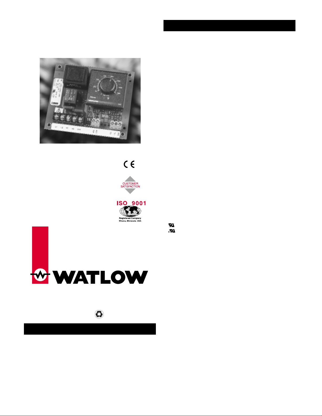
Series 147
User’s Manual
Temperature Limit
Watlow Controls
1241 Bundy Boulevard, P.O. Box 5580, Winona, Minnesota USA 55987-5580
Phone: 507/454-5300, Fax: 507/452-4507, Internet: http://www.watlow.com
Watlow’s Series 147 is an open-board temperature limit
with a thermocouple or RTD sensor input.
The Series 147 is designed to meet the needs of a wide
range of temperature limit applications. Installation and
setup are simple and easy, using basic hand tools. Factory
selectable options include high or low limit with either
manual or automatic reset on power loss.
The Series 147 has an LED output status indication
and can be ordered with an integral or a fixed set point.
(1885)
Control Mode
• High or low limit, factory selectable
• Manual or automatic reset on power loss, factory selectable
• Latching alarm with manual reset on overtemperature
• Customer-supplied reset switch
Operator Interface
• LED indication of output status
• Dial scale calibrated to compensate for sensor
non-linearities
• Integral set point
• Dual temperature scale (°F and °C)
• Fixed set point
• Manufactured to specified value
Input
• Thermocouple or platinum RTD available
• Thermocouple with automatic cold junction compensation
• Thermocouple may be isolated or grounded
• Thermocouple and RTD break protection de-energizes output
• 2- or 3-wire RTD input, 100Ω, 500Ω, or 1000Ω @ 0°C calibrated for
0.003850Ω/Ω °C curve, factory selectable
Output
• Electromechanical relay, 8A, Form C, SPDT: 8A @ 240VÅ resistive,
8A @ 28VÎ (dc) resistive, 275VApilot duty rated
Accuracy
Adjustable Set Point
• Calibration accuracy: ±1% of span, at 77°F ±5°F (25°C ± 3°C)
ambient and rated line voltage ± 1%
• Set point accuracy: ±3% of dial scale
• Accuracy span: 1000°F (540°C) minimum
Fixed Set Point
• Calibration accuracy: ±10°F/±6°C of setting, at 77°F ±5°F (25°C
±3°C) ambient and rated line voltage ±1%
Agency Approvals
• CE: EN61010 - Safety
EN61326 - Industrial Immunity, Class B Emissions
Installation Category 2, Pollution Degree 2
• 873 Recognized, File #E43684
• Recognized to C22.2 No. 24, File #E43684
• Approved for use in commercial cooking applications
• FM Class 3545
Terminals
• Sensor input and remote setpot
• Screw clamp terminal: 12-26 gauge wire
• Power input and control output
• #6 screws on barrier strip
Power
• 120V~, +10%/-15%, 50/60 Hz
• 230V~ to 240~, +10%/-15%, 50/60 Hz
• 10VAmaximum power
Operating Environment
• 32 to 131°F (0 to 55°C)
• 0 to 90% RH, non-condensing
• Storage temperature: -4 to 185°F (-20 to 85°C)
Dimensions
• Width: 4.5 in (114 mm)
• Length: 4.0 in (102 mm)
• Depth: 1.5 in (38 mm)
Weight
• 0.7 lb (0.3kg)
UL®is a registered trademark of Underwriter’s Laboratories, Inc.
Note: Specifications subject to change without notice.
Specifications
General Description
$5.00 Made in the U.S.A.
Printed on Recycled Paper
10% Postconsumer Waste
0600-0004-0011 Rev E
August 2000
Supersedes: 0600-0004-0011 Rev D
TOT AL
3 Y ear Warranty
Page 2
2 ■ Watlow Series 147 User’s Manual
(1886) 147 _ - _ _ _ _ - _ 0 0 0
Output Type
E = Electromechanical relay, 8A,
Form C
Line Voltage
1 = 120V~
2 = 230V~ to 240V~
Input and Range
Type J
601 = 32 to 600°F (0 to 315°C)
602 = 32 to 1382°F (0 to 750°C)
609 = 50 to 150°F (10 to 66°C)
614 = Fixed at 750°F (399°C)
615 = Fixed at 600°F (315°C)
Type K
603 = 32 to 2282°F (0 to 1250°C)
611 = 32 to 1112°F (0 to 600°C)
612 = 32 to 482°F (0 to 250°C)
613 = 0 to 2500°F (-17 to 1371°C)
Type T
604 = 150 to 662°F (66 to 350°C)
605 = -328 to 150°F (-200 to 66°C)
610 = -125 to 425°F (-87 to 218°C)
Type R
608 = 32 to 2732°F (0 to 1500°C)
Type S
607 = 32 to 2732°F (0 to 1500°C)
RTD (100Ω)
101 = -100 to 1112°F ( -73 to 600°C)
103 = 32 to 482°F (0 to 250°C)
Limit Mode
1 = High limit with manual reset on power loss
2 = Low limit with manual reset on power loss
3 = High limit with automatic reset on power loss
4 = Low limit with automatic reset on power loss
NOTE: Electromechanical relays are warranted for 100,000
closures only. Solid state switching devices recommended for applications
requiring extended service life.
NOTE: Conformal coated product is available; consult factory.
NOTE: This output should be used with inductive loads.
NOTE: User documentation may be available in French, German, Spanish,
Italian, and Dutch, as well as English. Check Watlow’s website (www.watlow.com/) for availability. Specify language at time of order.
The Series 147 is warranted to be free of defects in
material and workmanship for 36 months after delivery to
the first purchaser for use, providing that the unit has not
been misapplied. Since Watlow has no control over its use
or misuse, we cannot guarantee against failure. Watlow’s
obligations hereunder, at Watlow’s option, are limited to
replacement or refund of purchase price of a unit which
upon examination proves to be defective within the
warranty period. This warranty does not apply to damage
resulting from transportation, alteration, misuse or abuse.
• Call or fax Customer Service for a Return Material
Authorization (RMA) number before returning a product.
• Put the RMA number on the shipping label, and also a
description of the problem.
• A 20% of net price restocking charge applies to all
standard units returned to stock.
Contact
• Phone: +1 (507) 454-5300
• Fax: +1 (507) 452-4507
If you encounter a problem with your Watlow
controller, verify that your wiring is correct for your specific
model number. If the problem persists, an Application
Engineer can discuss your application with you.
Before calling, please have the complete model number
and user’s manual available. You can get technical support
by dialing +1 (507) 494-5656, 7 a.m. to 7 p.m. Central
Standard Time.
The Series 147 User’s Manual is copyrighted by
Watlow Winona, Inc., © August 2000, with all rights
reserved. (1884)
Technical Support
Returns
WarrantyOrdering Information
Connect according to input wiring directions, page 3.
Remove power to the controller and the controller from
the system. Apply power to the system with the
controller removed. If the load turns off, return the
controller to the factory. If the load remains on, there
are other problems in the system that must be
resolved. Consult the factory.
The polarity is reversed on the
thermocouple.
A faulty unit.
The load will not turn off.
Repair or replace.
Check the fuses, circuit breakers, load and wiring.
Check the ac input connections. If not present,
connect per Power Wiring, page 2.
An open sensor
The load circuit is open.
The ac input is not connected or
is connected improperly.
The load will not turn on.
ActionProbable CauseProblem
Troubleshooting
Page 3
4 ■ Watlow Series 147 User’s Manual
Use the following procedure to mount and install the
Watlow Series 147 temperature limit control.
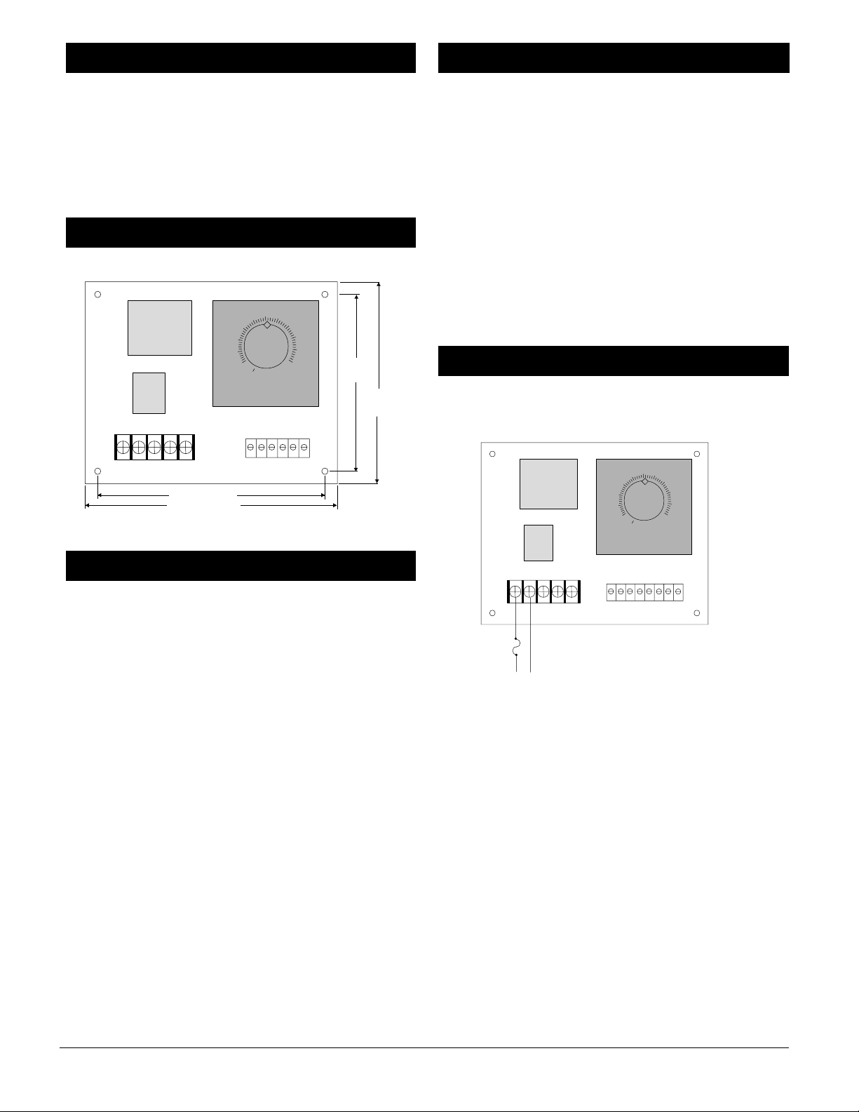
1. Locate and drill four 0.156 in (4 mm) holes in the desired
panel location. See Figure 2 for hole locations.
2. Mount the Series 147 using four #6 screws.
3. Connect the sensor, load, and power as illustrated in the
wiring diagrams on pages 2 and 3.
Figure 4a — Series 147 dimensions.
• Use the correct sensor type per the model number on the
unit sticker.
• Use the proper thermocouple or RTD polarity.
• Insulate the thermocouple mounting from the mounting
surface to prevent heat migration input errors.
• Thermocouple leads should be twisted pair wire and
routed separately from any other lines.
• In electrically noisy environments (heavy switching of
contactor, motors, solenoids, etc.) use shielded thermocouple lead wire with the shield connected at the sensor
end only.
• All wiring and fusing must conform to the National
Electric Code (NEC) NFPA70 and any other locally
applicable codes.
• Fuse the independent load voltage on the L1 (hot) side
and connect it to the common (COM) side of the relay.
• Long lead lengths create electrical resistance. When using
a two-wire RTD, there will be an additional input error
for every 1Ω of lead length resistance. That resistance
when added to the resistance of the RTD element, can
result in erroneous input to the temperature limit. To
overcome this problem, use a three- wire RTD sensor,
which compensates for lead length resistance. When
extension wire is used for a three-wire RTD, all three
extension wires must have the same electrical resistance
(i.e. same gauge, copper stranded).
Note, caution and warning symbols appear throughout this
book to draw your attention to important operational and
safety information.
A “NOTE” marks a short message to alert you to an
important detail.
A “CAUTION” safety alert appears with information that is
important for protecting your equipment and performance.
A “WARNING” safety alert appears with information that is
important for protecting you, others and equipment from
damage. Pay very close attention to all warnings that apply
to your application.
The ç symbol (an exclamation point in a triangle) precedes
a general CAUTION or WARNING statement.
The Ó symbol (a lightning bolt in a lightning bolt in a
triangle) precedes an electric shock hazard CAUTION or
WARNING safety statement.
120VÅ 147 _ - 1 _ _ _ - 0000
230VÅ 147 _ - 2 _ _ _ - 0000
NOTE: The line voltage is specified by your model number.
Figure 4b — Power wiring.
ç
WARNING: To avoid potential electric shock, use National Electrical Code
safety practices when wiring and connecting this unit to a power source and
to electrical sensors or peripheral devices. Failure to do so could result in
injury and death.
All wiring and fusing must conform to the National Electric Code and to
any locally applicable codes. Failure to comply with these recommendations
could result in damage to equipment and property, and injury to personnel.
ç
CAUTION: The Series 147 temperature limit should be mounted in an inconspicuous location to discourage unauthorized changes to the set point. Only
approved and appropriate personnel should have the authority to change the
set point on the limit switch. Failure to comply with these recommendations
could result in damage to equipment and property, and injury to personnel.
ç
CAUTION: Applying incorrect voltage may result in irreversible damage to
the controller.
Power Wiring
Safety Information
Wiring Guidelines
Dimensions
Installation
250
300
200
150
100
50
00
4.0 in (102 mm)
4.5 in (114 mm)
4.500"
350
400
450
500
3.5 in
(89 mm)
4.0 in
(102 mm)
250
300
200
150
100
50
00
350
400
450
500
Fuse
L2
L1
Recommended fuse size: 1A
Page 4
1 ■ Watlow Series 147 User’s Manual
Declaration of Conformity
Series 147
WATLOW WINONA
1241 Bundy Boulevard
Winona, Minnesota 55987 USA
Declares that the following product:
Designation: Series 147
Model Number(s): 147E - (1 or 2) (100-999) - (1, 2,3, or 4) (0 or 2) (any 2 letters
Classification: Installation Category II, Polution Degree II
Rated Voltage: 120 or 240VÅ
Rated Frequency: 50/60 Hz
Rated Power Consumption: 10VA maximum
Meets the essential requirements of the following European Union Directive(s) using the relevant
section(s) of the normalized standards and related documents shown:
or numbers)
89/336/EEC Electromagnetic Compatibility Directive
EN 61326: 1997 Electrical equipment for measurement, control and laboratory use -
EN 61000-3-2: 1995 Limits for harmonic current
EN 61000-3-3: 1995 Limitations of voltage fluctuatuions and flicker
EN 61000-4-2: 1995 Electrostatic discharge
EN 61000-4-3: 1997 Radiated immunity
EN 61000-4-4: 1995 Electrical fast transients
EN 61000-4-5: 1995 Surge immunity
EN 61000-4-6: 1994 Conducted immunity
EN 61000-4-11: 1994 Voltage dips, short interruptions and
ENV 50204: 1995 Cellular phone
EMC requirements (Emissions Class B)
voltage variations immunity
73/23/EEC Low-Voltage Directive
EN 61010-1: 1993 Safety requirements for electrical equipment for measurement,
Déclare que le produit suivant :
Désignation : Série 147
Numéro(s) de modèle(s) : 147E - (1 ou 2) (100-999) - (1, 2, 3 ou 4) (0 ou 2) (deux lettres
Classification : Installation catégorie II, degré de pollution II
Tension nominale : 120 ou 240VÅ
Fréquence nominale : 50/60 Hz
Consommation
d’alimentation nominale : 10 volt-ampères maximum
Conforme aux exigences de la (ou des) directive(s) suivante(s) de l’Union Européenne figurant
aux sections correspondantes des normes et documents associés ci-dessous :
control, and laboratory use,
Part 1: General requirements
ou chiffres quelconques)
89/336/EEC Directive de compatibilité électromagnétique
EN 61326: 1995 Appareillage électrique pour la mesure, la commande et l’usage de
EN 61000-3-2 : 1995 Limites d’émission de courant harmonique
EN 61000-3-3 : 1995 Limites de fluctuation de tension
EN 61000-4-2 : 1995 Décharge électrostatique
EN 61000-4-3: 1997 Insensibilité à l’énergie rayonnée
EN 61000-4-4 : 1995 Courants électriques transitoires rapides
EN 61000-4-5 : 1995 Insensibilité aux surtensions
EN 61000-4-6: 1996 Insensibilité à l’énergie par conduction
EN 61000-4-11 : 1994 Insensibilité aux chutes subites, aux courtes interruptions et aux
ENV 50204 : 1995 Téléphone cellulaire
laboratoire –— Prescriptions relatives à la Compatilité Electro
Magnétique (Émissions classe B)
variations de tension
73/23/EEC Directive liée aux basses tensions
EN 61010-1 : 1993 Exigences de sécurité pour le matériel électrique de mesure, de
commande et de laboratoire,
Partie 1 : Exigences générales
English
Français
Erklärt, daß das folgende Produkt:
Beschreibung: Serie 147
Modellnummer(n): 147E - (1 oder 2) (100-999) - (1, 2, 3 oder 4) (0 oder 2) (2
Klassifikation: Installationskategorie II, Emissionsgrad II
Nennspannung: 120 oder 240VÅ
Nennfrequenz: 50/60 Hz
Nominaler Stromverbrauch: Maximaler 10VA
Erfüllt die wichtigsten Normen der folgenden Anweisung(en) der Europäischen Union unter
Verwendung des wichtigsten Abschnitts bzw. der wichtigsten Abschnitte der normalisierten
Spezifikationen und der untenstehenden einschlägigen Dokumente:
beliebige Buchstaben oder Ziffern)
Deutsch
89/336/EEC Elektromagnetische Übereinstimmungsanweisung
EN 61326: 1997 Elektrogeräte zur Messung, Regelung und zum Laboreinsatz
EN 61000-3-2: 1995 Grenzen der Oberwellenstromemissionen
EN 61000-3-3: 1995 Grenzen der Spannungsschwankungen
EN 61000-4-2: 1995 Elektrostatische Entladung
EN 61000-4-3: 1997 Strahlungsimmunität
EN 61000-4-4: 1995 Elektrische schnelle Stöße
EN 61000-4-5: 1995 Spannungsstoßimmunität
EN 61000-4-6: 1994 Störimmunität
EN 61000-4-11: 1994 Immunität gegen Spannungsgefälle, kurze Unterbrechungen und
ENV 50204: 1995 Mobiltelefon
EMC-Richtlinien (Emissions Klasse B)
Spannungsabweichungen
73/23/EEC Niederspannungsrichtlinie zu entsprechen
EN 61010-1: 1993 Sicherheitsrichtlinien für Elektrogeräte zur Messung, zur
Declara que el producto siguiente:
Designación: Serie 147
Números de modelo: 147E - (1 ó 2) (100-999) - (1, 2, 3 ó 4) (0 ó 2) (Cualquier
Clasificación: Categoría de instalación II, grado de contaminación ambiental
Tensión nominal: 120 ó 240VÅ
Frecuencia nominal: 50/60 Hz
Consumo nominal de energía: 10 VA máximo
Cumple con los requisitos esenciales de las siguientes Directivas de la Unión Europea, usando
las secciones pertinentes de las reglas normalizadas y los documentos relacionados que se
muestran:
Steuerung und im Labor,
Teil 1: Allgemeine Richtlinien
combinación de dos letras)
II
Español
89/336/EEC - Directiva de Compatibilidad Electromagnética
EN 61326: 1997 Equipo elétrico para medición control y uso en laboratorios -
EN 61000-3-2 1995 Límites para emisiones de corriente armónica
EN 61000-3-3 1995 Limitaciones de fluctuaciones del voltaje
EN 61000-4-2: 1995 Descarga electrostática
EN 61000-4-3: 1997 Inmunidad radiada
EN 61000-4-4: 1995 Perturbaciones transitorias eléctricas rápidas
EN 61000-4-5: 1995 Sobretensión
EN 61000-4-6: 1994 Inmunidad conducida
EN 61000-4-11: 1994 Caídas de tensión, interrupciones breves y variaciones de tensión
ENV 50204: 1995 Teléfono portátil
Requisitos de compatibilidad electromagnética (Emisiones Clase B)
73/23/EEC Directiva de Baja Tensión
EN 61010-1: 1993 Requerimientos de seguridad para equipos eléctricos de medición,
William R. Blaisdell Winona, Minnesota, USA
Name of Authorized Representative Place of Issue
Plant Manager August 18, 2000
Title of Authorized Representative Date of Issue
________________________________________
Signature of Authorized Representative
control y uso en laboratorios,
Parte 1: Requerimientos generales
(1929)
Page 5
5 ■ Watlow Series 147 User’s Manual
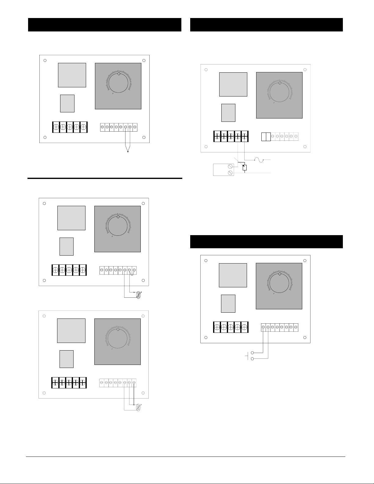
Thermocouple
Figure 5a — Thermocouple wiring.
2- and 3-wire RTD
Figure 5b — 2- and 3-wire RTD wiring.
NOTE: 2- or 3-wire RTD input, platinum 100Ω @ 0°C calibrated for
0.003850Ω/Ω°C curve.
Electromechanical Relay, Form C
8A 147E - _ _ _ _ - _ _ 00
Figure 5c — Electromechanical relay wiring.
Figure 5d — Reset wiring.
NOTE: Only the use of a momentary switch is valid for FM approval.
NOTE: Reset is customer-supplied.
Remote Reset
çNOTE: Switching inductive loads (relay coils, solenoids, etc.)
with the mechanical relay, switched dc or solid-state relay output
options requires use of an R.C. Suppressor. Watlow carries the
R.C. suppressor Quencharc brand name, which is a trademark of
ITW Paktron. Watlow Part No. 0804-0147-0000.
Output Wiring
Input Wiring
250
300
200
150
100
50
00
350
400
450
500
250
300
200
150
100
50
00
350
400
450
500
NC NO C
TC+
TC-
Customer Supplied
Quencharc
External
Device
Fuse
L1
L2
250
300
200
150
100
50
00
350
400
450
500
S3
S2
S1
2-wire RTD
250
300
200
150
100
50
00
350
400
450
500
S3
S2
S1
3-wire RTD
250
300
200
350
400
450
500
Customer-Supplied
Reset
150
100
50
00
Page 6
6 ■ Watlow Series 147 User’s Manual
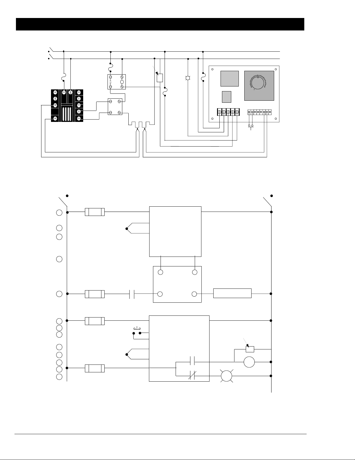
Figure 4 — System wiring examples.
120V~
System Example
L1
L2
Power
Disconnect
Switches
Fuse
11 12
Customer
Supplied
Quencharc
High Limit
Mechanical
Coil
Contactor
High-
Temperature
Light
250
300
200
350
150
100
50
400
450
500
00
3 (+)
5 (-)
93BB-1CA0-00RG
Rear View
Red
120V~
1
2
3
4
5
L1
9 +
10 -
Process Sensor
-
SSR-240-10A-DC1
OutIn
Solid-State Relay
Heater
Limit Sensor
L1 L2 NC
NO C
TC+ TC-
Reset
Series 147
Limit Controller
147E-1608-1100
+
L2
Power Disconnect SwitchPower Disconnect Switch
1
3
11 12
4 (+)
3
5 (-)
5
93BB-1CA0-00RG
Series 965
Temperature
Controller
9
6
2
10
7
3 to 32
VÎ (dc) in
(+) (-)
1 CR-1
1
8
9
SSR-240-10A-DC1
Solid-State Relay
48 to 260
V~ out
10
Heater
2
6
1
7
8
9
10
11
12
1
13
Reset
11
Switch
147E-1608-1100
(+)
Limit Controller
(-)
Com
17
Series 147
Customer
Supplied
Quencharc
NO
NC
18
R
High-Temperature Light
16
1 CR
2
2
2
 Loading...