


4RE

Wa tchGuard Video
WGD000 85 REV B1
4RE Vehicle Installation
Instructions

Vehicle Installation Instructions
About this document
This document is not meant as an exclusive blueprint for any particular vehicle, but general instructions
for a 4RE DVR installation. This instruction manual errs on the side of more information for those
persons/installers who may be new to the installation process. If there is an issue or question pertaining
to a particular vehicle make and model, please direct your questions to the WatchGuard Video
Customer Service Department at 1-800-605-MPEG (6734).
Contents
4RE Vehicle Installation Instructions ............................................................................................................ 1
About this document .................................................................................................................................... 2
Standard Parts included for a wireless installation ...................................................................................... 3
Optional parts for installation ....................................................................................................................... 3
Recommended Tools .................................................................................................................................... 4
Document Conventions: ............................................................................................................................... 4
Before installing the 4RE system in a vehicle................................................................................................ 5
Quick Overview of Installation ...................................................................................................................... 6
Starting Your Installation: ............................................................................................................................. 6
Mounting the Wireless Antenna to the Vehicle ................................................................................... 7
Mounting the Bullet Radio .......................................................................................................................... 10
Connecting the Power Cable to the Vehicle Battery .................................................................................. 11
Connecting the External Inputs Cable ......................................................................................................... 15
Ignition – White Wire .......................................................................................................................... 15
Emergency Lights – Blue with White Stripe ........................................................................................ 16
Siren – Pink and Green Wires ............................................................................................................. 17
Auxiliary – Solid Blue Wire .................................................................................................................. 18
Brake Input – Black Wire with White Stripe ....................................................................................... 19
Chassis Ground – Yellow Wire ............................................................................................................ 20
Power Over Ethernet (PoE) Adapter – Orange and Brown ................................................................. 21
PoE Ethernet Cable Connections ................................................................................................................ 21
MDC/MDT Configuration (Optional) ........................................................................................................... 22
PoE Switch ................................................................................................................................................... 22
Radar Interface Cable (Optional) – Purple/Black/Gray connector ............................................................. 23
GPS Antenna (Optional) .............................................................................................................................. 23
Display and Front Combo Camera – HDMI/HDMI mini .............................................................................. 23
Front HD camera HDMI/HDMI mini ............................................................................................................ 23
Rear analog camera HDMI/BNC and molex power..................................................................................... 23
Mounting the Remote Display Control Panel ............................................................................................. 24
Wireless Microphone .................................................................................................................................. 24
Cabin Microphone....................................................................................................................................... 25
Front HD Combination Camera ................................................................................................................... 27
Test Functions of DVR ................................................................................................................................. 30
WGD00085 REV B1 Page 2

Vehicle Installation Instructions
Qty
Part Number
Description
1
WGA00480-100
4RE, HD DVR, (2nd Generation)
1
WGA00370
4RE, Remote Display Control Panel
1
WGA00437
Camera Assembly, 4RE, HD Front, Glass mount
1
WGP01760-100
Camera, Infrared Analog, WMv.1, 2-Pin Connector
1
WGA00475-KIT
Hi-Fi Microphone Kit
Transmitter
Cradle
10 ‘Antenna Cable
Clips
1
WGA00428-001
4RE In-Car 802.11n Wireless Kit (Bullet, Antenna, PoE)
1
WGP01475
Bracket, HiFi Microphone, Universal
1
WGP01443-001-KIT
Bracket Kit, 4RE, DVR, Universal
1
WGA00420
Bracket Kit, 4RE, Display, Standard RAM 2"
1
WGP362
GPS Antenna, Magnetic Mount
1
WGD00085-KIT
Kit, 4RE DVR Installation Kit, Wireless
1
WGD00089-KIT
Kit, 4RE In-Car Video System User Guide
1
WGP01394-001
Wi-Fi Vehicle Antenna Mount, NMO, Drill 3/4" Hole,
1
WGP01506-KIT
Cable Assembly, DV-1C/4RE, Power/Input, R/A, 24'
1
WGP412
Cabin Microphone - 7'
1
WGP412-300
Cabin Microphone Extension Cable - 12'
1
WGP01832
4RE, Cable, HDMI, Port 2, Backseat Camera, 16’
1
WGP01829-004
4RE, Cable, HDMI, Front Cam, Straight, 15'
1
WGA00382
4RE, Cable, HDMI, Display/Combo Cam, Straight, 15'
Qty
Part Number
Description
1
WGA480-600
4RE, HD DVR & Mezzanine, (2nd Generation)
1
WGA00475-CHARGEKIT
Hi-Fi Microphone Desktop Charger Kit 1
1
WGP01507-004
4RE, Cable, HDMI, Display/Combo Cam, R/A, 15'
1
WGP01829-004
4RE, Cable, HDMI, Front Cam, Straight, 15'
1
WGP01688
4RE, Cable, Mezzanine, VGA to 4-Analog Cam, 7'
1
WGP01803
4RE, Cable, HDMI, Port 2, Backseat Camera, 2-Pin 16'
1
WGA00348
Camera Assembly, 4RE, HD Front/Cabin Combo, Glass Mount
1
WGA00391
4RE, Power Over Ethernet / Gigabit 4-port Switch
1
WGA00351-200
Dual Microphone Splitter, 3-Port, HiFi Mic and Trinus
1
N/A
4RE Display Bracket (varies on model of vehicle)
1
WGP01487-KIT
Bracket Kit, 4RE, DVR, Console Faceplate, 2"
Standard Parts included for a wireless installation
Optional parts for installation
WGD00085 REV B1 Page 3

Vehicle Installation Instructions
Note: Notices provide useful supplemental information that is pertinent to the task or item being
described.
Caution: Cautions describe very important information that, if ignored, could result in damage to the
system, inoperability or degradation in function, or injury to personnel.
Warning: Warnings describe critical information that should not be ignored.
Recommended Tools
Drill and bits
o ¾ inch bit for antenna mounting
o Philips bits
Coarse sandpaper 60 or 80 Grain
10-30 feet of 16-20 gauge primary wire for extending input cable connections if necessary
Wire strippers
Wire cutters
Various wrenches and sockets (one unusual open ended wrench needed is 24mm or 15/16’’)
Pliers
Utility Knife
Torx screwdrivers or bits sizes T20, T15, T10
1/16” hex screwdriver or Allen head wrench
Electrical Tape and/or heat shrink tubing
Zip ties
Document Conventions:
The following conventions are used within this document.
WGD00085 REV B1 Page 4

Vehicle Installation Instructions
Before installing the 4RE system in a vehicle
Begin by ensuring that you have received all the parts for the 4RE system. If you have any missing or
damaged parts please call WatchGuard Video Customer Service at 1-866-384-8567.
1. Ensure that the mounting brackets for the DVR, display screen, and wireless microphone bracket
are the correct types for your specific vehicle(s).
2. Gather all necessary tools for the installation.
3. Use the 4RE installation poster as a reference guide for the overview of the installation
a. If you did not receive an installation poster, you can download a copy from our website:
http://watchguardvideo.com/support/ or call 1-866-384-8567.
4. Determine if any of the cable lengths will be too short. If a cable is too short please contact
customer service for a different cable length.
5. Prepare the vehicle for installation.
a. Remove any old video equipment (if applicable)
b. Determine installation locations for the 4RE DVR, Bullet wireless radio, wireless
antenna, GPS antenna, etc.
c. Determine all wire connection points before starting the installation, i.e. vehicle battery
location, overhead input, brake input, auxiliary input, etc.
WGD00085 REV B1 Page 5
Vehicle Installation Instructions
Quick Overview of Installation
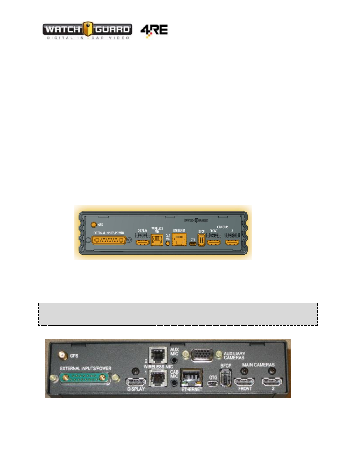
Note: If using a Mezzanine card (additional ports) the “WIRELESS MIC 2” and “AUX MIC” ports are not
used. The firmware does not activate these ports. Instead use the Dual Mic splitter.
1. Gather all tools and materials
2. Mount Radio antenna and route cable
3. Configure and mount Radio Bullet
4. Install external inputs/power cable
5. Route cables for:
a. Camera(s)
b. Wireless Microphone
c. Cabin Microphone
d. Touch display
e. Ethernet
6. Install optional cables (GPS and Radar)
7. Install optional switch for MDC/MDT application
8. Mount PoE connector
9. Mount touch display bracket
10. Mount Wireless Microphone
11. Connect and mount camera(s)
12. Connect cables to DVR
13. Insert fuse
14. Turn on DVR and test functions (Also see Quick Reference Guide to test functions)
WGD00085 REV B1 Page 6
Vehicle Installation Instructions
Caution: There are 2 different types of antenna mounts – a thru-hole antenna (NMO mount) which
requires drilling a ¾” hole in the metal of the vehicle OR a magnetic mount which does not require
drilling a hole. WatchGuard Video recommends using the NMO mount antenna if possible for better
signal strength.
Starting Your Installation:
Mounting the Wireless Antenna to the Vehicle
Find a suitable location for the antenna and a route for the antenna cable. Typically the antenna is
mounted on the roof or trunk of the vehicle. The antenna cable is then routed to where the Wireless
Radio will be placed. WatchGuard Video recommends that you configure the Wireless Radio before
mounting it into the vehicle.
Determine where you will mount the antenna. The following installation example demonstrates
mounting procedure in a Chevrolet Tahoe Police Package Vehicle. If you have a different vehicle the
installation may vary.
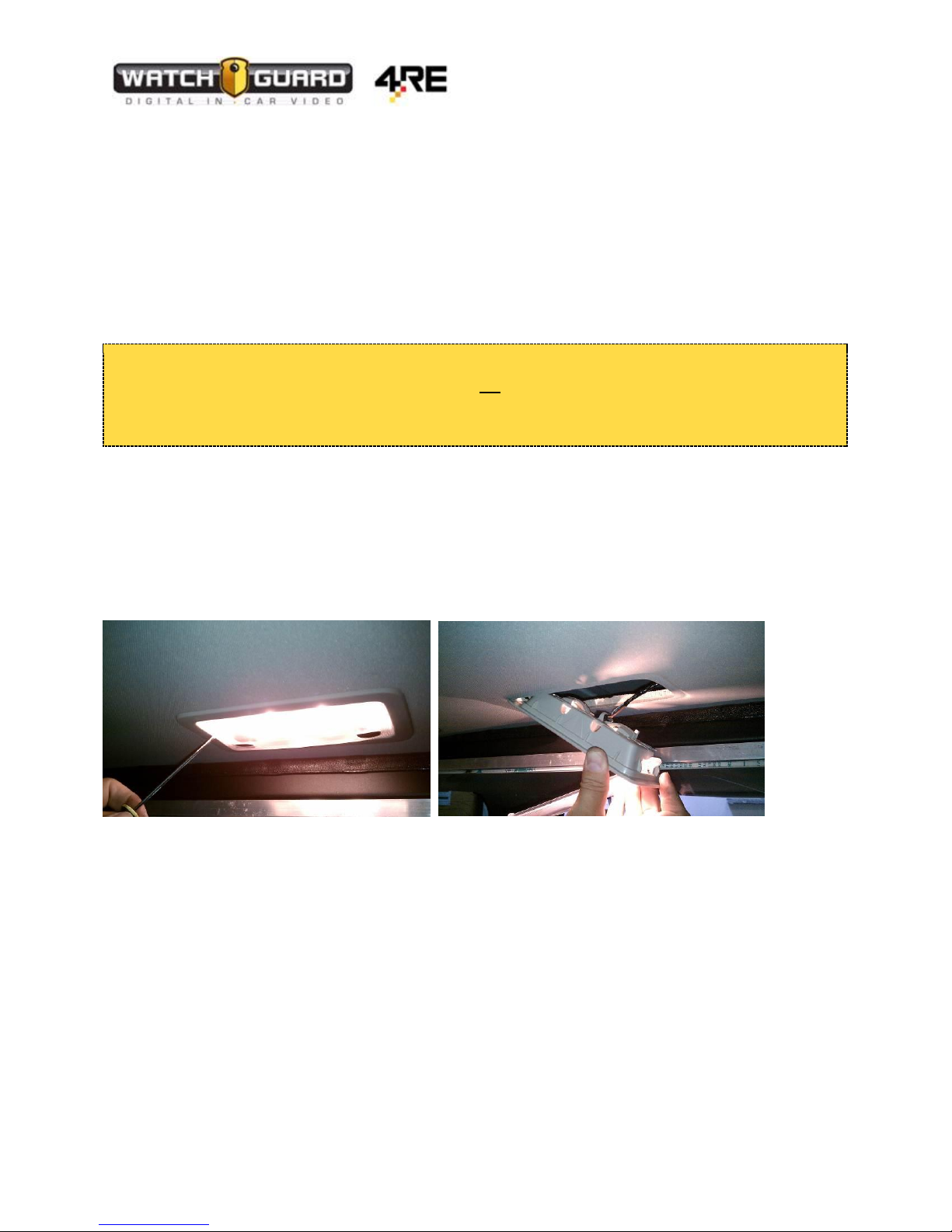
1. You can access the roof of the vehicle through a rear seat dome light or by removing the
headliner. [Figure 1 and 2]
Figure 1 Figure 2
WGD00085 REV B1 Page 7
Vehicle Installation Instructions
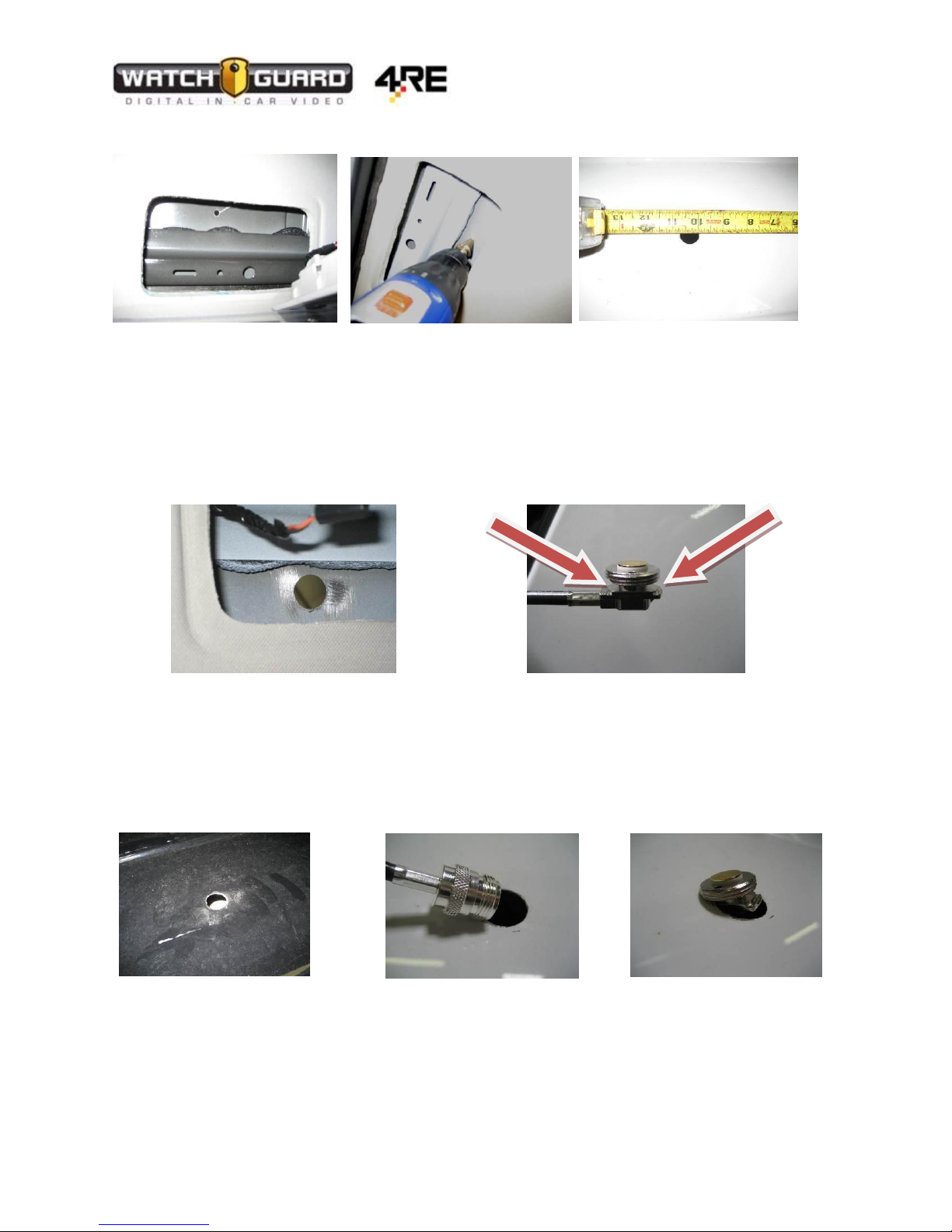
2. Drill a ¾ inch hole for the antenna cable. [Figure 5]
Figure 3 Figure 4 Figure 5
3. After the hole is made, sand the paint off the interior metal around the hole to ensure a good
ground. [Figure 6]
4. Remove the NMO exterior nut.
5. Ensure that the antenna mount ridges come in contact with the bare metal. [Figure 7]
Figure 6 Figure 7
6. Feed the antenna cable connector end first through the ¾ inch exterior hole in the roof of the
vehicle. [Figure 8 and 9]
7. Tilt the antenna mount and guide it into the hole and center the flange in the drilled hole.
[Figure 10]
Figure 8 Figure 9 Figure 10
WGD00085 REV B1 Page 8
Vehicle Installation Instructions
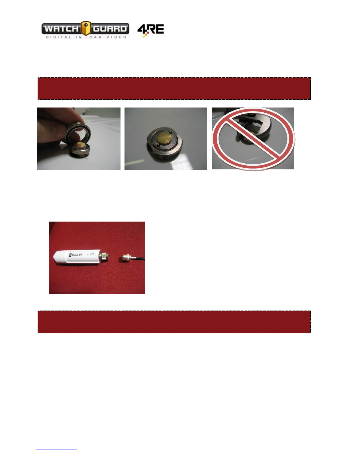
Warning: Do not use a Channel lock pliers as it could damage the NMO nut. Instead use an
open end wrench. Damaging the NMO nut could result in unreliable wireless signal.
Warning: Never plug in the PoE connector (Ethernet connection) and power up the Bullet radio
without an antenna attached as it can damage the radio.
8. Re-attach the NMO nut with the o-ring facing down to create a seal. [Figure 11]
9. Tighten the nut with a 24mm or 15/16’’ open end wrench ensuring that the mount stays
centered in the hole and that the mount does not turn and kink the cable. [Figure 12]
Figure 11 Figure 12 Figure 13
10. Route the antenna connector to where the Bullet radio will be mounted – make sure to leave
enough slack to avoid kinks.
11. Attach the antenna connector to the Bullet radio. [Figure 14]
Figure 14
WGD00085 REV B1 Page 9
Vehicle Installation Instructions
Warning: In order to configure the Bullet it must be attached to a POE power adapter and the
antenna before connecting to your computer. Make sure you attach your Ethernet cable from
your laptop to the port on the POE adapter labeled “DVR” or you may damage your laptop.
Mounting the Bullet Radio
For Instructions on how to configure the Bullet with the wireless network see the document:
Evidence Library Administrative Guide
The Bullet should be mounted in a way that the LED lights can be easily viewed for diagnostic purposes.
Common mounting locations are:
Glove compartment
On the front of the Cage
Inside the center console
There is no mounting hardware included with the Bullet radio. It is typical to use zip ties to attach the
radio to your desired location.
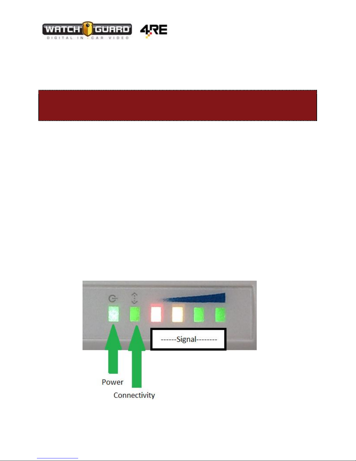
To see if the Bullet is working properly, check the LED lights on the side of the device.
1. Power LED: The power LED will be lit, if the Bullet has power.
2. Connectivity LED: This light will blink if it is communicating with the DVR
3. Signal LED’s: These 4 LED’s will light up if the Bullet is “Associated” with the Access
Point. In most cases the vehicle will not be near the Access Point during the time of
installation. Red is low signal, and each LED to the right is a better strength.
To verify the Bullet is connected properly, see Page 29.
WGD00085 REV B1 Page 10
 Loading...