

Page 1
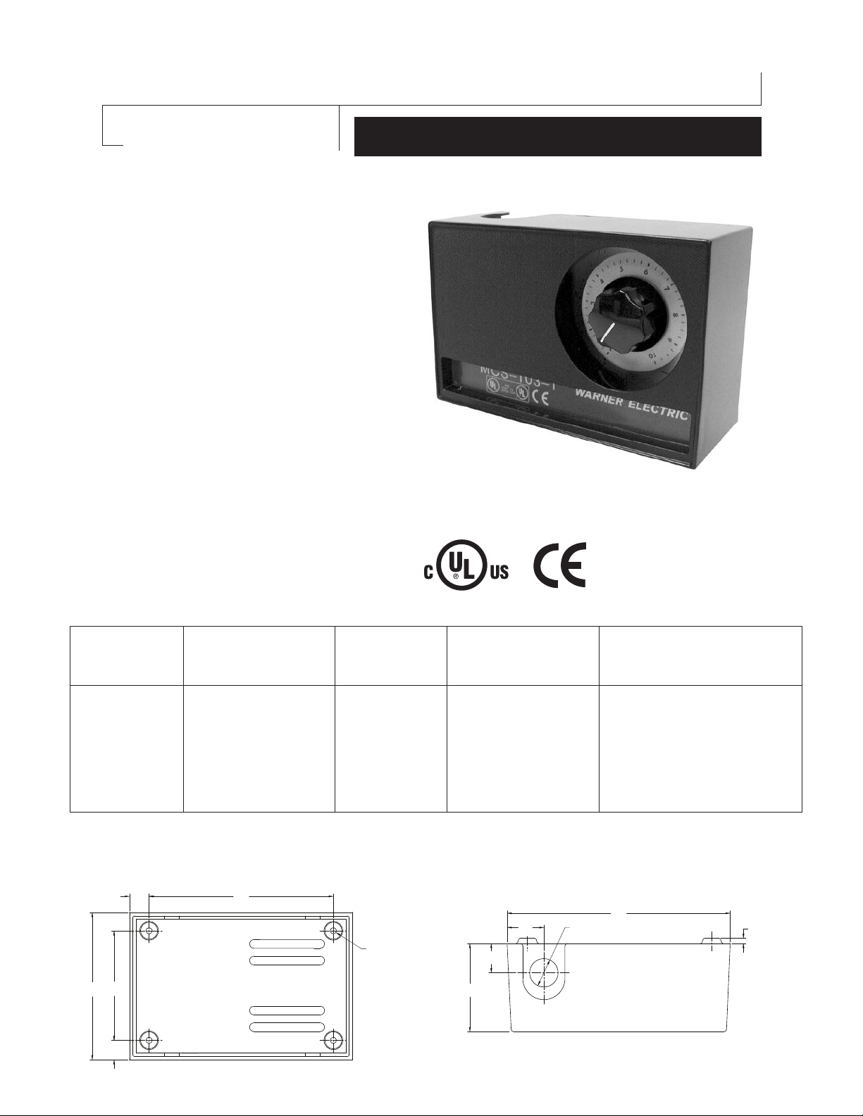
MCS-103-1 Power Supply
0.68
3.00
4.37
0.56
5.50
ÿ0.18 (4 PLCS)
(14.2)
(76.2)
(111)
(17.3)
(4.6)
(139.7)
2.75
4
ÿ0.87 BOTH SIDES
6.62
0.12
ÿ
(22)
(168.2)
(3.05)
(70)
(
1.00
(25.4)
1.06
(26.9)
with Single Torque Control
P-239-18
Installation and Operation Manual
819-0478
• Easy to install
• Compact unit mounts anywhere
• Convenient terminal strip behind an
easy-to-remove cover
• Internal arc suppression
• Operates with any Warner Electric 90V
Clutches or Brakes
The MCS-103-1 is an enclosed power supply
complete with a cover and mounting provisions.
A brake and clutch may be operated separately
with this power supply-or, two brakes or two
clutches, one unit on at a time, or clutch and ER
brake with both units on at a time. The external
wiring is connected to the terminal strip located
behind the cover.
Part Number:
6010-448-002
Specifications
AC INPUT DC OUTPUT DIMENSIONS
(Approx.)
120 VAC
50-60 HZ
* Contact ratings given will operate all Warner Electric brake and clutch units. However, switches with ratings less than those
given may be used with fractional horsepower units provided the rating is equal to or greater than the coil current.
Dimensional
1.25 amps
90 VDC for one unit
and adjustable from
0-90 VDC full wave
for second unit.
4-1/2" high
6-3/4" wide
2-3/4" deep
MOUNTING EXTERNAL SWITCHES
Mounting centers 51/2" wide, 3" high.
Knockouts for 1/2"
conduit.
Double pole, double throw
maintained contact. Minimum
contact rating:10 amp, 28 volt
DC resistive or 10 amp, 120
volt AC inductive.*
(Furnished by user)
Page 2
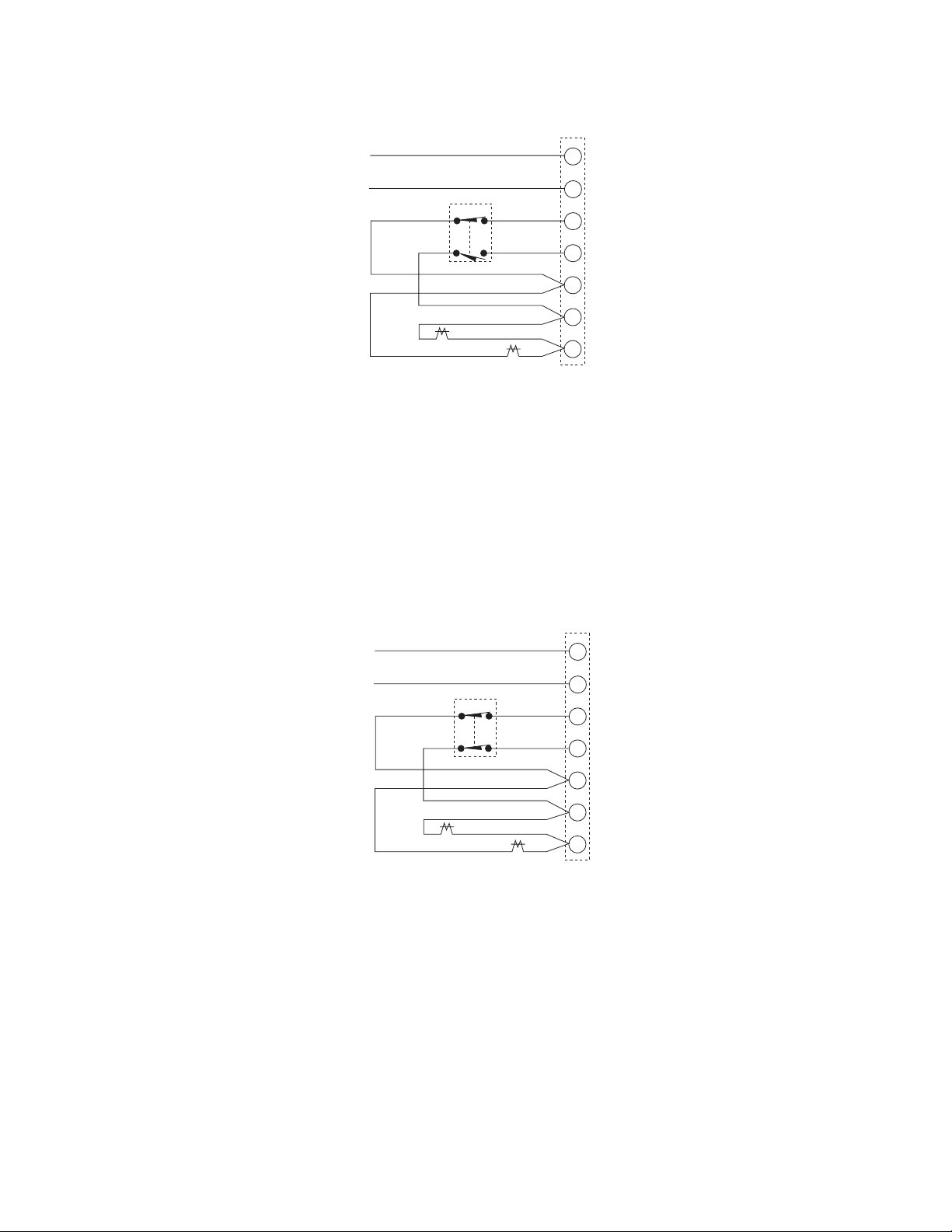
MCS-103-1 Connection Instructions for use with Standard Clutch-Brake combination
1
2
3
4
5
6
7
NEUTRAL
SWITCH
(furnished by user)
STOP
120 VAC
50-60 Hz
HOT
START
(+) 90 VOLTS
(+) ADJUSTABLE OUTPUT
(-)
90 VOLT CLUTCH
90 VOLT
BRAKE
STANDARD
1
2
3
4
5
6
7
NEUTRAL
SWITCH
(furnished by user)
STOP
120 VAC
50-60 Hz
HOT
START
(+) 90 VOLTS
(+) ADJUSTABLE OUTPUT
(-)
90 VOLT ER BRAKE
90 VOLT
CLUTCH
STANDARD
BRAKE (+)
Wiring Diagram
1. Connect the two wires fom the brake to terminals 5 and 7.
2. Connect the two wires from the clutch to terminals 6 and 7.
3. The switch (furnished by user) is connected between terminals 3 & 5 and 4 & 6 as shown in the connection diagram.
4. Connect the AC input to socket terminals 1 and 2. The "hot line" must be connected to terminal 2. This line measures
120VAC to conduit ground. The "neutral" line (color coded white or natural-gray) is grounded at the 120 VAC supply trans
former and must be connected to terminal 1. This line measures zero VAC to conduit ground. A chassis ground should be
provided as a non-current conducting ground wire (color coded green).
MCS-103-1 Connection Instructions for use with Clutch-ER Brake combination
Wiring Diagram
1. Connect the two wires from the brake to terminals 6 and 7, brake (+) to terminal 6, and brake (-) to terminal 7.
2. Connect the two wires from the clutch to terminals 6 and 7.
3. The switch (furnished by user) is connected between terminals 3 & 5 and 4 & 6 as shown in the connection diagram.
4. Connect the AC input to socket terminals 1 and 2. The "hot" line must be connected to terminal 2. This line measures
120VAC to conduit ground, The "neutral" line (color coded white or natural-gray) is grounded at the 120 VAC supply
transformer and must be connected to terminal 1. This line measures zero VAC to conduit ground. A chassis ground
should be provided as a non-current conducting ground wire (color coded green).
NOTE: For proper operation, observe polarity for connection of ER brake to power suppy terminal strip.
Warner Electric • 800-234-3369 P- 239-18 • 819-0478
2
Page 3

DECLARATION OF CONFORMITY
WE: WARNER ELECTRIC
31 Industrial Park Road
New Hartford, Ct 06057
declare under our sole responsibility that the products of the family
MCS 103-1
DECLARACION DE CONFORMIDAD
Nosotros: WARNER ELECTRIC
31 Industrial Park Road
New Hartford, CT 06057
declaramos bajo nuestra propia responsabilidad que los productos de la familia
MCS 103-1
are exclusively designed for incorporation in another machine. The operation of the
product is submitted to the conformity of the complete equipment, following the
provisions of the directive 89/392/EEC.
The conformity of the above specified products with the provisions of the Directive
72/23/EEC is supported by the full respect of the standards EN 61010-1.
If the mounting and connecting instructions of the installation manual have been
respected, this product will be conforming to the standards EN50081-1 and
EN50082-1 relating to the EMC directive 89/336/EEC.
New Hartford, CT 06057
VP and General Manager: M. T.
To avoid injury, always make certain
all power is off before attempting
to install or repair this control.
DO NOT TOUCH THE BOARD IF POWER IS APPLIED.
Mounting and Connecting Instructions
related to the EMC-directive 89/336/EEC
For Clutch and Brake Control
1. The control must be mounted in a closed metal cabinet.
2. The power connection between control and clutch/brake must be MADE
using shield cable.
3. The control connection must utilize shielded cables.
4. The shield of the cables must be grounded at both ends.
5. Power connections and control connection must be placed in separate
canals.
son diseñados exclusivamente para incorporarse en otra maquina. El
funcionamiento de este producto esta sujeto al cumplimiento de todo el equipo
usado en la maquina, con los lineamientos de la norma 89/392/EEC.
El cumplimiento de los lineamientos de la norma 72/23/EEC con los productos
mencionados anteriormente, se basa y respeta los estandares EN 61010-1.
Si las instrucciones de montaje e instalación electrica del instructivo son
respetadas, este producto cumplirá con los estandares EN50081-1 y EN50082-
1 que se relacionan con la norma 89/336/EEC.
New Hartford, CT 06057
VP and General Manager: M. T.
ADVERTENCIA:
Para evitar cualquier daño
personal, antes de intentar
instalar o reparar este control,
siempre asegurese que todas
las fuentes de poder esten apagadas.
NO TOQUE EL CIRCUITO ELECTRICO SI LA FUENTE DE PODER
ESTA ENCEDIDA.
INSTRUCCIONES DE MONTAJE Y
CONEXIONES ELECTRICAS
en relación a la norma de EMC 89/336/EEC
PARA CONTROLES DE CLUTCHES Y FRENOS
1. El control debe de instalarse adentro de una caja metalica.
2. Las conexiones electricas entre el control y el cluch/freno DEBEN hacerse
con cable blindado.
3. Las conexiones de bajo voltaje en el control deben utilizar cables blindados.
4. El blindaje de los cables debe de aterrizarse en ambos lados.
5. Las conexiones entre la fuente de poder, y las conexiones de bajo voltaje
deben de hacerse en diferentes cables.
KONFORMITÄTSERKLÄRUNG
Wir: WARNER ELECTRIC
erkälren in alleiniger Verantwortung, daß die Prdukte der Familie
ausschließlich zum Einbau in eine andere Maschine bestimmt sind. Die
Inbetriebnahme ist solange untersagt, bis die Konformität des Endproduktes mit
der Richtlinie 89/392/EWG gegeben ist.
Die Übereinstimmung des bezeichneten Produktes mit den Vorschriften der
Richtlinie 72/23/EWG wird nachgewiesen durch die Einhaltung der Normen EN
61010-1.
Sofern die Montage-Anweisungen der Bedienungsanleitung eingehalten wurden,
ist dieses Podukt knoform zu EN50081-1 und EN50082-1 und die EMV somit
gewährleistet - Richtlinie 89/3366/EWG.
New Hartford, CT 06057
VP and General Manager: M. T.
KARTE BEI EINGESCHALTETER STROMVERSORGUNG NICHT
BERÜHREN.
bezogen zu den EMW Richtlinic 89/336/EWG
FÜR STEURGERÃTE KUPPLUNGEN UND BREMSEN
1. Das Gerãt muß in einem gesclossenen metallschrank eingebaut werden.
2. Leistungsverbindungen Steuergerãte/Kupplungen - Bremsen mit abgeschim
3. Steuerdeitungen, Ein-und Ausgãnge mittels abgeschimten Kabeln
4. Abschirmung an beiden Enden des Kabels erden.
5. Leistungs-und Steuerverbindungen in separate Kabelkanãle durchziehen.
31 Industrial Park Road
New Hartford, CT 06057
WARUNG:
MONTAGE UND KABELVERBINDUNGEN
Kabel durchfubren.
durchführen.
MCS 103-1
Vor Einbau oder Wartung des
Gerätes unbedingt die
Stromversorgung unterbrechen um
Verletzungen zu vermeiden.
ANWEISUNGEN
DÉCLARATION DE CONFORMITÉ
Nous: WARNER ELECTRIC
déclarons sous notre seule responsabilité que les produits de la famille
sont uniquement destinés à l’intégration dans une machine. La mise en service
de ces produits est subséquente à l’homologation de l’ensemble de
l’équipmement, conformément à la directive 89/392/CEE.
La conformité des produits spécifiés ci-dessus avec les exigences de la directive
72/23/CEE est supportée par le respect des normes EN 61010-1.
Si les instructions de montage et de câblage du manuel sont respectées, ce
produit est conforme aux normes EN50081-1 et EN50082-1 directive
89/336/CEE relative à la CEM.
New Hartford, CT 06057, VP and General Manager: M. T.
ou intervention sur ces équipements.
NE PAS TOUCHER LE CIRCUIT ÉLECTRONIQUE, SI LA PUISSANCE
EST APPLIQUÉE.
relatives à la CEM, directive 89/336/CEE
DES CONTROLES POUR EMBRAYAGES ET FREINS
1. L’ appareil doit être monté dans une armoire métallique close.
2. Liasion de puissance entre contrôle et embrayage/frein par cãble blindé.
3. Raccordements de consigne, entrées et sorties par cãbles blindés.
4. Les blindages sont reliés à la terre aux deux extrémités du cãble.
5. Les cãbles de commande et les cãbles de puissance ne seront pas placés
dans le mëme caniveau.
31 Industrial Park Road
New Hartford, CT 06057
MCS 103-1
Afin d’éviter des blessures,
ADVERTISSEMENT:
s’assurer que toute puissance
soit coupée avant installation
INSTRUCTIONS D’INSTALLATION
ET DE CABLAGE
Page 4

Warranty
Warner Electric LLC warrants that it will repair or replace (whichever it deems advisable) any
product manufactured and sold by it which proves to be defective in material or workmanship within a
period of one (1) year from the date of original purchase for consumer, commercial or industrial use.
This warranty extends only to the original purchaser and is not transferable or assignable without
Warner Electric LLC’s prior consent.
Warranty service can be obtained in the U.S.A. by returning any defective product, transportation
charges prepaid, to the appropriate Warner Electric LLC factory. Additional warranty information may
be obtained by writing the Customer Satisfaction Department, Warner Electric LLC, 449 Gardner
Street, South Beloit, Illinois 61080, or by calling 815-389-3771.
A purchase receipt or other proof of original purchase will be required before warranty service is
rendered. If found defective under the terms of this warranty, repair or replacement will be made,
without charge, together with a refund for transportation costs. If found not to be defective, you will be
notified and, with your consent, the item will be repaired or replaced and returned to you at your
expense.
This warranty covers normal use and does not cover damage or defect which results from
alteration, accident, neglect, or improper installation, operation, or maintenance.
Some states do not allow limitation on how long an implied warranty lasts, so the above limitation may
not apply to you.
Warner Electric LLC’s obligation under this warranty is limited to the repair or replacement of the
defective product and in no event shall Warner Electric LLC be liable for consequential, indirect,
or incidental damages of any kind incurred by reason of the manufacture, sale or use of any defective
product. Warner Electric LLC neither assumes nor authorizes any other person to give any other
warranty or to assume any other obligation or liability on its behalf.
WITH RESPECT TO CONSUMER USE OF THE PRODUCT, ANY IMPLIED WARRANTIES WHICH THE
CONSUMER MAY HAVE ARE LIMITED IN DURATION TO ONE YEAR FROM THE DATE OF ORIGINAL
CONSUMER PURCHASE. WITH RESPECT TO COMMERCIAL AND INDUSTRIAL USES OF THE
PRODUCT, THE FOREGOING WARRANTY IS IN LIEU OF AND EXCLUDES ALL OTHER
WARRANTIES, WHETHER EXPRESSED OR IMPLIED BY OPERATION OF LAW OR
OTHERWISE, INCLUDING, BUT NOT LIMITED TO, ANY IMPLIED WARRANTIES OF
MERCHANTABILITY OR FITNESS.
Some states do not allow the exclusion or limitation of incidental or consequential damages, so the
above limitation or exclusion may not apply to you. This warranty gives you specific legal rights and
you may also have other rights which vary from state to state.
Changes in Dimensions and Specifications
All dimensions and specifications shown in Warner Electric catalogs are subject to change without
notice. Weights do not include weight of boxing for shipment. Certified prints will be furnished without
charge on request to Warner Electric.
Warner Electric LLC
31 Industrial Park Road
815-389-3771
www.warnerelectric.com
An Altra Industrial Motion Company
P-239-18 819-0478 06/11 Printed in USA
• Fax: 815-389-2582
• New Hartford, CT 06057
 Loading...