

Page 1
P-2067-WE
SM320gb - rev 02/09
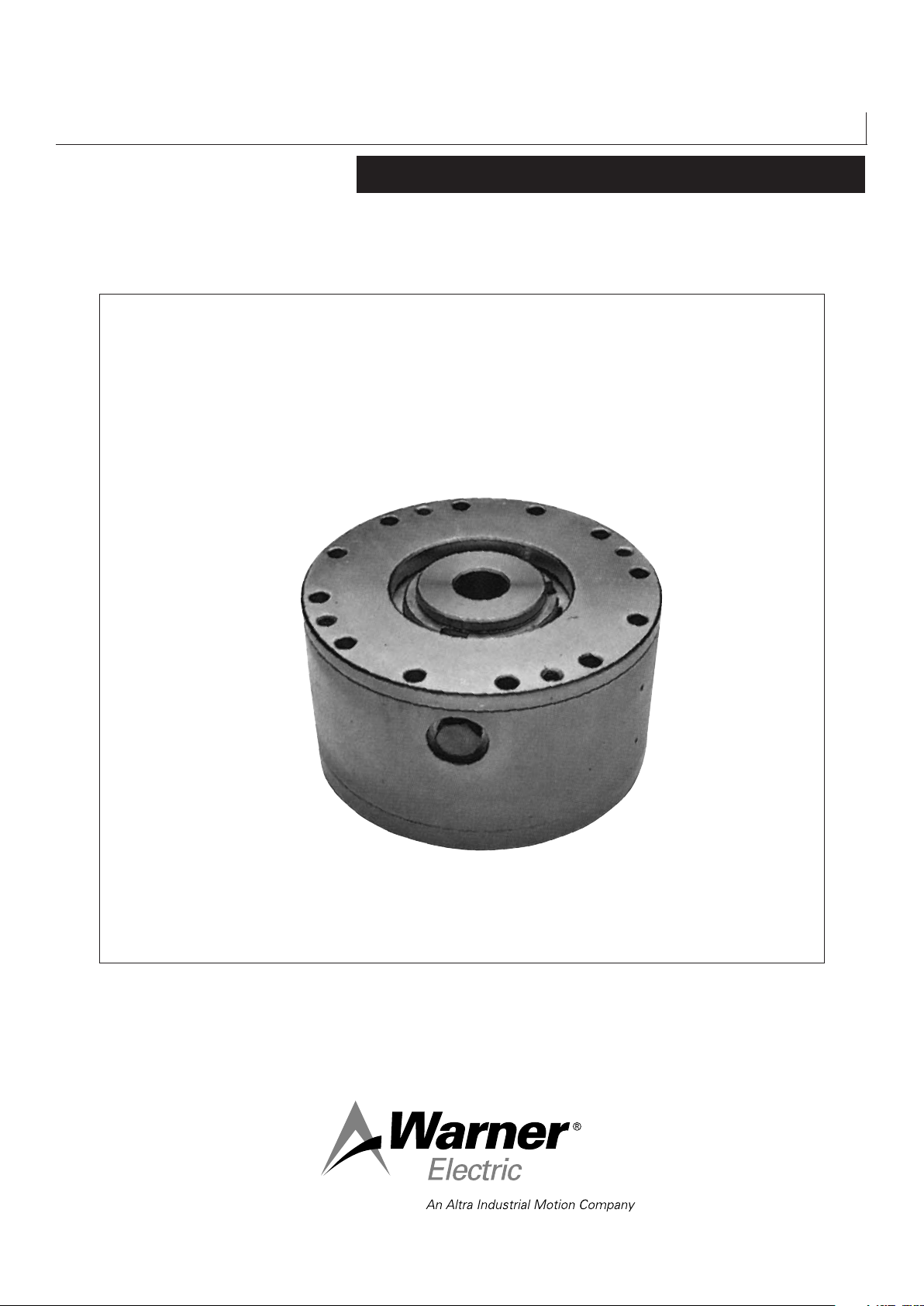
Hydraulic Multi-Disc Brake
H420
Service Manual
Page 2
We, WARNER ELECTRIC EUROPE, 7, rue Champfleur, B.P. 20095, F-49182 St Barthélemy d’Anjou Cedex
declare that the brakes made in our factories from St Barthélemy d’Anjou,
and hereafter designated : H420
are intended to be incorporated in an installation or to be assembled with other machinery with a view to constituting a machine to which
direc tive 98/37/EC.
Drawn up in St Barthélemy d’Anjou, July 2002
E. PRAT, General Managing Director
CONTENTS
1 Technical specification 2
2 Precautions and restrictions on use 2
2.1 Restrictions on use 2
2.2 Precautions in use 2
and safety measures
3 Installation 3
3.1 Transport - storage 3
3.2 Handling 3
3.3 Installation 3
3.4 Manual release 3
4 Maintenance 3
4.1 Maintenance 3
4.2 Spare parts 3
4.3 Dismantling / reassembling 3-4
5 Hydraulic connection 4
5.1 Important recommendations 4
5.2 Hydraulic oils 4
5.3 Connection diagrams 5
6 Appendix 6
7 Troubleshooting 6
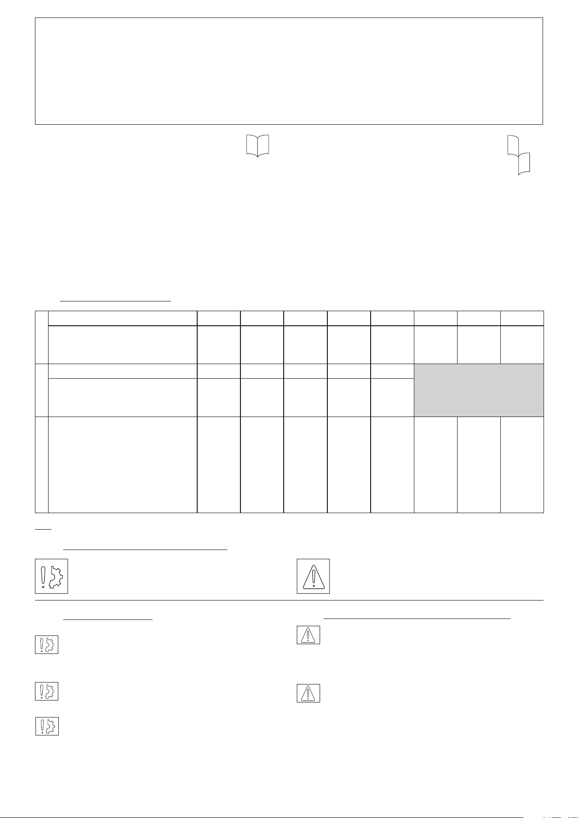
1 Technical specifications
STANDARD Size 90 150 250 550 1000 3200 6400 12800
Max speed min
P min. bar
VAR 00VAR 01
P max. bar
-1
5000
29
320
5000
24
320”
4200
21
320
3500
“23
320
2500
22
320
1700
22
350
1400
35
350
HIGH TORQUE Size 150 220 330 730 1600
Max speed min
P min. bar
P max. bar
Hydraulic connection NF E03-004 Locking screws (909) Tightening torque Nm
Releasing screw Length mm
Oil change, ling and oil level cap -
-1
5000
48
320
RP 1/8”
12 x M8
38
2 x M6
20
2 x M8
5000
36
320
RP 1/8”
12 x M8
38
3 x M6
20
3 x M8
4200
28
320
RP 1/4”
12 x M8
38
3 x M6
25
3 x M8
3500
31
320
RP 1/4”
12 x M10
75
3 x M8
30
3 x M12
2500
36
320
RP 1/4”
12 x M12
130
3 x M8
30
3 x M12
RP 3/8”
12 x M16
325
3 x M10
35
3 x M14
RP 1/2”
12 x M20
637
3 x M16
40
3 x M20
(936, 937, 939)
Weight Kg
6,0
8,2
12,0”
20,0
37,5
119
196
1100
35
350
RP 1/2”
12 x M24
700
6 x M16
80
3 x M20
360
NB: Data for catalogue equipment Table 1
2 Precautions and restrictions on use
Symbol designating an action that
might damage the apparatus
2.1 Restrictions on use
This equipment is designed for the disc stack to run
in oil. Dry operation is possible, but only in a
static application.
2.2 Precautions in use and safety measures
During maintenance, ensure that the mechanism
Symbol designating an action that
might be dangerous to human safety
to be braked by the equipment is at rest and
that there is no risk of accidental start-up.
All intervention have to be made by qualified
Exceeding the maximum rotation speed stated in the
catalogue invalidates the warranty.
This equipment is designed to run with the shaft
horizontal.
personnel, owning this manual.
Any modification made to the brake without
the express authorisation of a representative of
Warner Electric, in the same way than any use
out of the contrac tual specifications accepted by
“Warner Electric”, will result in the warranty being
invalidated and Warner Electric will no longer be
liable in any way with regard to conformity.
2 Warner Electric Europe • +33 (0)2 41 21 24 24 P-2067-WE • 2/13
Page 3

3 Installation
In the case of operation in oil only:
3.1 Transport / storage
The brakes are supplied in packaging
guaranteeing a preservation period of 6 months
with land or air transport, or after transport by
ship to neighbouring continents (with out crossing
the tropics).
3.2 Handling
The brake is supplied assembled, the hub (515)
pre centred in place.
Be careful not to release the disk stack before
assembly.
Avoid any impacts on the equipment so as not to
alter their performance.
3.3 Installation
The hub (515) is normally supplied to H7
tolerances for bore and P9 for the width of the
keyway (in accordance with NF E 22-175 / DIN
6885 / BS 4235 / ISO R773).
• Locate the hub on the shaft (after adjusting the
key) and fix it axially
NB: For VAR00 sizes 90 / 150 / 250 and VAR01
sizes 150 / 220 / 330, the hub (515) should be
fitted in the right direction: the largest diameter
towards the shoulder of the shaft.
• Slide the equipment into position in the
centring provided, having first directed the
supply to the top position of the vertical axis,
while presenting the hollows of the steel or
sintered inner disc (308) or (309) opposite to
the hub teeth (515)
• Pivot the assembly until the fixing holes
coincide with the bolt ways in the brake.
• Fix the brake with the bolts provided for the
purpose
Do not forget to tighten the locking screws (909)
to the torque (table 1) and to secure them with a
Loctite 243 type or equivalent product.
• Connect the hydraulics (see table 1)
• Remove the filling cap (937) and oil level cap
(939) (the lowest of the plugs located at the
back). Pour in the oil (see chap. 5 for the
choice) up to the level required. Replace the
caps
3.4 Manual Release
Brakes in the H420 range can be released
manually so as to put the brake out of operation,
in the event of a fault in the hydraulic circuit
or for maintenance. To do this, the caps (939)
must be removed so as to access the tapped
holes provided in the piston (402). Fit a set of
bolts (given in table 1) and screw them right in to
compress the springs.
4 Maintenance
4.1 Maintenance
There is practically no wear on the discs of units
in the H420 range if the running conditions are
complied with (operation in oil, oil temperature,
rotation speed, etc.). Disc wear is automatically
compensated for, up to the wear limit, by the
movement of the piston. It is however necessary
to:
• Regularly check the piston seal (402) and in the
event of a leak or after 5 years use, change the
seals (703, 704) and back-up rings (722, 723)
In the case of operation in oil only:
• Change the oil after 40 h running from first use,
then every year of normal running.
4.2 Spare parts
For all orders of spare parts, state the size of the
equipment with its code number, the part number
(see Appendix) and the quantity required.
4.3 Dismantling / reassembling
During the maintenance period, ensure that the
mechanism to be braked by the equipment is at
rest and that there is no risk of accidental start-
up. Also ensure that the hydraulic supply is shut
off.
Warner Electric Europe • +33 (0)2 41 21 24 24 P-2067-WE • 2/13 3
Page 4

After removing the equipment from the shaft,
proceed as follows:
• Where the equipment is running in oil, drain it
• Remove the manual braking screws and
replace the caps (939)
• Refit the brake as described in paragraph 3.3
• Manually release the equipment’s brake
• Remove the pre-assembly screws and remove
the closing plate (359) with the piston (402) and
springs (740)
Changing the disk stack:
• Remove the flange (357)
• Remove the worn disk stack
• Put the new set of disks in place, starting with
an outer disc (303 or 304), followed by an inner
disc (308 or 309) and ending with an outer disc
• Do not forget to seal fhe faces of the flange
(357) and of the closing plate (359), with an an
anareobic material (Loctite 549, for exemple)
Changing the seals:
• Do not forget to replace the back-up rings
(722)and (723) with the seals (703) and (704)
situated on the pressure chamber side
• Before reassembling, lightly oil slip surfaces
with control oil
• Reassemble the closing plate (359) with the
piston (402)
• Equipment of sizes 3200 to 12800 contain
seals (706) fitted on the flange (357) and
closing plate (359): check their condition and
change if necessary
Do not forget to tighten the fixing bolts to torque
(see Table 1) and to secure them with a Loctite
243 or equivalent type product.
5.1 Hydraulic connection 5-1Important
recommendations
Ensure compliance with the operating
pressure so as to get the equipment’s nominal
performance.
Ensure that the maximum pressure is not
exceeded (see table 1).
We recommend filtration of the control of about
10 microns so as to guarantee trouble-free run
ning and a correct life of the hydraulic
components.
The disc lubricating oil should not exceed 80°C in
operation.
5.2 Hydraulic Oils
The types of oil to use for lubricating the discs
should ful fil the following criteria:
• Good resistance to oxidation
• No additives modifying friction
• No additives that could corrode the bronze
friction surfaces (1a or 1b NF M07-015)
• Compatible with the materials used for the
hydraulic seals
Do not damage the seals during reassembly.
• Replace the fixing bolts in the closing plate
(359)
• Use the hub (515) to align the teeth of the
interior disc stack.
• High viscosity rating (>80)
The oils listed below meet these characteristics,
this list is not exhaustive and can be added to
by other oils. The viscosity of the oil to choose
varies according to temperature and running
speed (measured on the ext. dia. of the cylinder).
Mineraloil ATF
Viscosity
Running Speed
BP
ESSO
MOBIL
SHELL
ELF
4 Warner Electric Europe • +33 (0)2 41 21 24 24 P-2067-WE • 2/13
ISO VG 22
> 12 m/s
Nuto H22
DTE 22
Tellus 22
ISO VG 32
> 12 m/s
Energol HLP-D32
Nuto h 32
DTE Oil Light
Tellus 32
Polytelis 32
ISO VG 46
> 12 m/s > 12 m/s
Energol HLP-D46
Nuto H 46
Autran MBX
AT Dexron II
DTE Oil Medium
Tellus 46
Donax TM Elfmatic
Polytelis 46
ATF 220
G2”
Page 5

Figure 1
Figure 1: Basic circuit for multidisc brake with hydraulic release
a: Reservoir
g
f
b: Pump
c: Filter
d
e
d: Pressure gauge
e: Pressure limiter
c
f: Distributor
g: Brake
The brake is lubricated by splashed non renewed oil.
M
b
Figure 2
a
Figure 2: Hydraulic release, multidisc brake assembly in
open circuit with hydraulic motor
a: Reservoir
f
g
d
h
b: Pump
c: Filter
d: Pressure gauge
e: Pressure limiter
f: Distributor
c
e
g: Brake
h: Flow restricter with non-return valve
The distributor in central position causes the oil to return to the
reservoir and the brake to close. Going to one of the two other
M
b
a
positions causes the brake to open and the hydraulic motor to
rotate, in one or other direction, according to the position of the
slider.
p
n
g
f
Figure 3
d
e
Figure 3: Hydraulic release, multidisc brake assembly in
closed circuit with hydraulic motor
a: Reservoir g: Brake
b: Pump h: Pump
c: Filter n: Distributor
d: Pressure gauge o: Calibrated non-return valve
e: Pressure limiter p: Hydraulic motor
M
o
h
c
f: Distributor
The distributor for the hydraulic motor and brake are controlled
simultaneously causing the brake to release and the motor to rotate.
M
b
Warner Electric Europe • +33 (0)2 41 21 24 24 P-2067-WE • 2/13 5
a
Page 6

6 Appendix
Size 90 to 12800 : VAR00
Size 150 to 1600 : VAR01
308 or 309
723
357
515
303
or
304
7 Troubleshooting
7229 09
09
401
740
402
939
705
359704703936 or 937
NO. Description
303
304
308
309
357
359
401
402
515
703
704
705
722
723
740
909
936
937
939
Steel outer disc
Stintered outer disc
Steel inner disc
Stintered inner disc
Flange
Closing plate
Cylinder
Piston
Hub
Cylinder Quad ring seal
Piston Quad ring seal
Flat ring
Back up ring piston
Back up ring cylinder
Spring
Locking screw
oil chang cap
Filling cap
Oil level cap
Troubleshooting
Problem Possible Causes Remedies
The brake does
not brake
The brake does
not release
• Brake under hydraulic pressure
• Manual release screw in position
• Disc worn or damaged
• Piston seals worn or damaged
• No pressure
• No sufcient pressure
• Check the circuit control
• Remove the manual release screws
• Change the disc
• Change the seals
• Check the hydraulic circuit and control
• Increase the pressure
6 Warner Electric Europe • +33 (0)2 41 21 24 24 P-2067-WE • 2/13
Page 7

NOTES
Warner Electric Europe • +33 (0)2 41 21 24 24 P-2067-WE • 2/13 7
Page 8

Warranty
Warner Electric LLC warrants that it will repair or replace (whichever it deems advisable) any product manufactured and
sold by it which proves to be defective in material or workmanship within a period of one (1) year from the date of original
purchase for consumer, commercial or industrial use.
This warranty extends only to the original purchaser and is not transferable or assignable without Warner Electric LLC’s
prior consent.
Warranty service can be obtained in the U.S.A. by returning any defective product, transportation charges prepaid, to
the appropriate Warner Electric LLC factory. Additional warranty information may be obtained by writing the Customer
Satisfaction Department, Warner Electric LLC, 449 Gardner Street, South Beloit, Illinois 61080, or by calling 815-389-
3771.
A purchase receipt or other proof of original purchase will be required before warranty service is rendered. If found
defective under the terms of this warranty, repair or replacement will be made, without charge, together with a refund for
transportation costs. If found not to be defective, you will be notified and, with your consent, the item will be repaired or
replaced and returned to you at your expense.
This warranty covers normal use and does not cover damage or defect which results from alteration, accident, neglect, or
improper installation, operation, or maintenance.
Some states do not allow limitation on how long an implied warranty lasts, so the above limitation may not apply to you.
Warner Electric LLC’s obligation under this warranty is limited to the repair or replacement of the defective product and
in no event shall Warner Electric LLC be liable for consequential, indirect, or incidental damages of any kind incurred by
reason of the manufacture, sale or use of any defective product. Warner Electric LLC neither assumes nor authorizes any
other person to give any other warranty or to assume any other obligation or liability on its behalf.
WITH RESPECT TO CONSUMER USE OF THE PRODUCT, ANY IMPLIED WARRANTIES WHICH THE CONSUMER MAY
HAVE ARE LIMITED IN DURATION TO ONE YEAR FROM THE DATE OF ORIGINAL CONSUMER PURCHASE. WITH
RESPECT TO COMMERCIAL AND INDUSTRIAL USES OF THE PRODUCT, THE FOREGOING WARRANTY IS IN LIEU
OF AND EXCLUDES ALL OTHER WARRANTIES, WHETHER EXPRESSED OR IMPLIED BY OPERATION OF LAW OR
OTHERWISE, INCLUDING, BUT NOT LIMITED TO, ANY IMPLIED WARRANTIES OF MERCHANTABILITY OR FITNESS.
Some states do not allow the exclusion or limitation of incidental or consequential damages, so the above limitation or
exclusion may not apply to you. This warranty gives you specific legal rights and you may also have other rights which
vary from state to state.
Changes in Dimensions and Specications
All dimensions and specifications shown in Warner Electric catalogs are subject to change without notice. Weights do not
include weight of boxing for shipment. Certified prints will be furnished without charge on request to Warner Electric.
Warner Electric Europe
7 rue Champfleur, B.P. 20095, St Barthelemy d’Anjou - France
+33 (0)2 41 21 24 24 • Fax: +33 (0)2 41 21 24 70
www.warnerelectric.com
Printed in USAP-2067-WE • 2/13
 Loading...