

Page 1
P-2066-WE
SM301gb - rev 02/09
Hydraulic Multidisc Clutch
H 110 VAR00
Service Manual
Page 2
We, WARNER ELECTRIC EUROPE, 7, rue Champfleur, B.P. 20095, F-49182 St Barthélémy d’Anjou
Cedex, declare that the clutches made in our factories from St Barthélémy d’Anjou,
and hereafter designated : H110 VAR 00
are designed to be incorporated into an installation or assembled with other equipment in order to form a machine that is covered by directive 98/37/EC.
St Barthélémy d’Anjou, July 2002
Eric Prat, General Managing Director
CONTENTS
1 Technical specifications 2
2 Precautions and restrictions on use 2
2.1 Restrictions on use 2
2.2 Precautions in use and safety measures 3
3 Installation 3
3.1 Transport - storage 3
3.2 Handling 3
3.3 Setting up 3
4 Maintenance 4
1 Technical specifications
Size 100 200 400 800 1600
N max. rpm
P nominal bar
P max. bar
Weight kg
Length “L±0,5” mm
Size 3200 6400 12800 25600 51200 102400
N max. tr/min
1500
P nominal bar
P max. bar
Weight kg
Length “L±0,5” mm
NB : data for catalogue equipment
3600
10
12
5,3
81
10
12
55
155
Table 1
4.1 Maintenance 4
4.2 Spare parts 4
4.3 Dismantling / Reassembling 4
5 Hydralic connection 5
5.1 Important recommendations 5
5.2 Hydraulic oils 5
5.3 Connection diagrams 6
6 Appendice 7
6.1 Diagram 7
7 Troubleshooting 7
2900
8
10
8,5
89
1300
10
12
87
170
1200
16
18
124
190
2700
8
10
11,5
96
1000
16
18
262
235
2000
10
12
22
118
900
16
18
510
290
1800
10
12
35
135
800
22
24
770
330
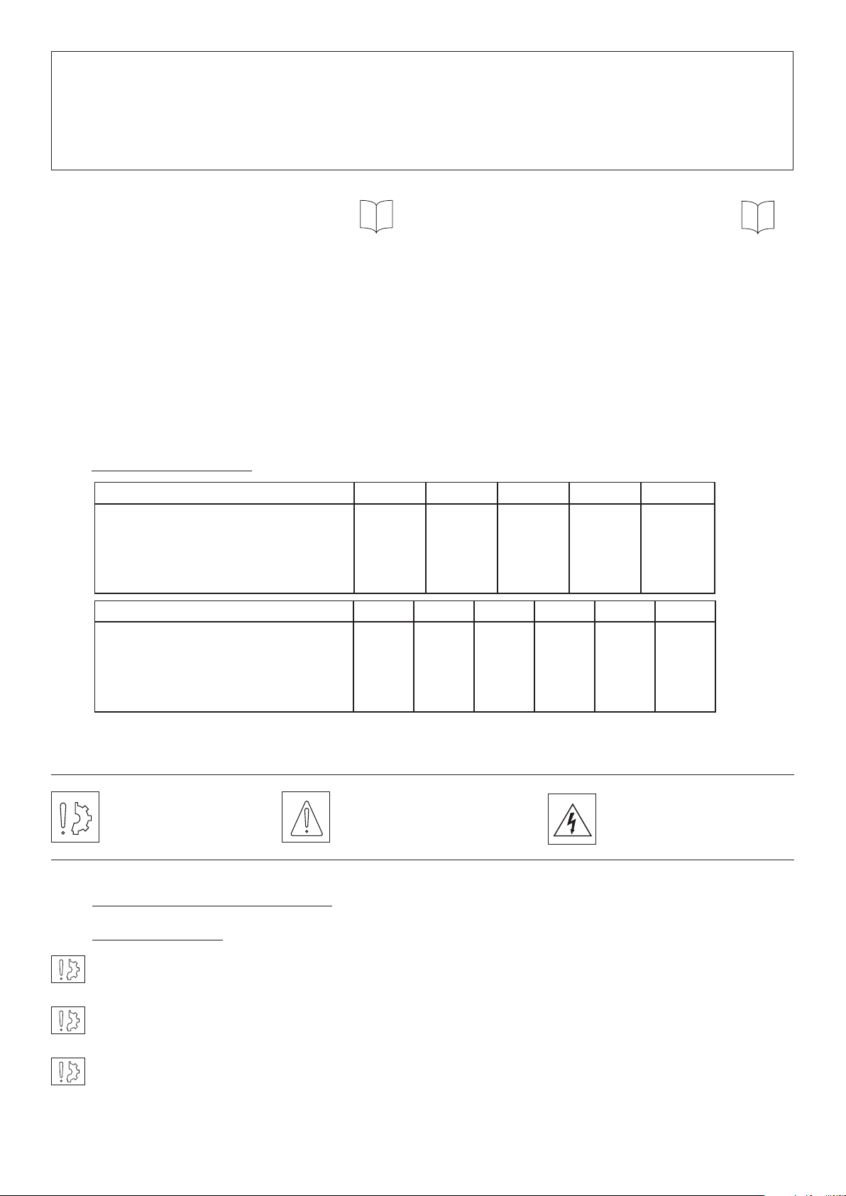
Symbol designating
an action that might
damage the brake
Symbol designating an
action that might be
dan gerous to human safety
Symbol designating an
elec trical action that might be
dangerous to human safety
2 Precautions and restrictions on use
2.1 Restrictions on use
These clutches are designed to run in oil. Dry running will cause premature wear in the disc set.
Exceeding the maximum rotation speed given in the catalogue invalidates the warranty.
These clutches are designed solely to run on a horizontal shaft.
2 Warner Electric Europe • +33 (0)2 41 21 24 24 P-2066-WE • 2/13
Page 3

2.2 Precautions in use and safety measures
During maintenance work, ensure that the mechanism to be driven by the clutch is at rest and that there is
no risk of it being started accidentally. All intervention have to be made by qualified personnel, owning this
manual.
Any modification made to the brake without the express authorisation of a representative of Warner Electric,
in the same way than any use out of the contractual specifications accepted by “Warner Electric”, will
result in the warranty being invalidated and Warner Electric will no longer be liable in any way with regard to
conformity.
3 Installation
3.1 Transport / storage
These units are supplied as standard in packaging guaranteeing protection for a period of 6 months by land
or air transport, or after transport by ship to neighbouring continents (without crossing the tropics).
3.2 Handling
The clutch is supplied assembled with the drive flange not fixed.
Avoid any impact on the units so as not to alter their performance.
3.3 Setting up
The hub (515) is normally supplied at tolerances H7 for the bore and P9 for the width of the keyway (In
accordance with NF E 22-175/DIN 6885/BS 4235/ISO R773).
The drive flange (529) is generally supplied at a bore H7 but without fixing holes.
We recommend a tolerance h6 for the shaft and an adjustment H7/f7 for the flange.
In cases where two coaxial shafts are fitted, the maximum authorised set-over is 0,05 mm. The angular
misali gnment should not exceed 0,1 mm over a length of 100 mm.
If these values cannot be attained, we recommend that an elastic coupling is fitted between the drive and
receiving parts.
• Put the drive flange (529) in place
After tightening to torque, do not forget to secure the bolts fixing the drive flange (529) with Loctite 243 or an
equivalent type of product.
• Slide the hub (515) onto the shaft (after adjusting the keyways) by positioning the teeth of the outer discs
(303) or (304) opposite the hollows in the drive flange (529)
Never directly strike the cylinder (401), closing flange (408), or hub (515), use a soft alloy block or drift
between these parts and the fitting device provided.
It is essential to comply with the length dimension “L ± 0,5” (see table 1) in order to prevent any risk of
contact between the drive flange (529) and the hub (515).
Warner Electric Europe • +33 (0)2 41 21 24 24 P-2066-WE • 2/13 3
Page 4

4 Maintenance
4.1 Maintenance
When operating conditions are complied with (running in oil, oil temperature, rotation speed, etc) the wear on
the H110 disc set is found to be negligible, in addition, it is automatically compensated for, until all the wear
adjustment available is used up, by movement of the piston. So this type of clutch needs little maintenance.
It is however necessary to:
• Change the oil after 40 h running from first use, then every year of normal running
• Regularly check the pressure chamber seal and in the event of leakage, or after 5 years use, change the
seals (701, 702)
• Check the wear on the disc set by measuring the travel of the piston (402), using table 2, below
Size 100 200 400 800 1600
Initial travel
nominal (mm)
Travel, clutch
worn - max. (mm)
3 2,5 2,5 3 3
5,5 5 5 7 7,5
Size 3200 6400 12800 25600 51200 102400
Initial travel
nominal (mm)
Travel, clutch
worn - max. (mm)
5 5 5 5 6 6
10 11,5 12,5 14,5 17,5 17,5
4.2 Spare parts
All orders for spare parts must state the size of the unit with its code number, the reference number of the
part (see appendice), and the quantity of each component wanted.
4.3 Dismantling / reassembling
During maintenance work, ensure that the mechanism to be driven by the clutch is at rest and that there is no
risk of it being started accidentally. Also ensure that the hydraulic supply is shut off.
Dismantling:
• Remove the fixing screws from the cylinder (401) or closing flange (408)
• Remove the cylinder (401) or closing flange (408)
• Take out the piston (402)
• Remove the worn disc set
• Fit a new disc set
4 Warner Electric Europe • +33 (0)2 41 21 24 24 P-2066-WE • 2/13
Page 5

Start with an inner disc, then an outer disc, and then alternate, ending of necessity with an inner disc.
For size 3200, after the last inner disc add the thrust disc (310 ).
• Change the seals (701, 702)
• Refit the piston (402)
• Refit the cylinder (401) or closing flange (408)
Take care not to damage the seals while reassembling
• Replace the cylinder (401) or closing flange (408) fixing screws, tighten them to the torque shown in
table 3, below and secure them with Loctite 243 or an equivalent type of product
Size 100 200 400 800 1600 3200 6400 12800 25600 51200 102400
Screw M4 M5 M6 M8 M10 M10 M14 M16 M20 M24 M24
Torque (Nm) 2,6 5,2 9,1 22 44 44 121 189 370 637 637
Table 3
5 Hydraulic connection
5.1 Important recommendations
Ensure that working pressures are complied with, to get the nominal performance from the equipment.
Do not exceed the maximum pressures (seetable 1).
We recommend control oil filtration of about 10 microns in order to guarantee trouble-free operation and full
life for the hydraulic components.
The disc lubricating oil should not exceed a running temperature of 80°C.
5.2 Hydraulic oils
The types of oil to be used for lubricating the discs should meet the following criteria:
• Good rust resistance
• No friction modifying additive
• No additive that might corrode the bronze friction surfaces (1a or 1b NF M 07-015)
• Compatible with materials used for hydraulic seals
• High viscosity index (>80)
The oils listed below (see table 4) meet these characteristics. The list is not exhaustive and other lines may
be added to it. The viscosity of the oil to be selected varies depending on the running temperature and speed
(measured on the outer diameter of the piston).
Size Mineraloil ATF
Viscosity
Running Speed
BP
ESSO
MOBIL
SHELL
ELF
ISO VG 22
> 12 m/s
Nuto H22
DTE 22
Tellus 22
ISO VG 32
> 12 m/s
Energol HLP-D32
Nuto h 32
DTE Oil Light
Tellus 32
Polytelis 32
ISO VG 46
> 12 m/s > 12 m/s
Energol HLP-D46
Nuto H 46
Autran MBX
AT Dexron II
DTE Oil Medium
Tellus 46
Donax TM Elfmatic
Polytelis 46
ATF 220
G2”
Table 4
Warner Electric Europe • +33 (0)2 41 21 24 24 P-2066-WE • 2/13 5
Page 6

5.3 Connection diagram
g
h
d
c
M
Figure 2 : Basic circuit
Fig 2
a: Tank
b: Pump
f
c: Filter
d: Pressure gauge
e
e: Pressure restrictor
f: Distributor
g: Revolving seal
h: Clutch
The clutch is lubricated by a drip-feed of oil that is not recycled.
b
a
Figure 3 : Circuit with progressive* clutch and external
Fig 3
lubrication of the disc set
a: Tank
m
g
h
f
n
b: Pump
c: Filter
d: Pressure gauge
e: Pressure restrictor
f: Distributor
g: Revolving seal
d
e
h: Clutch
k: Flow restrictor
m: Flow restrictor with non-return valve
c
M
b
a
k
n: accumulator with safety unit, clutch speed is adjusted by
means of the restrictor m and the non-return valve enables quick
de-clutching.
Once the clutch is engaged, it is retained by the accumulator n.
Excess control oil is used to top up the clutch drip-feed.
Figure 4 : Circuit with lubrication via the shaft
Fig 4
g
h
r
q
o
d
f
n
e
In the event of especially tough running conditions, equipment can
be supplied for lubrication via the shaft.
This requires additional machining of the clutch and the use of a
hydraulic circuit including a 2-way rotating seal (1 way pressure and
1 way sprinkling) and an air or water cooler.
a: Tank h: Clutch
b: Two-stage pump n: Accumulator with safety
cp
M
b
a
c: Filter unit
d: Pressure gauge o: Calibrated non-return valve
e: Pressure restrictor p: Filter
f: Distributor q: Distributor
g: 2-way rotating seal r: Cooler
* Ask our technical department for details of progressive clutch conditions depending on use.
6 Warner Electric Europe • +33 (0)2 41 21 24 24 P-2066-WE • 2/13
Page 7

6 Appendice
6.1 Diagram
529
3097 02
402
Stroke measurement
Ref. Nr Description
303
309
310
370
401
402
408
515
529
701
702
703
704
740
Steel outer disc
Steel inner disc
Thrust disc ( SZ3200)
Pressure ring
Cylinder
Piston
Closing ange
Hub
Driving ange
Cylinder ‘O’ ring seal
Piston ‘O’ ring seal
Cylinder quad ring seal
Piston quad ring seal
Spring
7 Troubleshooting
Sizes
100-1600
740
F
515
370
Sizes
3200-51200
701
View F
408
702
701
303310
L
401402
Stroke measurement
90°
Troubleshooting
Problem Possible Reason Action
• Hydraulic pressure too low
• Fault in the hydraulic circuit
• Faulty pressure chamber seals
The Clutch Slips
• Wrong lubricating oil
• Discs worn or damaged
• Check that nominal pressure is complied with (see table 1)
• Check it
• Check the condition of the contact surface (scratches,
foreign particles, etc.) clean, change the seals
• Change the oil in accordance with the data given in table 4
• Change the discs - Check the condition of the receiving
parts’ teeth (hub, ange)
Oil temperature
over 80ºC
Subject to alteration without prior notice
• Running speed too high
• Too little cooling oil
• Reduce the speed - Adopt oil circulation
• Adopt oil circulation - Increase ow, where possible
Warner Electric Europe • +33 (0)2 41 21 24 24 P-2066-WE • 2/13 7
Page 8

Warranty
Warner Electric LLC warrants that it will repair or replace (whichever it deems advisable) any product manufactured and
sold by it which proves to be defective in material or workmanship within a period of one (1) year from the date of original
purchase for consumer, commercial or industrial use.
This warranty extends only to the original purchaser and is not transferable or assignable without Warner Electric LLC’s
prior consent.
Warranty service can be obtained in the U.S.A. by returning any defective product, transportation charges prepaid, to
the appropriate Warner Electric LLC factory. Additional warranty information may be obtained by writing the Customer
Satisfaction Department, Warner Electric LLC, 449 Gardner Street, South Beloit, Illinois 61080, or by calling 815-389-
3771.
A purchase receipt or other proof of original purchase will be required before warranty service is rendered. If found
defective under the terms of this warranty, repair or replacement will be made, without charge, together with a refund for
transportation costs. If found not to be defective, you will be notified and, with your consent, the item will be repaired or
replaced and returned to you at your expense.
This warranty covers normal use and does not cover damage or defect which results from alteration, accident, neglect, or
improper installation, operation, or maintenance.
Some states do not allow limitation on how long an implied warranty lasts, so the above limitation may not apply to you.
Warner Electric LLC’s obligation under this warranty is limited to the repair or replacement of the defective product and
in no event shall Warner Electric LLC be liable for consequential, indirect, or incidental damages of any kind incurred by
reason of the manufacture, sale or use of any defective product. Warner Electric LLC neither assumes nor authorizes any
other person to give any other warranty or to assume any other obligation or liability on its behalf.
WITH RESPECT TO CONSUMER USE OF THE PRODUCT, ANY IMPLIED WARRANTIES WHICH THE CONSUMER MAY
HAVE ARE LIMITED IN DURATION TO ONE YEAR FROM THE DATE OF ORIGINAL CONSUMER PURCHASE. WITH
RESPECT TO COMMERCIAL AND INDUSTRIAL USES OF THE PRODUCT, THE FOREGOING WARRANTY IS IN LIEU
OF AND EXCLUDES ALL OTHER WARRANTIES, WHETHER EXPRESSED OR IMPLIED BY OPERATION OF LAW OR
OTHERWISE, INCLUDING, BUT NOT LIMITED TO, ANY IMPLIED WARRANTIES OF MERCHANTABILITY OR FITNESS.
Some states do not allow the exclusion or limitation of incidental or consequential damages, so the above limitation or
exclusion may not apply to you. This warranty gives you specific legal rights and you may also have other rights which
vary from state to state.
Changes in Dimensions and Specications
All dimensions and specifications shown in Warner Electric catalogs are subject to change without notice. Weights do not
include weight of boxing for shipment. Certified prints will be furnished without charge on request to Warner Electric.
Warner Electric Europe
7 rue Champfleur, B.P. 20095, St Barthelemy d’Anjou - France
+33 (0)2 41 21 24 24 • Fax: +33 (0)2 41 21 24 70
www.warnerelectric.com
Printed in USAP-2066-WE • 2/13
 Loading...