

Page 1

FM Series Foot Mounted Load Cells
AC10 Measuring System
A30 Single Range Tensioncells
B30 Single Range Tensioncells
C30 Single Range tensioncells
P-2012
Installation Instructions
Page 2

Contents
FM Series Foot Mounted Load Cells. . . . . . . . 3
Specifications . . . . . . . . . . . . . . . . . . . . . . . 4
Wiring Hookup . . . . . . . . . . . . . . . . . . . . . . 5
System Example. . . . . . . . . . . . . . . . . . . . . 5
Dimensions . . . . . . . . . . . . . . . . . . . . . . . . . 6
AC10 Measuring System. . . . . . . . . . . . . . . . . 7
Introduction. . . . . . . . . . . . . . . . . . . . . . . . . 8
System Overview . . . . . . . . . . . . . . . . . . . . 9
AC10 Tensioncells. . . . . . . . . . . . . . . . . . . 10
AC10 Electronics . . . . . . . . . . . . . . . . . . . 11
AC10 Specifciations . . . . . . . . . . . . . . . . . 12
Installation. . . . . . . . . . . . . . . . . . . . . . . . . 14
Pre-Installation . . . . . . . . . . . . . . . . . . . . . 14
Mechanical Installation . . . . . . . . . . . . . . . 14
Electrical Installation. . . . . . . . . . . . . . . . . 16
Electrical Connections . . . . . . . . . . . . . . . 16
Initial Electrical Checks. . . . . . . . . . . . . . . 18
AC10 Set up Procedure . . . . . . . . . . . . . . 19
Programmable Treshold Relay . . . . . . . . . 21
Reset Tare to Zero . . . . . . . . . . . . . . . . . . 21
Troubleshooting . . . . . . . . . . . . . . . . . . . . 22
Dimension Drawings. . . . . . . . . . . . . . . . . 24
AC10 Tensioncells. . . . . . . . . . . . . . . . . . . 24
Model Number Designation . . . . . . . . . . . 24
PSAC10. . . . . . . . . . . . . . . . . . . . . . . . . . . 24
C30 Single Range Tensioncells . . . . . . . . . . . 49
General Information . . . . . . . . . . . . . . . . . 50
Installation and Operation. . . . . . . . . . . . . 54
Adjustments . . . . . . . . . . . . . . . . . . . . . . . 56
Troubleshooting . . . . . . . . . . . . . . . . . . . . 56
Recalibration. . . . . . . . . . . . . . . . . . . . . . . 57
Dimension Drawing. . . . . . . . . . . . . . . . . . 59
Warranty. . . . . . . . . . . . . . . . . . . . . . Back Page
Failure to follow these instructions may result in product damage, equipment damage, and serious or fatal injury to
personnel.
A30 Single Range Tensioncells . . . . . . . . . . . 27
General Information . . . . . . . . . . . . . . . . . 28
Installation and Operation. . . . . . . . . . . . . 31
Adjustments . . . . . . . . . . . . . . . . . . . . . . . 33
Troubleshooting . . . . . . . . . . . . . . . . . . . . 34
Recalibration. . . . . . . . . . . . . . . . . . . . . . . 35
Dimension Drawing. . . . . . . . . . . . . . . . . . 36
B30 Single Range Tensioncells . . . . . . . . . . . 37
General Information . . . . . . . . . . . . . . . . . 38
Installation and Operation. . . . . . . . . . . . . 42
Adjustments . . . . . . . . . . . . . . . . . . . . . . . 43
Troubleshooting . . . . . . . . . . . . . . . . . . . . 44
Recalibration. . . . . . . . . . . . . . . . . . . . . . . 45
Dimension Drawing. . . . . . . . . . . . . . . . . . 47
Warner Electric • 800-825-9050 P-2012
2
Page 3

P-2012-1
819-0401
FM Series Foot Mounted Load Cells
Warner Electric • 800-825-9050 P-2012-1
3
Page 4
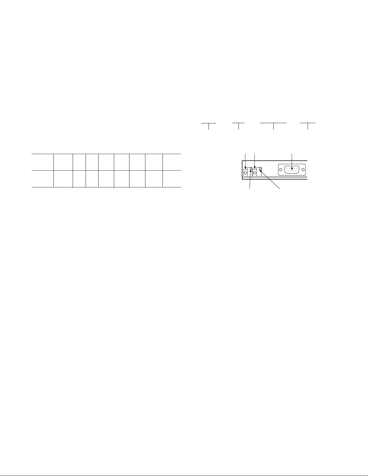
The FM style load cell provides easy and conven-
Zero setting:
Green LED ON
above 0 VDC
Gain setting:
Green LED ON
below 5 VDC
Green LED D-Sub connector
ient mounting to the roll that is being measured
(used with pillow blocks). The load cell is a strain
gauge style unit that is ideal for heavy tension
applications. It can be mounted regardless of orientation, but has to work in compression. Only
the perpendicular force (resultant) is measured by
the load cell. The perpendicular force can be at a
maximum permitted angle of +/- 30 degrees.
Correct load cell sizing must be adhered to so
potential overload forces do not damage cells.
FM Series Part Numbers
F M 0 1 - 1 0 0 0 - A C
Specifications:
Load
Ratings N 100 250 500 1000 2500 5000 10000
(Lbs.) (22) (56) (112) (225) (562) (1124) (2248)
Size 01 01 01 01 01 01 02
Input Power
±12 to ±15 VDC
@ 45 MA ±5%
Output Signal
5VDC output at rated load
Temperature Range
0-70 degrees C
(32 -158 degree F)
Temperature drift
0.1 % of rating per degree C
Non-linearity and Repeatability
< 0.5%
Power Consumption
1 Watt
Cable
16 ft. provided with load cell
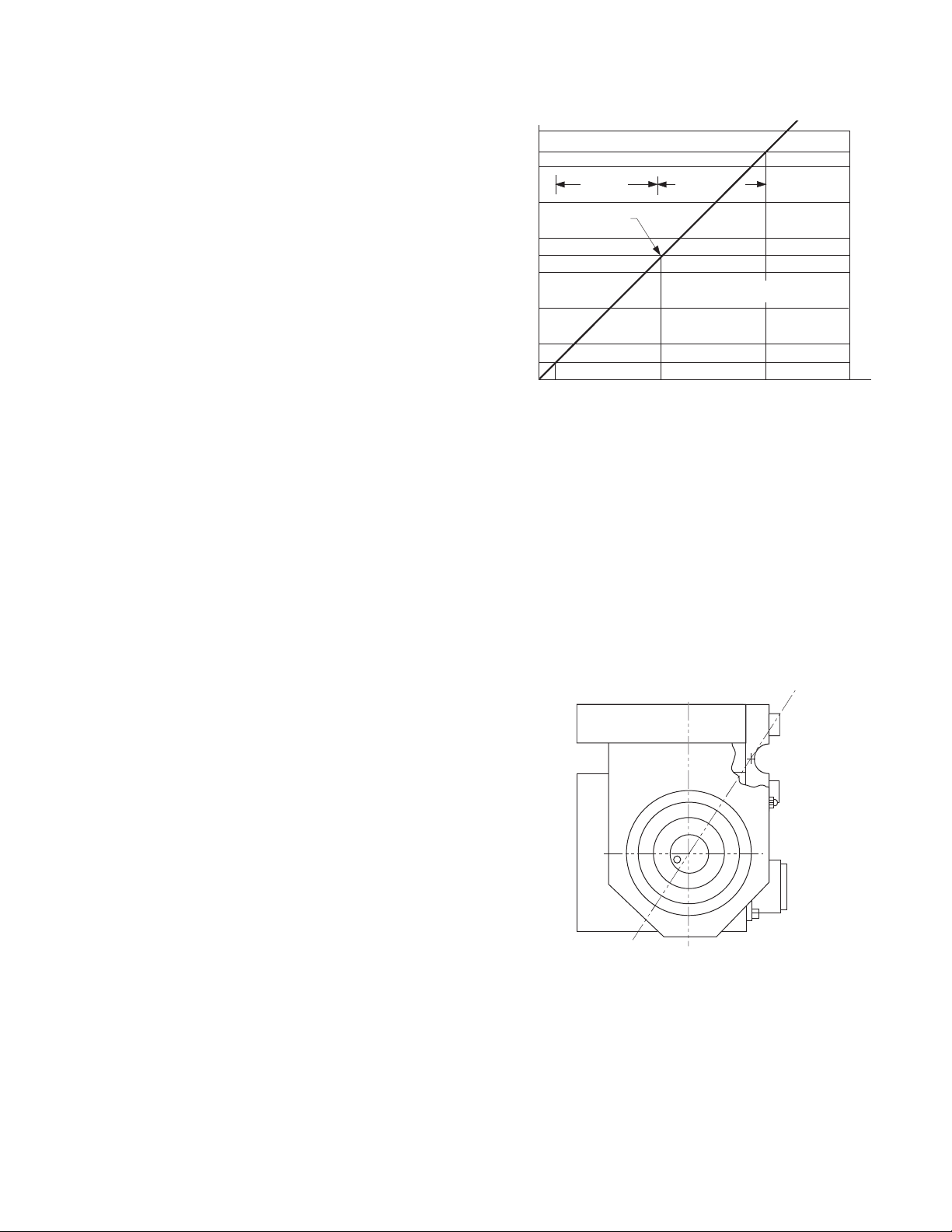
Maximum Load Ratings (See Figure 6)
Overload
120% of rated load
Compression Overload
150% of rated load
Horizontal Load
50% of rated load
Model Numbers/Part Numbers
FM01-100 6910-840-100
FM01-250 6910-840-102
FM01-500 6910-840-104
FM01-1000 6910-840-106
FM01-2500 6910-840-108
FM01-5000 6910-840-110
FM01-10K 6910-840-112
Warner Electric • 800-825-9050 P-2012-1
4
Model Size Load in N Amplifier built in
Alignment
Figure 1
The sensor has been factory calibrated:
0VDC (No load)
5VDC (Rated load)
Two potentiometers and LED’s are located near
the “D” connector (See Figur
cation. When used in the nominal range, both
LED’s are “ON”. Although the load cell has been
factory calibrated. The unit may be rescaled if
necessary. It is recommended that a qualified
technician do this procedure.
Attach a digital volt meter between the signal
lead (yellow) and 0VDC (ground). With no load
on the cell adjust the zero potentiometer for a
0VDC output. The zero setting LED should be
“OFF”. Any voltage above 0VDC, the zero LED
will turn “ON”.
Apply the mazimum load to the cell. Adjust the
gain potentiometer for a 5VDC output reading.
The gain LED should be “OFF” at a 5VDC output
level. Remove the load and insure the gain LED
is “ON”.
The zero and gain adjustments may need to be
repeated a couple of times to insure proper setting.
e 1) for visual indi-
Page 5
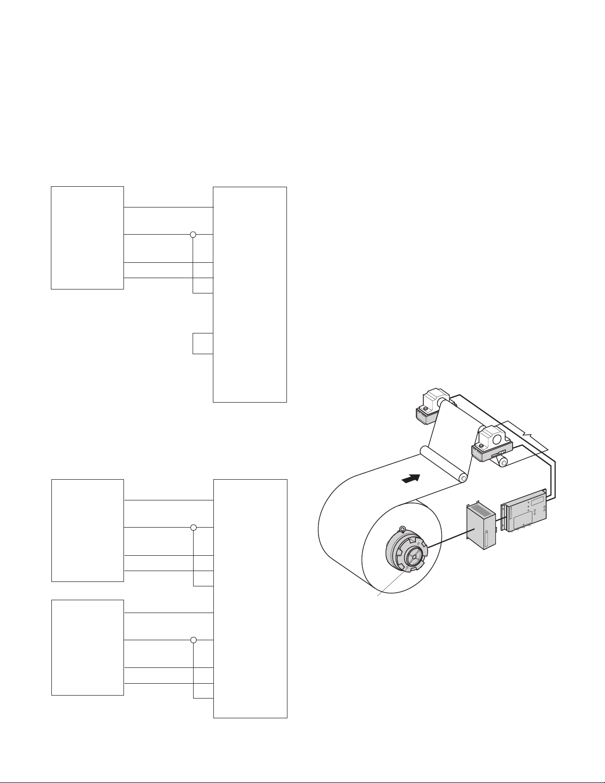
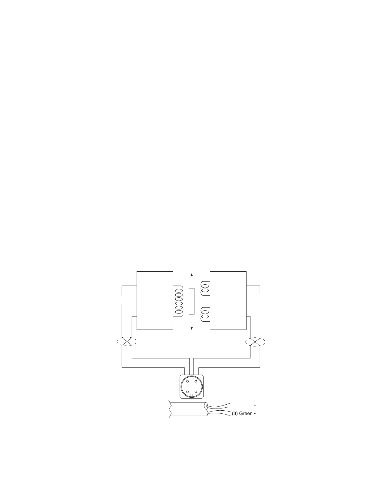
Wiring Hookup:
Red (+15V)
White (Ground)
Yellow (Signal)
BLUE (-15V)
+UCELL/SEN+
CELL1+/SENS IN
CELL1-
-UCELL/SENS
Ground (OV)
Shield
+UCELL
CELL2+
CELL2-
-UCELL
SHIELD
FM Series Load Cell
MCS2000-CTLC
No Connection
No Connection
No Connection
No Connection
Add Jumper
Red (+15V)
White (Ground)
Yellow (Signal)
Blue (-15V)
+UCELL/SEN+
CELL1+/SENS IN
CELL1-
-UCELL/SENS
Ground (OV)
Shield
+UCELL
CELL2+
CELL2-
-UCELL
Ground (OV)
Shield
Red (+15V)
White (Ground)
Yellow (Signal)
Blue (-15V)
N/C
N/C
FM Series Load Cell
FM Series Load Cell
MCS2000-CTLC
Magnetic Particle Brake
MCS2000-PSDRV
Power Supply
and Drive
MCS2000-
CTLC
FM Load
Cell
FM Load
Cell
The load cell requires a +15VDC and a -15VDC
power supply. The 5V/15V switch inside the
MCS2000-CTLC must set to +/-15VDC.
Terminate all unused wires from cable.
Wiring example using One Load Cell with the
MCS2000-CTLC contr
ol
Notes: It is recommended to use the load cell
in a compr
ession application. It must be fitted
on a flat surface in order to avoid original
sensitive plate stress. Do not load the sensor
before mounting it with screws on the
mounting surface.
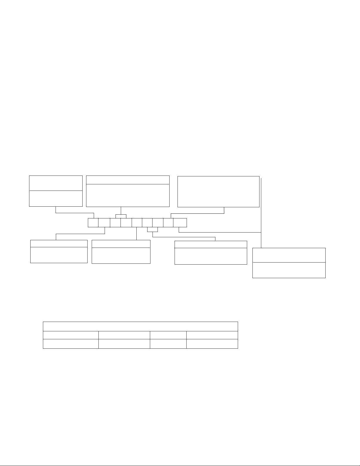
System Example:
FM Load Cell with an Electric Brake
This is a typical load cell unwind application
example. The electric brake varies the tension
on the web depending on the feedback fr
load cell. The load cell signal is amplified and
interpreted in the controller (MCS2000-CTLC).
The controller then puts out a corresponding
0-10 VDC signal to the power supply and drive
(MCS2000-PSDRV). The PSDRV then amplifies
and interprets the signal from the controller and
puts out a corresponding 0-24 VDC signal to the
brake to apply either more or less braking.
om the
Wiring example using 2 load cells with the
MCS2000-CTLC control
Warner Electric • 800-825-9050 P-2012-1
Figure 2
Figure 3
Figure 3
Figure 4
5
Page 6
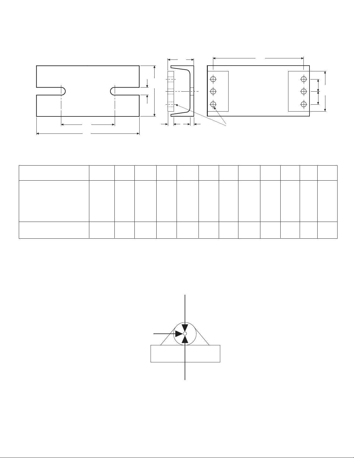
Dimensions
G
F
H
C
K
J
D
E
I
A
B
M10 Screw
11 mm dia. (6)
L
Max. extension overload =
120% from nominal load
Max. horizontal load =
50% from nominal load
Max. compression overload =
150% from nominal load
Tension sensor
FM Series
Foot mounted load cells
(–) Denotes millimeters
Size Load Ratings A B C D E F G H I J K L
N (lbs.)
100 (22)
250 (56)
01 500 (112) 4.055 7.874 6.890 .512 4.016 .984 .984 3.150 2.047 .472 .236 .433
1000 (225) (103) (200) (175) (13) (102) (25) (25) (80) (52) (12) (6) (11)
2500 (562)
5000 (1124)
5.591 8.858 7.677 .669 5.00 .984 .984 3.937 2.165 .709 .236 .433
02 10000 (2248) (142) (225) (195) (17) (127) (25) (25) (100) (55) (18) (6) (11)
Figure 5
Figure 6
Warner Electric • 800-825-9050 P-2012-1
6
Page 7

P-2012-2
819-0402
AC10 Measuring System
Warner Electric • 800-825-9050 P-2012-2
7
Page 8

Introduction
This manual is intended for use by qualified personnel to assist them in the safe setup and
operation of the Warner Electric AC10 Tension
Measuring System. Warner Electric has made
every effort to insure the accuracy and completeness of the information and recommends
that all procedures be read and understood
before performing them. Please contact Warner
Electric with any questions regarding any information contained in this manual.
Warner Electric • 800-825-9050 P-2012-2
8
Page 9
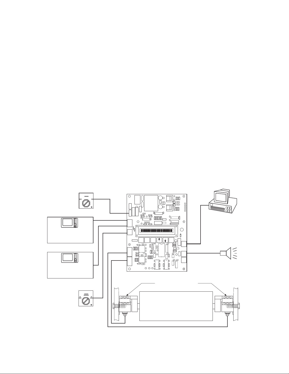
System Overview
J3
J4
J6
J5
Warner
Part# 80-165 Rev
Serial#
Setup
Rapid
Exit
Setup
Enter
J7
J8
J9
J1
J2
PSAC10 Board
Power
Switch
Output #1
Output #2
Control
Analog or Digital
Meter
Drive
Cell #1/Total/Cell #2
Switch
AC-10 Tensioncells
Threshold
Alarm
RS-422
Interface
MCS2000-CTDA
MCS2000-CTDA
Control
Analog or Digital
Meter
Drive
The AC10 Tension Measuring System is designed
to measure tension on continuous strip processing lines and equipment. The system consists of
two AC10 Tensioncells, the PSAC10 power supply
amplifier board, and two cables for connecting the
Tensioncells to the board.
AC10 Tensioncells are mounted in pairs, one at
each end of the measuring roll. During operation
the Tensioncells continuously measure the
mechanical tension force applied to the measuring
roll. When the force is applied, the load plate
deflects toward or away from the base block
depending on the resultant force acting upon the
Tensioncell. Deflection toward the base block is
defined as the "Compression Mode.” Deflection
away from the base block is defined as the
"Tension Mode." AC10 Tensioncells work equally
well in either mode.
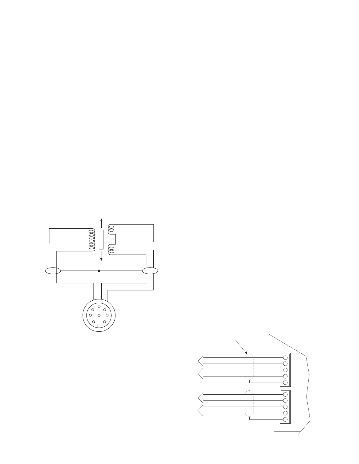
The mechanical deflection of the load plate is
converted into an electrical output signal by the
AC Linear Variable Differential Transformer
(LVDT). Displacement of the LVDT core caused
by variations in web tension results in an output
signal to the PSAC10 board directly proportional
to the applied tension.
The analog outputs from the Tensioncells are converted into digital signals by the microprocessorbased electronics. The signals are conditioned,
processed, and summed to produce two individually scaleable, -10 to +10 volt DC analog outputs
to a tension indicator, drive or a MCS2000 CTDA
control which can be used to monitor or control
tension. The percent tension applied to each
Tensioncell and the total tension are displayed on
the board mounted 16-character liquid crystal
display (LCD).
Terminals are also provided for connecting a user
supplied On/Off power switch, 1-only 2-only
switch, and RS-422 PC interface. A threshold
alarm relay connection is also provided.
Note: When using the PSAC10 board, connect the outputs to the MCS2000 CTDA. There is no
need to use the MCS2000 CTLC, because the signal is amplified and summed in the PSAC10.
Warner Electric • 800-825-9050 P-2012-2
9
Page 10
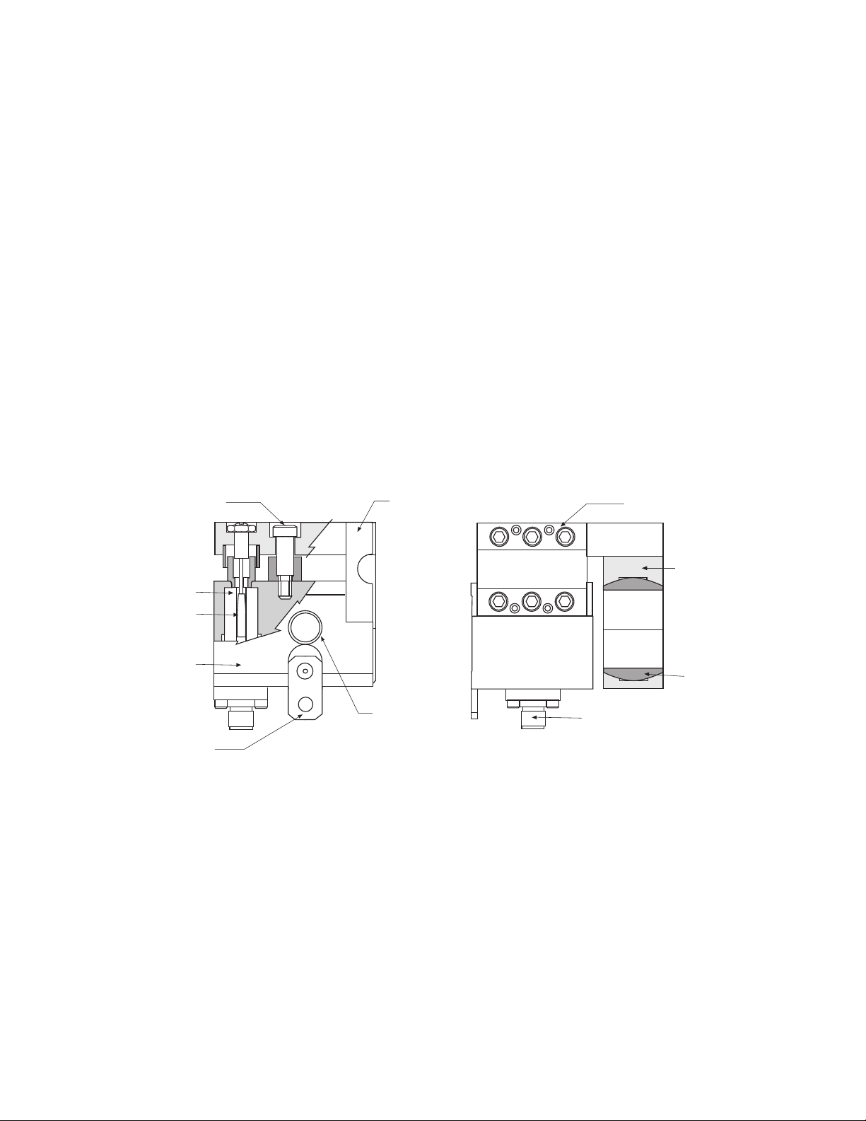
AC10 Tensioncells
Shaft Support
Block
Self-Aligning
Shaft Support
Bushing
Electrical
Connector
5/8-1 1 UNC
Mounting
Hole
Load Plate
C-Flexure
Mechanical Stop
LVDT
LVDT Core
Base Block
Locating Tab
AC10 Tensioncells are available in three capacity ranges for non-rotating shaft applications
with maximum resultant force plus tare load of
60, 170, or 500 pounds respectively.
The rugged, all-steel construction of the AC10
Tensioncell includes four basic components: the
one-piece base block, the patented C-Flexure,
the load plate, and the shaft support block. The
factory-set mechanical stop provides overload
protection up to ten times the maximum rated
load capacity of the unit.
Each unit is wall mounted by means of a single
bolt located in line with the integral self-aligning,
stainless steel shaft support bushing and the
centerline of the roll shaft. This permits the
Tensioncell to be rotated and mounted at the
required angle around the axis of the measuring
roll. The locating tab at the bottom of the unit
locks it in position.
The primary conversion element between the
mechanical tension force and the electrical output signal is an AC Linear Variable Differential
Transformer (LVDT). The LVDT electrical elements are encapsulated and sealed against
shock, vibration, or tampering. Input and output
circuits are isolated from each other and from
the Tensioncell body. This permits the
Tensioncells to be used in floating ground electrical systems.
10
Warner Electric • 800-825-9050 P-2012-2
Page 11
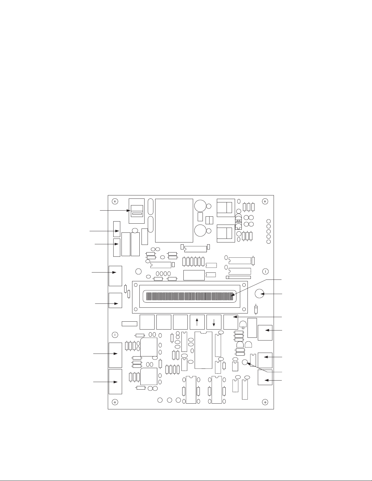
AC10 Electronics
J3
J4
J6
J5
Warner
Part# PSAC10
Serial#
Setup
Rapid
Exit
Setup
Enter
J7
J8
J9
J1
J2
Input Power
Selector Switch
Input Power
Terminal
Power On
Switch Terminal
Output #1
Output #2
Terminal
Cell #1/T otal/Cell#2
Switch Terminal
Tensioncell #1
Terminal
Tensioncell #2
Terminal
16-Character LCD
LCD Brightness
Adjustment
Pushbutton Keys
Threshold Relay
Terminal
RS-422 Output
Terminal
Run Mode LED
Spare
230V
The AC10 microprocessor-based electronics
adds ease of setup, versatility, and accuracy of
the overall system by eliminating the need for
potentiometers to adjust or setup the system.
All adjustments and system settings are performed by using the pushbutton keys on the
board. During setup, alphanumeric prompts are
displayed on the 16-character LCD to guide the
user through the setup procedure.
Other features of the PSAC10 board include:
Two individually scaleable -10 to +10 volt DC
outputs
Run Mode LED
Programmable threshold relay
Cell#1/Total/Cell#2 switch connection
LCD Brightness Adjustment
Switch selectable 115/230 volt AC input
power
An RS422 Serial Output terminal is also provided for interfacing the AC10 system with a PC to
monitor and/or record the percent tension
applied to each Tensioncell. Data is transferred
in ASCII text format. The RS422 output can be
converted to RS-232.
Warner Electric • 800-825-9050 P-2012-2
11
Page 12

Specifications
AC10 Tensioncells
Dimensions (I x w x h) . . . . . . . . . . . . . . . . . . . . . . . . . . . . . . . . . . . . . . . . . . . . . . . .3.00" x 3.44" x 3.90"
Maximum Load Capacity (tension plus tar
AC10A . . . . . . . . . . . . . . . . . . . . . . . . . . . . . . . . . . . . . . . . . . . . . . . . . . . . . . . . . . . . . . . . . . .60 pounds
AC10B . . . . . . . . . . . . . . . . . . . . . . . . . . . . . . . . . . . . . . . . . . . . . . . . . . . . . . . . . . . . . . . . . .170 pounds
AC10C . . . . . . . . . . . . . . . . . . . . . . . . . . . . . . . . . . . . . . . . . . . . . . . . . . . . . . . . . . . . . . . . . .500 pounds
Minimum Tension Load Required for Setup
AC10A . . . . . . . . . . . . . . . . . . . . . . . . . . . . . . . . . . . . . . . . . . . . . . . . . . . . . . . . . . . . . . . . . . . . .4 pounds
AC10B . . . . . . . . . . . . . . . . . . . . . . . . . . . . . . . . . . . . . . . . . . . . . . . . . . . . . . . . . . . . . . . . . . .10 pounds
AC10C . . . . . . . . . . . . . . . . . . . . . . . . . . . . . . . . . . . . . . . . . . . . . . . . . . . . . . . . . . . . . . . . . . .30 pounds
Standard Shaft Diameters (1/16" increments) . . . . . . . . . . . . . . . . . . . . . . . . . . . . . . . . . . . .1/2" to 1-1/2"
Overload Protection . . . . . . . . . . . . . . . . . . . . . . . . . . . . . . . . . . . . .10 times maximum rated load of unit
Maximum Deflection at Full Load . . . . . . . . . . . . . . . . . . . . . . . . . . . . . . . . . . . . . . . . . . . . . . . . . .0.010"
LVDT
Operating Temperature . . . . . . . . . . . . . . . . . . . . . . . . . . . . . . . . . . . . . . . . . . . . . . . . .250°F maximum
Excitation Voltage . . . . . . . . . . . . . . . . . . . . . . . . . . . . . . . . . . . . . . . . . . . . . . . . . . . . . .15 Vrms @5KHz
Output . . . . . . . . . . . . . . . . . . . . . . . . . . . . . . . . . . . . . .3.2 volts AC/inch displacement / volt excitation
Excitation Resistance . . . . . . . . . . . . . . . . . . . . . . . . . . . . . . . . . . . . . . . . . . . . . . . . . . .335 Ohms ±5%
Output Signal Resistance . . . . . . . . . . . . . . . . . . . . . . . . . . . . . . . . . . . . . . . . . . . . . . . .100 Ohms ±5%
Linearity . . . . . . . . . . . . . . . . . . . . . . . . . . . . . . . . . . . . . . . . . . . . . . . . . . . . . . . . . . . . . .0.1% of full scale
Hysteresis . . . . . . . . . . . . . . . . . . . . . . . . . . . . . . . . . . . . . . . . . . . . . . . . . . . . . . . . . . . .0.1% of full scale
Repeatability . . . . . . . . . . . . . . . . . . . . . . . . . . . . . . . . . . . . . . . . . . . . . . . . . . . . . . . . . .0.1% of full scale
Temperature Drift . . . . . . . . . . . . . . . . . . . . . . . . . . . . . . . . . . . . . . . . . . . . . . . . . . . . . . . . . .0.02% per °C
PSAC10 Power Supply/Amplifier Board
Dimension (I x w) . . . . . . . . . . . . . . . . . . . . . . . . . . . . . . . . . . . . . . . . . . . . . . . . . . . . . . . . . .8.75" x 6.88"
Maximum
height of components above board . . . . . . . . . . . . . . . . . . . . . . . . . . . . . . . . . . . . . . . . . . .1.5"
Operating Temperature Range . . . . . . . . . . . . . . . . . . . . . . . . . . . . . . . . .32°F to +160°F (0°C to +70°C)
Input Voltage (switch selectable) . . . . . . . . . . . . . . . . . . . . . . . . . .115/230 VAC, 50-60 Hz, <1.0 Ampere
Output Voltage (two individually scaleable) . . . . . . . . . . . . . . . . . . . . . . . . . . . . . . . . . . . .-10 to +10 VDC
Maximum cable distance between Tensioncell and board . . . . . . . . . . . . . . . . . . . . . . . . . . . . . .100 feet
(The output load to the board must be 2 kΩ or greater)
Threshold Relay Contact . . . . . . . . . . . . . . . . . . .1A @ 24 VDC, 500mA@ 120 VAC, 250 mA @ 220 VAC
RS-422 Data Rate . . . . . . . . . . . . . . . . . . . . . . . . . . . . . . . . . . . . . . . . . . . . . . . .300bps, NP, 8, 1 stop bit
e)
Warner Electric • 800-825-9050 P-2012-2
12
Page 13

Pushbutton Key Functions
The six pushbutton keys on the PSAC10 board are used to enter and exit the Setup Mode and to
make adjustments during the procedure. This section describes the various key functions and combinations that are used while setting up the system.
The UP arrow key is used to toggle between selections. It is also used to incremental-
RAPID
ly increase the output voltage each time the key is pressed. When the UP arrow and
RAPID keys are pressed simultaneously, the voltage value will change continuously
until the keys are released or the upper limit is reached. (See note below.)
ENTER
SETUP
EXIT
SETUP
RAPID
ENTERSETUP
RAPID
The DOWN arrow key is used to toggle between selections and to incrementally
decrease the output voltage each time the key is pressed. When the DOWN arrow and
RAPID keys are pressed simultaneously, the voltage value will change continuously
until the keys are released or the lower limit is reached. (See note below.)
The ENTER key is used to make selections and store values before proceeding to the
next Setup step.
Pressing and releasing these keys simultaneously accesses the Setup Mode. An asterisk (*) will display next to the right tension value.
Press and release these keys simultaneously to start the Setup procedure when in the
Setup Mode.
Press and release this key to exit the Setup Mode at any time. The system will return
the settings entered during the last completed setup procedure.
Press and release these keys simultaneously to enter the settings for the
Programmable Alarm Output.
SETUP
EXIT
Press and release these keys simultaneously to zero the system.
Note: During setup, the output voltage value will change approximately 5 millivolts each time the
Up or Down arr
ow key is pressed and released. Pressing and releasing the RAPID key and the
Up or Down arrow key simultaneously will change the value approximately 200 millivolts.
Holding the Rapid key and an arrow key in, will continuously change the value until the keys are
released.
Warner Electric • 800-825-9050 P-2012-2
13
Page 14
Installation
T
E
B
TW
T
RF
L
O
Tensioncell Model Number Designation
AC10B 18 W1
Code
A
B
C
Max. Load
Capacity
(pounds)
60
170
500
Min. Tension
Load for Setup
(pounds)
4
10
30
Example: AC10B18W1
AC10 = Side Mount Tensioncell
B = 170 pound capacity
18 = 1-1/8 inch shaft diameter
W1 = AC10 with split brushing
Support Bushing (AC10 only)
W1 = Split bushing for clamping
W2 = Solid bushing for expansion
08 1/2
09 9/16
10 5/8
11 11/16
12 3/4
13 13/16
14 7/8
15 15/16
16 1
17 1-1/16
18 1-1/8
19 1-3/16
20 1-1/4
21 1-5/16
22 1-3/8
23 1-7/16
24 1-1/2
Shaft Diameter
Pre-Installation Inspection
Before installing the AC10 system:
1. Insure all components are present. A typical
system consists of two AC10 Tensioncells,
one PSAC10 board, and two 30 foot lengths
of cable for connecting the Tensioncells to
the board. Refer to Model Number
Designation (Chart 1) below to verify load
capacity and shaft diameter.
2. Inspect all electrical and mechanical components for physical damage.
3. Promptly report any damage to the carrier
and Warner Electric.
Mechanical Installation – Tensioncells
The maximum rated load capacity must be
greater than or equal to (RF + TW) where W =
Tare Weight. The Web Resultant Force (RF) and
Tare Weight are always summed. Refer to the
Model Number Designation (Chart 1) below to
verify the shaft diameter, and that the maximum
rated load capacity of each unit.
Warner Electric also recommends the Resultant
Force (RF) be greater than 1/3 the maximum
load capacity of the Tensioncells.
Warner Electric side mount AC10 Tensioncells
are shipped in pairs designated W1 and W2.
The W1 unit has a split stainless steel, selfaligning bushing for clamping the measuring
roll. The bushing in the W2 unit is not split to
allow for shaft expansion.
AC10 Tensioncells are available in three capacity ranges. The rated load capacity should
always be larger than the maximum calculated
Tare Weight (W) plus the Resultant Force (RF).
To calculate the Resultant Force:
1. E = (180°-B/2) where B = Wrap Angle
2. RF = T x CosineE where T = Web Tension
Warner Electric • 800-825-9050 P-2012-2
14
Chart 1
Page 15
Before installing the Tensioncells, refer to
T
E
B
TW
T
RF
L
O
5/8-11 UNC
Mounting
Bolt
Machine
Frame
W1
Locating Tab
Centerline
Shaft Support
Block & Screws
W2
machine drawings, or other documentation
to determine the mounting angle. If the
mounting angle is not specified, mount the
Tensioncells so that the Tensioncell load line
(OL) bisects the wrap angle and aligns with
the Resultant Force (RF).
The Tensioncells are mounted to the machine
frame with a 5/8-11 UNC bolt. The bolt is in line
with the centerline of the shaft support bushing.
This allows the T
ensioncells to be rotated
around the centerline of the roll so that the
Tensioncell load line (OX) aligns with the
Resultant Force (RF).
To install the Tensioncells:
1. Drill a 5/8" diameter hole through each side
of the machine frame at the measuring roll
location. The holes must be in line with each
other and roll centerline to insure that the roll
is level.
2. Fasten the Tensioncell to the machine frame
with the 5/8-11 UNC mounting bolt.
3. Rotate the Tensioncell to the proper mount-
ing angle and tighten the mounting bolt.
4. Drill a #6 (.204) hole concentric with the 1/4"
hole in the locating tab.
5. Remove the Tensioncell to provide clearance
to tap the hole for a 1/4-20 thread.
6. Repeat steps 2 through 5 for the Tensioncell
for the other end of measuring roll shaft.
7. Loosen, but do not remove, the four screws
in the bottom of the shaft support block
enough to slide the Tensioncells on the roll
shaft.
Note: The mounting angle must be the
same for both T
ensioncells and the Load
Plate for both units must face in the same
direction.
8. Position the roll with the Tensioncells in the
machine and fasten them to the machine
frame with the mounting bolts. Tighten the
bolts enough to allow the T
ensioncells to be
rotated to the desired mounting angle.
9. Rotate the Tensioncells to align the locating
tab with the 1/4-20 threaded hole. Lock the
Tensioncells in position against the machine
frame using a 1/4-20 x 1/2 socket head cap
screw.
10. Tighten the mounting bolt on each unit.
11. Align the measuring roll so that there is no
mechanical binding or friction.
12. Tighten the four screws in the bottom of
each shaft support block.
Note: The mechanical stops are factory set
ovide 1000% overload protection.
to pr
Warner Electric • 800-825-9050 P-2012-2
15
Page 16
Electrical Installation
Oscillator
Demodulator
Shield to Pin H
Shield to Pin H
White to Pin G
Brown to Pin A
Pink to Pin E
Yellow to Pin C
Input
Output
P1
S1
S2
A
GH E C
A
H
G
C
D
E
FB
Sig
Sig
Exc
Exc
Gnd
Yellow
Pink
Brown
White
Shield
Yellow
Pink
Brown
White
Shield
Sig
Sig
Exc
Exc
Gnd
J2
J1
1
1
2
2
3
3
4
4
5
5
Electrical Connections
(Read the entire electrical installation procedure before proceeding.)
The PSAC10 Power Supply/Amplifier board
should be secur
ely mounted in a cabinet or
enclosure using the mounting holes and standoffs
INPUT provided. Refer to the dimension drawing
on Page 19 for mounting hole locations.
Two 30 foot cables are provided for connecting
the AC10 Tensioncells with the PSAC10 board. A
screw-on connector is provided at one end of
each cable for connecting to the AC10
Tensioncells.
Note: If the board must be located more than
30 feet away fr
om the Tensioncells, the cable
can be extended up to a total of 100 feet using
Belden #8723 (or equivalent) in a grounded steel
conduit.
Although either Tensioncell in the system can be
designated as Tensioncell #1 or #2, the following
electrical connections assume the AC10
Tensioncell marked W1 is Tensioncell #1 and the
Tensioncell marked W2 is Tensioncell #2.
Notes:
1. The wire color connections listed for J1 and
J2 will dif
fer if Belden #8723 (or equivalent)
cable is required. lnsure the correct wiring
connections are made with respect to the
connection made with the Warner Electric
supplied cable.
2. The Warner Electric supplied cable/connector assembly is an eight conductor cable.
However, only the yellow, pink, brown, and
white and shield wires used.
J1 to W1 Tensioncell Terminal Connection
with Warner Electric supplied cable
Terminal Label Description Wire Color
J1-1 Sig AC signal from LVDT Yellow
J1-2 Sig
AC signal from LVDT Pink
J1-3 Exc Excitation to LVDT Brown
J1-4 Exc Excitation to LVDT White
J1-5 Gnd Shield Shield
Note: Pins B, D & F are not used
Warner Electric Supplied Cable to Transducers
Tension signal from transducer 0-700mVAC, 5KHz
15 VAC, 5KHz excitation to the transducer
Tension signal from transducer 0-700mVAC, 5KHz
15 VAC, 5KHz excitation to the transducer
16
Warner Electric • 800-825-9050 P-2012-2
Page 17
J2 to W2 Tensioncell Connection with Warner
Gnd
L1
L2
J3
230V
1
2
3
X
X
2-Only
1-Only
Gnd
J5
Cell #2Cell #1
Total
1
2
3
2L1
1L1
2L2
1L2
J4
1
2
3
4
Electric supplied cable
Terminal Label Description Wire Color
J2-1
Sig AC signal from LVDT Yellow
J2-2 Sig AC signal from LVDT Pink
J2-3 Exc Excitation to LVDT Brown
J2-4 Exc Excitation to LVDT White
J2-5 Gnd Shield Shield
J3 Input Power (115/230 VAC, 1-PH, 50/60 Hz)
Terminal Label Description Wire Color
J3-1 Gnd Ground Green
J3-2 L1 L1 (230V) or Hot (115V) Black
J3-3 L2 L2 (230V) or Neutral (115V) White
Terminal Label Description
J4-1 2L1 (Switched) Line 1
J4-2 1L1 (Hot) Line 1
J4-3 2L2 (Switched) Line 2
J4-4 1L2 (Hot) Line 2
J5 Cell#1/Total/Cell#2 Switch Terminal (For
Output #2 only)
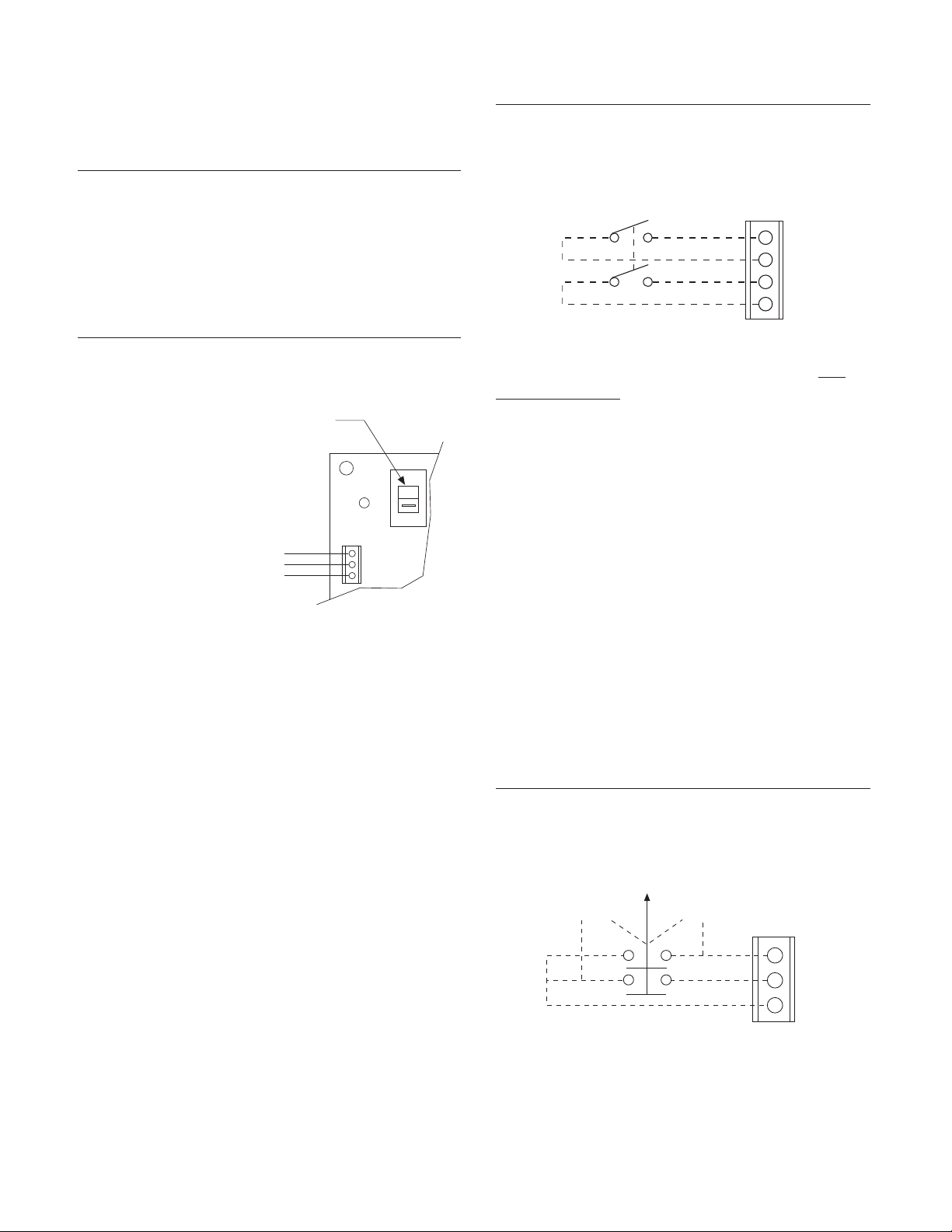
Make sure voltage select
switch is in proper position
Input Power single phase
115 or 230 VAC
The input voltage selector switch must correspond to the voltage of the input power
source.
J4 AC Power Switch and/or Power Indicator
Terminal
J4 provides the terminal connection for an external AC Power Switch and/or power indicator
. The
indicator should not draw more than 40 milliamps
of current. J4 may also be used to supply AC
power to a digital voltmeter by connecting the
meter between J4-2L1 and J4-2L2.
J5 provides the connections for an external
three-position switch with two normally open
contacts. When used in conjunction with a
remote meter, the switch allows the user to
monitor total tension or the tension applied to
either Tensioncell. The meter should be connected to Output #2 at J6, terminals Out2 and Gnd.
With the switch in the normally closed position,
Output #2 will indicate the total tension. In the
Cell#1 position, Output #2 switches to indicate
the tension measured by the W1 Tensioncell.
Changing to the Cell#2 position switches Output
#2 to indicate the tension applied to the W2
Tensioncell.
Terminal Label Description
J5-1 2-Only (Switched) tension W1
J5-2 1-Only (Switched) tension W2
J5-3 Gnd Ground
Note: If an ON-OFF switch is not used,
jumpers must be installed fr
om J4-2L1 to
J4-1L1 and from J4-2L2 to J4-1L2 for
proper operation.
Warner Electric • 800-825-9050 P-2012-2
17
Page 18
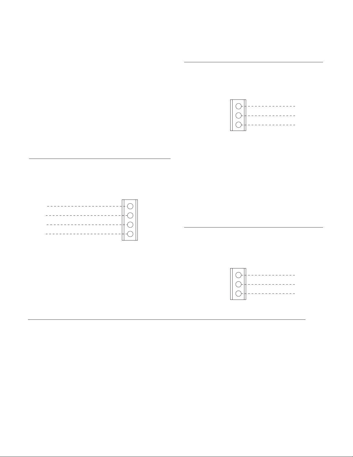
J6 Analog Outputs Terminal
Out 2
Gnd
Out 1
Gnd
J6
Output #2 ( -10 to +10 VDC)
Common
Output #1 ( -10 to + VDC)
Common
1
2
3
4
Normally Closed
Common
Normally Open
J7
NC
COM
NO
1
2
3
Ground
Data Line -
Data Line +
J8
Gnd
Tx-
Tx+
1
2
3
The J6 terminal provides the connections for the
two 10 volt DC outputs. Each output can provide
up to 30 milliamp current.
During setup, each output is individually
scaleable to meet the requirements needed to
calibrate the indicator, drive, or control connected to the board. The board circuitry is designed
to allow a switch to be connected at Terminal J5.
This switch allows the user to monitor the Output
#2 signal with respect to total tension, or the tension applied to either Tensioncell.
The contact may be wired to function in either
the normally open or normally closed state.
Terminal Label Description
J7-1 NC Normally Closed Contact
J7-2
J7-3 NO Normally Open Contact
COM Common
Terminal Label Description
J6-1 Out2 Scaleable -10 to +10 VDC Output
J6-2 Gnd Common
J6-3 Out1 Scaleable -10 to +10 VDC Output
J64 Gnd Common
J7 Threshold Relay Terminal
J7 provides the connections for utilizing the
AC10 Threshold Relay which is a form "C" dry
relay contact, rated at 1 Amp. During setup, the
threshold (percentage of total tension) is programmed to operate when the total tension is
either above or below the threshold value.
J8 RS232 Output Terminal
J8 provides the cable connections for interfacing the PSAC 10 board with a PC to monitor
total tension and tension applied to each
Tensioncell. Data is transferred in ASCII text format.
Terminal Label Description
J8-1 Gnd Ground
J8-2 Tx- Data Line +
J8-3 Tx+ Data Line-
J9 (Spare)
Initial Electrical Checks
Before applying power:
Note: Make sure that the Input Power Selector Switch matches the available input voltage.
Switch 1 2 3 4 5 6 7 8
Position ON ON ON ON OFF ON ON ON
Apply power.
The red Run Mode LED in the lower right hand corner of the board should be flashing.
Warner Electric • 800-825-9050 P-2012-2
18
V
erify that the 8-position dip switch is set as follows:
Page 19

AC10 Setup Procedure
Compression
Te nsion
Important: The input to any external device
wired to J6-3 Out1 or J6-1 Out 2 must be 10
VDC or less.
4. Press ENTER when the desired mode is displayed.
Steps 5 through 8 are performed with only
the tar
e load applied on the Tensioncells.
The following procedure assumes a digital voltmeter will be used when measuring and setting
the desired output voltages. If the outputs are
connected to a digital or analog indicating
device, which will be used during normal operation, these devices may be used during the setup
procedure.
Note: The voltage setting for Output #1 at
100% load must be mor
e positive than the
voltage setting at 0% load. The same
applies to the voltage settings for Output #2.
With power applied to the PSAC10 board, allow
the system to "warmup" for 20 minutes or
longer before proceeding with the setup procedure.
ess and release the SETUP and UP-
1. Pr
ARROW keys simultaneously. An asterisk (*)
will display next to the right tension value.
Note: To exit the SETUP mode at anytime during the following pr
ocedure, press and release
the EXIT key. The system will return to the settings entered during the last completed setup.
5. Apply Load 0%
Insure that the Tensioncells are properly
installed and the material is r
emoved from
the measuring roll.
6. Press ENTER.
0% 0% *0%
2. Press and release SETUP & ENTER simultaneously to start the SETUP pr
ocedure.
Note: The Run Mode LED should stop flashing.
Compression Mode
3. Select either the COMPRESSION MODE or
TENSION MODE using the UP or DOWN
arrow key to toggle between the two choices.
Select the COMPRESSION MODE if the
a.
direction of the tension force is toward the
base block.
b. Select TENSION MODE the direction on
the tension force is away from the base
block.
Warner Electric • 800-825-9050 P-2012-2
19
Page 20
7. Adjust Out 1 0%
Out 2
Gnd
Out 1
Gnd
J6
Output #2 ( -10 to +10 VDC)
Common
Output #1 ( -10 to + VDC)
Common
1
2
3
4
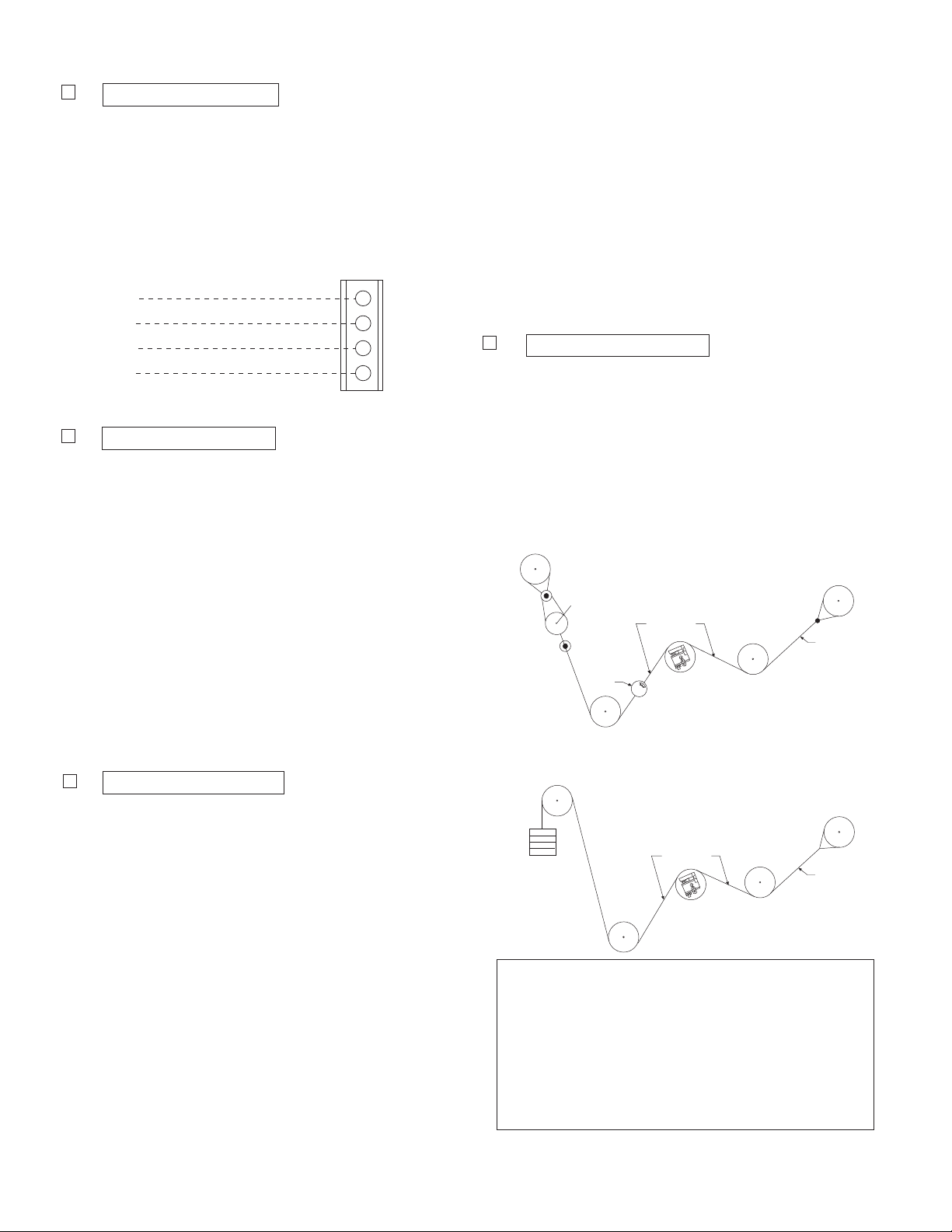
Scale
W eb Path
Roll
Rope
W eb Path
Roll
Rope
W eights for
Max. Tension
a. Connect a digital voltmeter between J6-3
Out 1 and J6-4 Gnd.
Press the UP or DOWN arrow key (and
b.
RAPID key if necessary) until the desired
no load output voltage is attained.
c. Press ENTER.
Note: All rolls used in the pull test
should be free running rolls.
c. With one end of the rope secured, hang a
weight equal to the full load tension. (50%
if selected)
A crane scale may be used to apply the
equired load.
r
d. Press ENTER.
10. Adjust Out 1 100%
a. Connect a digital voltmeter between J6-3
Out 1 and J6-4 Gnd.
8. Adjust Out 2 0%
a. Connect a digital voltmeter between J6-1
Out 2 and J6-2 Gnd.
Press the UP or DOWN arrow key (and
b.
RAPID key if necessary) until the desired
no load output voltage is attained.
c. Press ENTER.
Note: Steps 9 through 12 can be performed
with 50% or 100% load applied when setting
Output #1 and Output #2 voltage. Refer to
the table at the right for minimum r
esultant
load required for setup before proceeding.
9. Apply Load 100%
a. Press the UP or DOWN arrow key to tog-
gle between 50% or 100%. When desir
percentage is displayed.
ed
b. Pr
ess the UP or DOWN arrow key (and
RAPID key if necessary) until the desired
full load output voltage is attained.
c. Press ENTER.
b. Thread a non-stretchable rope over the
Warner Electric • 800-825-9050 P-2012-2
20
The illustrations at the right show two pull
test methods. These tests are used to
apply a load representative of the web
tension. The load should be equal to the
percentage of the full load selected (50%
or 100%).
center of the tension measuring roll simulating the web path.
Model Max Load Min. Tension
Capacity Load for Setup
(Pounds) (Pounds)
ACIDA 60 4
ACIDB 170 10
ACIDC 500 30
Table 2
Page 21

11. Adjust Out 2 100%
5. Press ENTER to select the desired mode.
a. Connect a digital voltmeter between J6-1
Out 2 and J6-2 Gnd.
Press the UP or DOWN arrow key (and
b.
RAPID key if necessary) until the desired
output voltage is attained.
c. Press ENTER.
12. Setup Complete
a. Press ENTER.
Programmable Threshold Relay
The Threshold Relay can be programmed to
Close on Higher (if the total tension goes above)
or Close on Lower (if the total tension goes
below) a preset programmable threshold
between 0% and 102% of the total tension. The
dry relay contact is rated at 1 amp @ 24VDC,
250mA @ 220 VAC, or 500 mA @ 120 VAC.
Note: The threshold may be set while the
web machinery is in operation. Although
the LCD will not be showing the tension,
Output #1, Output #2, and the serial output
will still be r
esponding to tension changes.
If the threshold value or mode is reset with the
equipment operating, the new value will take
fect immediately.
ef
Reset Tare to Zero
The tare value may be zeroed to compensate
for any offsets accumulated during normal operation. Press the SETUP and EXIT keys simultaneously to reset the tare to zero.
Note: Resetting tare to zero must be done
with no tension load applied.
A lamp may be connected between J7-3 NO (or
J7-1 NC) and J7-3 COM during setup, start up,
and/or normal operation to verify the relay is
operating properly.
To set the threshold value:
1. Press the SETUP & RAPID keys simultane-
ously. The display will show a message indicating the current value of the threshold. The
Run Mode LED will continue to flash.
Threshold 000%
2. Press the UP or DOWN arr
ow key until the
desired threshold value is displayed.
3. Press ENTER to select the value.
4. Press the UP or DOWN arrow key to toggle
between the CLOSE ON LOWER or CLOSE
ON HIGHER prompt.
Close on Lower
Warner Electric • 800-825-9050 P-2012-2
21
Page 22

Troubleshooting
Test Points
TP5, TP6, TP7,
TP8, TP9
Enter
J7
J8
J9
LCD Brightness
Adjustment
+5VDC
-5VDC
-5VDC
+5VDC
GND
Test Points
TP2, TP3, TP4
When properly installed in accordance with the
design specification and procedures outlined in
this manual, the AC10 Tension Measuring
System should require little or no regular maintenance or service. Certain conditions, however,
can impair the accuracy, reliability, and performance of the system. The following are some
conditions to consider which may effect the
mechanical and/or electrical components of the
system.
1. Have the system operating parameters
changed?
a. Has the web tension changed?
b. Does the tension plus tare load exceed
the maximum rated load capacity of the
unit?
9. Verify the following voltages.
TP3 to TP7 +10 volts DC
TP4 to TP7 +2.5 volts DC
TP5 to TP7 +15 volts DC
TP6 to TP7 +5volts DC
TP8 to TP7 -5 volts DC
TP9 to TP7 -15 volts DC
10. Are outputs responding to tension changes?
Check connections and voltages at J1, J2,
and J6.
11. Does the output signal(s) from the board
meet the voltage requirements for the
device(s) connected to it?
12. Is the Excitation Voltage to the LVDTs correct?
c. Has the Wrap Angle changed?
2. Are the Tensioncells mounted correctly and
securely?
3. Is the tension measuring roll properly aligned
and does it turn freely?
4. Is the line voltage present and the on-board
Input Power Selector Switch in the correct
position?
5. Is an external power switch connected and
operating correctly? If an external switch is
not used, are the jumpers properly installed
at J4? See page 11.
6. Are all fuses and/or circuit breakers installed
and functional? There are two 250V, 500mA
fuses on the board.
7. Is the Run Mode Indicator LED flashing? If
not, check if the system is in Setup mode.
8. Is the on-board display lit? Check LCD
Brightness Adjustment.
Warner Electric • 800-825-9050 P-2012-2
22
Page 23

a. Using an AC volt meter with at least
5Khz band width, measure the voltage
between J1-3 Exc and J1-4 Exc. The
meter should read 15Vrms ~ 5Khz ±
5%. If excitation voltage is low, turn off
power to the board and remove the J1
connector. Turn power back on and
recheck. If voltage is correct, check for a
short in Tensioncell cable assembly.
Repeat test for Cell #2 at J2.
b. With board power off, remove the J1
connector and measure the resistance
between the Yellow (J1-1 Sig) and Pink
(J1-2 Sig) wire terminals. The resistance
reading should be 335 ohms ± 5%. The
resistance between White (J1-3 Exc) and
Brown (J1-4 Exc) wire terminals should
be 100 ohms ± 5%. If readings are incorrect, disconnect cable at the Tensioncell
designated as Cell #1, and check resistance between pins C and E, and A and
G. Repeat test for Cell #2 at J2.
13. Does the system zero? Press the SETUP
and EXIT keys simultaneously.
14. Does repeating Setup procedure help?
15. If problem(s) persists, contact your local
Warner Electric Representative or the
factory.
Warner Electric • 800-825-9050 P-2012-2
23
Page 24

See Note
3.13
2.13
3.44
1.13
5/8-11 UNC
.93 Full Th’d
for Mounting
Bolt
Electrical
Connector
2.50
.25 Dia. Hole
For Locking
Screw
3.90
1.13
2.00
.75
3.00
Note:Stainless steel self-aligning bushing provided
for 1/2” to 1-1/2” diameter shafts in 1/16” increments.
+
.50
2.00
.25
1.31
1.44
W2 unit shown here.
W1 unit is available.
AC10 Tensioncell Dimensional Drawings
(Specifications and dimensions subject to change without notice.)
Tensioncell Model Number Designation
A C 1 0 B 1 6 W 1
Max.Load Min.Tension
Code Capacity Load for Setup Support Bushing (AC10 only)
(pounds) (pounds) W1 = Split bushing for clamping
A 60 4 W2 = Solid bushing for expansion
B 170 10 S = System, which includes one “W1” cell,
C 500 30 one “W2” cell, two 30 ft cables and a
Examine: AC10B16W1 Shaft Diameter
AC10 = Side Mount Tensioncell
B = 170 pound capacity 16 1
16 = 1 inch shaft diameter 20 1-1/4
W1 = AC10 with split bushing 23 1-7/16
12 3/4
PSAC10 board.
Warner Electric • 800-825-9050 P-2012-2
24
Note: Other shaft diameters are available.
Page 25

PSAC10 Board Dimensions
1.31
.31
.25
5.75
3.13
J3
J4
6.88
6.25
3.13
Mounting
Holes
.250 Dia.
(7) Places
J6
J5
8.25
Warner
Part# PSAC10
Serial#
Setup
Rapid
Exit
Setup
Enter
J7
8.75
J8
J9
J1
J2
Specifications and dimensions subject to change without notice.
Warner Electric • 800-825-9050 P-2012-2
25
Page 26

Warner Electric • 800-825-9050 P-2012-2
26
Page 27

P-2012-3
819-0403
A30 Single Range Tensioncells
Warner Electric • 800-825-9050 P-2012-3
27
Page 28

Description
Damper
C-Flexure
A. General Information
Warner Electric Series 30 Type A Tensioncells
are force transducers, specially designed to
measure and control tension on single strand
wire, cable or filaments, on continuous strip processing lines. They convert the mechanical
force of strand tension into an electrical signal,
which is directly proportional to the strand tension.
Type "A" Tensioncells are installed as single
units with a pulley or sheave (See Figures 1a
and Figure 1b). They are intended for NONROTATING shaft installations. Tensioncells can
be provided to accept shaft sizes from 3/4 inch
to 1-7/16 inch. (See Table 1-B, Page 11)
B. The Mechanical System
The mechanical system consists of a Patented
"C-Flexure Pivot Assembly" which incorporates
a mounting Base Block, frictionless elastic pivot
(or hinge), and Load Plate. (See Figure 2) When
a mechanical force is applied to the Load Plate,
the pivot permits its deflection toward or away
from the Base Block.
For our discussion here, deflection of the Load
Plate toward the Base Block is defined as the
"Compression Mode", while the opposite is
defined as the "Tension Mode". Tensioncells are
designed to operate equally well in either mode.
The Base Block contains an integral Mechanical
Stop to limit the amount of deflection in either
direction, and a Viscous Damper to allow control
of the tensioncell response to rapid changes in
apparent tension loads. (See Figure 2)
W1
Figure 1a Figure 1b
W1
Figure 2
Warner Electric • 800-825-9050 P-2012-3
28
Page 29
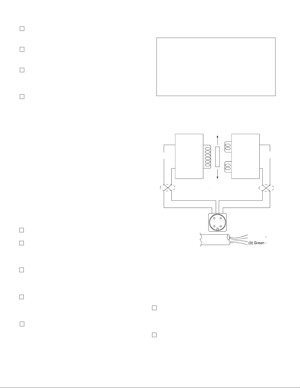
C. The Electrical System
Black - (2)
Red + (1)
Green (3)
Blue (4)
Input
Output
X Twisted Leads
A B
Oscillator Demodulator
P1
S1
S2
X
X
When Supplied
with Cable
(1) Red + DC
(2) Black – DC
(3) Green – Signal
(4) White + Signal
C D
BAC
D
.030
ion
Output vs Deflection
The electrical system consists of a Linear
Variable Differential Transformer (LVDT) which
converts the mechanical deflection of the Load
Plate into a useful electrical output signal. (See
Figure 3) The moveable core of the LVDT is
mechanically coupled to the Load Plate.
This core assemble is factory set and is not
accessible.
D. Type "K" DC LVDT
As illustrated in Figure 3, a DC LVDT consists of
the following components:
• An oscillator network, which converts the DC
input voltage into a high frequency alternating current for exciting the primary coil (P1)
• A Primary Coil (P1)
• A movable, permeable metallic core
• Two Secondary Coils (S1 and S2)
• A demodulator and summing network to rectify and integrate the currents from the
Secondary Coils
With Warner Electric LVDTs, the input and output circuits are electrically isolated from each
other and from the mechanical structure of the
tensioncell. Thus, they may be used in "floating
ground" or "ground return" systems. This eliminates the need for extra circuit boards which are
required for most straingage loadcells.
Tensioncells are factory adjusted to provide an
offset voltage with no load applied (no deflection). Using an input of 24 volts DC, the LVDT is
set to provide an output of 3.5 volts into a resistive load of not less than 100,000 ohms. The
voltage resulting from the maximum rated
deflection then adds to or subtracts from the 3.5
volt offset. This results in an output voltage of
3.5 to 6.5 volts in the Compression Mode and
3.5 to 0.5 volts in the Tension Mode. (See
Figure 4)
While acceptable performance may be obtained
over an input voltage range of 6.0 to 30.0 volts
DC, the output voltage will vary in direct proportion to the input voltage. Because of this, the
use of a well regulated constant voltage power
supply is essential for accurate and repeatable
tension measurement.
Warner Electric • 800-825-9050 P-2012-3
Figure 3
LVDT Output vs. Deflection Chart
Figure 4
29
Page 30

E. Description of Operation
E
D
H
E
RF
N
TW
T
T
The total resultant load per cell (RF) is calculated by resolving all force vectors acting upon the
Tensioncell, with respect to the Loading Line
(OL). (RF) is the resultant of both TENSION and
TARE loads, PER CELL!! (See Figure 5)
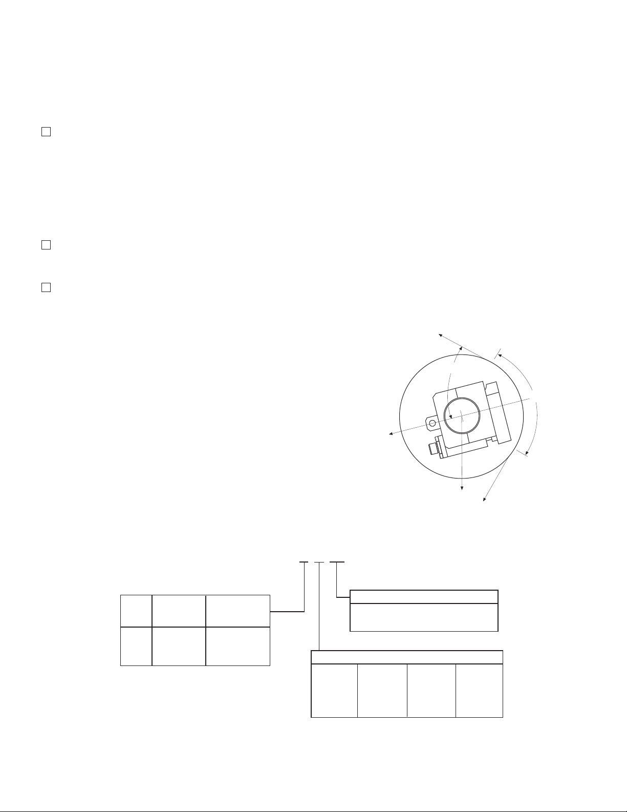
The intrinsic design of Warner Electric
Tensioncells allows the location of the Resultant
Load of Strip Tension (H) on any angle with
respect to the Load Line (OL). Note, however,
that the Total Force vector (RF) must always be
calculated on the line (OL).
Any force vector falling on the line (OR) (through
the pivot point of the C-Flexure) will produce no
deflection, and thus no electrical output.
Rotating the Tensioncell on its mounting bolt
changes the force vectors on the cell. This feature makes it possible to minimize the tare component and maximize the load signal output.
The resultant tare is minimized by mounting the
Tensioncell so that (N) is 31°. (See Figure 6)
Figure 5
Warner Electric • 800-825-9050 P-2012-3
30
Figure 6
Page 31
Installation and Operation
A. Inspection Upon Delivery
Warner Electric tensioncells are carefully packaged in sturdy reinforced cartons or wooden
boxes and are securely blocked or bolted in
place.
1. Upon receipt, examine the exterior of the container for obvious damage or tampering.
2. Check the contents against the packing list.
3. Promptly report any damage or shortage to
both the carrier and Warner Electric.
B. Handling
Tensioncells can be handled manually.
C. Long Term Storage
While Warner Electric loadcells are plated, exposure to weather, dirt, or moisture should be avoided when they are stored.
The locating tab prevents the Tensioncell from
rotating and secures it in a permanent location.
It also provides a means of repeating rotary
position when the Tensioncell needs replacement.
Note: Remove the 1/4" locking screw and
the 5/8" mounting bolt. This permits the r
assembly with Tensioncells to be lifted out
of the machine.
oll
D. Mechanical Installation
Note: Refer to the Dimension Drawing Pages
10 and 11 of this manual for detailed
identification of all parts.
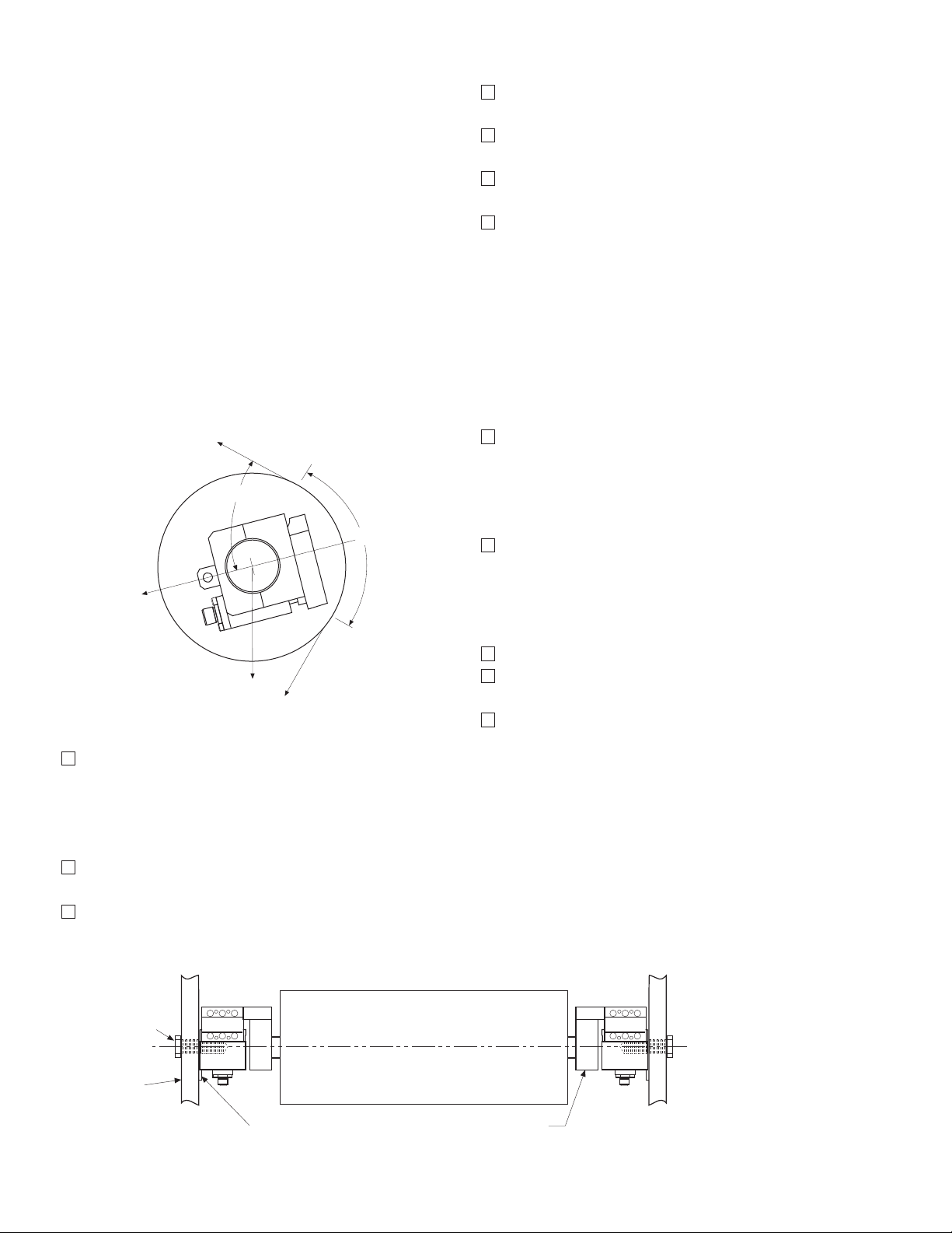
Tensioncells are designated as W1 and W2, one
being the mirr
Warner Electric Wall Mounted Tensioncells are
mounted to the machine frame by a 5/8-11 UNC
bolt which is in line with the centerline of the
measuring roll shaft. This allows the Tensioncell to
be rotated around the centers of the measuring
roll and mounting bolt to achieve the proper
mounting angle. (Description of Operation on
Page 5)
or image of the other. (See Figure 7)
Figure 7
Warner Electric • 800-825-9050 P-2012-3
31
Page 32
To install Tensioncells:
Black - (2)
Red + (1)
Green (3)
Blue (4)
Input
Output
X Twisted Leads
A B
Oscillator Demodulator
P1
S1
S2
X
X
When Supplied
with Cable
(1) Red + DC
(2) Black – DC
(3) Green – Signal
(4) White + Signal
C D
BAC
D
1. Make sure a 5/8” diameter hole is drilled
through the machine frame in line with the
centerline of the measuring roll shaft for the
5/8-11 UNC mounting bolt.
E. Mechanical Alignment
Align the sectional measuring roll to avoid any
mechanical binding or friction. The measuring
roll must be level and perpendicular to the path
of the strip material for accurate measurement.
2. Fasten the Tensioncell to the machine frame
with the mounting bolt.
3. Rotate the Tensioncell to the proper mounting angle and tighten the mounting bolt.
(Refer to Y on the calibration sheet for the
proper mounting angle.)
4. Drill a #6 (.204) hole concentric with the 1/4"
hole in the locating tab.
5. Remove the Tensioncell and tap the hole for
a 1/4-20 thread.
6. Assemble the Tensioncells onto the ends of
the measuring roll shaft.
7. Position the roll with the Tensioncells on the
machine and fasten with the mounting bolts.
8. Rotate the Tensioncells to the proper mounting angle and tighten the mounting bolts.
The Mechanical Stops are fixed for the required
travel of the Load Table.
F. Electrical Installation
(Read the entire electrical wiring procedure
before proceeding.)
1. Turn off all electrical power to the loadcell.
2. Use twisted four conductor signal cable,
Belden 9402 or equivalent, in grounded steel
conduit from the LVDTs to the control panel.
3. Observing correct polarity, connect the positive (+) input lead to Pin A and the negative
(-) input lead to Pin B. (See Figure 8)
4. Connect the positive (+) output lead to Pin D
and the negative (-) output lead to Pin C.
(See Figure 8)
9. Lock the locating pad for each Tensioncell
against the machine frame using the 1/4-20
x 1/2 socket head cap screw.
10. Tighten the shaft in the mounting block on
the W1 unit.
Figure 8
Warner Electric • 800-825-9050 P-2012-3
32
Page 33

Set up and Adjustments Specifications
Roll
Rope
Web Path
Weights for
Type "K" 24 volt DC LVDT Specifications
Input . . . . . . . . . . . . . . . . . . . . . . . . .6-30 volts DC
Output . . .0.5-6.5 volts DC (nominal, open circuit)
Output Impedence . . . . . . . . . . . . . . . .2.5K ohms
Current Consumption . . . . . . . . . . . . . . . . . .40 mA
Recommended Load . . . . . .100K ohms or greater
Max. Operating Temp . . . . . . . . . . . . . . . . . .250°F
Note: Warner Electric loadcells are
calibrated for 24 volt DC input voltage to
ovide a 0.5 to 6.5 volts DC output signal.
pr
Full Load Adjustment
After the loadcell has been zeroed, a pull test
can be made to check the output voltage of the
loadcell at full load.
1. Run a non-stretchable rope over the center
of the tension roll simulating the web path.
(Note: The rolls should be free to turn.)
With one end of the rope secured, hang a
2.
known weight equally over the roll so that
the total tension is equal to the maximum
strip tension specified on the calibration
sheet, at the other end. (See Figure 9)
Electrical Zero Adjustment
(Read the complete Electrical Zero Adjustment
procedure before proceeding with the adjustment.)
1. Disengage strip from the measuring roll so
that no tension force is applied to the loadcell.
2. Connect a voltmeter to Pins C and D. (See
Figure 8)
Apply 24 volt DC electrical power to the
3.
loadcell observing the correct polarity. [Plus
(+) to Pin A and minus (-) to Pin B.] Do not
exceed the maximum rated input voltage.
Note: Allow 20 minutes for the loadcell to
warmup befor
insure accurate readings.
e taking first readings to
3. With a voltmeter connected to Pins C and D
of the connector, an output voltage will be
observed.
Warner Electric Ioadcells instrumentation provides the required signal conditioning and a reliable high level output signal for use as feedback
control of a tension drive system. The feedback
signal is directly proportional to the strip tension
applied. If a Warner Electric control is used,
refer to the control manual for further calibration.
Although the electrical output of Warner Electric
tensioncells are sufficient to drive most electrical
indicators, substantial signal conditioning is normally required for effective tension instrumentation system control. Refer to the documentation
available from the instrumentation supplier for
more information.
4. Measur
e the output voltage of the LVDT
between the Green and Blue leads for each
tensioncell with a volt meter with a sensitivity
of at least 100,000 ohms per volt. The output voltage should be between 0.5 and 6.5
volts.
5. Since Warner Electric Tensioncells cannot be
mechanically zeroed, refer to the Control
Manual for zeroing out the tare weight voltage.
Warner Electric • 800-825-9050 P-2012-3
(Figure 9)
33
Page 34
Trouble Shooting
Black - (2)
Red + (1)
Green (3)
Blue (4)
Input
Output
X Twisted Leads
A B
Oscillator Demodulator
P1
S1
S2
X
X
When Supplied
with Cable
(1) Red + DC
(2) Black – DC
(3) Green – Signal
(4) White + Signal
C D
BAC
D
3. Are LVDTs open or shorted?
When properly installed in accordance with the
original design specifications Warner Electric
tensioncells should require little or no regular
maintenance or service.
Certain conditions, however, can impair their
inherently accurate and reliable performance.
Therefore, if trouble should arise, the following
conditions should be checked.
1. Has the tension measuring system been
changed?
a. An increase or decrease in strip tension.
b. An increase or decrease in the wrap
angle.
If the above parameters have been
changed enough to prevent the unit from
operating within the limits of the fixed
Mechanical Stop, restore parameters to
previous condition or consult factory.
2. Is the loadcell mounted securely?
To check, turn off power and disconnect the
input and output leads. Check coil continuity
and resistance. (Refer to Figure 10)
Figure 10
a Pin A to Pin B (Primary Coil) should be in
excess of 2 megohms.
3. Is tension measuring roll in proper alignment
and does it turn freely?
4. Are bearings and seals free of all binding
and stickiness? Are they worn?
b. Pin A or Pin B to LVDT shell should be in
excess of 5 megohms.
c. Pin C to Pin D (Secondary Coil) should
be approximately 20,000 ohms.
d. Pin C or Pin D to LVDT shell should be in
Electrical
1. Are LVDTs receiving correct input voltage?
Check line voltage, fuses or circuit breakers,
and power switches. Check power supply
If LVDT circuits are open or shorted, replace
LVDT. Contact Warner Electric with tensioncell
model number and serial number.
excess of 5 megohms.
output and voltage to LVDTs.
2. Are all connections secure?
Check for continuity. Retighten all connec-
tions. Recheck operation.
Warner Electric • 800-825-9050 P-2012-3
34
Page 35
Recalibration After Installation
Wall Mounted Tensioncells can be relocated
around the center of the measuring roll. The theory of this operation is explained in the
Description of Operation on Page 5. If this procedure cannot accomplish the necessary
changes because the tension requirements are
extremely different than the original application,
it will be necessary to return the Tensioncells to
the factory for new cells.
Model Number Nomenclature Example
Electrical
Connection
B - MS Connector
Type
A - Pulley or Sheave
Note: For dual load cell applications “W1” and “W2” cell are required.
Series Number (2 Digits)
30 Wall Mount
B A 3 0 T 1 6 K W1
Capacity Range
See Table 1-A
K - DC LVDT with
Maximum 3 VDC
Output Change Including
Tare Displacement
Shaft Diameter
See Table I-B for Type A
Series 30, Type A Specifications – Non-Rotating Shaft Mounting
Series 30, Type A – Nominal Capacity Ranges
Code P T U
Pounds 0-20 0-50 0-90
Example Shown:
BA30T16KW1
B = MS Connector
A = Pulley Mount
30 = Series 30, Wall Mount
T = 0-50 lbs. Capacity
16 = 1” Diameter Shaft
K = K Type DC LVDT
W = Split Bushing
Shaft Mounting
Configuration
W1 Split bushing
W2 Solid bushing
Table I-A
Note: Other load ratings are available as special order .
Contact Warner Electric for other load ranges
available.
Warner Electric • 800-825-9050 P-2012-3
35
Page 36

3.75
for Locking
** Warner Electric wall mounted tensioncells are located by a 5/8-11 bolt at the roll centerline
and locating tab which maintains rotational position to the tensioncell. (See Page 5.)
Shaft Specifications
Code 3/4 1.0
1-1/4
Inches 12 16 20
Table I-B
Note: Other shaft diameters are available as special
. Contact Warner Electric for other shaft
order
diameter availiblilty.
Warner Electric • 800-825-9050 P-2012-3
36
Page 37

P-2012-4
819-0404
B30 Single Range Tensioncells
Warner Electric • 800-825-9050 P-2012-4
37
Page 38

Description
W1
W2
Machine
Frame
B30 Series Tonsioncell
Single Bolt Mounting
Internal
Bearing
Damper
C-Flexure
Far Side
Mechanical Stop
Load
Plate
LVDT
LVDT
Core
General Information
Warner Electric Series 30 Type B Tensioncells
are force transducers especially designed to
measure and control web tension on continuous
strip processing lines. They are normally
installed in matched pairs at each end of a
measuring roll. (See Figure 1)
A Tensioncell consists of a unique combination
of two integral systems (one mechanical, the
other electrical) for converting the mechanical
force of strip tension into an electrical signal
which is directly proportional to the strip tension.
Type "B" Tensioncells are intended for NONROTATING shaft installations. A self-aligning
shaft clamp assures proper alignment of the
measureing roll when the tension cells are bolted to the machine frame. Type "B" Tensioncells
are supplied in matched pairs, one to be mounted at each end of the tension measuring roll.
Note that the cell marked "W2" is a mirror image
of "W1". The 'W2" cell allows for thermal expansion of the shaft. (See Figure 1)
The Mechanical System
The mechanical system consists of a Patented
"C-Flexure Pivot Assembly" which incorporates
a mounting Base Block, frictionless elastic pivot
(or hinge), and Load Plate. (See Figure 2) When
a mechanical force is applied to the Load Plate,
the pivot permits its deflection toward or away
from the Base Block.
Figure 2
38
Type B - Bearings in Roll - Non-Rotating Shaft
Figure 1
Warner Electric • 800-825-9050 P-2012-4
Page 39
For our discussion here, deflection of the Load
DC
Signal
Plate toward the Base Block is defined as the
"Compression Mode", while the opposite is
defined as the "Tension Mode". Tensioncells are
designed to operate equally well in either mode.
The Base Block contains an integral Mechanical
Stop to limit the amount of deflection in either
direction, and a Viscous Damper to allow
control of the tensioncell response to rapid
changes in apparent tension loads. (See Page 3,
Figure 2)
Type "K" DC LVDT
As illustrated in Figure 3, a DC LVDT consists
of the following components:
• An oscillator, which converts the DC input
voltage into a high frequency alternating
current for exciting the primary coil (P1)
• A Primary Coil (P1)
• A movable, permeable metallic core
• Two Secondary Coils (S1 and S2)
The Electrical System
The electrical system consists of a Linear
Variable Differential Transformer (LVDT) which
converts the mechanical deflection of the Load
Plate into a useful electrical output signal. (See
Figure 3.) The movable core of the LVDT is
mechanically coupled to the Load Plate by
means of the Core Adjust Assembly. (See Figure
3) This adjustment is factory set and is not
accessible.
• A demodulator and summing network to
rectify and integrate the currents from the
Secondary Coils
Figure 3
Warner Electric • 800-825-9050 P-2012-4
39
Page 40
7
6
5
4
3
2
1
0
.030” 0.0 .030”
3.5 V. Set Point
Tension
Compression
LVDT Output vs Deflection
O
u
t
p
u
t
V
o
l
t
a
g
e
Deflection
With Warner Electric LVDTs, the input and output circuits are electrically isolated from each
other and from the mechanical structure of the
tensioncell. Thus, they may be used in "floating
ground" or "ground return" systems. This eliminates the need for extra circuit boards which are
required for most straingage loadcells.
Tensioncells are factory adjusted to provide an
offset voltage with no load applied (no deflection). Using an input of 24 volts DC, the LVDT is
set to provide an output of 3.5 volts into a resistive load of not less than 100,000 ohms. The
voltage resulting from the maximum rated
deflection then adds to or subtracts from the 3.5
volt offset. This results in an output voltage of
3.5 to 6.5 volts in the Compression Mode and
3.5 to 0.5 volts in the Tension Mode. (See
Figure 4)
LVDT Output vs. Deflection Chart
Figure 4
While acceptable performance may be obtained
over an input voltage range of 6.0 to 30.0 volts
DC, the output voltage will vary in direct proportion to the input voltage. Because of this, the
use of a well regulated constant voltage power
supply is essential for accurate and repeatable
tension measurement.
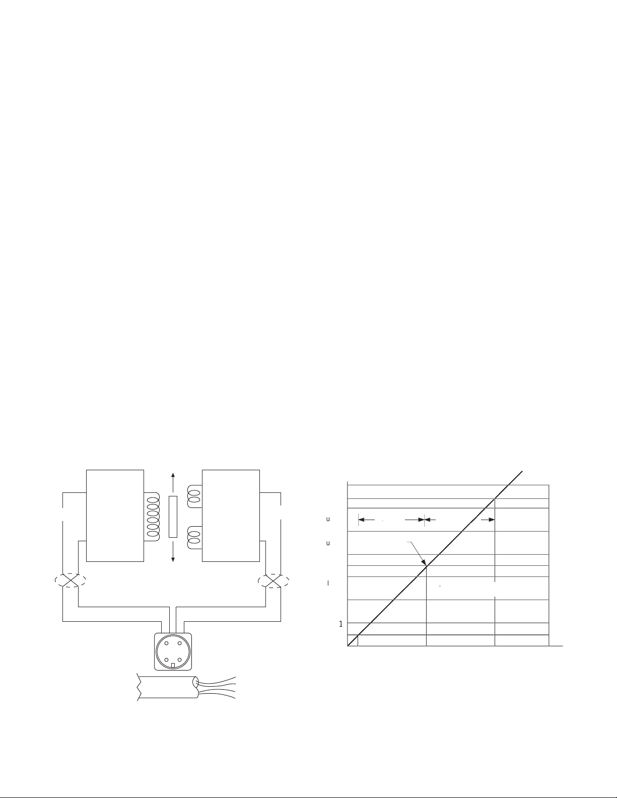
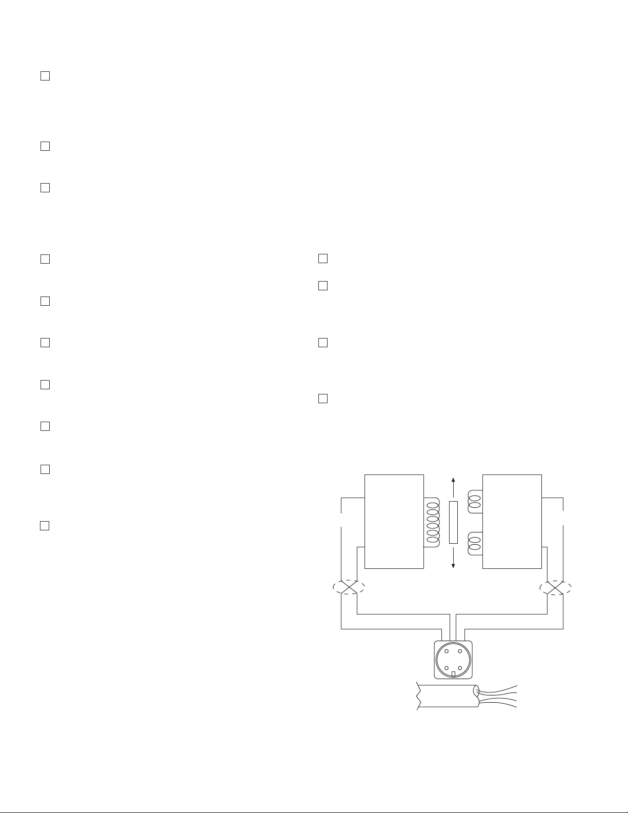
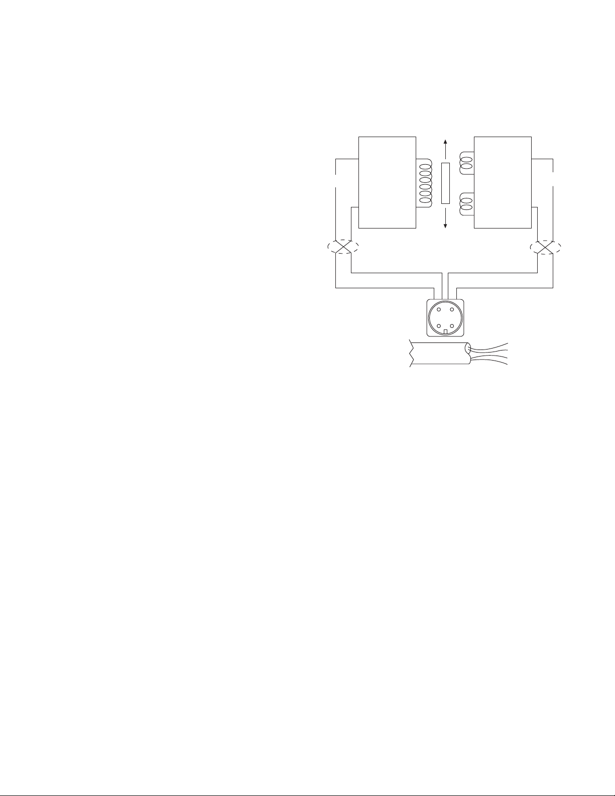
In standard applications, where two Tensioncells
are used, the inputs may be connected in parallel allowing the Tensioncells to be excited from
the same power supply. The LVDT outputs are
then summed to obtain a signal representing the
strip tension and tare loads distributed across
the roll.
Warner Electric • 800-825-9050 P-2012-4
40
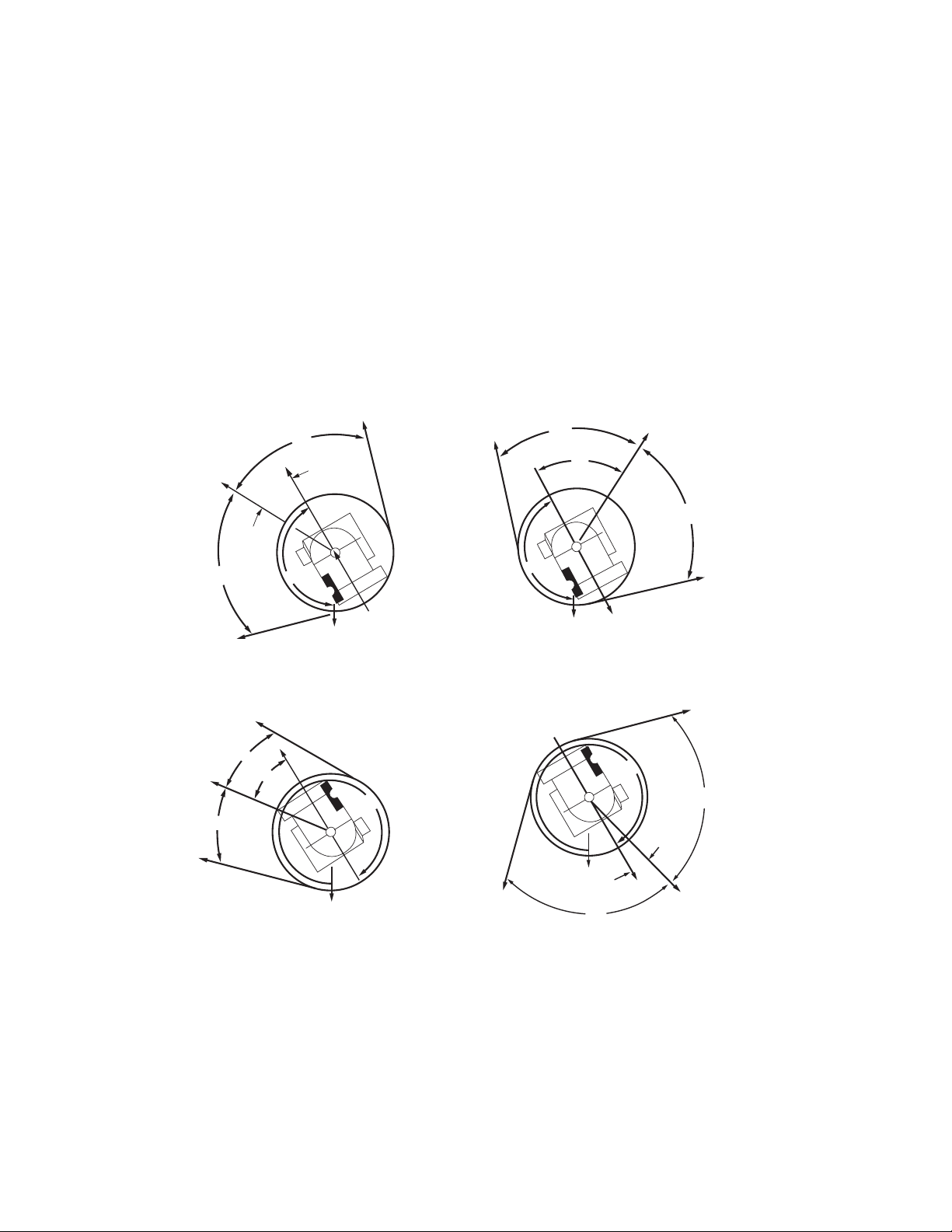
Description of Operation
The total resultant load per cell (RF) is calculated
by resolving all force vectors acting upon the
Tensioncell, with respect to the Loading Line (OL).
(RF) is the resultant of both TENSION and TARE
loads, PER CELL!! (See Figure 5)
(Figure 5)
Page 41
TT
N
TW
D
T
T
H
J
E
E
Figure 6A
Figure 6B
T
T
TW
J
N
D
H
E
E
N
T
T
E
E
H
J
D
TW
Figure 7B
N
TW
E
E
H
T
J
T
D
Figure 7A
The intrinsic design of Warner Electric
Tensioncells allows the location of the Resultant
Load of Strip Tension (H) on any angle with
respect to the Load Line (OL). Note, however,
that the Total Force vector (RF) must always be
calculated on the line (OL).
Any force vector falling on the line (OR) (through
the pivot point of the C-Flexure) will produce no
deflection, and thus no change in electrical output.
Rotating the Tensioncell on its mounting bolt
changes the force vectors on the cell. This feature makes it possible to minimize the tare component and maximize the load signal output.
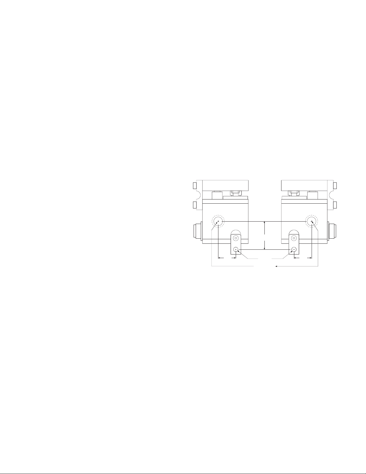
The resultant tare is minimized by mounting the
Tensioncell so that (N) is 149° (See Figures 6A
and 6B) or so that (N) is 329° (See Figures 7A
and 7B).
Warner Electric • 800-825-9050 P-2012-4
41
Page 42

Installation and Operation
Inspection Upon Delivery
Warner Electric Tensioncells are carefully packaged in sturdy reinforced cartons or wooden
boxes and are securely blocked or bolted in
place.
1. Upon receipt, examine the exterior of the
container for obvious damage or tampering.
2. Check the contents against the packing list.
3. Promptly report any damage or shortage to
both the carrier and Warner Electric.
Handling
Tensioncells can be handled manually.
Warner Electric Wall Mounted Tensioncells are
mounted to the machine frame by a 5/8-11 UNC
bolt which is in line with the centerline of the
measuring roll shaft. This allows the Tensioncell
to be rotated around the centers of the measuring roll and mounting bolt to achieve the proper
mounting angle (Description of Operation on
Page 5).
The locating tab prevents the Tensioncell from
rotating and secures it in a permanent location.
It also provides a means of repeating rotary
position when the Tensioncell needs replacement.
Note: Remove the 1/4" locking screw and
the 5/8" mounting bolt. This permits the r
assembly with Tensioncells to be lifted out
of the machine.
oll
Long Term Storage
While Warner Electric loadcells are plated,
exposure to weather, dirt, or moisture should be
avoided when they are stored.
Mechanical Installation
Note: Refer to the Dimension Drawing
Pages 11 and 12 of this manual for detailed
identification of all parts.
Tensioncells are designated as W1 and W2, one
being the mirror image of the other to pr
for mounting between two fixed walls. (See
Figure 8)
ovide
To install Tensioncells:
1. Make sure a 5/8” diameter hole is drilled
through the machine frame in line with the
centerline of the measuring roll shaft for the
5/8-11 UNC mounting bolt.
2. Fasten the Tensioncell to the machine frame
with the mounting bolt.
3. Rotate the Tensioncell to the proper mounting angle and tighten the mounting bolt.
(Refer to N on the calibration sheet for the
proper mounting angle.
4. Drill a #6 (.204) hole concentric with the 1/4"
hole in the locating tab.
5. Remove the Tensioncell and tap the hole for
a 1/4-20 thread.
6. Repeat steps 1 through 5 for the Tensioncell
to be mounted at the other end of the measuring roll.
42
7. Assemble the tensioncells onto the ends of
the measuring roll shaft.
Figure 8
Warner Electric • 800-825-9050 P-2012-4
Page 43
8. Position the roll with the Tensioncells on the
X
DC
Signal
machine and fasten with the mounting bolts.
9. Rotate the Tensioncells to the proper mounting angle and tighten the mounting bolts.
10. Lock the locating pad for each Tensioncell
against the machine frame using the 1/4-20
x 1/2 socket head capscrew.
11. Tighten the shaft in the mounting block on
the W1 unit. (The shaft end at W2 is left free
to allow it to move as the shaft expands with
temperature changes).
Mechanical Alignment
Align the sectional measuring roll to avoid any
mechanical binding or friction. The measuring
roll must be level and perpendicular to the path
of the strip material for accurate measurement.
Specifications
Type "K" 24 volt DC LVDT Specifications
Input . . . . . . . . . . . . . . . . . . . . . . . . .6-30 volts DC
Output . . .0.5-6.5 volts DC (nominal, open circuit)
Output Impedence . . . . . . . . . . . . . . . .2.5K ohms
Current Consumption . . . . . . . . . . . . . . . . .40 mA
Recommended Load . . . . .100K ohms or greater
Max. Operating Temp . . . . . . . . . . . . . . . . . .250°F
Note: Warner Electric loadcells are
calibrated for 24 volt DC input voltage to
ovide a 0.5 to 6.5 volts DC output signal.
pr
The Mechanical Stops are fixed for the required
travel of the Load Table.
Electrical Installation
(Read the entire electrical wiring procedure
before proceeding.)
1. Turn off all electrical power to the loadcell.
2. Use twisted four conductor signal cable,
Belden 9402 or equivalent, in grounded steel
conduit from the LVDTs to the control panel.
3. Observing correct polarity, connect the positive (+) input lead to Pin A and the negative
(-) input lead to Pin B. (See Figure 9)
4. Connect the positive (+) output lead to Pin D
and the negative (-) output lead to Pin C.
(See Figure 9)
5. Repeat Steps 1 through 4 of the electrical
wiring procedure for the Tensioncells mounted on the other end of the measuring roll.
Figure 9
Electrical Zero Adjustment
(Read the complete Electrical Zero Adjustment
procedure before proceeding with the adjustment.)
1. Disengage strip from the measuring roll so
that no tension force is applied to the loadcell.
2. Connect a voltmeter to Pins C and D (See
Figure 9)
Warner Electric • 800-825-9050 P-2012-4
43
Page 44

3. Apply 24 volt DC electrical power to the
loadcell observing the correct polarity. [Plus
(+) to Pin A and minus (-) to Pin B.] Do not
exceed the maximum rated input voltage.
Note: Allow 20 minutes for the loadcell to
warmup befor
e taking first readings to
insure accurate readings.
4. Measure the output voltage of the LVDT
between the Gr
een and White leads for each
tensioncell with a volt meter with a sensitivity of at least 100,000 ohms per volt. The
output voltage should be between 0.5 and
6.5 volts.
5. Since Warner Electric Tensioncells cannot be
mechanically zeroed, refer to the Control
Manual for zeroing out the tare weight voltage.
Full Load Adjustment
After the loadcell has been zeroed, a pull test
can be made to check the output voltage of the
loadcell at full load. (See calibration sheet for
voltage output.)
1. Run a non-stretchable rope over the center
of the tension roll simulating the web path.
(Note: The rolls should be free to turn.)
3. With a voltmeter connected to Pins C and D
of the connector, an output voltage will be
observed.
4. Repeat Step 3 for the Tensioncell mounted
on the opposite end of the measuring roll.
Warner Electric Ioadcells instrumentation provides the required signal conditioning and a reliable high level output signal for use as feedback
control of a tension drive system. The feedback
signal is directly proportional to the strip tension
applied. If a Warner Electric control is used,
refer to the control manual for further calibration.
Although the electrical output of Warner Electric
tensioncells are sufficient to drive most electrical
indicators, substantial signal conditioning is normally required for effective tension instrumentation system control. Refer to the documentation
available from the instrumentation supplier for
more information.
Trouble Shooting
When properly installed in accordance with the
original design specifications Warner Electric
tensioncells should require little or no regular
maintenance or service.
2. With one end of the r
ope secured, hang a
known weight equally over the roll so that
the total tension is equal to the maximum
strip tension specified on the calibration
sheet, at the other end. (See Figure 10)
Warner Electric • 800-825-9050 P-2012-4
44
Figure 10
Certain conditions, however, can impair their
inherently accurate and reliable performance.
Therefore, if trouble should arise, the following
conditions should be checked. (Continued on
next page)
Page 45

Mechanical
X
DC
Signal
1. Has the tension measuring system been
changed?
a. An increase or decrease in strip tension
(Refer to A on the calibration sheet for
specified strip tension.)
b. An increase or decrease in the wrap
angle. (Refer to B on the calibration sheet
for the specified wrap angle.)
If the above parameters have been changed
enough to prevent the unit from operating within
the limits of the fixed. Mechanical Stops, replacement of the tensioncells required. For this modification, the Tensioncell should be returned to the
factory with complete specifications.
2. Are the loadcells mounted securely?
c. Pin C to Pin D (Secondary Coil) should
be approximately 20,000 ohms.
d. Pin C or Pin D to LVDT shell should be in
excess of 5 megohms.
If LVDT circuits are open or shorted, replace the
Tensioncell LVDT. Contact Warner Electric with
Tensioncell model number and serial number.
Recalibration after Installation
Wall Mounted Tensioncells can be relocated
around the center of the measuring roll. The
theory of this operation is explained in the
Description of Operation on Page 5. If this procedure cannot accomplish the necessary
changes because the tension requirements are
extremely different than the original application,
it will be necessary to return the Tensioncells to
the factory for a different Tensioncell.
3. Is tension measuring roll in proper alignment
and does it turn freely?
4. Are bearings and seals free of all binding and
stickiness? Are they worn?
Electrical
1. Are LVDTs receiving correct input voltage?
Check line voltage, fuses or circuit breakers,
and power switches. Check power supply
output and voltage to LVDTs.
2. Are all connections secure?
Check for continuity. Retighten all connec-
tions. Recheck operation.
3. Are LVDTs open or shorted?
To check, turn off power and disconnect the
input and output leads. Check coil continuity and
resistance. (Refer to Figure 11)
a. Pin A to Pin B (Primary Coil) should be in
excess of 2 megohms.
Figure 11
b. Pin A or Pin B to LVDT shell should be in
excess of 5 megohms.
Warner Electric • 800-825-9050 P-2012-4
45
Page 46

Model Number Nomenclature Example
Electrical
Connection
B - MS Connector
Type
B - Non-Rotating Shaft
Series 30, Type B Specifications – Non-Rotating Shaft Mounting
Series Number (2 Digits)
30 Wall Mount
B B 3 0 P 1 6 K W1
Capacity Range
See Table II-A
K - DC LVDT with
Maximum 3 VDC Output
Change Including Tare
Displacement
Shaft Diameter
Shaft Mounting Configuration
W1-Split bushing
W2-Solid bushing
Example Shown:
BC30P16KW1
N = MS Connector
C = Rotating Shaft
30 = Series 30, Wall Mount
P = 0-20 lbs. Capacity
16 = 1” Diameter Shaft
K = K Type DC LVDT
W1 = Split Bushing
See Table ll-B
Series 30, Type B – Nominal Capacity Ranges
Code P T U X Z
Pounds 0-20 0-50 0-90 0-200 0-500
Table II-A
Note: Other Load ranges are available on special order. Contact Warner Electric for ratings & abalability.
Warner Electric • 800-825-9050 P-2012-4
46
Page 47

3.75
2.88
3.63
2.31
RH
2.44
1.56
1.63
1.06
1.82
3.13
.94
**Warner Electric wall mounted tensioncells are located by a 5/8-11 bolt at the roll centerline and locating tab which
maintains rotational position of the tensioncell. (See Page 6.)
Notes:
W1 unit shown here.
W2 unit is applied at the opposite end of the r
oll.
W1 unit clamps the shaft while W2 allows for
temperature expansion of the roll.
Both units have self-aligning feature.
Series 30, Type B Shaft Diameter Code
Code 12 16 20 23
Inches 3/4 1.0 1-1/4 1-7/16
RH 1.00 1.13
Table II-B
Note: Other shaft diameters are availible in special order.
Contact Warner Electric for other shaft diameter avalibility.
Warner Electric • 800-825-9050 P-2012-4
47
Page 48

Warner Electric • 800-825-9050 P-2012-4
48
Page 49

P-2012-5
819-0405
C30 Single Range Tensioncells
Warner Electric • 800-825-9050 P-2012-5
49
Page 50
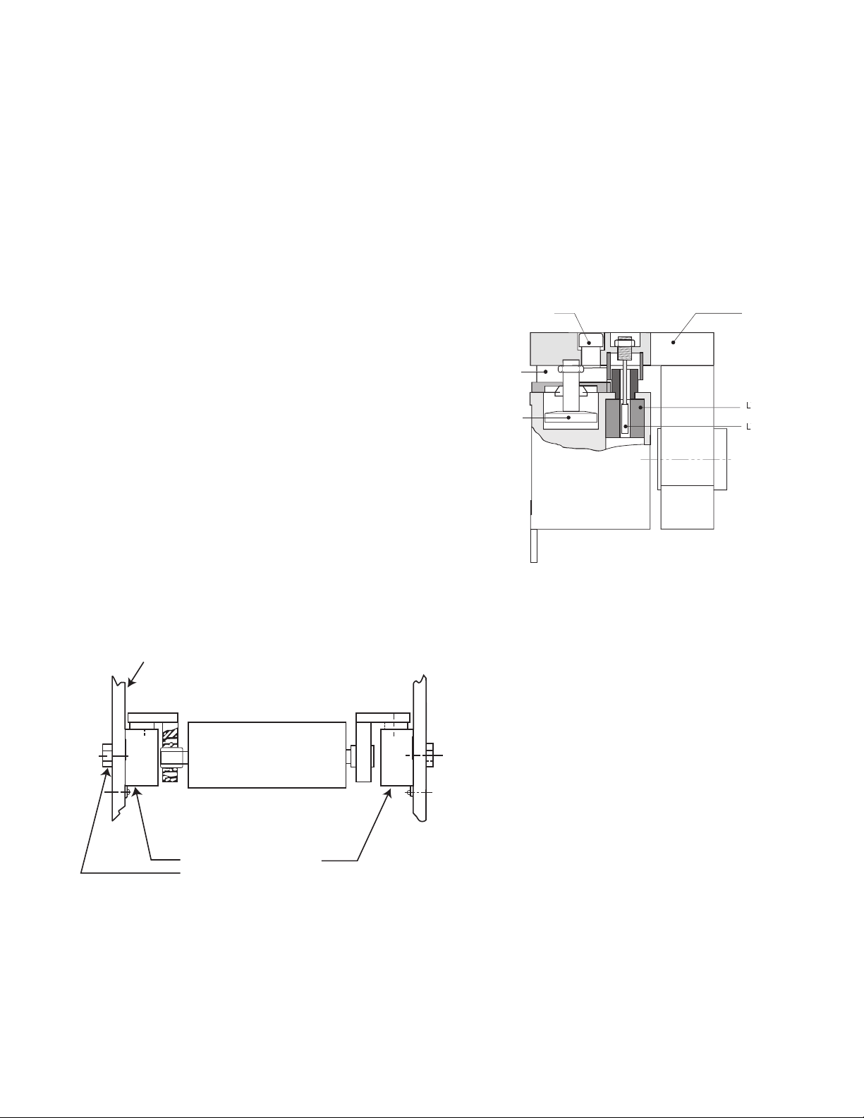
Description
W1 W2
Machine
Frame
C30 Series Tensioncell
Single Bolt Mounting
General Information
Warner Electric Series 30 Type C Tensioncells
are force transducers especially designed to
measure and control web tension on continuous
strip processing lines. They are normally
installed in matched pairs at each end of a
measuring roll. (See Figure 1)
A Tensioncell consists of a unique combination
of two integral systems (one mechanical, the
other electrical) for converting the mechanical
force of strip tension into an electrical signal
which is directly proportional to the strip tension.
Type "C" Tensioncells are intended for ROTATING shaft installations. They are supplied with
self-aligning ball bearings to assure positive
alignment of the measuring roll. Type "C"
Tensioncells are supplied in matched pairs, one
to be mounted at each end of the tension measuring roll. Note that the cell marked "W2" is a
mirror image of "W1". The 'W2" cell allows for
thermal expansion of the rotating shaft. (See
Figure 1)
The Mechanical System
The mechanical system consists of a Patented
"C-Flexure Pivot Assembly" which incorporates
a mounting Base Block, frictionless elastic pivot
(or hinge), and Load Plate. (See Figure 2) When
a mechanical force is applied to the Load Plate,
the pivot permits its deflection toward or away
from the Base Block.
Figure 2
Self-Aligning Bearings in Tensioncell - Rotating Shaft
Figure 1
Warner Electric • 800-825-9050 P-2012-5
50
Page 51

For our discussion here, deflection of the Load
X
DC
Signal
Plate toward the Base Block is defined as the
"Compression Mode", while the opposite is
defined as the "Tension Mode". Tensioncells are
designed to operate equally well in either mode.
The Base Block contains an integral Mechanical
Stop to limit the amount of deflection in either
direction, and a Viscous Damper to allow
control of the tensioncell response to rapid
changes in apparent tension loads. (See Page 3,
Figure 2)
The Electrical System
The electrical system consists of a Linear
Variable Differential Transformer (LVDT) which
converts the mechanical deflection of the Load
Plate into a useful electrical output signal. (See
Figure 2) The movable core of the LVDT is
mechanically coupled to the Load Plate by
means of the Core Adjust Assembly. (See Figure
3) This adjustment is factory set and is not
accessible.
Type "K" DC LVDT
As illustrated in Figure 4, a DC LVDT consists
of the following components:
• An oscillator network, which converts the
DC input voltage into a high frequency alternating current for exciting the primary coil
(P1).
• A Primary Coil (P1)
• A movable, permeable metallic core
• Two Secondary Coils (S1 and S2)
• A demodulator and summing network to
rectify and integrate the currents from the
Secondary Coils
Figure 3
Warner Electric • 800-825-9050 P-2012-5
51
Page 52
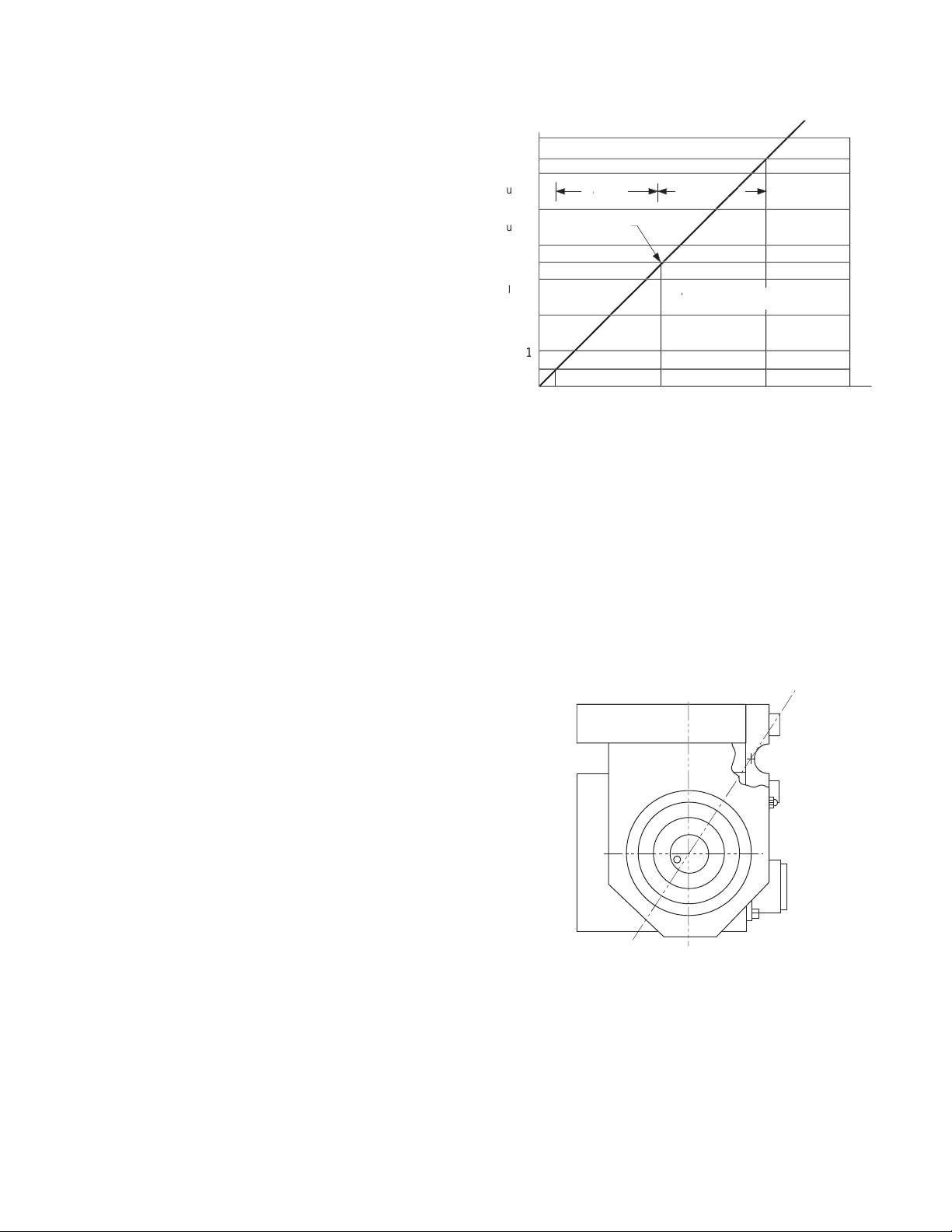
.030
io
Output vs Deflection
With Warner Electric LVDTs, the input and output circuits are electrically isolated from each
other and from the mechanical structure of the
tensioncell. Thus, they may be used in "floating
ground" or "ground return" systems. This eliminates the need for extra circuit boards which are
required for most straingage loadcells.
Tensioncells are factory adjusted to provide an
offset voltage with no load applied (no deflection). Using an input of 24 volts DC, the LVDT is
set to provide an output of 3.5 volts into a resistive load of not less than 100,000 ohms. The
voltage resulting from the maximum rated
deflection then adds to or subtracts from the 3.5
volt offset. This results in an output voltage of
3.5 to 6.5 volts in the Compression Mode and
3.5 to 0.5 volts in the Tension Mode. (See
Figure 4)
LVDT Output vs. Deflection Chart
Figure 4
While acceptable performance may be obtained
over an input voltage range of 6.0 to 30.0 volts
DC, the output voltage will vary in direct proportion to the input voltage. Because of this, the
use of a well regulated constant voltage power
supply is essential for accurate and repeatable
tension measurement.
In standard applications, where two Tensioncells
are used, the inputs may be connected in parallel allowing the Tensioncells to be excited from
the same power supply. The LVDT outputs are
then summed to obtain a signal representing the
strip tension and tare loads distributed across
the roll.
Description of Operation
The total resultant load per cell (RF) is calculated
by resolving all force vectors acting upon the
Tensioncell, with respect to the Loading Line (OL).
(RF) is the resultant of both TENSION and TARE
loads, PER CELL!! (See Figure 5)
Warner Electric • 800-825-9050 P-2012-5
52
(Figure 5)
Page 53

TT
N
TW
D
T
T
H
J
E
E
Figure 6A
Figure 6B
T
T
TW
J
N
D
H
E
E
N
T
T
E
E
H
J
D
TW
Figure 7B
N
TW
E
E
H
T
J
T
D
Figure 7A
The intrinsic design of Warner Electric
Tensioncells allows the location of the Resultant
Load of Strip Tension (H) on any angle with
respect to the Load Line (OL). Note, however,
that the Total Force vector (RF) must always be
calculated on the line (OL).
Any force vector falling on the line (OR) (through
the pivot point of the C-Flexure) will produce no
deflection, and thus no change in electrical output.
Rotating the Tensioncell on its mounting bolt
changes the force vectors on the cell. This feature makes it possible to minimize the tare component and maximize the load signal output.
The resultant tare is minimized by mounting the
Tensioncell so that (N) is 149° (See Figures 6A
and 6B) or so that (N) is 329° (See Figures 7A
and 7B).
Warner Electric • 800-825-9050 P-2012-5
53
Page 54

Installation and Operation
Inspection Upon Delivery
Warner Electric Tensioncells are carefully packaged in sturdy reinforced cartons or wooden
boxes and are securely blocked or bolted in
place.
1. Upon receipt, examine the exterior of the
container for obvious damage or tampering.
2. Check the contents against the packing list.
3. Promptly report any damage or shortage to
both the carrier and Warner Electric.
Handling
Tensioncells can be handled manually.
Warner Electric Wall Mounted Tensioncells are
mounted to the machine frame by a 5/8-11 UNC
bolt which is in line with the centerline of the
measuring roll shaft. This allows the Tensioncell
to be rotated around the centers of the measuring roll and mounting bolt to achieve the proper
mounting angle (Description of Operation on
Page 6).
The locating tab prevents the Tensioncell from
rotating and secures it in a permanent location.
It also provides a means of repeating rotary
position when the Tensioncell needs replacement.
Note: Remove the 1/4" locking screw and
the 5/8" mounting bolt. This permits the r
assembly with Tensioncells to be lifted out
of the machine.
oll
Long Term Storage
While Warner Electric loadcells are plated,
exposure to weather, dirt, or moisture should be
avoided when they are stored.
Mechanical Installation
Note: Refer to the Dimension Drawing
Pages 11 and 12 of this manual for detailed
identification of all parts.
Tensioncells are designated as W1 and W2, one
being the mirror image of the other to pr
for mounting between two fixed walls. (See
Figure 8)
ovide
To install Tensioncells:
1. Make sure a 5/8” diameter hole is drilled
through the machine frame in line with the
centerline of the measuring roll shaft for the
5/8-11 UNC mounting bolt.
2. Fasten the Tensioncell to the machine
frame with the mounting bolt.
3. Rotate the Tensioncell to the proper
mounting angle and tighten the mounting
bolt. (Refer to N on the calibration sheet for
the proper mounting angle.
4. Drill a #6 (.204) hole concentric with the
1/4" hole in the locating tab.
5. Remove the Tensioncell and tap the hole
for a 1/4-20 thread.
6. Repeat steps 1 through 5 for the
Tensioncell to be mounted at the other end
of the measuring roll.
54
7. Assemble the tensioncells onto the ends of
the measuring roll shaft.
Figure 8
Warner Electric • 800-825-9050 P-2012-5
Page 55
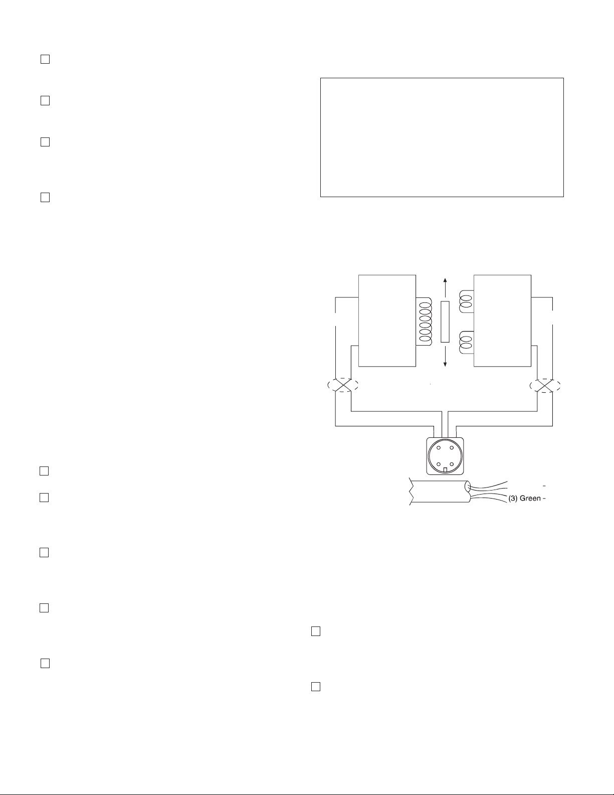
8. Position the roll with the Tensioncells on the
X
DC
Signal
machine and fasten with the mounting bolts.
9. Rotate the Tensioncells to the proper mounting angle and tighten the mounting bolts.
10. Lock the locating pad for each Tensioncell
against the machine frame using the 1/4-20
x 1/2 socket head capscrew.
11. Tighten the shaft in the mounting block on
the W1 unit. (The shaft end at W2 is left free
to allow it to move as the shaft expands with
temperature changes).
Mechanical Alignment
Align the sectional measuring roll to avoid any
mechanical binding or friction. The measuring
roll must be level and perpendicular to the path
of the strip material for accurate measurement.
Specifications
Type "K" 24 volt DC LVDT Specifications
Input . . . . . . . . . . . . . . . . . . . . . . . . .6-30 volts DC
Output . . .0.5-6.5 volts DC (nominal, open circuit)
Output Impedence . . . . . . . . . . . . . . . .2.5K ohms
Current Consumption . . . . . . . . . . . . . . . . .40 mA
Recommended Load . . . . .100K ohms or greater
Max. Operating Temp . . . . . . . . . . . . . . . . . .250°F
Note: Warner Electric loadcells are
calibrated for 24 volt DC input voltage to
ovide a 0.5 to 6.5 volts DC output signal.
pr
The Mechanical Stops are fixed for the required
travel of the Load Table.
Electrical Installation
(Read the entire electrical wiring procedure
before proceeding.)
1. Turn off all electrical power to the loadcell.
2. Use twisted four conductor signal cable,
Belden 9402 or equivalent, in grounded steel
conduit from the LVDTs to the control panel.
3. Observing correct polarity, connect the posi-
tive (+) input lead to Pin A and the negative
(-) input lead to Pin B. (See Figure 9)
4. Connect the positive (+) output lead to Pin D
and the negative (-) output lead to Pin C.
(See Figure 9)
5. Repeat Steps 1 through 4 of the electrical
wiring procedure for the Tensioncells mounted on the other end of the measuring roll.
Figure 9
Electrical Zero Adjustment
(Read the complete Electrical Zero Adjustment
procedure before proceeding with the adjustment.)
1. Disengage strip from the measuring roll so
that no tension force is applied to the loadcell.
2. Connect a voltmeter to Pins C and D (See
Figure 9)
Warner Electric • 800-825-9050 P-2012-5
55
Page 56

3. Apply 24 volt DC electrical power to the
T
loadcell observing the correct polarity. [Plus
(+) to Pin A and minus (-) to Pin B.] Do not
exceed the maximum rated input voltage.
Note: Allow 20 minutes for the loadcell to
warmup befor
e taking first readings to
insure accurate readings.
4. Measure the output voltage of the LVDT
between the Gr
een and Blue leads for each
tensioncell with a volt meter with a sensitivity
of at least 100,000 ohms per volt. The output voltage should be between 0.5 and 6.5
volts.
5. Since Warner Electric Tensioncells cannot be
mechanically zeroed, refer to the Control
Manual for zeroing out the tare weight voltage.
Full Load Adjustment
After the loadcell has been zeroed, a pull test
can be made to check the output voltage of the
loadcell at full load. (See calibration sheet for
voltage output.)
1. Run a non-stretchable rope over the center
of the tension roll simulating the web path.
(Note: The rolls should be free to turn.)
3. With a voltmeter connected to Pins C and D
of the connector, an output voltage will be
observed.
4. Repeat Step 3 for the Tensioncell mounted
on the opposite end of the measuring roll.
Warner Electric Ioadcells instrumentation provides the required signal conditioning and a reliable high level output signal for use as feedback
control of a tension drive system. The feedback
signal is directly proportional to the strip tension
applied. If a Warner Electric control is used,
refer to the control manual for further calibration.
Although the electrical output of Warner Electric
tensioncells are sufficient to drive most electrical
indicators, substantial signal conditioning is normally required for effective tension instrumentation system control. Refer to the documentation
available from the instrumentation supplier for
more information.
Trouble Shooting
When properly installed in accordance with the
original design specifications Warner Electric
tensioncells should require little or no regular
maintenance or service.
2. With one end of the r
ope secured, hang a
known weight equally over the roll so that
the total tension is equal to the maximum
strip tension specified on the calibration
sheet, at the other end. (See Figure 10)
Warner Electric • 800-825-9050 P-2012-5
56
Figure 10
Certain conditions, however, can impair their
inherently accurate and reliable performance.
Therefore, if trouble should arise, the following
conditions should be checked. (Continued on
next page)
Page 57

Mechanical
X
DC
Signal
1. Has the tension measuring system been
changed?
a. An increase or decrease in strip tension
(Refer to A on the calibration sheet for
specified strip tension.)
b. An increase or decrease in the wrap
angle. (Refer to B on the calibration sheet
for the specified wrap angle.)
If the above parameters have been changed
enough to prevent the unit from operating within
the limits of the fixed. Mechanical Stops, replacement of the tensioncells required. For this modification, the Tensioncell should be returned to the
factory with complete specifications.
2. Are the loadcells mounted securely?
c. Pin C to Pin D (Secondary Coil) should
be approximately 20,000 ohms.
d. Pin C or Pin D to LVDT shell should be in
excess of 5 megohms.
If LVDT circuits are open or shorted, replace the
Tensioncell LVDT. Contact Warner Electric with
Tensioncell model number and serial number.
Recalibration after Installation
Wall Mounted Tensioncells can be relocated
around the center of the measuring roll. The
theory of this operation is explained in the
Description of Operation on Page 5. If this procedure cannot accomplish the necessary
changes because the tension requirements are
extremely different than the original application,
it will be necessary to return the Tensioncells to
the factory for a different Tensioncell.
3. Is tension measuring roll in proper alignment
and does it turn freely?
4. Are bearings and seals free of all binding and
stickiness? Are they worn?
Electrical
1. Are LVDTs receiving correct input voltage?
Check line voltage, fuses or circuit breakers,
and power switches. Check power supply
output and voltage to LVDTs.
2. Are all connections secure?
Check for continuity. Retighten all connec-
tions. Recheck operation.
3. Are LVDTs open or shorted?
To check, turn off power and disconnect the
input and output leads. Check coil continuity and
resistance. (Refer to Figure 11)
a. Pin A to Pin B (Primary Coil) should be in
excess of 2 megohms.
Figure 11
b. Pin A or Pin B to LVDT shell should be in
excess of 5 megohms.
Warner Electric • 800-825-9050 P-2012-5
57
Page 58
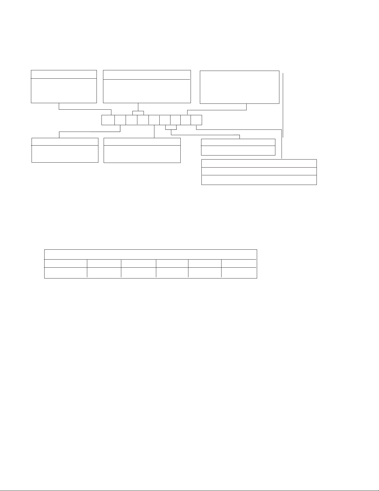
Model Number Nomenclature Example
Electrical
Series Number (2 Digits)
Connection
B - MS Connector
30 Wall Mount
B C 3 0 P 1 6 K W1
Type
C - Rotating Shaft
Capacity Range
See Table II-A
Series 30, Type C Specifications – Rotating Shaft Mounting
K - DC LVDT with
Maximum 3 VDC Output
Change Including Tare
Displacement
Shaft Diameter
See Table ll-B
Shaft Mounting Configuration
W1-Split bushing
W2-Solid bushing
Example Shown:
BC30P16KW1
N = MS Connector
C = Rotating Shaft
30 = Series 30, Wall Mount
P = 0-20 lbs. Capacity
16 = 1” Diameter Shaft
K = K Type DC LVDT
W1 = Split Bushing
Series 30, Type C – Nominal Capacity Ranges
Code P T U X Z
Pounds 0-20 0-50 0-90 0-200 0-500
Table II-A
Note: Other load ratings are available as special order.
Contact Warner Electric for ratings and availability.
Warner Electric • 800-825-9050 P-2012-5
58
Page 59
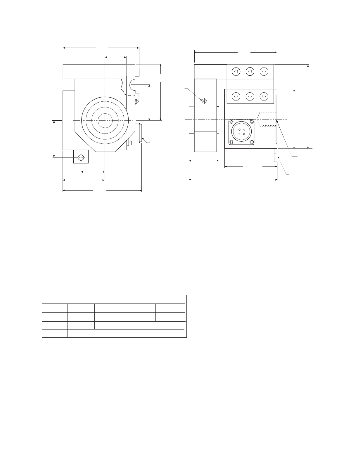
for Locking
**Warner wall mounted tensioncells are located by a 5/8-11 bolt at the roll centerline and locating tab which
maintains rotational position of the tensioncell. (See Page 6.)
Notes:
W1 unit shown here.
W2 unit is applied at the opposite end of the roll.
W1 unit clamps the shaft while W2 allows for
temperature expansion of the roll.
Both units have self-aligning feature.
Series 30, Type C Shaft Diameter Code
Code 12 16 20 23
Inches 3/4 1.0 1-1/4 1-7/16
RH 1.31 1.38 1.69
RT 3.81 4.131.00 | 1.13
Table II-B
Note: Other shaft diamters are available as special order. Contact Warner
Electric for ratings and availability.
Warner Electric • 800-825-9050 P-2012-5
59
Page 60

Warranty
Warner Electric LLC warrants that it will repair or replace (whichever it deems advisable) any
product manufactured and sold by it which proves to be defective in material or workmanship
within a period of one (1) year from the date of original purchase for consumer, commercial or
industrial use.
This warranty extends only to the original purchaser and is not transferable or assignable without
Warner Electric LLC’s prior consent.
Warranty service can be obtained in the U.S.A. by returning any defective product, transportation
charges prepaid, to the appropriate Warner Electric LLC factory. Additional warranty information
may be obtained by writing the Customer Satisfaction Department, Warner Electric LLC, 449
Gardner Street, South Beloit, Illinois 61080, or by calling 815-389-3771.
A purchase receipt or other proof of original purchase will be required before warranty service is
rendered. If found defective under the terms of this warranty, repair or replacement will be made,
without charge, together with a refund for transportation costs. If found not to be defective, you
will be notied and, with your consent, the item will be repaired or replaced and returned to you
at your expense.
This warranty covers normal use and does not cover damage or defect which results from
alteration, accident, neglect, or improper installation, operation, or maintenance.
Some states do not allow limitation on how long an implied warranty lasts, so the above limitation
may not apply to you.
Warner Electric LLC’s obligation under this warranty is limited to the repair or replacement of the
defective product and in no event shall Warner Electric LLC be liable for consequential, indirect,
or incidental damages of any kind incurred by reason of the manufacture, sale or use of any
defective product. Warner Electric LLC neither assumes nor authorizes any other person to give
any other warranty or to assume any other obligation or liability on its behalf.
WITH RESPECT TO CONSUMER USE OF THE PRODUCT, ANY IMPLIED WARRANTIES WHICH
THE CONSUMER MAY HAVE ARE LIMITED IN DURATION TO ONE YEAR FROM THE DATE OF
ORIGINAL CONSUMER PURCHASE. WITH RESPECT TO COMMERCIAL AND INDUSTRIAL
USES OF THE PRODUCT, THE FOREGOING WARRANTY IS IN LIEU OF AND EXCLUDES ALL
OTHER WARRANTIES, WHETHER EXPRESSED OR IMPLIED BY OPERATION OF LAW OR
OTHERWISE, INCLUDING, BUT NOT LIMITED TO, ANY IMPLIED WARRANTIES OF
MERCHANTABILITY OR FITNESS.
Some states do not allow the exclusion or limitation of incidental or consequential damages, so
the above limitation or exclusion may not apply to you. This warranty gives you specic legal
rights and you may also have other rights which vary from state to state.
Changes in Dimensions and Specifications
All dimensions and specications shown in Warner Electric catalogs are subject to change without
notice. Weights do not include weight of boxing for shipment. Certied prints will be furnished
without charge on request to Warner Electric.
Warner Electric LLC
31 Industrial Park Road • New Hartford, CT 06057
815-389-3771 • Fax: 815-389-2582
www.warnerelectric.com
P-2012 7/05 Printed in USA
 Loading...