

Page 1
P-2065-WE
SM409gb - rev 01/09
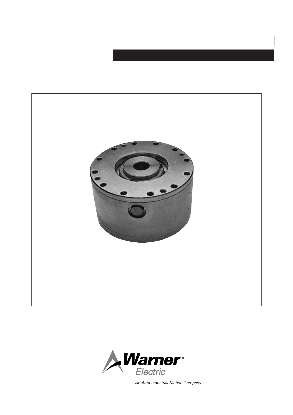
Centrifugal Brakes
FC-G-C410
Service Manual
Page 2
We, WARNER ELECTRIC EUROPE, 7, rue Champfleur, B.P. 20095, F-49182 St Barthélemy d’Anjou Cedex
declare that the torque limiters made in our factory from St Barthélemy d’Anjou,
and hereafter designated : FC-G-C410
are exclusively designed for incorporation into a machine and to be assembled with other equipments to create a machine. The operation of
the product is submitted to the conformity of the complete equipment, following the provisions of the machinery directive 98/37/EC Drawn up
in St Barthélemy d’Anjou, July 2002
E. PRAT, General Managing Director
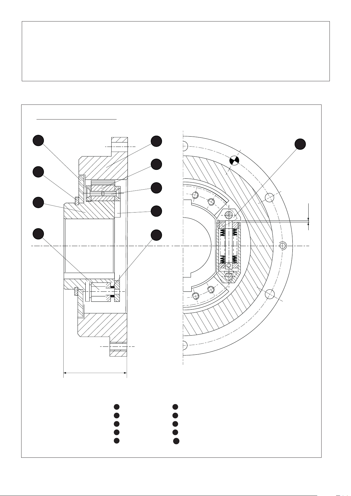
1 Technical specifications
8
10
3
2
9
7
1
6
4
5
“A”
L
1 Hub
2 Inertia Block
3 Spring
4 Axle
5 Spacer
2 Warner Electric Europe • +33 (0)2 41 21 24 24 P-2065-WE • 2/13
6 Flange
7 Fixing Screws
8 Closing Washer
9 Safety Ring
10 Drum
Fig. 1
Page 3
The FC-G - C140 centrifugal brake is a device
operating with delayed actuation that is to say, the
pressure between the friction surfaces is achieved by
the centrifugal force resul ting from the rotation of the
driving input. The engagement or disengagement is
therefore driven only by action upon the input side.
The device has no wear adjustment ; it operates only
in dry conditions ; the friction is of cast-iron-againstpacking type.
Example of description for a centrifugal device used
as brake with a zero torque at n = 1650 revolutions
per minute and a nominal torque of 20 m, daN for N
= 2700 revolu tions per minute.
Centrifugal brake, type FC 20 G - 1650/2700
4 ASSEMBLY
On our devices, hub and drum bores have
usually a H7 tolerance.
It can be mounted horizontally, vertically or in any
other position.
2 DESCRIPTION
The device consists of two main parts:
2.1 - The driving part includes:
- a hub fixed on the driving-shaft by means of a
key ;
- one, two or three sets of inertia-blocks
depending on the type) which are made integral
with the hub by means of the teeth ;.
- springs , which draw the inertia-blocks back
into the “disengaged or de-braked” position, are
articulated on the axles , are laterally kept
in position by the spacers and the flanges
and are fixed on the inertia-blocks by means
of the screws .
- a closing-washer , centered on the hub
and laterally kept in position by the safety-ring .
For fitting the device on the shaft, we advise to use
the js6 tolerance.
The width of the hub is key groove has the P9
tole rance.
The g6 tolerance is quite proper for the
centering designed to receive the drum .
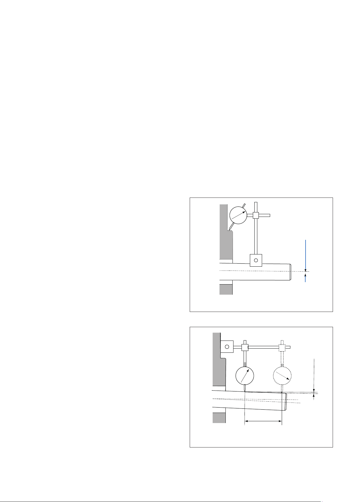
The shaft should not fall out of alignment with the
drum by a greater value than the one showed in
picture 3, while it should not be more eccentric than
in picture 2.
0,2 max.
2. 2 - The fixed part includes
- a drum centered on the driven member (clutch
use) or the frame o the machine (brake use) and
fixed by means of screws.
3 OPERATION
The device is rated to a zero torque for rotation
speeds of the driving-shaft below “n” revolutions per
minute, the iner tia-blocks being kept back by the
release springs .
For speeds greater than “n”, the inertia-blocks are
pushed into contact with the drum as a result of
the centrifugal force and the torque gradually grows
until it reaches its nominal value for “N” revolutions
per minute.
When the speed decreases, the torque gradually
decreases until it reaches its zero value for speeds
equal to or under “n” revolutions per minute.
NOTE - “n” and “N” values are engraved on every
device after the name of the type
Fig. 2
0,1 max.
100
Fig. 3
Warner Electric Europe • +33 (0)2 41 21 24 24 P-2065-WE • 2/13 3
Page 4

The device is supplied assembled.
For the mounting, prepare the unit as follows :
- remove the drum .
- take the safety-ring and the closing-ring
from the hub .
Mounting
6 ADJUSTMENT
The centrifugal device FC-G needs no further
adjustment since it is originally set for a given torque.
The wear of the packing depends on the work
absorbed by this device
For replacing of used inertia-blocks, remove the
block consisting of the hub , the inertia-blocks ,
the springs etc... from the machine.
After fitting the key into its housing :
- slide the driving member consisting of
the hub , the inertia-blocks , the springs
etc... on the shaft ;
- stop this block laterally by means of either a
nut with its lock washer, or a safety-ring or a ring
with a screw, which will have to be locked by using
a thermoplastic liquid like for example “LOCTITE
brake-normal thread”;
Warning
- For this setting process, never strike on the checks
and springs . Place a piece of soft alloy bet
ween the hub and the system chosen for
pushing the block on the shaft.
- Center the drum on the driven member or on
the frame of the machine and screw it into place.
Lock the screws energetically ;a thermoplastic
liquid like for example “LOCTITE brake-normal
thread” will provide for their stopping.
- Check in a few places, by using wedges, whether
the play between the inertia-blocks packing and
the internal diameter of the drum is roughly
regular.
- Fit the closing-washer and put the safety-ring
into its groove. To prevent the closing-washer
rubbing against the drum , keep the length
“L”.
- Counter-bore 2 holes opposite one another in
the driven member or in the frame of the machine
through the already existing ones in the
drum and slip elastic pins of, for example, the
“MECANINDUS” type into these holes. (except
special drum)
- Engage or brake a few times in getting the
machine to work.
6. 1 – Disassembly
- take away the safety-ring and the closing-
washer.
- remove the screws fixing the drum .
- dismount the drum by screwing two of the fixing
screws into the tapped holes specially designed
for this purpose. (except special drum)
- remove from the shaft, the block consisting
of the hub , the inertia-blocks the
springs etc...
After having removed the above sub-assembly
- Insert conical wedges into space “A”, namely
between the 2 moving parts of the release-spring
so that the inertia-blocks do not bear any
more on the periphery of the hub as a result of
the pressure from the springs . If the
device is equipped with traditional draw
springs, stretch these springs with pliers in
order to relieve the inertia-blocks from the
pressure exerted by the springs.
- Remove the screws on each face of the flanges
and withdraw the used inertia-blocks. Do not
reverse the assembling direction of the springs.
- Put the new inertia-blocks between the flanges
, install the screws while not for getting to
lock them by means of a thermoplastic liquid like,
for example, “LOCTITE brake-normal thread”.
- Drive away the conical wedges or let down
the draw-springs in order to bring the inertia blocks into contact with the hub .
- Reassemble the device on the machine. For this
process, see chapter 4 - ASSEMBLY.
5 NOTES
Keep the inertia-blocks packing off grease and
water, otherwise a reduction of the braking torque
could follow.
4 Warner Electric Europe • +33 (0)2 41 21 24 24 P-2065-WE • 2/13
Page 5

Theorical torque / speed
800
750
700
650
600
550
500
450
Nil torque (RPM) 1300
Nominal torque (RPM) 2500
400
(Nm)(Nm)
350
300
250
200
150
100
50
0
1300 1450 1600 1750 1900
80
40
20
2050 2200 2350 2500
(tr/min)
100
75
50
10
5
25
0
1300 1450 1600 1750 1900
(tr/min)
Warner Electric Europe • +33 (0)2 41 21 24 24 P-2065-WE • 2/13 5
2050 2200 2350 2500
Page 6

Theorical torque / speed
800
750
700
650
600
550
500
450
400
(Nm)
Nil torque (RPM) 1650
Nominal torque (RPM) 2700
350
300
250
200
150
100
50
0
1650 1800 1950 2100 2250
100
80
40
20
2400 2550 2700
(tr/min)
75
50
25
0
1650 1800 1950 2100 2250
6 Warner Electric Europe • +33 (0)2 41 21 24 24 P-2065-WE • 2/13
10
5
2400 2550 2700
(tr/min)
Page 7

Theorical torque / speed
800
750
700
650
600
550
500
450
Nil torque (RPM) 1850
Nominal torque (RPM) 2800
400
(Nm)
350
300
250
200
150
100
50
0
1850 2000 2150 2300 2450
80
40
20
2600 2750 2900
(tr/min)
100
75
10
50
5
(Nm)
25
0
1850 2000 2150 2300 2450
(tr/min)
Warner Electric Europe • +33 (0)2 41 21 24 24 P-2065-WE • 2/13 7
2600 2750 2900
Page 8

Warranty
Warner Electric LLC warrants that it will repair or replace (whichever it deems advisable) any product manufactured and
sold by it which proves to be defective in material or workmanship within a period of one (1) year from the date of original
purchase for consumer, commercial or industrial use.
This warranty extends only to the original purchaser and is not transferable or assignable without Warner Electric LLC’s
prior consent.
Warranty service can be obtained in the U.S.A. by returning any defective product, transportation charges prepaid, to
the appropriate Warner Electric LLC factory. Additional warranty information may be obtained by writing the Customer
Satisfaction Department, Warner Electric LLC, 449 Gardner Street, South Beloit, Illinois 61080, or by calling 815-389-
3771.
A purchase receipt or other proof of original purchase will be required before warranty service is rendered. If found
defective under the terms of this warranty, repair or replacement will be made, without charge, together with a refund for
transportation costs. If found not to be defective, you will be notified and, with your consent, the item will be repaired or
replaced and returned to you at your expense.
This warranty covers normal use and does not cover damage or defect which results from alteration, accident, neglect, or
improper installation, operation, or maintenance.
Some states do not allow limitation on how long an implied warranty lasts, so the above limitation may not apply to you.
Warner Electric LLC’s obligation under this warranty is limited to the repair or replacement of the defective product and
in no event shall Warner Electric LLC be liable for consequential, indirect, or incidental damages of any kind incurred by
reason of the manufacture, sale or use of any defective product. Warner Electric LLC neither assumes nor authorizes any
other person to give any other warranty or to assume any other obligation or liability on its behalf.
WITH RESPECT TO CONSUMER USE OF THE PRODUCT, ANY IMPLIED WARRANTIES WHICH THE CONSUMER MAY
HAVE ARE LIMITED IN DURATION TO ONE YEAR FROM THE DATE OF ORIGINAL CONSUMER PURCHASE. WITH
RESPECT TO COMMERCIAL AND INDUSTRIAL USES OF THE PRODUCT, THE FOREGOING WARRANTY IS IN LIEU
OF AND EXCLUDES ALL OTHER WARRANTIES, WHETHER EXPRESSED OR IMPLIED BY OPERATION OF LAW OR
OTHERWISE, INCLUDING, BUT NOT LIMITED TO, ANY IMPLIED WARRANTIES OF MERCHANTABILITY OR FITNESS.
Some states do not allow the exclusion or limitation of incidental or consequential damages, so the above limitation or
exclusion may not apply to you. This warranty gives you specific legal rights and you may also have other rights which
vary from state to state.
Changes in Dimensions and Specications
All dimensions and specifications shown in Warner Electric catalogs are subject to change without notice. Weights do not
include weight of boxing for shipment. Certified prints will be furnished without charge on request to Warner Electric.
Warner Electric Europe
7 rue Champfleur, B.P. 20095, St Barthelemy d’Anjou - France
+33 (0)2 41 21 24 24 • Fax: +33 (0)2 41 21 24 70
www.warnerelectric.com
Printed in USAP-2065-WE • 2/13
 Loading...